JP4977438B2 - Communication device and portable communication terminal using the same - Google Patents
Communication device and portable communication terminal using the sameDownload PDFInfo
- Publication number
- JP4977438B2 JP4977438B2JP2006289335AJP2006289335AJP4977438B2JP 4977438 B2JP4977438 B2JP 4977438B2JP 2006289335 AJP2006289335 AJP 2006289335AJP 2006289335 AJP2006289335 AJP 2006289335AJP 4977438 B2JP4977438 B2JP 4977438B2
- Authority
- JP
- Japan
- Prior art keywords
- communication
- shared antenna
- resonance frequency
- antenna
- function
- Prior art date
- Legal status (The legal status is an assumption and is not a legal conclusion. Google has not performed a legal analysis and makes no representation as to the accuracy of the status listed.)
- Active
Links
Images


Classifications
- H—ELECTRICITY
- H01—ELECTRIC ELEMENTS
- H01Q—ANTENNAS, i.e. RADIO AERIALS
- H01Q7/00—Loop antennas with a substantially uniform current distribution around the loop and having a directional radiation pattern in a plane perpendicular to the plane of the loop
- G—PHYSICS
- G06—COMPUTING OR CALCULATING; COUNTING
- G06K—GRAPHICAL DATA READING; PRESENTATION OF DATA; RECORD CARRIERS; HANDLING RECORD CARRIERS
- G06K19/00—Record carriers for use with machines and with at least a part designed to carry digital markings
- G06K19/06—Record carriers for use with machines and with at least a part designed to carry digital markings characterised by the kind of the digital marking, e.g. shape, nature, code
- G06K19/067—Record carriers with conductive marks, printed circuits or semiconductor circuit elements, e.g. credit or identity cards also with resonating or responding marks without active components
- G06K19/07—Record carriers with conductive marks, printed circuits or semiconductor circuit elements, e.g. credit or identity cards also with resonating or responding marks without active components with integrated circuit chips
- G06K19/077—Constructional details, e.g. mounting of circuits in the carrier
- G06K19/07749—Constructional details, e.g. mounting of circuits in the carrier the record carrier being capable of non-contact communication, e.g. constructional details of the antenna of a non-contact smart card
- G06K19/07766—Constructional details, e.g. mounting of circuits in the carrier the record carrier being capable of non-contact communication, e.g. constructional details of the antenna of a non-contact smart card comprising at least a second communication arrangement in addition to a first non-contact communication arrangement
- G06K19/07767—Constructional details, e.g. mounting of circuits in the carrier the record carrier being capable of non-contact communication, e.g. constructional details of the antenna of a non-contact smart card comprising at least a second communication arrangement in addition to a first non-contact communication arrangement the first and second communication means being two different antennas types, e.g. dipole and coil type, or two antennas of the same kind but operating at different frequencies
- G—PHYSICS
- G06—COMPUTING OR CALCULATING; COUNTING
- G06K—GRAPHICAL DATA READING; PRESENTATION OF DATA; RECORD CARRIERS; HANDLING RECORD CARRIERS
- G06K7/00—Methods or arrangements for sensing record carriers, e.g. for reading patterns
- G06K7/0008—General problems related to the reading of electronic memory record carriers, independent of its reading method, e.g. power transfer
- G—PHYSICS
- G06—COMPUTING OR CALCULATING; COUNTING
- G06K—GRAPHICAL DATA READING; PRESENTATION OF DATA; RECORD CARRIERS; HANDLING RECORD CARRIERS
- G06K7/00—Methods or arrangements for sensing record carriers, e.g. for reading patterns
- G06K7/10—Methods or arrangements for sensing record carriers, e.g. for reading patterns by electromagnetic radiation, e.g. optical sensing; by corpuscular radiation
- G06K7/10009—Methods or arrangements for sensing record carriers, e.g. for reading patterns by electromagnetic radiation, e.g. optical sensing; by corpuscular radiation sensing by radiation using wavelengths larger than 0.1 mm, e.g. radio-waves or microwaves
- G06K7/10237—Methods or arrangements for sensing record carriers, e.g. for reading patterns by electromagnetic radiation, e.g. optical sensing; by corpuscular radiation sensing by radiation using wavelengths larger than 0.1 mm, e.g. radio-waves or microwaves the reader and the record carrier being capable of selectively switching between reader and record carrier appearance, e.g. in near field communication [NFC] devices where the NFC device may function as an RFID reader or as an RFID tag
- H—ELECTRICITY
- H01—ELECTRIC ELEMENTS
- H01Q—ANTENNAS, i.e. RADIO AERIALS
- H01Q1/00—Details of, or arrangements associated with, antennas
- H01Q1/12—Supports; Mounting means
- H01Q1/22—Supports; Mounting means by structural association with other equipment or articles
- H01Q1/2208—Supports; Mounting means by structural association with other equipment or articles associated with components used in interrogation type services, i.e. in systems for information exchange between an interrogator/reader and a tag/transponder, e.g. in Radio Frequency Identification [RFID] systems
- H01Q1/2225—Supports; Mounting means by structural association with other equipment or articles associated with components used in interrogation type services, i.e. in systems for information exchange between an interrogator/reader and a tag/transponder, e.g. in Radio Frequency Identification [RFID] systems used in active tags, i.e. provided with its own power source or in passive tags, i.e. deriving power from RF signal
Landscapes
- Engineering & Computer Science (AREA)
- Physics & Mathematics (AREA)
- General Physics & Mathematics (AREA)
- Theoretical Computer Science (AREA)
- Health & Medical Sciences (AREA)
- Computer Vision & Pattern Recognition (AREA)
- Artificial Intelligence (AREA)
- Toxicology (AREA)
- Computer Hardware Design (AREA)
- Microelectronics & Electronic Packaging (AREA)
- Electromagnetism (AREA)
- General Health & Medical Sciences (AREA)
- Near-Field Transmission Systems (AREA)
Description
Translated fromJapanese本発明は通信装置及びそれを用いた携帯通信端末に関し、特に非接触型通信機能を有するRF−IDタグ(ICカード)機能とリーダ/ライタ機能との両機能を有する通信装置及びそれを用いた携帯通信端末に関するものである。 The present invention relates to a communication device and a portable communication terminal using the communication device, and more particularly to a communication device having both an RF-ID tag (IC card) function having a contactless communication function and a reader / writer function, and the same. The present invention relates to a mobile communication terminal.
ICカード機能とリーダ/ライタ機能とを有するRF−ID(Radio Frequency Identification)装置があり、図7にその概略機能ブロック図を示す。図7を参照すると、RF−ID装置100は、ICカード機能回路1と、リーダ/ライタ機能回路2と、これ等回路1,2を制御する制御回路3と、これら各回路1〜3間を接続する制御線4と、受信アンテナ5と、送信アンテナ6と、受信用共振周波数調整回路7と、送信用共振周波数調整回路8とを含んで構成されている。 There is an RF-ID (Radio Frequency Identification) device having an IC card function and a reader / writer function, and FIG. 7 shows a schematic functional block diagram thereof. Referring to FIG. 7, the RF-
受信アンテナ5は受信用共振周波数調整回路7と並列接続されており、これら受信アンテナ5と受信用共振周波数調整回路7とは、ICカード機能時において、通信距離特性が最良となるように調整されている。また、送信アンテナ6は送信用共振周波数調整回路8と直列接続されており、これら送信アンテナ6と送信用共振周波数調整回路8とは、リーダ/ライタ機能時において、通信距離特性が最良となるように調整されている。 The
ICカード(RF−IDタグ)機能時におけるデータ送受信について説明する。交通機関の改札機などに設置されている外部リーダ/ライタ装置(図示せず)との通信においては、受信アンテナ5を経由して外部リーダ/ライタ装置から所定変調方式で変調出力された受信データは、ICカード機能回路1へ入力されて復調され、制御線4を介して制御部3へ必要なデータが供給される。ICカード機能回路1から外部リーダ/ライタ装置への応答は、上記の変調方式とは異なる消費電力の小さい負荷変調にて行われる。 Data transmission / reception at the time of IC card (RF-ID tag) function will be described. In communication with an external reader / writer device (not shown) installed in a ticket gate of a transportation facility, received data modulated and output from the external reader / writer device by a predetermined modulation method via the
次に、リーダ/ライタ機能時におけるデータ送受信について説明する。図示せぬ外部の非接触型のICカードとの通信においては、リーダ/ライタ機能回路2から上記の所定変調方式による変調データが出力されて、送信アンテナ6を経由して、ICカードにデータ転送がなされる。外部の非接触型のICカードからの負荷変調による応答時には、受信アンテナ5を介してICカード機能回路1により受信がなされるようになっている。 Next, data transmission / reception at the time of the reader / writer function will be described. In communication with an external non-contact type IC card (not shown), modulated data by the above-described predetermined modulation method is output from the reader /
この様なRF−ID装置100においては、ICカード機能における通信特性向上のために、受信アンテナ5の面積を大きくし巻き数を多くする必要がある。一方、リーダ/ライタ機能における通信特性向上のためには、送信アンテナ6の面積を小さくし巻き数を少なくする必要がある。従ってこれら両アンテナは装置100内においてそれぞれ独立して個別に実装する必要がある。具体的には、RF−ID装置100の実装平面図である図8を参照すると、受信アンテナ5のループの内側に、送信アンテナ6をループ状に実装する形状となる。 In such an RF-
この様に、ICカード機能のアンテナとリーダ/ライタ機能のアンテナとは、互いに相反する特性であり、図8に示す如く、アンテナ実装面積が大となって、最近の小型化傾向にある携帯型の通信機器においては、極めて不利な実装方式とならざるを得ないものである。 Thus, the IC card function antenna and the reader / writer function antenna have mutually contradictory characteristics, and as shown in FIG. In such communication devices, this is an extremely disadvantageous mounting method.
ここで、特許文献1を参照すると、ICカード機能とリーダ/ライタ機能とを備えた通信装置において、両機能用のアンテナを共有する技術が開示されている。この技術では、両機能用のアンテナを共有する際に、それらの間で、送受信される電波の干渉をなくすために、一方の機能が実行されているときには、他方の機能の実行を禁止するというものである。
上記の特許文献1の技術では、ICカード機能とリーダ/ライタ機能とのアンテナを共有する構造は開示されてはいるものの、アンテナ共有のための具体的構成は何等開示されていない。上述したように、両機能のアンテナは、その特性が互いに相反するために、ただ単に共有化しただけでは、要求されるRF特性は得られず、従って、両アンテナの特性を損うことなくアンテナ共有のための具体的実現手段が望まれることになる。 In the technique of
本発明の目的は、特性が相反する受信用アンテナと送信用アンテナとを共有化するに際し、両アンテナの特性を損うことなく共有化可能な携帯通信装置を提供することである。 An object of the present invention is to provide a portable communication device that can share a receiving antenna and a transmitting antenna having opposite characteristics without damaging the characteristics of both antennas.
本発明による通信装置は、
外部の第一の非接触型通信装置と非接触型通信をなす第一の通信機能部と、前記第一の通信機能部と同一の通信機能を有し、前記第一の非接触型通信装置と同一の通信機能を有する外部の第二の非接触型通信装置と非接触型通信をなす第二の通信機能部と、を含む通信装置であって、
前記第一及び第二の通信機能部に共通の共有アンテナと、
前記第一及び第二の通信機能部のそれぞれに対する前記共有アンテナの共振周波数切替えのための共振周波数切替手段と、
前記共有アンテナに直列接続されて前記第二の通信機能部から前記共有アンテナを見たインピーダンスを調整するための送信用共振周波数調整手段と、
を含むことを特徴とする。A communication device according to the present invention comprises:
A first communication function unit that performs non-contact communication with an external first non-contact type communication device; and the first non-contact type communication device having the same communication function as the first communication function unit A second communication function unit that performs non-contact communication with an external second non-contact communication device having the same communication function as
A shared antenna common to the first and second communication function units;
Resonance frequency switching means for switching the resonance frequency of the shared antenna for each of the first and second communication function units;
Resonance frequency adjusting means for transmission for adjusting the impedance when the shared antenna is viewed from the second communication function unit connected in series to the shared antenna;
It is characterized by including.
そして、前記共振周波数切替手段は、前記第一及び第二の通信機能部の各動作時に共振周波数の自動切替えをなすことを特徴とする。また、前記第一の通信機能部はRF−IDタグであり、前記第二の通信機能部は前記RF−IDタグとの通信をなすリーダ/ライタ装置であることを特徴とする。 The resonance frequency switching means automatically switches the resonance frequency during each operation of the first and second communication function units. The first communication function unit is an RF-ID tag, and the second communication function unit is a reader / writer device that communicates with the RF-ID tag.
また、前記共有アンテナはループ状であることを特徴とし、前記共有アンテナのループ内に回路部品を実装したことを特徴とする。更に、前記共有アンテナはプリント基板上に磁性材を介して実装されていることを特徴とする。 The shared antenna may have a loop shape, and circuit components may be mounted in the loop of the shared antenna. Furthermore, the shared antenna is mounted on a printed board via a magnetic material.
そして、本発明による携帯通信端末は、上記構成の通信装置を含むことを特徴としている。 And the portable communication terminal by this invention is characterized by including the communication apparatus of the said structure.
本発明による第1の効果は、送受信用共振周波数切替機能を設けることにより送受信アンテナを共有するようにしたので、両アンテナの各々の特性を損うことなく、共有化が可能となって、実装面積の節約が可能になることである。 The first effect of the present invention is that the transmission / reception antenna is shared by providing the transmission / reception resonance frequency switching function. Therefore, the antenna can be shared without deteriorating the characteristics of both antennas. It is possible to save area.
本発明による第2の効果は、両アンテナを共有できることにより、ループ状アンテナのループ内の開口部分に、他の回路部品を実装可能となって、更なる実装面積の節約が実現できることである。 The second effect of the present invention is that, since both antennas can be shared, other circuit components can be mounted in the opening in the loop of the loop-shaped antenna, and further mounting area saving can be realized.
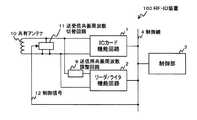
以下に図面を参照しつつ本発明の実施の形態について説明する。図1は本実施の形態の概略機能ブロック図であり、図7と同等部分は同一符号により示している。本実施の形態のRF−ID装置100は、ICカード機能回路1と、リーダ/ライタ機能回路2と、これら各回路1,2を制御する制御回路3と、これ等各回路1〜3間を接続する制御線4と、送信用共振周波数調整回路8と、共有アンテナ10と、送受信共振周波数切替回路11とを含んで構成されている。 Embodiments of the present invention will be described below with reference to the drawings. FIG. 1 is a schematic functional block diagram of the present embodiment, and the same parts as those in FIG. 7 are denoted by the same reference numerals. The RF-
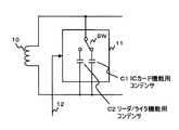
送信用共振周波数調整回路8は、リーダ/ライタ機能回路2からみたインピーダンスを下げる目的で、共有アンテナ10と直列接続されている。送受信共振周波数切替回路11は共有アンテナ10と並列接続されており、制御部3からの制御信号12により、送受信共振周波数の切替えが行われるようになっている。この送受信共振周波数切替回路11の具体例が図2に示されている。 The transmission resonance frequency adjusting circuit 8 is connected in series with the shared
図2において、スイッチSWは、制御部3からの制御信号12により切替制御されて、コンデンサC1とC2とのいずれかを、共有アンテナ10に並列接続するよう選択するものである。コンデンサC1はICカード機能用のコンデンサであり、コンデンサC2はリーダ/ライタ機能用のコンデンサである。 In FIG. 2, the switch SW is switch-controlled by the
コンデンサC1と共有アンテナ10との並列共振周波数は、RF−ID装置100と外部リーダ/ライタ装置との通信特性に依存性があるので、この通信特性が良好となるように、その値ficが定められる。このficからICカード機能用コンデンサC1が決定されることになる。一方、リーダ/ライタ機能用のコンデンサC2は、比較的容量が小さい方がRF−ID装置100と外部のICカード(図示せず)との間の通信距離特性が得られるので、このコンデンサC2の容量値は、通信距離が良好となる点で決定されることになる。 Since the parallel resonance frequency of the capacitor C1 and the shared
ICカード(RF−IDタグ)機能時におけるデータの送受信について説明する。このとき、共有アンテナ10は送受信共振周波数切替回路11のコンデンサC1と自動的に並列接続される。例えば、交通機関の改札機などで使用される外部のリーダ/ライタ装置との通信時には、共有アンテナ10を経由して所定変調方式で変調されたデータが受信され、ICカード機能回路1にて復調されて制御線4を介して制御部3へ必要なデータが送信される。ICカード機能回路1からの外部リーダ/ライタ装置への応答は、上記変調方式とは異なる負荷変調により行われることになる。 Data transmission / reception when the IC card (RF-ID tag) function is performed will be described. At this time, the shared
次に、リーダ/ライタ機能時におけるデータ送受信について説明する。このとき、共有アンテナ10は送受信共振周波数切替回路11のコンデンサC2と自動的に並列接続される。一般の非接触型のICカード(RF−IDタグ)との通信においては、リーダ/ライタ機能回路2から上記の所定変調方式による変調データが出力され、共有アンテナ10を経由してICカードにデータが転送される。ICカードからの負荷変調による応答時には、共有アンテナ10を介してICカード機能回路1にて受信されることになる。 Next, data transmission / reception at the time of the reader / writer function will be described. At this time, the shared
図3及び図4は共有アンテナ10の実装方法について説明する図であり、図3はその斜視図、図4はその断面図である。これら図に示す如く、共有アンテナ10は、FPC(Flexible Printed Circuit)、プリント基板、銅線などで作成することができる。図3に示すように、共有アンテナ10はループ状に形成されている。 3 and 4 are views for explaining a mounting method of the shared
RF−ID装置100は、携帯通信端末などの実装条件が厳しい通信装置に実装される場合には、共有アンテナ10と回路が搭載されたプリント基板20との距離が極めて小さいために、共有アンテナ10のインダクタンスは、プリント基板20のグランド配線の影響を受けるので、磁性シート21を共有アンテナ10の下部に設ける。なお、本例では、プリント基板20上に共有アンテナ10を設けているが、電池パックなどの金属の上に設けても良いものである。 When the RF-
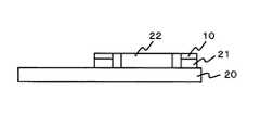
図5及び図6は共有アンテナ10の他の実装方法を示す図であり、図5はその斜視図、図6はその断面図である。両図において、図3及び図4と同等部分は同一符号により示されている。本例では、共有アンテナ10と磁性シート21の中央部分を開口し、この開口部分に回路部品22を実装したものである。こうすることにより、共有アンテナ10のループの内側部分を、有効に利用できるので、小型の通信装置には極めて好適である。 5 and 6 are diagrams showing another mounting method of the shared
この様に、共有アンテナ10と磁性シート21とを開口すると、図3及び図4の開口しない場合に比べて、リーダ/ライタ機能における通信距離が劣化する。この劣化は、リーダ/ライタ機能用コンデンサC2の容量を、通信距離が良好となるように調整することによって補償できるものである。 As described above, when the shared
本発明は、外部のリーダ/ライタ装置と非接触型で情報の授受を行うICカード(RF−IDタグ)機能と、外部のICカードと非接触型で情報の授受を行うリーダ/ライタ機能とを内蔵した通信装置に適用される他、この通信装置を備えた携帯通信端末(携帯電話機、携帯型デジタルカメラ、携帯型デジタル音響機器、PDA(Personal Digital Assistant)など)に適用可能である。 The present invention relates to an IC card (RF-ID tag) function for exchanging information with an external reader / writer device in a contactless manner, and a reader / writer function for exchanging information with an external IC card in a contactless manner. In addition to being applied to a communication device having a built-in, it can be applied to a mobile communication terminal (such as a mobile phone, a portable digital camera, a portable digital audio device, a PDA (Personal Digital Assistant)) provided with the communication device.
1 ICカード(RF−IDタグ)機能回路
2 リーダ/ライタ機能回路
3 制御部
4 制御線
8 送信用共振周波数調整回路
10 共有(共通)アンテナ
11 送受信共振周波数切替回路
12 制御信号
20 プリント基板
21 磁性シート
100 RF−ID装置
SW スイッチ
C1,C2 コンデンサ1 IC card (RF-ID tag) functional circuit
2 Reader / writer function circuit
3 Control unit
4 Control lines
8 Transmission Resonance
Claims (7)
Translated fromJapanese前記第一及び第二の通信機能部に共通の共有アンテナと、
前記第一及び第二の通信機能部のそれぞれに対する前記共有アンテナの共振周波数切替えのための共振周波数切替手段と、
前記共有アンテナに直列接続されて前記第二の通信機能部から前記共有アンテナを見たインピーダンスを調整するための送信用共振周波数調整手段と、
を含むことを特徴とする通信装置。A first communication function unit that performs non-contact communication with an external first non-contact type communication device; and the first non-contact type communication device having the same communication function as the first communication function unit A second communication function unit that performs non-contact communication with an external second non-contact communication device having the same communication function as
A shared antenna common to the first and second communication function units;
Resonance frequency switching means for switching the resonance frequency of the shared antenna for each of the first and second communication function units;
Resonance frequency adjusting means for transmission for adjusting the impedance when the shared antenna is viewed from the second communication function unit connected in series to the shared antenna;
A communication device comprising:
Priority Applications (7)
| Application Number | Priority Date | Filing Date | Title |
|---|---|---|---|
| JP2006289335AJP4977438B2 (en) | 2006-10-25 | 2006-10-25 | Communication device and portable communication terminal using the same |
| US12/447,090US8125337B2 (en) | 2006-10-25 | 2007-10-23 | Communication apparatus and portable communication terminal using the same |
| PCT/JP2007/070671WO2008050777A1 (en) | 2006-10-25 | 2007-10-23 | Communication device and portable communication terminal using the same |
| EP20140171287EP2793174A1 (en) | 2006-10-25 | 2007-10-23 | Communication device and portable communication terminal using the same |
| EP07830405AEP2088538A4 (en) | 2006-10-25 | 2007-10-23 | Communication device and portable communication terminal using the same |
| CN200780040112.8ACN101529449B (en) | 2006-10-25 | 2007-10-23 | Communicator and the mobile terminals of this communicator of use |
| US13/347,340US8373560B2 (en) | 2006-10-25 | 2012-01-10 | Communication apparatus and portable communication terminal using the same |
Applications Claiming Priority (1)
| Application Number | Priority Date | Filing Date | Title |
|---|---|---|---|
| JP2006289335AJP4977438B2 (en) | 2006-10-25 | 2006-10-25 | Communication device and portable communication terminal using the same |
Publications (2)
| Publication Number | Publication Date |
|---|---|
| JP2008108016A JP2008108016A (en) | 2008-05-08 |
| JP4977438B2true JP4977438B2 (en) | 2012-07-18 |
Family
ID=39324574
Family Applications (1)
| Application Number | Title | Priority Date | Filing Date |
|---|---|---|---|
| JP2006289335AActiveJP4977438B2 (en) | 2006-10-25 | 2006-10-25 | Communication device and portable communication terminal using the same |
Country Status (5)
| Country | Link |
|---|---|
| US (2) | US8125337B2 (en) |
| EP (2) | EP2793174A1 (en) |
| JP (1) | JP4977438B2 (en) |
| CN (1) | CN101529449B (en) |
| WO (1) | WO2008050777A1 (en) |
Families Citing this family (14)
| Publication number | Priority date | Publication date | Assignee | Title |
|---|---|---|---|---|
| JP2009135710A (en)* | 2007-11-29 | 2009-06-18 | Toshiba Corp | Wireless device and antenna device |
| JP2009176027A (en)* | 2008-01-24 | 2009-08-06 | Toshiba Corp | Wireless communication apparatus and wireless communication system |
| JP2010098600A (en)* | 2008-10-17 | 2010-04-30 | Panasonic Corp | Non-contact communication device |
| US8682261B2 (en)* | 2009-02-13 | 2014-03-25 | Qualcomm Incorporated | Antenna sharing for wirelessly powered devices |
| JP5640655B2 (en)* | 2010-10-29 | 2014-12-17 | ソニー株式会社 | Portable communication device, reader / writer device, and resonance frequency adjusting method |
| JP5626043B2 (en)* | 2011-03-10 | 2014-11-19 | 株式会社村田製作所 | RFID reader / writer with RFID tag function and RFID reader / writer module with RFID tag function |
| US8917160B2 (en)* | 2011-03-21 | 2014-12-23 | Sony Corporation | RFID module |
| CN102739291B (en)* | 2011-04-02 | 2014-08-13 | 国民技术股份有限公司 | Near field communication module, system and method thereof |
| FR2988195B1 (en) | 2012-03-14 | 2015-04-10 | Continental Automotive France | NEAR-FIELD DETECTION AND COMMUNICATION DEVICE |
| KR102022867B1 (en)* | 2012-08-07 | 2019-09-20 | 삼성전자 주식회사 | Near field communication circuit and operating method of the same |
| SK288677B6 (en)* | 2015-06-02 | 2019-06-04 | Logomotion, S.R.O. | Method of processing of signal transmitted from the analog NFC driver and system for realization of said method |
| CN106056019B (en)* | 2016-05-24 | 2019-06-14 | 北京工业大学 | A high-temperature and low-frequency antenna and its drive amplifier circuit system for discrete devices |
| CN107066907A (en)* | 2016-12-19 | 2017-08-18 | 徐学军 | Merchandise control and the method purchased again |
| CN112084797A (en)* | 2020-08-21 | 2020-12-15 | 中国人民解放军海军工程大学 | A handheld terminal device for identifying special materials |
Family Cites Families (17)
| Publication number | Priority date | Publication date | Assignee | Title |
|---|---|---|---|---|
| JPH04278691A (en)* | 1991-03-06 | 1992-10-05 | Omron Corp | Non-contact type pass gate system |
| US5942977A (en)* | 1997-08-13 | 1999-08-24 | Ludwig Kipp | Radio transponder |
| US6351215B2 (en)* | 1998-06-02 | 2002-02-26 | Rf Code, Inc. | Monitoring antenna system |
| WO2001067551A1 (en) | 2000-03-06 | 2001-09-13 | Mitsubishi Denki Kabushiki Kaisha | Transmitting and receiving antenna |
| US6480110B2 (en)* | 2000-12-01 | 2002-11-12 | Microchip Technology Incorporated | Inductively tunable antenna for a radio frequency identification tag |
| JP4232434B2 (en)* | 2002-10-28 | 2009-03-04 | ソニー株式会社 | Semiconductor integrated circuit device, wireless communication terminal |
| WO2004073108A1 (en)* | 2003-02-14 | 2004-08-26 | Kabushiki Kaisha Toshiba | Electronic device |
| CA2533029C (en)* | 2003-07-22 | 2014-06-03 | Nokia Corporation | Reader device for radio frequency identification transponder with transponder functionality |
| JP2005122595A (en)* | 2003-10-20 | 2005-05-12 | Matsushita Electric Ind Co Ltd | Proximity contactless communication equipment |
| JP4042702B2 (en)* | 2004-01-30 | 2008-02-06 | ソニー株式会社 | Portable information processing terminal device |
| JP2006025155A (en)* | 2004-07-07 | 2006-01-26 | Sony Corp | Communication device and semiconductor integrated circuit |
| JP2006067448A (en) | 2004-08-30 | 2006-03-09 | Ricoh Co Ltd | COMMUNICATION DEVICE AND PORTABLE ELECTRONIC DEVICE HAVING THE COMMUNICATION DEVICE |
| JP4618672B2 (en)* | 2004-09-02 | 2011-01-26 | フェリカネットワークス株式会社 | Semiconductor integrated circuit and wireless communication device |
| JP4496105B2 (en)* | 2005-02-28 | 2010-07-07 | 株式会社東芝 | Wireless communication device |
| KR100713752B1 (en)* | 2005-02-28 | 2007-05-07 | 가부시끼가이샤 도시바 | Wireless communication device, wireless communication method, and contactless IC card reader / writer |
| JP4812322B2 (en)* | 2005-04-08 | 2011-11-09 | パナソニック株式会社 | Mobile communication device |
| GB0507285D0 (en)* | 2005-04-11 | 2005-05-18 | Innovision Res & Tech Plc | Nfc enabled high-speed data |
- 2006
- 2006-10-25JPJP2006289335Apatent/JP4977438B2/enactiveActive
- 2007
- 2007-10-23EPEP20140171287patent/EP2793174A1/ennot_activeCeased
- 2007-10-23WOPCT/JP2007/070671patent/WO2008050777A1/enactiveApplication Filing
- 2007-10-23USUS12/447,090patent/US8125337B2/ennot_activeExpired - Fee Related
- 2007-10-23CNCN200780040112.8Apatent/CN101529449B/ennot_activeExpired - Fee Related
- 2007-10-23EPEP07830405Apatent/EP2088538A4/ennot_activeWithdrawn
- 2012
- 2012-01-10USUS13/347,340patent/US8373560B2/ennot_activeExpired - Fee Related
Also Published As
| Publication number | Publication date |
|---|---|
| US8125337B2 (en) | 2012-02-28 |
| EP2088538A4 (en) | 2011-11-09 |
| US20120105209A1 (en) | 2012-05-03 |
| WO2008050777A1 (en) | 2008-05-02 |
| JP2008108016A (en) | 2008-05-08 |
| CN101529449B (en) | 2016-08-17 |
| US20100001839A1 (en) | 2010-01-07 |
| US8373560B2 (en) | 2013-02-12 |
| EP2793174A1 (en) | 2014-10-22 |
| EP2088538A1 (en) | 2009-08-12 |
| CN101529449A (en) | 2009-09-09 |
Similar Documents
| Publication | Publication Date | Title |
|---|---|---|
| JP4977438B2 (en) | Communication device and portable communication terminal using the same | |
| EP1641140B1 (en) | Data communication device | |
| US8041295B2 (en) | Mobile communication device | |
| JP4393228B2 (en) | Small antenna and wireless tag provided with the same | |
| KR101232557B1 (en) | Mobile radio device | |
| KR20080007181A (en) | Contactless communication circuits and portable terminals | |
| US20070030207A1 (en) | Compact loop antenna for inductive read/write apparatus | |
| CN100568754C (en) | Communication device, noncontact IC card mounted with communication device, and information device | |
| WO2011001564A1 (en) | Antenna device and portable wireless apparatus provided with same | |
| JP2001344574A (en) | Antenna device for interrogator | |
| US8792837B2 (en) | Transmission/reception antenna and transmission/reception device using same | |
| JP2006262055A (en) | Antenna module and portable information terminal provided with the same | |
| JP2007088661A (en) | Information processing apparatus and loop antenna | |
| US20090224893A1 (en) | Communication device, non-contact type ic card mounting same, and information apparatus | |
| JP4769972B2 (en) | Wireless communication apparatus and wireless communication method | |
| JP4019850B2 (en) | Non-contact IC card reader / writer communication range adjustment method | |
| JP2008263295A (en) | Wireless communication terminal device and RFID module | |
| US8779982B2 (en) | System for reducing antenna gain deterioration | |
| CN112688063A (en) | Communication apparatus and communication method | |
| JP2004048297A (en) | Noncontact data transfer apparatus | |
| WO2013114491A1 (en) | Antenna device and portable wireless device | |
| JP2011165151A (en) | Radio communication device and noncontact communication antenna used for the same | |
| JP2011053896A (en) | Ic tag reading and writing device, electronic device, and ic tag reading and writing method | |
| JP5289908B2 (en) | Communication equipment | |
| JP2014135084A (en) | Radio communication device, and non-contact communication antenna used for the radio communication device |
Legal Events
| Date | Code | Title | Description |
|---|---|---|---|
| A621 | Written request for application examination | Free format text:JAPANESE INTERMEDIATE CODE: A621 Effective date:20090924 | |
| A131 | Notification of reasons for refusal | Free format text:JAPANESE INTERMEDIATE CODE: A131 Effective date:20111220 | |
| A521 | Request for written amendment filed | Free format text:JAPANESE INTERMEDIATE CODE: A523 Effective date:20120220 | |
| TRDD | Decision of grant or rejection written | ||
| A01 | Written decision to grant a patent or to grant a registration (utility model) | Free format text:JAPANESE INTERMEDIATE CODE: A01 Effective date:20120403 | |
| A01 | Written decision to grant a patent or to grant a registration (utility model) | Free format text:JAPANESE INTERMEDIATE CODE: A01 | |
| A61 | First payment of annual fees (during grant procedure) | Free format text:JAPANESE INTERMEDIATE CODE: A61 Effective date:20120416 | |
| R150 | Certificate of patent or registration of utility model | Ref document number:4977438 Country of ref document:JP Free format text:JAPANESE INTERMEDIATE CODE: R150 Free format text:JAPANESE INTERMEDIATE CODE: R150 | |
| FPAY | Renewal fee payment (event date is renewal date of database) | Free format text:PAYMENT UNTIL: 20150420 Year of fee payment:3 | |
| S111 | Request for change of ownership or part of ownership | Free format text:JAPANESE INTERMEDIATE CODE: R313115 | |
| R350 | Written notification of registration of transfer | Free format text:JAPANESE INTERMEDIATE CODE: R350 | |
| S111 | Request for change of ownership or part of ownership | Free format text:JAPANESE INTERMEDIATE CODE: R313117 | |
| R350 | Written notification of registration of transfer | Free format text:JAPANESE INTERMEDIATE CODE: R350 |