JP4974704B2 - Imaging device - Google Patents
Imaging deviceDownload PDFInfo
- Publication number
- JP4974704B2 JP4974704B2JP2007042065AJP2007042065AJP4974704B2JP 4974704 B2JP4974704 B2JP 4974704B2JP 2007042065 AJP2007042065 AJP 2007042065AJP 2007042065 AJP2007042065 AJP 2007042065AJP 4974704 B2JP4974704 B2JP 4974704B2
- Authority
- JP
- Japan
- Prior art keywords
- subject
- unit
- image
- camera shake
- face
- Prior art date
- Legal status (The legal status is an assumption and is not a legal conclusion. Google has not performed a legal analysis and makes no representation as to the accuracy of the status listed.)
- Expired - Fee Related
Links
Images


Classifications
- H—ELECTRICITY
- H04—ELECTRIC COMMUNICATION TECHNIQUE
- H04N—PICTORIAL COMMUNICATION, e.g. TELEVISION
- H04N23/00—Cameras or camera modules comprising electronic image sensors; Control thereof
- H04N23/60—Control of cameras or camera modules
- H04N23/61—Control of cameras or camera modules based on recognised objects
- H04N23/611—Control of cameras or camera modules based on recognised objects where the recognised objects include parts of the human body
- H—ELECTRICITY
- H04—ELECTRIC COMMUNICATION TECHNIQUE
- H04N—PICTORIAL COMMUNICATION, e.g. TELEVISION
- H04N23/00—Cameras or camera modules comprising electronic image sensors; Control thereof
- H04N23/60—Control of cameras or camera modules
- H04N23/68—Control of cameras or camera modules for stable pick-up of the scene, e.g. compensating for camera body vibrations
- H04N23/681—Motion detection
- H04N23/6811—Motion detection based on the image signal
- H—ELECTRICITY
- H04—ELECTRIC COMMUNICATION TECHNIQUE
- H04N—PICTORIAL COMMUNICATION, e.g. TELEVISION
- H04N23/00—Cameras or camera modules comprising electronic image sensors; Control thereof
- H04N23/60—Control of cameras or camera modules
- H04N23/68—Control of cameras or camera modules for stable pick-up of the scene, e.g. compensating for camera body vibrations
- H04N23/682—Vibration or motion blur correction
- H04N23/684—Vibration or motion blur correction performed by controlling the image sensor readout, e.g. by controlling the integration time
- H—ELECTRICITY
- H04—ELECTRIC COMMUNICATION TECHNIQUE
- H04N—PICTORIAL COMMUNICATION, e.g. TELEVISION
- H04N23/00—Cameras or camera modules comprising electronic image sensors; Control thereof
- H04N23/60—Control of cameras or camera modules
- H04N23/68—Control of cameras or camera modules for stable pick-up of the scene, e.g. compensating for camera body vibrations
- H04N23/682—Vibration or motion blur correction
- H04N23/685—Vibration or motion blur correction performed by mechanical compensation
- H04N23/687—Vibration or motion blur correction performed by mechanical compensation by shifting the lens or sensor position
- H—ELECTRICITY
- H04—ELECTRIC COMMUNICATION TECHNIQUE
- H04N—PICTORIAL COMMUNICATION, e.g. TELEVISION
- H04N23/00—Cameras or camera modules comprising electronic image sensors; Control thereof
- H04N23/70—Circuitry for compensating brightness variation in the scene
- H04N23/73—Circuitry for compensating brightness variation in the scene by influencing the exposure time
- H—ELECTRICITY
- H04—ELECTRIC COMMUNICATION TECHNIQUE
- H04N—PICTORIAL COMMUNICATION, e.g. TELEVISION
- H04N23/00—Cameras or camera modules comprising electronic image sensors; Control thereof
- H04N23/70—Circuitry for compensating brightness variation in the scene
- H04N23/76—Circuitry for compensating brightness variation in the scene by influencing the image signals
Landscapes
- Engineering & Computer Science (AREA)
- Multimedia (AREA)
- Signal Processing (AREA)
- Studio Devices (AREA)
- Exposure Control For Cameras (AREA)
- Adjustment Of Camera Lenses (AREA)
Description
Translated fromJapanese本発明は、撮像装置及びレンズ鏡筒に関し、より詳細には、カメラブレ補正機能と撮影感度変更機能とを備える撮像装置及びレンズ鏡筒に関する。 The present invention relates to an imaging device and a lens barrel, and more particularly to an imaging device and a lens barrel that have a camera shake correction function and a photographing sensitivity change function.
被写体の光学的な像を電気的な画像信号に変換して出力可能なデジタルスチルカメラやデジタルビデオカメラ等の撮像装置(以下、単にデジタルカメラという)が急速に普及している。特に近年では、デジタルカメラの小型・軽量化及び光学ズームの高倍率化が進み、撮影者等に対する使い勝手は格段に向上してきている。 Imaging devices (hereinafter simply referred to as digital cameras) such as digital still cameras and digital video cameras capable of converting an optical image of a subject into an electrical image signal and outputting the signals are rapidly spreading. In particular, in recent years, digital cameras have become smaller and lighter and optical zooms have increased in magnification, and usability for photographers and the like has been greatly improved.
しかし、デジタルカメラの小型・軽量化及び光学ズームの高倍率化に伴い、撮影した画像にブレが生じ、画質が劣化する場合がある。 However, along with the reduction in size and weight of digital cameras and the increase in optical zoom magnification, there are cases where the captured image becomes blurred and the image quality deteriorates.
特許文献1には、撮影時に像ブレ等が生じても画像への影響を軽減する振れ補正光学系を備えたデジタルカメラが開示されている。特許文献1に記載のデジタルカメラは、撮影時の像ブレに応じて補正レンズを光軸と垂直な上下左右方向に移動させ、画像の乱れを補正する。これにより、小型・軽量化したデジタルカメラであっても像ブレを軽減した画像を撮影することができる。また、特許文献1に記載のデジタルカメラは、像ブレを防ぐためにストロボを発光させて撮影する必要がないので、自然の色に近い条件下で雰囲気のある写真を撮影することができるとしている。
一方、撮影画像の画質を劣化させる原因としては、手ブレ等のようにカメラ本体に加わる振動に起因するカメラブレ以外にも、撮影対象となる被写体が動くことによって生じる被写体ブレがある。このような被写体ブレは、露光時間を短くして高速のシャッタースピードで撮影することにより防ぐことができる。シャッタースピードは、例えば撮影感度を高くしたり、ストロボ発光を行うことにより速くすることができる。以下、撮像面における被写体の光学像のブレに関し、カメラ本体に加わる振動に起因するものをカメラブレといい、被写体の動きに起因するものを被写体ブレといい、カメラブレと被写体ブレを総称して、撮像面に対する像ブレという。 On the other hand, the cause of deterioration of the image quality of a captured image includes subject blur caused by movement of a subject to be photographed, in addition to camera shake caused by vibration applied to the camera body such as camera shake. Such subject blur can be prevented by shortening the exposure time and shooting at a high shutter speed. The shutter speed can be increased by, for example, increasing the shooting sensitivity or performing strobe light emission. Hereinafter, regarding the blurring of the optical image of the subject on the imaging surface, the camera shake is caused by vibration applied to the camera body, the camera shake is caused by the movement of the subject, and the camera shake and the subject blur are collectively referred to as imaging. Image blurring on the surface.
特許文献2には、被写体の動きを推測する動き推測手段を備え、被写体が動く可能性が高い場合、シャッタースピードなどの撮影条件を変更する撮影装置及び方法が開示されている。
特許文献3には、画像データの中から人物の顔、さらには目、鼻、口を検出し、検出された人物の顔の一部を測距エリアとして、自動合焦制御を行う技術が開示されている。
一般に、撮影感度を高くすると撮像センサからの出力信号は増幅されるので、撮像センサから発生するノイズも増幅されることになる。そのため、高感度で撮影した画像にはノイズが多く含まれる。このように、必要以上に撮影感度を高くすることは画質劣化の原因ともなる。したがって、周囲の明るさが不十分なために振れ補正光学系により補正を行ってもなおカメラブレが発生する場合や、動きの速い被写体を撮影する場合等に撮影感度を高くすることが望ましい。 In general, when the shooting sensitivity is increased, the output signal from the image sensor is amplified, so that noise generated from the image sensor is also amplified. For this reason, an image photographed with high sensitivity contains a lot of noise. As described above, increasing the photographing sensitivity more than necessary also causes deterioration in image quality. Therefore, it is desirable to increase the shooting sensitivity when camera shake still occurs even when correction is performed by the shake correction optical system because the surrounding brightness is insufficient, or when a fast-moving subject is shot.
しかしながら、このような従来の撮像装置にあっては、撮影者等は、被写体がどの程度の速さで動けば被写体ブレが生じるのかを判断することは困難である。そのため、被写体ブレのない撮影が可能であるにもかかわらず、被写体の動きを観察した撮影者等は誤って被写体ブレが発生すると認識する場合がある。その結果、撮影者等は高感度の撮影感度に変更し、不必要にノイズを多く含む画像が撮影されるという問題があった。また、動きの速い被写体を撮影するためには、撮影直前に撮影者等は撮影感度を変更しなければならず、折角のシャッターチャンスを逃してしまうという問題があった。 However, in such a conventional imaging apparatus, it is difficult for a photographer or the like to determine how fast the subject moves to cause subject blurring. For this reason, a photographer who observes the movement of the subject may recognize that the subject blur occurs erroneously even though the subject blurring is possible. As a result, there has been a problem that the photographer changes to a high sensitivity and an image containing an unnecessarily large amount of noise is captured. In addition, in order to photograph a fast-moving subject, a photographer or the like has to change the photographing sensitivity immediately before the photographing, and there is a problem that a photo opportunity is missed.
すなわち、一般の撮影者にとっては、被写体の動き速度がどの程度であれば、被写体ブレが生じ、あるいは生じないという判断ができない。つまり、被写体速度が速い場合にカメラブレ補正機能を使用すれば、被写体ブレの生じた画像を撮影することになり、被写体速度が遅い場合にISO感度をアップさせると、ノイズが多い画像を撮影することになり、良好な映像を得ることができない。 That is, it is impossible for a general photographer to determine whether or not the subject blur occurs or does not occur at any speed. In other words, if the camera shake correction function is used when the subject speed is high, a subject-blurred image is taken, and if the ISO sensitivity is increased when the subject speed is slow, a noisy image is taken. Therefore, a good image cannot be obtained.
また、特許文献1に記載された振れ補正光学系を備えたデジタルカメラは、カメラブレによる画質劣化を軽減することができるものの、被写体ブレによる画質劣化を軽減することについては提案されていない。 The digital camera provided with the shake correction optical system described in
さらに、特許文献2に記載されたデジタルカメラは、被写体の動きを予測するだけであり被写体がどの程度の速さで動けば被写体ブレが生じるのかを判断するものではないため、被写体速度に合わせた最適なシャッタースピードにて撮影できるとは限らない。 Furthermore, since the digital camera described in
本発明は、かかる点に鑑みてなされたものであり、むやみに撮影感度を上げることを防止してカメラブレや被写体ブレによる画質劣化を軽減し、良好な画質の画像を容易に撮影することのできる撮像装置を提供することを目的とする。 The present invention has been made in view of the above points, and can prevent an excessive increase in shooting sensitivity, reduce image quality deterioration due to camera shake and subject blur, and easily shoot images with good image quality. An object is to provide an imaging device.
本発明の撮像装置は、被写体の光学像を形成する撮像光学系と、前記形成された光学像を受光して電気的な画像信号に変換して出力する撮像センサと、前記画像信号に基づいて被写体の顔を検出する顔検出部と、撮影前の所定時間における前記被写体の顔の光学像の動きを測定し、被写体速度を算出する被写体速度判定部と、算出した前記被写体速度が所定値以上の場合には、高い前記画像信号の増幅率、及び短い露出時間にて撮影を行う制御部と、を備える構成を採る。 An imaging apparatus according to the present invention is based on an imaging optical system that forms an optical image of a subject, an imaging sensor that receives the formed optical image, converts it into an electrical image signal, and outputs the electrical image signal. A face detection unit that detects the face of the subject, a subject speed determination unit that measures the movement of the optical image of the face of the subject during a predetermined time before shooting, and calculates the subject speed; and the calculated subject speed is equal to or greater than a predetermined value In this case, a configuration including a control unit that performs imaging with a high amplification factor of the image signal and a short exposure time is employed.
本発明の撮像装置本体は、撮像装置本体の動きに起因する光学像のブレを補正するカメラブレ補正部を搭載したレンズ鏡筒と組み合わせて使用する撮像装置本体であって、形成された光学像を受光して電気的な画像信号に変換して出力する撮像センサと、前記画像信号に基づいて被写体の顔を検出する顔検出部と、撮影前の所定時間における前記被写体の顔の光学像の動きを測定し、被写体速度を算出する被写体速度判定部と、算出した前記被写体速度が所定値以上の場合には、高い前記画像信号の増幅率、及び、短い露出時間にて撮影を行う制御部と、を備える構成を採る。 An imaging apparatus body of the present invention is an imaging apparatus body that is used in combination with a lens barrel equipped with a camera shake correction unit that corrects blurring of an optical image caused by movement of the imaging apparatus body. An imaging sensor that receives light, converts it into an electrical image signal, and outputs it; a face detection unit that detects the face of the subject based on the image signal; and movement of the optical image of the face of the subject during a predetermined time before shooting A subject speed determination unit that calculates a subject speed, and a control unit that performs shooting with a high amplification factor of the image signal and a short exposure time when the calculated subject speed is equal to or greater than a predetermined value; , Is adopted.
本発明のレンズ鏡筒は、被写体の光学像を形成する撮像光学系と、前記形成された光学像を受光して電気的な画像信号に変換して出力する撮像センサと、前記画像信号に基づいて被写体の顔を検出する顔検出部と、撮影前の所定時間における前記被写体の顔の光学像の動きを測定し、被写体速度を算出する被写体速度判定部と、算出した前記被写体速度が所定値以上の場合には、高い前記画像信号の増幅率、及び、短い露出時間にて撮影を行う制御部と、を有する撮像装置本体と組み合わせて使用されるレンズ鏡筒であって、撮像装置本体の動きに起因する前記光学像のブレを補正するカメラブレ補正部と、前記カメラブレ補正部と前記撮像装置本体の制御部とのインタフェースと、を具備する構成を採る。 The lens barrel of the present invention is based on an imaging optical system that forms an optical image of a subject, an imaging sensor that receives the formed optical image, converts it into an electrical image signal, and outputs it, and the image signal. A face detection unit that detects the face of the subject, a subject speed determination unit that measures the movement of the optical image of the face of the subject during a predetermined time before shooting, and calculates the subject speed, and the calculated subject speed is a predetermined value In the above case, a lens barrel used in combination with an imaging apparatus body having a high amplification factor of the image signal and a control unit that performs imaging with a short exposure time, A configuration is provided that includes a camera shake correction unit that corrects a shake of the optical image caused by movement, and an interface between the camera shake correction unit and the control unit of the imaging apparatus main body.
本発明によれば、むやみに撮影感度を上げることを防止してカメラブレや被写体ブレによる画質劣化を軽減し、良好な画質の画像を容易に撮影することのできる撮像装置及びレンズ鏡筒を提供することができる。 According to the present invention, there are provided an imaging apparatus and a lens barrel that can prevent an excessive increase in shooting sensitivity, reduce image quality deterioration due to camera shake and subject blur, and can easily shoot images with good image quality. be able to.
以下、本発明の実施の形態について図面を参照して詳細に説明する。 Hereinafter, embodiments of the present invention will be described in detail with reference to the drawings.
(実施の形態1)
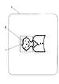
図1は、本発明の実施の形態1に係る撮像装置の構成を示すブロック図である。図2は、本実施の形態に係る撮像装置の概略構成を示す図であり、図2(a)は上面図、図2(b)は背面図を示す。本実施の形態は、カメラブレ補正機能と撮影感度変更機能とを備えるデジタルカメラに適用した例である。なお、以下の説明において、被写体の動き速度(以下、被写体速度ともいう。)とは、カメラブレと被写体ブレとの双方又は一方に起因する、撮像面における被写体の光学像の移動速度を意味する。(Embodiment 1)
FIG. 1 is a block diagram showing a configuration of an imaging apparatus according to
図1において、デジタルカメラ1は、撮像光学系Lと、マイクロコンピュータ3と、撮像センサ4と、CCD(Charge Coupled Device)駆動制御部5と、アナログ信号処理部6と、A/D変換部7と、デジタル信号処理部8と、バッファメモリ9と、画像圧縮部10と、画像記録制御部11と、画像記録部12と、画像表示制御部13と、カメラブレ補正部16と、角速度センサ18と、表示部55と、シャッター制御部41と、シャッター駆動モータ42と、ストロボ制御部43と、ストロボ44と、動き検出部100と、デジタル信号増幅部110と、デジタル信号ゲイン設定部111とを備えて構成される。 In FIG. 1, a
撮像光学系Lは、3つのレンズ群L1、L2、L3を含む光学系である。第1レンズ群L1及び第2レンズ群L2は、光軸方向に移動することによりズーミングを行う。第2レンズ群L2は、補正レンズ群であって、光軸に垂直な面内を移動することにより光軸を偏心させて画像の動きを補正する。第3レンズ群L3は、光軸方向に移動することによりフォーカシングを行う。なお撮像光学系Lは、上記の光学系の構成に限るものではない。 The imaging optical system L is an optical system including three lens groups L1, L2, and L3. The first lens unit L1 and the second lens unit L2 perform zooming by moving in the optical axis direction. The second lens group L2 is a correction lens group and moves in a plane perpendicular to the optical axis to decenter the optical axis and correct image movement. The third lens unit L3 performs focusing by moving in the optical axis direction. The imaging optical system L is not limited to the configuration of the optical system described above.
機械的な振動、撮影者等による揺れ等がデジタルカメラ1に加わると、被写体からレンズに向かって照射される光の光軸とレンズの光軸とにズレが生じるため、不鮮明な画像が形成される。そこで、デジタルカメラ1は不鮮明な画像が形成されるのを防止するためにカメラブレ補正部16及びカメラブレ補正機構20を備える。なお、カメラブレ補正部16及びカメラブレ補正機構20は、撮影者等の揺れやカメラ本体に加わる振動等によって生じる光学像のブレを軽減するものである。 When mechanical vibration or shaking by a photographer or the like is applied to the
撮像センサ4は、撮像光学系Lにより形成される光学的な像を電気的な信号に変換する、例えばCCDセンサである。撮像センサ4は、CCD駆動制御部5により駆動制御される。なお、撮像センサ4はCMOS(Complementary Metal Oxide Semiconductor)センサでもよい。 The
マイクロコンピュータ3は、デジタルカメラ1全体を制御するとともに、被写体の動きに応じてカメラブレ補正機能と撮影感度変更機能とを制御する撮影制御処理を実行する。マイクロコンピュータ3は、被写体速度が所定の閾値より小さい場合には、カメラブレ補正機能を制御してカメラブレ補正を動作させ、被写体速度が所定の閾値以上の場合には、被写体速度が所定の閾値より小さい場合よりも撮影感度変更機能のゲインを高くし更に露出時間を短くするとともに、異なる露出条件により複数枚の画像を連続撮影する。撮影制御処理の詳細については、図6のフローにより後述する。また、マイクロコンピュータ3は、電源スイッチ35、シャッター操作部36、撮影/再生切換操作部37、十字操作キー38、MENU設定操作部39及びSET操作部40の信号を、それぞれ受信可能である。マイクロコンピュータ3は本発明の制御部の一例である。 The
図2において、デジタルカメラ1の筐体1aは、被写体を撮影する際に撮影者等によって支持される。筐体1aの背面には、表示部55と電源スイッチ35と撮影/再生切換操作部37と十字操作キー38とMENU設定操作部39とSET操作部40が設けられている。 In FIG. 2, the
電源スイッチ35は、デジタルカメラ1の電源の入切を行うための操作部材である。撮影/再生切換操作部37は、撮影モード又は再生モードに切換えるための操作部材であり、撮影者等はレバーを回動させて切換えることができる。MENU設定操作部39は、デジタルカメラ1の各種動作を設定するための操作部材である。十字操作キー38は、撮影者等が上下左右の部位を押圧して、表示部55に表示された各種メニュー画面から所望のメニューを選択するための操作部材である。SET操作部40は、各種メニュー表示を1つ前の表示に戻すための操作部材である。 The
図2(b)において、筐体1aの上面には、シャッター操作部36とズーム操作部57が設けられる。ズーム操作部57は、シャッター操作部36の周囲に設けられ、シャッター操作部36と同軸に回動可能である。撮影者等が撮影/再生切換操作部37を操作して撮影モードに切換えた後、ズーム操作部57を右方向に回動させるとレンズ群は望遠側に移動し、左方向に回動させるとレンズ群は広角側に移動する。 In FIG. 2B, a
シャッター操作部36は、撮影の際に撮影者等によって操作される、例えばレリーズボタンである。シャッター操作部36が操作されると、タイミング信号がマイクロコンピュータ3に出力される。シャッター操作部36は、半押し操作と全押し操作が可能な二段式の押下スイッチであり、撮影者等が半押し操作すると後述する被写体の動き検出、測光処理及び測距処理を開始する。続いて撮影者等が全押し操作するとタイミング信号が出力される。シャッター制御部41は、タイミング信号を受信したマイクロコンピュータ3から出力される制御信号にしたがって、シャッター駆動モータ42を駆動し、シャッターを動作させる。 The
再び図1に戻り、デジタルカメラ1の構成の説明を続ける。図1中、ストロボ制御部43は、ストロボ44の動作を制御する。シャッター操作部36の操作によるタイミング信号を受信したマイクロコンピュータ3は、ストロボ制御部43に制御信号を出力する。そしてストロボ制御部43は、制御信号に基づいてストロボ44を発光させる。ストロボ44は、撮像センサ4が受光する光量に応じて制御される。すなわち、ストロボ制御部43は、撮像センサ4からの画像信号の出力が一定値以下の場合にはシャッター動作と連動して自動的に発光させる。一方、画像信号の出力が一定値以上の場合には、ストロボ制御部43はストロボ44を発光させないように制御する。 Returning to FIG. 1 again, the description of the configuration of the
ストロボ入/切操作部56は、上述の撮像センサ4の出力に関係なくストロボ44の動作を設定するための操作部である。すなわち、ストロボ制御部43は、ストロボ入/切操作部56が「入」の場合にはストロボ44を発光させ、「切」の場合にはストロボ44を発光しない。 The strobe on / off
撮像センサ4から出力された画像信号は、アナログ信号処理部6から、A/D変換部7、デジタル信号処理部8、バッファメモリ9、画像圧縮部10へと、順次送られて処理される。アナログ信号処理部6は、撮像センサ4から出力される画像信号にガンマ処理等のアナログ信号処理を施す。A/D変換部7は、アナログ信号処理部6から出力されたアナログ信号をデジタル信号に変換する。デジタル信号処理部8は、A/D変換部7によりデジタル信号に変換された画像信号に対してノイズ除去や輪郭強調等のデジタル信号処理を施し、動き検出部100及びデジタル信号増幅部110に出力する。バッファメモリ9は、RAM(Random Access Memory)であり、画像信号を一旦記憶する。 The image signal output from the
デジタル信号ゲイン設定部111は、デジタル信号処理された画像信号の増幅ゲインを設定する。デジタル信号増幅部110は、設定された増幅ゲインで画像信号を増幅し、バッファメモリ9に出力する。なお、増幅ゲインの設定は撮影感度の設定に対応する。本実施の形態では、撮影感度はISO感度に相当する値として表され、例えばISO80、100、200、400、800、1600相当の撮影感度に設定可能である。なお、設定可能な撮影感度はこれに限られない。また、撮影感度はISO感度相当以外の値で表されてもよい。 The digital signal
また、画像信号を増幅する処理は、デジタル信号増幅部110において行われる場合に限られず、アナログ信号処理部6にてアナログ信号に対して行ってもよい。また増幅処理は、撮像センサ4にて行われてもよい。 Further, the process of amplifying the image signal is not limited to being performed in the
バッファメモリ9に記憶された画像信号は、画像圧縮部10から画像記録部12へと、順次送られて処理される。バッファメモリ9に記憶された画像信号は、画像記録制御部11の指令により読み出されて、画像圧縮部10に送信される。画像圧縮部10に送信された画像信号のデータは、画像記録制御部11の指令に従って画像信号に圧縮処理される。画像信号は、この圧縮処理により、元のデータより小さなデータサイズになる。かかる圧縮方法として、例えばJPEG(Joint Photographic Experts Group)方式が用いられる。その後、圧縮された画像信号は、画像記録制御部11により画像記録部12に記録される。 The image signals stored in the
画像記録部12は、画像記録制御部11の指令に基づいて、画像信号と記録すべき所定の情報とを関連付けて記録する、例えば内部メモリ及び/又は着脱可能なリムーバブルメモリである。なお、画像信号とともに記録すべき所定の情報には、画像を撮影した際の日時と、焦点距離情報と、シャッタースピード情報と、絞り値情報と、撮影モード情報とが含まれ、例えばExif(登録商標)形式やExif(登録商標)形式に類する形式である。 The
表示部55は、画像表示制御部13からの指令に基づいて、画像記録部12あるいはバッファメモリ9に記録された画像信号を可視画像として表示する。ここで表示部55の表示形態としては、画像信号のみを可視画像として表示する表示形態と、画像信号と撮影時の情報とを可視画像として表示する表示形態とがある。動き検出部100は、デジタル信号に変換された画像信号に基づいてフレーム間の画像の水平・垂直方向の位置ずれ量を示すベクトル(以下、動きベクトルという)をフレーム毎に検出する。以下、動き検出部100の詳細について説明する。 The
図3は、上記動き検出部100の構成の一例を示すブロック図である。図3において、動き検出部100は、代表点記憶部101と、相関演算部102と、動きベクトル検出部103とを含んで構成される。 FIG. 3 is a block diagram illustrating an example of the configuration of the
代表点記憶部101は、A/D変換部7及びデジタル信号処理部8を経て入力される現フレームの画像信号を複数の領域に分割し、各領域に含まれる特定の代表点に対応する画像信号を代表点信号として記憶する。また、代表点記憶部101は、既に記憶されている現フレームよりも1フレーム前の代表点信号を読み出して相関演算部102に出力する。 The representative
相関演算部102は、1フレーム前の代表点信号と現フレームの代表点信号間の相関演算を行い、代表点信号間の差を比較する。演算結果は動きベクトル検出部103に出力される。 The
動きベクトル検出部103は、相関演算部102による演算結果から1フレーム前と現フレーム間の画像の動きベクトルを1画素単位で検出する。そして動きベクトルは、マイクロコンピュータ3に出力される。マイクロコンピュータ3は、動きベクトルに対するゲイン及び位相などを調整し、画像信号上の被写体の単位時間あたりの動き速度及び方向を算出する。 The motion
被写体の動きを検出する処理は、例えば撮影者等がシャッター操作部36を半押し操作することにより開始される。なお、処理の開始は、撮影者等が電源スイッチ35をONにした後、撮影/再生切換操作部37を操作して撮影モードに切り替える動作と連動させてもよい。 The process of detecting the movement of the subject is started, for example, when a photographer or the like presses the
次に、カメラブレ補正機能を実現するカメラブレ補正部16の構成について説明する。カメラブレ補正部16は、位置検出部15と、ヨーイング駆動制御部14xと、ピッチング駆動制御部14yと、D/A変換部17x、17y、角速度センサ18x、18yと、A/D変換部19x、19yとを含む。 Next, the configuration of the camera shake correction unit 16 that realizes the camera shake correction function will be described. The camera shake correction unit 16 includes a
ヨーイング駆動制御部14x及びピッチング駆動制御部14yは、補正レンズ群L2を撮像光学系Lの光軸AXに直交する2方向に駆動させる。位置検出部15は、補正レンズ群L2の位置を検出する。以上の位置検出部15とヨーイング駆動制御部14xとピッチング駆動制御部14yは、補正レンズ群L2を駆動制御するための帰還制御ループを形成している。 The yawing
角速度センサ18x、18yは、撮像光学系Lを含むデジタルカメラ1自体の動きを検出するセンサである。角速度センサ18x、18yは、デジタルカメラ1が静止している状態での出力を基準として、デジタルカメラが動く方向に応じて正負の角速度信号を出力する。なお、本実施の形態では、ヨーイング方向及びピッチング方向の2方向を検出するために角速度センサを2個設けている。 The
出力された角速度信号は、フィルタ処理、アンプ処理等を経て、A/D変換部19x、19yによりデジタル信号に変換されてマイクロコンピュータ3に与えられる。そして、マイクロコンピュータ3は、角速度信号に対してフィルタリング、積分処理、位相補償、ゲイン調整、クリップ処理等を順次施して、カメラブレ補正に必要なレンズ群L2の駆動制御量を算出し、制御信号として出力する。かかる制御信号は、D/A変換部17x、17yを介してヨーイング駆動制御部14x、ピッチング駆動制御部14yに出力される。 The output angular velocity signal is subjected to filter processing, amplifier processing, and the like, converted into a digital signal by the A /
ヨーイング駆動制御部14x及びピッチング駆動制御部14yは、制御信号に基づいて補正レンズ群L2を所定の駆動量だけ駆動させる。これにより、カメラブレを補正し、画質劣化を軽減することができる。 The yawing
図4は、上記カメラブレ補正部16に含まれるカメラブレ補正機構20の構成を示す分解斜視図である。 FIG. 4 is an exploded perspective view showing the configuration of the camera
カメラブレ補正機構20は、ピッチング移動枠21と、ヨーイング移動枠22、ピッチングシャフト23a、23bと、コイル24x、24yと、固定枠25と、ヨーイングシャフト26a、26bと、マグネット27x、27yと、ヨーク28x、28yと、アクチュエータ29x、29yと、発光素子30と、受光素子31とを中心に構成される。 The camera
補正レンズ群L2は、ピッチング移動枠21に固定される。ピッチング移動枠21は、ヨーイング移動枠22に対して2本のピッチングシャフト23a、23bを介してY方向に摺動可能に保持される。また、ピッチング移動枠21には、コイル24x、24yが固定される。ヨーイング移動枠22は、固定枠25に対してヨーイングシャフト26a、26bを介してX方向に摺動可能に保持される。マグネット27xとヨーク28xとは固定枠25に保持され、コイル24xとともにアクチュエータ29xを構成する。同様に、マグネット27yとヨーク28yとは固定枠25に保持され、コイル24yとともにアクチュエータ29yを構成する。発光素子30は、ピッチング移動枠21に固定される。また、受光素子31は、固定枠25に固定され、発光素子30の投射光を受光して2次元の位置座標を検出する。かかる発光素子30と受光素子31とは、上述の位置検出部15を構成する。 The correction lens group L2 is fixed to the
以下、上述のように構成されたカメラブレ補正機能と撮影感度変更機能とを備えるデジタルカメラ1の動作を説明する。 Hereinafter, an operation of the
まず、デジタルカメラ1において選択可能な撮影モードについて説明する。撮影モードには、例えば0.3秒間隔でシャッター駆動モータ42を動作させて2回又は複数回の連続撮影を行う「連写モード」や、後述する「感度アップ&カメラブレ補正自動選択モード」、「感度アップモード」、「カメラブレ補正モード」等が含まれ、撮影者等は所望の撮影モードを選択可能である。撮影モードが選択されると、マイクロコンピュータ3は各撮影モードに応じて各種制御部を制御する。 First, photographing modes that can be selected in the
図5は、表示部55に表示された撮影モード選択画面の表示例を示す図である。撮影モード選択画面は、撮影者等がMENU設定操作部39や十字操作キー38を操作することにより、表示部55に表示させることができる。図5に示すように、撮影モードは、「感度アップ&カメラブレ補正自動選択モード」と、「感度アップモード」と、「カメラブレ補正モード」と、「モードOFF」からなり、撮影者等はそれぞれ対応するアイコン90〜93を選択することにより所望の撮影モードに設定することができる。なお、図5には本実施の形態において特徴的な撮影モード選択アイコンのみが表示されているが、前述した「連写モード」等、他の撮影モード選択アイコンをさらに表示してもよい。 FIG. 5 is a diagram illustrating a display example of the shooting mode selection screen displayed on the
感度アップモード選択アイコン91が選択されると、通常の撮影よりも高感度の撮影感度に変更される(「感度アップモード」)。すなわち、デジタル信号増幅部110はマイクロコンピュータ3からの指令により画像信号を所定のゲインで増幅する。これにより、露光時間を短くし、速いシャッタースピードで撮影することができるので、像ブレの影響を小さくすることができる。 When the sensitivity up
カメラブレ補正モード選択アイコン92が選択されると、カメラブレ補正機能が動作する(「カメラブレ補正モード」)。すなわち、カメラブレ補正機構20は、マイクロコンピュータ3からの指令により補正レンズ群L2を光軸と直交する平面内の2方向に駆動させてカメラブレを軽減する。 When the camera shake correction
感度アップ&カメラブレ補正自動選択モードアイコン90が選択されると、マイクロコンピュータ3は、被写体の動く速度に応じて、「感度アップモード」又は「カメラブレ補正モード」のいずれかに自動的に切り替える。これにより、被写体が被写体ブレを発生させるような速度で動く場合には高感度の撮影感度に設定され、一方、被写体が被写体ブレを発生させないような遅い速度で移動する場合にはカメラブレによる像ブレを軽減するカメラブレ補正機能が動作する。 When the sensitivity up & camera shake correction automatic
モードOFF選択アイコン93が選択されると、上記の撮影感度アップ機能及びカメラブレ補正機能は動作せず、通常モードにて通常の撮影が可能である。 When the mode
次に、「感度アップ&カメラブレ補正自動選択モード」が選択された場合の撮影処理について、図6のフローチャートを用いて説明する。 Next, shooting processing when “sensitivity increase & camera shake correction automatic selection mode” is selected will be described with reference to the flowchart of FIG.
図6は、デジタルカメラ1の撮影処理を示すフローチャートであり、マイクロコンピュータ3により実行される。本フローは、例えばデジタルカメラ1の電源スイッチ35がON側に操作されると開始する。 FIG. 6 is a flowchart showing the photographing process of the
Step1の処理では、撮影者等がデジタルカメラ1の筐体1aの背面側に設けられたMENU設定操作部39を操作すると表示部55には撮影モードの一覧が表示される。表示された撮影モード選択アイコンのうち、撮影者等が感度アップ&カメラブレ補正自動選択モードアイコン90を選択すると、処理はStep2に進み、「カメラブレ補正モード」が始まる。 In
Step2では、マイクロコンピュータ3は撮影モードを「カメラブレ補正モード」に切り替え、カメラブレ補正部16及びカメラブレ補正機構20を動作させる。カメラブレ補正部16は、角速度センサ18x、18yによりカメラ本体に加わるカメラブレなどのカメラブレを検知する。そしてマイクロコンピュータ3からの指令により、外部の回路からピッチング移動枠21のコイル24x、24yに電流が供給され、アクチュエータ27x、27yが形成する磁気回路により、ピッチング移動枠21及び補正レンズ群L2は光軸AXと直交する平面内の2方向X、Y方向に移動する。このとき、受光素子29はピッチング移動枠21の位置を検出するので、高精度な位置検出が可能である。 In
Step3では、撮影者等がシャッター操作部36を操作したことを認識して、マイクロコンピュータ3は処理をStep4へ移行させる。 In
Step4では、被写体の顔検出を行う。顔検方法としては、撮影画像から輪郭情報を検出し、検出された輪郭内に特徴点(目、鼻、口等)が存在するかを検出する方法がある。顔検出部120は、検出された輪郭内に特徴点が存在する場合、顔と判断する。 In
Step5では、被写体の顔の動きを検出する。顔の動き検出処理では、動き検出部100が撮影対象となる被写体の動きを、撮影画像の代表点を追跡することにより検出し、動きベクトルを出力する。また、動き検出処理と同時に測光処理及び測距処理を行う。測光処理では、デジタル信号処理部8は、撮像センサ4により出力された画像信号に基づいて露光値を演算する。マイクロコンピュータ3は、演算された露光値に基づいて適切なシャッタースピードを自動設定する。また、測距処理では、図示しないフォーカス制御部は画像信号のコントラスト値がピークとなるようにレンズ群を光軸方向に移動させ合焦調整を行う。また、被写体として顔を検出できなかった場合には、「感度アップ&カメラブレ補正自動選択モード」を抜け、通常の「カメラブレ補正モード」での撮影を継続する。 In
また、被写体の顔の動き検出する際には、カメラブレ補正を行っているため、カメラブレの影響を少なくした状態によって、動き検出を行うことができるので、動き検出の精度を高めることができる。つまり、撮像センサ4での像の動きが、被写体の動きによるものであるか、撮影者等のカメラブレによるカメラ本体の動きの影響であるのかどうかを区別できる。 In addition, since the camera shake correction is performed when detecting the motion of the face of the subject, the motion detection can be performed in a state where the influence of the camera shake is reduced, so that the accuracy of the motion detection can be improved. That is, it is possible to distinguish whether the image movement at the
Step6では、マイクロコンピュータ3は動き検出部100により検出された動きベクトルから、単位時間あたりの被写体の顔の動き速度Vhを算出する。 In
Step7では、動き速度Vhの判定処理を行う。デジタルカメラ1には予め所定の値Aが設定されており、マイクロコンピュータ3は動き速度Vhと所定の値Aとを比較する。ここで、所定の値Aは被写体ブレが生じる閾値となる値であり、カメラ固有の値であってもよいし、撮影者等により任意に設定されてもよい。例えば、ストロボを使用する時には、シャッタースピードを速くすることができるので、閾値を大きくすることにより、むやみに撮影感度が上がることがない。逆に、被写体として動きやすい子供やペットを撮影する際には、デジタルカメラ1に、別途子供撮影モードあるいはペット撮影モードを設けることにより、撮影者等がそのモードが選択した時には、閾値を小さくして、撮影感度をアップさせることを優先するような方法であってもよい。さらには、被写体までの距離が遠くてストロボ光が届かない、あるいはデジタルカメラ1の焦点距離が長くてカメラブレの影響が大きい場合にも、閾値を小さくして、撮影感度を優先させてもよい。比較の結果、動き速度Vhが値A以上の場合、マイクロコンピュータ3は被写体が被写体ブレを発生させる速度で動いていると判断し、処理をStep12移行させる。動き速度Vhが値Aよりも小さい場合、マイクロコンピュータ3は、被写体ブレは発生しないと判断して、処理をStep8へ移行させる。被写体ブレが発生しない状況においては、撮影感度であるISO感度を64相当とし、シャッタースピード1/30秒等に設定する。 In Step 7, the determination process of the movement speed Vh is performed. A predetermined value A is set in advance in the
Step8では、マイクロコンピュータ3は撮影モードとして「カメラブレ補正モード」を継続し、カメラブレ補正部16及びカメラブレ補正機構20を動作させる。カメラブレ補正部16は、角速度センサ18x、18yによりカメラ本体に加わるブレを検知する。そしてマイクロコンピュータ3からの指令により、外部の回路からピッチング移動枠21のコイル24x、24yに電流が供給され、アクチュエータ27x、27yが形成する磁気回路により、ピッチング移動枠21及び補正レンズ群L2は光軸AXと直交する平面内の2方向X、Y方向に移動する。このとき、受光素子29はピッチング移動枠21の位置を検出するので、高精度な位置検出が可能である。 In
Step9では、マイクロコンピュータ3は撮影者等がシャッター操作部36を全押し操作したことを認識すると、Step10で撮影処理を行う。すなわち、撮像センサ4上に被写体像が形成されて画像信号が出力され、出力された画像信号は、表示部55に表示される。 In
Step11では、画像信号を画像記録部12に記録して、撮影処理を終了する。また、画像信号を記録する際、撮影画像全体に対する測距エリアFaの位置も同時に記録する。なお撮影については、1枚の撮影に限らず、連続撮影を行ってもよい。 In
図7は、「カメラブレ補正モード」により撮影された撮影画像を表示部55に表示する表示例を示す図である。図7に示すように、表示部55には撮影画像とともに撮影感度であるISO感度を表示する。 FIG. 7 is a diagram illustrating a display example in which a captured image captured in the “camera shake correction mode” is displayed on the
このように、被写体の顔の動き速度Vhが所定の値Aよりも小さい場合には、撮影感度は変更されずに、カメラブレ補正機能が動作する。これにより、カメラブレによるカメラブレを軽減し、良好な画質の画像を撮影することができる。 Thus, when the moving speed Vh of the subject's face is smaller than the predetermined value A, the camera shake correction function operates without changing the shooting sensitivity. Thereby, camera shake due to camera shake can be reduced, and an image with good image quality can be taken.
一方、上記Step7で動き速度Vhが値A以上の場合、Step12でマイクロコンピュータ3は撮影モードを「感度アップモード」に切り替える。すなわち、デジタル信号ゲイン設定部111は、高感度の撮影感度となるようゲインを設定する。こここでマイクロコンピュータ3は、被写体の顔の動き速度に応じて撮影感度が設定される。よって、被写体の顔の動き速度Vhから被写体ブレの生じないシャッタースピードを算出し、かかるシャッタースピードにて撮影可能な撮影感度に設定する。例えば、屋外の環境下で、歩く速度でゆっくりと移動する被写体を撮影する場合にはISO感度100相当の撮影感度に設定され、走る速度で移動する被写体を撮影する場合にはISO感度400相当の撮影感度に設定されるなど被写体の顔の動き速度に応じて撮影感度が設定される。 On the other hand, if the movement speed Vh is greater than or equal to the value A in Step 7, the
Step13では、マイクロコンピュータ3は撮影者がシャッター操作部を全押し操作されたことを認識すると、Step14以下で撮影処理を行う。すなわち、Step14では、被写体の光学的な像が撮像センサ4上に形成され、撮像センサ4は画像信号を出力する。そしてデジタル信号増幅部110は、デジタル信号処理部8から出力された画像信号に対し、上記Step12において設定されたゲインで増幅する。 In
Step15では、増幅された画像信号を画像記録部12に記録して、撮影処理を終了する。また、画像信号を記録する際、撮影画像全体に対する測距エリアFaの位置も同時に記録する。なお撮影については、1枚の撮影に限らず、連続撮影を行ってもよい。 In
図7は、「カメラブレ補正モード」により撮影された撮影画像を表示部55に表示する表示例を示す図である。図7に示すように、表示部55には撮影画像とともに撮影感度であるISO感度を表示する。 FIG. 7 is a diagram illustrating a display example in which a captured image captured in the “camera shake correction mode” is displayed on the
このように、被写体の顔の動き速度Vhが所定の値A以上の場合には、高感度の撮影感度に設定される。これにより露光時間を短くすることができ、速いシャッタースピードでの撮影が可能となるので、被写体ブレを防ぐことができる。なお、撮影感度アップモードにおいては、カメラブレ補正機構を動作させる、動作させない、のいずれであってもよい。 As described above, when the moving speed Vh of the subject's face is equal to or higher than the predetermined value A, the shooting sensitivity is set to high sensitivity. As a result, the exposure time can be shortened, and shooting at a high shutter speed is possible, so that subject blurring can be prevented. In the shooting sensitivity increase mode, either the camera shake correction mechanism may be operated or may not be operated.
以上のように、本実施の形態によれば、検出された被写体の顔の動きに基づいて被写体速度を算出し、被写体速度が所定の閾値A以上か否かを判別し、被写体速度が閾値Aより小さい場合には、カメラブレ補正部16を制御してカメラブレ補正を動作させ、被写体速度が閾値A以上の場合には、デジタル信号ゲイン設定部111のゲインを高くしてISO感度をアップ、及び/又は、シャッター速度を速くして露出時間を短くするので、カメラブレや被写体ブレによる画質劣化を軽減することができ、良好な画質の画像を容易に撮影することができる。 As described above, according to the present embodiment, the subject speed is calculated based on the detected movement of the face of the subject, it is determined whether the subject speed is equal to or higher than the predetermined threshold A, and the subject speed is the threshold A. If it is smaller, the camera shake correction unit 16 is controlled to operate camera shake correction. If the subject speed is equal to or higher than the threshold A, the gain of the digital signal
具体的には、被写体の顔の動きが速い場合には高感度の撮影感度に変更し、露光時間を短くして高速のシャッタースピードで撮影する。これにより被写体ブレによる画質劣化を防ぐことができる。また、被写体の顔の動きが遅い場合にはカメラブレ補正部16を動作させるので、カメラブレによるカメラブレを防ぎ、画質劣化を軽減することができる。したがって、撮影者は被写体の動きによらず、簡単に撮影することが可能となる。 Specifically, when the movement of the face of the subject is fast, the shooting sensitivity is changed to a high sensitivity, and the exposure time is shortened and the image is shot at a high shutter speed. Thereby, it is possible to prevent image quality deterioration due to subject blurring. Further, when the movement of the subject's face is slow, the camera shake correction unit 16 is operated, so that camera shake due to camera shake can be prevented and image quality deterioration can be reduced. Therefore, the photographer can easily shoot regardless of the movement of the subject.
また、被写体の顔の動きが速い場合には自動的に高感度の撮影感度に変更するので、撮影者等は被写体の動きを観察して被写体ブレが発生するか否かについて判断する必要がなく利便性が高い。 In addition, when the subject's face moves quickly, it automatically changes to a high sensitivity, so there is no need for the photographer to observe the subject's movement and determine whether subject blur occurs. Convenience is high.
また、本実施の形態では、検出した被写体速度が閾値A以上の場合に高感度の撮影感度に変更する。これにより、被写体が被写体ブレを発生させない速度で動いているにもかかわらず、撮影者等が誤って高感度の撮影感度に設定することがない。 In the present embodiment, when the detected subject speed is equal to or higher than the threshold A, the shooting sensitivity is changed to high sensitivity. Thus, even though the subject is moving at a speed that does not cause subject blurring, a photographer or the like does not accidentally set a high sensitivity.
特に、本実施の形態では、被写体の動き全体を検出するのではなく、被写体の動きの中でも被写体の顔の動きに着目し、被写体の顔の動きが遅い場合にはカメラブレ補正部16を動作させ、被写体の顔の動きが速い場合には高感度の撮影感度に変更するので、撮影者等が最も良好に撮影したいと考えられる被写体の顔の動きに合わせて、カメラブレ補正制御から高感度の撮影感度制御に切替えることができる。したがって、検出した被写体の一部又は全部の動き速度が閾値A以上であっても、被写体の顔の動きが閾値Aより小さければ、「カメラブレ補正モード」を継続し、「感度アップモード」に変更しない。すなわち、被写体の顔の動きが閾値A以上になるまでは、「カメラブレ補正モード」をできるだけ継続して、被写体の顔の動きが閾値A以上になって初めて「感度アップモード」に移行する。例えば、被写体が人で、その人が手を振っている場合など、被写体の顔の動きがそれ程ないような状況下では、「感度アップモード」に移行せず、むやみに撮影感度を上げることが防止される。これにより、被写体速度が遅い場合にISO感度をアップさせた場合に発生する画質の劣化を防ぐことができる。撮影者等は、顔が撮れれば一番良いと想定されるので、顔が動かなければISO感度をアップさせない。本制御は、ユーザが図5に示す撮影モード選択画面によって設定/解除は容易に行える。また、この撮影モード選択画面にさらに、被写体の動きによって高感度の撮影感度に変更するメニューを付加してもよい。 In particular, the present embodiment does not detect the entire movement of the subject but focuses on the movement of the subject's face among the movements of the subject, and operates the camera shake correction unit 16 when the movement of the subject's face is slow. If the subject's face moves quickly, the sensitivity is changed to a high-sensitivity shooting sensitivity. It can be switched to sensitivity control. Therefore, even if the motion speed of a part or all of the detected subject is equal to or higher than the threshold A, if the subject's face motion is smaller than the threshold A, the “camera shake correction mode” is continued and changed to the “sensitivity up mode”. do not do. In other words, the “camera shake correction mode” is continued as much as possible until the movement of the subject's face exceeds the threshold A, and the “sensitivity increase mode” is entered only when the movement of the subject's face exceeds the threshold A. For example, when the subject is a person and the person is waving, the shooting sensitivity may be increased unnecessarily without shifting to the `` sensitivity up mode '' in situations where the subject's face does not move much. Is prevented. Thereby, it is possible to prevent the deterioration of the image quality that occurs when the ISO sensitivity is increased when the subject speed is low. It is assumed that the photographer is best if the face can be taken, so the ISO sensitivity is not increased unless the face moves. This control can be easily set / released by the user through the shooting mode selection screen shown in FIG. In addition, a menu for changing to a high sensitivity according to the movement of the subject may be added to the shooting mode selection screen.
本実施の形態の撮像制御が威力を発揮するのは、運動会での望遠撮影時などの使用に特に有効である。被写体の顔の動きを検出して撮影感度を決めることにより、例えば、被写体の手、あるいは足などが動いても、むやみに撮影感度を上げる必要がなくなるので、撮影感度を上げることによる画質の劣化を防ぐことができる。 The fact that the imaging control of the present embodiment is effective is particularly effective when used for telephoto shooting at an athletic meet. By detecting the movement of the subject's face and determining the shooting sensitivity, for example, even if the subject's hand or foot moves, there is no need to increase the shooting sensitivity unnecessarily. Can be prevented.
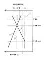
ここで、「シャッター半押し動作」から「シャッター全押し動作」を経て撮影に至るまでに被写体の速度変化と撮影感度の関係について説明する。 Here, the relationship between the change in the speed of the subject and the shooting sensitivity from the “shutter half-pressing operation” to the “shutter full-pressing operation” to the shooting will be described.
図8は、被写体の動き速度Vhと撮影時の撮影感度Sの関係を説明する図である。図8中、T1は半押し動作、T2は全押し動作、T3は撮影の各タイミングである。また、S1〜S4は撮影時の撮影感度、Aは所定の閾値である。被写体速度Vhが所定の閾値A以上か否かを判別し、被写体速度が閾値Aより小さい場合には、カメラブレ補正部16を、また被写体速度Vhが閾値A以上の場合には、ISO感度をアップ及びシャッター速度を速くする。 FIG. 8 is a diagram for explaining the relationship between the moving speed Vh of the subject and the photographing sensitivity S at the time of photographing. In FIG. 8, T1 is a half-pressing operation, T2 is a full-pressing operation, and T3 is each timing of photographing. S1 to S4 are photographing sensitivity at the time of photographing, and A is a predetermined threshold value. It is determined whether the subject speed Vh is equal to or higher than a predetermined threshold A. If the subject speed is lower than the threshold A, the camera shake correction unit 16 is increased. If the subject speed Vh is higher than the threshold A, the ISO sensitivity is increased. And increase the shutter speed.
本実施の形態では、「シャッター半押し動作」と連動して、被写体の動きベクトル検出を開始する(図6のフローのStep4)。そして、「シャッター全押し動作」の直前まで(図6のフローのStep8,Step12)、一定期間毎に動きベクトル検出を行い、「シャッター全押し動作」時の速度を、最終の被写体速度Vhとする。この場合、図8(1)は被写体に動きがない時、(2)は等速で移動している時、(3)は被写体が一定割合で加速している時、(4)は被写体が一定割合で減速している時であるとすると、被写体の速度変化と撮影感度の関係は以下のようになる。 In the present embodiment, the motion vector detection of the subject is started in conjunction with the “shutter half-pressing operation” (
(1)「シャッター半押し動作」中の被写体速度Vhが、閾値Aより低く一定の場合
被写体速度Vhが所定の閾値Aより低いので、撮影感度アップは行わず、撮影感度S1とする。(1) When the subject speed Vh during the “shutter half-pressing operation” is lower than the threshold value A and constant The subject speed Vh is lower than the predetermined threshold value A, so the shooting sensitivity is not increased and the shooting sensitivity S1 is set.
(2)「シャッター半押し動作」中の被写体速度Vhが、閾値Aより高く一定の場合
「シャッター全押し動作」時の被写体速度Vhに応じて、撮影感度アップし、ここでは撮影感度S2に設定する。(2) When the subject speed Vh during the “half-pressing operation of the shutter” is higher than the threshold A and is constant, the shooting sensitivity is increased according to the subject speed Vh during the “full-pressing operation of the shutter”, and here, the shooting sensitivity S2 is set. To do.
(3)「シャッター半押し動作」中の被写体速度Vhが、所定の閾値Aを超え、徐々に速度が速くなる場合
徐々に被写体速度Vhが速くなるので、加速度を計算し、「シャッター全押し動作」時から実際の撮影時までのタイムラグの時間分のみ、速度が速くなる分を予測して感度を撮影感度S3(S2<S3)に設定する。(3) When the subject speed Vh during “shutter half-pressing operation” exceeds a predetermined threshold A and the speed gradually increases Since the subject speed Vh gradually increases, the acceleration is calculated and the “shutter full-pressing operation” The sensitivity is set to the shooting sensitivity S3 (S2 <S3) by predicting the speed increase only for the time lag from the time of shooting to the time of actual shooting.
(4)「シャッター半押し動作」中の被写体速度Vhが、所定の閾値Aを超え、徐々に遅くなる場合
上記(3)の場合とは逆に、被写体速度Vhが徐々に遅くなる場合には、速度が遅くなる分を予測して感度を撮影感度S4(S4<S2)に設定する。(4) When the subject speed Vh during the “shutter half-pressing operation” exceeds the predetermined threshold A and gradually decreases When the subject speed Vh gradually decreases, contrary to the case of (3) above. The sensitivity is set to the photographing sensitivity S4 (S4 <S2) by predicting the amount of slowing down.
図9は、本実施の形態に係る撮像装置の「撮影感度アップモード」設定後感度アップあり撮影画像と感度アップなし撮影画像とを表示部に表示する表示例を示す図である。 FIG. 9 is a diagram illustrating a display example in which a captured image with increased sensitivity and a captured image without increased sensitivity are displayed on the display unit after the “imaging sensitivity increased mode” setting of the imaging apparatus according to the present embodiment.
また、図9に示すように、1回のシャッター操作により連写し、感度アップあり画像と、感度アップなし画像とを異なる撮影感度にて撮影することにより、撮影後すぐ、あるいは再生時に、簡単に2つのモードの撮影画像、画質を比較できるようにしてもよい。さらには、画像を自動的に、あるいは十字操作キー38などにて手動で拡大表示することにより、併せて4枚の撮影画像を表示部55に同時に表示させてもよい。 In addition, as shown in FIG. 9, continuous shooting is performed with a single shutter operation, and images with increased sensitivity and images without increased sensitivity are captured at different shooting sensitivities, so that it is easy to perform immediately after shooting or during playback. You may enable it to compare the picked-up image and image quality of two modes. Furthermore, four captured images may be displayed simultaneously on the
さらには、2つの撮影画像を記録する際に、2つとも記録させる、あるいは撮影者等が任意の画像を選択し、必要のない画像を消去できるようにしてもよい。 Furthermore, when recording two captured images, both of them may be recorded, or a photographer or the like may select an arbitrary image and delete an unnecessary image.
また、撮影画像の再生時には、撮影画像全体を表示させる他、撮影画像に記録された測距領域Faを中心に任意の倍率にて拡大表示できるようにしてもよい。 In addition, when the captured image is reproduced, the entire captured image may be displayed, and the enlarged image may be displayed at an arbitrary magnification centering on the distance measurement area Fa recorded in the captured image.
また、撮影感度については、撮影画質の劣化を抑えるために、上限を設定できるようにしてもよい。 Further, an upper limit may be set for the shooting sensitivity in order to suppress the deterioration of the shooting image quality.
また、セルフタイマーを用いた撮影時などでは、シャッター操作部36を全押しした後、撮影が開始されるまでの数秒前から、被写体の光学像の動きを検出できるようにしてもよい。なお、動きを検出している際には、被写体側から認識できるように、デジタルカメラ1の前面に設けられたLEDなどにて、点滅させるようにすればなおさらよい。 Further, at the time of shooting using the self-timer, the movement of the optical image of the subject may be detected from several seconds before the shooting is started after the
(実施の形態2)
実施の形態2は、複数の被写体の顔の動きを検出して撮影モードを設定する例について説明する。(Embodiment 2)
The second embodiment will describe an example in which the shooting mode is set by detecting the movement of the faces of a plurality of subjects.
本発明の実施の形態2に係る撮像装置のハード的構成は、図1乃至図3とほぼ同様であるため説明を省略する。 The hardware configuration of the imaging apparatus according to
本実施の形態に係るデジタルカメラは、複数の被写体より任意の被写体を選択し、その選択された被写体の顔の動きを検出して、撮影モードを選択可能とする点が実施の形態1のデジタルカメラと異なる。以下、実施の形態1と同一の構成要素については同一の符号を付し、実施の形態1と異なる点を中心に説明する。 The digital camera according to the present embodiment is such that an arbitrary subject is selected from a plurality of subjects, the movement of the face of the selected subject is detected, and a shooting mode can be selected. Different from the camera. Hereinafter, the same components as those in the first embodiment will be denoted by the same reference numerals, and different points from the first embodiment will be mainly described.
図10は、撮影する際の顔検出処理時の様子を表示部55に表示する表示例を示す図である。図10中、複数の被写体の人物a、人物b、人物cに対して、顔検出処理を行った撮影画面上の所定位置に、測距エリア枠Fa、Fb、Fcが設定される。この場合、測距エリアは優先的に割り当てられる。本実施の形態では、優先される測距エリアは実線により表示され、それ以外は破線により表示される。また、被写体の動き検出については、実線により表示された測距エリアが優先される。 FIG. 10 is a diagram illustrating a display example in which a state at the time of face detection processing at the time of shooting is displayed on the
図10では、人物aの顔に実線の測距エリアが設定されているため、動き検出については、人物aの顔の動きが優先される。また測距エリアの優先度については、自動的に真ん中の被写体に設定される、あるいは撮影者等により自由に選択できるようにしてもよい。撮影者等が選択する場合には、十字操作キー38の左右部位を押圧することにより、優先する測距エリアを移動させることが可能である。十字操作キー38の左部を押圧すると、優先する人物が人物bに変更され、測距エリアFbが実線に変わる。また、十字操作キー38の右部を押圧すると、優先する人物が人物cに変更され、測距エリアFcが実線に変わる。さらには、優先する被写体については、デジタルカメラ1が予め特定の人物の顔情報を記憶し、検出した顔と、記録された顔情報とが一致した場合には、その人物を自動的に優先するようなシステムであってもよく、撮影者等の子供の写真を撮る際などに非常に有効である。なお測距エリアについては、3箇所に限らず、それ以上であってもよい。 In FIG. 10, since the solid line ranging area is set on the face of the person a, the movement of the face of the person a is prioritized for motion detection. The priority of the distance measurement area may be automatically set to the middle subject or may be freely selected by the photographer. When the photographer or the like selects, it is possible to move the priority ranging area by pressing the left and right parts of the
次に、「感度アップ&カメラブレ補正自動選択モード」が選択された場合の撮影処理について、図11のフローチャートを用いて説明する。 Next, shooting processing when “sensitivity increase & camera shake correction automatic selection mode” is selected will be described with reference to the flowchart of FIG.
図11は、デジタルカメラ1の撮影処理を示すフローチャートであり、図6に示すフローと同一処理を行うステップには同一ステップ番号を付して重複箇所の説明を省略する。 FIG. 11 is a flowchart showing the photographing process of the
Step3で撮影者等がシャッター操作部36を操作したことを認識すると、Step21に移行する。 When it is recognized that the photographer or the like has operated the
Step21では、複数の被写体の顔検出を行い、Step22で複数の被写体のうち特定の被写体を選択する。例えば、図9の人物aを選択する。ここでStep21、Step22の処理は、顔検出と同時に測光処理及び測距処理を行う。測光処理において、デジタル信号処理部8は撮像センサ4により出力された画像信号に基づいて露光値を演算する。マイクロコンピュータ3は、演算された露光値に基づいて適切なシャッタースピードを自動設定する。また測距処理では、図示しないフォーカス制御部は画像信号のコントラスト値がピークとなるようにレンズ群を光軸方向に移動させ合焦調整を行う。なおここで、被写体として顔を検出できなかった場合には、「感度アップ&カメラブレ補正自動選択モード」を抜け、通常の「カメラブレ補正モード」での撮影を継続する。 In
Step23では、特定の被写体の顔の動きを検出する。特定の被写体の顔であることの判別は、予め特定の被写体の顔情報を撮像して記憶手段に登録しておき、撮影時に記憶手段に記憶されている顔の画像情報と照合する。特定の被写体は、撮影者等の子供など、一般に親密度が高く撮影対象として重要と思う被写体の顔を予め記憶手段に記憶しておくことを想定している。また、被写体の顔の動き検出する際には、カメラブレ補正を行っているため、カメラブレの影響を少なくした状態にて、動き検出を行うことができるので、動き検出の精度を高めることができる。つまり、撮像センサ4での像の動きが、被写体の動きによるものであるか、撮影者等のカメラブレによるカメラ本体の動きの影響であるのかどうかを区別できる。また動き検出処理では、動き検出部100が撮影対象となる特定の被写体の顔の動きを検出し、動きベクトルを出力する。 In Step 23, the movement of the face of a specific subject is detected. To determine the face of a specific subject, the face information of the specific subject is imaged in advance and registered in the storage means, and collated with the face image information stored in the storage means at the time of shooting. For a specific subject, it is assumed that the face of a subject that is generally intimate and important as a subject to be photographed, such as a child such as a photographer, is stored in advance in a storage unit. In addition, since the camera shake correction is performed when detecting the motion of the face of the subject, the motion detection can be performed in a state where the influence of the camera shake is reduced, so that the accuracy of the motion detection can be improved. That is, it is possible to distinguish whether the image movement at the
Step24では、マイクロコンピュータ3は動き検出部100により検出された動きベクトルから、単位時間あたりの特定の被写体の顔の動き速度Vhを算出する。 In Step 24, the
Step7では、動き速度Vhの判定処理を行い、Step8又は、Step9に移行する。 In Step 7, the determination process of the moving speed Vh is performed, and the process proceeds to Step 8 or
このように、特定の被写体の顔の動き速度Vhが所定の値Aよりも小さい場合には、撮影感度は変更されずに、カメラブレ補正機能が動作する。これにより、カメラブレによるカメラブレを軽減し、良好な画質の画像を撮影することができる。また、特定の被写体の顔の動き速度Vhが所定の値A以上の場合には、高感度の撮影感度に設定される。これにより露光時間を短くすることができ、速いシャッタースピードでの撮影が可能となるので、被写体ブレを防ぐことができる。なお、撮影感度アップモードにおいては、カメラブレ補正機構を動作させる、動作させない、のいずれであってもよい。 As described above, when the moving speed Vh of the face of a specific subject is smaller than the predetermined value A, the camera shake correction function operates without changing the photographing sensitivity. Thereby, camera shake due to camera shake can be reduced, and an image with good image quality can be taken. Further, when the moving speed Vh of the face of a specific subject is equal to or higher than a predetermined value A, a high sensitivity is set. As a result, the exposure time can be shortened, and shooting at a high shutter speed is possible, so that subject blurring can be prevented. In the shooting sensitivity increase mode, either the camera shake correction mechanism may be operated or may not be operated.
以上のように、実施の形態2によれば、特定の被写体の顔の動きに合わせて、被写体の動きが速い場合には高感度の撮影感度に変更し、露光時間を短くして高速のシャッタースピードで撮影するので、実施の形態1の場合と同様に、被写体の顔の動きがそれ程ないような状況下では、「感度アップモード」に移行せず、むやみに撮影感度を上げることが防止される。これにより、被写体速度が遅い場合にISO感度をアップさせた場合に発生する画質の劣化を防ぐことができる。また、実施の形態1の場合と同様に、被写体の顔の動きが遅い場合にはカメラブレ補正機能を動作させるので、カメラブレによるカメラブレを防ぎ、画質劣化を軽減することができる。 As described above, according to the second embodiment, in accordance with the movement of the face of a specific subject, when the movement of the subject is fast, the shooting sensitivity is changed to high sensitivity, the exposure time is shortened, and the high-speed shutter. Since shooting is performed at a speed, as in the case of the first embodiment, in a situation where there is not much movement of the subject's face, the “sensitivity up mode” is not shifted and the shooting sensitivity is prevented from being increased unnecessarily. The Thereby, it is possible to prevent the deterioration of the image quality that occurs when the ISO sensitivity is increased when the subject speed is low. Similarly to the first embodiment, the camera shake correction function is operated when the movement of the subject's face is slow, so that camera shake due to camera shake can be prevented and image quality deterioration can be reduced.
さらに、本実施の形態では、被写体の顔の中でも特定の被写体の顔を基準にして「感度アップモード」へ変更するので、撮影者等が撮影対象として重視している被写体の顔の動きがそれ程ないような場合には、特定の被写体以外の顔が速く動いたとしても「感度アップモード」に移行せず、むやみに撮影感度を上げることをより一層緻密に防止できる。集合写真などの撮影時などの使用に有効であり、特定の被写体の顔の動きを検出して撮影感度を決めることにより、例えば、撮影者等の子供以外の被写体が動いても、むやみに撮影感度を上げる必要がなくなるので、撮影感度を上げることによる画質の劣化を防ぐことができる。 Furthermore, in the present embodiment, since the face of the subject is changed to the “sensitivity increase mode” based on the face of the specific subject, the movement of the face of the subject that the photographer or the like attaches great importance to as the subject of photographing In such a case, even if a face other than the specific subject moves quickly, it does not shift to the “sensitivity increase mode”, and it is possible to prevent the shooting sensitivity from being increased unnecessarily. It is effective for use when taking group photos, etc., and by detecting the movement of the face of a specific subject and determining the shooting sensitivity, for example, even if a subject other than a child such as a photographer moves, it is shot unnecessarily Since it is not necessary to increase the sensitivity, it is possible to prevent deterioration in image quality due to an increase in shooting sensitivity.
以上の説明は本発明の好適な実施の形態の例証であり、本発明の範囲はこれに限定されることはない。 The above description is an illustration of a preferred embodiment of the present invention, and the scope of the present invention is not limited to this.
撮像装置を有する電子機器であればどのような装置にも適用できる。例えば、デジタルカメラ及びビデオカメラは勿論のこと、カメラ付き携帯電話機、PDA(Personal Digital Assistants)等の携帯情報端末、撮像装置を備えるパソコン等の情報処理装置にも適用可能である。 Any electronic device having an imaging device can be applied. For example, the present invention can be applied not only to digital cameras and video cameras, but also to information processing devices such as mobile phones with cameras, personal digital assistants such as PDAs (Personal Digital Assistants), and personal computers equipped with imaging devices.
また、各実施の形態における撮像光学系及びカメラブレ補正部の構成は、上記の構成に限られない。例えば、カメラブレ補正部は撮像センサを撮像光学系に対して光軸と直交する2方向に駆動させてもよい。また例えば、カメラブレ補正部は、レンズ鏡筒の被写体側前面に取り付けられたプリズムの角度を変えてもよいし、あるいはレンズ鏡筒全体を駆動してもよく、カメラブレによるカメラブレの補正が可能であれば構成はこれらに限られない。 Further, the configurations of the imaging optical system and the camera shake correction unit in each embodiment are not limited to the above configurations. For example, the camera shake correction unit may drive the imaging sensor in two directions orthogonal to the optical axis with respect to the imaging optical system. In addition, for example, the camera shake correction unit may change the angle of the prism attached to the front surface of the lens barrel on the subject side, or may drive the entire lens barrel so that camera shake can be corrected by camera shake. The configuration is not limited to these.
また、撮像センサ内での画像の切り出し位置を変えて補正する、あるいは同一の被写体を短いシャッタースピードにて複数枚撮影した後に1枚の画像に合成するなどの電子式のカメラブレ補正方式であってもよく、その方式が限定されるものではないことは明らかである。 Also, an electronic camera shake correction method that corrects by changing the cutout position of the image in the image sensor, or combines a single image after shooting a plurality of the same subject at a short shutter speed. It is obvious that the method is not limited.
また、各実施の形態では、被写体の動き速度は、動きベクトルを用いて算出したが、これに限らず、別途外部センサ等を用いて被写体の動き速度を検出してもよい。 In each embodiment, the movement speed of the subject is calculated using a motion vector. However, the present invention is not limited to this, and the movement speed of the subject may be detected using an external sensor or the like.
また、各実施の形態では、シャッターを動作させることにより撮像センサへの露光時間を制御したが、これに限らず、電子シャッター等により撮像センサの露光時間を制御してもよい。 In each embodiment, the exposure time to the image sensor is controlled by operating the shutter. However, the present invention is not limited to this, and the exposure time of the image sensor may be controlled by an electronic shutter or the like.
また、本実施の形態では、シャッター操作部を1回操作すると連続して複数枚の画像が撮影できる例について説明したが、シャッター操作部を操作している(押している)期間のみ、撮影可能なシステムとしてもよい。 In this embodiment, an example in which a plurality of images can be continuously captured by operating the shutter operation unit once has been described. However, it is possible to capture only during a period in which the shutter operation unit is operated (pressed). It is good also as a system.
また、各実施の形態では、顔検出を行うことにより測距エリアを設定したが、顔検出の替わりに、特定の色を検出して測距エリアを設定するようなシステムであってもよい。 In each embodiment, the distance measurement area is set by performing face detection. However, instead of face detection, a system that detects a specific color and sets the distance measurement area may be used.
また、各実施の形態では、被写体の顔の動きを検出するようにしたが、さらに応用し、被写体、あるいは被写体の顔が動いたら、その動きをトリガーとして、撮影を開始させるようなシステムであってもよく、その場合には、連続撮影、あるいは動画撮影を開始するシステムとすれば、さらに有効である。 In each embodiment, the movement of the subject's face is detected. However, the system can be further applied to start shooting when the subject or the face of the subject moves. In this case, it is more effective if the system starts continuous shooting or moving image shooting.
また、実施の形態に係るデジタルカメラは撮像光学系を備えたが、これに限られない。一眼レフレックスカメラシステムのように、撮像光学系を保持するレンズ鏡筒と、撮像センサを含むカメラ本体とが別々に組合わせて使用される撮像装置に対しても適用することができる。例えば、撮像光学系を保持するレンズ鏡筒と、カメラ本体とが別々に用意され、撮像者等が組合わせて使用されるシステム全般に適用できる。 The digital camera according to the embodiment includes the imaging optical system, but is not limited thereto. The present invention can also be applied to an imaging apparatus in which a lens barrel that holds an imaging optical system and a camera body that includes an imaging sensor are used in combination as in a single-lens reflex camera system. For example, the present invention can be applied to all systems in which a lens barrel that holds an imaging optical system and a camera body are prepared separately and used by a photographer in combination.
一眼レフレックスカメラシステムの場合には、前述した被写体ブレが生じる閾値となる値については、下記のように設定できるようにしてもよい。例えば、35mm換算にて、100mm以下の焦点距離の標準交換レンズを取り付けて撮影する場合には、比較的カメラブレの影響が少ない。逆に、300mmを超える望遠交換レンズを取り付けて撮影する場合には、カメラブレの影響が大きい。したがって、使用する交換レンズの焦点距離に合わせて閾値を変えるようにしてもよい。その際には、100mm以下の標準交換レンズを使用する場合には閾値は高く、300mmを超える望遠レンズを使用する場合には閾値を低くすればよい。また交換レンズの焦点距離については、交換レンズをカメラ本体に取り付けた際に、カメラ本体がレンズの焦点距離情報を読み取り、自動的に閾値を設定できるようにしてもよい。あるいは、撮影者等が手動にて設定できるようにしてもよい。 In the case of a single-lens reflex camera system, the above-described threshold value that causes subject blurring may be set as follows. For example, when shooting with a standard interchangeable lens having a focal length of 100 mm or less in terms of 35 mm, the influence of camera shake is relatively small. On the contrary, when taking a picture with a telephoto interchangeable lens exceeding 300 mm, the influence of camera shake is great. Therefore, the threshold value may be changed according to the focal length of the interchangeable lens to be used. In this case, the threshold value is high when a standard interchangeable lens of 100 mm or less is used, and the threshold value may be lowered when a telephoto lens exceeding 300 mm is used. Regarding the focal length of the interchangeable lens, when the interchangeable lens is attached to the camera body, the camera body may read the focal length information of the lens and automatically set a threshold value. Alternatively, the photographer or the like may be set manually.
また、本実施の形態では、撮像装置という名称を用いたが、これは説明の便宜上であり、撮影装置、デジタルカメラ及び撮像方法等であってもよいことは勿論である。 In the present embodiment, the name “imaging device” is used. However, this is for convenience of explanation, and it goes without saying that the imaging device, digital camera, imaging method, and the like may be used.
さらに、上記デジタルカメラを構成する各構成部、例えば撮像光学系の種類、その駆動部及び取付け方法など、さらには動き検出部の種類などは前述した実施の形態に限られない。 Furthermore, each component constituting the digital camera, for example, the type of the imaging optical system, its drive unit and mounting method, and the type of the motion detection unit are not limited to the above-described embodiments.
また、以上説明した撮像装置は、この撮像装置の撮影制御方法を機能させるためのプログラムでも実現される。このプログラムはコンピュータで読み取り可能な記録媒体に格納されている。 The imaging apparatus described above is also realized by a program for causing the imaging control method of the imaging apparatus to function. This program is stored in a computer-readable recording medium.
本発明に係る撮像装置は、良好な画質の画像が要望されるデジタルスチルカメラやデジタルビデオカメラ、カメラ部を備えた携帯電話、PDA等に好適である。 The image pickup apparatus according to the present invention is suitable for a digital still camera, a digital video camera, a mobile phone equipped with a camera unit, a PDA, or the like where an image with good image quality is desired.
1 デジタルカメラ
1a 筐体
3 マイクロコンピュータ
4 撮像センサ
5 CCD駆動制御部
6 アナログ信号処理部
7 A/D変換部
8 デジタル信号処理部
9 バッファメモリ
10 画像圧縮部
11 画像記録制御部
12 画像記録部
13 画像表示制御部
14x ヨーイング駆動制御部
14y ピッチング駆動制御部
15 位置検出部
16 カメラブレ補正部
17x、17y D/A変換部
18x、18y 角速度センサ
19x、19y A/D変換部
20 カメラブレ補正機構
21 ピッチング移動枠
22 ヨーイング移動枠
23a、23b ピッチングシャフト
24x、24y コイル
25 固定枠
26a、26b ヨーイングシャフト
27x、27y マグネット
28x、28y ヨーク
29x、29y アクチュエータ
30 発光素子
31 受光素子
35 電源スイッチ
36 シャッター操作部
37 撮影/再生切換操作部
38 十字操作キー
39 MENU設定操作部
40 SET操作部
41 シャッター制御部
42 シャッター駆動モータ
43 ストロボ制御部
44 ストロボ
55 表示部
56 ストロボ入/切操作部
57 ズーム操作部
90 感度アップ&カメラブレ補正自動選択モードアイコン
91 感度アップモード選択アイコン
92 カメラブレ補正モード選択アイコン
93 モードOFF選択アイコン
95 AF制御部
96 フォーカス駆動モータ
100 動き検出部
101 代表点記憶部
102 相関演算部
103 動きベクトル検出部
110 デジタル信号増幅部
111 デジタル信号ゲイン設定部
120 顔検出部
L 撮像光学系
DESCRIPTION OF SYMBOLS 1 Digital camera 1a Case 3 Microcomputer 4 Imaging sensor 5 CCD drive control part 6 Analog signal processing part 7 A / D conversion part 8 Digital signal processing part 9 Buffer memory 10 Image compression part 11 Image recording control part 12 Image recording part 13 Image display control unit 14x Yawing drive control unit 14y Pitching drive control unit 15 Position detection unit 16 Camera shake correction unit 17x, 17y D / A conversion unit 18x, 18y Angular velocity sensor 19x, 19y A / D conversion unit 20 Camera shake correction mechanism 21 Pitching movement Frame 22 Yawing moving frame 23a, 23b Pitching shaft 24x, 24y Coil 25 Fixed frame 26a, 26b Yawing shaft 27x, 27y Magnet 28x, 28y Yoke 29x, 29y Actuator 30 Light emitting element 31 Light receiving element 35 Power switch 36 Shutter operation section 37 Shooting / playback switching operation section 38 Cross operation key 39 MENU setting operation section 40 SET operation section 41 Shutter control section 42 Shutter drive motor 43 Strobe control section 44 Strobe 55 Display section 56 Strobe on / off operation Unit 57 Zoom operation unit 90 Sensitivity up & camera shake correction automatic selection mode icon 91 Sensitivity up mode selection icon 92 Camera shake correction mode selection icon 93 Mode OFF selection icon 95 AF control unit 96 Focus drive motor 100 Motion detection unit 101 Representative point storage unit 102 Correlation calculation unit 103 Motion vector detection unit 110 Digital signal amplification unit 111 Digital signal gain setting unit 120 Face detection unit L Imaging optical system
Claims (9)
Translated fromJapanese前記形成された光学像を受光して電気的な画像信号に変換して出力する撮像センサと、撮像装置本体の動きに起因する前記光学像のブレを補正するカメラブレ補正部と、
前記画像信号に基づいて被写体の顔を検出する顔検出部と、
前記カメラブレ補正部を動作させた状態で撮影前の所定時間における前記被写体の顔の光学像の動きを測定し、被写体速度を算出する被写体速度判定部と、
算出した前記被写体速度が所定の閾値以上の場合には、高い前記画像信号の増幅率、及び短い露出時間にて撮影を行う制御部と、を備える撮像装置。An imaging optical system for forming an optical image of a subject;
An imaging sensor that receives the formed optical image, converts it into an electrical image signal, and outputs it;a camera shake correction unit that corrects blurring of the optical image caused by the movement of the imaging device body;
A face detection unit for detecting the face of the subject based on the image signal;
A subject speed determination unit that measures the movement of the optical image of the face of the subject in a predetermined time before shooting ina state in which the camera shake correction unit is operated , and calculates a subject speed;
An imaging apparatus comprising: a control unit that performs imaging with a high amplification factor of the image signal and a short exposure time when the calculated subject speed is equal to or greater than apredetermined threshold .
形成された光学像を受光して電気的な画像信号に変換して出力する撮像センサと、
前記画像信号に基づいて被写体の顔を検出する顔検出部と、
前記カメラブレ補正部を動作させた状態で撮影前の所定時間における前記被写体の顔の光学像の動きを測定し、被写体速度を算出する被写体速度判定部と、
算出した前記被写体速度が所定の閾値以上の場合には、高い前記画像信号の増幅率、及び、短い露出時間にて撮影を行う制御部と、を備える撮像装置本体。An imaging apparatus main body used in combination with a lens barrel equipped with a camera shake correction unit that corrects blurring of an optical image caused by movement of the imaging apparatus main body,
An imaging sensor that receives the formed optical image, converts it into an electrical image signal, and outputs it,
A face detection unit for detecting the face of the subject based on the image signal;
A subject speed determination unit that measures the movement of the optical image of the face of the subject in a predetermined time before shooting ina state in which the camera shake correction unit is operated , and calculates a subject speed;
An imaging apparatus main body comprising: a control unit that performs imaging with a high amplification factor of the image signal and a short exposure time when the calculated subject speed is equal to or greater than apredetermined threshold .
Priority Applications (2)
| Application Number | Priority Date | Filing Date | Title |
|---|---|---|---|
| JP2007042065AJP4974704B2 (en) | 2007-02-22 | 2007-02-22 | Imaging device |
| US12/033,087US20080204564A1 (en) | 2007-02-22 | 2008-02-19 | Image pickup apparatus and lens barrel |
Applications Claiming Priority (1)
| Application Number | Priority Date | Filing Date | Title |
|---|---|---|---|
| JP2007042065AJP4974704B2 (en) | 2007-02-22 | 2007-02-22 | Imaging device |
Publications (2)
| Publication Number | Publication Date |
|---|---|
| JP2008206020A JP2008206020A (en) | 2008-09-04 |
| JP4974704B2true JP4974704B2 (en) | 2012-07-11 |
Family
ID=39715410
Family Applications (1)
| Application Number | Title | Priority Date | Filing Date |
|---|---|---|---|
| JP2007042065AExpired - Fee RelatedJP4974704B2 (en) | 2007-02-22 | 2007-02-22 | Imaging device |
Country Status (2)
| Country | Link |
|---|---|
| US (1) | US20080204564A1 (en) |
| JP (1) | JP4974704B2 (en) |
Families Citing this family (20)
| Publication number | Priority date | Publication date | Assignee | Title |
|---|---|---|---|---|
| JP5019939B2 (en) | 2007-04-19 | 2012-09-05 | パナソニック株式会社 | Imaging apparatus and imaging method |
| US8106998B2 (en)* | 2007-08-31 | 2012-01-31 | Fujifilm Corporation | Image pickup apparatus and focusing condition displaying method |
| JP5105616B2 (en)* | 2008-02-08 | 2012-12-26 | カシオ計算機株式会社 | Imaging apparatus and program |
| JP2009294416A (en)* | 2008-06-05 | 2009-12-17 | Sony Corp | Imaging apparatus and its control method |
| JP2010021598A (en)* | 2008-07-08 | 2010-01-28 | Victor Co Of Japan Ltd | Image capturing apparatus and method |
| TWI413003B (en)* | 2008-07-23 | 2013-10-21 | Altek Corp | Face recognition of the automatic camera method |
| JP4561914B2 (en)* | 2008-09-22 | 2010-10-13 | ソニー株式会社 | Operation input device, operation input method, program |
| JP2012015830A (en)* | 2010-07-01 | 2012-01-19 | Nikon Corp | camera |
| US9088661B2 (en)* | 2011-08-02 | 2015-07-21 | Genesys Telecommunications Laboratories, Inc. | Hands-free voice/video session initiation using face detection |
| US9609217B2 (en) | 2011-11-02 | 2017-03-28 | Mediatek Inc. | Image-based motion sensor and related multi-purpose camera system |
| EP2890112A1 (en) | 2013-12-30 | 2015-07-01 | Nxp B.V. | Method for video recording and editing assistant |
| US10142598B2 (en)* | 2014-05-30 | 2018-11-27 | Sony Corporation | Wearable terminal device, photographing system, and photographing method |
| US10176683B2 (en)* | 2014-09-18 | 2019-01-08 | Honeywell International Inc. | Virtual panoramic thumbnail to summarize and visualize video content in video surveillance and in connected home business |
| JP2016092513A (en)* | 2014-10-31 | 2016-05-23 | カシオ計算機株式会社 | Image acquisition device, shake reduction method and program |
| US9723218B2 (en)* | 2014-12-09 | 2017-08-01 | Xiaomi Inc. | Method and device for shooting a picture |
| US9571741B1 (en)* | 2015-10-08 | 2017-02-14 | Gopro, Inc. | Smart shutter in low light |
| JP6797566B2 (en)* | 2016-06-02 | 2020-12-09 | キヤノン株式会社 | Image pickup device, control method of image pickup device, and image processing device |
| WO2019071613A1 (en)* | 2017-10-13 | 2019-04-18 | 华为技术有限公司 | Image processing method and device |
| US10694112B2 (en)* | 2018-01-03 | 2020-06-23 | Getac Technology Corporation | Vehicular image pickup device and image capturing method |
| US20230368343A1 (en)* | 2022-02-08 | 2023-11-16 | Meta Platforms Technologies, Llc | Global motion detection-based image parameter control |
Family Cites Families (46)
| Publication number | Priority date | Publication date | Assignee | Title |
|---|---|---|---|---|
| DE4102196C2 (en)* | 1990-01-26 | 2002-08-01 | Olympus Optical Co | Imaging device for tracking an object |
| US5099322A (en)* | 1990-02-27 | 1992-03-24 | Texas Instruments Incorporated | Scene change detection system and method |
| JPH04163534A (en)* | 1990-10-29 | 1992-06-09 | Olympus Optical Co Ltd | Blurring preventive device for camera |
| JPH0519326A (en)* | 1991-07-10 | 1993-01-29 | Nikon Corp | Automatic exposure condition shift camera |
| JP3289304B2 (en)* | 1992-03-10 | 2002-06-04 | 株式会社日立製作所 | Sign language conversion apparatus and method |
| EP0587432B1 (en)* | 1992-09-11 | 1998-07-15 | Canon Kabushiki Kaisha | Image-shake correcting device |
| DE69426314T2 (en)* | 1993-02-12 | 2001-04-12 | Sony Corp., Tokio/Tokyo | Electronic zoom control and image stabilization |
| US5659764A (en)* | 1993-02-25 | 1997-08-19 | Hitachi, Ltd. | Sign language generation apparatus and sign language translation apparatus |
| US5712474A (en)* | 1993-09-29 | 1998-01-27 | Canon Kabushiki Kaisha | Image processing apparatus for correcting blurring of an image photographed by a video camera |
| US5642431A (en)* | 1995-06-07 | 1997-06-24 | Massachusetts Institute Of Technology | Network-based system and method for detection of faces and the like |
| JPH0916602A (en)* | 1995-06-27 | 1997-01-17 | Sony Corp | Translation system and its method |
| JPH10191136A (en)* | 1996-12-27 | 1998-07-21 | Canon Inc | Imaging device and image synthesizing device |
| JPH10210473A (en)* | 1997-01-16 | 1998-08-07 | Toshiba Corp | Motion vector detection device |
| US5758946A (en)* | 1997-03-04 | 1998-06-02 | Chen; Steve | Shoe heel having a light-emitting device |
| JP3332808B2 (en)* | 1997-06-26 | 2002-10-07 | キヤノン株式会社 | Lens device and camera system using the same |
| US6356865B1 (en)* | 1999-01-29 | 2002-03-12 | Sony Corporation | Method and apparatus for performing spoken language translation |
| US6778210B1 (en)* | 1999-07-15 | 2004-08-17 | Olympus Optical Co., Ltd. | Image pickup apparatus with blur compensation |
| JP3430994B2 (en)* | 1999-09-28 | 2003-07-28 | ミノルタ株式会社 | camera |
| US20020152077A1 (en)* | 2001-04-12 | 2002-10-17 | Patterson Randall R. | Sign language translator |
| JP3886769B2 (en)* | 2001-10-26 | 2007-02-28 | 富士通株式会社 | Correction image generation apparatus and correction image generation program |
| JP2003222790A (en)* | 2002-01-31 | 2003-08-08 | Minolta Co Ltd | Camera |
| US7774194B2 (en)* | 2002-08-14 | 2010-08-10 | Raanan Liebermann | Method and apparatus for seamless transition of voice and/or text into sign language |
| US7110946B2 (en)* | 2002-11-12 | 2006-09-19 | The United States Of America As Represented By The Secretary Of The Navy | Speech to visual aid translator assembly and method |
| JP4076148B2 (en)* | 2003-03-20 | 2008-04-16 | 株式会社リコー | Digital camera |
| US20040207743A1 (en)* | 2003-04-15 | 2004-10-21 | Nikon Corporation | Digital camera system |
| JP4196714B2 (en)* | 2003-04-15 | 2008-12-17 | 株式会社ニコン | Digital camera |
| JP2004357202A (en)* | 2003-05-30 | 2004-12-16 | Canon Inc | Imaging equipment |
| JP4489608B2 (en)* | 2004-03-31 | 2010-06-23 | 富士フイルム株式会社 | DIGITAL STILL CAMERA, IMAGE REPRODUCTION DEVICE, FACE IMAGE DISPLAY DEVICE, AND CONTROL METHOD THEREOF |
| JP4154400B2 (en)* | 2004-04-01 | 2008-09-24 | キヤノン株式会社 | Imaging apparatus, control method thereof, and program |
| JP4572583B2 (en)* | 2004-05-31 | 2010-11-04 | パナソニック電工株式会社 | Imaging device |
| JP4574249B2 (en)* | 2004-06-29 | 2010-11-04 | キヤノン株式会社 | Image processing apparatus and method, program, and imaging apparatus |
| JP4748787B2 (en)* | 2004-11-11 | 2011-08-17 | キヤノン株式会社 | Imaging apparatus and control method thereof |
| JP4379918B2 (en)* | 2004-11-29 | 2009-12-09 | 富士フイルム株式会社 | Imaging apparatus and imaging method |
| JP4389779B2 (en)* | 2004-12-27 | 2009-12-24 | ソニー株式会社 | Method for correcting distortion of captured image signal and distortion correction apparatus for captured image signal |
| JP4667052B2 (en)* | 2005-01-27 | 2011-04-06 | キヤノン株式会社 | Imaging device, camera body and interchangeable lens thereof |
| JP4193804B2 (en)* | 2005-02-03 | 2008-12-10 | カシオ計算機株式会社 | IMAGING DEVICE, IMAGE STORAGE DEVICE, IMAGING METHOD, STORAGE METHOD, AND PROGRAM |
| JP4446288B2 (en)* | 2005-03-25 | 2010-04-07 | カシオ計算機株式会社 | Movie recording apparatus and movie recording processing program |
| US7945938B2 (en)* | 2005-05-11 | 2011-05-17 | Canon Kabushiki Kaisha | Network camera system and control method therefore |
| JP2007011140A (en)* | 2005-07-01 | 2007-01-18 | Olympus Imaging Corp | Camera system with camera shake correcting function |
| JP2007041570A (en)* | 2005-07-01 | 2007-02-15 | Nikon Corp | Electronic camera |
| JP4350725B2 (en)* | 2005-08-05 | 2009-10-21 | キヤノン株式会社 | Image processing method, image processing apparatus, and program for causing computer to execute image processing method |
| JP4766320B2 (en)* | 2006-02-06 | 2011-09-07 | カシオ計算機株式会社 | Imaging apparatus and program thereof |
| US7877004B2 (en)* | 2006-03-03 | 2011-01-25 | Olympus Imaging Corp. | Imaging apparatus and imaging method |
| JP2008160175A (en)* | 2006-12-20 | 2008-07-10 | Olympus Imaging Corp | Digital camera |
| US8237803B2 (en)* | 2007-07-09 | 2012-08-07 | Panasonic Coporation | Digital single-lens reflex camera including control section that performs camera shake correction and motion detecting section that detects speed of subject |
| KR101597823B1 (en)* | 2009-03-19 | 2016-02-26 | 삼성전자주식회사 | Motion compensation device |
- 2007
- 2007-02-22JPJP2007042065Apatent/JP4974704B2/ennot_activeExpired - Fee Related
- 2008
- 2008-02-19USUS12/033,087patent/US20080204564A1/ennot_activeAbandoned
Also Published As
| Publication number | Publication date |
|---|---|
| JP2008206020A (en) | 2008-09-04 |
| US20080204564A1 (en) | 2008-08-28 |
Similar Documents
| Publication | Publication Date | Title |
|---|---|---|
| JP4974704B2 (en) | Imaging device | |
| CN101317445B (en) | Camera and camera body | |
| JP4976160B2 (en) | Imaging device | |
| JP5019939B2 (en) | Imaging apparatus and imaging method | |
| JP5919543B2 (en) | Digital camera | |
| JP4551475B2 (en) | Imaging device | |
| JP2005321806A (en) | Image-exposure system and method | |
| JP2007264196A (en) | Strobe control device and method | |
| JP2012054920A (en) | Imaging apparatus | |
| JP4977569B2 (en) | Imaging control apparatus, imaging control method, imaging control program, and imaging apparatus | |
| JP2008206021A (en) | Imaging device and lens barrel | |
| US11330179B2 (en) | Imaging device and control method thereof | |
| JP6410416B2 (en) | IMAGING DEVICE AND IMAGING DEVICE CONTROL METHOD | |
| JP5385428B2 (en) | Imaging device | |
| JP2007097199A (en) | Imaging device | |
| JP2009021763A (en) | Imaging device |
Legal Events
| Date | Code | Title | Description |
|---|---|---|---|
| A621 | Written request for application examination | Free format text:JAPANESE INTERMEDIATE CODE: A621 Effective date:20100215 | |
| A977 | Report on retrieval | Free format text:JAPANESE INTERMEDIATE CODE: A971007 Effective date:20110614 | |
| A131 | Notification of reasons for refusal | Free format text:JAPANESE INTERMEDIATE CODE: A131 Effective date:20110705 | |
| A521 | Request for written amendment filed | Free format text:JAPANESE INTERMEDIATE CODE: A523 Effective date:20110902 | |
| TRDD | Decision of grant or rejection written | ||
| A01 | Written decision to grant a patent or to grant a registration (utility model) | Free format text:JAPANESE INTERMEDIATE CODE: A01 Effective date:20120321 | |
| A01 | Written decision to grant a patent or to grant a registration (utility model) | Free format text:JAPANESE INTERMEDIATE CODE: A01 | |
| A61 | First payment of annual fees (during grant procedure) | Free format text:JAPANESE INTERMEDIATE CODE: A61 Effective date:20120410 | |
| R150 | Certificate of patent or registration of utility model | Ref document number:4974704 Country of ref document:JP Free format text:JAPANESE INTERMEDIATE CODE: R150 Free format text:JAPANESE INTERMEDIATE CODE: R150 | |
| FPAY | Renewal fee payment (event date is renewal date of database) | Free format text:PAYMENT UNTIL: 20150420 Year of fee payment:3 | |
| LAPS | Cancellation because of no payment of annual fees |