JP4972652B2 - Two laminar flow turbine engine with precooler - Google Patents
Two laminar flow turbine engine with precoolerDownload PDFInfo
- Publication number
- JP4972652B2 JP4972652B2JP2008550799AJP2008550799AJP4972652B2JP 4972652 B2JP4972652 B2JP 4972652B2JP 2008550799 AJP2008550799 AJP 2008550799AJP 2008550799 AJP2008550799 AJP 2008550799AJP 4972652 B2JP4972652 B2JP 4972652B2
- Authority
- JP
- Japan
- Prior art keywords
- turbine engine
- hot air
- precooler
- fairing
- nacelle
- Prior art date
- Legal status (The legal status is an assumption and is not a legal conclusion. Google has not performed a legal analysis and makes no representation as to the accuracy of the status listed.)
- Active
Links
- 238000001816coolingMethods0.000description2
- 238000007599dischargingMethods0.000description2
- 239000000725suspensionSubstances0.000description2
- 238000004378air conditioningMethods0.000description1
- 239000011248coating agentSubstances0.000description1
- 238000000576coating methodMethods0.000description1
- 238000002485combustion reactionMethods0.000description1
- 238000009795derivationMethods0.000description1
- 230000000116mitigating effectEffects0.000description1
- 230000001105regulatory effectEffects0.000description1
- 230000003014reinforcing effectEffects0.000description1
Images


Classifications
- F—MECHANICAL ENGINEERING; LIGHTING; HEATING; WEAPONS; BLASTING
- F02—COMBUSTION ENGINES; HOT-GAS OR COMBUSTION-PRODUCT ENGINE PLANTS
- F02K—JET-PROPULSION PLANTS
- F02K3/00—Plants including a gas turbine driving a compressor or a ducted fan
- F02K3/02—Plants including a gas turbine driving a compressor or a ducted fan in which part of the working fluid by-passes the turbine and combustion chamber
- F02K3/04—Plants including a gas turbine driving a compressor or a ducted fan in which part of the working fluid by-passes the turbine and combustion chamber the plant including ducted fans, i.e. fans with high volume, low pressure outputs, for augmenting the jet thrust, e.g. of double-flow type
- F02K3/075—Plants including a gas turbine driving a compressor or a ducted fan in which part of the working fluid by-passes the turbine and combustion chamber the plant including ducted fans, i.e. fans with high volume, low pressure outputs, for augmenting the jet thrust, e.g. of double-flow type controlling flow ratio between flows
- F—MECHANICAL ENGINEERING; LIGHTING; HEATING; WEAPONS; BLASTING
- F02—COMBUSTION ENGINES; HOT-GAS OR COMBUSTION-PRODUCT ENGINE PLANTS
- F02C—GAS-TURBINE PLANTS; AIR INTAKES FOR JET-PROPULSION PLANTS; CONTROLLING FUEL SUPPLY IN AIR-BREATHING JET-PROPULSION PLANTS
- F02C7/00—Features, components parts, details or accessories, not provided for in, or of interest apart form groups F02C1/00 - F02C6/00; Air intakes for jet-propulsion plants
- F02C7/12—Cooling of plants
- F02C7/14—Cooling of plants of fluids in the plant, e.g. lubricant or fuel
- F02C7/141—Cooling of plants of fluids in the plant, e.g. lubricant or fuel of working fluid
- F—MECHANICAL ENGINEERING; LIGHTING; HEATING; WEAPONS; BLASTING
- F02—COMBUSTION ENGINES; HOT-GAS OR COMBUSTION-PRODUCT ENGINE PLANTS
- F02K—JET-PROPULSION PLANTS
- F02K3/00—Plants including a gas turbine driving a compressor or a ducted fan
- F02K3/02—Plants including a gas turbine driving a compressor or a ducted fan in which part of the working fluid by-passes the turbine and combustion chamber
- F02K3/04—Plants including a gas turbine driving a compressor or a ducted fan in which part of the working fluid by-passes the turbine and combustion chamber the plant including ducted fans, i.e. fans with high volume, low pressure outputs, for augmenting the jet thrust, e.g. of double-flow type
- F02K3/06—Plants including a gas turbine driving a compressor or a ducted fan in which part of the working fluid by-passes the turbine and combustion chamber the plant including ducted fans, i.e. fans with high volume, low pressure outputs, for augmenting the jet thrust, e.g. of double-flow type with front fan
- F—MECHANICAL ENGINEERING; LIGHTING; HEATING; WEAPONS; BLASTING
- F02—COMBUSTION ENGINES; HOT-GAS OR COMBUSTION-PRODUCT ENGINE PLANTS
- F02K—JET-PROPULSION PLANTS
- F02K3/00—Plants including a gas turbine driving a compressor or a ducted fan
- F02K3/08—Plants including a gas turbine driving a compressor or a ducted fan with supplementary heating of the working fluid; Control thereof
- F02K3/105—Heating the by-pass flow
- F02K3/115—Heating the by-pass flow by means of indirect heat exchange
- F—MECHANICAL ENGINEERING; LIGHTING; HEATING; WEAPONS; BLASTING
- F05—INDEXING SCHEMES RELATING TO ENGINES OR PUMPS IN VARIOUS SUBCLASSES OF CLASSES F01-F04
- F05D—INDEXING SCHEME FOR ASPECTS RELATING TO NON-POSITIVE-DISPLACEMENT MACHINES OR ENGINES, GAS-TURBINES OR JET-PROPULSION PLANTS
- F05D2260/00—Function
- F05D2260/20—Heat transfer, e.g. cooling
- F05D2260/208—Heat transfer, e.g. cooling using heat pipes
- Y—GENERAL TAGGING OF NEW TECHNOLOGICAL DEVELOPMENTS; GENERAL TAGGING OF CROSS-SECTIONAL TECHNOLOGIES SPANNING OVER SEVERAL SECTIONS OF THE IPC; TECHNICAL SUBJECTS COVERED BY FORMER USPC CROSS-REFERENCE ART COLLECTIONS [XRACs] AND DIGESTS
- Y02—TECHNOLOGIES OR APPLICATIONS FOR MITIGATION OR ADAPTATION AGAINST CLIMATE CHANGE
- Y02T—CLIMATE CHANGE MITIGATION TECHNOLOGIES RELATED TO TRANSPORTATION
- Y02T50/00—Aeronautics or air transport
- Y02T50/60—Efficient propulsion technologies, e.g. for aircraft
Landscapes
- Engineering & Computer Science (AREA)
- Chemical & Material Sciences (AREA)
- Combustion & Propulsion (AREA)
- Mechanical Engineering (AREA)
- General Engineering & Computer Science (AREA)
- Structures Of Non-Positive Displacement Pumps (AREA)
Description
Translated fromJapanese本発明は、予冷却器を備えたバイパス・タービン・エンジンに関する。 The present invention relates to a bypass turbine engine with a precooler.
航空機では、操縦室および客室の空調あるいは航空機の幾つかの部分の除氷のようなある種の作用を行なうため熱気を得る必要があることはよく知られている。 It is well known that in aircraft it is necessary to obtain hot air to perform certain actions such as air conditioning in cockpits and cabins or deicing some parts of the aircraft.
上記の熱気は航空機のタービン・エンジンから得られ、使用できる前にかなり冷却されなければならないこともよく知られている。このため、熱交換器が設けられており、これは一般に予冷却器として知られており、この予冷却器では、タービン・エンジンの中央発生器から流出する熱気は、ファン・ダクト、即ち、タービン・エンジンの冷気流から流出する冷気により冷却され、よってこのタービン・エンジンの正常な操作を中断させる。更に、上記の予冷却器は一般にファン・ダクト内に収容されており、これにより、冷気の導出により生じる中断に空力的障害を加える。 It is also well known that the hot air is obtained from aircraft turbine engines and must be cooled significantly before it can be used. For this reason, a heat exchanger is provided, which is commonly known as a precooler, in which the hot air exiting from the turbine engine central generator is supplied to the fan duct, i.e. the turbine. It is cooled by the cold air flowing out of the cold airflow of the engine, thus interrupting the normal operation of this turbine engine. In addition, the precooler is generally housed in a fan duct, thereby adding an aerodynamic impediment to interruptions caused by cold air derivation.
更には、タービン・エンジンの冷気流から流出し、中央発生器から流出する熱気流を冷却するのに用いられる冷気は加熱された冷気流を生じ、この加熱された冷気流はタービン・エンジンの外側に排出されなければならず、このため航空機の抗力を増加する。 In addition, the cool air used to cool the hot air flowing out of the turbine engine cold air and from the central generator produces a heated cold air that is outside the turbine engine. To increase the drag of the aircraft.
本発明の目的は従来技術での短所を解消することである。 The object of the present invention is to overcome the disadvantages of the prior art.
このため、本発明によれば、航空機用のバイパス・タービン・エンジンは、
− 長手方向軸を有し、前に空気入口を、後に空気出口を備えた中空ナセルと、
− このナセルの軸方向に位置する中央熱気流発生器と、
− 上記の中央発生器の前方、上記のナセル内に軸方向に位置し、上記のバイパス・タービン・エンジン用の冷気流を発生させるファンと、
− 上記のナセルの内側に保持されている外側フェアリングと上記の中央発生器を囲む内側フェアリングとであって、これら内外のフェアリングはそれらの間に上記の冷気流用の、横断面環状のファン・ダクトを形成するものと、
− 上記の中央発生器から流出する熱気流用の入口と、上記の冷気流を用いて冷却された熱気流用の出口とを備えた予冷却器とからなり、
上記の予冷却器が、上記の長手方向軸を中心に上記の内側フェアリングの後部分の少なくとも一部の内側に位置し、内側フェアリングの上記の後部分と熱接触して、内側フェアリングの後部分上に流出した上記の冷気流により冷却されることを特徴とする。
Thus, according to the present invention, an aircraft bypass turbine engine is
A hollow nacelle having a longitudinal axis, with an air inlet in front and an air outlet after,
-A central hot air generator located in the axial direction of this nacelle;
A fan located axially in the nacelle in front of the central generator and generating a cold air flow for thebypass turbine engine;
-An outer fairing held inside the nacelle and an inner fairing surrounding the central generator, the inner and outer fairings having an annular cross-section for the cold air flow between them. That form a fan duct,
-A precooler comprising an inlet for hot air flowing out from the central generator and an outlet for hot air cooled using the cold air,
The precooler is located inside at least a portion of the rear portion of the inner fairing about the longitudinal axis and is in thermal contact with the rear portion of the inner fairing; It cools by said cold airflow which flowed out on the rear part.
よって、本発明によれば、予冷却器は上記の内側フェアリングの後部に収容されているので、この予冷却器によるファン・ダクトでの空力的障害を回避することができる。加えて、上記の予冷却器が、ファン・ダクトから出て行き、上記の内側フェアリング上に流出される冷気流を、導出あるいは排出することなく直接使用することができるので、冷気流から冷気を導出し、加熱された冷気を排出することによる短所が回避される。 Therefore, according to the present invention, since the precooler is accommodated in the rear portion of the inner fairing, it is possible to avoid an aerodynamic failure in the fan duct by the precooler. In addition, the precooler can be used directly without exiting or discharging the cool airflow that exits the fan duct and flows out onto the inner fairing, so that And the disadvantages of discharging the heated cold air are avoided.
こうして従来例の問題は解決される。 Thus, the problem of the conventional example is solved.
上記の予冷却器を流通する熱気と、これの上に流出する冷気流との間の熱交換用に十分な領域を得るため、上記の予冷却器が横断面環状の形状を有し、内側フェアリングの後部分の内周全体に亘って延びるようになされているのが好ましい。 In order to obtain a sufficient area for heat exchange between the hot air flowing through the precooler and the cold airflow flowing over the precooler, the precooler has an annular shape in cross section, and It is preferable to extend over the entire inner circumference of the rear part of the fairing.
幾つかのタービン・エンジンでは、上記の内側フェアリングと中央発生器とはそれらの間に、上記の中央発生器を囲む、横断面環状の中間室を形成し、この中間室が上記の中央発生器の温度を調節できる冷気流を循環させるのに用いられることは既知である。この場合、上記の予冷却器が上記の中間室と同じ側に位置するので本発明の実施例は特に望ましい。 In some turbine engines, the inner fairing and the central generator form an intermediate chamber with an annular cross-section surrounding the central generator, and this intermediate chamber is the central generator. It is known to be used to circulate a cold air stream that can regulate the temperature of the vessel. In this case, the embodiment of the present invention is particularly desirable because the precooler is located on the same side as the intermediate chamber.
本発明の好ましい実施例では、上記の内側フェアリングが、少なくともその後部分で、2重壁、即ち、環状間隙の形態の空間により相互から分離されている内壁と外壁とからなり、上記の予冷却器はこの空間に配置されている。 In a preferred embodiment of the invention, the inner fairing consists of a double wall, i.e. an inner wall and an outer wall, separated from each other by a space in the form of an annular gap, at least in the rear part. The vessel is placed in this space.
このため、上記の予冷却器は、
− 熱気流用入口に連結され、上記環状空間の(ナセルの長手方向軸に平行な)全長に上記の熱気を分配できる分配管と、
− 冷却された熱気流用出口に連結され、上記の環状空間の全長に亘って、冷却された熱気を集めることのできる収集管とからなる。
For this reason, the above precooler is
- is connected to the hot air diversion inlet, (parallel to the longitudinal axis of thenacelle) of the annular space and the distribution pipe which can distribute thefull length to the hot air,
- is connected to the cooled hot air diverted outlet, along theentire lengthof said annular space, and a collection tube capable of collecting the cooled hot air.
(熱気の冷却を最適にするように内側フェアリングの後部分の内周に位置する)上記の分配管と収集管との間では、上記の予冷却器は、熱気を案内するための複数個の曲がったダクトを備え、これらのダクトはナセルの長手方向軸に対し横断方向に、上記の環状空間の長さに亘って分布されているのが好ましい。 Between the distribution pipe and the collection pipe (located on the inner periphery of the rear part of the inner fairing to optimize the cooling of hot air), there are a plurality of precoolers for guiding the hot air. These ducts are preferably distributed over the length of the annular space in a direction transverse to the longitudinal axis of the nacelle.
上記のダクトは、上記の内外壁に固定された、内側フェアリングを補強する枠により形成されるのが望ましい。 The duct is preferably formed by a frame that is fixed to the inner and outer walls and reinforces the inner fairing.
望ましくは、冷却された熱気を更により微細にそして簡単に調節するため、ダクトは上記の予冷却器に並列に取り付けられ、その熱気入口と冷却された熱気出口とを連結し、制御可能なバルブを備えるのが好ましい。Desirably, a duct is mounted inparallel with the precooler to connect the hot air inlet and the cooled hot air outlet in order to finely and easily adjust the cooled hot air, and a controllable valve. Is preferably provided.
添付図面の図により、本発明がどのように実施されるかが簡単に理解される。これらの図中、同一符号は同一要素を示す。
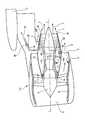
図1、2および3の各々により示されているバイパス・タービン・エンジンは、長手方向軸L−Lを有し、前に、空気入口2を、後ろに空気出口3を備えた中空ナセル1からなる。この中空ナセル1は、フェアリング4を内側に保持し、このフェアリング4は、好ましくは、上記のタービン・エンジンの内側ノイズを軽減するのを意図した音響軽減被覆(コーティング)5で少なくとも部分的に被覆されるのが好ましい。The figures of the attached drawings will make it easier to understand how the invention can be implemented. In these drawings, the same reference numerals indicate the same elements.
The bypass turbine engine shown by each of FIGS. 1, 2 and 3 has a longitudinal axis LL, from a hollow nacelle 1 with an
上記の中空ナセル1の内側には、
− 既知の方法で、低圧圧縮器、高圧圧縮器、燃焼室、低圧タービンおよび高圧タービンとからなり、上記のタービン・エンジンの軸方向の熱気流7を発生させる中央熱気流発生器6と、
− 上記の中央熱気流発生器6の軸方向前方に位置し、上記タービン・エンジンの環状冷気流を発生するファン8と、
− 上記の中央発生器6を囲み、それ自体とこの発生器のケーシング11との間に、この発生器を囲む、横断面環状の中間室12を形成する内側フェアリング10が位置し、この内側フェアリングの後部分10Rが上記の熱気流7用の噴射管16の外壁を形成する。Inside the hollow nacelle 1 is
A central hot-
A
An
上記の内側フェアリング10と、これの外側のフェアリング4とは、それらの間に、上記の中央発生器6を囲む、横断面環状のファン・ダクト13を形成し、これを冷気流9が通過する。 The
内側フェアリング10と中央発生器6との間では、その前に、環状空気入口スロット14 が、その後ろには、環状空気排出スロット15が形成されている。こうして、中間室12の前スロット14の所で、冷気流9から流出した冷気流fが吹き抜け、その後、スロット15の所で、上記の熱気流7と上記の冷気流9との境界で排出され、この冷気流fが中央発生器6の温度を調節するのに使用される。 Between the
更にまた、通常の方法で、ナセル1は、サスペンション・パイロン18を介して(一部が描写されている)航空機の翼17により支持されている。 Furthermore, in a conventional manner, the nacelle 1 is supported by an aircraft wing 17 (partially depicted) via a
図1に示されている既知のタービン・エンジンには、予冷却器19が設けられており、これは冷気流9内のファン・ダクト13の上方部に位置する。この予冷器9には、その上に熱気制御弁22が在るダクト21を介して中央発生器6からの、熱気流20が供給される。上記の予冷却器19により発生された、冷却された熱気23は、上記のサスペンション・パイロン18を貫通し、調整弁25が装着されているダクト24を介して使用者装置(図示略)に送られる。 The known turbine engine shown in FIG. 1 is provided with a
よって、既知のレイアウトでは、冷気流の幾らかは予冷却器19から流出して熱気流20を冷却し、冷却された熱気流23を発生し、この結果上記予冷却器は、上記の冷気流の流出部分に対応する加熱された冷気流(図示略)を形成する。この加熱された冷気流は図1には図示されていない、いずれかの既知の方法で外側に排出されて、一般に抗力を増加させる。 Thus, in the known layout, some of the cold airflow will flow out of the
よって、ファン・ダクト13内の予冷却器19の存在と、冷気流9のいくらかの流出と、加熱された冷気の排出とが、図1に示された既知のエンジンの性能を阻害することが容易に理解される。 Thus, the presence of the
図2に描写されている本発明によるナセル1.1には、図1に関し記載されている部材2から18および20から25の全てが見られる。このナセル1.1では、予冷却器19が除去され、予冷却器30と換わっている。この予冷却器30は、熱気流20を供給するダクト21に連結されている入口31と、冷却された熱気23を運ぶダクト24に連結されている出口32とを有する。 In the nacelle 1.1 according to the invention depicted in FIG. 2, all of the
上記の予冷却器30は環状横断面を有し、上記の中間室12と同じ側で内側フェアリング10の後部分10Rの内側に位置し、この後部分の内周全体に亘って延びている。この予冷却器30は軸L−Lと同軸で、上記の後部分10Rと熱接触する。この後部分10Rがファン・ダクト13から出てくる冷気流9と接触するので、上記の予冷却器30は、それ自体、空気のいくらかを流出させる必要も、冷却された熱気を排出させる必要も全く無く、冷気流9により冷却される。 The
図2の全ての要素を示す図3は、更に、本発明によるナセル1.2にバイパス・ダクト33の存在を示す。このバイパス・ダクト33は上記の予冷却器30と平行に取り付けられており、その入口31とその出口32とを連結し、バルブ34が設けられている。よって、必要なら、熱気は、上記の予冷却器30をバイパス(迂回)して、入口31から出口32まで直接通らせることもできる。 FIG. 3, which shows all the elements of FIG. 2, further shows the presence of a
図4から図10までに示されている予冷却器30の実施例は、内側フェアリング10の上記の後部分10Rに構造上組み込まれる。 The embodiment of the
図4から図6までに見られるように、上記の後部分10Rは内壁35と外壁36とからなり、これらは平行で、環状間隙の形態の空間37により相互から離れている。この空間には、上記の内壁35と外壁36とに固定され、空間37を細分する曲がったダクト40を形成する枠38(図5)あるいは枠39(図5)とが位置する。これらのダクト40はナセルの軸L−Lに対し横断方向であり、上記の後部分10Rに沿って分布されている。 As can be seen in FIGS. 4 to 6, the
更にまた、上記の予冷却器30は、(図7参照)
− 熱気入口31に連結され、後部分10R全体に沿ってこれに対し横断方向に上記の空間37(よって、ダクト40内に)上記の熱気(矢印42参照)を分配できる分配管41と、
− 冷却された熱気の出口32に連結され、上記の後部分10Rに沿い、上記のダクト40を通って上記の空間37を通過する上記の空気(矢印44参照)を集めることのできる収集管43とからなる。Furthermore, the
A
A
図7から図10に示されているように、上記の管41と43との横断面は前から後方に減少し、これらの管にそれぞれ設けられている分配オリフィス45と収集オリフィス46についてはその逆である。 As shown in FIGS. 7 to 10, the cross sections of the
1…中空ナセル、2…空気入口、3…空気出口、4…外側フェアリング、6…中央熱気流発生器、8…ファン、9…冷気流、10…内側フェアリング(10R…内側フェアリングの後部分)、12…中間室、13…ファン・ダクト、20…熱気流、30…予冷却器、31…熱気流用入口、32…熱気流用出口、33…バイパス・ダクト、34…バルブ、35…環状間隙空間の内壁、36…環状間隙空間の外壁、37…環状間隙空間、38・39…内側フェアリング後部分補強する枠、40…ダクト、41…分配管、43…収集管、L−L…長手方向軸。 DESCRIPTION OF SYMBOLS 1 ... Hollow nacelle, 2 ... Air inlet, 3 ... Air outlet, 4 ... Outer fairing, 6 ... Central hot air generator, 8 ... Fan, 9 ... Cold air flow, 10 ... Inner fairing (10R ... Inside fairing Rear part), 12 ... Intermediate chamber, 13 ... Fan duct, 20 ... Hot air, 30 ... Precooler, 31 ... Hot air inlet, 32 ... Hot air outlet, 33 ... Bypass duct, 34 ... Valve, 35 ... An inner wall of the annular gap space, 36 ... an outer wall of the annular gap space, 37 ... an annular gap space, 38, 39 ... a frame for reinforcing the rear part of the inner fairing, 40 ... a duct, 41 ... a distribution pipe, 43 ... a collection pipe, LL ... longitudinal axis.
Claims (9)
Translated fromJapanese− このナセル(1)の軸方向に位置する中央熱気流発生器(6)と、
− 上記の中央発生器(6)の前方、上記のナセル(1)内に軸方向に位置し、バイパス・タービン・エンジン用の冷気流(9)を発生させるファン(8)と、
− 上記のナセル(1)の内側に保持されている外側フェアリング(4)と上記の中央発生器(6)を囲む内側フェアリング(10)とであって、これら内外のフェアリングはそれらの間に上記の冷気流(9)用の、横断面環状のファン・ダクト(13)を形成するものと、
− 上記の中央発生器(6)から流出する熱気流(20)用の入口と、上記の冷気流(9)を用いて冷却された熱気流用の出口とを備えた予冷却器(30)とからなり、
上記の予冷却器(30)が、上記の長手方向軸(L−L)を中心に上記の内側フェアリング(10)の後部分(10R)の少なくとも一部の内側に位置し、内側フェアリング(10)の上記の後部分(10R)と熱接触して、内側フェアリング(10)の後部分(10R)上に流出した上記の冷気流(9)により冷却されることを特徴とする航空機用のバイパス・タービン・エンジン。A hollow nacelle (1) having a longitudinal axis (LL) and having an air inlet (2) in front and an air outlet (3) after;
A central hot air generator (6) located in the axial direction of this nacelle (1);
A fan (8) located axially in the nacelle (1) in front of the central generator (6) and generating a cold air flow (9) for abypass turbine engine;
-An outer fairing (4) held inside the nacelle (1) and an inner fairing (10) surrounding the central generator (6), these inner and outer fairings being Forming a fan duct (13) with a circular cross section for the cold airflow (9) between,
A precooler (30) comprising an inlet for the hot air stream (20) flowing out from the central generator (6) and an outlet for the hot air stream cooled using the cold air stream (9); Consists of
The precooler (30) is located inside at least a part of the rear part (10R) of the inner fairing (10) around the longitudinal axis (LL), and the inner fairing An aircraft characterized by being in thermal contact with the rear part (10R) of (10) and being cooled by the cold air flow (9) that has flowed out onto the rear part (10R) of the inner fairing (10) Bypass turbine engine.
− 熱気流(20)用入口(31)に連結され、上記の環状空間(37)の全長に上記の熱気流を分配できる分配管(41)と、
− 冷却された熱気流(23)用出口(32)に連結され、上記の環状空間(37)の全長に亘って、冷却された熱気流を集めることのできる収集管(43)と
からなることを特徴とする請求項4に記載のタービン・エンジン。The precooler (30) is connected to the inlet (31) for the hot air flow (20), and a distribution pipe (41) capable of distributing the hot air flow overthe entire length of the annular space (37),
- connected to the outlet for cooled hot air stream (23) (32), consisting of over theentire lengthof the annular space (37), the collection tube can collect cooled hot air stream (43) The turbine engine according to claim 4.
Applications Claiming Priority (3)
| Application Number | Priority Date | Filing Date | Title |
|---|---|---|---|
| FR0600472 | 2006-01-19 | ||
| FR0600472AFR2896275B1 (en) | 2006-01-19 | 2006-01-19 | DOUBLE FLOW TURBOMOTEUR PROVIDED WITH A PRECOLFER. |
| PCT/FR2007/000090WO2007083026A1 (en) | 2006-01-19 | 2007-01-18 | Dual flow turbine engine equipped with a precooler |
Publications (2)
| Publication Number | Publication Date |
|---|---|
| JP2009523946A JP2009523946A (en) | 2009-06-25 |
| JP4972652B2true JP4972652B2 (en) | 2012-07-11 |
Family
ID=37106239
Family Applications (1)
| Application Number | Title | Priority Date | Filing Date |
|---|---|---|---|
| JP2008550799AActiveJP4972652B2 (en) | 2006-01-19 | 2007-01-18 | Two laminar flow turbine engine with precooler |
Country Status (9)
| Country | Link |
|---|---|
| US (1) | US8141337B2 (en) |
| EP (1) | EP1973778B1 (en) |
| JP (1) | JP4972652B2 (en) |
| CN (1) | CN101374722B (en) |
| BR (1) | BRPI0706872A2 (en) |
| CA (1) | CA2631849C (en) |
| FR (1) | FR2896275B1 (en) |
| RU (1) | RU2411389C2 (en) |
| WO (1) | WO2007083026A1 (en) |
Families Citing this family (22)
| Publication number | Priority date | Publication date | Assignee | Title |
|---|---|---|---|---|
| US8826641B2 (en)* | 2008-01-28 | 2014-09-09 | United Technologies Corporation | Thermal management system integrated pylon |
| US8757960B2 (en) | 2010-12-21 | 2014-06-24 | Hamilton Sundstrand Corporation | Shaft support for air cycle machine |
| US9410482B2 (en)* | 2010-12-24 | 2016-08-09 | Rolls-Royce North American Technologies, Inc. | Gas turbine engine heat exchanger |
| US9062604B2 (en) | 2011-01-14 | 2015-06-23 | Hamilton Sundstrand Corporation | Low pressure bleed architecture |
| US9670842B2 (en) | 2011-01-14 | 2017-06-06 | Hamilton Sundstrand Corporation | Bleed valve module with position feedback and cooling shroud |
| US8661833B2 (en) | 2011-01-14 | 2014-03-04 | Hamilton Sundstrand Corporation | Bleed valve module |
| EP3385510B1 (en) | 2011-03-17 | 2022-02-09 | Airbus Canada Limited Partnership | Control method for operating a precooler in an aircraft and aircraft engine |
| US10634051B2 (en) | 2012-01-09 | 2020-04-28 | United Technologies Corporation | Geared turbofan engine with low pressure environmental control system for aircraft |
| US10093424B2 (en)* | 2014-07-07 | 2018-10-09 | United Technologies Corporation | Low pressure environmental control system with safe pylon transit |
| CN103216361B (en)* | 2013-04-18 | 2015-10-21 | 李宇霞 | Novel small-size duct turbofan engine |
| CN103835836B (en)* | 2014-03-10 | 2015-09-09 | 金剑 | The gas turbine that a kind of bypass ratio is controlled |
| US10487690B2 (en)* | 2014-08-18 | 2019-11-26 | Rohr, Inc. | Actively controlled cooling air exhaust door on an aircraft engine nacelle |
| CN106285949B (en)* | 2015-06-04 | 2018-09-11 | 中国航发商用航空发动机有限责任公司 | Engine high pressure blower outlet cooling system |
| RU2617026C1 (en)* | 2015-12-09 | 2017-04-19 | Владимир Леонидович Письменный | Double-flow jet turbine engine cooling method |
| US10934938B2 (en)* | 2016-07-22 | 2021-03-02 | Raytheon Technologies Corporation | Boundary layer cooling air for embedded engine |
| FR3070967B1 (en)* | 2017-09-14 | 2019-08-30 | Airbus Operations | COMPACT THERMAL EXCHANGE DEVICE INCORPORATED IN AN AIRCRAFT MAT |
| RU2696884C2 (en)* | 2018-01-11 | 2019-08-07 | Акционерное Общество "Государственное Машиностроительное Конструкторское Бюро "Радуга" Имени А.Я. Березняка" | Supersonic straight-flow air-jet engine (versions) |
| RU2679337C1 (en)* | 2018-01-11 | 2019-02-07 | Акционерное Общество "Государственное Машиностроительное Конструкторское Бюро "Радуга" Имени А.Я. Березняка" | Supersonic ramjet engine traction and economic characteristics increasing method (options) |
| RU2701034C1 (en)* | 2019-02-15 | 2019-09-24 | Владимир Леонидович Письменный | Double-flow jet turbine engine |
| RU2704435C1 (en)* | 2019-02-28 | 2019-10-29 | Владимир Леонидович Письменный | Double-circuit gas turbine unit |
| US11274602B2 (en) | 2019-05-24 | 2022-03-15 | Pratt & Whitney Canada Corp. | Air cooler for gas turbine engine |
| US11713719B2 (en)* | 2020-05-07 | 2023-08-01 | The Boeing Company | Engine bleed power recovery systems and related methods |
Family Cites Families (10)
| Publication number | Priority date | Publication date | Assignee | Title |
|---|---|---|---|---|
| GB716145A (en)* | 1952-02-19 | 1954-09-29 | Ernest Lagelbauer | Improvements in aircraft jet propulsion engines including a ducted fan |
| US3842597A (en) | 1973-03-16 | 1974-10-22 | Gen Electric | Gas turbine engine with means for reducing the formation and emission of nitrogen oxides |
| DE2400618B2 (en)* | 1974-01-08 | 1976-10-21 | Siemens AG, 1000 Berlin und 8000 München | CHIP |
| US4254618A (en)* | 1977-08-18 | 1981-03-10 | General Electric Company | Cooling air cooler for a gas turbofan engine |
| US4493184A (en)* | 1983-03-07 | 1985-01-15 | United Technologies Corporation | Pressurized nacelle compartment for active clearance controlled gas turbine engines |
| US5269135A (en)* | 1991-10-28 | 1993-12-14 | General Electric Company | Gas turbine engine fan cooled heat exchanger |
| FR2697289B1 (en)* | 1992-10-28 | 1994-12-09 | Snecma | Double-flow turbojet with air heating system on the primary nozzle. |
| DE4315256A1 (en)* | 1993-05-07 | 1994-11-10 | Mtu Muenchen Gmbh | Device for distributing and supplying and removing a coolant to a wall of a turbo, in particular turbo ramjet engine |
| FR2734319B1 (en)* | 1995-05-15 | 1997-07-18 | Aerospatiale | DEVICE FOR TAKING UP AND COOLING HOT AIR AT AN AIRCRAFT ENGINE |
| FR2734320B1 (en)* | 1995-05-15 | 1997-07-18 | Aerospatiale | DEVICE FOR TAKING UP AND COOLING HOT AIR AT AN AIRCRAFT ENGINE |
- 2006
- 2006-01-19FRFR0600472Apatent/FR2896275B1/ennot_activeExpired - Fee Related
- 2007
- 2007-01-18CACA2631849Apatent/CA2631849C/ennot_activeExpired - Fee Related
- 2007-01-18CNCN200780003259XApatent/CN101374722B/ennot_activeExpired - Fee Related
- 2007-01-18WOPCT/FR2007/000090patent/WO2007083026A1/enactiveApplication Filing
- 2007-01-18JPJP2008550799Apatent/JP4972652B2/enactiveActive
- 2007-01-18RURU2008133990/06Apatent/RU2411389C2/ennot_activeIP Right Cessation
- 2007-01-18BRBRPI0706872-7Apatent/BRPI0706872A2/ennot_activeIP Right Cessation
- 2007-01-18USUS12/160,181patent/US8141337B2/enactiveActive
- 2007-01-18EPEP07717980.2Apatent/EP1973778B1/enactiveActive
Also Published As
| Publication number | Publication date |
|---|---|
| EP1973778A1 (en) | 2008-10-01 |
| EP1973778B1 (en) | 2015-10-14 |
| JP2009523946A (en) | 2009-06-25 |
| RU2411389C2 (en) | 2011-02-10 |
| FR2896275B1 (en) | 2010-05-28 |
| CN101374722A (en) | 2009-02-25 |
| US8141337B2 (en) | 2012-03-27 |
| FR2896275A1 (en) | 2007-07-20 |
| WO2007083026A1 (en) | 2007-07-26 |
| CA2631849C (en) | 2013-10-15 |
| BRPI0706872A2 (en) | 2011-04-12 |
| RU2008133990A (en) | 2010-02-27 |
| CA2631849A1 (en) | 2007-07-26 |
| CN101374722B (en) | 2011-07-06 |
| US20090000305A1 (en) | 2009-01-01 |
Similar Documents
| Publication | Publication Date | Title |
|---|---|---|
| JP4972652B2 (en) | Two laminar flow turbine engine with precooler | |
| JP5139326B2 (en) | Two laminar flow turbine engine with precooler | |
| JP4805352B2 (en) | Turbo fan with precooler | |
| JP5307451B2 (en) | Method and apparatus for mixing fluids in a turbine engine | |
| CA2831313C (en) | Air cooled air cooler for gas turbine engine air system | |
| EP2129579B1 (en) | Air intake duct with thermal anti-icing system | |
| US8029238B2 (en) | System for cooling a downstream cavity of a centrifugal compressor impeller | |
| JP2012504724A (en) | Turbine cooling system | |
| JP2010196699A (en) | Turboprop propulsion device equipped with pusher propeller | |
| US20160290237A1 (en) | Air cooler system for gas turbine engines | |
| JP2016518546A (en) | Device for deicing a separator nose of an aircraft turbine engine | |
| Nesterenko et al. | Improvement of the design and methods of designing tubular air-to-air heat exchangers cooling systems of gas turbines | |
| US20150308340A1 (en) | Aircraft | |
| US11655762B2 (en) | Gas turbine engine with trailing edge heat exchanger | |
| CN215860346U (en) | Integrated structure device of active clearance control system of low-pressure turbine of aircraft engine | |
| CN115419507B (en) | Ventilation air intake system for turbofan engine core compartment |
Legal Events
| Date | Code | Title | Description |
|---|---|---|---|
| A621 | Written request for application examination | Free format text:JAPANESE INTERMEDIATE CODE: A621 Effective date:20091218 | |
| A131 | Notification of reasons for refusal | Free format text:JAPANESE INTERMEDIATE CODE: A131 Effective date:20110816 | |
| A521 | Request for written amendment filed | Free format text:JAPANESE INTERMEDIATE CODE: A523 Effective date:20110926 | |
| TRDD | Decision of grant or rejection written | ||
| A01 | Written decision to grant a patent or to grant a registration (utility model) | Free format text:JAPANESE INTERMEDIATE CODE: A01 Effective date:20120403 | |
| A01 | Written decision to grant a patent or to grant a registration (utility model) | Free format text:JAPANESE INTERMEDIATE CODE: A01 | |
| A61 | First payment of annual fees (during grant procedure) | Free format text:JAPANESE INTERMEDIATE CODE: A61 Effective date:20120409 | |
| FPAY | Renewal fee payment (event date is renewal date of database) | Free format text:PAYMENT UNTIL: 20150413 Year of fee payment:3 | |
| R150 | Certificate of patent or registration of utility model | Free format text:JAPANESE INTERMEDIATE CODE: R150 Ref document number:4972652 Country of ref document:JP Free format text:JAPANESE INTERMEDIATE CODE: R150 | |
| FPAY | Renewal fee payment (event date is renewal date of database) | Free format text:PAYMENT UNTIL: 20150413 Year of fee payment:3 | |
| S111 | Request for change of ownership or part of ownership | Free format text:JAPANESE INTERMEDIATE CODE: R313111 | |
| S631 | Written request for registration of reclamation of domicile | Free format text:JAPANESE INTERMEDIATE CODE: R313631 | |
| S633 | Written request for registration of reclamation of name | Free format text:JAPANESE INTERMEDIATE CODE: R313633 | |
| FPAY | Renewal fee payment (event date is renewal date of database) | Free format text:PAYMENT UNTIL: 20150413 Year of fee payment:3 | |
| R350 | Written notification of registration of transfer | Free format text:JAPANESE INTERMEDIATE CODE: R350 | |
| R250 | Receipt of annual fees | Free format text:JAPANESE INTERMEDIATE CODE: R250 | |
| R250 | Receipt of annual fees | Free format text:JAPANESE INTERMEDIATE CODE: R250 | |
| R250 | Receipt of annual fees | Free format text:JAPANESE INTERMEDIATE CODE: R250 | |
| R250 | Receipt of annual fees | Free format text:JAPANESE INTERMEDIATE CODE: R250 | |
| R250 | Receipt of annual fees | Free format text:JAPANESE INTERMEDIATE CODE: R250 | |
| R250 | Receipt of annual fees | Free format text:JAPANESE INTERMEDIATE CODE: R250 |