JP4972417B2 - Member joining method and structure - Google Patents
Member joining method and structureDownload PDFInfo
- Publication number
- JP4972417B2 JP4972417B2JP2007016943AJP2007016943AJP4972417B2JP 4972417 B2JP4972417 B2JP 4972417B2JP 2007016943 AJP2007016943 AJP 2007016943AJP 2007016943 AJP2007016943 AJP 2007016943AJP 4972417 B2JP4972417 B2JP 4972417B2
- Authority
- JP
- Japan
- Prior art keywords
- end portion
- main member
- main
- auxiliary
- auxiliary member
- Prior art date
- Legal status (The legal status is an assumption and is not a legal conclusion. Google has not performed a legal analysis and makes no representation as to the accuracy of the status listed.)
- Active
Links
- 238000005304joiningMethods0.000titleclaimsdescription48
- 238000000034methodMethods0.000titleclaimsdescription26
- 238000003466weldingMethods0.000claimsdescription27
- 239000000463materialSubstances0.000claimsdescription16
- 238000010276constructionMethods0.000description8
- 229910000838Al alloyInorganic materials0.000description7
- 238000010586diagramMethods0.000description7
- 229910000831SteelInorganic materials0.000description4
- 238000003825pressingMethods0.000description4
- 239000010959steelSubstances0.000description4
- 230000000994depressogenic effectEffects0.000description2
- 238000003756stirringMethods0.000description2
- 230000000694effectsEffects0.000description1
- 238000003754machiningMethods0.000description1
- 238000004519manufacturing processMethods0.000description1
- 238000002844meltingMethods0.000description1
- 230000008018meltingEffects0.000description1
- 230000003014reinforcing effectEffects0.000description1
- 239000000126substanceSubstances0.000description1
Images


Classifications
- B—PERFORMING OPERATIONS; TRANSPORTING
- B23—MACHINE TOOLS; METAL-WORKING NOT OTHERWISE PROVIDED FOR
- B23K—SOLDERING OR UNSOLDERING; WELDING; CLADDING OR PLATING BY SOLDERING OR WELDING; CUTTING BY APPLYING HEAT LOCALLY, e.g. FLAME CUTTING; WORKING BY LASER BEAM
- B23K20/00—Non-electric welding by applying impact or other pressure, with or without the application of heat, e.g. cladding or plating
- B23K20/12—Non-electric welding by applying impact or other pressure, with or without the application of heat, e.g. cladding or plating the heat being generated by friction; Friction welding
- B23K20/122—Non-electric welding by applying impact or other pressure, with or without the application of heat, e.g. cladding or plating the heat being generated by friction; Friction welding using a non-consumable tool, e.g. friction stir welding
- B23K20/1265—Non-butt welded joints, e.g. overlap-joints, T-joints or spot welds
- B—PERFORMING OPERATIONS; TRANSPORTING
- B21—MECHANICAL METAL-WORKING WITHOUT ESSENTIALLY REMOVING MATERIAL; PUNCHING METAL
- B21J—FORGING; HAMMERING; PRESSING METAL; RIVETING; FORGE FURNACES
- B21J5/00—Methods for forging, hammering, or pressing; Special equipment or accessories therefor
- B21J5/06—Methods for forging, hammering, or pressing; Special equipment or accessories therefor for performing particular operations
- B21J5/063—Friction heat forging
- B—PERFORMING OPERATIONS; TRANSPORTING
- B23—MACHINE TOOLS; METAL-WORKING NOT OTHERWISE PROVIDED FOR
- B23K—SOLDERING OR UNSOLDERING; WELDING; CLADDING OR PLATING BY SOLDERING OR WELDING; CUTTING BY APPLYING HEAT LOCALLY, e.g. FLAME CUTTING; WORKING BY LASER BEAM
- B23K20/00—Non-electric welding by applying impact or other pressure, with or without the application of heat, e.g. cladding or plating
- B23K20/12—Non-electric welding by applying impact or other pressure, with or without the application of heat, e.g. cladding or plating the heat being generated by friction; Friction welding
- B23K20/122—Non-electric welding by applying impact or other pressure, with or without the application of heat, e.g. cladding or plating the heat being generated by friction; Friction welding using a non-consumable tool, e.g. friction stir welding
- B23K20/1245—Non-electric welding by applying impact or other pressure, with or without the application of heat, e.g. cladding or plating the heat being generated by friction; Friction welding using a non-consumable tool, e.g. friction stir welding characterised by the apparatus
- B23K20/125—Rotary tool drive mechanism
- B—PERFORMING OPERATIONS; TRANSPORTING
- B23—MACHINE TOOLS; METAL-WORKING NOT OTHERWISE PROVIDED FOR
- B23K—SOLDERING OR UNSOLDERING; WELDING; CLADDING OR PLATING BY SOLDERING OR WELDING; CUTTING BY APPLYING HEAT LOCALLY, e.g. FLAME CUTTING; WORKING BY LASER BEAM
- B23K20/00—Non-electric welding by applying impact or other pressure, with or without the application of heat, e.g. cladding or plating
- B23K20/12—Non-electric welding by applying impact or other pressure, with or without the application of heat, e.g. cladding or plating the heat being generated by friction; Friction welding
- B23K20/122—Non-electric welding by applying impact or other pressure, with or without the application of heat, e.g. cladding or plating the heat being generated by friction; Friction welding using a non-consumable tool, e.g. friction stir welding
- B23K20/1245—Non-electric welding by applying impact or other pressure, with or without the application of heat, e.g. cladding or plating the heat being generated by friction; Friction welding using a non-consumable tool, e.g. friction stir welding characterised by the apparatus
- B23K20/126—Workpiece support, i.e. backing or clamping
- B—PERFORMING OPERATIONS; TRANSPORTING
- B23—MACHINE TOOLS; METAL-WORKING NOT OTHERWISE PROVIDED FOR
- B23K—SOLDERING OR UNSOLDERING; WELDING; CLADDING OR PLATING BY SOLDERING OR WELDING; CUTTING BY APPLYING HEAT LOCALLY, e.g. FLAME CUTTING; WORKING BY LASER BEAM
- B23K2101/00—Articles made by soldering, welding or cutting
- B23K2101/04—Tubular or hollow articles
- B23K2101/045—Hollow panels
- B—PERFORMING OPERATIONS; TRANSPORTING
- B23—MACHINE TOOLS; METAL-WORKING NOT OTHERWISE PROVIDED FOR
- B23K—SOLDERING OR UNSOLDERING; WELDING; CLADDING OR PLATING BY SOLDERING OR WELDING; CUTTING BY APPLYING HEAT LOCALLY, e.g. FLAME CUTTING; WORKING BY LASER BEAM
- B23K2103/00—Materials to be soldered, welded or cut
- B23K2103/08—Non-ferrous metals or alloys
- B23K2103/10—Aluminium or alloys thereof
- B—PERFORMING OPERATIONS; TRANSPORTING
- B23—MACHINE TOOLS; METAL-WORKING NOT OTHERWISE PROVIDED FOR
- B23K—SOLDERING OR UNSOLDERING; WELDING; CLADDING OR PLATING BY SOLDERING OR WELDING; CUTTING BY APPLYING HEAT LOCALLY, e.g. FLAME CUTTING; WORKING BY LASER BEAM
- B23K2103/00—Materials to be soldered, welded or cut
- B23K2103/18—Dissimilar materials
- B23K2103/20—Ferrous alloys and aluminium or alloys thereof
- Y—GENERAL TAGGING OF NEW TECHNOLOGICAL DEVELOPMENTS; GENERAL TAGGING OF CROSS-SECTIONAL TECHNOLOGIES SPANNING OVER SEVERAL SECTIONS OF THE IPC; TECHNICAL SUBJECTS COVERED BY FORMER USPC CROSS-REFERENCE ART COLLECTIONS [XRACs] AND DIGESTS
- Y10—TECHNICAL SUBJECTS COVERED BY FORMER USPC
- Y10T—TECHNICAL SUBJECTS COVERED BY FORMER US CLASSIFICATION
- Y10T428/00—Stock material or miscellaneous articles
- Y10T428/12—All metal or with adjacent metals
Landscapes
- Engineering & Computer Science (AREA)
- Mechanical Engineering (AREA)
- Pressure Welding/Diffusion-Bonding (AREA)
Description
Translated fromJapanese本発明は部材接合方法及び構造に関するものである。 The present invention relates to a member joining method and structure.
接合すべき部材を溶融させずに相互に接続する方法として摩擦撹拌接合がある(例えば、特許文献1参照)。 Friction stir welding is a method for connecting members to be joined together without melting them (see, for example, Patent Document 1).
この技法では、被接合部材を重ね合わせた被接合物を、裏当て部材である支持ツールに載せたうえ、被接合物に接合ツールを回転させながら押し付け、摩擦熱と塑性流動により軟化した材料を撹拌して同化させる。 In this technique, the object to be joined is placed on a support tool that is a backing member, and the material that has been softened by frictional heat and plastic flow is pressed against the object while rotating the joining tool. Agitate to assimilate.
次いで、接合ツールを被接合物から離して材料が同化した部位を硬化させ、被接合部材を相互に接合する。 Next, the part to which the material is assimilated is cured by separating the joining tool from the object to be joined, and the members to be joined are joined to each other.
接合ツールは、円柱状のショルダ部と、当該ショルダ部に同軸に連なり且つツール先端へ向けて突出する短円筒状でショルダ部よりも外径が小さいピン部とを備えている。 The joining tool includes a columnar shoulder portion and a pin portion that is coaxial with the shoulder portion and projects toward the tip of the tool and has a smaller outer diameter than the shoulder portion.
また、アルミニウム合金を素材とした中空押し出し形材を二つ並べたうえ、この形材を摩擦撹拌接合によって一体化して構造体を製作する手法も既に提案されている(例えば、特許文献2参照)。
二つの面板の間をリブによって接続した断面を呈する形材は、面板とリブの共同によりこれら単体を上回る剛性を発揮するが、時として形材の剛性を局所的に強めることが要求される。 A shape member having a cross section in which two face plates are connected by ribs exhibits rigidity exceeding that of the simple substance due to the joint of the face plate and the ribs, but sometimes it is required to locally increase the rigidity of the shape member.
この場合、二つの面板の間にリブを追加するという手立てが考えられるが、リブは形材の全長にわたって存在するため、結果的に形材の重量が増えてしまうし、コストアップにもなる。 In this case, it is conceivable to add a rib between the two face plates. However, since the rib exists over the entire length of the shape member, as a result, the weight of the shape member increases and the cost increases.
本発明は上述した実情に鑑みてなしたもので、形材の補強に適した部材接合方法及び構造を提供することを目的としている。 The present invention has been made in view of the above-described circumstances, and an object thereof is to provide a member joining method and structure suitable for reinforcing a shape member.
上記目的を達成するため、請求項1に記載の発明では、主部材の第1の個所とそれに向き合う第2の個所のそれぞれに孔を正対するように穿設し、これらの孔に補助部材を、その先端部分が主部材の第2の個所の孔に入り且つ基端部分が主部材の第1の個所の孔に入るように差し込み、接合ツールを回転させながら補助部材の先端に押し付け、摩擦熱と塑性流動により軟化した補助部材の材料で主部材の第2の個所を部材厚み方向に挟み、この後、接合ツールを主部材から引き離して、補助部材の塑性流動部位を硬化させ、更にまた、接合ツールを回転させながら補助部材の基端に押し付け、摩擦熱と塑性流動により軟化した補助部材の材料で主部材の第1の個所を部材厚み方向に挟み、この後、接合ツールを主部材から引き離して、補助部材の塑性流動部位を硬化させる。 In order to achieve the above object, in the first aspect of the present invention, the first member of the main member and the second member facing the second member are respectively provided with holes facing each other, and auxiliary members are provided in these holes. , Insert the tip part into the hole in the second part of the main member and the base part into the hole in the first part of the main member, press against the tip of the auxiliary member while rotating the welding tool, and friction The auxiliary member material softened by heat and plastic flow is used to sandwich the second part of the main member in the thickness direction of the main member, and then the welding tool is pulled away from the main member to cure the plastic flow site of the auxiliary member. , While rotating the welding tool, press against the base end of the auxiliary member, sandwich the first part of the main member in the member thickness direction with the material of the auxiliary member softened by frictional heat and plastic flow, and then the welding tool Pull away from the auxiliary part Curing the plastic flow portion.
請求項2に記載の発明では、第1の個所と第2の個所のそれぞれに正対する孔が穿設してある主部材と、先端部分が主部材の第2の個所の孔に入り且つ基端部分が主部材の第1の個所の孔に入った補助部材とを備え、この補助部材の先端部分及び基端部分の双方を、摩擦熱と塑性流動により前記主部材の第1、第2の個所を部材厚み方向に挟むように形作った構成を採る。 In the second aspect of the present invention, the main member in which holes facing each of the first part and the second part are formed, and the tip part enters the hole in the second part of the main member and An auxiliary member having an end portion in a hole in the first portion of the main member, and both the distal end portion and the proximal end portion of the auxiliary member are connected to the first and second portions of the main member by frictional heat and plastic flow. A configuration is adopted in which the portion is sandwiched in the thickness direction of the member.
請求項3に記載の発明では、第1の個所と第2の個所のそれぞれに正対する孔が穿設してある主部材と、先端部分が主部材の第2の個所の孔に入り且つ基端部分が主部材の第1の個所の孔に入った補助部材と、第1の個所に係合し得るように補助部材の基端部分に設けたフランジとを備え、前記補助部材の先端部分及び基端部分の双方を、摩擦熱と塑性流動により前記主部材の第1、第2の個所を部材厚み方向に挟むように形作った構成を採る。 In the invention according to
請求項4に記載の発明では、第1の個所と第2の個所のそれぞれに正対する孔が穿設してある主部材と、先端部分が主部材の第2の個所の孔に入り且つ基端部分が主部材の第1の個所の孔に入った補助部材と、当該補助部材の基端部分、あるいは先端部分のいずれかに外嵌して主部材に当接する付加部材とを備え、前記補助部材の先端部分及び基端部分の双方を、摩擦熱と塑性流動により前記主部材の第1、第2の個所、並びに付加部材を部材厚み方向に挟むように形作った構成を採る。 In the invention according to
請求項5に記載の発明では、第1の個所と第2の個所のそれぞれに正対する孔が穿設してある主部材と、先端部分が主部材の第2の個所の孔に入り且つ基端部分が主部材の第1の個所の孔に入った補助部材と、当該補助部材の基端部分、あるいは先端部分のいずれかに外嵌して主部材に当接する付加部材とを備え、前記補助部材の先端部分及び基端部分の双方を、摩擦熱と塑性流動により前記主部材の第1、第2の個所を部材厚み方向に挟むように形作り、付加部材に同化させた構成を採る。 According to the fifth aspect of the present invention, the main member in which holes facing each of the first part and the second part are formed, and the tip part enters the hole in the second part of the main member and An auxiliary member having an end portion that enters a hole in the first portion of the main member, and an additional member that is externally fitted to either the proximal end portion or the distal end portion of the auxiliary member and contacts the main member, Both the front end portion and the base end portion of the auxiliary member are shaped so as to sandwich the first and second portions of the main member in the member thickness direction by frictional heat and plastic flow, and are made assimilated to the additional member.
請求項6に記載の発明では、第1の個所と第2の個所のそれぞれに正対する孔が穿設してある主部材と、先端部分が主部材の第2の個所の孔に入り且つ基端部分が主部材の第1の個所の孔に入った補助部材と、当該補助部材の基端部分に外嵌して主部材に当接する第1の付加部材と、前記補助部材の先端部分に外嵌して主部材に当接する第2の付加部材とを備え、前記補助部材の先端部分及び基端部分の双方を、摩擦熱と塑性流動により前記主部材の第1、第2の個所、並びに第1、第2の付加部材を部材厚み方向に挟むように形作った構成を採る。 According to the sixth aspect of the present invention, the main member in which the holes facing each of the first place and the second place are formed, and the tip portion enters the hole in the second place of the main member and An auxiliary member having an end portion in a hole in a first location of the main member, a first additional member that is fitted on the base end portion of the auxiliary member and contacts the main member, and a distal end portion of the auxiliary member A second additional member that is externally fitted and abuts against the main member, and both the distal end portion and the proximal end portion of the auxiliary member are first and second portions of the main member by frictional heat and plastic flow, In addition, the first and second additional members are formed so as to be sandwiched in the member thickness direction.
請求項7に記載の発明では、第1の個所と第2の個所のそれぞれに正対する孔が穿設してある主部材と、先端部分が主部材の第2の個所の孔に入り且つ基端部分が主部材の第1の個所の孔に入った補助部材と、当該補助部材の基端部分に外嵌して主部材に当接する第1の付加部材と、前記補助部材の先端部分に外嵌して主部材に当接する第2の付加部材とを備え、前記補助部材の先端部分及び基端部分の双方を、摩擦熱と塑性流動により前記主部材の第1、第2の個所を部材厚み方向に挟むように形作り、第1、第2の付加部材に同化させた構成を採る。 According to the seventh aspect of the present invention, the main member in which a hole facing each of the first portion and the second portion is formed, and the tip portion enters the hole in the second portion of the main member and An auxiliary member having an end portion in a hole in a first location of the main member, a first additional member that is fitted on the base end portion of the auxiliary member and contacts the main member, and a distal end portion of the auxiliary member A second additional member that is externally fitted and abuts against the main member. Both the distal end portion and the proximal end portion of the auxiliary member are connected to the first and second portions of the main member by frictional heat and plastic flow. It is shaped so as to be sandwiched in the thickness direction of the member, and adopts a structure assimilated to the first and second additional members.
本発明の部材接合方法及び構造によれば、下記のような優れた効果を奏し得る。 According to the member joining method and structure of the present invention, the following excellent effects can be obtained.
(1)請求項1〜請求項7に記載の発明のいずれにおいても、摩擦熱と塑性流動により補助部材の基端部分と先端部分を、主部材の第1、第2の個所を部材厚み方向に挟むように形作るので、主部材の剛性が局所的に高まり、しかも主部材の重量増加を抑えることができる。 (1) In any of the first to seventh aspects of the invention, the base end portion and the tip end portion of the auxiliary member are formed by frictional heat and plastic flow, and the first and second portions of the main member are set in the member thickness direction. Therefore, the rigidity of the main member is locally increased and an increase in the weight of the main member can be suppressed.
(2)請求項4〜請求項7に記載の発明のいずれにおいても、主部材の剛性向上と同時に付加部材の取り付けも完了するので、部材組付工程が減ることになる。 (2) In any of the inventions according to
以下、本発明の実施の形態を図面に基づき説明する。 Hereinafter, embodiments of the present invention will be described with reference to the drawings.
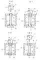
図1は本発明の部材接合構造の第1の例であり、凹部1を有する裏当て部材2と、短円柱状のピン部3を円柱状のショルダ部4の先端面に同軸に連ねた接合ツール5とを用いて、矩形断面の中空形材である主部材6に、丸棒状の補助部材7を接合する。 FIG. 1 shows a first example of a member joining structure according to the present invention, in which a
補助部材7は、アルミニウム合金を素材とし、主部材6と裏当て部材2と接合ツール5は、アルミニウム合金よりも硬く且つ軟化温度が高い鋼を素材としている。 The
主部材6の第1の個所8aとそれに向き合う第2の個所8bのそれぞれに孔9a,9bを穿設し、裏当て部材2の凹部1で補助部材7の基端部分を受け、第1の個所8aの孔9aに補助部材7の基端部分が入り且つ第2の個所8bの孔9bに補助部材7の先端部分が入るように主部材6を配置したうえ、接合ツール5を補助部材7の先端部分に相対させる(図1(a)参照)。
孔9a,9bの形状は、補助部材7が丸棒状であれば、ドリルで穿設した丸孔でよく、補助部材7が角棒状、もしくは板状である場合には、それに見合った形の孔9a,9bを機械加工などで各個所8a,8bに穿設することになる。 The shape of the
接合ツール5を回転させながら、ピン部3を補助部材7の先端に押し付けると、摩擦熱と塑性流動により軟化したこの部位にピン部3が徐々にめり込む。 When the
やがて、接合ツール5のショルダ部4の端面が補助部材7の先端に押し付けられ、摩擦熱と塑性流動により軟化した補助部材7の先端部分に由来する材料が、第2の個所8bの孔9bから主部材6内方側へと押し込まれる(図1(b)参照)。 Eventually, the end surface of the
回転している接合ツール5のピン部3を丸棒状の補助部材7の先端部分に押し付けると、初めのうちは補助部材7も周方向へ回ることがある。 When the
この補助部材7の回動は材料の軟化に伴って収まるが、クランプのような機械的手段を用いて補助部材7の回動を抑えるという手法も採れる。 Although the rotation of the
接合ツール5の押圧力は、補助部材7を介して裏当て部材2に伝わるので、主部材6の第1の個所8aと第2の個所8bの間にある第3の個所8cや第4の個所8dには座屈変形が生じない。 Since the pressing force of the
この後、接合ツール5を補助部材7から引き離して、主部材6の第2の個所8bを孔9bの周囲において部材厚み方向に挟んでいる補助部材7の塑性流動部位を硬化させ、補助部材7の基端部分を裏当て部材2から取り外したうえ、主部材6及び補助部材7を逆向きにし、補助部材7の先端変形部位を裏当て部材(図示せず)により受け、接合ツール5を補助部材7の基端部分に相対させる。 Thereafter, the
接合ツール5を回転させながら、ピン部3を補助部材7の基端に押し付けると、摩擦熱と塑性流動により軟化したこの部位にピン部3が徐々にめり込む。 When the
やがて、接合ツール5のショルダ部4の端面が補助部材7の基端に押し付けられ、摩擦熱と塑性流動により軟化した補助部材7の基端部分に由来する材料が、第1の個所8aの孔9aから主部材6内方側へと押し込まれる(図1(c)参照)。 Eventually, the end surface of the
既に補助部材7の先端部分の塑性流動部位が主部材6の第2の個所8bに密着固化しているため、補助部材7は周方向へ回らない。 Since the plastic flow site at the tip of the
接合ツール5の押圧力は、補助部材7を介して第2の個所8bに伝わるので、主部材6の第1の個所8aと第2の個所8bの間にある第3の個所8cや第4の個所8dには座屈変形が生じない。 Since the pressing force of the
この後、接合ツール5を補助部材7から引き離して、主部材6の第1の個所8aを孔9aの周囲において部材厚み方向に挟んでいる補助部材7の塑性流動部位を硬化させる(図1(d)参照)。 Thereafter, the
すなわち、塑性流動させた補助部材7の先端部分で主部材6の第2の個所8bを挟み、同じく、塑性流動させた補助部材7の基端部分で、主部材6の第1の個所8aを挟むので、主部材6の剛性が局所的に高まることになる。 That is, the
また、接合ツール5のピン部3がめり込んだあとに形作られた補助部材7の先端部分の穴12と基端部分の穴13は、雌ねじ加工を施せば別部材のボルト締結に利用できる。 Further, the
図2は本発明の部材接合構造の第2の例であり、図中、図1と同一の符号を付した部分は同一物を表わしている。 FIG. 2 shows a second example of the member joining structure according to the present invention. In the figure, the same reference numerals as those in FIG. 1 denote the same parts.
この例では、平らな裏当て部材14と、先に述べた接合ツール5とを用いて、矩形断面の中空形材である主部材6に、その第1の個所8aに当接するフランジ15を基端部分に有する丸棒状の補助部材16を接合する。 In this example, by using the
補助部材16は、アルミニウム合金を素材とし、裏当て部材14は、アルミニウム合金よりも硬く且つ軟化温度が高い鋼を素材としている。 The
裏当て部材14で補助部材16のフランジ15を受け、第1の個所8aの孔9aに補助部材16の基端部分が入り且つ第2の個所8bの孔9bに補助部材16の先端部分が入るように主部材6を配置してフランジ15に第1の個所8aを載せ、接合ツール5を補助部材16の先端部分に相対させる(図2(a)参照)。 The
接合ツール5を回転させながら、ピン部3を補助部材16の先端に押し付けると、摩擦熱と塑性流動により軟化したこの部位にピン部3が徐々にめり込む。 When the
やがて、接合ツール5のショルダ部4の端面が補助部材16の先端に押し付けられ、摩擦熱と塑性流動によって軟化した補助部材16の先端部分に由来する材料が、第2の個所8bの孔9bから主部材6内方側へと押し込まれる(図2(b)参照)。 Eventually, the end surface of the
回転している接合ツール5のピン部3を丸棒状の補助部材16の先端部分に押し付けると、初めのうちは補助部材16も周方向へ回ることがある。 When the
この補助部材16の回動は材料の軟化に伴って収まるが、クランプのような機械的手段を用いて補助部材16の回動を抑えるという手法も採れる。 The rotation of the
接合ツール5の押圧力は、補助部材16を介して裏当て部材14に伝わるので、主部材6の第1の個所8aと第2の個所8bの間にある第3の個所8cや第4の個所8dには座屈変形が生じない。 Since the pressing force of the
この後、接合ツール5を補助部材16から引き離して、主部材6の第2の個所8bを孔9bの周囲において部材厚み方向に挟んでいる補助部材16の塑性流動部位を硬化させ、補助部材7の基端部分を裏当て部材2から取り外したうえ、主部材6及び補助部材16を逆向きにし、補助部材16の先端変形部位を裏当て部材(図示せず)により受け、接合ツール5を補助部材16のフランジ15に相対させる。 Thereafter, the joining
接合ツール5を回転させながら、ピン部3を補助部材16の基端に押し付けると、摩擦熱と塑性流動により軟化したこの部位にピン部3が徐々にめり込む。 When the
やがて、接合ツール5のショルダ部4の端面が、補助部材16のフランジ15に押し付けられ、摩擦熱と塑性流動により軟化した補助部材16のフランジ15に由来する材料が、第1の個所8aの孔9aから主部材6内方側へと押し込まれる(図2(c)参照)。 Eventually, the end face of the
既に補助部材16の先端部分の塑性流動部位が主部材6の第2の個所8bに密着固化しているため、補助部材16は周方向へ回らない。 Since the plastic flow region at the tip of the
接合ツール5の押圧力は、補助部材16を介して第2の個所8bに伝わるので、主部材6の第1の個所8aと第2の個所8bの間にある第3の個所8cや第4の個所8dには座屈変形が生じない。 Since the pressing force of the
この後、接合ツール5を補助部材16から引き離して、主部材6の第1の個所8aを孔9aの周囲において部材厚み方向に挟んでいる補助部材16の塑性流動部位を硬化させる(図2(d)参照)。 Thereafter, the joining
すなわち、塑性流動させた補助部材16の先端部分で主部材6の第2の個所8bを挟み、同じく、塑性流動させた補助部材16の基端部分やフランジ15で、主部材6の第1の個所8aを挟むので、主部材6の剛性が局所的に高まることになる。 That is, the
また、接合ツール5のピン部3がめり込んだあとに形作られた補助部材16の先端部分の穴19と基端部分の穴20は、雌ねじ加工を施せば別部材のボルト締結に利用できる。 Further, the
図3は本発明の部材接合構造の第3の例であり、図中、図1と同一の符号を付した部分は同一物を表わしている。 FIG. 3 shows a third example of the member joining structure according to the present invention. In the figure, the same reference numerals as those in FIG. 1 denote the same parts.
この例では、先に説明した図1(b)の工程を経て補助部材7の先端部分側の塑性流動部位が硬化した後、主部材6及び補助部材7を逆向きにし、接合ツール5を補助部材7の基端部分に相対させたうえ、付加部材24を補助部材7に外嵌し且つ主部材6の第1の個所8aに載るように配置する。 In this example, after the plastic flow site on the tip portion side of the
この付加部材24は、鋼を素材としている。 The
接合ツール5を回転させながら、ピン部3を補助部材7の基端に押し付けると、摩擦熱と塑性流動により軟化したこの部位にピン部3が徐々にめり込む。 When the
やがて、接合ツール5のショルダ部4の端面が、補助部材7の基端に押し付けられ、摩擦熱と塑性流動により軟化した補助部材7の基端部分に由来する材料が、第1の個所8aの孔9aから主部材6内方側へと押し込まれる(図3(a)参照)。 Eventually, the end surface of the
この後、接合ツール5を補助部材7から引き離して、当該付加部材24と主部材6の第1の個所8aを孔9aの周囲において部材厚み方向に挟んでいる補助部材7の塑性流動部位を硬化させる(図3(b)参照)。 Thereafter, the joining
すなわち、塑性流動させた補助部材7の先端部分で主部材6の第2の個所8bを挟み、同じく、塑性流動させた補助部材7の基端部分で、付加部材24と主部材6の第1の個所8aを挟むので、主部材6の剛性が局所的に高まり、これと同時に付加部材24の装着も完了するため、部材組付工程が減ることになる。 That is, the
また、接合ツール5のピン部3がめり込んだあとの形作られた補助部材7の先端部分の穴12と基端部分の穴25は、雌ねじ加工を施せば別部材のボルト締結に利用できる。 Further, the
図4は本発明の部材接合構造の第4の例であり、図中、図1と同一の符号を付した部分は同一物を表わしている。 FIG. 4 shows a fourth example of the member joining structure according to the present invention. In the figure, the same reference numerals as those in FIG. 1 denote the same parts.
この例では、先に説明した図1(b)の工程を経て補助部材7の先端部分側の塑性流動部位が硬化した後、主部材6及び補助部材7を逆向きにし、接合ツール5を補助部材7の基端部分に相対させたうえ、付加部材21を補助部材7に外嵌し且つ主部材6の第1の個所8aに載るように配置する。 In this example, after the plastic flow site on the tip portion side of the
この付加部材21は、アルミニウム合金を素材としている。 The
接合ツール5を回転させながら、ピン部3を補助部材7の基端に押し付けると、摩擦熱と塑性流動により軟化したこの部位にピン部3が徐々にめり込む。 When the
やがて、接合ツール5のショルダ部4の端面が、補助部材7の基端と付加部材21に押し付けられ、当該付加部材21も摩擦熱と塑性流動により軟化して、接合ツール5のピン部3の周囲に、付加部材21と補助部材7の基端部分に由来する材料の同化層22が軟化した状態で生じる(図4(a)参照)。 Eventually, the end face of the
この後、接合ツール5を補助部材7、及び付加部材21から引き離して、塑性流動部位である同化層22を硬化させる(図4(b)参照)。 Thereafter, the joining
すなわち、塑性流動させた補助部材7の先端部分で主部材6の第2の個所8bを挟み、同化層22で主部材6の第1の個所8aを挟むので、主部材6の剛性が局所的に高まり、これと同時に付加部材21の装着も完了するため、部材組付工程が減ることになる。 That is, since the
また、接合ツール5のピン部3がめり込んだあとに形作られた補助部材7の先端部分の穴12と基端部分の穴23は、雌ねじ加工を施せば別部材のボルト締結に利用できる。 Further, the
図5は本発明の部材接合構造の第5の例であり、図中、図3と同一の符号を付した部分は同一物を表わしている。 FIG. 5 shows a fifth example of the member joining structure according to the present invention. In the figure, the same reference numerals as those in FIG. 3 denote the same parts.
この例では、主部材6に付加部材24を装着するのとは別に、鋼を素材とする付加部材26を補助部材7の先端部分に外嵌させ、当該付加部材26と主部材6の第2の個所8bを、塑性流動させた補助部材7で挟む。 In this example, in addition to attaching the
よって、主部材6の剛性を局所的に高める際に、付加部材24,26の装着も完了し、部材組付工程が減ることになる。 Therefore, when the rigidity of the
また、接合ツール5のピン部3がめり込んだあとに形作られた補助部材7の先端部分の穴27と基端部分の穴25は、雌ねじ加工を施せば別部材のボルト締結に利用できる。 Further, the
図6は本発明の部材接合構造の第6の例であり、図中、図4と同一の符号を付した部分は同一物を表わしている。 FIG. 6 shows a sixth example of the member joining structure according to the present invention. In the figure, the same reference numerals as those in FIG. 4 denote the same parts.
この例では、主部材6に付加部材21を装着するのとは別に、アルミニウム合金を素材とする付加部材28を補助部材7の先端部分に外嵌させ、主部材6の第2の個所8bを、塑性流動たせた補助部材7と付加部材21の同化層29で挟む。 In this example, apart from mounting the
よって、主部材6の剛性を局所的に高める際に、付加部材21,28の装着も完了し、部材組付工程が減ることになる。 Therefore, when the rigidity of the
また、接合ツール5のピン部3がめり込んだあとに形作られた補助部材7の先端部分の穴30と基端部分の穴23は、雌ねじ加工を施せば別部材のボルト締結に利用できる。 Further, the
図7は本発明の部材接合構造に関連する施工手順の他の例であり、図中、図1と同一の符号を付した部分は同一物を表わしている。 FIG. 7 shows another example of the construction procedure related to the member joining structure of the present invention. In the figure, the parts denoted by the same reference numerals as those in FIG. 1 represent the same items.
この例では、接合ツール5を回転させながら、ピン部3を補助部材7の先端に押し付け、摩擦熱と塑性流動により軟化した補助部材7の材料を変形させつつ、第2の個所8bの孔9bから主部材6内方側へと押し込む工程に並行して、別の接合ツール5を回転させながら、ピン部3を補助部材7の基端に押し付け、摩擦熱と塑性流動により軟化した補助部材7の材料を変形させつつ、第1の個所8aの孔9aから主部材6内方側へと押し込む工程を行うようにし、各接合ツール5を補助部材7から引き離して、主部材6の第2の個所8bを挟む補助部材7の塑性流動部位、及び主部材の第1の個所を挟む補助部材の塑性流動部位を硬化させる。 In this example, while rotating the
これは図1の部材接合構造だけでなく、図2〜図6に示す部材接合構造にも適用できる。 This can be applied not only to the member joining structure of FIG. 1 but also to the member joining structures shown in FIGS.
なお、本発明の部材接合方法及び構造は、上述した実施の形態のみに限定されるものではなく、ピン部がない単なる円柱状の接合ツールを用いるようにすること、その他、本発明の要旨を逸脱しない範囲において変更を加え得ることは勿論である。 In addition, the member joining method and structure of the present invention are not limited to the above-described embodiments, and a simple columnar joining tool having no pin portion is used. Of course, changes can be made without departing from the scope.
本発明の部材接合方法及び構造は、様々な部品の接合組付工程に適用できる。 The member joining method and structure of the present invention can be applied to various parts joining and assembling processes.
6 主部材
7 補助部材
8a 第1の個所
8b 第2の個所
9a 孔
9b 孔
15 フランジ
16 補助部材
21 付加部材(第1の付加部材)
24 付加部材(第1の付加部材)
26 付加部材(第2の付加部材)
28 付加部材(第2の付加部材)6
24 Additional member (first additional member)
26 Additional member (second additional member)
28 Additional member (second additional member)
Claims (7)
Translated fromJapanesePriority Applications (3)
| Application Number | Priority Date | Filing Date | Title |
|---|---|---|---|
| JP2007016943AJP4972417B2 (en) | 2006-12-15 | 2007-01-26 | Member joining method and structure |
| US12/518,142US7954692B2 (en) | 2006-12-15 | 2007-12-14 | Structure and method for joining members of structure via friction stir processing |
| PCT/JP2007/001398WO2008072380A1 (en) | 2006-12-15 | 2007-12-14 | Method and structure for joining members |
Applications Claiming Priority (3)
| Application Number | Priority Date | Filing Date | Title |
|---|---|---|---|
| JP2006339029 | 2006-12-15 | ||
| JP2006339029 | 2006-12-15 | ||
| JP2007016943AJP4972417B2 (en) | 2006-12-15 | 2007-01-26 | Member joining method and structure |
Publications (2)
| Publication Number | Publication Date |
|---|---|
| JP2008168334A JP2008168334A (en) | 2008-07-24 |
| JP4972417B2true JP4972417B2 (en) | 2012-07-11 |
Family
ID=39696917
Family Applications (1)
| Application Number | Title | Priority Date | Filing Date |
|---|---|---|---|
| JP2007016943AActiveJP4972417B2 (en) | 2006-12-15 | 2007-01-26 | Member joining method and structure |
Country Status (2)
| Country | Link |
|---|---|
| US (1) | US7954692B2 (en) |
| JP (1) | JP4972417B2 (en) |
Families Citing this family (17)
| Publication number | Priority date | Publication date | Assignee | Title |
|---|---|---|---|---|
| EP1627567B1 (en) | 2002-12-20 | 2008-08-13 | Stork Pmt B.V. | Method and device for processing a carcass part of slaughtered poultry |
| JP2007245198A (en)* | 2006-03-16 | 2007-09-27 | Hino Motors Ltd | Material joining method |
| JP5094140B2 (en)* | 2006-11-09 | 2012-12-12 | 日野自動車株式会社 | Member joint structure |
| US9764375B2 (en)* | 2012-03-02 | 2017-09-19 | Brigham Young University | Friction bit joining of materials using a friction rivet |
| US12186791B2 (en) | 2013-03-22 | 2025-01-07 | Battelle Memorial Institute | Devices and methods for performing shear-assisted extrusion and extrusion processes |
| US11383280B2 (en) | 2013-03-22 | 2022-07-12 | Battelle Memorial Institute | Devices and methods for performing shear-assisted extrusion, extrusion feedstocks, extrusion processes, and methods for preparing metal sheets |
| US11045851B2 (en) | 2013-03-22 | 2021-06-29 | Battelle Memorial Institute | Method for Forming Hollow Profile Non-Circular Extrusions Using Shear Assisted Processing and Extrusion (ShAPE) |
| US20210379638A1 (en) | 2013-03-22 | 2021-12-09 | Battelle Memorial Institute | Devices and Methods for Performing Shear-Assisted Extrusion and Extrusion Processes |
| US12365027B2 (en) | 2013-03-22 | 2025-07-22 | Battelle Memorial Institute | High speed shear-assisted extrusion |
| US12403516B2 (en) | 2013-03-22 | 2025-09-02 | Battelle Memorial Institute | Shape processes, feedstock materials, conductive materials and/or assemblies |
| US10695811B2 (en) | 2013-03-22 | 2020-06-30 | Battelle Memorial Institute | Functionally graded coatings and claddings |
| US10319171B2 (en)* | 2014-03-28 | 2019-06-11 | Ncr Corporation | Media escape prevention for self-service terminal |
| CN105108311A (en)* | 2015-09-10 | 2015-12-02 | 何峰 | Perforated end face and smooth end face connecting method, and perforated end face and another perforated end face connecting method |
| US10583519B2 (en)* | 2016-08-12 | 2020-03-10 | The Boeing Company | Friction stir welding method and assembly |
| US11305374B2 (en)* | 2016-09-22 | 2022-04-19 | Nemak, S.A.B. De C.V. | Method for the production of a cast engine block for a combustion engine and engine block |
| US11549532B1 (en)* | 2019-09-06 | 2023-01-10 | Battelle Memorial Institute | Assemblies, riveted assemblies, methods for affixing substrates, and methods for mixing materials to form a metallurgical bond |
| WO2023043839A1 (en) | 2021-09-15 | 2023-03-23 | Battelle Memorial Institute | Shear-assisted extrusion assemblies and methods |
Family Cites Families (36)
| Publication number | Priority date | Publication date | Assignee | Title |
|---|---|---|---|---|
| US2214339A (en)* | 1937-11-23 | 1940-09-10 | Curtiss Wright Corp | Method of making hollow ribbed propeller blades |
| US2319468A (en)* | 1941-04-10 | 1943-05-18 | Reliance Steel Prod Co | Bridge floor |
| US2779998A (en)* | 1952-01-30 | 1957-02-05 | Lockheed Aircraft Corp | Method of forming a mechanical and electrical connection |
| US2795039A (en)* | 1954-02-15 | 1957-06-11 | Gen Motors Corp | Method of frictionally welding a tube to a metal object |
| US3477115A (en)* | 1967-03-17 | 1969-11-11 | Caterpillar Tractor Co | Method of fastening parts by friction welding |
| US3848389A (en)* | 1969-12-29 | 1974-11-19 | Textron Inc | Bimetal rivets |
| JPS52123358A (en)* | 1976-04-09 | 1977-10-17 | Shigeru Kimura | Frictional welding method |
| JP2827621B2 (en)* | 1991-10-23 | 1998-11-25 | 三菱電機株式会社 | High current substrate and method of manufacturing the same |
| CN1165403C (en)* | 1996-03-19 | 2004-09-08 | 株式会社日立制作所 | Components for friction welding |
| SE508970C2 (en)* | 1996-03-20 | 1998-11-23 | Volvo Ab | Procedure for attaching a fastener, as well as joints and tools for carrying out the procedure |
| US6267684B1 (en)* | 1997-04-30 | 2001-07-31 | Allfast Fastening Systems, Inc. | Rivets and rivet manufacturing methods |
| JPH11179569A (en)* | 1997-12-19 | 1999-07-06 | Nippon Light Metal Co Ltd | Sandwich panel |
| JP4092794B2 (en)* | 1998-11-02 | 2008-05-28 | 日本軽金属株式会社 | Joining method |
| NL1011908C1 (en)* | 1999-04-27 | 2000-10-30 | Fokker Aerostructures Bv | Friction stir welding. |
| JP4494671B2 (en) | 2001-06-04 | 2010-06-30 | 株式会社日立製作所 | Structure and manufacturing method thereof |
| US20030075584A1 (en)* | 2001-10-04 | 2003-04-24 | Sarik Daniel J. | Method and apparatus for friction stir welding |
| US7516534B2 (en)* | 2001-11-25 | 2009-04-14 | Stresswave, Inc. | Method for attaching a nut element to a metal structure |
| JP3861719B2 (en)* | 2002-03-12 | 2006-12-20 | 株式会社デンソー | Friction stir welding method |
| JP4199952B2 (en)* | 2002-03-15 | 2008-12-24 | 新明和工業株式会社 | Hollow assembly structure and aircraft rotor blade |
| US6854634B2 (en)* | 2002-05-14 | 2005-02-15 | The Boeing Company | Method of manufacturing rivets having high strength and formability |
| JP3976251B2 (en)* | 2002-06-14 | 2007-09-12 | 本田技研工業株式会社 | Rivet fastening method and rivet fastening device |
| JP2004106037A (en)* | 2002-09-20 | 2004-04-08 | Hitachi Ltd | How to join metal materials |
| JP4252403B2 (en) | 2002-09-27 | 2009-04-08 | 川崎重工業株式会社 | Friction stir welding apparatus and friction stir welding method |
| WO2004043642A1 (en)* | 2002-11-13 | 2004-05-27 | Nippon Light Metal Co., Ltd. | Method for joining aluminum powder alloy |
| US6933057B2 (en)* | 2003-07-17 | 2005-08-23 | The Boeing Company | Friction stir welded assembly and method of forming a friction stir welded assembly |
| US7367487B2 (en)* | 2003-08-22 | 2008-05-06 | Honda Motor Co., Ltd. | Method for friction stir welding, jig therefor, member with friction stir-welded portion, and tool for friction stir welding |
| US7398911B2 (en)* | 2003-12-16 | 2008-07-15 | The Boeing Company | Structural assemblies and preforms therefor formed by friction welding |
| US7347641B2 (en)* | 2004-03-31 | 2008-03-25 | The Boeing Company | Methods and systems for joining structures |
| JP4331036B2 (en)* | 2004-03-31 | 2009-09-16 | 住友軽金属工業株式会社 | Friction stir welding equipment for hollow profile |
| JP4686289B2 (en)* | 2004-07-29 | 2011-05-25 | 昭和電工株式会社 | Friction stir welding method for hollow workpieces |
| JP4516410B2 (en)* | 2004-11-10 | 2010-08-04 | 本田技研工業株式会社 | Laminate joining method |
| JP4516469B2 (en)* | 2005-04-08 | 2010-08-04 | 本田技研工業株式会社 | Laminate bonding method |
| JP2007245198A (en) | 2006-03-16 | 2007-09-27 | Hino Motors Ltd | Material joining method |
| US20070215675A1 (en)* | 2006-03-17 | 2007-09-20 | Lockheed Martin Corporation | Friction stir welding process to join two or more members in forming a three-dimensional joint |
| US7726541B2 (en)* | 2008-01-15 | 2010-06-01 | Embraer-Empresa Brasileira De Aeronautica S.A. | Friction plug welding methods and systems |
| US7762447B2 (en)* | 2008-03-20 | 2010-07-27 | Ut-Battelle, Llc | Multiple pass and multiple layer friction stir welding and material enhancement processes |
- 2007
- 2007-01-26JPJP2007016943Apatent/JP4972417B2/enactiveActive
- 2007-12-14USUS12/518,142patent/US7954692B2/ennot_activeExpired - Fee Related
Also Published As
| Publication number | Publication date |
|---|---|
| US7954692B2 (en) | 2011-06-07 |
| US20100012706A1 (en) | 2010-01-21 |
| JP2008168334A (en) | 2008-07-24 |
Similar Documents
| Publication | Publication Date | Title |
|---|---|---|
| JP4972417B2 (en) | Member joining method and structure | |
| US10035216B2 (en) | Method of joining multiple components and an assembly thereof | |
| JP5165385B2 (en) | Clinch / brooch connector | |
| JP5094141B2 (en) | Member joint structure | |
| JP5287279B2 (en) | Part fastening structure | |
| CN100418692C (en) | friction point joint construction | |
| JP5094140B2 (en) | Member joint structure | |
| JPH0225218A (en) | Double layer coupling rod-like body and its manufacture | |
| CN114555958A (en) | Press-fit nut for assembly, press-fit nut-bolt assembly, and method of constructing steel-concrete composite structure using the same | |
| JP4252029B2 (en) | A composite member comprising a wooden member and a steel member, a joining structure between the wooden member and the steel plate, a joining method between the wooden member and the steel plate, and a structure having a joining structure between the wooden member and the steel plate | |
| JP4724590B2 (en) | Bearing joint and bearing joint bolt | |
| JP2008137064A (en) | Member-joining method and structure | |
| WO2008072380A1 (en) | Method and structure for joining members | |
| JP5973817B2 (en) | Fastening structure and automobile | |
| JP2008168335A (en) | Method and structure for joining members | |
| JP2011189698A (en) | Foam resin laminated metal sheet, structure made of the same, and method for manufacturing the same | |
| JP2008188625A (en) | Member joining structure | |
| JP7398186B2 (en) | Board joining structure and joining method | |
| WO2008056447A1 (en) | Member-joining method and structure | |
| JP2011245522A (en) | Structure of welded joint of steel | |
| JP4953419B2 (en) | Machine element joining method | |
| JP2010121289A (en) | Joining structure, joining method, and building | |
| JP2008173682A (en) | Member joining method and structure | |
| JP2008183572A (en) | Structure for joining members | |
| JP2008137068A (en) | Structure for joining members |
Legal Events
| Date | Code | Title | Description |
|---|---|---|---|
| A621 | Written request for application examination | Free format text:JAPANESE INTERMEDIATE CODE: A621 Effective date:20091224 | |
| A521 | Written amendment | Free format text:JAPANESE INTERMEDIATE CODE: A523 Effective date:20100128 | |
| A521 | Written amendment | Free format text:JAPANESE INTERMEDIATE CODE: A523 Effective date:20100210 | |
| A521 | Written amendment | Free format text:JAPANESE INTERMEDIATE CODE: A523 Effective date:20100225 | |
| TRDD | Decision of grant or rejection written | ||
| A01 | Written decision to grant a patent or to grant a registration (utility model) | Free format text:JAPANESE INTERMEDIATE CODE: A01 Effective date:20120403 | |
| A01 | Written decision to grant a patent or to grant a registration (utility model) | Free format text:JAPANESE INTERMEDIATE CODE: A01 | |
| A61 | First payment of annual fees (during grant procedure) | Free format text:JAPANESE INTERMEDIATE CODE: A61 Effective date:20120409 | |
| FPAY | Renewal fee payment (event date is renewal date of database) | Free format text:PAYMENT UNTIL: 20150413 Year of fee payment:3 | |
| R150 | Certificate of patent or registration of utility model | Ref document number:4972417 Country of ref document:JP Free format text:JAPANESE INTERMEDIATE CODE: R150 Free format text:JAPANESE INTERMEDIATE CODE: R150 |