JP4970433B2 - Lancet device and blood injection method using the same - Google Patents
Lancet device and blood injection method using the sameDownload PDFInfo
- Publication number
- JP4970433B2 JP4970433B2JP2008515627AJP2008515627AJP4970433B2JP 4970433 B2JP4970433 B2JP 4970433B2JP 2008515627 AJP2008515627 AJP 2008515627AJP 2008515627 AJP2008515627 AJP 2008515627AJP 4970433 B2JP4970433 B2JP 4970433B2
- Authority
- JP
- Japan
- Prior art keywords
- lancet
- blood
- chamber
- head
- vacuum
- Prior art date
- Legal status (The legal status is an assumption and is not a legal conclusion. Google has not performed a legal analysis and makes no representation as to the accuracy of the status listed.)
- Active
Links
Images


Classifications
- A—HUMAN NECESSITIES
- A61—MEDICAL OR VETERINARY SCIENCE; HYGIENE
- A61B—DIAGNOSIS; SURGERY; IDENTIFICATION
- A61B5/00—Measuring for diagnostic purposes; Identification of persons
- A61B5/15—Devices for taking samples of blood
- A61B5/150007—Details
- A61B5/150175—Adjustment of penetration depth
- A61B5/150198—Depth adjustment mechanism at the proximal end of the carrier of the piercing element
- A—HUMAN NECESSITIES
- A61—MEDICAL OR VETERINARY SCIENCE; HYGIENE
- A61B—DIAGNOSIS; SURGERY; IDENTIFICATION
- A61B5/00—Measuring for diagnostic purposes; Identification of persons
- A61B5/14—Devices for taking samples of blood ; Measuring characteristics of blood in vivo, e.g. gas concentration within the blood, pH-value of blood
- A61B5/1405—Devices for taking blood samples
- A—HUMAN NECESSITIES
- A61—MEDICAL OR VETERINARY SCIENCE; HYGIENE
- A61B—DIAGNOSIS; SURGERY; IDENTIFICATION
- A61B5/00—Measuring for diagnostic purposes; Identification of persons
- A61B5/15—Devices for taking samples of blood
- A61B5/150007—Details
- A61B5/150015—Source of blood
- A61B5/150022—Source of blood for capillary blood or interstitial fluid
- A—HUMAN NECESSITIES
- A61—MEDICAL OR VETERINARY SCIENCE; HYGIENE
- A61B—DIAGNOSIS; SURGERY; IDENTIFICATION
- A61B5/00—Measuring for diagnostic purposes; Identification of persons
- A61B5/15—Devices for taking samples of blood
- A61B5/150007—Details
- A61B5/150053—Details for enhanced collection of blood or interstitial fluid at the sample site, e.g. by applying compression, heat, vibration, ultrasound, suction or vacuum to tissue; for reduction of pain or discomfort; Skin piercing elements, e.g. blades, needles, lancets or canulas, with adjustable piercing speed
- A61B5/150061—Means for enhancing collection
- A61B5/150099—Means for enhancing collection by negative pressure, other than vacuum extraction into a syringe by pulling on the piston rod or into pre-evacuated tubes
- A—HUMAN NECESSITIES
- A61—MEDICAL OR VETERINARY SCIENCE; HYGIENE
- A61B—DIAGNOSIS; SURGERY; IDENTIFICATION
- A61B5/00—Measuring for diagnostic purposes; Identification of persons
- A61B5/15—Devices for taking samples of blood
- A61B5/150007—Details
- A61B5/150206—Construction or design features not otherwise provided for; manufacturing or production; packages; sterilisation of piercing element, piercing device or sampling device
- A61B5/150213—Venting means
- A—HUMAN NECESSITIES
- A61—MEDICAL OR VETERINARY SCIENCE; HYGIENE
- A61B—DIAGNOSIS; SURGERY; IDENTIFICATION
- A61B5/00—Measuring for diagnostic purposes; Identification of persons
- A61B5/15—Devices for taking samples of blood
- A61B5/150007—Details
- A61B5/150206—Construction or design features not otherwise provided for; manufacturing or production; packages; sterilisation of piercing element, piercing device or sampling device
- A61B5/150267—Modular design or construction, i.e. subunits are assembled separately before being joined together or the device comprises interchangeable or detachable modules
- A—HUMAN NECESSITIES
- A61—MEDICAL OR VETERINARY SCIENCE; HYGIENE
- A61B—DIAGNOSIS; SURGERY; IDENTIFICATION
- A61B5/00—Measuring for diagnostic purposes; Identification of persons
- A61B5/15—Devices for taking samples of blood
- A61B5/150007—Details
- A61B5/150374—Details of piercing elements or protective means for preventing accidental injuries by such piercing elements
- A61B5/150381—Design of piercing elements
- A61B5/150412—Pointed piercing elements, e.g. needles, lancets for piercing the skin
- A—HUMAN NECESSITIES
- A61—MEDICAL OR VETERINARY SCIENCE; HYGIENE
- A61B—DIAGNOSIS; SURGERY; IDENTIFICATION
- A61B5/00—Measuring for diagnostic purposes; Identification of persons
- A61B5/15—Devices for taking samples of blood
- A61B5/150007—Details
- A61B5/150374—Details of piercing elements or protective means for preventing accidental injuries by such piercing elements
- A61B5/150381—Design of piercing elements
- A61B5/150503—Single-ended needles
- A—HUMAN NECESSITIES
- A61—MEDICAL OR VETERINARY SCIENCE; HYGIENE
- A61B—DIAGNOSIS; SURGERY; IDENTIFICATION
- A61B5/00—Measuring for diagnostic purposes; Identification of persons
- A61B5/15—Devices for taking samples of blood
- A61B5/150007—Details
- A61B5/150801—Means for facilitating use, e.g. by people with impaired vision; means for indicating when used correctly or incorrectly; means for alarming
- A61B5/150824—Means for facilitating use, e.g. by people with impaired vision; means for indicating when used correctly or incorrectly; means for alarming by visual feedback
- A—HUMAN NECESSITIES
- A61—MEDICAL OR VETERINARY SCIENCE; HYGIENE
- A61B—DIAGNOSIS; SURGERY; IDENTIFICATION
- A61B5/00—Measuring for diagnostic purposes; Identification of persons
- A61B5/15—Devices for taking samples of blood
- A61B5/151—Devices specially adapted for taking samples of capillary blood, e.g. by lancets, needles or blades
- A61B5/15101—Details
- A61B5/15103—Piercing procedure
- A61B5/15107—Piercing being assisted by a triggering mechanism
- A61B5/15111—Semi-automatically triggered, e.g. at the end of the cocking procedure, for instance by biasing the main drive spring or when reaching sufficient contact pressure, the piercing device is automatically triggered without any deliberate action by the user
- A—HUMAN NECESSITIES
- A61—MEDICAL OR VETERINARY SCIENCE; HYGIENE
- A61B—DIAGNOSIS; SURGERY; IDENTIFICATION
- A61B5/00—Measuring for diagnostic purposes; Identification of persons
- A61B5/15—Devices for taking samples of blood
- A61B5/151—Devices specially adapted for taking samples of capillary blood, e.g. by lancets, needles or blades
- A61B5/15101—Details
- A61B5/15115—Driving means for propelling the piercing element to pierce the skin, e.g. comprising mechanisms based on shape memory alloys, magnetism, solenoids, piezoelectric effect, biased elements, resilient elements, vacuum or compressed fluids
- A61B5/15117—Driving means for propelling the piercing element to pierce the skin, e.g. comprising mechanisms based on shape memory alloys, magnetism, solenoids, piezoelectric effect, biased elements, resilient elements, vacuum or compressed fluids comprising biased elements, resilient elements or a spring, e.g. a helical spring, leaf spring, or elastic strap
- A—HUMAN NECESSITIES
- A61—MEDICAL OR VETERINARY SCIENCE; HYGIENE
- A61B—DIAGNOSIS; SURGERY; IDENTIFICATION
- A61B5/00—Measuring for diagnostic purposes; Identification of persons
- A61B5/15—Devices for taking samples of blood
- A61B5/151—Devices specially adapted for taking samples of capillary blood, e.g. by lancets, needles or blades
- A61B5/15186—Devices loaded with a single lancet, i.e. a single lancet with or without a casing is loaded into a reusable drive device and then discarded after use; drive devices reloadable for multiple use
- A61B5/15188—Constructional features of reusable driving devices
- A61B5/1519—Constructional features of reusable driving devices comprising driving means, e.g. a spring, for propelling the piercing unit
- A—HUMAN NECESSITIES
- A61—MEDICAL OR VETERINARY SCIENCE; HYGIENE
- A61B—DIAGNOSIS; SURGERY; IDENTIFICATION
- A61B5/00—Measuring for diagnostic purposes; Identification of persons
- A61B5/15—Devices for taking samples of blood
- A61B5/151—Devices specially adapted for taking samples of capillary blood, e.g. by lancets, needles or blades
- A61B5/15186—Devices loaded with a single lancet, i.e. a single lancet with or without a casing is loaded into a reusable drive device and then discarded after use; drive devices reloadable for multiple use
- A61B5/15188—Constructional features of reusable driving devices
- A61B5/15192—Constructional features of reusable driving devices comprising driving means, e.g. a spring, for retracting the lancet unit into the driving device housing
- A61B5/15194—Constructional features of reusable driving devices comprising driving means, e.g. a spring, for retracting the lancet unit into the driving device housing fully automatically retracted, i.e. the retraction does not require a deliberate action by the user, e.g. by terminating the contact with the patient's skin
Landscapes
- Health & Medical Sciences (AREA)
- Life Sciences & Earth Sciences (AREA)
- Engineering & Computer Science (AREA)
- Molecular Biology (AREA)
- Animal Behavior & Ethology (AREA)
- Pathology (AREA)
- Physics & Mathematics (AREA)
- Biomedical Technology (AREA)
- Heart & Thoracic Surgery (AREA)
- Medical Informatics (AREA)
- Hematology (AREA)
- Surgery (AREA)
- Biophysics (AREA)
- General Health & Medical Sciences (AREA)
- Public Health (AREA)
- Veterinary Medicine (AREA)
- Dermatology (AREA)
- Manufacturing & Machinery (AREA)
- Pain & Pain Management (AREA)
- Measurement Of The Respiration, Hearing Ability, Form, And Blood Characteristics Of Living Organisms (AREA)
Description
Translated fromJapanese本発明は、採血装置に関し、より詳細にはDBD(Digital Bio Disc)またはラボ・オン・チップ(Lab On a Chip)のような診断および血液分析装置に求められる、少量の血液を取るためのランセット装置およびそれを用いた血液の注入方法に関する。このようなランセット装置および方法は、疾病および糖尿病患者の血糖を測定するときに広く用いられる。The present invention relates to a blood collection device, and more particularly, a lancet for taking a small amount of blood required for diagnostic and blood analysis devices such as DBD (Digital Bio Disc) or Lab On a Chip (Lab On a Chip). apparatus andnote on input methodof a blood using the same. Such lancet devices and methods are widely used when measuring blood glucose in disease and diabetic patients.
現在、人の皮膚を穿刺するためのランセット装置は以前から公知されており、例えば、少量の血液を血液検査に使用するために、昔から医療機関の外来分野で、病院で、または赤十字機関および災難救助組織などにおいて良好な成果を上げた様々な種類のランセット装置が使われてきた。このようなランセット装置の重要な条件は、人の皮膚を貫通する部分が持続的に絶対的な無菌状態を維持しなければならないことである。一定の深さだけ組織内に挿入されることにより血管に当たって傷の挿入口から血液が流出されるようにする、ランセット装置のこのような部分をランセットと呼ぶ。このようなランセットは、円形の横断面を有する鋼鉄針から成り、皮膚に向かっている端部は鋭くなっている。ランセット装置のランセットは、殺菌の問題で一般的に使い捨てである。ドイツ特許公報(DE3111737、Feb.11.1982)および米国特許(4653513、Mar.31.1987)にはこのようなランセット装置が公知されている。このようなランセット装置は、流出された血液を疾病および糖尿測定用のテストストリップにつける。 At present, lancet devices for puncturing human skin have been known for a long time, for example, in the outpatient field of medical institutions, in hospitals, or at the Red Cross and for the use of small amounts of blood for blood tests. Various types of lancet devices have been used with good results in disaster relief organizations. An important condition of such a lancet device is that the part that penetrates the human skin must be maintained in an absolute aseptic condition continuously. Such a portion of the lancet device, which is inserted into the tissue by a certain depth so that the blood flows out of the wound insertion port by hitting the blood vessel, is called a lancet. Such a lancet consists of a steel needle with a circular cross section, with the sharp end toward the skin. Lancets of lancet devices are generally disposable due to sterilization issues. Such lancet devices are known from the German patent publication (DE 311737, Feb. 11.1982) and the US patent (4653513, Mar. 31, 1987). Such a lancet device attaches the drained blood to a test strip for measuring disease and diabetes.
しかし、このようなランセット装置は次の2つの問題点がある。一番目に、必要な量の血液を十分にかつ一定に抜くことができない。二番目に、傷の部位に形成された血液をDBD(Digital Bio Disc)またはラボ・オン・チップを含む診断および血液分析装置に注入するのに困難さがある。一般的な前記診断および血液分析装置には、血液を注入するための注入口とこれを保存するための血液チャンバーがあるが、血液を注入するために傷の部位を前記注入口につける場合、大体の血液が注入口の周辺にのみついてしまい血液の損失が非常に大きくなる問題がある。従って、前記二番目の問題を解決するために、診断および血液分析装置には血液を集めるための別途の毛細管チューブのような血液収集装置を備えなければならない。 However, such a lancet device has the following two problems. First, the required amount of blood cannot be drawn sufficiently and consistently. Secondly, there is difficulty in injecting blood formed at the wound site into diagnostic and blood analyzers including DBD (Digital Bio Disc) or lab-on-chip. In the general diagnostic and blood analysis apparatus, there are an inlet for injecting blood and a blood chamber for storing the same. When a wound site is attached to the inlet for injecting blood, There is a problem that a large amount of blood is attached only to the periphery of the injection port and the loss of blood becomes very large. Therefore, in order to solve the second problem, the diagnostic and blood analyzer must have a blood collecting device such as a separate capillary tube for collecting blood.
米国特許6152942と4895147には、真空ランセット装置が提示されている。この真空ランセット装置は、使い捨て針が装着されたランセットと、これを挿入結合させるための結合部を備えると同時に、操作者がランセット装置のハンドルに力を加えた時に、ランセット装置に内臓されたバネの弾性力によって針が皮膚を穿刺し血液が流れるようにすることを特徴としており、真空によって血液を抽出するように、ランセット装置の末端部に装着されたキャップを皮膚に密着させた後に吸引力を働かせる。 U.S. Pat. Nos. 6,152,942 and 4,895,147 present a vacuum lancet device. This vacuum lancet device includes a lancet to which a disposable needle is attached and a coupling portion for inserting and coupling the lancet, and at the same time, when an operator applies a force to the handle of the lancet device, a spring built into the lancet device. It is characterized in that the needle punctures the skin with the elastic force of the blood and allows blood to flow, and the suction force is applied after the cap attached to the end of the lancet device is in close contact with the skin so that blood is extracted by vacuum Work.
しかし、このような真空ランセット装置は、3つの短所を有する。一番目に、血液が流れるときにランセット装置の末端部に装着されたキャップに血液がついて汚染される可能性が非常に高いだけではなく、これによる抽出した血液のロスは避け難い。二番目に、最近AIDSによって、針の使用と、これによる疾病の伝染に対する懸念が増大している。前記キャップは使い捨てではないため、真空ランセット装置の末端部のキャップが感染者によって汚染された場合、連続的なランセット装置の使用は非常に致命的である。三番目に、前記診断および血液分析装置の血液チャンバー内に血液を集めるためには、別途の血液収集装置が要求される。従って、真空ランセット装置の末端部にあるキャップの汚染を回避しつつ、得られた血液を診断および血液分析装置に直接入れることのできるランセット装置は緊要である。 However, such a vacuum lancet device has three disadvantages. First, when blood flows, it is not only very likely that the blood attached to the cap attached to the end of the lancet device will be contaminated, but the loss of the extracted blood is unavoidable. Secondly, recently AIDS has raised concerns about the use of needles and the resulting disease transmission. Since the cap is not disposable, the use of a continuous lancet device is very fatal if the end cap of the vacuum lancet device is contaminated by an infected person. Third, a separate blood collection device is required to collect blood in the blood chamber of the diagnostic and blood analyzer. Therefore, a lancet device that can directly enter the obtained blood into the diagnostic and blood analysis device while avoiding contamination of the cap at the end of the vacuum lancet device is urgent.
本発明の目的は、このような問題を解決するために、ランセット装置の真空または毛細管によって、人間を含む哺乳動物の皮膚から必要な量の血液を一定量だけ抽出すると同時に、一時的に血液を保存するためのランセットチャンバーと、ランセットチャンバーに保存された血液を前記DBDまたはラボ・オン・チップのような診断および血液分析装置の注入口を介して血液チャンバーに注入することのできる血液の排出口を備えたことを特徴とするランセット装置を提供することを目的とする。 In order to solve such problems, the object of the present invention is to extract a necessary amount of blood from the skin of mammals including humans by a vacuum or capillary tube of a lancet device, and at the same time temporarily remove blood. A lancet chamber for storage, and a blood outlet through which blood stored in the lancet chamber can be injected into the blood chamber via an inlet of a diagnostic and blood analyzer such as the DBD or lab-on-chip The object of the present invention is to provide a lancet device characterized by comprising:
本発明の他の目的は、前記本発明のランセット装置を用いて、糖尿病患者の血糖や疾病測定用のストリップや、DBDあるいはラボ・オン・チップのような診断および血液分析装置に使用するための血液の注入方法を提供することにその目的がある。Another object of the present invention is to use the lancet device of the present invention for use in a blood glucose or disease measurement strip of a diabetic patient, a diagnosis and blood analysis device such as DBD or lab-on-chip. it is an object to provide anote input methodof blood.
本発明の一様態によると、本発明は、瞬間前進移動および復帰する針を含むランセット装置において、真空キャップと、ランセットキャップと、ランセットリングとを含み、前記真空キャップは、皮膚と当接する開口部を有し、真空によって皮膚を引っ張り、前記ランセットキャップは、前記針を取り囲んで前記針によって貫通された皮膚から流出される血液を吸引して保存するためのランセットチャンバーまたは毛細管チャンバーを備え、前記ランセットチャンバーまたは毛細管チャンバーの末端部には、前記ランセットチャンバーまたは毛細管チャンバーに保存された血液を外部へ送り出すための血液の排出口が配置され、前記血液の排出口は、前記皮膚から流出された血液を吸入して前記ランセットチャンバーまたは毛細管チャンバーに保存する血液の吸入口の役割を果たし、前記ランセットリングは、前記ランセットキャップを前記ランセット装置から着脱自在に構成することを特徴とするランセット装置を提供する。具体的に、前記ランセットチャンバーまたは毛細管チャンバーは、前記針を取り囲む円柱状の毛細管であって、皮膚から流出された血液を真空または毛細管現象によって吸引して一時保存する。また、前記血液の排出口は、前記ランセットチャンバーまたは毛細管チャンバーの末端に形成され、一時保存された血液を外部圧力などによって外部へ送り出す。本発明のランセット装置において、前記血液の排出口は、前記流出された血液をランセットチャンバーまたは毛細管チャンバーに吸引する血液の吸引口の役割も果たす。本発明の明細書において、真空とは陰圧を含む概念である。また、本発明の明細書において、ランセットチャンバーの用語は毛細管チャンバーと混用される。According to an aspect of the present invention, the present invention provides a lancet device including a needle that moves forward and returns instantaneously, and includes avacuum cap, a lancet cap, and a lancet ring, the vacuum cap being an opening that contactsthe skin. Thelancet cap includes a lancet chamber or capillary chamber for sucking and storing blood that flows out of the skin that surrounds the needle and is penetrated by the needle. A blood outlet for delivering blood stored in the lancet chamber or capillary chamber to the outside is disposed at the end of the chamber or capillary chamber, and the blood outlet is configured to pass blood flowing out of the skin. Inhalation said lancet chamber or capillary chamber Serves inlet of the blood to be saved, the lancet ring provides a lancet device which is characterized by configuring the lancet cap detachably from the lancet device. Specifically, the lancet chamber or capillary chamber is a cylindrical capillary that surrounds the needle, and temporarily stores blood that has flowed out of the skin by vacuum or capillary action. The blood outlet is formed at the end of the lancet chamber or capillary chamber, and pumps the temporarily stored blood to the outside by external pressure or the like. In the lancet device of the present invention, the blood discharge port also serves as a blood suction port for sucking the effused blood into the lancet chamber or capillary chamber. In the specification of the present invention, vacuum is a concept including negative pressure. In the specification of the present invention, the term lancet chamber is used in combination with a capillary chamber.
本発明のランセット装置において、好ましくは、操作者によって駆動されるハンドルと、前記ハンドルと縦軸に接続されハンドルの加圧によって前進するピストンと、前記ピストンに接続され作動されるプランジャと、プランジャの瞬間前進移動と復帰動作(トリガー動作)を誘導する複数のバネを内部に含むシリンダーと、前記プランジャの末端に接続され前記トリガー動作によって皮膚を一定深さで貫通した後に復帰する針と、前記シリンダーの末端に接続され皮膚と当接する開口部を有し、前記ピストンの復帰時に真空によって皮膚を引っ張るための真空キャップと、前記針を取り囲んで前記ピストンの復帰時に貫通された皮膚から流出される血液を吸引して一時保存するためのランセットチャンバーまたは毛細管チャンバーと、前記ランセットチャンバーまたは毛細管チャンバーに一時保存された血液をハンドルの加圧によって外部へ送り出すための血液の排出口が備えられたランセットキャップと、を含むことを特徴とする。 In the lancet device of the present invention, preferably, a handle driven by an operator, a piston connected to the handle and a longitudinal axis and advanced by pressurization of the handle, a plunger connected to the piston and operated, A cylinder including a plurality of springs for inducing an instantaneous forward movement and a return operation (trigger operation); a needle connected to the end of the plunger and returning after passing through the skin at a certain depth by the trigger operation; and the cylinder A vacuum cap for pulling the skin by a vacuum when the piston returns, and blood that flows out of the skin that surrounds the needle and penetrates when the piston returns A lancet chamber or capillary chamber for aspirating and temporarily storing Characterized in that it comprises a lancet cap outlet provided blood for feeding to the outside down set chamber or capillary chamber temporarily stored blood by pressing the handle.
本発明のランセット装置において、好ましくは、前記ピストンは、前記シリンダーの内周面に密着するピストンリングを更に備え、前記真空キャップを密閉させることを特徴とする。 In the lancet device of the present invention, preferably, the piston further includes a piston ring that is in close contact with the inner peripheral surface of the cylinder, and the vacuum cap is sealed.
本発明のランセット装置において、好ましくは、前記真空キャップは、排気口と真空キャップ内の空気圧力に応じて、前記排気口が自動開閉されるフラップ要素(flap element)を更に備えたことを特徴とする。更に、前記排気口とフラップ要素は、真空キャップと接続されたシリンダーやピストンに形成されても良い。 In the lancet device of the present invention, preferably, the vacuum cap further includes a flap element that automatically opens and closes the exhaust port according to the air pressure in the exhaust port and the vacuum cap. To do. Further, the exhaust port and the flap element may be formed in a cylinder or a piston connected to a vacuum cap.
本発明のランセット装置において、好ましくは、前記複数のバネは、膨張力によってプランジャを瞬間前進移動させるバネ3と、復元力によって前記瞬間前進移動されたプランジャをまた復帰させるバネ2を含むことを特徴とする。 In the lancet device of the present invention, it is preferable that the plurality of springs include a
本発明のランセット装置において、好ましくは、前記シリンダーの末端に真空リングを更に備え、前記真空キャップを着脱自在に構成したことを特徴とする。 The lancet device of the present invention is preferably characterized in that a vacuum ring is further provided at the end of the cylinder, and the vacuum cap is detachable.
本発明のランセット装置において、好ましくは、前記シリンダーの末端にランセットリングを更に備え、前記ランセットキャップを着脱自在に構成したことを特徴とする。 In the lancet device of the present invention, preferably, a lancet ring is further provided at an end of the cylinder, and the lancet cap is configured to be detachable.
本発明のランセット装置において、好ましくは、前記真空キャップとランセットキャップは、透明材質のプラスチック材質であることを特徴とする。 In the lancet device of the present invention, preferably, the vacuum cap and the lancet cap are made of a transparent plastic material.
本発明のランセット装置において、好ましくは、前記ハンドルは、着脱自在なカラーリングを更に備えたことを特徴とする。 In the lancet device of the present invention, preferably, the handle further includes a detachable coloring.
本発明のランセット装置において、好ましくは、前記プランジャは、前記トリガー動作中に駆動力を発揮させるためのプランジャヘッドと、前記針を埋没するためのランセットヘッドを備えたことを特徴とする。 In the lancet device of the present invention, preferably, the plunger includes a plunger head for exerting a driving force during the trigger operation and a lancet head for burying the needle.
本発明のランセット装置において、好ましくは、前記プランジャヘッドは、前記トリガー動作中の瞬間前進移動する力によって、ランセットヘッドの頭部に衝撃を与えランセットヘッドを移動させることにより針が皮膚を穿刺するようにし、前記ランセットヘッドは前記針を復帰させるためのバネ5を更に備えたことを特徴とする。 In the lancet device of the present invention, it is preferable that the plunger head impacts the head of the lancet head and moves the lancet head by the force of momentary forward movement during the trigger operation so that the needle punctures the skin. The lancet head further includes a
本発明のランセット装置において、好ましくは、ランセットヘッドの頭部に強磁性体または磁石を備え、プランジャヘッドの末端には強磁性体または反対極性の磁石を備えることにより、プランジャヘッドとランセットヘッドとが磁力の引力によって一体化され、前記トリガー動作中に駆動力を発揮することを特徴とする。 In the lancet device of the present invention, preferably, a ferromagnet or a magnet is provided at the head of the lancet head, and a ferromagnet or a magnet of opposite polarity is provided at the end of the plunger head so that the plunger head and the lancet head are It is characterized by being integrated by magnetic attraction and exerting driving force during the trigger operation.
本発明のランセット装置において、好ましくは、ランセットヘッドの頭部をプランジャヘッドに物理的に嵌挿することによりプランジャヘッドとランセットヘッドとが一体化され、前記トリガー動作中に駆動力を発揮することを特徴とする。 In the lancet device of the present invention, preferably, the plunger head and the lancet head are integrated by physically inserting the head of the lancet head into the plunger head, and exerts a driving force during the trigger operation. Features.
本発明のランセット装置において、好ましくは、前記ランセット装置は、皮膚に挿入されるランセットの深さを調節する深さ調節手段を更に備えたことを特徴とする。 In the lancet device of the present invention, preferably, the lancet device further includes a depth adjusting means for adjusting the depth of the lancet inserted into the skin.
本発明のランセット装置において、好ましくは、前記深さ調節手段は、前進防止条の位置を可変することによりなされることを特徴とする。更に、前記深さ調節手段は、前記ランセットヘッドと前記ランセットチャンバーの上端との間の間隔を調節することによりなされても良い。 In the lancet device of the present invention, it is preferable that the depth adjusting means is made by changing a position of the advance prevention strip. Further, the depth adjusting means may be made by adjusting a distance between the lancet head and the upper end of the lancet chamber.
本発明のランセット装置において、好ましくは、前記ランセットキャップ、真空キャップ、またはランセットチャンバー或は毛細管チャンバーの表面に、吸引すべき血液の最小量を操作者に知らせるためのゲージまたはレベルの表示手段を更に備えたことを特徴とする。 In the lancet device of the present invention, preferably, a gauge or level display means for notifying the operator of the minimum amount of blood to be aspirated is further provided on the surface of the lancet cap, vacuum cap, or lancet chamber or capillary chamber. It is characterized by having.
本発明のランセット装置において、好ましくは、前記ランセットチャンバーは、円柱状の毛細管あるいは円柱状の毛細管と注射器針との結合体であることを特徴とする。例えば、前記円柱状の毛細管が前記ランセットキャップと同一のプラスチック材質である場合、これに金属形態の注射器針を結合させることができる。このとき、前記円柱状の毛細管や注射器針の直径は、前記皮膚を貫通する針の直径より大きく、真空や毛細管現象によって血液を吸引することができる直径であれば良い。好ましくは、0.05mm〜4mmの直径を有することが良い。 In the lancet device of the present invention, preferably, the lancet chamber is a cylindrical capillary or a combination of a cylindrical capillary and a syringe needle. For example, when the cylindrical capillary is made of the same plastic material as the lancet cap, a metallic syringe needle can be coupled thereto. At this time, the diameters of the cylindrical capillaries and syringe needles may be larger than the diameters of the needles penetrating the skin so long as blood can be sucked by vacuum or capillary action. Preferably, it has a diameter of 0.05 mm to 4 mm.
本発明の他の様態によると、本発明は、前記本発明のランセット装置を用いた血液の注入方法であって、血液を真空あるいは毛細管によって前記ランセットチャンバーまたは毛細管チャンバーに一時保存するステップと、前記ランセット装置の血液の排出口を診断および血液分析装置の注入口に寄り付けるステップと、前記血液の排出口を介して前記ランセットチャンバーまたは毛細管チャンバー内に一時保存された血液を診断および血液分析装置内に移動させるステップと、を含む血液の注入方法を提供する。According to another aspect of the present invention, the present invention provides the anote input methodof blood using the lancet device of the present invention, the steps of temporarily stored in the lancet chamber or the capillary chamber blood by vacuum or capillary, A step of bringing the blood outlet of the lancet device closer to the inlet of the diagnosis and blood analyzer, and the blood temporarily stored in the lancet chamber or capillary chamber via the blood outlet and the blood analyzer provides anote inlet howblood including a step of moving, the within.
本発明の血液の注入方法において、好ましくは、前記ランセット装置の真空キャップをシリンダーから外した後、診断および血液分析装置の注入口に前記血液の排出口を寄り付けた後、前記ハンドルの加圧によって一時保存された血液を診断および血液分析装置に移動させることを特徴とする。InNOTE ON processof blood present invention, preferably, after removing the vacuum cap of the lancet device from the cylinder, after Yoritsuke the outlet of the blood inlet diagnostic and blood analyzers, pressure of the handle The blood temporarily stored by pressure is moved to a diagnostic and blood analyzer.
本発明の他の様態によると、本発明は、本発明のランセット装置を用いた血液の注入方法であって、血液を真空あるいは毛細管によって前記ランセットチャンバーまたは毛細管チャンバーに一時保存するステップと、前記一時保存された血液を前記ランセット装置の血液の排出口を介して疾病および糖尿測定用のテストストリップに落とすステップと、を含む血液の注入方法を提供する。According to another aspect of the present invention, the present invention provides aNOTE ON processof blood using the lancet device of the present invention, the steps of temporarily stored in the lancet chamber or the capillary chamber blood by vacuum or capillary, wherein provides anote inlet howblood including a step of dropping the test strip for disease and diabetes measured via an outlet of the blood of the lancet device temporarily stored blood.
本発明の血液の注入方法において、好ましくは、前記ランセット装置の真空キャップをシリンダーから外すか外さずに、前記ハンドルの加圧によって一時保存された血液を糖尿測定用のテストストリップに落とすことを特徴とする。InNOTE ON processof blood present invention, preferably, the vacuum cap of the lancet device without removing or disconnecting from the cylinder, the dropping the temporarily stored blood by pressurization of the handle to the test strip for diabetes measurement Features.
本発明は真空あるいは毛細管によって皮膚から必要な血液を一定量だけ抽出すると同時に、一時的に血液を保存し、これをラボ・オン・チップのような診断および血液分析装置の注入口を介して血液チャンバーに注入するランセット装置および方法を提供する。本発明の理解を助けるために、添付の図面に基づいて具体例を説明する。 The present invention extracts a certain amount of necessary blood from the skin by vacuum or capillary, and at the same time temporarily stores the blood, which is passed through a diagnosis and blood analyzer inlet such as a lab-on-chip. A lancet device and method for injecting into a chamber is provided. In order to facilitate understanding of the present invention, specific examples will be described with reference to the accompanying drawings.
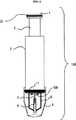
図1は、本発明に係るランセット装置100の外観側面図である。ランセット装置100の外観は、加圧によってランセット装置100の駆動を提供するハンドル1、前記ハンドル1と縦軸に接続され加圧によって前進するピストン2、前記ピストン2に接続され作動するプランジャと、プランジャの瞬間前進移動と復帰動作(トリガー動作)を助けるバネを内部に含むシリンダー3、および真空キャップ4とランセットキャップ5から構成される。前記真空キャップ4とランセットキャップ5はシリンダー3に着脱自在である。前記真空キャップ4は、シリンダー3に挿入する際、真空リング11によって密閉される。本発明においては、前記真空リング11はゴム材質が好ましい。図面符号22は、ハンドル1に着脱自在なカラーリングであって、多数の人が同種のランセット装置100を使用する際、自分のランセット装置を混同せずに区別することができる。本発明においては、前記カラーリング22の色は、虹色が用意されており、そのうち一つの色を選択して前記ハンドル1に嵌めて使用することが好ましい。更に、本発明の真空キャップ4およびランセットキャップ5は、採血過程および採血状態を操作者の目で直接確認できるように透明材質のプラスチック材質が好ましい。前記トリガー動作によってランセットヘッド92bに埋没されている針7が皮膚を瞬間貫通するようになる。図面符号8は、ランセットチャンバーまたは毛細管チャンバーである。 FIG. 1 is an external side view of a
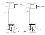
図2Aおよび図2Bは、本発明のランセット装置100が皮膚に密着され、真空あるいは毛細管によって血液を抽出する過程と、抽出された血液をDBDあるいは診断および血液分析装置999の注入口120を介して注入する過程を示す。図面符号4は、皮膚と密着して外部との空気流入を遮断することにより、ピストン2の復帰の間、真空を維持するための真空キャップである。 2A and 2B show a process in which the
図2Aの左図は、血液を採血するためにランセット装置100の真空キャップ4を皮膚66に密着させた状態で、ハンドル1を加圧する動作の例を示す。 The left view of FIG. 2A shows an example of an operation of pressurizing the
図2Aの右図は、持続的な加圧による前記トリガー動作によって皮膚に傷を生じさせ、これによる血液の流出とピストン2の復帰動作による真空発生により、真空キャップ4の内に皮膚66が引っ張られて腫れている様子を示す。傷の部位に生じた血液は、ランセットキャップ5の中央管路によって形成されたランセットチャンバー8に一時保存される。 The right view of FIG. 2A shows that the skin is scratched by the trigger operation by continuous pressurization, and the skin 66 is pulled in the
図2Bは、前記ランセットチャンバー8に一時保存された血液を、DBDあるいは診断および血液分析装置999内に移動させる過程を示す。まず、前記真空キャップ4をシリンダー3から除去した後、注入口120に血液の排出口15を寄り付けた状態でハンドル1を加圧することにより、DBDあるいは診断および血液分析装置999内に血液を移動させるようになる。すなわち、血液の排出口15を注入口120に密着させた後、前記ハンドル1を押すと、ランセットチャンバー8に保存されていた血液が診断および血液分析装置999の血液チャンバー内に流入されるようになる。 FIG. 2B shows a process of moving the blood temporarily stored in the
図3A、3B、3C、および3Dは、本発明のランセット装置100に係る各部の断面図および分解図である。図3Aは、前記ハンドル1とピストン2が組立てられた状態の断面図および分解図である。ピストン2には、ピストンの復帰時にシリンダー3の壁に密着されることにより真空を維持させるためのピストンリング10が嵌められており、選択事項としてハンドル1にはランセット装置100を区分するためのカラーリング22が嵌められる。前記ハンドル1には前記カラーリング22が嵌められる溝1aが形成されており、前記ピストン2の下端部には、ピストン2がシリンダー3から自由に離脱されることを防止するための離脱防止条2aが設けられている。 3A, 3B, 3C, and 3D are a sectional view and an exploded view of each part according to the
図3Bは、前記シリンダー3の断面図および分解図である。図面符号50は抵抗条であり、図面符号51は前進防止条である。前記シリンダー3の末端部には前記真空キャップ4とランセットキャップ5を挿入したときに真空を維持させるための真空リング11とランセットリング12が設けられている。更に、シリンダー3には、前記離脱防止条2aと相互作動してピストン2の離脱を防止するシリンダー条2bが設けられている。 FIG. 3B is a sectional view and an exploded view of the
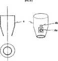
図3Cは、前記真空キャップ4であり、前記真空リング11を介してシリンダー3に嵌められる。図面符号4aは排気口であり、図面符号4bは真空キャップ4内の空気圧力に応じて前記排気口4aを自動開閉させるフラップ要素である。本発明において、前記フラップ要素4bの材質としては、フレキシブルなプラスチックまたはゴム材質が好ましい。本発明においては、前記フラップ要素4bは、血液を採血するために真空キャップ4を皮膚66に密着させた状態で、ハンドル1を加圧する場合、真空キャップ4内の圧力増加に伴って前記フラップ要素4bが真空キャップ4の表面から離脱されることにより前記排気口4aが開放され、ピストン2の復帰動作時、真空キャップ4b内の空気圧力の降下に伴って前記フラップ要素4bがまた真空キャップ4の表面に密着され排気口4aを閉鎖することにより、真空を発生することを特徴とする。 FIG. 3C shows the
図3Dは、前記プランジャ150の断面図および分解図である。プランジャ150は、大きくプランジャシャフト86、放射方向に複数の突出部93が配置されているプランジャヘッド92a、およびプランジャハウジング81から構成されている。また、前記プランジャ150は、前記トリガー動作を誘導するために、バネ1(80)、バネ2(89)、バネ3(91)と共に組立てられる。前記プランジャ150は、トリガー動作によるプランジャヘッド92aの瞬間前進の間、バネ2(89)の圧縮を誘導するためのプランジャシャフト条87とハウジング条90を有する。前記ハウジング条90は組立時にハウジングピン85aとホール85bを介して接続され、熱溶着によってプランジャハウジング81と結合される。シャフトピン86aは、前記プランジャヘッド92a内に形成されているホールに挿入された後、熱溶着によってプランジャヘッド92aと結合される。 FIG. 3D is a cross-sectional view and an exploded view of the plunger 150. The plunger 150 is mainly composed of a plunger shaft 86, a
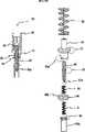
図4は、本発明に係るランセット装置100の全体組立断面図である。ランセット装置100は大きく分けて、ハンドル部200とキャップ部201に分けられる。前記ハンドル部200は、ハンドル1、ピストン2、およびシリンダー3から構成され、キャップ部201は、真空キャップ4とランセットキャップ5から構成される。前記ハンドル部200は、採血時に操作者の親指で加圧するためのハンドル1と、その他の指で把持するピストン2およびシリンダー3を含む部分であって、前記キャップ部201と共に全体のランセット装置を形成する。前記シリンダー3内にはハンドル1の加圧によってトリガー動作を誘導するためのバネ80、89、91、95とプランジャ150が内蔵されている。前記ランセットキャップ5は、皮膚内に挿入するための鋭い端部を有する針7と、これを埋没しているランセットヘッド92bを有する。前記真空キャップ4とランセットキャップ5はシリンダー3に着脱自在である。血液を採取する前に前記シリンダー3のランセットリング12にランセットキャップ5を挿入し、その後にシリンダー3の真空リング11に真空キャップ4を挿入する。 FIG. 4 is an overall assembly sectional view of the
前記ランセットキャップ5は採血された血液を一時保存するためのランセットチャンバー8と、その一時保存された血液を前記診断および分析装置の注入口120に注入するための血液の排出口15を備えたことを特徴とする。前記血液の排出口15は、採血の間は、真空あるいは毛細管によって血液を吸引する入口の役割を兼ねる。本発明において、ランセットキャップ5は使い捨てである。 The
前記プランジャヘッド92aは放射方向に突出した複数の突出部93を有し、前記突出部93はハンドル1の加圧状態でシリンダー3の内壁に設けられた抵抗条50に引っ掛かる。 The
皮膚を穿刺するために、ピストン2がハンドル1から操作者の親指の加圧によって軸方向に押され、これによりプランジャハウジング81も軸方向に押される。このとき、シリンダー3内の抵抗条50は突出部93に引っ掛かって加圧され、突出部93はそれによって形成される抵抗を克服するように弾性的に変形される。 In order to puncture the skin, the
前記加圧する間バネ3(91)は圧縮される。持続的な加圧によって抵抗が克服されると、突出部93が抵抗条50を超え、バネ3(91)の膨張力によってプランジャヘッド92aが速やかに移動し、予定された深さで針7が瞬間的に人の皮膚内に挿入される。前記加圧する間バネ3(91)は圧縮される。 During the pressurization, the spring 3 (91) is compressed. When the resistance is overcome by the continuous pressurization, the protrusion 93 exceeds the resistance strip 50, the
本発明において、前記深さ調節手段は、前記前進防止条51の位置を可変することによりなされる。すなわち、前進防止条51がハンドル1に近接するほど、ランセット装置100の動作時にプランジャシャフト86とプランジャヘッド92aがその分前進できなくなるため、皮膚に挿入される針7の深さがその分浅くなり、逆に、前進防止条51がハンドル1から遠くなるほど、プランジャシャフト86とプランジャヘッド92aがその分もっと前進できるようになるため、皮膚に挿入される針7の深さが深くなることを特徴とする。 In the present invention, the depth adjusting means is made by changing the position of the advancement preventing strip 51. That is, the closer the advancement prevention strip 51 is to the
バネ1(80)とバネ4(95)は、皮膚を穿刺するためにハンドル1を軸方向にある一定以上の力を加えた時にのみピストン2が押されるようにしたり、押されたピストン2の復元を助けたりする駆動バネである。バネ2とバネ3は、前記プランジャ150のトリガー動作をするように設計される。すなわち、バネ3(91)は、加圧の間に突出部93が抵抗条50に引っ掛かって前記ハウジング条90によって圧縮され、抵抗条が克服されるとバネ3(91)の瞬間的膨張によってプランジャヘッド92aを瞬間的に前進させる膨張力を提供する。一方、バネ2(89)は、バネ3(91)の膨張によって瞬間前進したプランジャヘッド92aをまた復帰させるように助ける。 The spring 1 (80) and the spring 4 (95) are configured so that the
すなわち、バネ2(89)は、プランジャヘッド92aの突出部93が抵抗条50を超え、膨張力によって速やかに移動して針7が皮膚内に挿入された後、針がまた皮膚から速やかに抜き出されるようにするためのバネである。プランジャヘッド92aが前記抵抗条50を超える瞬間、プランジャヘッド92aは速やかに前進移動し、このとき前進防止条51によって前記プランジャハウジング81は停止するようになり、プランジャシャフト86とプランジャヘッド92aのみ前進する。結果的に、プランジャシャフト条87とハウジング条90によってバネ2(89)は瞬間的に圧縮される。瞬間的に圧縮されたバネ2(89)の膨張しようとする復元力によってプランジャヘッド92aはシリンダー3内に復帰する。その後、加圧を徐々に解除してピストン2を復帰させると、ピストンリング10による真空が発生するようになり、これは皮膚を真空キャップ4内に吸引して傷の部位から流出される血液がランセットチャンバー8に吸込まれるようにする。このとき、ランセットチャンバー8を介して血液が全部流入されて保存されるので、真空キャップ4を血液によって汚染されない。 That is, the spring 2 (89) has the protrusion 93 of the
本発明における前記ランセットチャンバー8内への血液の流入は、毛細管またはランセット装置100に形成された真空による。 The inflow of blood into the
本発明において、前記ランセットチャンバー8は、ホールの直径が0.05mm〜4mmの注射器針が好ましく、この場合、注射器針が前記針7を取り囲む構造を有する。すなわち、前記注射器針のホールの直径が非常に小さくて毛細管現象が起こりやすい。前記皮膚を貫通するための針7は、前記注射器針のホールの中に埋め立てられ、ランセット装置100の動作時に瞬間前進移動および復帰動作を行なう。また、本発明において、前記ランセットチャンバー8は、円柱状の毛細管と注射器針との結合体であることが更に好ましい。 In the present invention, the
図5A、図5B、および図5Cは、前記ランセットヘッド92bとプランジャヘッド92aとの接続のための幾つかの実施例を示す。前記ランセットキャップ5にはランセットヘッド92bがランセットキャップ5の外部へ自由に離脱しないようにランセットキャップ条65aとヘッド条65bが設けられている。 5A, 5B, and 5C show several embodiments for connecting the
図5Aは、前記トリガー動作中のプランジャヘッド92aが瞬間前進する力によって、ランセットヘッド92bの頭部に衝撃を与えランセットヘッド92bを移動させることにより針7が皮膚を穿刺するようにするランセットキャップ5の実施例であって、この場合、前記ランセットヘッド92bは針7の復帰のためにバネ5(68)が必要である。左図は断面図であり、右図は分解図である。図6Aは、このようなランセットヘッド92bとプランジャヘッド92aを使用したランセット装置100を示す。 FIG. 5A shows a
図5Bは、ランセットヘッド92bの頭部に強磁性体または磁石88bを備え、プランジャヘッド92aの末端にも強磁性体88aを備えることにより、プランジャヘッド92aとランセットヘッド92bとを磁力の引力によって一体化させる実施例を示す。前記トリガー動作中に、プランジャヘッド92aとランセットヘッド92bとが一体化された共に動作する。右図は断面図であり、左図は分解図である。本発明において、前記磁石はネオジム(Neodymium)磁石が好ましい。図6Bは、このようなランセットヘッド92bとプランジャヘッド92aを使用したランセット装置100を示す。図面符号5aは、前記真空キャップ5の表面上に表示された採血すべき血液の最小量を操作者に知らせるためのゲージまたはレベル表示である。 FIG. 5B shows that the
図5Cは、ランセットヘッド92bの頭部にプランジャヘッド92aを物理的に挿入することにより、プランジャヘッド92aとランセットヘッド92bとを一体化させる実施例を示す。 FIG. 5C shows an embodiment in which the
以上、本発明の好適な実施形態を図示および説明してきたが、本発明の技術的範囲は前述の実施形態に限定するものではなく、特許請求の範囲に基づいて定められ、特許請求の範囲において請求する本発明の要旨から外れることなく当該発明が属する技術分野において通常の知識を有する者であれば誰もが多様な変形実施が可能であることは勿論のことであり、該変更した技術は特許請求の範囲に記載された発明の技術的範囲に属するものである。 The preferred embodiments of the present invention have been illustrated and described above, but the technical scope of the present invention is not limited to the above-described embodiments, but is defined based on the scope of the claims. It goes without saying that anyone having ordinary knowledge in the technical field to which the invention belongs without departing from the gist of the claimed invention can be modified in various ways. The invention belongs to the technical scope of the invention described in the claims.
Claims (20)
Translated fromJapanese前記真空キャップは、皮膚と当接する開口部を有し、真空によって皮膚を引っ張り、
前記ランセットキャップは、前記針を取り囲んで前記針によって貫通された皮膚から流出される血液を吸引して保存するためのランセットチャンバーまたは毛細管チャンバーを備え、前記ランセットチャンバーまたは毛細管チャンバーの末端部には、前記ランセットチャンバーまたは毛細管チャンバーに保存された血液を外部へ送り出すための血液の排出口が配置され、前記血液の排出口は、前記皮膚から流出された血液を吸入して前記ランセットチャンバーまたは毛細管チャンバーに保存する血液の吸入口の役割を果たし、
前記ランセットリングは、前記ランセットキャップを前記ランセット装置から着脱自在に構成する
ことを特徴とするランセット装置。In a lancet device including a needle that moves instantaneously forward and returns, including a vacuum cap, a lancet cap, and a lancet ring,
The vacuum cap has an opening that contacts the skin, pulls the skin by a vacuum,
The lancet cap includes a lancet chamber or a capillary chamber for sucking and storing blood flowing out of the skin that surrounds the needle and penetrated by the needle, and at the end of the lancet chamber or the capillary chamber, A blood outlet for delivering blood stored in the lancet chamber or capillary chamber to the outside is arranged, and the blood outlet sucks blood that has flowed out of the skin into the lancet chamber or capillary chamber. Acts as a blood inlet for storing blood,
The lancet ring is configured such that the lancet cap is detachable from the lancet device.
前記ハンドルの加圧によって前進するピストンと、
前記ピストンに接続され作動されるプランジャと、
前記プランジャの瞬間前進移動と復帰動作(トリガー動作)を誘導する複数のバネを内部に含むシリンダーと、をさらに含み、
前記針は、前記プランジャの末端に接続され、前記トリガー動作によって皮膚を一定深さで貫通した後に復帰し、
前記真空キャップは、前記シリンダーの末端に接続され、前記ピストンの復帰時に真空によって皮膚を引っ張り、
前記血液の排出口は、前記ランセットチャンバーまたは毛細管チャンバーの末端に配置され、貫通された皮膚から流出される血液を吸引して前記ランセットチャンバーまたは毛細管チャンバーに保存し、前記ハンドルの加圧によって前記ランセットチャンバーまたは毛細管チャンバーに保存されている血液を外部に送り出すことを特徴とする請求項1に記載のランセット装置。A handle driven by an operator;
A piston that moves forward by pressurizing the handle;
A plunger connected to and actuated by the piston;
A cylinder including a plurality of springs for inducing a momentary forward movement and a return operation (trigger operation) of the plunger;
The needle is connected to the distal end of the plunger and returns after having penetrated the skin at a certain depth by the trigger operation,
The vacuum cap is connected to the end of the cylinder and pulls the skin by a vacuum when the piston returns,
The blood outlet is disposed at the end of the lancet chamber or capillary chamber, sucks blood flowing out from the penetrated skin, stores it in the lancet chamber or capillary chamber, and pressurizes the lancet The lancet device according to claim 1, wherein blood stored in the chamber or the capillary chamber is pumped out.
血液を真空あるいは毛細管によって前記ランセットチャンバーまたは毛細管チャンバーに一時保存するステップと、
前記ランセット装置の血液の排出口を診断および血液分析装置の注入口に寄り付けるステップと、
前記血液の排出口を介して前記ランセットチャンバーまたは毛細管チャンバー内に一時保存された血液を診断および血液分析装置内に移動させるステップと、
を含む血液の注入方法。Of claims 1 to 16 ANote entry methodof blood using the lancet device according to any one,
Temporarily storing blood in the lancet chamber or capillary chamber by vacuum or capillary;
Bringing the blood outlet of the lancet device closer to the inlet of the diagnostic and blood analyzer;
Moving the blood temporarily stored in the lancet chamber or capillary chamber through the blood outlet into the diagnostic and blood analyzer;
Note input methodof blood containing.
血液を真空あるいは毛細管によって前記ランセットチャンバーまたは毛細管チャンバーに一時保存するステップと、
前記一時保存された血液を前記ランセット装置の血液の排出口を介して疾病および糖尿測定用のテストストリップに落とすステップと、
を含む血液の注入方法。Of claims 1 to 16 ANote entry methodof blood using the lancet device according to any one,
Temporarily storing blood in the lancet chamber or capillary chamber by vacuum or capillary;
Dropping the temporarily stored blood through the blood outlet of the lancet device to a test strip for measuring disease and diabetes;
Note input methodof blood containing.
Applications Claiming Priority (3)
| Application Number | Priority Date | Filing Date | Title |
|---|---|---|---|
| KR1020050049571AKR100716015B1 (en) | 2005-06-08 | 2005-06-08 | Lancet device and blood collection and injection method using the same |
| KR10-2005-0049571 | 2005-06-08 | ||
| PCT/KR2006/002195WO2006132504A1 (en) | 2005-06-08 | 2006-06-08 | Lancet device and method for sampling and injecting blood using the lancet device |
Publications (2)
| Publication Number | Publication Date |
|---|---|
| JP2008541983A JP2008541983A (en) | 2008-11-27 |
| JP4970433B2true JP4970433B2 (en) | 2012-07-04 |
Family
ID=37498669
Family Applications (1)
| Application Number | Title | Priority Date | Filing Date |
|---|---|---|---|
| JP2008515627AActiveJP4970433B2 (en) | 2005-06-08 | 2006-06-08 | Lancet device and blood injection method using the same |
Country Status (6)
| Country | Link |
|---|---|
| US (1) | US20090299224A1 (en) |
| EP (1) | EP1895904A4 (en) |
| JP (1) | JP4970433B2 (en) |
| KR (1) | KR100716015B1 (en) |
| CN (1) | CN101203177B (en) |
| WO (1) | WO2006132504A1 (en) |
Families Citing this family (56)
| Publication number | Priority date | Publication date | Assignee | Title |
|---|---|---|---|---|
| JP4871083B2 (en)* | 2006-09-27 | 2012-02-08 | テルモ株式会社 | Body fluid collection unit |
| USD586465S1 (en) | 2008-05-09 | 2009-02-10 | Lifescan Scotland Limited | Handheld lancing device |
| US8454533B2 (en) | 2008-05-09 | 2013-06-04 | Lifescan Scotland Limited | Lancing devices and methods |
| USD586916S1 (en) | 2008-05-09 | 2009-02-17 | Lifescan Scotland, Ltd. | Handheld lancing device |
| US8932314B2 (en) | 2008-05-09 | 2015-01-13 | Lifescan Scotland Limited | Prime and fire lancing device with contacting bias drive and method |
| CN102245104B (en)* | 2008-12-09 | 2014-05-14 | 松下健康医疗器械株式会社 | Pressure reduction mechanism, puncture device and blood analysis device |
| US20100256524A1 (en) | 2009-03-02 | 2010-10-07 | Seventh Sense Biosystems, Inc. | Techniques and devices associated with blood sampling |
| JP5540617B2 (en)* | 2009-09-10 | 2014-07-02 | ニプロ株式会社 | Disposable blood collection device |
| US8460211B2 (en)* | 2010-01-19 | 2013-06-11 | Christopher A. Jacobs | Vacuum assisted lancing system with bidirectional mechanism and method for blood extraction with minimal pain |
| US8657763B2 (en) | 2010-01-19 | 2014-02-25 | Christopher A. Jacobs | Vacuum assisted lancing system with elective vacuum release and method for blood extraction with minimal pain |
| EP2542886A1 (en)* | 2010-03-05 | 2013-01-09 | B. Braun Melsungen AG | System and method for monitoring at least one blood parameter |
| US20130158482A1 (en) | 2010-07-26 | 2013-06-20 | Seventh Sense Biosystems, Inc. | Rapid delivery and/or receiving of fluids |
| WO2012021801A2 (en) | 2010-08-13 | 2012-02-16 | Seventh Sense Biosystems, Inc. | Systems and techniques for monitoring subjects |
| WO2012064802A1 (en)* | 2010-11-09 | 2012-05-18 | Seventh Sense Biosystems, Inc. | Systems and interfaces for blood sampling |
| CN103874461B (en) | 2011-04-29 | 2017-05-10 | 第七感生物系统有限公司 | Devices for collecting and/or manipulating blood spots or other bodily fluids |
| KR102013466B1 (en) | 2011-04-29 | 2019-08-22 | 세븐쓰 센스 바이오시스템즈, 인크. | Delivering and/or receiving fluids |
| WO2012149155A1 (en) | 2011-04-29 | 2012-11-01 | Seventh Sense Biosystems, Inc. | Systems and methods for collecting fluid from a subject |
| US20130158468A1 (en) | 2011-12-19 | 2013-06-20 | Seventh Sense Biosystems, Inc. | Delivering and/or receiving material with respect to a subject surface |
| US20130211289A1 (en) | 2012-01-25 | 2013-08-15 | Tasso, Inc. | Handheld Device for Drawing, Collecting, and Analyzing Bodily Fluid |
| WO2014110250A1 (en)* | 2013-01-09 | 2014-07-17 | Modern Meadow, Inc. | Methods and devices for preparing and continuously printing multicellular cylinders onto biocompatible substrates |
| EP2986218B1 (en)* | 2013-04-15 | 2017-12-20 | Becton, Dickinson and Company | Biological fluid collection device and biological fluid separation and testing system |
| WO2015038988A1 (en) | 2013-09-13 | 2015-03-19 | Modern Meadow, Inc. | Edible and animal-product-free microcarriers for engineered meat |
| CN104856699B (en)* | 2014-05-21 | 2018-02-13 | 广州市恒诚空调设备维修有限公司 | A kind of bullet unloads formula blood collecting pen structure |
| EP2965779A1 (en)* | 2014-07-07 | 2016-01-13 | MT Derm GmbH | Application module for a handheld device for repeated application of an application element to a human or an animal skin and hand-held device |
| CN106999120B (en) | 2014-08-01 | 2021-05-14 | 塔索公司 | Devices, systems, and methods for gravity-enhanced microfluidic collection, handling, and delivery of liquids |
| CN104483368B (en)* | 2014-12-03 | 2017-02-22 | 上海应用技术学院 | Portable electrolyte analysis device with blood sampling micro-needle array |
| CN104914195B (en)* | 2015-05-28 | 2017-05-24 | 国网山东省电力公司电力科学研究院 | Standard gas preparation device and method |
| US10154809B2 (en) | 2015-06-24 | 2018-12-18 | University Of Virginia Patent Foundation | Test strip device and related methods thereof |
| JP7142569B2 (en) | 2015-09-09 | 2022-09-27 | ドローブリッジ ヘルス,インコーポレイテッド | Systems, methods and devices for sample collection, stabilization and storage |
| EP3337923B2 (en) | 2015-09-21 | 2023-01-04 | Modern Meadow, Inc. | Fiber reinforced tissue composites |
| KR20170096093A (en) | 2016-02-15 | 2017-08-23 | 브렌던 패트릭 퍼셀 | Composite biofabricated material |
| CN105894786A (en)* | 2016-03-31 | 2016-08-24 | 国网山东省电力公司鄄城县供电公司 | Client electricity information collection simulation system for electricity marketing |
| CN105913170A (en)* | 2016-03-31 | 2016-08-31 | 国网山东省电力公司鄄城县供电公司 | Hand-held intelligent ammeter information acquisition equipment for electric power marketing |
| CN105742980A (en)* | 2016-03-31 | 2016-07-06 | 国网山东省电力公司鄄城县供电公司 | Power distribution cabinet for electric marketing |
| CN105818573A (en)* | 2016-04-01 | 2016-08-03 | 陈庭 | No-break pencil |
| CN105708477B (en)* | 2016-04-08 | 2018-11-09 | 武汉乐享天伦科技有限公司 | A kind of integrated blood glucose meter of Portable negative-pressure blood sampling detection |
| CN105796117A (en)* | 2016-04-08 | 2016-07-27 | 杜东 | Hypodynia blood collection and detection integrated glucose meter |
| CN105852878B (en)* | 2016-04-08 | 2020-05-22 | 武汉乐享天伦科技有限公司 | Blood glucose meter with data transmission function |
| CN105919604B (en)* | 2016-04-08 | 2020-05-26 | 武汉乐享天伦科技有限公司 | Portable blood sampling detects integrative blood glucose meter |
| CN106324235B (en)* | 2016-08-12 | 2018-07-13 | 上海移宇科技股份有限公司 | The fully integrated bodily fluid sampling of single step analyzes pen |
| CN108113713A (en)* | 2016-11-29 | 2018-06-05 | 韩国电子通信研究院 | collecting device for body fluids |
| KR102482488B1 (en)* | 2016-11-29 | 2022-12-30 | 한국전자통신연구원 | Apparatus for collecting body fluids |
| KR101762345B1 (en)* | 2017-01-04 | 2017-07-27 | 한진희 | Operating method for gradation eye brow |
| GB2590813B (en) | 2017-01-10 | 2021-10-27 | Drawbridge Health Inc | Devices, systems, and methods for sample collection |
| CN107582387A (en)* | 2017-08-29 | 2018-01-16 | 丁允志 | A kind of electronic bloodletting device |
| CN107736892A (en)* | 2017-11-09 | 2018-02-27 | 杨智伟 | Sealed blood sampling device for medical blood test |
| AU2018253595A1 (en) | 2017-11-13 | 2019-05-30 | Modern Meadow, Inc. | Biofabricated leather articles having zonal properties |
| KR102740796B1 (en) | 2018-12-24 | 2024-12-09 | 엘지디스플레이 주식회사 | Electroluminance Lighting Device |
| CA3121853A1 (en) | 2019-01-17 | 2020-07-23 | Modern Meadow, Inc. | Layered collagen materials and methods of making the same |
| KR102265307B1 (en)* | 2019-10-04 | 2021-06-16 | 에임 주식회사 | Unit for collecting and ejecting blood |
| KR20210066481A (en)* | 2019-11-28 | 2021-06-07 | 가톨릭관동대학교산학협력단 | Disposable blood collection device |
| CN112043290B (en)* | 2020-10-09 | 2021-05-11 | 普昂(杭州)医疗科技股份有限公司 | Negative pressure blood sampling pen |
| CN112022170B (en)* | 2020-10-09 | 2021-06-11 | 普昂(杭州)医疗科技股份有限公司 | Blood sampling pen capable of delaying emission after triggering |
| CN114533058A (en)* | 2020-11-25 | 2022-05-27 | 德诺杰亿(北京)生物科技有限公司 | Disposable hemostix |
| CN114366097B (en)* | 2022-01-11 | 2023-10-20 | 梁栋才 | Nephrology department hemodialysis sampler |
| CN114569126B (en)* | 2022-04-29 | 2022-10-28 | 深圳市帝迈生物技术有限公司 | Trace sampling tube and blood sampling method thereof |
Family Cites Families (19)
| Publication number | Priority date | Publication date | Assignee | Title |
|---|---|---|---|---|
| US4653513A (en)* | 1985-08-09 | 1987-03-31 | Dombrowski Mitchell P | Blood sampler |
| US4895147A (en)* | 1988-10-28 | 1990-01-23 | Sherwood Medical Company | Lancet injector |
| GB9207120D0 (en)* | 1992-04-01 | 1992-05-13 | Owen Mumford Ltd | Improvements relating to blood sampling devices |
| US5582184A (en)* | 1993-10-13 | 1996-12-10 | Integ Incorporated | Interstitial fluid collection and constituent measurement |
| JP3393920B2 (en)* | 1993-12-09 | 2003-04-07 | 富士写真フイルム株式会社 | Wearing equipment for small-volume fixed-volume blood sampling points |
| US6332871B1 (en)* | 1996-05-17 | 2001-12-25 | Amira Medical | Blood and interstitial fluid sampling device |
| US5873887A (en) | 1996-10-25 | 1999-02-23 | Bayer Corporation | Blood sampling device |
| US5871494A (en)* | 1997-12-04 | 1999-02-16 | Hewlett-Packard Company | Reproducible lancing for sampling blood |
| JP2000000425A (en)* | 1998-06-12 | 2000-01-07 | Toyobo Co Ltd | Treatment of low-concentration gaseous organic solvent and its treatment apparatus |
| US6152942A (en)* | 1999-06-14 | 2000-11-28 | Bayer Corporation | Vacuum assisted lancing device |
| US6283982B1 (en)* | 1999-10-19 | 2001-09-04 | Facet Technologies, Inc. | Lancing device and method of sample collection |
| US7780610B2 (en)* | 2000-05-01 | 2010-08-24 | Terumo Kabushiki Kaisha | Component measuring instrument and chip |
| US20020188223A1 (en)* | 2001-06-08 | 2002-12-12 | Edward Perez | Devices and methods for the expression of bodily fluids from an incision |
| ATE343349T1 (en)* | 2001-06-08 | 2006-11-15 | Hoffmann La Roche | DEVICES FOR EXPRESSING BODY FLUID FROM AN INCISION |
| EP1396226B1 (en)* | 2001-06-11 | 2013-08-21 | ARKRAY, Inc. | Measuring apparatus comprising a puncturing element integration mounting body |
| DE10222235A1 (en)* | 2002-05-16 | 2003-11-27 | Roche Diagnostics Gmbh | Blood Collection system |
| EP1621132B1 (en)* | 2003-06-27 | 2007-03-07 | Ehrfeld Mikrotechnik AG in Insolvenz | Device and method for sampling and analysing body fluids |
| KR100522157B1 (en)* | 2003-10-01 | 2005-10-18 | 차은종 | Vacuum assisted auto-lancing device |
| WO2005077274A1 (en)* | 2004-02-06 | 2005-08-25 | Bayer Healthcare Llc | Method and apparatus for measuring an analyte in a body fluid |
- 2005
- 2005-06-08KRKR1020050049571Apatent/KR100716015B1/ennot_activeExpired - Fee Related
- 2006
- 2006-06-08JPJP2008515627Apatent/JP4970433B2/enactiveActive
- 2006-06-08EPEP06747499Apatent/EP1895904A4/ennot_activeWithdrawn
- 2006-06-08WOPCT/KR2006/002195patent/WO2006132504A1/enactiveApplication Filing
- 2006-06-08USUS11/921,907patent/US20090299224A1/ennot_activeAbandoned
- 2006-06-08CNCN2006800202365Apatent/CN101203177B/enactiveActive
Also Published As
| Publication number | Publication date |
|---|---|
| US20090299224A1 (en) | 2009-12-03 |
| WO2006132504A1 (en) | 2006-12-14 |
| EP1895904A4 (en) | 2009-12-02 |
| KR100716015B1 (en) | 2007-05-08 |
| JP2008541983A (en) | 2008-11-27 |
| EP1895904A1 (en) | 2008-03-12 |
| KR20060128274A (en) | 2006-12-14 |
| CN101203177B (en) | 2010-05-19 |
| CN101203177A (en) | 2008-06-18 |
Similar Documents
| Publication | Publication Date | Title |
|---|---|---|
| JP4970433B2 (en) | Lancet device and blood injection method using the same | |
| US6030399A (en) | Fluid jet blood sampling device and methods | |
| CN102802524B (en) | Vacuum-assisted puncture system and method for drawing blood with minimal pain | |
| US7549972B2 (en) | Tool for extracting vitreous samples from an eye | |
| JP3574800B2 (en) | Lancet system | |
| EP1245187B1 (en) | Split pressure ring for lancing device and blood drawing system | |
| US5662127A (en) | Self-contained blood withdrawal apparatus and method | |
| ES2384462T3 (en) | Allergy test device | |
| CN103068307B (en) | Devices used to collect blood samples | |
| EP2734162B1 (en) | Device for the insertion of an ear pressure equalizing tube | |
| US20150342509A1 (en) | Needle-Free Blood Draw | |
| US20110152715A1 (en) | Biopsy needle with vacuum assist | |
| US20080097241A1 (en) | Sampling device | |
| US20020169393A1 (en) | Method and apparatus for obtaining blood for diagnostic tests | |
| CN103068434A (en) | A removable flash chamber | |
| CZ20024006A3 (en) | Cap for incision device and incision device per se | |
| US20230301566A1 (en) | Device, method, and system for collection of blood | |
| JP4048219B2 (en) | Body fluid sampling device | |
| US20020045912A1 (en) | Fluid jet blood sampling device and methods | |
| WO2014005058A1 (en) | Novel auto-aspirating syringe | |
| CN110167452A (en) | Apparatus and method for withdrawing and collecting tissue samples | |
| JP2003225227A (en) | Collection container, collection device and collection method | |
| CN108338793B (en) | A kind of venous blood collection needle | |
| CN100369641C (en) | medical equipment | |
| JP2021535764A (en) | Capillary blood collection device |
Legal Events
| Date | Code | Title | Description |
|---|---|---|---|
| A711 | Notification of change in applicant | Free format text:JAPANESE INTERMEDIATE CODE: A711 Effective date:20091020 | |
| A131 | Notification of reasons for refusal | Free format text:JAPANESE INTERMEDIATE CODE: A131 Effective date:20100713 | |
| A601 | Written request for extension of time | Free format text:JAPANESE INTERMEDIATE CODE: A601 Effective date:20101013 | |
| A602 | Written permission of extension of time | Free format text:JAPANESE INTERMEDIATE CODE: A602 Effective date:20101020 | |
| A521 | Request for written amendment filed | Free format text:JAPANESE INTERMEDIATE CODE: A523 Effective date:20101108 | |
| A131 | Notification of reasons for refusal | Free format text:JAPANESE INTERMEDIATE CODE: A131 Effective date:20110531 | |
| A521 | Request for written amendment filed | Free format text:JAPANESE INTERMEDIATE CODE: A523 Effective date:20110831 | |
| RD03 | Notification of appointment of power of attorney | Free format text:JAPANESE INTERMEDIATE CODE: A7423 Effective date:20110930 | |
| A131 | Notification of reasons for refusal | Free format text:JAPANESE INTERMEDIATE CODE: A131 Effective date:20111004 | |
| A521 | Request for written amendment filed | Free format text:JAPANESE INTERMEDIATE CODE: A523 Effective date:20111226 | |
| A131 | Notification of reasons for refusal | Free format text:JAPANESE INTERMEDIATE CODE: A131 Effective date:20120207 | |
| A521 | Request for written amendment filed | Free format text:JAPANESE INTERMEDIATE CODE: A523 Effective date:20120208 | |
| TRDD | Decision of grant or rejection written | ||
| A01 | Written decision to grant a patent or to grant a registration (utility model) | Free format text:JAPANESE INTERMEDIATE CODE: A01 Effective date:20120306 | |
| A01 | Written decision to grant a patent or to grant a registration (utility model) | Free format text:JAPANESE INTERMEDIATE CODE: A01 | |
| A61 | First payment of annual fees (during grant procedure) | Free format text:JAPANESE INTERMEDIATE CODE: A61 Effective date:20120404 | |
| FPAY | Renewal fee payment (event date is renewal date of database) | Free format text:PAYMENT UNTIL: 20150413 Year of fee payment:3 | |
| R150 | Certificate of patent or registration of utility model | Ref document number:4970433 Country of ref document:JP Free format text:JAPANESE INTERMEDIATE CODE: R150 Free format text:JAPANESE INTERMEDIATE CODE: R150 | |
| R250 | Receipt of annual fees | Free format text:JAPANESE INTERMEDIATE CODE: R250 | |
| R250 | Receipt of annual fees | Free format text:JAPANESE INTERMEDIATE CODE: R250 | |
| R250 | Receipt of annual fees | Free format text:JAPANESE INTERMEDIATE CODE: R250 | |
| R250 | Receipt of annual fees | Free format text:JAPANESE INTERMEDIATE CODE: R250 | |
| R250 | Receipt of annual fees | Free format text:JAPANESE INTERMEDIATE CODE: R250 | |
| R250 | Receipt of annual fees | Free format text:JAPANESE INTERMEDIATE CODE: R250 | |
| R250 | Receipt of annual fees | Free format text:JAPANESE INTERMEDIATE CODE: R250 | |
| R250 | Receipt of annual fees | Free format text:JAPANESE INTERMEDIATE CODE: R250 | |
| S111 | Request for change of ownership or part of ownership | Free format text:JAPANESE INTERMEDIATE CODE: R313113 | |
| S531 | Written request for registration of change of domicile | Free format text:JAPANESE INTERMEDIATE CODE: R313531 | |
| R350 | Written notification of registration of transfer | Free format text:JAPANESE INTERMEDIATE CODE: R350 | |
| R250 | Receipt of annual fees | Free format text:JAPANESE INTERMEDIATE CODE: R250 | |
| R250 | Receipt of annual fees | Free format text:JAPANESE INTERMEDIATE CODE: R250 | |
| R250 | Receipt of annual fees | Free format text:JAPANESE INTERMEDIATE CODE: R250 |