JP4964840B2 - Optical recording medium - Google Patents
Optical recording mediumDownload PDFInfo
- Publication number
- JP4964840B2 JP4964840B2JP2008189003AJP2008189003AJP4964840B2JP 4964840 B2JP4964840 B2JP 4964840B2JP 2008189003 AJP2008189003 AJP 2008189003AJP 2008189003 AJP2008189003 AJP 2008189003AJP 4964840 B2JP4964840 B2JP 4964840B2
- Authority
- JP
- Japan
- Prior art keywords
- area
- lead
- recording medium
- user data
- wobble
- Prior art date
- Legal status (The legal status is an assumption and is not a legal conclusion. Google has not performed a legal analysis and makes no representation as to the accuracy of the status listed.)
- Expired - Lifetime
Links
Images


Classifications
- G—PHYSICS
- G11—INFORMATION STORAGE
- G11B—INFORMATION STORAGE BASED ON RELATIVE MOVEMENT BETWEEN RECORD CARRIER AND TRANSDUCER
- G11B27/00—Editing; Indexing; Addressing; Timing or synchronising; Monitoring; Measuring tape travel
- G11B27/10—Indexing; Addressing; Timing or synchronising; Measuring tape travel
- G11B27/19—Indexing; Addressing; Timing or synchronising; Measuring tape travel by using information detectable on the record carrier
- G11B27/24—Indexing; Addressing; Timing or synchronising; Measuring tape travel by using information detectable on the record carrier by sensing features on the record carrier other than the transducing track ; sensing signals or marks recorded by another method than the main recording
- G—PHYSICS
- G11—INFORMATION STORAGE
- G11B—INFORMATION STORAGE BASED ON RELATIVE MOVEMENT BETWEEN RECORD CARRIER AND TRANSDUCER
- G11B20/00—Signal processing not specific to the method of recording or reproducing; Circuits therefor
- G11B20/10—Digital recording or reproducing
- G11B20/10009—Improvement or modification of read or write signals
- G11B20/10222—Improvement or modification of read or write signals clock-related aspects, e.g. phase or frequency adjustment or bit synchronisation
- G11B20/1024—Improvement or modification of read or write signals clock-related aspects, e.g. phase or frequency adjustment or bit synchronisation wherein a phase-locked loop [PLL] is used
- G—PHYSICS
- G11—INFORMATION STORAGE
- G11B—INFORMATION STORAGE BASED ON RELATIVE MOVEMENT BETWEEN RECORD CARRIER AND TRANSDUCER
- G11B20/00—Signal processing not specific to the method of recording or reproducing; Circuits therefor
- G11B20/10—Digital recording or reproducing
- G11B20/12—Formatting, e.g. arrangement of data block or words on the record carriers
- G11B20/1217—Formatting, e.g. arrangement of data block or words on the record carriers on discs
- G—PHYSICS
- G11—INFORMATION STORAGE
- G11B—INFORMATION STORAGE BASED ON RELATIVE MOVEMENT BETWEEN RECORD CARRIER AND TRANSDUCER
- G11B20/00—Signal processing not specific to the method of recording or reproducing; Circuits therefor
- G11B20/10—Digital recording or reproducing
- G11B20/14—Digital recording or reproducing using self-clocking codes
- G—PHYSICS
- G11—INFORMATION STORAGE
- G11B—INFORMATION STORAGE BASED ON RELATIVE MOVEMENT BETWEEN RECORD CARRIER AND TRANSDUCER
- G11B7/00—Recording or reproducing by optical means, e.g. recording using a thermal beam of optical radiation by modifying optical properties or the physical structure, reproducing using an optical beam at lower power by sensing optical properties; Record carriers therefor
- G11B7/004—Recording, reproducing or erasing methods; Read, write or erase circuits therefor
- G11B7/005—Reproducing
- G11B7/0053—Reproducing non-user data, e.g. wobbled address, prepits, BCA
- G—PHYSICS
- G11—INFORMATION STORAGE
- G11B—INFORMATION STORAGE BASED ON RELATIVE MOVEMENT BETWEEN RECORD CARRIER AND TRANSDUCER
- G11B7/00—Recording or reproducing by optical means, e.g. recording using a thermal beam of optical radiation by modifying optical properties or the physical structure, reproducing using an optical beam at lower power by sensing optical properties; Record carriers therefor
- G11B7/007—Arrangement of the information on the record carrier, e.g. form of tracks, actual track shape, e.g. wobbled, or cross-section, e.g. v-shaped; Sequential information structures, e.g. sectoring or header formats within a track
- G11B7/00718—Groove and land recording, i.e. user data recorded both in the grooves and on the lands
- G—PHYSICS
- G11—INFORMATION STORAGE
- G11B—INFORMATION STORAGE BASED ON RELATIVE MOVEMENT BETWEEN RECORD CARRIER AND TRANSDUCER
- G11B7/00—Recording or reproducing by optical means, e.g. recording using a thermal beam of optical radiation by modifying optical properties or the physical structure, reproducing using an optical beam at lower power by sensing optical properties; Record carriers therefor
- G11B7/007—Arrangement of the information on the record carrier, e.g. form of tracks, actual track shape, e.g. wobbled, or cross-section, e.g. v-shaped; Sequential information structures, e.g. sectoring or header formats within a track
- G11B7/0079—Zoned data area, e.g. having different data structures or formats for the user data within data layer, Zone Constant Linear Velocity [ZCLV], Zone Constant Angular Velocity [ZCAV], carriers with RAM and ROM areas
- G—PHYSICS
- G11—INFORMATION STORAGE
- G11B—INFORMATION STORAGE BASED ON RELATIVE MOVEMENT BETWEEN RECORD CARRIER AND TRANSDUCER
- G11B7/00—Recording or reproducing by optical means, e.g. recording using a thermal beam of optical radiation by modifying optical properties or the physical structure, reproducing using an optical beam at lower power by sensing optical properties; Record carriers therefor
- G11B7/08—Disposition or mounting of heads or light sources relatively to record carriers
- G11B7/085—Disposition or mounting of heads or light sources relatively to record carriers with provision for moving the light beam into, or out of, its operative position or across tracks, otherwise than during the transducing operation, e.g. for adjustment or preliminary positioning or track change or selection
- G11B7/08505—Methods for track change, selection or preliminary positioning by moving the head
- G11B7/08511—Methods for track change, selection or preliminary positioning by moving the head with focus pull-in only
- G—PHYSICS
- G11—INFORMATION STORAGE
- G11B—INFORMATION STORAGE BASED ON RELATIVE MOVEMENT BETWEEN RECORD CARRIER AND TRANSDUCER
- G11B7/00—Recording or reproducing by optical means, e.g. recording using a thermal beam of optical radiation by modifying optical properties or the physical structure, reproducing using an optical beam at lower power by sensing optical properties; Record carriers therefor
- G11B7/08—Disposition or mounting of heads or light sources relatively to record carriers
- G11B7/09—Disposition or mounting of heads or light sources relatively to record carriers with provision for moving the light beam or focus plane for the purpose of maintaining alignment of the light beam relative to the record carrier during transducing operation, e.g. to compensate for surface irregularities of the latter or for track following
- G11B7/095—Disposition or mounting of heads or light sources relatively to record carriers with provision for moving the light beam or focus plane for the purpose of maintaining alignment of the light beam relative to the record carrier during transducing operation, e.g. to compensate for surface irregularities of the latter or for track following specially adapted for discs, e.g. for compensation of eccentricity or wobble
- G11B7/0953—Disposition or mounting of heads or light sources relatively to record carriers with provision for moving the light beam or focus plane for the purpose of maintaining alignment of the light beam relative to the record carrier during transducing operation, e.g. to compensate for surface irregularities of the latter or for track following specially adapted for discs, e.g. for compensation of eccentricity or wobble to compensate for eccentricity of the disc or disc tracks
- G—PHYSICS
- G11—INFORMATION STORAGE
- G11B—INFORMATION STORAGE BASED ON RELATIVE MOVEMENT BETWEEN RECORD CARRIER AND TRANSDUCER
- G11B7/00—Recording or reproducing by optical means, e.g. recording using a thermal beam of optical radiation by modifying optical properties or the physical structure, reproducing using an optical beam at lower power by sensing optical properties; Record carriers therefor
- G11B7/24—Record carriers characterised by shape, structure or physical properties, or by the selection of the material
- G11B7/2403—Layers; Shape, structure or physical properties thereof
- G11B7/24035—Recording layers
- G11B7/24038—Multiple laminated recording layers
- G—PHYSICS
- G11—INFORMATION STORAGE
- G11B—INFORMATION STORAGE BASED ON RELATIVE MOVEMENT BETWEEN RECORD CARRIER AND TRANSDUCER
- G11B7/00—Recording or reproducing by optical means, e.g. recording using a thermal beam of optical radiation by modifying optical properties or the physical structure, reproducing using an optical beam at lower power by sensing optical properties; Record carriers therefor
- G11B7/24—Record carriers characterised by shape, structure or physical properties, or by the selection of the material
- G11B7/2407—Tracks or pits; Shape, structure or physical properties thereof
- G11B7/24073—Tracks
- G11B7/24082—Meandering
- G—PHYSICS
- G11—INFORMATION STORAGE
- G11B—INFORMATION STORAGE BASED ON RELATIVE MOVEMENT BETWEEN RECORD CARRIER AND TRANSDUCER
- G11B7/00—Recording or reproducing by optical means, e.g. recording using a thermal beam of optical radiation by modifying optical properties or the physical structure, reproducing using an optical beam at lower power by sensing optical properties; Record carriers therefor
- G11B2007/0003—Recording, reproducing or erasing systems characterised by the structure or type of the carrier
- G11B2007/0009—Recording, reproducing or erasing systems characterised by the structure or type of the carrier for carriers having data stored in three dimensions, e.g. volume storage
- G11B2007/0013—Recording, reproducing or erasing systems characterised by the structure or type of the carrier for carriers having data stored in three dimensions, e.g. volume storage for carriers having multiple discrete layers
- G—PHYSICS
- G11—INFORMATION STORAGE
- G11B—INFORMATION STORAGE BASED ON RELATIVE MOVEMENT BETWEEN RECORD CARRIER AND TRANSDUCER
- G11B20/00—Signal processing not specific to the method of recording or reproducing; Circuits therefor
- G11B20/10—Digital recording or reproducing
- G11B20/12—Formatting, e.g. arrangement of data block or words on the record carriers
- G11B20/1217—Formatting, e.g. arrangement of data block or words on the record carriers on discs
- G11B2020/1218—Formatting, e.g. arrangement of data block or words on the record carriers on discs wherein the formatting concerns a specific area of the disc
- G11B2020/1238—Formatting, e.g. arrangement of data block or words on the record carriers on discs wherein the formatting concerns a specific area of the disc track, i.e. the entire a spirally or concentrically arranged path on which the recording marks are located
- G11B2020/1239—Formatting, e.g. arrangement of data block or words on the record carriers on discs wherein the formatting concerns a specific area of the disc track, i.e. the entire a spirally or concentrically arranged path on which the recording marks are located the track being a pregroove, e.g. the wobbled track of a recordable optical disc
- G—PHYSICS
- G11—INFORMATION STORAGE
- G11B—INFORMATION STORAGE BASED ON RELATIVE MOVEMENT BETWEEN RECORD CARRIER AND TRANSDUCER
- G11B20/00—Signal processing not specific to the method of recording or reproducing; Circuits therefor
- G11B20/10—Digital recording or reproducing
- G11B20/12—Formatting, e.g. arrangement of data block or words on the record carriers
- G11B2020/1264—Formatting, e.g. arrangement of data block or words on the record carriers wherein the formatting concerns a specific kind of data
- G11B2020/1265—Control data, system data or management information, i.e. data used to access or process user data
- G11B2020/1287—Synchronisation pattern, e.g. VCO fields
- G—PHYSICS
- G11—INFORMATION STORAGE
- G11B—INFORMATION STORAGE BASED ON RELATIVE MOVEMENT BETWEEN RECORD CARRIER AND TRANSDUCER
- G11B2220/00—Record carriers by type
- G11B2220/20—Disc-shaped record carriers
- G11B2220/21—Disc-shaped record carriers characterised in that the disc is of read-only, rewritable, or recordable type
- G11B2220/215—Recordable discs
- G11B2220/216—Rewritable discs
- G—PHYSICS
- G11—INFORMATION STORAGE
- G11B—INFORMATION STORAGE BASED ON RELATIVE MOVEMENT BETWEEN RECORD CARRIER AND TRANSDUCER
- G11B2220/00—Record carriers by type
- G11B2220/20—Disc-shaped record carriers
- G11B2220/23—Disc-shaped record carriers characterised in that the disc has a specific layer structure
- G11B2220/235—Multilayer discs, i.e. multiple recording layers accessed from the same side
- G—PHYSICS
- G11—INFORMATION STORAGE
- G11B—INFORMATION STORAGE BASED ON RELATIVE MOVEMENT BETWEEN RECORD CARRIER AND TRANSDUCER
- G11B2220/00—Record carriers by type
- G11B2220/20—Disc-shaped record carriers
- G11B2220/25—Disc-shaped record carriers characterised in that the disc is based on a specific recording technology
- G11B2220/2537—Optical discs
- G11B2220/2562—DVDs [digital versatile discs]; Digital video discs; MMCDs; HDCDs
- G11B2220/2575—DVD-RAMs
- G—PHYSICS
- G11—INFORMATION STORAGE
- G11B—INFORMATION STORAGE BASED ON RELATIVE MOVEMENT BETWEEN RECORD CARRIER AND TRANSDUCER
- G11B27/00—Editing; Indexing; Addressing; Timing or synchronising; Monitoring; Measuring tape travel
- G11B27/10—Indexing; Addressing; Timing or synchronising; Measuring tape travel
- G11B27/19—Indexing; Addressing; Timing or synchronising; Measuring tape travel by using information detectable on the record carrier
- G11B27/28—Indexing; Addressing; Timing or synchronising; Measuring tape travel by using information detectable on the record carrier by using information signals recorded by the same method as the main recording
- G11B27/30—Indexing; Addressing; Timing or synchronising; Measuring tape travel by using information detectable on the record carrier by using information signals recorded by the same method as the main recording on the same track as the main recording
- G11B27/3027—Indexing; Addressing; Timing or synchronising; Measuring tape travel by using information detectable on the record carrier by using information signals recorded by the same method as the main recording on the same track as the main recording used signal is digitally coded
- G—PHYSICS
- G11—INFORMATION STORAGE
- G11B—INFORMATION STORAGE BASED ON RELATIVE MOVEMENT BETWEEN RECORD CARRIER AND TRANSDUCER
- G11B7/00—Recording or reproducing by optical means, e.g. recording using a thermal beam of optical radiation by modifying optical properties or the physical structure, reproducing using an optical beam at lower power by sensing optical properties; Record carriers therefor
- G11B7/002—Recording, reproducing or erasing systems characterised by the shape or form of the carrier
- G11B7/0037—Recording, reproducing or erasing systems characterised by the shape or form of the carrier with discs
- G—PHYSICS
- G11—INFORMATION STORAGE
- G11B—INFORMATION STORAGE BASED ON RELATIVE MOVEMENT BETWEEN RECORD CARRIER AND TRANSDUCER
- G11B7/00—Recording or reproducing by optical means, e.g. recording using a thermal beam of optical radiation by modifying optical properties or the physical structure, reproducing using an optical beam at lower power by sensing optical properties; Record carriers therefor
- G11B7/007—Arrangement of the information on the record carrier, e.g. form of tracks, actual track shape, e.g. wobbled, or cross-section, e.g. v-shaped; Sequential information structures, e.g. sectoring or header formats within a track
- G11B7/00736—Auxiliary data, e.g. lead-in, lead-out, Power Calibration Area [PCA], Burst Cutting Area [BCA], control information
Landscapes
- Engineering & Computer Science (AREA)
- Signal Processing (AREA)
- Software Systems (AREA)
- Theoretical Computer Science (AREA)
- Optical Recording Or Reproduction (AREA)
- Optical Record Carriers And Manufacture Thereof (AREA)
- Signal Processing For Digital Recording And Reproducing (AREA)
Description
Translated fromJapanese本発明は光記録媒体に係り、特に使用者データ領域とリードアウト領域のグルーブの少なくとも一側面にウォッブルを備えて使用者データ領域とリードアウト領域のウォッブル特性を異なるように形成した光記録媒体に関する。 The present invention relates to an optical recording medium, and more particularly, to an optical recording medium in which wobbles are provided on at least one side of a groove of a user data area and a lead-out area so that wobble characteristics of the user data area and the lead-out area are different. .
一般に光記録媒体は非接触式で情報を記録及び/または再生する光ピックアップ装置の情報記録媒体として広く採用され、情報記録容量によってコンパクトディスク(CD;compact disk)、デジタル多機能ディスク(DVD;digital versitile disk)に区分される。さらに、情報の記録、消去及び再生が可能なDVD系の光ディスクとして、DVD-RAM(random access memory)とDVD-RW(rewritable)とがある。 In general, an optical recording medium is widely used as an information recording medium of an optical pickup device that records and / or reproduces information in a non-contact manner. Depending on the information recording capacity, a compact disc (CD), a digital multifunction disc (DVD) versitile disk). Furthermore, there are DVD-RAM (random access memory) and DVD-RW (rewritable) as DVD-type optical disks capable of recording, erasing and reproducing information.
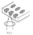
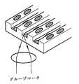
このようなDVD-RAM、DVD-RWディスクは図1に示されたようにディスクの大きさや判読面のトラック層数、複写防止情報などの再生専用データが記録されるリードイン領域10、反復再生及び/または記録可能な使用者データ領域20及びその他のディスクに関連した情報が記録されるリードアウト領域30に分けられる。 Such DVD-RAM and DVD-RW discs, as shown in FIG. 1, have a lead-in
前記使用者データ領域20は図1においてC部を拡大したことを参照すれば、一定のトラックに沿って情報マーク27の記録及び/または再生が行われるようにグルーブ23とランド25とが交互に形成されている。部材番号40は再生ビームを示す。前記リードイン領域10及びリードアウト領域30の一部(A部及びB部)を拡大して見ると物理的な形態のピット15が形成されており、これは再生専用データである。ここで、前記リードアウト領域30は多様な機能を行うが、まず光ピックアップによる記録/再生時に光ピックアップが使用者データ領域を離脱しないようにガードする機能を行う。特に、図2に示されたように第1層L0及び第2層L1の記録層を有する二重層の光記録媒体において前記第1及び第2記録層L0、L1が逆トラック経路を有する場合、第1記録層L0の最外周から第2記録層L1の最外周に層間移動をする時、トラックを離脱せずにトラッキングを保たせる。逆トラック経路は第1記録層L0の内周面から外周面に、続いて第2記録層L1の外周面から内周面に順次にアドレッシングされる場合を意味する。 Referring to the enlarged portion C of the
二重層の場合ROMで第2層の再生方法によってリードアウトの役割をする領域が変わる。逆トラック経路の場合、第1層と第2層の外周部にリードアウト領域の代わりにミドル領域が別に定義される。ところが、記録可能な光記録媒体で単層ディスクの場合には既存のDVD-RAM、RWのようにピット及びグルーブを同時に使用しうる。しかし、二重層の場合、データの記録時、第1層L0の物理的形状によって記録パワーが影響を受ける問題点がある。言い換えれば、第2層L1への記録時、記録光が第1層L0を通過することになるが、この際、ピットのある部分とグルーブのある部分とで透過率に差が生じる。 In the case of a double layer, the area serving as a lead-out varies depending on the reproduction method of the second layer in ROM. In the case of the reverse track path, a middle area is separately defined instead of the lead-out area on the outer periphery of the first layer and the second layer. However, when the recordable optical recording medium is a single-layer disc, pits and grooves can be used simultaneously as in the existing DVD-RAM and RW. However, in the case of a double layer, there is a problem in that the recording power is affected by the physical shape of the first layer L0 during data recording. In other words, when recording on the second layer L1, the recording light passes through the first layer L0. At this time, a difference in transmittance occurs between the pit portion and the groove portion.
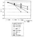
第1層の条件によって透過率差による光パワーがどのように変わるかシミュレーションするために、図3A、図3B、図3C及び図3Dに示されたようにミラー領域、ピット領域、グルーブ領域及びマークが形成されたグルーブ領域のそれぞれに対して測定した。ここで、光パワーの測定時、第1層L0でレンズを通過したレーザービームに捕捉されるトラックの数を考慮した。 In order to simulate how the optical power due to the difference in transmittance changes depending on the conditions of the first layer, as shown in FIGS. 3A, 3B, 3C, and 3D, the mirror area, the pit area, the groove area, and the mark The measurement was made for each of the groove regions in which was formed. Here, when the optical power was measured, the number of tracks captured by the laser beam that passed through the lens in the first layer L0 was considered.
次は入力パラメータ及び実験のための項目を図表化したものである。ここで、Rcは記録層の結晶部分での反射率を、Raは非晶質部分での反射率を各々示す。 The following is a graphical representation of the input parameters and items for the experiment. Here, Rc represents the reflectance at the crystal portion of the recording layer, and Ra represents the reflectance at the amorphous portion.

図4は図3A、図3B、図3C及び図3Dのそれぞれの場合に対して透過率による光パワーを測定した結果を示したグラフである。シミュレーション結果によれば、透過量はミラー基板で最も高く、ピット領域、グルーブ領域及びマークが形成されたグルーブの順に減少する。ピット領域とグルーブ領域ではトラックピッチが狭くなるほど透過された光量が少なくなる。 FIG. 4 is a graph showing the result of measuring the optical power according to the transmittance for each of the cases of FIGS. 3A, 3B, 3C and 3D. According to the simulation result, the amount of transmission is highest in the mirror substrate, and decreases in the order of the pit region, the groove region, and the groove on which the mark is formed. In the pit area and the groove area, the amount of transmitted light decreases as the track pitch decreases.
実験の結果、二重層のディスクの場合、第1層L0の物理的な形態によって透過率が変わるために第2層L1へのデータ記録時に記録パワーに影響を与えるということがわかる。これに第1層の物理的な形態を統一させることが要求され、これによりリードアウト領域またはミドル領域を新たに定義する必要がある。 As a result of the experiment, it is understood that in the case of a double-layer disc, the transmittance varies depending on the physical form of the first layer L0, so that the recording power is affected when data is recorded on the second layer L1. This requires that the physical form of the first layer be unified, and it is necessary to newly define a lead-out area or a middle area.
本発明は前記問題点を解決するために案出されたものであって、記録パワーに影響を与えずに記録及び/または再生時、ピックアップの使用者データ領域からの離脱を防止しうるリードアウト領域を有する光記録媒体を提供することにその目的がある。 The present invention has been devised to solve the above-mentioned problem, and is a readout that can prevent the pickup from leaving the user data area during recording and / or reproduction without affecting the recording power. An object is to provide an optical recording medium having a region.
前記問題点を解決するために本発明に係る光記録媒体は、使用者データ領域及びリードアウト領域を含む光記録媒体であって、
前記光記録媒体の最外周部に所定の記録パターンを記録して、記録及び/または再生時にピックアップが使用者データ領域から外れないようにすることを特徴とする。In order to solve the above problems, an optical recording medium according to the present invention is an optical recording medium including a user data area and a lead-out area,
A predetermined recording pattern is recorded on the outermost peripheral portion of the optical recording medium so that the pickup does not deviate from the user data area during recording and / or reproduction.
本発明に係る光記録媒体は、使用者データ領域とリードアウト領域とをグルーブとして形成し、グルーブの少なくとも一側面にウォッブルを相異なる形に形成することによってピックアップによる再生時、ピックアップの使用者データ領域からの離脱を防止する。また、多層の光記録媒体で第1記録層の全領域が同条件の構造を有させることによって第1記録層での透過率の差による再生及び/または記録の劣化を防止する。 In the optical recording medium according to the present invention, the user data area and the lead-out area are formed as grooves, and wobbles are formed in different shapes on at least one side surface of the groove. Prevent withdrawal from the area. Further, in the multilayer optical recording medium, the entire area of the first recording layer has the structure under the same conditions, thereby preventing reproduction and / or recording deterioration due to the difference in transmittance in the first recording layer.
以下、添付した図面に基づいて本発明を詳しく説明する。
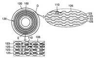
図5を参照すれば、本発明に係る光記録媒体はリードイン領域100、使用者データ領域120及びリードアウト領域130を含み、前記リードイン領域100、使用者データ領域120及びリードアウト領域130はグルーブ123とランド125よりなっており、前記グルーブ123及びランド125の少なくとも一方にはウォッブル105、135が形成されていることを特徴とする。ここで、使用者データ領域120の一部(E部)及びリードアウト領域130の一部(D部)を拡大して示し、部材番号110はレーザービームを示す。Hereinafter, the present invention will be described in detail with reference to the accompanying drawings.
Referring to FIG. 5, an optical recording medium according to the present invention includes a lead-in
前記リードアウト領域130は前述したようにピックアップによるデータ記録及び/または再生時に光ピックアップ(図示せず)の使用者データ領域120からの離脱を防止し、二重層の場合にディスクの最外周で層間ジャンプ時、トラッキングを保たせるガードとしての機能を行う。 As described above, the lead-out
前記ガードとしての機能を行うために本発明に係る第1実施形態は光記録媒体の所定の半径以上の領域では前記使用者データ領域120でのウォッブル105と相違なる形のウォッブルを形成する。すなわち、前記使用者データ領域120とリードアウト領域130でウォッブル105、135の周期、周波数、振幅及び位相のうち少なくとも何れか1つを変調する。例えば、ウォッブル105、135の周波数を変調する場合、前記リードアウト領域130のウォッブル135は使用者データ領域120でのウォッブル105の基本周波数に対してn(nは実数)倍の周波数を有するように形成しうる。一例としてリードアウト領域130でのウォッブル135の周波数を使用者データ領域120の2倍にすることによってガード機能を行わせうる。 In order to perform the function as the guard, the first embodiment according to the present invention forms a wobble different from the
または、ウォッブルの周期Tを変調する場合、例えば使用者データ領域120のウォッブル105には200T、リードアウト領域130のウォッブル135には100Tのウォッブルを記録してリードアウト領域を識別しうる。ここで、ディスクの製造後、前記リードアウト領域に00hパターンを記録しうる。これにより、記録再生時チャンネル1(Ch1)によっては00hパターンを判読し、チャンネル2(Ch2)によってはウォッブル周波数または周期を判読して二重にリードアウト領域130を確認しうる。 Alternatively, when the wobbling period T is modulated, for example, the
一方、第2実施形態によれば光記録媒体を初期化する時、前記リードアウト領域130に所定の記録パターンを記録することによってリードアウト領域を識別可能にする。 On the other hand, according to the second embodiment, when the optical recording medium is initialized, the lead-out area can be identified by recording a predetermined recording pattern in the lead-out
前記所定の記録パターンは前記使用者データ領域120で使われた記録パターンでありうる。言い換えれば、使用者データ領域120で使われた記録パターンのうち所定の記録パターン、例えば、00hパターンを前記リードアウト領域130に反復して記録することによってリードアウト領域を認識する。 The predetermined recording pattern may be a recording pattern used in the
さらに他の方法として、前記使用者データ領域120で使われていない記録パターンをリードアウト領域130に記録することによって前記リードアウト領域130であることを認識させうる。例えば、使用者データ領域120には00hパターンを、リードアウト領域130ではFFhパターンを記録する。ここで、00hやFFhは16進法による記録パターンの一種である。 As another method, a recording pattern not used in the
第3実施形態によれば、光記録媒体は使用者データ領域120及びリードアウト領域130を含み、前記使用者データ領域120及びリードアウト領域130はグルーブ123とランド125よりなっており、前記使用者データ領域120とリードアウト領域130で相異なる形のシンクパターンを使用する。したがって、シンクパターンを認識してリードアウト領域130を識別することによって記録及び/または再生時に光ピックアップの使用者データ領域120からの離脱を防止しうる。 According to the third embodiment, the optical recording medium includes a
ここで、前記リードアウト領域130の幅は(ディスクの最大偏心許容値×2)以上に定め、望ましくは100μm以上にする。 Here, the width of the lead-out
また、本発明にともなう光記録媒体は少なくとも2層以上の記録層を有する多層の光記録媒体において、使用者データ領域120とリードアウト領域130とを含み、前記使用者データ領域120とリードアウト領域130とがグルーブ123及びランド125で形成されていることを特徴とする。 The optical recording medium according to the present invention is a multilayer optical recording medium having at least two recording layers, and includes a
前記グルーブ123及びランド125の少なくとも一方にウォッブル105、135が形成される。前記ウォッブル105、135はアドレッシング情報または基準時間情報を含み、記録及び/または再生時に光ピックアップのデータ領域からの離脱を防止するために前記使用者データ領域120とリードアウト領域130とにあるウォッブル105、135を相異なる形に変調しうる。そして、少なくとも2層以上の記録層を有する多層の光記録媒体で各記録層を区別するために各記録層のリードアウト領域毎に記録パターンを変えて形成する。例えば、二重層の場合、第1層のリードアウト領域には00h、第2層のリードアウト領域にはFFhを記録しうる。このようにすれば、光記録媒体の記録及び/または再生時にチャンネル1(Ch1)によっては記録パターンを判読し、チャンネル2(Ch2)によってはウォッブルの変調方式によるウォッブル信号を判読することによってピックアップのデータ領域からの離脱を防止すると共に各記録層を識別しうる。
一方、層間移動時、トラックを維持可能に前記リードアウト領域130の幅はディスクの最大偏心許容値の2倍以上に定められる。ディスクの製造時、射出によるディスクの偏心が約50μmとすれば、前記リードアウト領域130の幅は100μm以上にする。 On the other hand, the width of the lead-out
さらに他の実施形態として、少なくとも2層以上の記録層を有する多層の光記録媒体において各記録層を区別するために、前記リードアウト領域130でのシンクパターンを各記録層毎に変えて使用しうる。こうして第1層の構造を同じ条件として透過量を均一にしうる。 In another embodiment, the sync pattern in the lead-out
一方、本発明の実施形態に係る光記録媒体は前記グルーブ123及びランド125のうち少なくとも何れか一箇所に記録可能である。 On the other hand, the optical recording medium according to the embodiment of the present invention can be recorded in at least one of the
100 リードイン領域
105、135 ウォッブル
110 レーザービーム
120 使用者データ領域
123 グルーブ
125 ランド
130 リードアウト領域100 Lead-in
Claims (4)
Translated fromJapanese前記使用者データ領域のウォッブルと前記ガード領域のウォッブルの変調方式が相異なり、
前記使用者データ領域は振幅変調方式と位相変調方式を適用したウォッブルを含み、ガード領域は位相変調方式を適用したウォッブルを含むことを特徴とする光記録媒体。Including a user data area and a guard area provided at a position of a predetermined radius or more,
The wobble modulation scheme of the user data area and the guard area wobble are different,
Said user data areaincludes a wobble of applying the amplitude modulation and phase modulation system, the optical recording medium guardregion, characterized in thatit comprises a wobble of applying the phase modulationsystem.
前記光記録媒体に光を照射する段階と、
前記使用者データ領域に記録されたデータを再生する段階を含み、
前記使用者データ領域は第1ウォッブルを備え、前記ガード領域は第2ウォッブルを備え、
前記第1ウォッブルと第2ウォッブルの変調方式が相異なり、
前記第1ウォッブルは振幅変調方式と位相変調方式が適用され、第2ウォッブルは位相変調方式が適用されることを特徴とする方法。In a method of reproducing data from an optical recording medium including a user data area and a guard area provided at a position of a predetermined radius or more,
Irradiating the optical recording medium with light;
Replaying the data recorded in the user data area,
The user data area comprises a first wobble; the guard area comprises a second wobble;
The modulation method of the first wobble and the second wobble is different,
Wherein the firstwobbles are applied amplitude modulation and phase modulation system, the method the second wobble, characterized in thatthe phase modulationscheme is applied.
Applications Claiming Priority (2)
| Application Number | Priority Date | Filing Date | Title |
|---|---|---|---|
| KR20010034377 | 2001-06-18 | ||
| KR2001-034377 | 2001-06-18 |
Related Parent Applications (1)
| Application Number | Title | Priority Date | Filing Date |
|---|---|---|---|
| JP2005072018ADivisionJP2005216482A (en) | 2001-06-18 | 2005-03-14 | Optical recording medium |
Publications (2)
| Publication Number | Publication Date |
|---|---|
| JP2008305542A JP2008305542A (en) | 2008-12-18 |
| JP4964840B2true JP4964840B2 (en) | 2012-07-04 |
Family
ID=19710984
Family Applications (4)
| Application Number | Title | Priority Date | Filing Date |
|---|---|---|---|
| JP2001365201APendingJP2003006877A (en) | 2001-06-18 | 2001-11-29 | Optical recording medium |
| JP2005072018APendingJP2005216482A (en) | 2001-06-18 | 2005-03-14 | Optical recording medium |
| JP2005267433APendingJP2006004629A (en) | 2001-06-18 | 2005-09-14 | Optical recording medium |
| JP2008189003AExpired - LifetimeJP4964840B2 (en) | 2001-06-18 | 2008-07-22 | Optical recording medium |
Family Applications Before (3)
| Application Number | Title | Priority Date | Filing Date |
|---|---|---|---|
| JP2001365201APendingJP2003006877A (en) | 2001-06-18 | 2001-11-29 | Optical recording medium |
| JP2005072018APendingJP2005216482A (en) | 2001-06-18 | 2005-03-14 | Optical recording medium |
| JP2005267433APendingJP2006004629A (en) | 2001-06-18 | 2005-09-14 | Optical recording medium |
Country Status (13)
| Country | Link |
|---|---|
| US (12) | US6772429B2 (en) |
| EP (1) | EP1271491A3 (en) |
| JP (4) | JP2003006877A (en) |
| KR (2) | KR100716963B1 (en) |
| CN (3) | CN1210700C (en) |
| BR (1) | BR0201923A (en) |
| CA (1) | CA2390803C (en) |
| HK (1) | HK1049543B (en) |
| MX (1) | MXPA02005939A (en) |
| MY (2) | MY141854A (en) |
| RU (1) | RU2231831C2 (en) |
| SG (3) | SG143068A1 (en) |
| TW (1) | TW583650B (en) |
Families Citing this family (30)
| Publication number | Priority date | Publication date | Assignee | Title |
|---|---|---|---|---|
| EP1341328A1 (en)* | 1999-06-11 | 2003-09-03 | Matsushita Electric Industrial Co., Ltd. | Data broadcast system, for broadcasting multimedia data; receiving terminal device for receiving said multimedia data |
| TW583650B (en)* | 2001-06-18 | 2004-04-11 | Samsung Electronics Co Ltd | Optical recording medium |
| JP4101666B2 (en)* | 2002-01-22 | 2008-06-18 | 松下電器産業株式会社 | Information recording medium, recording apparatus, reproducing apparatus, recording method, reproducing method |
| US7406022B2 (en)* | 2002-03-15 | 2008-07-29 | Samsung Electronics Co., Ltd. | Optical recording medium |
| KR100911139B1 (en) | 2002-05-30 | 2009-08-06 | 삼성전자주식회사 | Optical disc with a plurality of recording layers, recording method and reproduction method thereof |
| KR100881665B1 (en)* | 2002-05-31 | 2009-02-06 | 삼성전자주식회사 | Multi-layered optical information storage medium and its recording / reproducing method |
| US20050213467A1 (en) | 2002-12-17 | 2005-09-29 | Yoshihiro Noda | Optical recording medium, and recording/reading method and recording/reading apparatus for optical recording medium |
| AU2003289077A1 (en)* | 2002-12-17 | 2004-07-09 | Mitsubishi Chemical Corporation | Optical recording medium, optical recording medium recording/reproduction method, and recording/reproduction device |
| KR100727919B1 (en)* | 2003-02-03 | 2007-06-14 | 삼성전자주식회사 | Optical information storage medium |
| BRPI0408665A (en)* | 2003-03-03 | 2006-03-28 | Matsushita Electric Industrial Co Ltd | information recording method for recording data on an additional recordable information recording medium and information recording and playback apparatus |
| CN100367373C (en)* | 2003-03-24 | 2008-02-06 | 皇家飞利浦电子股份有限公司 | Multilayer optical disc having disc information. |
| DE602004006104T2 (en)* | 2003-03-24 | 2007-12-27 | Koninklijke Philips Electronics N.V. | MULTILAYER OPTICAL PLATE WITH MODULATION OF THE SPURRILLE |
| US20060187807A1 (en)* | 2003-03-24 | 2006-08-24 | Koninklijke Philips Electronics N.V. | Optical disc having focus offset area |
| JP3781027B2 (en)* | 2003-06-27 | 2006-05-31 | ティアック株式会社 | Optical disk device |
| JP3753139B2 (en)* | 2003-06-27 | 2006-03-08 | ティアック株式会社 | Optical disk device |
| KR100936032B1 (en)* | 2003-06-28 | 2010-01-11 | 삼성전자주식회사 | Information storage medium |
| US8339920B2 (en)* | 2003-07-10 | 2012-12-25 | Hewlett-Packard Development Company, L.P. | Optical storage medium with optically detectable marks |
| US7333417B2 (en)* | 2003-09-08 | 2008-02-19 | Samsung Electronics Co., Ltd. | Information storage medium and method and apparatus for recording data on and/or reading data from the same |
| TWI371747B (en)* | 2003-10-13 | 2012-09-01 | Koninkl Philips Electronics Nv | Method and recording apparatus for recording information on a multi-layer disc |
| KR100755421B1 (en)* | 2004-03-03 | 2007-09-04 | 파이오니아 가부시키가이샤 | Information recording device and method |
| KR100667755B1 (en)* | 2004-06-23 | 2007-01-11 | 삼성전자주식회사 | Optical disc having a plurality of recording layers, data recording method and apparatus therefor |
| DE602005017911D1 (en)* | 2004-08-03 | 2010-01-07 | Pioneer Corp | Copying of pre-record flags with dummy data recorded at the time of manufacture in a lead-in management area of a Mt Rainer DVD for fast finalization. |
| KR100667763B1 (en)* | 2004-09-02 | 2007-01-12 | 삼성전자주식회사 | Disk area detection method and apparatus |
| BRPI0509622A (en)* | 2004-09-13 | 2007-09-18 | Lg Electronics Inc | recording medium, method and apparatus for writing data to recording medium |
| RU2009103766A (en) | 2006-12-28 | 2010-08-10 | Панасоник Корпорэйшн (Jp) | METHOD FOR EVALUATING INFORMATION RECORDING MEDIA, INFORMATION RECORDING MEDIA, METHOD FOR PRODUCING INFORMATION RECORDING MEDIA, METHOD FOR SIGNAL PROCESSING AND ACCESS CONTROL DEVICE |
| KR20110008261A (en) | 2008-04-24 | 2011-01-26 | 쓰리엠 이노베이티브 프로퍼티즈 컴파니 | Analysis of Nucleic Acid Amplification Curves Using Wavelet Transform |
| US8209598B1 (en)* | 2009-08-24 | 2012-06-26 | Adobe Systems Incorporated | Exporting electronic documents from rich internet applications |
| KR101983230B1 (en) | 2012-10-19 | 2019-05-29 | 삼성디스플레이 주식회사 | Organic light emitting display device and the manufacturing method thereof |
| JPWO2015163271A1 (en)* | 2014-04-21 | 2017-04-13 | メモリーテック・ホールディングス株式会社 | optical disk |
| KR20220022780A (en) | 2020-08-19 | 2022-02-28 | 삼성전자주식회사 | Semiconductor device |
Family Cites Families (38)
| Publication number | Priority date | Publication date | Assignee | Title |
|---|---|---|---|---|
| US432335A (en)* | 1890-07-15 | Buoyant screw-propeller | ||
| US408009A (en)* | 1889-07-30 | Overseaming sewing-machine | ||
| JP2590835B2 (en)* | 1986-09-30 | 1997-03-12 | ソニー株式会社 | Code modulation method |
| NL8800152A (en) | 1988-01-22 | 1989-08-16 | Philips Nv | OPTICAL READABLE RECORD CARRIER OF THE DESCRIBABLE TYPE, AN APPARATUS FOR MANUFACTURING SUCH RECORD CARRIER, AND ARRANGEMENTS FOR RECORDING AND / OR READING INFORMATION ON / FROM SUCH RECORD CARRIER. |
| JP2869147B2 (en)* | 1990-06-15 | 1999-03-10 | パイオニア株式会社 | Optical information recording medium |
| JPH04332970A (en) | 1991-05-07 | 1992-11-19 | Yamaha Corp | Discoid recording medium |
| JP3163686B2 (en)* | 1991-10-08 | 2001-05-08 | ソニー株式会社 | Playback device |
| JP3476647B2 (en)* | 1996-04-19 | 2003-12-10 | シャープ株式会社 | Optical disk, optical disk manufacturing apparatus and optical disk recording / reproducing apparatus |
| JP2856390B2 (en)* | 1996-07-26 | 1999-02-10 | 株式会社日立製作所 | Information recording medium and recording / reproducing method using the same |
| AU3460497A (en)* | 1996-09-26 | 1998-04-17 | Sanyo Electric Co., Ltd. | Recording medium and its reproducer |
| US6198710B1 (en)* | 1996-10-11 | 2001-03-06 | Sanyo Electric Co., Ltd. | Digital recording method, digital disk, digital disk recording device, and digital disk reproducing device |
| TW357346B (en)* | 1996-10-22 | 1999-05-01 | Hitachi Ltd | Data recording medium and data recording reproduction device by means of oscillation of tracks for showing data |
| JP4143873B2 (en)* | 1997-05-14 | 2008-09-03 | ソニー株式会社 | Optical disc manufacturing method, optical disc and optical disc apparatus |
| WO1998054703A1 (en)* | 1997-05-28 | 1998-12-03 | Sanyo Electric Co., Ltd. | Recording medium and reproducing apparatus therefor |
| JPH1116216A (en)* | 1997-06-19 | 1999-01-22 | Sony Corp | Optical disk and optical disk device |
| US6208614B1 (en) | 1997-08-16 | 2001-03-27 | Lg Electronics Inc. | Information recording medium having same-phase wobbling areas and different-phase wobbling areas |
| JPH11176095A (en)* | 1997-12-05 | 1999-07-02 | Sony Corp | Data recorder and data recording medium |
| US6473377B2 (en)* | 1998-02-26 | 2002-10-29 | Victor Company Of Japan, Ltd. | Optical disc record carrier with wobbled grooves that permit recording on the grooves and lands, apparatus for manufacturing such a record carrier, and recording and/or reproducing apparatus for such a record carrier |
| US6206614B1 (en)* | 1998-04-27 | 2001-03-27 | Deep Oil Technology, Incorporated | Floating offshore drilling/producing structure |
| CN1315037A (en)* | 1998-07-28 | 2001-09-26 | 松下电器产业株式会社 | Optical disc and optical disc drive |
| EP1079376A4 (en)* | 1999-01-29 | 2006-08-02 | Matsushita Electric Industrial Co Ltd | DISC TYPE STORAGE MEDIUM AND TRACKING METHOD USING THE SAME |
| US6847594B1 (en)* | 2000-02-07 | 2005-01-25 | Samsung Electronics Co., Ltd. | Recording medium having wobbled groove tracks out of phase with wobbled land tracks, servo controlling apparatus using wobble signal and method thereof |
| JP2000231722A (en)* | 1999-02-10 | 2000-08-22 | Hitachi Ltd | Optical disc, information recording method and reproducing apparatus therefor |
| JP2000231772A (en) | 1999-02-10 | 2000-08-22 | Fuji Photo Film Co Ltd | Magnetic tape cassette |
| TW468171B (en)* | 1999-06-02 | 2001-12-11 | Koninkl Philips Electronics Nv | Optical record carrier |
| JP4099914B2 (en)* | 1999-12-10 | 2008-06-11 | ソニー株式会社 | Optical disc and optical disc apparatus |
| TW501113B (en)* | 2000-04-25 | 2002-09-01 | Samsung Electronics Co Ltd | Optical disc |
| JP2002260240A (en) | 2000-08-28 | 2002-09-13 | Nikon Corp | Optical information recording medium, stamper, and method of manufacturing stamper |
| TW556173B (en)* | 2000-12-26 | 2003-10-01 | Samsung Electronics Co Ltd | Optical recording medium with wobbled header area, and data recording method and apparatus therefor |
| JP2001210024A (en)* | 2000-12-26 | 2001-08-03 | Sony Corp | Disk-shaped recording medium |
| KR100727916B1 (en)* | 2001-05-02 | 2007-06-13 | 삼성전자주식회사 | Optical disc |
| KR100408282B1 (en)* | 2001-05-16 | 2003-12-03 | 삼성전자주식회사 | Optical recording medium on which wobble signal having header information is recorded, method and apparatus for recording the wobble signal, method and apparatus for reproducing the wobble signal |
| KR100408285B1 (en)* | 2001-05-24 | 2003-12-03 | 삼성전자주식회사 | Optical recording medium on which multi-modulated header signals are recorded, method and apparatus for recording the header signals, method and apparatus for reproducing the header signals |
| TW583650B (en)* | 2001-06-18 | 2004-04-11 | Samsung Electronics Co Ltd | Optical recording medium |
| JP2003168222A (en)* | 2001-09-20 | 2003-06-13 | Victor Co Of Japan Ltd | Information recording carrier, and reproducing method and device for the same |
| KR100716962B1 (en)* | 2001-09-29 | 2007-05-10 | 삼성전자주식회사 | Optical disk |
| JP2003271232A (en)* | 2002-03-12 | 2003-09-26 | Tokyo Electron Ltd | Method and system for collecting data for remote maintenance and diagnosis of production apparatus |
| US7406022B2 (en)* | 2002-03-15 | 2008-07-29 | Samsung Electronics Co., Ltd. | Optical recording medium |
- 2001
- 2001-10-16TWTW090125508Apatent/TW583650B/ennot_activeIP Right Cessation
- 2001-11-20CNCNB011303174Apatent/CN1210700C/ennot_activeExpired - Fee Related
- 2001-11-20CNCNB2005100023610Apatent/CN1311436C/ennot_activeExpired - Fee Related
- 2001-11-20CNCNA2004100628445Apatent/CN1555062A/enactivePending
- 2001-11-29JPJP2001365201Apatent/JP2003006877A/enactivePending
- 2001-12-10USUS10/007,655patent/US6772429B2/ennot_activeExpired - Lifetime
- 2002
- 2002-03-15KRKR1020020014095Apatent/KR100716963B1/ennot_activeExpired - Lifetime
- 2002-05-06MYMYPI20070065Apatent/MY141854A/enunknown
- 2002-05-06MYMYPI20021631Apatent/MY130563A/enunknown
- 2002-05-13SGSG200600355-2Apatent/SG143068A1/enunknown
- 2002-05-13SGSG200600354-5Apatent/SG143067A1/enunknown
- 2002-05-13SGSG200202775Apatent/SG116450A1/enunknown
- 2002-05-23BRBR0201923-0Apatent/BR0201923A/ennot_activeApplication Discontinuation
- 2002-06-12EPEP02254074Apatent/EP1271491A3/ennot_activeWithdrawn
- 2002-06-14MXMXPA02005939Apatent/MXPA02005939A/enactiveIP Right Grant
- 2002-06-17RURU2002116206/28Apatent/RU2231831C2/enactive
- 2002-06-17CACA002390803Apatent/CA2390803C/ennot_activeExpired - Lifetime
- 2003
- 2003-03-04HKHK03101590.9Apatent/HK1049543B/ennot_activeIP Right Cessation
- 2004
- 2004-03-03USUS10/790,702patent/US7000239B2/ennot_activeExpired - Lifetime
- 2004-03-03USUS10/790,861patent/US7274651B2/ennot_activeCeased
- 2005
- 2005-03-09USUS11/074,874patent/US7146624B2/ennot_activeExpired - Lifetime
- 2005-03-14JPJP2005072018Apatent/JP2005216482A/enactivePending
- 2005-09-14JPJP2005267433Apatent/JP2006004629A/enactivePending
- 2006
- 2006-04-21USUS11/408,009patent/US7430160B2/ennot_activeExpired - Lifetime
- 2006-05-12USUS11/432,335patent/US20060203644A1/ennot_activeAbandoned
- 2006-10-27USUS11/588,360patent/US7366084B2/ennot_activeExpired - Lifetime
- 2007
- 2007-02-05KRKR1020070011829Apatent/KR100717068B1/ennot_activeExpired - Lifetime
- 2008
- 2008-02-28USUS12/039,230patent/US20080144482A1/ennot_activeAbandoned
- 2008-02-28USUS12/039,198patent/US20080144481A1/ennot_activeAbandoned
- 2008-02-28USUS12/039,220patent/US7876668B2/ennot_activeCeased
- 2008-07-22JPJP2008189003Apatent/JP4964840B2/ennot_activeExpired - Lifetime
- 2008-09-25USUS12/237,775patent/USRE42162E1/ennot_activeExpired - Lifetime
- 2012
- 2012-03-16USUS13/422,303patent/USRE44168E1/ennot_activeExpired - Fee Related
Also Published As
Similar Documents
| Publication | Publication Date | Title |
|---|---|---|
| JP4964840B2 (en) | Optical recording medium | |
| US20020051414A1 (en) | Multi-layer information recording medium and recording apparatus for the same | |
| US7817529B2 (en) | Optical recording medium | |
| KR20080113115A (en) | Manufacturing Method and Information Recording Reproduction Method of Information Recording Medium | |
| KR100739806B1 (en) | Data reproduction device of optical information storage medium | |
| KR100754229B1 (en) | Data reproduction device of optical information storage medium | |
| KR20040002371A (en) | Information storage medium and method for recording and/or reproducing the same | |
| KR20030092587A (en) | Information storage medium having plural information storage layer |
Legal Events
| Date | Code | Title | Description |
|---|---|---|---|
| A977 | Report on retrieval | Free format text:JAPANESE INTERMEDIATE CODE: A971007 Effective date:20110411 | |
| A131 | Notification of reasons for refusal | Free format text:JAPANESE INTERMEDIATE CODE: A131 Effective date:20110419 | |
| A521 | Request for written amendment filed | Free format text:JAPANESE INTERMEDIATE CODE: A523 Effective date:20110719 | |
| A02 | Decision of refusal | Free format text:JAPANESE INTERMEDIATE CODE: A02 Effective date:20110809 | |
| A521 | Request for written amendment filed | Free format text:JAPANESE INTERMEDIATE CODE: A523 Effective date:20111209 | |
| A911 | Transfer to examiner for re-examination before appeal (zenchi) | Free format text:JAPANESE INTERMEDIATE CODE: A911 Effective date:20120124 | |
| TRDD | Decision of grant or rejection written | ||
| A01 | Written decision to grant a patent or to grant a registration (utility model) | Free format text:JAPANESE INTERMEDIATE CODE: A01 Effective date:20120228 | |
| A01 | Written decision to grant a patent or to grant a registration (utility model) | Free format text:JAPANESE INTERMEDIATE CODE: A01 | |
| A61 | First payment of annual fees (during grant procedure) | Free format text:JAPANESE INTERMEDIATE CODE: A61 Effective date:20120328 | |
| R150 | Certificate of patent or registration of utility model | Ref document number:4964840 Country of ref document:JP Free format text:JAPANESE INTERMEDIATE CODE: R150 Free format text:JAPANESE INTERMEDIATE CODE: R150 | |
| FPAY | Renewal fee payment (event date is renewal date of database) | Free format text:PAYMENT UNTIL: 20150406 Year of fee payment:3 | |
| R250 | Receipt of annual fees | Free format text:JAPANESE INTERMEDIATE CODE: R250 | |
| R250 | Receipt of annual fees | Free format text:JAPANESE INTERMEDIATE CODE: R250 | |
| R250 | Receipt of annual fees | Free format text:JAPANESE INTERMEDIATE CODE: R250 | |
| R250 | Receipt of annual fees | Free format text:JAPANESE INTERMEDIATE CODE: R250 | |
| R250 | Receipt of annual fees | Free format text:JAPANESE INTERMEDIATE CODE: R250 | |
| R250 | Receipt of annual fees | Free format text:JAPANESE INTERMEDIATE CODE: R250 | |
| R250 | Receipt of annual fees | Free format text:JAPANESE INTERMEDIATE CODE: R250 | |
| EXPY | Cancellation because of completion of term |