JP4963006B2 - Wireless sensor system and wheel bearing device with wireless sensor - Google Patents
Wireless sensor system and wheel bearing device with wireless sensorDownload PDFInfo
- Publication number
- JP4963006B2 JP4963006B2JP2003306181AJP2003306181AJP4963006B2JP 4963006 B2JP4963006 B2JP 4963006B2JP 2003306181 AJP2003306181 AJP 2003306181AJP 2003306181 AJP2003306181 AJP 2003306181AJP 4963006 B2JP4963006 B2JP 4963006B2
- Authority
- JP
- Japan
- Prior art keywords
- sensor
- unit
- power
- sensor signal
- wireless
- Prior art date
- Legal status (The legal status is an assumption and is not a legal conclusion. Google has not performed a legal analysis and makes no representation as to the accuracy of the status listed.)
- Expired - Lifetime
Links
- 238000001514detection methodMethods0.000claimsdescription51
- 230000005540biological transmissionEffects0.000claimsdescription34
- 230000008054signal transmissionEffects0.000claimsdescription29
- 238000005096rolling processMethods0.000claimsdescription13
- 230000010287polarizationEffects0.000claimsdescription7
- 230000008859changeEffects0.000claimsdescription3
- 238000012545processingMethods0.000claimsdescription3
- 238000009434installationMethods0.000description5
- 238000012423maintenanceMethods0.000description5
- 238000010248power generationMethods0.000description5
- 238000010586diagramMethods0.000description4
- XLYOFNOQVPJJNP-UHFFFAOYSA-NwaterSubstancesOXLYOFNOQVPJJNP-UHFFFAOYSA-N0.000description4
- 239000013585weight reducing agentSubstances0.000description4
- 238000000926separation methodMethods0.000description3
- 230000008878couplingEffects0.000description2
- 238000010168coupling processMethods0.000description2
- 238000005859coupling reactionMethods0.000description2
- 239000000428dustSubstances0.000description2
- -1foreign matterSubstances0.000description2
- 230000009467reductionEffects0.000description2
- 150000003839saltsChemical class0.000description2
- 238000007789sealingMethods0.000description2
- 239000004065semiconductorSubstances0.000description2
- 239000004575stoneSubstances0.000description2
- 230000005355Hall effectEffects0.000description1
- 239000003990capacitorSubstances0.000description1
- 238000004891communicationMethods0.000description1
- 238000003745diagnosisMethods0.000description1
- 230000000694effectsEffects0.000description1
- 230000007613environmental effectEffects0.000description1
- 230000006872improvementEffects0.000description1
- 238000007726management methodMethods0.000description1
- 238000000034methodMethods0.000description1
- 230000005405multipoleEffects0.000description1
- 230000008569processEffects0.000description1
- 229910052761rare earth metalInorganic materials0.000description1
- 150000002910rare earth metalsChemical class0.000description1
- 239000000725suspensionSubstances0.000description1
- 238000012360testing methodMethods0.000description1
- 238000004148unit processMethods0.000description1
- 229910000859α-FeInorganic materials0.000description1
Images


Classifications
- B—PERFORMING OPERATIONS; TRANSPORTING
- B60—VEHICLES IN GENERAL
- B60C—VEHICLE TYRES; TYRE INFLATION; TYRE CHANGING; CONNECTING VALVES TO INFLATABLE ELASTIC BODIES IN GENERAL; DEVICES OR ARRANGEMENTS RELATED TO TYRES
- B60C23/00—Devices for measuring, signalling, controlling, or distributing tyre pressure or temperature, specially adapted for mounting on vehicles; Arrangement of tyre inflating devices on vehicles, e.g. of pumps or of tanks; Tyre cooling arrangements
- B60C23/02—Signalling devices actuated by tyre pressure
- B60C23/04—Signalling devices actuated by tyre pressure mounted on the wheel or tyre
- B60C23/0408—Signalling devices actuated by tyre pressure mounted on the wheel or tyre transmitting the signals by non-mechanical means from the wheel or tyre to a vehicle body mounted receiver
- B60C23/0418—Sharing hardware components like housing, antenna, receiver or signal transmission line with other vehicle systems like keyless entry or brake control units
- B60C23/042—Sharing hardware components like housing, antenna, receiver or signal transmission line with other vehicle systems like keyless entry or brake control units cooperating with wheel hub mounted speed sensors
- B—PERFORMING OPERATIONS; TRANSPORTING
- B60—VEHICLES IN GENERAL
- B60C—VEHICLE TYRES; TYRE INFLATION; TYRE CHANGING; CONNECTING VALVES TO INFLATABLE ELASTIC BODIES IN GENERAL; DEVICES OR ARRANGEMENTS RELATED TO TYRES
- B60C23/00—Devices for measuring, signalling, controlling, or distributing tyre pressure or temperature, specially adapted for mounting on vehicles; Arrangement of tyre inflating devices on vehicles, e.g. of pumps or of tanks; Tyre cooling arrangements
- B60C23/02—Signalling devices actuated by tyre pressure
- B60C23/04—Signalling devices actuated by tyre pressure mounted on the wheel or tyre
- B60C23/0408—Signalling devices actuated by tyre pressure mounted on the wheel or tyre transmitting the signals by non-mechanical means from the wheel or tyre to a vehicle body mounted receiver
- B60C23/041—Means for supplying power to the signal- transmitting means on the wheel
- B60C23/0413—Wireless charging of active radio frequency circuits
- B—PERFORMING OPERATIONS; TRANSPORTING
- B60—VEHICLES IN GENERAL
- B60C—VEHICLE TYRES; TYRE INFLATION; TYRE CHANGING; CONNECTING VALVES TO INFLATABLE ELASTIC BODIES IN GENERAL; DEVICES OR ARRANGEMENTS RELATED TO TYRES
- B60C23/00—Devices for measuring, signalling, controlling, or distributing tyre pressure or temperature, specially adapted for mounting on vehicles; Arrangement of tyre inflating devices on vehicles, e.g. of pumps or of tanks; Tyre cooling arrangements
- B60C23/02—Signalling devices actuated by tyre pressure
- B60C23/04—Signalling devices actuated by tyre pressure mounted on the wheel or tyre
- B60C23/0408—Signalling devices actuated by tyre pressure mounted on the wheel or tyre transmitting the signals by non-mechanical means from the wheel or tyre to a vehicle body mounted receiver
- B60C23/0418—Sharing hardware components like housing, antenna, receiver or signal transmission line with other vehicle systems like keyless entry or brake control units
- B—PERFORMING OPERATIONS; TRANSPORTING
- B60—VEHICLES IN GENERAL
- B60C—VEHICLE TYRES; TYRE INFLATION; TYRE CHANGING; CONNECTING VALVES TO INFLATABLE ELASTIC BODIES IN GENERAL; DEVICES OR ARRANGEMENTS RELATED TO TYRES
- B60C23/00—Devices for measuring, signalling, controlling, or distributing tyre pressure or temperature, specially adapted for mounting on vehicles; Arrangement of tyre inflating devices on vehicles, e.g. of pumps or of tanks; Tyre cooling arrangements
- B60C23/02—Signalling devices actuated by tyre pressure
- B60C23/04—Signalling devices actuated by tyre pressure mounted on the wheel or tyre
- B60C23/0408—Signalling devices actuated by tyre pressure mounted on the wheel or tyre transmitting the signals by non-mechanical means from the wheel or tyre to a vehicle body mounted receiver
- B60C23/0422—Signalling devices actuated by tyre pressure mounted on the wheel or tyre transmitting the signals by non-mechanical means from the wheel or tyre to a vehicle body mounted receiver characterised by the type of signal transmission means
- B60C23/0433—Radio signals
- B—PERFORMING OPERATIONS; TRANSPORTING
- B60—VEHICLES IN GENERAL
- B60C—VEHICLE TYRES; TYRE INFLATION; TYRE CHANGING; CONNECTING VALVES TO INFLATABLE ELASTIC BODIES IN GENERAL; DEVICES OR ARRANGEMENTS RELATED TO TYRES
- B60C23/00—Devices for measuring, signalling, controlling, or distributing tyre pressure or temperature, specially adapted for mounting on vehicles; Arrangement of tyre inflating devices on vehicles, e.g. of pumps or of tanks; Tyre cooling arrangements
- B60C23/02—Signalling devices actuated by tyre pressure
- B60C23/04—Signalling devices actuated by tyre pressure mounted on the wheel or tyre
- B60C23/0408—Signalling devices actuated by tyre pressure mounted on the wheel or tyre transmitting the signals by non-mechanical means from the wheel or tyre to a vehicle body mounted receiver
- B60C23/0483—Wireless routers between wheel mounted transmitters and chassis mounted receivers
- F—MECHANICAL ENGINEERING; LIGHTING; HEATING; WEAPONS; BLASTING
- F16—ENGINEERING ELEMENTS AND UNITS; GENERAL MEASURES FOR PRODUCING AND MAINTAINING EFFECTIVE FUNCTIONING OF MACHINES OR INSTALLATIONS; THERMAL INSULATION IN GENERAL
- F16C—SHAFTS; FLEXIBLE SHAFTS; ELEMENTS OR CRANKSHAFT MECHANISMS; ROTARY BODIES OTHER THAN GEARING ELEMENTS; BEARINGS
- F16C41/00—Other accessories, e.g. devices integrated in the bearing not relating to the bearing function as such
- F16C41/008—Identification means, e.g. markings, RFID-tags; Data transfer means
- G—PHYSICS
- G01—MEASURING; TESTING
- G01P—MEASURING LINEAR OR ANGULAR SPEED, ACCELERATION, DECELERATION, OR SHOCK; INDICATING PRESENCE, ABSENCE, OR DIRECTION, OF MOVEMENT
- G01P3/00—Measuring linear or angular speed; Measuring differences of linear or angular speeds
- G01P3/42—Devices characterised by the use of electric or magnetic means
- G01P3/44—Devices characterised by the use of electric or magnetic means for measuring angular speed
- G01P3/443—Devices characterised by the use of electric or magnetic means for measuring angular speed mounted in bearings
- G01P3/446—Devices characterised by the use of electric or magnetic means for measuring angular speed mounted in bearings mounted between two axially spaced rows of rolling elements
- F—MECHANICAL ENGINEERING; LIGHTING; HEATING; WEAPONS; BLASTING
- F16—ENGINEERING ELEMENTS AND UNITS; GENERAL MEASURES FOR PRODUCING AND MAINTAINING EFFECTIVE FUNCTIONING OF MACHINES OR INSTALLATIONS; THERMAL INSULATION IN GENERAL
- F16C—SHAFTS; FLEXIBLE SHAFTS; ELEMENTS OR CRANKSHAFT MECHANISMS; ROTARY BODIES OTHER THAN GEARING ELEMENTS; BEARINGS
- F16C19/00—Bearings with rolling contact, for exclusively rotary movement
- F16C19/02—Bearings with rolling contact, for exclusively rotary movement with bearing balls essentially of the same size in one or more circular rows
- F16C19/04—Bearings with rolling contact, for exclusively rotary movement with bearing balls essentially of the same size in one or more circular rows for radial load mainly
- F16C19/06—Bearings with rolling contact, for exclusively rotary movement with bearing balls essentially of the same size in one or more circular rows for radial load mainly with a single row or balls
- F—MECHANICAL ENGINEERING; LIGHTING; HEATING; WEAPONS; BLASTING
- F16—ENGINEERING ELEMENTS AND UNITS; GENERAL MEASURES FOR PRODUCING AND MAINTAINING EFFECTIVE FUNCTIONING OF MACHINES OR INSTALLATIONS; THERMAL INSULATION IN GENERAL
- F16C—SHAFTS; FLEXIBLE SHAFTS; ELEMENTS OR CRANKSHAFT MECHANISMS; ROTARY BODIES OTHER THAN GEARING ELEMENTS; BEARINGS
- F16C19/00—Bearings with rolling contact, for exclusively rotary movement
- F16C19/02—Bearings with rolling contact, for exclusively rotary movement with bearing balls essentially of the same size in one or more circular rows
- F16C19/14—Bearings with rolling contact, for exclusively rotary movement with bearing balls essentially of the same size in one or more circular rows for both radial and axial load
- F16C19/18—Bearings with rolling contact, for exclusively rotary movement with bearing balls essentially of the same size in one or more circular rows for both radial and axial load with two or more rows of balls
- F16C19/181—Bearings with rolling contact, for exclusively rotary movement with bearing balls essentially of the same size in one or more circular rows for both radial and axial load with two or more rows of balls with angular contact
- F16C19/183—Bearings with rolling contact, for exclusively rotary movement with bearing balls essentially of the same size in one or more circular rows for both radial and axial load with two or more rows of balls with angular contact with two rows at opposite angles
- F16C19/184—Bearings with rolling contact, for exclusively rotary movement with bearing balls essentially of the same size in one or more circular rows for both radial and axial load with two or more rows of balls with angular contact with two rows at opposite angles in O-arrangement
- F16C19/186—Bearings with rolling contact, for exclusively rotary movement with bearing balls essentially of the same size in one or more circular rows for both radial and axial load with two or more rows of balls with angular contact with two rows at opposite angles in O-arrangement with three raceways provided integrally on parts other than race rings, e.g. third generation hubs
- F—MECHANICAL ENGINEERING; LIGHTING; HEATING; WEAPONS; BLASTING
- F16—ENGINEERING ELEMENTS AND UNITS; GENERAL MEASURES FOR PRODUCING AND MAINTAINING EFFECTIVE FUNCTIONING OF MACHINES OR INSTALLATIONS; THERMAL INSULATION IN GENERAL
- F16C—SHAFTS; FLEXIBLE SHAFTS; ELEMENTS OR CRANKSHAFT MECHANISMS; ROTARY BODIES OTHER THAN GEARING ELEMENTS; BEARINGS
- F16C2326/00—Articles relating to transporting
- F16C2326/01—Parts of vehicles in general
- F16C2326/02—Wheel hubs or castors
Landscapes
- Engineering & Computer Science (AREA)
- Mechanical Engineering (AREA)
- General Engineering & Computer Science (AREA)
- Physics & Mathematics (AREA)
- General Physics & Mathematics (AREA)
- Computer Networks & Wireless Communication (AREA)
- Arrangements For Transmission Of Measured Signals (AREA)
- Measuring Fluid Pressure (AREA)
Description
Translated fromJapaneseこの発明は、各種の検出信号、例えば自動車におけるタイヤ空気圧や車輪回転数などの検出信号を無線で受信するようにしたワイヤレスセンサシステムおよびワイヤレスセンサ付車輪用軸受装置に関する。The present invention, various detection signals, for example, to a wireless sensorsystem Contact and wheel support bearing assembly equipped wireless sensor so as to receive the detection signal, such as tire pressure and the wheel rotation speed wirelessly in a motor vehicle.
自動車や、各種産業機械等において、種々のセンサを設けることで、軸受や他の各部の回転速度、温度、振動等の各種の検出対象を検出し、機器の制御や状態管理等に用いられている。このようなセンサの出力は、一般的には有線で検出信号を送信するが、適切な配線場所が得難い場合がある。そのような場合に、検出信号を電磁波で送信するようにしたワイヤレスセンサシステムが用いられている。送信機は、小型電池を備えたものとされている。 By providing various sensors in automobiles and various industrial machines, various detection targets such as the rotational speed, temperature, and vibration of bearings and other parts are detected and used for equipment control and state management. Yes. Such a sensor output generally transmits a detection signal by wire, but it may be difficult to obtain an appropriate wiring location. In such a case, a wireless sensor system that transmits a detection signal by electromagnetic waves is used. The transmitter is assumed to have a small battery.
例えば、自動車においては、そのタイヤ空気圧の減少を検出し、パンクの早期検出やタイヤバーストの予知を行うことにより安全性向上を図るために、タイヤ空気圧センサの装着が義務付けられようとしている。一般に、この種の空気圧センサは、その検出信号を電磁波によりワイヤレスで車体に伝送するものがほとんどであり、送信機と小型電池とを一体とした構造とすることで動作電力を確保している。 For example, an automobile is required to be equipped with a tire pressure sensor in order to improve safety by detecting a decrease in tire pressure and detecting a puncture early or predicting a tire burst. In general, most of this type of air pressure sensor wirelessly transmits a detection signal to a vehicle body by electromagnetic waves, and operating power is secured by a structure in which a transmitter and a small battery are integrated.
また、一方で、回転センサにより車輪回転数を検出して車両の制動制御を行うABS(Anti-lock Brake System)では、センサ電線の破損による事故の防止や、組立コストの低減を図るために、回転センサとしてその検出信号を電磁波などとして送信するワイヤレス式のもの(例えば特許文献1)が提案されている。この種の回転センサの代表例では、多極の回転発電機を利用して、自己発電によるセンサ用電力および送信機用電力の供給と回転数検出を同時に行うことで、車体から回転数センサへ電力供給を行うことなく、コンパクトに構成されている(例えば特許文献2)。
上記の電池を電源としたワイヤレスセンサシステムでは、電池に寿命があり、消耗に応じて電池交換の必要があって、電池の寿命管理が煩わしい。電池の処分に伴う環境の問題もある。車輪用軸受装置やタイヤ空気圧の検出に適用する場合は、センサ重量増加によるホイールのアンバランス発生などの問題点も生じる。
上記の自己発電を行う回転センサでは、車輪が回転して初めて発電が行われるため、ABSの動作領域である約10Km/h以上では安定に動作するものの、停止に近い超低速では検出が不安定になる場合がある。また、回転検出以外の検出対象、例えば温度検出等に場合には適用することができない。
このように、ワイヤレスセンサシステムでは、その電源の確保が課題となっている。特に、センサが複数設けられる場合、その各センサやセンサ信号送信部の電源確保が、より一層難しくなっている。In the wireless sensor system using the above battery as a power source, the battery has a life, and it is necessary to replace the battery as the battery is consumed. There are also environmental problems associated with battery disposal. When applied to the detection of a wheel bearing device or tire pressure, problems such as the occurrence of wheel imbalance due to an increase in sensor weight also occur.
In the rotation sensor that performs self-power generation, power generation is performed only after the wheel rotates, so that it operates stably at an ABS operating range of about 10 Km / h or more, but detection is unstable at an ultra-low speed that is close to a stop. It may become. In addition, it cannot be applied to detection objects other than rotation detection, such as temperature detection.
Thus, in the wireless sensor system, securing the power source has become a problem. In particular, when a plurality of sensors are provided, it is even more difficult to secure a power source for each sensor and sensor signal transmission unit.
この発明の目的は、複数のセンサ部に対して動作電力の供給とセンサ信号の送信が可能でありながら、軽量,コンパクトな構成とでき、またメンテナンスが容易で、かつ何時でも通信が可能なワイヤレスセンサシステムを提供することである。
この発明のさらに他の目的は、自動車においてタイヤ空気圧や車輪回転数などの検出結果をワイヤレスのセンサ信号として伝送でき、電池レスによるコスト低減、メンテナンスフリー化、重量低減によるホイールバランスの確保や、また超低速時におけるセンサ動作の可能化等が図れるものとすることである。
この発明のさらに他の目的は、複数のセンサ部に対して動作電力の供給とセンサ信号の送信が可能でありながら、軽量,コンパクトな構成とでき、またメンテナンスが容易で、かつ何時でも通信が可能なワイヤレスセンサ付車輪用軸受装置を提供することである。An object of the present invention is to provide a lightweight and compact configuration while being capable of supplying operating power and transmitting sensor signals to a plurality of sensor units, is easy to maintain, and can be communicated at any time. It is to provide a sensor system.
Still another object ofthis invention, can transmit the detection results, such as tire pressure and the wheel rotational speed as a wireless sensor signal in the automobile, the cost reduction by batteryless, maintenance-free, secure and wheel balance by weight reduction, It is also possible to enable sensor operation at an ultra-low speed.
Still another object of the present invention is to be able to supply operating power and transmit sensor signals to a plurality of sensor units, yet to be light and compact, to be easily maintained, and to communicate at any time.possible is to provide afollower ear-less sensor with wheel bearing apparatus.
この発明ワイヤレスセンサシステムは、検出対象を検出する複数のセンサ部(6A〜6E)と、これらセンサ部(6A〜6E)の出力するセンサ信号をワイヤレスで送信するセンサ信号送信部(9A,9B,9)と、上記センサ部(6A〜6E)およびセンサ信号送信部(9A,9B,9)を駆動する動作電力をワイヤレスで受信する電力受信部(8A,8B,8)と、上記センサ信号送信部(9A,9B,9)で送信されるセンサ信号を受信するセンサ信号受信部(13)と、上記電力受信部(8A,8B,8)へ動作電力をワイヤレスで送信する給電電力送信部(12)とを備えたものである。センサ信号および動作電力のワイヤレスの送受信は、電磁波による他に、磁気結合や、光、超音波等を用いた送受信であっても良く、ワイヤレスで送受信できれば良い。
この構成によると、複数設けられる各センサ部(6A〜6E)、およびセンサ信号送信部(9A,9B,9)は、動作電力がワイヤレスで供給されるので、センサ部(6A〜6E)等の動作電力として電池や発電機をセンサ部(6A〜6E)等に付加する必要がなく、コンパクトで軽量に構成でき、電池交換が不要なためメンテナンスも容易となる。自己発電を行うものと異なり、設置機器の動作状態にかかわらずに何時でも検出および送受信が可能である。The wireless sensor system of the present invention includes a plurality of sensor units (6A to 6E) for detecting a detection target and sensor signal transmission units (9A, 9B, 9B) for wirelessly transmitting sensor signals output from these sensor units (6A to 6E). 9), a power receiving unit (8A, 8B, 8) for wirelessly receiving operating power for driving the sensor units (6A to 6E) and the sensor signal transmitting unit (9A, 9B, 9), and the sensor signal transmission Sensor signal receiving unit (13) for receiving the sensor signal transmitted by the unit (9A, 9B, 9), and a feeding power transmitting unit (for wirelessly transmitting operating power to the power receiving unit (8A, 8B, 8)) 12). The wireless transmission / reception of the sensor signal and the operating power may be transmission / reception using magnetic coupling, light, ultrasonic waves, or the like in addition to electromagnetic waves, as long as wireless transmission / reception is possible.
According to this configuration, each of the plurality of sensor units (6A to 6E) and sensor signal transmission units (9A, 9B, 9) are supplied with operating power wirelessly, so that the sensor units (6A to 6E), etc. It is not necessary to add a battery or a generator as operating power to the sensor unit (6A to 6E), etc., and it can be configured to be compact and lightweight, and maintenance is facilitated because battery replacement is unnecessary. Unlike self-power generation, detection and transmission / reception is possible at any time regardless of the operating state of the installed equipment.
上記構成において、上記センサ信号受信部(13)は、上記センサ信号送信部(9)により送信される複数のセンサ部(6C〜6E)のセンサ信号の受信が可能なものとし、上記給電電力送信部(12)は、上記センサ信号受信部(13)を有するセンサ信号受信機(5)に設けられたものとする。
この構成の場合、複数のセンサ部(6C〜6E)からのセンサ信号の受信と、ワイヤレスの給電電力の送信を共通のセンサ信号受信機(5)から行うものとしたため、ワイヤレスセンサシステムの全体が簡単な構成となる。The said structure WHEREIN: The said sensor signal receiving part (13) shall be able to receive the sensor signal of the several sensor part (6C- 6E) transmitted by the said sensor signal transmission part (9 ), The said electric power transmission The unit (12) is provided in the sensor signal receiver (5 ) having the sensor signal receiving unit (13).
In the case of this configuration, the reception of sensor signals from the plurality of sensor units (6C to 6E) and the transmission of the wireless power supply power are performed from the common sensor signal receiver (5 ). Simple configuration.
実施形態に対応する図8に示すように、上記センサ部(6C〜6E)、センサ信号送信部(9)、および電力受信部(8)を有するワイヤレスセンサユニット(4)を複数設け、これら各ワイヤレスセンサユニット(4)に上記センサ部(6C〜6E)を複数設けると共に、各センサ部のセンサ信号が、上記センサ信号受信部で区別して受信できるようにセンサ信号を処理する信号まとめ手段を設け、上記センサ信号送信部(9)は上記信号まとめ手段で処理されたこれら複数のセンサ部(6C〜6E)のセンサ信号を送信するものとする。
この構成の場合、複数のセンサ部(6C〜6E)のセンサ信号を一つのセンサ信号送信部(9)で送信できるため、構成がより一層簡単で、コンパクト化される。As shown in FIG. 8 corresponding to the embodiment, the sensor unit (6C~6E), the sensor signal transmitter (9), anda plurality set ofRuwa ear-less sensor unit (4) which Yusuke power receiver (8) only, the sensor unit to therespective word ear-less sensor unit (4) a plurality provided with a (6C~6E), the sensor signal of each sensor unit processes the sensor signals can be received by distinguishing in the sensor signal receiving unit A signal summarizing unit is provided, and the sensor signal transmission unit (9) transmits the sensor signals of the plurality of sensor units (6C to 6E) processed by the signal summarizing unit.
In the case of this configuration, since the sensor signals of the plurality of sensor units (6C to 6E) can be transmitted by one sensor signal transmission unit (9), the configuration is further simplified and downsized.
上記各ワイヤレスセンサユニット(4)は、各ワイヤレスセンサユニットの間で互いに同じ給電用周波数の電磁波から同調回路と検波整流回路により動作電力を得る電力受信部(8)と、検出対象の検出を行う複数のセンサ部(6C,6D,6E)と、各センサ部(6C,6D,6E)が検出した信号を上記給電用周波数とは異なる固有周波数の電磁波のセンサ信号として送信するセンサ信号送信部(9)とを有する。上記センサ信号受信機(5)は、上記給電用周波数の電磁波を送信する給電電力送信部(12)と、上記各ワイヤレスセンサユニット(4)の送信する固有周波数のセンサ信号を受信可能なセンサ信号受信部(13)とを有する。
この構成のワイヤレスセンサシステムによると、ワイヤレスセンサユニット(4)は動作電力が無線で供給されるので、センサ動作電力として電池や発電機をセンサに付加する必要がなく、コンパクトで軽量に構成でき、電池交換が不要なためメンテナンスも容易となる。UpperSymbol Each word ear-less sensor unit (4)includes a power receiving unit to obtain the operating power by the tuning circuit and the detection rectifier circuit from the electromagnetic wave ofthe same feed electric frequencieseach other between the respective wireless sensor units (8), to be detected A plurality of sensor units (6C, 6D, 6E) that perform detection, and a sensor signal that transmits a signal detected by each sensor unit (6C, 6D, 6E) as a sensor signal of an electromagnetic wave having a natural frequency different from the power feeding frequency And a transmission unit (9). The sensor signal receiver (5) is feeding power transmitting unit that transmits an electromagnetic wave of the feeding frequency (12), capable of receiving the upperSymbol sensor signals natural frequency of transmission ofeach word ear-less sensor unit (4) And a sensor signal receiver (13).
According to the wireless sensor system of this configuration, since the wireless sensor unit (4) is supplied with operating power wirelessly, there is no need to add a battery or a generator to the sensor as sensor operating power, and it can be configured in a compact and lightweight manner. Maintenance is also easy because no battery replacement is required.
また、上記センサ信号受信機(5)のセンサ信号受信部(13)は、任意に受信周波数を変更できるものであり、時分割で受信周波数を切替えることによって、複数のワイヤレスセンサ信号を受信するものとしても良い。例えば、上記センサ信号受信機(5)のセンサ信号受信部(13)は、ワイヤレスセンサユニット(4)の送信する固有周波数に対応して、同調周波数を可変し得る単一の同調回路と、この同調回路の固有周波数を時分割で切替えて検波する回路としても良い。
この構成の場合、同調周波数の可変手段が必要となるが、受信周波数が多い場合は、同調回路を複数持つ必要がないため、より簡素化・小型化が可能である。The sensor signal receiver (13) of the sensor signal receiver (5 ) can arbitrarily change the reception frequency, and receives a plurality of wireless sensor signals by switching the reception frequency in a time division manner. It is also good. For example, the sensor signal receiving portion of the sensor signal receiver(5)(13), corresponding to the natural frequency of transmitting theword ear-less sensor unit(4), and a single tuning circuit capable of varying the tuning frequency, A circuit for detecting by switching the natural frequency of the tuning circuit in a time division manner may be used.
In this configuration, tuning frequency variable means is required. However, when the reception frequency is high, it is not necessary to have a plurality of tuning circuits, and therefore simplification and miniaturization are possible.
この発明において、給電用電磁波とワイヤレスセンサ信号用電磁波の偏波面を互いに異ならせても良い。給電用電磁波とワイヤレスセンサ信号用電磁波とで異なった周波数を用いることで、送信電力が受信回路に影響を与えないようにされるが、さらに電磁波の偏波面を送信と受信とで変えることにより、送受信回路間の信号分離を向上させることができる。 In the present invention, the polarization planes of the power feeding electromagnetic wave and the wireless sensor signal electromagnetic wave may be different from each other. By using different frequencies for the power supply electromagnetic wave and the wireless sensor signal electromagnetic wave, the transmission power is prevented from affecting the reception circuit, but by further changing the polarization plane of the electromagnetic wave between transmission and reception, Signal separation between the transmission and reception circuits can be improved.
上記複数のセンサ部(6C〜6E)と、上記センサ信号送信部(9)と、上記電力受信部(8)とを軸受に設けても良い。
この構成の場合、例えば、軸受に回転センサ、温度センサ、振動センサ等の複数のセンサ部(6C〜6E)を設置し、これらの信号を共通のセンサ信号送信部(9)で送信することができる。また、電力受信も共通に行え、簡易な構成で済む。The multiple sensor portion(6C~6E), the sensor signal transmission part(9), said power receiving unit (8)may be setonly to thebearing.
In the case of this configuration, for example, a plurality of sensor units (6C to 6E) such as a rotation sensor, a temperature sensor, and a vibration sensor are installed in the bearing, and these signals are transmitted by the common sensor signal transmission unit (9). it can. Moreover, power reception can be performed in common, and a simple configuration is sufficient.
この発明の上記ワイヤレスセンサシステムにおいて、軸受に設けられるセンサ部(6C〜6E)の少なくとも一つが回転センサであり、この回転センサが、円周方向に多数の磁極を有する多極磁石(17)とその磁極を検出する磁気センサ(18)とでなるものであっても良い。この磁気センサ(18)は磁気抵抗型センサであることが好ましい。
回転センサが、多極磁石(17)と磁気センサ(18)との組み合わせであると、小型で分解能等の精度の良い回転センサが構成できる。また、磁気抵抗型の磁気センサ(18)は電力消費量が少ないため、配線に比べて給電効率の悪いワイヤレス給電に組み合わせるセンサとして好ましい。Oitetheverge Iyaresusensupport system on the present invention, at least one rotation sensor of the sensor unit provided in the bearing(6C ~6E), the rotation sensor, multi-pole magnet having a plurality of magnetic poles in the circumferential direction (17) and a magnetic sensor (18) for detecting the magnetic pole may be used. The magnetic sensor (18) is preferably a magnetoresistive sensor.
When the rotation sensor is a combination of the multipolar magnet (17) and the magnetic sensor (18), a rotation sensor having a small size and high accuracy such as resolution can be configured. In addition, since the magnetoresistive magnetic sensor (18) consumes less power, it is preferable as a sensor combined with wireless power feeding that has lower power feeding efficiency than wiring.
また、この発明の上記いずれかの構成のワイヤレスセンサシステムにおいて、センサ部(6C〜6E)が、軸受における外部から遮断された密閉空間内にあり、電力受信部(8)およびセンサ信号送信部(9)が軸受の外部にあっても良い。上記密封空間は、例えば転がり軸受における内輪と外輪との間における両側のシールで密封された軸受内空間であり、車輪用軸受である場合、その内方部材(2)と外方部材(1)間の空間である。
センサ部(6C〜6E)が軸受における外部から遮断された密閉空間内にあると、外部の塵埃、異物、水等から守られるので、センサ部(6C〜6E)の信頼性と耐久性が向上する。特に、軸受装置が車輪用軸受装置(33)である場合は、軸受が路面に面して異物や塩泥水を被り易い環境下にあるため、密閉空間内に設けられることによる信頼性,耐久性の向上がより効果的となる。電力受信部(8)およびセンサ信号送信部(9)は、軸受の外部にある方が、ワイヤレスによる送受の面で好ましい。Further, Oitewireless sensor system of the one arrangement of the invention, the sensor unit(6C ~6E) is in the sealed space that is cut off from the outside of the bearing, the power receiving section(8) and sensor signals The transmitter (9 ) may be outside the bearing. The sealed space is, for example, a bearing inner space sealed with seals on both sides between an inner ring and an outer ring in a rolling bearing, and in the case of a wheel bearing, its inner member (2) and outer member (1). It is a space between.
When the sensor unit (6C- 6E) is in a sealed space that is blocked from the outside of the bearing, it is protected from external dust, foreign matter, water, etc., so the reliability and durability of the sensor unit (6C- 6E) is improved. To do. In particular, when the bearing device is a wheel bearing device (33), since the bearing faces the road surface and is easily exposed to foreign matter and salt mud water, reliability and durability due to being provided in a sealed space. Is more effective. The power receiver (8 ) and the sensor signal transmitter (9 ) are preferably located outside the bearing in terms of wireless transmission / reception.
この発明のワイヤレスセンサシステムにおいて、センサ部(6C〜6E)の一つが車輪用軸受に設けられる場合、例えばこの発明の上記いずれかの構成のワイヤレスセンサ付車輪用軸受装置(33)と、このワイヤレスセンサ付車輪用軸受装置(33)における上記センサ信号送信部(9)から送信されるセンサ信号を受信するセンサ信号受信部(13)、および上記電力受信部(8)へ動作電力をワイヤレスで送信する給電電力送信部(12)とを備える場合に、これらセンサ信号受信部(13)および給電電力送信部(12)を、車輪用軸受装置(33)の設置された車体(34)のタイヤハウス(34a)、またはタイヤハウス(34a)よりも車輪用軸受装置(33)から離れた車体部分に配置しても良い。タイヤハウス(34a)よりも車輪用軸受装置(33)から離れた車体部分は、例えばコンソール部など、自動車における車両全体の電気的制御を行う装置(ECU等)が設置された箇所であっても良い。
タイヤハウス(34a)よりも車輪用軸受装置(33)から離れた車体部分にセンサ信号受信部(13)および給電電力送信部配置(12)することで、タイヤハウス(34a)と車輪用軸受装置(33)間のハーネスを無くすことができて、飛び石によるハーネスの断線による故障が回避でき、また軽量化が図れる。タイヤハウス(34a)にセンサ信号受信部(13)および給電電力送信部(12)を設けた場合は、ワイヤレス送受の距離が短くて済むため、電波強度を弱くくでき、また消費電力が少なくて済む。In the wireless sensor system of the present invention, when one of the sensor units (6C to 6E) is provided in the wheel bearing, for example, the wireless sensor-equipped wheel bearing device (33) having any one of the above configurations of the present invention and the wireless sensor system The sensor signal receiver (13) that receives the sensor signal transmitted from the sensor signal transmitter (9 ) in the wheel bearing device with sensor (33), and the operating power is wirelessly transmitted to the power receiver (8 ). When the power supply power transmission unit (12) is provided, the sensor signal reception unit (13) and the power supply power transmission unit (12) are connected to the tire house of the vehicle body (34) where the wheel bearing device (33) is installed. (34a), or may be disposed in a vehicle body portion that is further away from the wheel bearing device (33) than the tire house (34a). Even if the vehicle body part further away from the wheel bearing device (33) than the tire house (34a) is a place where a device (ECU or the like) that performs electrical control of the entire vehicle in the automobile, such as a console unit, is installed. good.
The tire house (34a) and the wheel bearing device are arranged by disposing the sensor signal receiving unit (13) and the feeding power transmitting unit (12) in the vehicle body part farther from the wheel bearing device (33) than the tire house (34a). The harness between (33) can be eliminated, failure due to disconnection of the harness due to stepping stones can be avoided, and weight reduction can be achieved. When the sensor signal receiving unit (13) and the feeding power transmitting unit (12) are provided in the tire house (34a), the wireless transmission / reception distance can be shortened, so that the radio wave intensity can be weakened and the power consumption is small. That's it.
この発明のワイヤレスセンサシステムは、検出対象を検出する複数のセンサ部と、これらセンサ部の出力するセンサ信号をワイヤレスで送信するセンサ信号送信部と、上記センサ部およびセンサ信号送信部を駆動する動作電力をワイヤレスで受信する電力受信部と、上記センサ信号送信部で送信されるセンサ信号を受信するセンサ信号受信部と、上記電力受信部へ動作電力をワイヤレスで送信する給電電力送信部とを備え、上記センサ信号受信部は、上記センサ信号送信部により送信される複数のセンサ部のセンサ信号の受信が可能なものであり、上記給電電力送信部は、上記センサ信号受信部を有するセンサ信号受信機に設けられたものであり、上記センサ部、センサ信号送信部、および電力受信部を有する一つのワイヤレスセンサユニットを設け、このワイヤレスセンサユニットに、上記センサ部を複数設けると共に、各センサ部のセンサ信号が、上記センサ信号受信部で区別して受信できるようにセンサ信号を処理する信号まとめ手段を設け、上記センサ信号送信部は上記信号まとめ手段で処理されたこれら複数のセンサ部のセンサ信号を送信するものとしたものであるため、複数のセンサ部に対して動作電力の供給とセンサ信号の送信が可能でありながら、軽量,コンパクトな構成とでき、またメンテナンスが容易で、かつ何時でも通信が可能なテステムとできる。
上記ワイヤレスセンサユニットを自動車のタイヤ空気圧センサに用いる場合は、電池レスによるコスト低減、メンテナンスフリー、重量低減によるホイールバランスの向上が可能になる。また、上記ワイヤレスセンサユニットを自動車の車輪用軸受装置の回転センサに用いる場合は、停止時にも電力供給ができることから、ほぼ停止している状態での回転検出が可能で、低摩擦係数路での停止寸前のABS作動や、発進時,超低速時のトラクション制御など、より高度な制御による走行安定性を実現することができる。The wireless sensor system of the present invention includes a plurality of sensor units that detect a detection target, a sensor signal transmission unit that wirelessly transmits a sensor signal output from these sensor units, and an operation that drives the sensor unit and the sensor signal transmission unit. A power receiving unit that wirelessly receives power; a sensor signal receiving unit that receives a sensor signal transmitted by the sensor signal transmitting unit; and a feed power transmitting unit that wirelessly transmits operating power to the power receiving unit.The sensor signal receiving unit is capable of receiving sensor signals from a plurality of sensor units transmitted by the sensor signal transmitting unit, and the feeding power transmitting unit is a sensor signal having the sensor signal receiving unit. A wireless sensor unit is provided in the receiver and includes the sensor unit, the sensor signal transmission unit, and the power reception unit. The wireless sensor unit is provided with a plurality of the sensor units, and is provided with signal summarizing means for processing the sensor signals so that the sensor signals of each sensor unit can be distinguished and received by the sensor signal receiving unit. Since the signal transmission unit is to transmit the sensor signals of the plurality of sensor units processed by the signal summarizing means, it is possible to supply operating power and transmit sensor signals to the plurality of sensor units. Nevertheless, it can be a lightweight, compact configuration, easy maintenance, and a test system that can communicate at any time.
When using theupper Symbol wireless sensor units in the tire air pressure sensor of a motor vehicle, cost reduction by batteryless, maintenance-free, it is possible to improve wheel balance by weight reduction. In addition, when the wireless sensor unit is used as a rotation sensor for a vehicle wheel bearing device, power can be supplied even when the vehicle is stopped. It is possible to realize traveling stability by more advanced control such as ABS operation just before stopping, traction control at the time of starting, or at ultra-low speed.
この発明のワイヤレスセンサ付軸受装置およびワイヤレスセンサ付車輪用軸受装置は、複数のセンサ部に対して動作電力の供給とセンサ信号の送信が可能でありながら、軽量,コンパクトな構成とでき、またメンテナンスが容易で、かつ軸受動作状態にかかわらずに何時でも通信が可能なものとなる。 The bearing device with a wireless sensor and the wheel bearing device with a wireless sensor according to the present invention can be configured to be lightweight and compact, and can be maintained while being able to supply operating power and transmit sensor signals to a plurality of sensor units. Therefore, communication is possible at any time regardless of the bearing operating state.
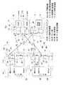
第1の参考提案例を図面と共に説明する。図1に示すように、このワイヤレスセンサシステムは、複数のワイヤレスセンサユニット4A,4Bと、これら複数のワイヤレスセンサユニット4A,4Bに対してワイヤレスで電力を供給しかつ各センサ信号を受信するセンサ信号受信機5とを備える。ワイヤレスセンサユニットの個数は特に制限がないが、図1は2個の場合を示している。A firstreference proposal example will be described withreference to the drawings. As shown in FIG. 1, this wireless sensor system includes a plurality of
各ワイヤレスセンサユニット4A,4Bは、それぞれセンサ部6A,6Bと、送受信部7A,7Bとからなる。センサ部6A,6Bは、検出対象の検出を行う手段である。送受信部7A,7Bは、それぞれ電力受信部8A,8Bと、センサ信号送信部9A,9Bとでなる。 Each of the
図2に示すように、電力受信部8A,8Bは、所定の給電用周波数f1の電磁波から、同調回路10A,10Bと検波整流回路11A,11Bにより動作電力を得る手段である。得られた動作電力は、センサ部6A,6Bとセンサ信号送信部9A,9Bの駆動に用いられる。電力受信部8A,8Bは、アンテナ22、LC回路23等からなる同調回路10Aと、ダイオード24、コンデンサ25等からなる検波整流回路11Aとで構成される。
センサ信号送信部9A,9Bは、センサ部6A,6Bが検出した信号を給電用周波数f1とは異なる固有周波数f2,f3の電磁波のセンサ信号としてそれぞれ送信する手段である。センサ信号送信部9A,9Bは、アンテナ19、LC回路20、半導体スイッチング素子21などからなる。As shown in FIG. 2, the
The sensor
センサ信号受信機5は、上記給電用周波数f1の電磁波を送信する給電電力送信部12と、上記複数のワイヤレスセンサユニット4A,4Bの送信する各固有周波数f2,f3のワイヤレスセンサ信号を受信可能なセンサ信号受信部13とを有する。給電電力送信部12は、高周波発信部26と送信部27とでなり、送信部27は、アンテナ28、LC回路29、半導体スイッチング素子30などからなる。センサ信号受信部13は、上記各ワイヤレスセンサユニット4A,4Bに対応する複数(図示の例では2つ)の受信回路13aからなる。各受信回路13aは各ワイヤレスセンサユニット4A,4Bの送信する固有周波数f2,f3にそれぞれ対応した単一周波数の受信回路であって、それぞれ同調回路37と検波部38とを有する。同調回路37は、アンテナ39、LC回路40などからなる。 The
センサ信号受信機5から送信される給電用電磁波の偏波面と、各ワイヤレスセンサユニット4A,4Bから送信されるセンサ信号用電磁波の偏波面とは互いに異ならせてある。周波数の違いに加えて、偏波面を互いに異ならせることで、給電用電磁波のセンサ信号用電磁波への影響がより確実に回避され、信号分離が向上する。また、各ワイヤレスセンサユニット4A,4Bから送信されるセンサ信号用電磁波の偏波面同士も互いに異ならせてある。これにより各ワイヤレスセンサユニット4A,4Bから送信されるセンサ信号用電磁波の混信回避,信号分離の向上が得られる。 The plane of polarization of the power feeding electromagnetic wave transmitted from the
この構成のワイヤレスセンサシステムによると、各ワイヤレスセンサユニット4A,4Bは動作電力がワイヤレスで供給されるので、センサ動作電力として電池や発電機をセンサに付加する必要がなく、コンパクトで軽量に構成できる。電池交換が不要なためメンテナンスも容易となる。また、複数のワイヤレスセンサユニット4A,4Bに対して共通のセンサ信号受信機5からワイヤレスの電力供給とワイヤレスセンサ信号の受信とを行うようにしたため、ワイヤレスセンサシステムの全体が簡素な構成となる。 According to the wireless sensor system having this configuration, each
図3は他の参考提案例におけるセンサ信号受信機5Aの構成を示す。この参考提案例は、図2に示した第1の参考提案例において、センサ信号受信機5Aを同図の構成としたものである。ワイヤレスセンサユニットには第1の参考提案例と同じものが用いられる。この例では、センサ信号受信機5Aにおけるセンサ信号受信部13Aが、各ワイヤレスセンサユニット4A,4B(図2)の送信する固有周波数f2,f3にそれぞれ対応した単一周波数の複数の同調回路37A,37Bと、これら複数の同調回路37A,37Bの出力を時分割で切替えて検波する1つの切替え検波部41とで構成されている。切替え検波部41は、検波部42と、両同調回路37A,37Bを時分割で切替えて検波部42に接続する切替部43とでなる。その他の構成は第1の参考提案例におけるセンサ信号受信機5と同じである。FIG. 3 shows a configuration of a
この参考提案例の場合、切替え検波部41の切替部43が同調回路37Aを検波部42に切替え接続したときに、その同調回路37Aが受信する回転数検出用のワイヤレスセンサユニット4Aからの周波数f2の信号を検波部42が検波する。切替え検波部41の切替部43が同調回路37Bを検波部42に切替え接続したときは、その同調回路37Bが受信するワイヤレスセンサユニット4Bからの周波数f3の信号を検波部42が検波する。
この参考提案例の場合、複数(ここでは2つ)のワイヤレスセンサユニット4A,4Bから送信される固有周波数f2,f3の電磁波を、センサ信号受信機5Aでは1つの検波部42により区別して検波できるので、ワイヤレスセンサユニットの数が多い場合でもセンサ信号受信機5Aの構成を簡略化できる。In the case of thisreference proposal example , when the switching
In the case of thisreference proposal example , the electromagnetic waves having the natural frequencies f2 and f3 transmitted from a plurality (two in this case) of the
なお、図3の参考提案例において、複数の同調回路37A,37Bを設ける代わりに、各ワイヤレスセンサユニット4A,4B(図2)の送信する固有周波数に対応して、同調周波数を可変し得る単一の同調回路を設けても良い。その場合、センサ信号受信部13Aは、この可変の同調回路の固有周波数を切替部により時分割で切替えて、検波部42で検波する回路とする。In thereference proposal example of FIG. 3, instead of providing a plurality of
つぎに、この参考提案例のワイヤレスセンサシステムを自動車に適用した例を、図4,図5と共に説明する。この参考提案例は、車輪31の回転数とタイヤ空気圧を検出するものである。図4に示すように、車輪31は、車輪用軸受装置33を介して車体34に回転自在に支持されている。車輪用軸受装置33は、車輪支持部材となる外方部材1と、回転部材となる内方部材2との間に複列の転動体3を介在させたものである。外方部材1は、車体34から下方に突出したサスペンションに、ナックル(図示せず)を介して支持されている。内方部材2は、一端の外周に車輪取付フランジ2aを有するハブ輪2Aと等速ジョイント15の外輪15aを組み合わせたものとされ、ハブ輪2Aの車輪取付フランジ2aに車輪31が取付けられている。車輪31の車輪用軸受装置33の内方部材2は、等速ジョイント15を介して車軸16に連結されている。Next, anexample in which the wireless sensor system of thisreference proposal example is applied to an automobile will be described with reference to FIGS. Thisreference proposal example detects the rotation speed of the
外方部材1と内方の内方部材2の環状空間の一端部には、車輪31の回転数を検出するためのワイヤレスセンサユニット4Aが設置されている。また、車輪31には、そのタイヤ空気圧を検出するためのワイヤレスセンサユニット4Bが設置されている。車体34の例えばタイヤハウス34aには、前記各ワイヤレスセンサユニット4A,4Bに対してワイヤレスで電力を供給し、かつ各ワイヤレスセンサユニット4A,4Bからのセンサ信号を受信するセンサ信号受信機5が設置されている。各ワイヤレスセンサユニット4A,4Bは、図2と共に前述した構成のものである。センサ信号受信機5は、図2と共に説明したもの、または図3と共に説明したものである。 A
回転数検出用のワイヤレスセンサユニット4Aのセンサ部6A、つまり回転センサとなるセンサ部6Aは、図4のように内方部材2に装着された磁気エンコーダ17と、この磁気エンコーダ17に対峙して外方部材1に装着される磁気センサ18とで構成される。磁気エンコーダ17は、円周方向に並べて磁極N,Sを設けた多極磁石からなる。磁石にはフェライト系、希土類系のゴム磁石、プラスチック磁石、焼結磁石を使用しても良い。磁気センサ18は、磁気抵抗型センサ、つまり磁気抵抗素子(「MR素子」とも呼ばれる)を用いたセンサからなり、車輪31の回転に伴う磁気エンコーダ17の磁極変化を検出してインクリメンタルなパルス信号をセンサ信号として出力する。磁気センサ18は、磁気抵抗型センサの他にホール効果型センサや、MIセンサ、フラックスゲート型磁界センサ等であっても良い。回転センサは、多極磁石と磁気センサとの組み合わせであると、小型で分解能等の精度の良い回転センサが構成できる。また、磁気抵抗型の磁気センサはセンサ素子の抵抗値を大きくすることで消費電電力を小さくできるので、配線に比べて給電効率の悪いワイヤレス給電に組み合わせるセンサとして好ましい。
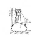
タイヤ空気圧検出用のワイヤレスセンサユニット4Bは、例えば図5に示すようにタイヤホイール35の一部に装着される。タイヤ空気圧検出用のワイヤレスセンサユニット4Bにおけるセンサ部6B(図1)は、タイヤ36の空気圧を検出するセンサである。The
The
動作を説明する。車体34に設置されたセンサ信号受信機5の給電電力送信部12(図1)から送信される給電用電磁波は、回転数検出用のワイヤレスセンサユニット4Aおよびタイヤ空気圧検出用のワイヤレスセンサユニット4Bの各電力受信部8A,8Bで受信され検波整流されることで、各ワイヤレスセンサユニット4A,4Bに動作電力が得られる。 The operation will be described. The power supply electromagnetic wave transmitted from the power supply transmission unit 12 (FIG. 1) of the
車輪用軸受装置33に設置された回転数検出用のワイヤレスセンサユニット4Aでは、そのセンサ部6Aによって車輪の回転数が検出される。すなわち、車輪31の回転に伴う内方部材2側の磁気エンコーダ17の磁極変化を、外方部材1側のホイール回転センサの磁気センサ18が検出し、インクリメンタルな検出信号を出力する。この検出信号は、センサ信号送信部9Aによって周波数f2の電磁波を搬送波としてワイヤレス送信される。この電磁波は、センサ信号受信機5のセンサ信号受信部13における2つの受信回路のうち、ワイヤレスセンサユニット4Aに対応する受信回路で受信・検波されて、車輪回転数に関するセンサ信号として出力される。 In the
また、車輪31のタイヤホイール35に設置されたタイヤ空気圧検出用のワイヤレスセンサユニット4Bでは、そのセンサ部6Bによってタイヤ空気圧が検出される。その検出信号は、センサ信号送信部9Bによって周波数f3の電磁波を搬送波としてワイヤレス送信される。この電磁波は、センサ信号受信機5のセンサ信号受信部13における2つの受信回路のうち、ワイヤレスセンサユニット4Bに対応する受信回路で受信・検波されて、タイヤ空気圧に関するセンサ信号として出力される。 In the
このように、このワイヤレスセンサシステムでは、車体34に設置されるセンサ信号受信機5から各ワイヤレスセンサユニット4A,4Bに対して電磁波として電力をワイヤレスで供給すると共に、各ワイヤレスセンサユニット4A,4Bから電磁波として送信されるセンサ信号を受信するようにしているので、電池をセンサの電源とする従来例のような電池切れ等の問題がない。また、検出されるタイヤ空気圧や車輪回転数などの検出結果をワイヤレス信号として確実に伝送でき、かつ各ワイヤレスセンサユニット4A,4Bにおけるセンサ部6A,6Bをコンパクトで安価に構成できる。電池交換が不要なためメンテナンスも容易となる。 As described above, in this wireless sensor system, electric power is supplied wirelessly as electromagnetic waves from the
磁気センサ18をセンサ部6Aとして持つ回転数検出用のワイヤレスセンサユニット4Aの場合、車輪31の回転により動作電力を発電する自己発電型のものでないので、停止に近い車輪回転時でも回転数検出を確実に行うことができ、低摩擦係数路での停止寸前のABS作動や発進時・超低速時のトラクション制御など、より高度な制御による走行安定性を実現できる。
また、タイヤ空気圧センサをセンサ部6Bとして持つワイヤレスセンサユニット4Bの場合、動作電力のための電池がないことから、重量低減によるホイールバランスを確保することができる。In the case of the
Further, in the case of the
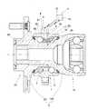
なお、図4に示す車輪用軸受装置33は、第4世代型のものであるが、この発明は、各世代型の車輪用軸受装置に適用でき、例えば図6に示す第3世代型の車輪用軸受装置に適用することができる。同図の例では、内方部材2は、ハブ輪2Aとその一端の外周に嵌合した内輪2Bとでなり、ハブ輪2Aおよび内輪2Bに、各列の軌道面が形成される。両軌道面に対向する軌道面は、図4に示す例と同様に、外方部材1の内周に設けられる。ハブ輪2Aには、等速ジョイント15の外輪15aに設けられた軸部が嵌合し、内方部材2と等速ジョント外輪15aとが結合される。
回転数検出用のワイヤレスセンサユニット4Aのセンサ部(回転センサ)6Aは、内方部材2に装着された磁気エンコーダ17と、この磁気エンコーダ17に対峙して外方部材1に装着される磁気センサ18とで構成される。磁気エンコーダ17は、内方部材2に装着されたシール構成部品となるスリンガに設けられている。同図の例におけるその他の構成は、図4,図5に示した参考提案例と同様である。The
The sensor unit (rotation sensor) 6A of the
なお、図4,図6等に示す車輪用軸受装置33において、複数のワイヤレスセンサユニット4A,4Bを、例えば図6に一点鎖線で示すように、車輪用軸受装置33の外方部材1に設けても良い。その場合に、一つのワイヤレスセンサユニット4Aは、例えば回転センサをセンサ部6Aとするものとし、他の一つのワイヤレスセンサユニット4Bは、温度センサまたは振動センサをセンサ部6Bとしても良い。 In the
図7は、さらに他の参考提案例を示す。この参考提案例は、複数の転がり軸受51,52を有する機械設備53において、上記複数の転がり軸受51,52の各々に、図1,図2に示す参考提案例におけるワイヤレスセンサユニット4A,4Bを設置したものである。機械設備53は、例えばローラコンベヤまたはベルトコンベア等のコンベアラインであって、搬送ローラまたはベルト駆動ローラ等の軸となる回転軸59が、上記転がり軸受51,52によって回転自在に支持されている。各転がり軸受51,52は、内輪54,外輪55の間に転動体56を介在させ、シール58を設けたものであり、深溝玉軸受等からなる。各転動体56は保持器57により保持されている。Figure7 is showing the otherreferences proposed examples et. In thisreference proposal example , in the
一つの転がり軸受51に設置されたワイヤレスセンサユニット4Aは、回転検出用のものであり、センサ部6Aが、内軸54に装着された磁気エンコーダ17と、この磁気エンコーダ17に対峙して外輪55に装着された磁気センサ18とで構成される。他の転がり軸受52に設置されたワイヤレスセンサユニット4Bは、センサ部6Bが、軸受52における回転の他の検出対象、例えば温度または振動等を検出するセンサとされている。 The
センサ信号受信機5は、機械設備53において、両軸受51,52に設置された各ワイヤレスセンサユニット4A,4Bに対してセンサ信号の受信および動作電力の送信が可能な適宜の位置に設置される。この参考提案例において、特に説明した事項を除き、図1,図2に示した参考提案例と同じ構成である。The
この構成の場合、機械設備53における複数の転がり軸受51,52においてワイヤレスセンサユニット4A,4Bにより検出したセンサ信号が、共通のセンサ信号受信機5によって受信でき、また両ワイヤレスセンサユニット4A,4Bに共通のセンサ信号受信機5から電力供給することができる。
同図の参考提案例は、ワイヤレスセンサユニット4A,4Bが2個である場合につき説明したが、機械設備53における3個以上の転がり軸受にワイヤレスセンサユニットを設置し、共通のセンサ信号受信機5によりセンサ信号の受信、およびワイヤレス給電を行うようにしても良い。In the case of this configuration, the sensor signals detected by the
The example of thereference proposal in the figure has been described for the case where there are two
図8は、この発明の実施形態を示す。この実施形態に係るワイヤレスセンサシステムは、ワイヤレスセンサユニット4を複数とし、これら各ワイヤレスセンサユニット4に複数のセンサ部6C〜6Eを設けたものである。各ワイヤレスセンサユニット4は、上記複数のセンサ部6C〜6Eと、センサ信号送信部7と、電力受信部9とをそれぞれ有する。センサ信号送信部9は、上記複数のセンサ部6C〜6Eのセンサ信号を送信するものとしてある。複数のセンサ部6C〜6Eの出力は、信号まとめ手段60により、センサ信号送信部9により送信可能なように処理される。信号まとめ手段60は、各センサ部6C〜6Eのセンサ信号が、受信側で区別して受信できるように信号を処理するものであれば良く、例えば、各センサ部6C〜6Eのセンサ信号を時分割してセンサ信号送信部9に送信させるものとされる。信号まとめ手段60は各センサ部6C〜6Eのセンサ信号を重畳するものであっても良い。電力受信部8は、受信した電力を、各センサ部6C〜6E、センサ信号送信部7、および信号まとめ手段60に給電する。センサ信号送信部9、電力受信部8、および信号まとめ手段60により、送信ユニット7が構成される。なお、信号まとめ手段60は、センサ信号送信部9の一部として設けられたものであっても、またセンサ信号送信部9とは別に設けられたものであっても良い。FIG. 8 shows an embodiment of the present invention. Wireless sensor system according to this embodiment,the
センサ信号受信機5は、ワイヤレスセンサユニット4のセンサ信号送信部7から送信されるセンサ信号を受信するセンサ信号受信部13と、ワイヤレスセンサユニット4の電力受信部8へ電力をワイヤレスで供給する給電電力送信部12とを有する。センサ信号受信部13は、ワイヤレスセンサユニット4のセンサ信号送信部9より送信される各センサ部6C〜6Eのセンサ信号を、信号まとめ手段60の処理形態に対応して、区別して受信可能なものとされる。センサ信号送信部9とセンサ信号受信部13との間、および給電電力送信部12と電力受信部8との間の信号または電力の送受は、ワイヤレスで行えるものであれば良く、例えば電磁波が用いられる。 The
各センサ部6C〜6Eは、同じ種類の検出対象(例えばいずれも温度)を検出するものであっても、それぞれ異なる検出対象を検出するもの、例えばそれぞれ回転、温度、振動を検出するものであっても良い。
なお、図1の例のように複数設けられるワイヤレスセンサユニット4A,4Bのうちの一つを、図8の例のように複数のセンサ部6C〜6Eが設けられたものとしても良い。その場合も、信号まとめ手段60を設けることが好ましい。Each of the
One of the plurality of
図9は、図8の実施形態におけるワイヤレスセンサシステムを適用した車輪用軸受装置の概念構成を示す。この例では、複数のセンサ部6C〜6Eは、それぞれ回転センサ、温度センサ、および振動センサとされている。ワイヤレスセンサユニット4の送信ユニット7、並びに温度センサおよび振動センサとなるセンサ部6D,6Eは、車輪用軸受装置の外方部材となる外方部材1にそれぞれ設置されている。回転センサとなるセンサ部6Cは、内方部材となる内方部材2と外方部材1との間の回転検出が可能なように、外方部材1に設置されている。センサ信号受信機5は、タイヤハウス(同図には図示せず)内に設置されている。
この構成の場合、車輪用軸受装置33に一つのワイヤレスセンサユニット4を設置するだけで、車輪回転数、温度、および振動の検出が行える。しかも、ワイヤレスセンサユニット4にワイヤレス給電でき、このためタイヤハウスと車輪用軸受間のハーネスを無くすことができて、飛び石によるハーネスの断線による故障が回避でき、また軽量化が図れる。また、複数のセンサ部6C〜6Dを有することにより、軸受のインテリジェント化を図ることができ、自動車制御の高度化を図ることができる。さらに、温度等の軸受情報から、軸受の故障診断を行うことができる。FIG. 9 shows a conceptual configuration of a wheel bearing device to which the wireless sensor system in the embodiment of FIG. 8 is applied. In this example, the plurality of
In the case of this configuration, the number of wheel rotations, temperature, and vibration can be detected simply by installing one
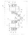
図10は、図9に示した車輪用軸受装置の具体的構造例を示す。同図の車輪用軸受装置33は第4世代型のものであり、内方部材2は、ハブ輪2Aと等速ジョイント15の外輪15aとで構成され、これらハブ輪2Aおよび等速ジョイント外輪15aに、内方部材2側の各列の軌道面が形成されている。
この車輪用軸受装置33の外方部材1に、一つのワイヤレスセンサユニット4が設置されている。ワイヤレスセンサユニット4におけるセンサ部6C〜6Eは、車輪用軸受装置33における外部から遮断された密閉空間内にあり、電力受信部8およびセンサ信号送信部9は、軸受の外部に設置されている。具体的には、ワイヤレスセンサユニット4は、回路ボックス81とセンサ設置部82とが一体化されて一体化ユニットを構成しており、回路ボックス81は外方部材1の外面に設置されている。センサ設置部82は、外方部材1に設けられた径方向の孔を通って軸受空間内に臨んでいる。回路ボックス81に上記の電力受信部8およびセンサ信号送信部9が設置され、センサ設置部82に、センサ部6C〜6Eが設けられている。センサ部6Cは回転センサを構成する磁気センサ18と、この磁気センサ18に対向する磁気エンコーダ17とでなり、そのうちの磁気センサ18がセンサ設置部82に設けられている。磁気エンコーダ17は、内方部材2の外周に設けられている。この車輪用軸受装置33は、外方部材1と内方部材2との間の軸受空間を密閉するシール83,84が両端に設けられている。センサ部6C〜6Eは、この密閉空間内に位置し、また両列の転動体3の列間に位置する。FIG. 10 shows a specific structural example of the wheel bearing device shown in FIG. The
One
このように、センサ部6C〜6Eが軸受における外部から遮断された密閉空間内にあると、外部の塵埃、異物、水等から守られるので、センサ部6C〜6Eの信頼性と耐久性が向上する。特に、車輪用軸受装置33の場合は、路面における異物や塩泥水を被り易い環境下にあるため、密閉空間内に設けられることによる信頼性,耐久性の向上効果がより効果的となる。電力受信部8およびセンサ信号送信部9は、軸受の外部にある方が、ワイヤレスによる送受の面で好ましい。
なお、図10は第4世代型の車輪用軸受装置33に適用した場合につき説明したが、第3世代型など、他の世代型の軸受装置において、上記と同様にセンサ部6C〜6Eを軸受内の外部から遮断された密閉空間に設置し、電力受信部8およびセンサ信号送信部9を軸受外部に設置しても良い。また、ワイヤレスセンサユニット4は、複数のセンサ部を有していて、一部のセンサ部が軸受外に配置されるものであっても良い。例えば、同図の車輪用軸受装置33に設置するワイヤレスセンサユニット4は、図1の参考提案例におけるいずれか一つのワイヤレスセンサユニット4A,4Bであって良い。
As described above, when the
Although FIG. 10 has been described with respect to the case where it is applied to the fourth generation type
なお、上記各実施形態では、いずれもセンサ信号受信機5を一つとしたが、センサ信号受信機5を複数設けても良い。センサ信号受信機5を複数設ける場合に、各センサ信号受信機5は、同じワイヤレスセンサユニットのセンサ信号送信部のセンサ信号を受信するものとしても良く、また異なる複数のワイヤレスセンサユニットのセンサ信号送信部のセンサ信号を受信するものとしても良い。また、センサ信号受信部と、給電電力送信部とは、必ずしも同じセンサ信号受信機5に設けられたものでなくても良く、両者を離して設置しても良い。また、センサ信号の受信をそれぞれ別個のセンサ信号受信機で行い、複数のワイヤレスセンサユニットに対して同じ給電電力送信部12でワイヤレス給電を行うようにしても良い。
また、上記実施形態は、いずれもワイヤレスの送受信を電磁波で行うようにしたが、この発明は、センサ信号および動作電力のいずれについても、ワイヤレスで送受信できれば良く、例えば、電磁結合、光、超音波等で送受信を行うものとしても良い。In each of the above embodiments, one
In the above-described embodiments, wireless transmission / reception is performed by electromagnetic waves. However, the present invention only needs to be able to wirelessly transmit / receive both sensor signals and operating power, for example, electromagnetic coupling, light, ultrasonic waves. It is good also as what transmits / receives by.
この発明は、車輪用軸受装置の他、各種産業機械、工作機械、運搬機械等において、各部の軸受や、その他の部位の検出対象のワイヤレス検出に適用することができる。 The present invention can be applied to wireless detection of bearings in various parts and detection targets of other parts in various industrial machines, machine tools, transport machines, etc. in addition to wheel bearing devices.
1…外方部材
2…内方部材
4,4A,4B…ワイヤレスセンサユニット
5,5A…センサ信号受信機
6A,6B…センサ部
8,8A,8B…電力受信部
9,9A,9B…センサ信号送信部
10A,10B…同調回路
11A,11B…検波整流回路
12…給電電力送信部
13,13A…センサ信号受信部
37A,37B…同調回路
41…切替え検波部
42…検波部
43…切替部DESCRIPTION OF
Claims (9)
Translated fromJapanese上記センサ信号受信部は、上記センサ信号送信部により送信される複数のセンサ部のセンサ信号の受信が可能なものであり、上記給電電力送信部は、上記センサ信号受信部を有するセンサ信号受信機に設けられたものであり、
上記センサ部、センサ信号送信部、および電力受信部を有するワイヤレスセンサユニットを複数設け、これら各ワイヤレスセンサユニットに、上記センサ部を複数設けると共に、各センサ部のセンサ信号が、上記センサ信号受信部で区別して受信できるようにセンサ信号を処理する信号まとめ手段を設け、上記センサ信号送信部は上記信号まとめ手段で処理されたこれら複数のセンサ部のセンサ信号を送信するものとし、
上記各ワイヤレスセンサユニットは、各ワイヤレスセンサユニットの間で互いに同じ給電用周波数の電磁波から同調回路と検波整流回路により動作電力を得る電力受信部と、検出対象の検出を行う複数のセンサ部と、各センサ部が検出した信号を上記給電用周波数とは異なる固有周波数の電磁波のセンサ信号として送信するセンサ信号送信部とを有し、上記センサ信号受信機は、上記給電用周波数の電磁波を送信する給電電力送信部と、上記各ワイヤレスセンサユニットの送信する固有周波数のセンサ信号を受信可能なセンサ信号受信部とを有するワイヤレスセンサシステム。A plurality of sensor units for detecting a detection target, a sensor signal transmission unit for wirelessly transmitting sensor signals output from these sensor units, and a power reception for wirelessly receiving operating power for driving the sensor unit and the sensor signal transmission unit A sensor signal receiving unit that receives the sensor signal transmitted by the sensor signal transmitting unit, and a power feeding power transmitting unit that wirelessly transmits operating power to the power receiving unit,
The sensor signal receiving unit is capable of receiving sensor signals from a plurality of sensor units transmitted by the sensor signal transmitting unit, and the feeding power transmitting unit is a sensor signal receiver having the sensor signal receiving unit. It is provided in
The sensor unit, the sensor signal transmitter,andRuwa ear-less sensor unit having a power receivermultiple set only, therespective word ear-less sensor units, a plurality provision of the sensor unit, the sensor signals of the sensor unit, A signal summarizing unit for processing sensor signals is provided so that the sensor signal receiving unit can receive the signals separately, and the sensor signal transmitting unit transmits the sensor signals of the plurality of sensor units processed by the signal summarizing unit.And
Each wireless sensor unit includes a power receiving unit that obtains operating power from an electromagnetic wave having the same power feeding frequency between each wireless sensor unit by a tuning circuit and a detection rectifier circuit, and a plurality of sensor units that detect a detection target, A sensor signal transmission unit that transmits a signal detected by each sensor unit as a sensor signal of an electromagnetic wave having a natural frequency different from the power supply frequency, and the sensor signal receiver transmits the electromagnetic wave of the power supply frequency. Wa ear-less sensorsystem comprising a feeding power transmitting unit, and a possible sensor signal receiving unit receiving the sensor signal of the natural frequency of transmission of the respective wireless sensor units.
複列の軌道面を有する外方部材と、上記軌道面に対向する軌道面を有する内方部材と、対向する両列の軌道面間に介在した複数の転動体とを備え、車体に対して車輪を回転自在に支持する車輪用軸受装置に設けたことを特徴とするワイヤレスセンサ付車輪用軸受装置。The wireless sensor system according to any one of claims 1 to7 ,
An outer member having a double-row raceway surface, an inner member having a raceway surface facing the raceway surface, and a plurality of rolling elements interposed between the opposing raceway surfaces, A wheel bearing device with a wireless sensor provided in a wheel bearing device for rotatably supporting a wheel.
Priority Applications (6)
| Application Number | Priority Date | Filing Date | Title |
|---|---|---|---|
| JP2003306181AJP4963006B2 (en) | 2002-09-09 | 2003-08-29 | Wireless sensor system and wheel bearing device with wireless sensor |
| CNB038212897ACN100416617C (en) | 2002-09-09 | 2003-09-08 | Wireless sensing system and bearing assembly with wireless sensor |
| PCT/JP2003/011459WO2004023422A1 (en) | 2002-09-09 | 2003-09-08 | Wireless sensor system and bearing device having wireless sensor |
| AU2003262003AAU2003262003A1 (en) | 2002-09-09 | 2003-09-08 | Wireless sensor system and bearing device having wireless sensor |
| US10/526,903US7561035B2 (en) | 2002-09-09 | 2003-09-08 | Wireless sensor system and bearing assembly equipped with the same |
| EP03794288AEP1542190B1 (en) | 2002-09-09 | 2003-09-08 | Wireless sensor system and bearing device having wireless sensor |
Applications Claiming Priority (3)
| Application Number | Priority Date | Filing Date | Title |
|---|---|---|---|
| JP2002262262 | 2002-09-09 | ||
| JP2002262262 | 2002-09-09 | ||
| JP2003306181AJP4963006B2 (en) | 2002-09-09 | 2003-08-29 | Wireless sensor system and wheel bearing device with wireless sensor |
Publications (2)
| Publication Number | Publication Date |
|---|---|
| JP2004133911A JP2004133911A (en) | 2004-04-30 |
| JP4963006B2true JP4963006B2 (en) | 2012-06-27 |
Family
ID=31980597
Family Applications (1)
| Application Number | Title | Priority Date | Filing Date |
|---|---|---|---|
| JP2003306181AExpired - LifetimeJP4963006B2 (en) | 2002-09-09 | 2003-08-29 | Wireless sensor system and wheel bearing device with wireless sensor |
Country Status (6)
| Country | Link |
|---|---|
| US (1) | US7561035B2 (en) |
| EP (1) | EP1542190B1 (en) |
| JP (1) | JP4963006B2 (en) |
| CN (1) | CN100416617C (en) |
| AU (1) | AU2003262003A1 (en) |
| WO (1) | WO2004023422A1 (en) |
Families Citing this family (57)
| Publication number | Priority date | Publication date | Assignee | Title |
|---|---|---|---|---|
| US7603894B2 (en)* | 2000-09-08 | 2009-10-20 | Automotive Technologies International, Inc. | Self-powered tire monitoring system |
| US20060153482A1 (en)* | 2003-04-07 | 2006-07-13 | Ntn Corporation | Wheel support bearing assembly with built-in load sensor |
| US20070065060A1 (en)* | 2003-07-04 | 2007-03-22 | Ntn Corporation | Wheel support bearing assembly with built-in load sensor |
| DE10344575A1 (en)* | 2003-09-25 | 2005-04-28 | Siemens Ag | Device for transmitting data and portable electronic device and field device for such a device |
| JP2005098941A (en)* | 2003-09-26 | 2005-04-14 | Ntn Corp | Bearing unit with wireless sensor |
| DE102004004292A1 (en)* | 2004-01-28 | 2005-09-08 | Siemens Ag | Arrangement and method for bidirectionally transmitting signals in a motor vehicle |
| FR2872116B1 (en)* | 2004-06-29 | 2006-10-20 | Michelin Soc Tech | AUTOMOTIVE VEHICLE WHEEL PASSAGE COMPRISING AN ELECTRIC CIRCUIT AND ASSEMBLY OF A WHEEL PASSAGE AND FEED MEANS |
| WO2006038557A1 (en) | 2004-10-01 | 2006-04-13 | Murata Manufacturing Co., Ltd. | Tire pressure monitoring device |
| WO2006051590A1 (en)* | 2004-11-11 | 2006-05-18 | Hitachi, Ltd. | Rotation detection device |
| JP4498104B2 (en)* | 2004-11-16 | 2010-07-07 | キヤノン株式会社 | Monitoring device, control method thereof, and program |
| US7466240B2 (en)* | 2005-01-25 | 2008-12-16 | The Retents Of The University Of California | Wireless sensing node powered by energy conversion from sensed system |
| JP2006242707A (en)* | 2005-03-02 | 2006-09-14 | Denso Corp | Tire air pressure detection device |
| DE102005032145A1 (en)* | 2005-07-07 | 2007-01-11 | Zf Friedrichshafen Ag | Joint for a motor vehicle |
| JP2007145262A (en)* | 2005-11-30 | 2007-06-14 | Pacific Ind Co Ltd | Tire condition monitoring system |
| FR2896726B1 (en)* | 2006-01-31 | 2010-06-04 | Michelin Soc Tech | PNEUMATIC, WHEEL OR PNEUMATIC ASSEMBLY AND WHEEL EQUIPPED WITH A DEVICE FOR COUNTING THE NUMBER OF ROTATIONS. |
| US8652040B2 (en) | 2006-12-19 | 2014-02-18 | Valencell, Inc. | Telemetric apparatus for health and environmental monitoring |
| JP4591503B2 (en)* | 2007-12-26 | 2010-12-01 | 日産自動車株式会社 | Air pressure monitoring device |
| US7938074B2 (en)* | 2009-01-22 | 2011-05-10 | Deere & Company | Pressure sensing system for a planter |
| CN102460188B (en) | 2009-04-16 | 2015-09-16 | 全景电力有限公司 | Device and method for power consumption measurement at circuit breaker point |
| US9134348B2 (en) | 2009-04-16 | 2015-09-15 | Panoramic Power Ltd. | Distributed electricity metering system |
| US9678114B2 (en) | 2009-04-16 | 2017-06-13 | Panoramic Power Ltd. | Apparatus and methods thereof for error correction in split core current transformers |
| JP5424731B2 (en)* | 2009-06-15 | 2014-02-26 | Ntn株式会社 | Tire pressure monitoring system |
| US20110029156A1 (en)* | 2009-07-31 | 2011-02-03 | Gm Global Technology Operations, Inc. | Wireless sensor system for a motor vehicle |
| KR101059657B1 (en)* | 2009-10-07 | 2011-08-25 | 삼성전기주식회사 | Wireless power transceiver and method |
| US8560151B2 (en)* | 2010-05-11 | 2013-10-15 | Cartasite, Inc. | Dynamic monitoring of mobile railway car undercarriage |
| CN102338642A (en)* | 2010-07-27 | 2012-02-01 | 昆达电脑科技(昆山)有限公司 | Wireless vehicle speed sensing device and method |
| CN102053016B (en)* | 2010-11-08 | 2013-07-17 | 江苏大学 | System for monitoring vibration of rotating machinery rolling bearing in wireless mode |
| CN102407742B (en)* | 2011-09-29 | 2014-01-15 | 华南理工大学 | Vehicle networking wheel-mounted sensor system and method based on RFID self-supply |
| CN102680123A (en)* | 2012-05-30 | 2012-09-19 | 西安交通大学 | System and method for on-line monitoring temperature and stress of retainer |
| DE112013006872T5 (en)* | 2013-03-27 | 2015-12-24 | Aktiebolaget Skf | hub unit |
| WO2015035568A1 (en) | 2013-09-11 | 2015-03-19 | 3M Innovative Properties Company | Systems and methods for monitoring temperature of electrical conductor |
| CN104236727A (en)* | 2013-12-02 | 2014-12-24 | 鸿富锦精密工业(武汉)有限公司 | Containing box control system and method |
| US10243724B2 (en)* | 2014-02-12 | 2019-03-26 | Infineon Technologies Ag | Sensor subassembly and method for sending a data signal |
| JP2016022889A (en)* | 2014-07-23 | 2016-02-08 | 太平洋工業株式会社 | Tire condition monitoring device |
| EP3192715B1 (en)* | 2014-09-12 | 2021-03-17 | NTN Corporation | Bearing abnormality sensing system for railway vehicle |
| CN105490393A (en)* | 2014-09-19 | 2016-04-13 | 上海海拉电子有限公司 | Automobile wireless transmission system and transmission method |
| US9683895B2 (en)* | 2014-12-29 | 2017-06-20 | Bosch Automotive Service Solutions Inc. | Non-contact infrared temperature sensor with wireless functionality |
| US9891252B2 (en) | 2015-07-28 | 2018-02-13 | Panoramic Power Ltd. | Thermal management of self-powered power sensors |
| US10024885B2 (en) | 2015-07-28 | 2018-07-17 | Panoramic Power Ltd. | Thermal management of self-powered power sensors |
| JP6484156B2 (en)* | 2015-10-08 | 2019-03-13 | 川崎重工業株式会社 | Temperature sensor unit with radio communication function for railcar bogie |
| US9815342B2 (en) | 2015-11-20 | 2017-11-14 | Ford Global Technologies, Llc | Vehicle positioning to charge TPMS batteries |
| JP6707866B2 (en) | 2015-12-04 | 2020-06-10 | 日本精工株式会社 | Rolling bearing unit for wheel support |
| US10275477B2 (en)* | 2016-01-25 | 2019-04-30 | International Business Machines Corporation | Processing path determination |
| US10093349B2 (en)* | 2016-03-02 | 2018-10-09 | Trw Automotive U.S. Llc | Monitoring of an electric motor in an electric power steering assembly |
| CN105763158B (en)* | 2016-04-26 | 2017-08-25 | 广东大粤新能源科技股份有限公司 | Method for monitoring photovoltaic power station through mobile phone |
| EP3396325A1 (en)* | 2017-04-25 | 2018-10-31 | Siemens Aktiengesellschaft | Device for monitoring a machine or unit |
| WO2019022794A1 (en) | 2017-07-26 | 2019-01-31 | Panoramic Power Ltd. | Timing synchronization of self-powered power sensors and a central controller collecting samples therefrom |
| EP3659236B1 (en) | 2017-07-26 | 2023-09-13 | Panoramic Power Ltd. | Transmission of time stamps of samples of self-powered power sensor |
| EP3658923A4 (en) | 2017-07-26 | 2021-04-21 | Panoramic Power Ltd. | SYSTEM AND METHOD FOR CLOCK SYNCHRONIZATION OF A SELF-PROPELLED POWER SENSOR |
| CN108513276B (en)* | 2018-04-09 | 2020-07-17 | 珠海爱必途科技有限公司 | Closed space communication method |
| US11479065B2 (en)* | 2019-09-16 | 2022-10-25 | Sensata Technolgies, Inc. | Position sensing system and method for locating tire pressure monitoring sensors using correlation to wheel end sensors |
| US11231069B2 (en)* | 2019-10-17 | 2022-01-25 | Aktiebolaget Skf | Wheel hub bearing provided with a wireless power transfer device |
| CN111121988B (en)* | 2019-12-30 | 2021-05-25 | 中国船舶重工集团公司第七一一研究所 | Temperature measuring device and temperature measuring method suitable for V-shaped engine connecting rod bearing bush |
| CN114379604A (en)* | 2020-10-16 | 2022-04-22 | 舍弗勒技术股份两合公司 | Wireless sensor wheel set bearing device for railway vehicle |
| DE102022110161A1 (en) | 2021-04-28 | 2022-11-03 | Dana Automotive Systems Group, Llc | SYSTEMS AND METHODS FOR PREDICTING COMPONENT DEGRADATION |
| US20230172094A1 (en)* | 2021-12-02 | 2023-06-08 | Cnh Industrial America Llc | Wheel assembly with integrated sensor for an agriculutral implement |
| CN114509265A (en)* | 2022-04-20 | 2022-05-17 | 浙江五洲新春集团股份有限公司 | Wireless power supply's intelligent bearing on-line monitoring device |
Family Cites Families (46)
| Publication number | Priority date | Publication date | Assignee | Title |
|---|---|---|---|---|
| US3723966A (en)* | 1970-09-14 | 1973-03-27 | Bendix Corp | Interrogating tire pressure indicator |
| JPS5639601A (en)* | 1979-09-06 | 1981-04-15 | Mitsubishi Electric Corp | Antenna for solar generation of electricity |
| US4263579A (en)* | 1979-11-15 | 1981-04-21 | Cgs Research And Development, Inc. | Tire pressure alarm |
| US4609905A (en)* | 1984-05-11 | 1986-09-02 | Eaton Corporation | Tire condition monitoring system |
| DE3503347A1 (en)* | 1985-02-01 | 1986-08-14 | Dr.Ing.H.C. F. Porsche Ag, 7000 Stuttgart | DEVICE FOR WIRELESS MEASURING SIGNAL TRANSMISSION |
| JPS6460118A (en)* | 1987-08-31 | 1989-03-07 | Hochiki Co | Radio transmission equipment |
| US4966034A (en)* | 1988-04-28 | 1990-10-30 | Schrader Automotive, Inc. | On-board tire pressure indicating system performing temperature-compensated pressure measurement, and pressure measurement circuitry thereof |
| JP2757267B2 (en) | 1990-07-06 | 1998-05-25 | 山武ハネウエル株式会社 | Current meter |
| JP3024784B2 (en)* | 1990-09-26 | 2000-03-21 | 株式会社ブリヂストン | Tire internal monitoring device |
| DE4033053C1 (en)* | 1990-10-18 | 1992-03-05 | Hottinger Baldwin Messtechnik Gmbh, 6100 Darmstadt, De | |
| FR2670889B1 (en)* | 1990-11-30 | 1995-05-24 | Skf France | ENGLISH RACKED WOODEN STAIRCASES, POSTS, RAILS, SIMPLIFIED MANUFACTURING AND LAYING GUARDS. |
| JPH0542868A (en)* | 1991-08-13 | 1993-02-23 | Zexel Corp | Fade detecting device of brake |
| JPH0676193A (en)* | 1992-06-10 | 1994-03-18 | Seiko Epson Corp | Method and apparatus for measuring information in vacuum chamber |
| JPH0810232A (en) | 1994-06-29 | 1996-01-16 | Casio Comput Co Ltd | Bio-information processing system |
| US5661651A (en) | 1995-03-31 | 1997-08-26 | Prince Corporation | Wireless vehicle parameter monitoring system |
| JPH095178A (en)* | 1995-06-22 | 1997-01-10 | Hitachi Ltd | Torque detection system |
| JPH1010141A (en) | 1996-04-26 | 1998-01-16 | Toyota Motor Corp | Magnetic rotation detector |
| DE59706501D1 (en)* | 1996-05-29 | 2002-04-04 | Iq Mobil Electronics Gmbh | DEVICE FOR WIRELESS TRANSMISSION FROM MOVING PARTS |
| JP3604509B2 (en)* | 1996-07-02 | 2004-12-22 | 横浜ゴム株式会社 | Vehicle tire pressure monitoring system |
| JPH11238193A (en)* | 1998-02-19 | 1999-08-31 | Matsue Anzen Shokai:Kk | Data communication method and device therefor |
| DE60002557T2 (en)* | 1999-02-11 | 2003-12-11 | Emtop Ltd., London | SIGNAL TRANSMISSION DEVICE AND METHOD, SENSOR DEVICE AND TIRE PRESSURE MEASURING DEVICE WITH SUCH A SIGNAL TRANSMISSION DEVICE |
| AU2053700A (en) | 1999-05-17 | 2000-12-05 | Goodyear Tire And Rubber Company, The | Power-on reset for transponder |
| US6980084B1 (en) | 1999-05-17 | 2005-12-27 | The Goodyear Tire & Rubber Company | Power-on reset for transponder |
| JP2001151090A (en)* | 1999-11-30 | 2001-06-05 | Ntn Corp | Antilock braking system |
| JP2001349794A (en)* | 2000-06-12 | 2001-12-21 | Dainippon Printing Co Ltd | Pressure detection system using signal transmission device and pressure detection roll |
| JP2002055113A (en)* | 2000-08-09 | 2002-02-20 | Ntn Corp | Bearing device for wheel |
| US6535116B1 (en)* | 2000-08-17 | 2003-03-18 | Joe Huayue Zhou | Wireless vehicle monitoring system |
| FR2817509B1 (en)* | 2000-12-05 | 2003-08-29 | Trw France | WHEEL PARAMETER MEASUREMENT SYSTEM AND MEASUREMENT DETECTOR FOR SUCH A SYSTEM |
| JP2003058976A (en) | 2001-06-04 | 2003-02-28 | Nsk Ltd | Wireless sensor, rolling bearing device, management device, and monitoring device |
| JP2002364661A (en) | 2001-06-11 | 2002-12-18 | Nsk Ltd | Bearing preload measuring method and spindle unit |
| US7034711B2 (en) | 2001-08-07 | 2006-04-25 | Nsk Ltd. | Wireless sensor, rolling bearing with sensor, management apparatus and monitoring system |
| US6696935B2 (en) | 2001-09-10 | 2004-02-24 | Gentex Corporation | Tire monitoring system |
| JP2003146196A (en) | 2001-11-12 | 2003-05-21 | Nsk Ltd | Rotational speed detector for wheels |
| EP1329727A1 (en) | 2001-10-18 | 2003-07-23 | Nsk Ltd | Rotation-speed sensor device |
| FR2832272B1 (en)* | 2001-11-09 | 2004-09-24 | Commissariat Energie Atomique | PASSIVE DEVICE FOR INCREASING TRANSMISSION EFFICIENCY OF RADIO FREQUENCY SYSTEMS |
| JP2003151064A (en) | 2001-11-16 | 2003-05-23 | Honda Motor Co Ltd | Tire sensor unit |
| JP2003151063A (en) | 2001-11-16 | 2003-05-23 | Honda Motor Co Ltd | Tire monitoring system |
| US7018106B2 (en) | 2001-12-14 | 2006-03-28 | Ntn Corporation | Vehicle mounted bearing assembly |
| JP2003187368A (en) | 2001-12-14 | 2003-07-04 | Ntn Corp | Bearing device for vehicle |
| US6838985B2 (en)* | 2002-03-25 | 2005-01-04 | Lear Corporation | System and method for remote tire pressure monitoring with low frequency initiation |
| US20040150516A1 (en)* | 2003-02-05 | 2004-08-05 | Delphi Technologies, Inc. | Wireless wheel speed sensor system |
| US6958685B2 (en) | 2003-08-01 | 2005-10-25 | Siemens Vdo Automotive Corporation | Asynchronous localization signals for tire pressure monitoring system |
| US7205885B2 (en)* | 2003-08-25 | 2007-04-17 | Siemens Vdo Automotive Corporation | Tire sensor communication system |
| US7104438B2 (en) | 2003-10-22 | 2006-09-12 | The Goodyear Tire & Rubber Company | Method of integrating tire identification into a vehicle information system |
| US7148793B2 (en) | 2004-01-30 | 2006-12-12 | Trw Automotive Us Llc | Tire parameter sensing system having auto-location feature and associated method |
| US7580696B2 (en)* | 2004-12-14 | 2009-08-25 | Lear Corporation | Self-aligning vehicular transmitter system |
- 2003
- 2003-08-29JPJP2003306181Apatent/JP4963006B2/ennot_activeExpired - Lifetime
- 2003-09-08EPEP03794288Apatent/EP1542190B1/ennot_activeExpired - Lifetime
- 2003-09-08CNCNB038212897Apatent/CN100416617C/ennot_activeExpired - Fee Related
- 2003-09-08USUS10/526,903patent/US7561035B2/ennot_activeExpired - Fee Related
- 2003-09-08AUAU2003262003Apatent/AU2003262003A1/ennot_activeAbandoned
- 2003-09-08WOPCT/JP2003/011459patent/WO2004023422A1/enactiveApplication Filing
Also Published As
| Publication number | Publication date |
|---|---|
| US7561035B2 (en) | 2009-07-14 |
| CN1682257A (en) | 2005-10-12 |
| WO2004023422A1 (en) | 2004-03-18 |
| AU2003262003A1 (en) | 2004-03-29 |
| EP1542190A1 (en) | 2005-06-15 |
| US20050258950A1 (en) | 2005-11-24 |
| EP1542190B1 (en) | 2011-06-08 |
| CN100416617C (en) | 2008-09-03 |
| EP1542190A4 (en) | 2010-03-17 |
| JP2004133911A (en) | 2004-04-30 |
Similar Documents
| Publication | Publication Date | Title |
|---|---|---|
| JP4963006B2 (en) | Wireless sensor system and wheel bearing device with wireless sensor | |
| CN100428285C (en) | Wireless sensor system and bearing unit with wireless sensors | |
| EP1342633B1 (en) | Rotation detecting device and anti-skid braking system using the same | |
| US7688216B2 (en) | Wireless sensor system and wheel support bearing assembly utilizing the same | |
| US6879149B2 (en) | Wheel support bearing assembly | |
| US20070159352A1 (en) | Bearing assembly having built-in wireless sensor | |
| JP2004127276A (en) | Wireless sensor system and bearing device with wireless sensor | |
| JP2006138873A (en) | Rolling bearing unit with rotating speed detector | |
| US7164265B2 (en) | Bearing assembly with rotation sensing device | |
| JP2006005978A (en) | Wireless sensor system and bearing device with wireless sensor | |
| JP2005078341A (en) | Wireless sensor system and bearing device with wireless sensor | |
| JP2020049982A (en) | Hub bearing device with signal transmission function | |
| US7336067B2 (en) | Sensor assembly, sealing device, and roller bearing apparatus for vehicles having integrated connector and ring | |
| JP2005092555A (en) | Wireless sensor system and bearing device with wireless sensor | |
| JP2003121454A (en) | Rolling bearing unit with rotation speed detector | |
| JP2003157485A (en) | Signal transmission device indicating the state of the wheel support | |
| WO2005029436A1 (en) | Wireless sensor system and wireless sensor-equipped bearing device | |
| JP2003278779A (en) | Power generator-equipped wheel bearing device | |
| JP2005092705A (en) | Wireless sensor system and bearing device with wireless sensor | |
| WO2005028218A1 (en) | Wheel bearing apparatus having wireless sensor | |
| JP2005084998A (en) | Bearing device with wireless sensor | |
| JP2003287046A (en) | Bearing device for wheel with generator | |
| JP2006170625A (en) | Bearing with rotation sensor | |
| JP2005258529A (en) | Wireless sensor-equipped bearing device for wheel | |
| JP2006170626A (en) | Bearing with rotation sensor |
Legal Events
| Date | Code | Title | Description |
|---|---|---|---|
| A621 | Written request for application examination | Free format text:JAPANESE INTERMEDIATE CODE: A621 Effective date:20060403 | |
| A131 | Notification of reasons for refusal | Free format text:JAPANESE INTERMEDIATE CODE: A131 Effective date:20091222 | |
| A521 | Written amendment | Free format text:JAPANESE INTERMEDIATE CODE: A523 Effective date:20100218 | |
| A131 | Notification of reasons for refusal | Free format text:JAPANESE INTERMEDIATE CODE: A131 Effective date:20110118 | |
| TRDD | Decision of grant or rejection written | ||
| A01 | Written decision to grant a patent or to grant a registration (utility model) | Free format text:JAPANESE INTERMEDIATE CODE: A01 Effective date:20120321 | |
| A01 | Written decision to grant a patent or to grant a registration (utility model) | Free format text:JAPANESE INTERMEDIATE CODE: A01 | |
| A61 | First payment of annual fees (during grant procedure) | Free format text:JAPANESE INTERMEDIATE CODE: A61 Effective date:20120321 | |
| R150 | Certificate of patent or registration of utility model | Free format text:JAPANESE INTERMEDIATE CODE: R150 | |
| FPAY | Renewal fee payment (event date is renewal date of database) | Free format text:PAYMENT UNTIL: 20150406 Year of fee payment:3 | |
| R250 | Receipt of annual fees | Free format text:JAPANESE INTERMEDIATE CODE: R250 | |
| R250 | Receipt of annual fees | Free format text:JAPANESE INTERMEDIATE CODE: R250 | |
| R250 | Receipt of annual fees | Free format text:JAPANESE INTERMEDIATE CODE: R250 | |
| R250 | Receipt of annual fees | Free format text:JAPANESE INTERMEDIATE CODE: R250 | |
| R250 | Receipt of annual fees | Free format text:JAPANESE INTERMEDIATE CODE: R250 |