JP4962205B2 - Method and apparatus for producing silicon carbide single crystal - Google Patents
Method and apparatus for producing silicon carbide single crystalDownload PDFInfo
- Publication number
- JP4962205B2 JP4962205B2JP2007207643AJP2007207643AJP4962205B2JP 4962205 B2JP4962205 B2JP 4962205B2JP 2007207643 AJP2007207643 AJP 2007207643AJP 2007207643 AJP2007207643 AJP 2007207643AJP 4962205 B2JP4962205 B2JP 4962205B2
- Authority
- JP
- Japan
- Prior art keywords
- silicon carbide
- raw material
- sublimation gas
- gas supply
- supply member
- Prior art date
- Legal status (The legal status is an assumption and is not a legal conclusion. Google has not performed a legal analysis and makes no representation as to the accuracy of the status listed.)
- Active
Links
- 229910010271silicon carbideInorganic materials0.000titleclaimsdescription210
- HBMJWWWQQXIZIP-UHFFFAOYSA-Nsilicon carbideChemical compound[Si+]#[C-]HBMJWWWQQXIZIP-UHFFFAOYSA-N0.000titleclaimsdescription209
- 239000013078crystalSubstances0.000titleclaimsdescription150
- 238000000034methodMethods0.000titledescription4
- 239000002994raw materialSubstances0.000claimsdescription232
- 238000000859sublimationMethods0.000claimsdescription224
- 230000008022sublimationEffects0.000claimsdescription224
- 238000004519manufacturing processMethods0.000claimsdescription53
- 230000000149penetrating effectEffects0.000claimsdescription16
- 238000010438heat treatmentMethods0.000claimsdescription12
- XUIMIQQOPSSXEZ-UHFFFAOYSA-NSiliconChemical compound[Si]XUIMIQQOPSSXEZ-UHFFFAOYSA-N0.000claimsdescription11
- 239000000463materialSubstances0.000claimsdescription11
- 229910052710siliconInorganic materials0.000claimsdescription11
- 239000010703siliconSubstances0.000claimsdescription11
- 239000000758substrateSubstances0.000claims12
- 238000003763carbonizationMethods0.000claims6
- 239000007789gasSubstances0.000description152
- 239000000843powderSubstances0.000description107
- 238000010586diagramMethods0.000description18
- OKTJSMMVPCPJKN-UHFFFAOYSA-NCarbonChemical compound[C]OKTJSMMVPCPJKN-UHFFFAOYSA-N0.000description10
- 229910052799carbonInorganic materials0.000description8
- 239000002245particleSubstances0.000description6
- 230000007423decreaseEffects0.000description4
- 230000007547defectEffects0.000description4
- 239000003575carbonaceous materialSubstances0.000description3
- IJGRMHOSHXDMSA-UHFFFAOYSA-NAtomic nitrogenChemical compoundN#NIJGRMHOSHXDMSA-UHFFFAOYSA-N0.000description2
- 230000002349favourable effectEffects0.000description2
- 229910002804graphiteInorganic materials0.000description2
- 239000010439graphiteSubstances0.000description2
- NJPPVKZQTLUDBO-UHFFFAOYSA-NnovaluronChemical compoundC1=C(Cl)C(OC(F)(F)C(OC(F)(F)F)F)=CC=C1NC(=O)NC(=O)C1=C(F)C=CC=C1FNJPPVKZQTLUDBO-UHFFFAOYSA-N0.000description2
- 229910052715tantalumInorganic materials0.000description2
- GUVRBAGPIYLISA-UHFFFAOYSA-Ntantalum atomChemical compound[Ta]GUVRBAGPIYLISA-UHFFFAOYSA-N0.000description2
- 230000004323axial lengthEffects0.000description1
- 238000007796conventional methodMethods0.000description1
- 239000002019doping agentSubstances0.000description1
- 239000001257hydrogenSubstances0.000description1
- 229910052739hydrogenInorganic materials0.000description1
- 125000004435hydrogen atomChemical class[H]*0.000description1
- 239000011261inert gasSubstances0.000description1
- 239000011810insulating materialSubstances0.000description1
- 238000005304joiningMethods0.000description1
- 238000002844meltingMethods0.000description1
- 230000008018meltingEffects0.000description1
- 229910052757nitrogenInorganic materials0.000description1
- 239000011148porous materialSubstances0.000description1
- 238000002360preparation methodMethods0.000description1
- 239000003870refractory metalSubstances0.000description1
- WFKWXMTUELFFGS-UHFFFAOYSA-NtungstenChemical compound[W]WFKWXMTUELFFGS-UHFFFAOYSA-N0.000description1
- 229910052721tungstenInorganic materials0.000description1
- 239000010937tungstenSubstances0.000description1
Images


Landscapes
- Crystals, And After-Treatments Of Crystals (AREA)
Description
Translated fromJapanese本発明は、パワーMOSFET等の素材に利用することができる炭化珪素(以下、SiCという)単結晶の製造方法および装置に関するものである。 The present invention relates to a method and an apparatus for producing silicon carbide (hereinafter referred to as SiC) single crystal that can be used as a material for a power MOSFET or the like.
従来より、SiC単結晶を成長させる方法が提案されている(例えば、特許文献1参照)。具体的に、特許文献1では、黒鉛製の坩堝内に種結晶を接合すると共に、坩堝底部に配したSiC粉末原料を例えば2300℃に加熱することで、SiC粉末原料を昇華させ、その昇華させたガスを原料温度よりも低い温度に設定された種結晶上に結晶化させる手法が提案されている。
しかしながら、上記従来の技術では、坩堝底部に配されたSiC粉末原料を加熱して昇華させていくと、SiC粉末原料の上層部から主としてシリコンが昇華していくため、SiC粉末原料のうち上層部のシリコンが枯渇して、当該上層部が固まった枯渇層となってしまう。これにより、成長時間と共にSiC単結晶の成長速度が低下してしまう。また、枯渇層によって昇華ガスの供給量が減少し、長時間成長ができなくなってしまう。 However, in the above conventional technique, when the SiC powder raw material arranged at the bottom of the crucible is heated and sublimated, silicon is mainly sublimated from the upper layer portion of the SiC powder raw material. The silicon is depleted and the upper layer becomes a depleted layer. As a result, the growth rate of the SiC single crystal decreases with the growth time. In addition, the supply amount of sublimation gas decreases due to the depleted layer, and growth cannot be performed for a long time.
また、SiC粉末原料の上層部に形成される枯渇層がSiC粉末原料の上層部に蓋をする役割をし、未だ昇華していない下層部のSiC粉末原料が残留して無駄になってしまう。さらに、シリコンが抜けた枯渇層からカーボン粒子が飛散してSiC単結晶に取り込まれ、SiC単結晶に結晶欠陥が発生してしまうという問題がある。 Moreover, the depletion layer formed in the upper layer part of the SiC powder raw material serves to cover the upper layer part of the SiC powder raw material, and the SiC powder raw material in the lower layer part not yet sublimated remains and is wasted. Furthermore, there is a problem that carbon particles are scattered from the depleted layer from which silicon has been removed and taken into the SiC single crystal, causing crystal defects in the SiC single crystal.
本発明は、上記点に鑑み、SiC単結晶の成長速度の低下を抑制することを第1の目的とし、SiC単結晶を長時間成長させることを第2の目的とし、未昇華状態のSiC粉末原料の残留を低減することを第3の目的とし、カーボン粒子によるSiC単結晶の結晶欠陥を防止することを第4の目的とする。 In view of the above points, the present invention has a first object to suppress a decrease in the growth rate of a SiC single crystal, and a second object to grow a SiC single crystal for a long time. A third object is to reduce the residual material, and a fourth object is to prevent crystal defects in the SiC single crystal due to the carbon particles.
上記目的を達成するため、本発明の第1の特徴では、中空筒状であって、筒の外壁面から内壁面に貫通する複数の小孔(10a)を備え、筒の一端が炭化珪素原料(4)に埋め込まれ、筒の他端が炭化珪素原料(4)から突出するように容器本体(1a)内に配置される昇華ガス供給部材(10)を有することを特徴とする。 In order to achieve the above object, according to a first feature of the present invention, a hollow cylinder has a plurality of small holes (10a) penetrating from an outer wall surface to an inner wall surface, and one end of the cylinder is a silicon carbide raw material. (4) It has a sublimation gas supply member (10) which is embedded in the container body (1a) so that the other end of the cylinder protrudes from the silicon carbide raw material (4).
これによると、炭化珪素原料(4)の下層部で生じる昇華ガスを小孔(10a)から昇華ガス供給部材(10)内に流入させることができる。したがって、炭化珪素原料(4)の上層部に枯渇層(4a)が形成されて昇華ガスが炭化珪素原料(4)の表面から成長空間領域(5)に供給されなくなっても、昇華ガス供給部材(10)を経由して炭化珪素原料(4)の下層部で生じる昇華ガスを成長空間領域(5)に供給し続けることができる。これにより、炭化珪素単結晶(20)の成長速度が低下してしまうことを防止することができる。 According to this, the sublimation gas generated in the lower layer portion of the silicon carbide raw material (4) can be caused to flow into the sublimation gas supply member (10) from the small hole (10a). Therefore, even if the depletion layer (4a) is formed in the upper layer portion of the silicon carbide raw material (4) and the sublimation gas is not supplied from the surface of the silicon carbide raw material (4) to the growth space region (5), the sublimation gas supply member The sublimation gas generated in the lower layer portion of the silicon carbide raw material (4) can be continuously supplied to the growth space region (5) via (10). Thereby, it can prevent that the growth rate of a silicon carbide single crystal (20) falls.
また、炭化珪素原料(4)の下層部で生じる昇華ガスを成長空間領域(5)に供給し続けることができるため、炭化珪素単結晶(20)を成長させる時間を長くすることができる。さらに、炭化珪素原料(4)の下層部で生じる昇華ガスを成長空間領域(5)に導くことができるため、炭化珪素原料(4)の下層部が未昇華状態で残留して無駄にならないようにすることができる。 Moreover, since the sublimation gas generated in the lower layer portion of the silicon carbide raw material (4) can be continuously supplied to the growth space region (5), the time for growing the silicon carbide single crystal (20) can be extended. Furthermore, since the sublimation gas generated in the lower layer portion of the silicon carbide raw material (4) can be guided to the growth space region (5), the lower layer portion of the silicon carbide raw material (4) remains in an unsublimated state and is not wasted. Can be.
また、昇華ガス供給部材(10)を容器本体(1a)内に複数配置することができ、容器本体(1a)の底面から昇華ガス供給部材(10)の他端までの高さを異なるようにすることができる。 Further, a plurality of sublimation gas supply members (10) can be arranged in the container main body (1a) so that the height from the bottom surface of the container main body (1a) to the other end of the sublimation gas supply member (10) is different. can do.
これによると、昇華ガス供給部材(10)から成長空間領域(5)に供給される昇華ガスの供給位置を調整することができ、成長空間領域(5)に昇華ガスの流れを作ることができる。 According to this, the supply position of the sublimation gas supplied from the sublimation gas supply member (10) to the growth space region (5) can be adjusted, and a flow of sublimation gas can be created in the growth space region (5). .
また、複数の昇華ガス供給部材(10)の各他端のうち、いずれかを折り曲げることができる。これにより、結晶成長に良好な昇華ガスの流れを作ることができる。 Further, any one of the other ends of the plurality of sublimation gas supply members (10) can be bent. Thereby, the flow of sublimation gas favorable for crystal growth can be made.
本発明の第2の特徴では、昇華ガス供給部材(10)として、炭化珪素原料(4)に埋め込まれる部分が立体格子状をなしていることが特徴となっている。In the second feature of the present invention, the sublimation gas supply member (10)is characterized in that the portion embedded in the silicon carbide raw material (4) has a three-dimensional lattice shape.
これによると、昇華ガス供給部材(10)と炭化珪素原料(4)との接触面積を増加させることができ、成長空間領域(5)への昇華ガスの供給効率を向上させることができる。 According to this, the contact area between the sublimation gas supply member (10) and the silicon carbide raw material (4) can be increased, and the supply efficiency of the sublimation gas to the growth space region (5) can be improved.
また、本発明の第3の特徴では、円形および板状であって、容器本体(1a)の内径と同じ径であり、板の一面側に昇華ガス供給部材(10)の一端が位置し、板の他面側に昇華ガス供給部材(10)の他端が位置するように板に昇華ガス供給部材(10)が差し込まれると共に、炭化珪素原料(4)の表面に接触するように配置される原料蓋(40)を備えることが特徴となっている。Further,in the third feature of the present invention, it is circular and plate-shaped, has the same diameter as the inner diameter of the container body (1a), and one end of the sublimation gas supply member (10) is located on one side of the plate, The sublimation gas supply member (10) is inserted into the plate so that the other end of the sublimation gas supply member (10) is located on the other surface side of the plate, and is disposed so as to contact the surface of the silicon carbide raw material (4). It ischaracterized by comprising a raw material lid (40).
これによると、炭化珪素原料(4)内で生じた昇華ガスを昇華ガス供給部材(10)のみから成長空間領域(5)に供給することができる。すなわち、原料蓋(40)から突出する昇華ガス供給部材(10)の位置や高さ等を調整することによって、成長空間領域(5)に良好な昇華ガスの流れを作ることができる。 According to this, the sublimation gas generated in the silicon carbide raw material (4) can be supplied to the growth space region (5) only from the sublimation gas supply member (10). That is, by adjusting the position and height of the sublimation gas supply member (10) protruding from the raw material lid (40), a good flow of sublimation gas can be created in the growth space region (5).
また、原料蓋(40)で炭化珪素原料(4)を覆うことができるため、シリコンが抜けた枯渇層(4a)からカーボン粒子が飛散することを防止することができる。したがって、カーボン粒子による炭化珪素単結晶(20)の結晶欠陥を抑制することができる。 Moreover, since the silicon carbide raw material (4) can be covered with the raw material lid (40), it is possible to prevent carbon particles from being scattered from the depleted layer (4a) from which silicon has been removed. Therefore, crystal defects of silicon carbide single crystal (20) due to the carbon particles can be suppressed.
他方、本発明の第4の特徴では、円形および板状であって、容器本体(1a)の内径と同じ径であり、板の一面側に昇華ガス供給部材(10)の一端が位置し、板の他面側に昇華ガス供給部材(10)の他端が位置するように板に昇華ガス供給部材(10)が差し込まれると共に、炭化珪素原料(4)の表面から離されて配置される原料蓋(40)を備えることが特徴となっている。On the other hand,in the fourth feature of the present invention, it is circular and plate-shaped, has the same diameter as the inner diameter of the container body (1a), and one end of the sublimation gas supply member (10) is located on one side of the plate, The sublimation gas supply member (10) is inserted into the plate so that the other end of the sublimation gas supply member (10) is located on the other surface side of the plate, and is disposed away from the surface of the silicon carbide raw material (4). Itis characterized by having a raw material lid (40).
これによると、原料蓋(40)と炭化珪素原料(4)の表面との間に昇華ガスを供給することができる。そして、小孔(10a)を介して昇華ガス供給部材(10)内に昇華ガスを流入させて昇華ガス供給部材(10)から成長空間領域(5)に昇華ガスを供給することで、成長空間領域(5)への昇華ガスの供給効率を向上させることができる。 According to this, sublimation gas can be supplied between the raw material lid | cover (40) and the surface of a silicon carbide raw material (4). Then, the sublimation gas is caused to flow into the sublimation gas supply member (10) through the small holes (10a), and the sublimation gas is supplied from the sublimation gas supply member (10) to the growth space region (5), thereby growing the growth space. The supply efficiency of the sublimation gas to the region (5) can be improved.
この場合、昇華ガス供給部材(10)として、炭化珪素原料(4)に埋め込まれる第1昇華ガス供給部材(11)と、原料蓋(40)に差し込まれて固定される第2昇華ガス供給部材(12)と、を有するものとすることができる。 In this case, as the sublimation gas supply member (10), the first sublimation gas supply member (11) embedded in the silicon carbide raw material (4) and the second sublimation gas supply member fixed by being inserted into the raw material lid (40). (12).
これにより、原料蓋(40)と炭化珪素原料(4)の表面との間に第1昇華ガス供給部材(11)だけでなく炭化珪素原料(4)の上層部から供給された昇華ガスを、第2昇華ガス供給部材(10)の中空領域に直接流入させることができ、昇華ガスの成長空間領域(5)への供給効率を原料蓋(40)と炭化珪素原料(4)を接触させる場合よりも向上させることができる。 Thereby, the sublimation gas supplied from the upper part of the silicon carbide raw material (4) as well as the first sublimation gas supply member (11) between the raw material lid (40) and the surface of the silicon carbide raw material (4), In the case where the raw material lid (40) and the silicon carbide raw material (4) are brought into contact with each other to supply the sublimation gas to the growth space region (5) directly into the hollow region of the second sublimation gas supply member (10). Can be improved.
本発明の第5の特徴では、有底円筒状であって、容器本体(1a)内に配置されるものであり、有底円筒の内壁(31)と外壁(32)との間に空間(33)を有し、空間(33)は有底円筒の開口端(35)を介して成長空間領域(5)と繋がっていると共に、少なくとも内壁(31)に当該内壁(31)を貫通する小孔(34)が複数設けられており、内壁(31)の内側に炭化珪素原料(4)が配置される昇華ガス供給容器(30)を有することを特徴とする。The fifth feature ofthe present invention is a bottomed cylindrical shape which is disposed in the container body (1a), and has a space (between the inner wall (31) and the outer wall (32) of the bottomed cylinder. 33), the space (33) is connected to the growth space region (5) via the open end (35) of the bottomed cylinder, and at least the inner wall (31) penetrates the inner wall (31). A plurality of holes (34) are provided, and a sublimation gas supply container (30) in which the silicon carbide raw material (4) is disposed inside the inner wall (31) is provided.
これによると、炭化珪素原料(4)の下層部で生じた昇華ガスを、昇華ガス供給容器(30)の小孔(34)を介して昇華ガス供給容器(30)の空間(33)に流入させることができる。これにより、上述のように、炭化珪素原料(4)の上層部に枯渇層(4a)が形成されて昇華ガスの供給ができなくなっても、炭化珪素原料(4)の下層部から生じる昇華ガスを、昇華ガス供給容器(30)の空間(33)を介して成長空間領域(5)に供給することができる。外壁(32)の径は容器本体(1a)の内径と同じ径でなくて小さくてもよく、この場合外壁(32)と容器本体(1a)の間には、炭化珪素原料(4)を充填してもよい。このとき、外壁(32)にも外壁(32)を貫通する小孔が複数設けられているとよい。 According to this, the sublimation gas generated in the lower layer portion of the silicon carbide raw material (4) flows into the space (33) of the sublimation gas supply container (30) through the small hole (34) of the sublimation gas supply container (30). Can be made. Thereby, as described above, even if the depletion layer (4a) is formed in the upper layer portion of the silicon carbide raw material (4) and the sublimation gas cannot be supplied, the sublimation gas generated from the lower layer portion of the silicon carbide raw material (4). Can be supplied to the growth space region (5) through the space (33) of the sublimation gas supply container (30). The diameter of the outer wall (32) may not be the same as the inner diameter of the container body (1a), and in this case, the silicon carbide raw material (4) is filled between the outer wall (32) and the container body (1a). May be. At this time, it is preferable that a plurality of small holes penetrating the outer wall (32) are also provided in the outer wall (32).
本発明の第6の特徴では、中空筒状であって、筒の外壁面から内壁面に貫通する複数の小孔(10a)を備え、筒の一端が炭化珪素原料(4)に埋め込まれ、筒の他端が炭化珪素原料(4)から突出するように容器本体(1a)内に配置される第1昇華ガス供給部材(51)および第2昇華ガス供給部材(52)を有し、第1昇華ガス供給部材(51)は第2昇華ガス供給部材(52)よりも径が大きくなっており、第1昇華ガス供給部材(51)の中空部分に第2昇華ガス供給部材(52)が配置されており、炭化珪素原料(4)は、容器本体(1a)と第1昇華ガス供給部材(51)との間、および第2昇華ガス供給部材(52)の中空部分に配置されるようになっていることを特徴とする。
In asixth aspect ofthe present invention,the hollow cylinder has a plurality of small holes (10a) penetrating from the outer wall surface to the inner wall surface, and one end of the tube is embedded in the silicon carbide raw material (4). A first sublimation gas supply member (51) and a second sublimation gas supply member (52) disposed in the container body (1a) so that the other end of the cylinder protrudes from the silicon carbide raw material (4); The diameter of the first sublimation gas supply member (51) is larger than that of the second sublimation gas supply member (52), and the second sublimation gas supply member (52) is disposed in the hollow portion of the first sublimation gas supply member (51). The silicon carbide raw material (4) is disposed between the container body (1a) and the first sublimation gas supply member (51) and in the hollow portion of the second sublimation gas supply member (52). It is characterized by becoming.
これにより、炭化珪素原料(4)から生じた昇華ガスが第1昇華ガス供給部材(51)および第2昇華ガス供給部材(52)の各小孔(10a)を介して第1昇華ガス供給部材(51)と第2昇華ガス供給部材(52)との間の空間領域に供給することができる。したがって、容器本体(1a)の下層部で生じる昇華ガスを成長空間領域(5)に供給することができ、炭化珪素原料(4)の下層部が未昇華状態で残留して無駄にならないようにすることができる。 Thereby, the sublimation gas generated from the silicon carbide raw material (4) is supplied to the first sublimation gas supply member through the small holes (10a) of the first sublimation gas supply member (51) and the second sublimation gas supply member (52). (51) and the second sublimation gas supply member (52) can be supplied to the space region. Therefore, the sublimation gas generated in the lower layer portion of the container body (1a) can be supplied to the growth space region (5) so that the lower layer portion of the silicon carbide raw material (4) remains in an unsublimated state and is not wasted. can do.
上記では、炭化珪素単結晶の製造装置について述べたが、炭化珪素単結晶の製造方法についても同様のことが言える。すなわち、昇華ガス供給部材(10)の一端を炭化珪素原料(4)に埋め込み、昇華ガス供給部材(10)の他端を炭化珪素原料(4)から突出させた状態で坩堝(1)を加熱する。これにより、炭化珪素原料(4)の下層部で生じた昇華ガスを昇華ガス供給部材(10)を経由させて成長空間領域(5)に供給することができる。 In the above description, the silicon carbide single crystal manufacturing apparatus has been described, but the same can be said for the silicon carbide single crystal manufacturing method. That is, the crucible (1) is heated with one end of the sublimation gas supply member (10) embedded in the silicon carbide raw material (4) and the other end of the sublimation gas supply member (10) protruding from the silicon carbide raw material (4). To do. Thereby, the sublimation gas produced in the lower layer part of the silicon carbide raw material (4) can be supplied to the growth space region (5) via the sublimation gas supply member (10).
なお、上記各手段の括弧内の符号は、後述する実施形態に記載の具体的手段との対応関係を示すものである。 In addition, the code | symbol in the bracket | parenthesis of each said means shows the correspondence with the specific means as described in embodiment mentioned later.
以下、本発明の実施形態について図に基づいて説明する。なお、以下の各実施形態相互において、互いに同一もしくは均等である部分には、図中、同一符号を付してある。 Hereinafter, embodiments of the present invention will be described with reference to the drawings. In the following embodiments, the same or equivalent parts are denoted by the same reference numerals in the drawings.
(第1実施形態)
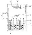
以下、本発明の第1実施形態について図を参照して説明する。図1(a)は、本発明の第1実施形態に係るSiC単結晶製造装置の断面構成を示したものである。この図に示されるように、SiC単結晶製造装置は、有底円筒状の容器本体1aと円形状の蓋体1bとによって構成されたグラファイト製の坩堝1を備えている。坩堝1内には、蓋体1bの裏面には台座2を介して例えば円形状のSiCの種結晶3が配置されている。(First embodiment)
Hereinafter, a first embodiment of the present invention will be described with reference to the drawings. Fig.1 (a) shows the cross-sectional structure of the SiC single crystal manufacturing apparatus based on 1st Embodiment of this invention. As shown in this figure, the SiC single crystal manufacturing apparatus includes a
上記容器本体1aの開口端部の外壁面には凹部1cが設けられている。そして、容器本体1aの凹部1cに蓋体1bの開口端部の内壁が接するように差し込まれると、図1(a)に示される形態となる。 A concave portion 1c is provided on the outer wall surface of the opening end of the
そして、図1(a)に示されるように、容器本体1a内に昇華ガスの供給源となるSiCの粉末原料4が配置されている。種結晶3と粉末原料4との間を成長空間領域5とすると、粉末原料4からの昇華ガスが成長空間領域5を通過して種結晶3の表面上に再結晶化して、種結晶3の表面にSiC単結晶が成長させられる構成とされている。なお、粉末原料4は、本発明の炭化珪素原料に相当する。 As shown in FIG. 1A, a SiC powder
さらに、坩堝1内には、中空円筒状の孔付パイプ10が配置されている。図1(b)は、当該孔付パイプ10の外観図である。この図に示されるように、孔付パイプ10は、円筒の外壁面から内壁面に貫通する小孔10aを有している。小孔10aのサイズは、容器本体1aに配置されるSiCの粉末原料4のSiC粒と同じ10〜1000μmのサイズである。後述するように、孔付パイプ10は粉末原料に差し込まれるため、小孔10aのサイズは当該小孔10aを介して孔付パイプ10の中空領域に粉末原料4が流入して中空領域が詰まらないようにするためにSiC粒よりも小さいサイズであることが好ましい。また、孔付パイプ10の外壁側から中空領域に粉末原料4の昇華ガスを通しやすくするため、小孔10aは高密度に設けられていることが好ましい。例えば、孔付パイプ10の外壁面に占める小孔10aの面積比率は、30〜80%ぐらいが望ましい。 Further, in the
このような孔付パイプ10の材質として、例えばカーボン材、タンタルやタングステン等の高融点金属が採用される。カーボン材については、ポーラス状態のものを採用することで、小孔10aを設ける必要がなく、孔付パイプ10の用意が容易になる。また、孔付パイプ10の内径および外径は、SiC単結晶の成長条件によって最適な値を選択することが可能である。例えば、孔付パイプ10の一端10b側の内径に対して他端10c側の内径を大きくすることができる。他方、坩堝1内に配置される場所に応じて、孔付パイプ10の内径や外径を決定しても良い。 As a material of such a
上記孔付パイプ10は、容器本体1a内に配置される粉末原料4に埋め込まれる。具体的には、図1(a)に示されるように、孔付パイプ10の一端10bが容器本体1aの底面側、他端10cが蓋体1b側に向く姿勢、すなわち坩堝1の中心軸に平行な姿勢とされている。さらに、孔付パイプ10の一端10bが粉末原料4の下層部まで埋め込まれ、他端10cが粉末原料4から突出している。この場合、孔付パイプ10の中空領域に粉末原料4は配置されず、粉末原料4は容器本体1aの内壁と孔付パイプ10に外壁との間に配置された状態となる。 The holed
また、孔付パイプ10の一端10bは、容器本体1aの底面に接触するように配置されるか、または、容器本体1aの底面から離されて配置される。孔付パイプ10の中空領域を介して粉末原料4から生じる昇華ガスをより多く成長空間領域5に導くため、孔付パイプ10の一端10bは容器本体1aの底面から離されていることが好ましい。孔付パイプ10の一端10bを粉末原料4に埋め込む深さは、粉末原料4の高さの半分以上にすることが望ましい。 Moreover, the
このように粉末原料4に埋め込まれる孔付パイプ10のパイプ数は、SiC単結晶の成長条件によって決定することができる。孔付パイプ10のパイプ数を多くすると、容器本体1a内に充填できる粉末原料4が減る一方、パイプ数を少なくすると容器本体1a内に充填できる粉末原料4は多くなる。なお、孔付パイプ10は、本発明の昇華ガス供給部材に相当する。以上が、本実施形態に係るSiC単結晶製造装置の坩堝1の全体構成である。 Thus, the number of pipes with
次に、上記SiC単結晶製造装置を用いてSiC単結晶を製造する方法について、図1および図2を参照して説明する。図2は、本実施形態におけるSiC単結晶の製造工程を示した図である。 Next, a method for producing a SiC single crystal using the SiC single crystal production apparatus will be described with reference to FIGS. FIG. 2 is a diagram showing a manufacturing process of the SiC single crystal in the present embodiment.
まず、図1(a)に示されるように、蓋体1bの底部に台座2を介して種結晶3を配置する。そして、当該種結晶3に対向するように、容器本体1a内に粉末原料4を配置し、当該粉末原料4に図1(b)に示される孔付パイプ10を埋め込む。この場合、先に容器本体1a内に孔付パイプ10を配置させた後、容器本体1a内に粉末原料4を配置させても良い。 First, as shown in FIG. 1A, a
続いて、坩堝1を図示しない加熱チャンバに設置し、図示しない排気機構を用いてガス排出を行うことで、坩堝1内を含めた外部チャンバ内を真空にし、位置が固定されたヒータの輻射熱により坩堝1を加熱することで坩堝1内を所定温度にする。このとき、ヒータで種結晶3と粉末原料4に温度差が発生させられる加熱を行えるようにしている。 Subsequently, the
種結晶3よりも粉末原料4の温度を高くするためにヒータは例えば粉末原料4に対向する位置に固定されている。 In order to make the temperature of the powder
加熱チャンバ内には例えば不活性ガス(Arガス等)や水素、結晶へのドーパントとなる窒素などの混合ガスを流入させる。この混合ガスは排気配管を介して排出される。種結晶3の成長面の温度およびSiC粉末原料4の温度を目標温度まで上昇させるまでは、加熱チャンバ内を大気圧に近い雰囲気圧力にして粉末原料4からの昇華を抑制し、目標温度になったところで、真空雰囲気とする。例えば、成長結晶を4H−SiCとする場合、粉末原料4の温度を2100〜2300℃とし、成長結晶表面の温度をそれよりも10〜200℃程度低くして、真空雰囲気を1.33〜6666Paとする。 For example, an inert gas (Ar gas or the like), hydrogen, or a mixed gas such as nitrogen serving as a dopant to the crystal is allowed to flow into the heating chamber. This mixed gas is discharged through an exhaust pipe. Until the temperature of the growth surface of the
このようにして、粉末原料4を加熱することで粉末原料4が昇華し、粉末原料4の表面から昇華ガスが発生する。この昇華ガスは、成長空間領域5内を通過して種結晶3に供給される。また、図1(a)に示されるように、粉末原料4内で発生した昇華ガスは、粉末原料4の深さにかかわらず、孔付パイプ10の小孔10aを介して孔付パイプ10の中空領域に流入し、当該中空領域を介して成長空間領域5に導かれる。したがって、昇華ガスは、粉末原料4の表面および孔付パイプ10から成長空間領域5に供給され、SiC単結晶20の成長に寄与する。 Thus, the powder
そして、粉末原料4を加熱し続けると、SiC粉末原料4の上層部のシリコンが枯渇してカーボン粒が固着したカーボン層すなわち枯渇層4aが形成される。この状態が維持されると昇華ガスの供給が低下する。これにより、粉末原料4の下部領域、特に加熱されにくい中央領域からの昇華ガスを枯渇層4aを経由して成長空間領域5に供給することは困難になる。 When the powder
しかしながら、図2に示されるように、粉末原料4の下層部で生じた昇華ガスは、枯渇層4aを経由せずに、孔付パイプ10の小孔10aを介して孔付パイプ10の中空領域に流入し、当該中空領域を通過して成長空間領域5に供給される。これにより、粉末原料4の上層部に枯渇層4aが形成されたとしても、孔付パイプ10を介して粉末原料4の下層部から昇華ガスを成長空間領域5に供給し続けることができる。このようにして、粉末原料4の下層部からも昇華ガスを安定して供給することができる。 However, as shown in FIG. 2, the sublimation gas generated in the lower layer portion of the powder
以上説明したように、本実施形態では、粉末原料4に孔付パイプ10を埋め込み、当該孔付パイプ10の中空領域に昇華ガスを通過させて成長空間領域5に供給することが特徴となっている。 As described above, the present embodiment is characterized in that the holed
これにより、粉末原料4の上層部に枯渇層4aが形成されたとしても、孔付パイプ10の中空領域を介して粉末原料4の下層部から昇華ガスを成長空間領域5に安定して供給し続けることができ、SiC単結晶20の成長速度が低下してしまうことを防止することができる。 As a result, even if the
また、粉末原料4の下層部からも安定して昇華ガスを供給し続けることができることから、SiC単結晶20を長時間成長させることができる。そして、孔付パイプ10を介して粉末原料4の下層部から成長空間領域5に昇華ガスを導くことができるので、下層部の粉末原料4が無駄にならず、未昇華の粉末原料4が残留しないようにすることができる。 Further, since the sublimation gas can be continuously supplied from the lower layer portion of the powder
(第2実施形態)
本実施形態では、第1実施形態と異なる部分についてのみ説明する。図3は、本発明の第2実施形態に係るSiC単結晶製造装置の断面構成図である。この図に示されるように、本実施形態では、図1(b)に示される孔付パイプ10は坩堝1の中心軸に平行に配置されると共に坩堝1の径方向にも配置され、これらが格子状に立体的に組まれている。(Second Embodiment)
In the present embodiment, only different parts from the first embodiment will be described. FIG. 3 is a cross-sectional configuration diagram of an SiC single crystal manufacturing apparatus according to the second embodiment of the present invention. As shown in this figure, in this embodiment, the
すなわち、坩堝1の中心軸が延びる方向に沿って配置される孔付パイプ10と、坩堝1の中心軸に垂直な面において一方向に延びる方向にそって配置される孔付パイプ10とがジャングルジム状に組み合わされている。そして、孔付パイプ10のうち中心軸に平行に配置されるものの一端が粉末原料4から突出するように、格子状の孔付パイプ10が粉末原料4に埋め込まれている。 That is, the holed
このように、孔付パイプ10を立体格子状に組むことで、孔付パイプ10と粉末原料4との接触面積を増やすことができる。すなわち、成長空間領域5への昇華ガスの供給効率を向上させることができる。 Thus, the contact area of the
また、孔付パイプ10が一定間隔で立体的に組まれることで、各孔付パイプ10の中空領域に流入する昇華ガスの量を均等にすることができ、ひいては坩堝1の中心軸に平行に配置される各孔付パイプ10から成長空間領域5に均等に昇華ガスを供給することができる。 In addition, since the
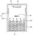
(第3実施形態)
本実施形態では、第1実施形態と異なる部分についてのみ説明する。図4は、本発明の第3実施形態に係るSiC単結晶製造装置の断面構成図である。この図に示されるように、本実施形態では、容器本体1aの底に昇華ガス供給容器30が配置されている。(Third embodiment)
In the present embodiment, only different parts from the first embodiment will be described. FIG. 4 is a cross-sectional configuration diagram of an SiC single crystal manufacturing apparatus according to the third embodiment of the present invention. As shown in this figure, in this embodiment, a sublimation
図5(a)は昇華ガス供給容器30の斜視図、図5(b)は蓋体1bから容器本体1a側に見た平面図、図5(c)は坩堝1の中心軸に平行な昇華ガス供給容器30の断面図である。 5 (a) is a perspective view of the sublimation
昇華ガス供給容器30は有底円筒状をなしており、当該容器の内壁31と外壁32との間に空間33を有している。また、少なくとも昇華ガス供給容器30の内壁31に、図1(b)に示される小孔10aと同様の小孔34が多数設けられている。これら小孔34は、昇華ガスを空間33に流入させるための通路としての役割を果たす。 The sublimation
また、図4および図5(a)に示されるように、昇華ガス供給容器30の内壁31で囲まれた領域に粉末原料4が配置される。これにより、図5(b)に示されるように、昇華ガス供給容器30は坩堝1の容器本体1aと粉末原料4とに挟まれた状態となる。 Further, as shown in FIGS. 4 and 5A, the powder
すなわち、昇華ガス供給容器30は、粉末原料4の容器として機能する一方、粉末原料4から生じた昇華ガスを、小孔34を介して空間33に導き、昇華ガス供給容器30の開口端35から成長空間領域5に導く機能を有する。 In other words, the sublimation
上記昇華ガス供給容器30として、例えばカーボン材、または高融点材料が採用される。なお、昇華ガス供給容器30として、ポーラス材を採用しても良い。また、粉末原料4の加熱効率は劣化するが断熱材を採用しても良い。 As the sublimation
次に、上記SiC単結晶製造装置を用いてSiC単結晶を製造する方法について説明する。まず、図5に示される昇華ガス供給容器30を坩堝1の容器本体1aに配置し、さらに内壁31で囲まれた領域に粉末原料4を配置する。 Next, a method for producing a SiC single crystal using the SiC single crystal production apparatus will be described. First, the sublimation
続いて、第1実施形態と同様に、坩堝1を加熱していくと、粉末原料4の表面から昇華ガスが成長空間領域5に供給され、種結晶3の上にSiC単結晶20が成長していく。 Subsequently, as in the first embodiment, when the
そして、粉末原料4の上層部のSiが枯渇して枯渇層が形成される。しかしながら、粉末原料4の下層部で生じた昇華ガスは、昇華ガス供給容器30の小孔34を介して昇華ガス供給容器30の空間33内に導かれ、当該空間33を通過して開口端35から成長空間領域5に供給される。したがって、SiC単結晶20が継続して成長していく。 And Si of the upper layer part of the powder
以上のように、粉末原料4の上層部からの昇華ガスの供給が終了したとしても、粉末原料4の下層部から生じる昇華ガスを、昇華ガス供給容器30を介して成長空間領域5に供給することができる。 As described above, even if the supply of the sublimation gas from the upper layer portion of the powder
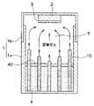
(第4実施形態)
本実施形態では、第1実施形態と異なる部分についてのみ説明する。図6は、本発明の第4実施形態に係るSiC単結晶製造装置の断面構成図である。この図に示されるように、容器本体1a内に配置される孔付パイプ10の長さがそれぞれ異なっている。言い換えると、容器本体1aの底面から孔付パイプ10の他端までの高さが異なっている。これにより、粉末原料4の表面から突出する孔付パイプ10の他端の高さが異なることになる。(Fourth embodiment)
In the present embodiment, only different parts from the first embodiment will be described. FIG. 6 is a cross-sectional configuration diagram of an SiC single crystal manufacturing apparatus according to the fourth embodiment of the present invention. As shown in this figure, the lengths of the
具体的には、坩堝1の中心軸上に配置される孔付パイプ10の長さがもっとも短く、坩堝1の中心軸から径方向に遠ざかるほど孔付パイプ10の長さが長くなっている。孔付パイプ10が長くなるということは、成長空間領域5に露出する粉末原料4の表面からの昇華ガスの供給口が高くなることを指し、より種結晶3、SiC単結晶20に近い場所に昇華ガスが供給されることを示している。 Specifically, the length of the holed
このように、坩堝1内に配置される場所に応じて坩堝1の軸方向の長さが異なる各孔付パイプ10においては、粉末原料4から突出した部分に小孔10aを設ける必要はない。また、坩堝1内に配置される場所に応じて、孔付パイプ10の太さ、すなわち内径および外径を設定することができる。例えば、成長空間領域5への昇華ガスの供給量を増やしたい場合、孔付パイプ10の径を太くすれば良い。 Thus, in each
次に、上記SiC単結晶製造装置を用いてSiC単結晶を製造する方法について説明する。まず、図6に示されるように、長さが異なる孔付パイプ10を用意する。そして、容器本体1a内に、坩堝1の中心軸から遠ざかるほど長い孔付パイプ10を配置する。さらに、容器本体1a内に粉末原料4を配置する。これにより、坩堝1の中心軸から遠ざかるほど粉末原料4から突出する孔付パイプ10の高さが高くなる。 Next, a method for producing a SiC single crystal using the SiC single crystal production apparatus will be described. First, as shown in FIG. 6,
続いて、第1実施形態と同様に、坩堝1を加熱チャンバに設置して坩堝1を加熱する。これにより、容器本体1a内の粉末原料4が加熱されて昇華し、昇華ガスが粉末原料4の表面から成長空間領域5に供給される。 Subsequently, as in the first embodiment, the
また、第1実施形態と同様に、粉末原料4の下層部から生じた昇華ガスが各孔付パイプ10の小孔10aを介して各孔付パイプ10の中空領域に流入し、当該中空領域を通過して成長空間領域5に供給される。 Further, as in the first embodiment, the sublimation gas generated from the lower layer portion of the powder
この場合、上述のように、坩堝1内の場所に応じて孔付パイプ10の長さが異なっている。特に、坩堝1の中心軸から離れるほど孔付パイプ10が長いため、種結晶3の近傍では、坩堝1の外周から中心軸に向かう昇華ガスの流れが作られる。これにより、種結晶3の上にSiC単結晶20の均等な成長、すなわち種結晶3表面と平行にフラットな成長ができるようにする。 In this case, as described above, the length of the holed
この後、粉末原料4の上層部に枯渇層4aが形成されたとしても、第1実施形態と同様に、孔付パイプ10によって粉末原料4の下層部から生じた昇華ガスを成長空間領域5に供給することができる。 Thereafter, even if the
なお、孔付パイプ10の長さや配置によっては、種結晶3の近傍で坩堝1の中心軸から坩堝1の外周方向に向かう昇華ガスの流れを作ることもできる。 Depending on the length and arrangement of the holed
以上説明したように、坩堝1内に配置する場所に応じて少なくとも孔付パイプ10の長さが異なるようにすることで、成長空間領域5における孔付パイプ10の昇華ガス供給口の位置を変更することができる。これにより、成長空間領域5において結晶成長に良好な昇華ガスの流れを作ることができる。 As described above, the position of the sublimation gas supply port of the
(第5実施形態)
本実施形態では、第4実施形態と異なる部分についてのみ説明する。図7は、本発明の第5実施形態に係るSiC単結晶製造装置の断面構成図である。この図に示されるように、坩堝1内のうちもっとも外側に配置された孔付パイプ10は、一端が粉末原料4に埋め込まれ、粉末原料4から突出した他端が坩堝1の中心軸側に折り曲げられた形態となっている。折り曲げる角度は種結晶3、あるいは成長中の結晶表面上で、成長速度が遅い領域に昇華ガスがより多く供給されるような角度に設定することが望ましい。このように、他端が折り曲げられた孔付パイプ10から成長空間領域5に供給される昇華ガスの供給口の位置を変更することができる。(Fifth embodiment)
In the present embodiment, only parts different from the fourth embodiment will be described. FIG. 7 is a cross-sectional configuration diagram of an SiC single crystal manufacturing apparatus according to the fifth embodiment of the present invention. As shown in this figure, the holed
(第6実施形態)
本実施形態では、第4実施形態と異なる部分についてのみ説明する。上記第4実施形態では、孔付パイプ10の長さを異ならせることで、成長空間領域5に昇華ガスの流れを作っていたが、本実施形態では、さらに粉末原料4の表面に蓋をすることが特徴となっている。(Sixth embodiment)
In the present embodiment, only parts different from the fourth embodiment will be described. In the fourth embodiment, the flow of sublimation gas is created in the
図8は、本発明の第6実施形態に係るSiC単結晶製造装置の断面構成図である。この図に示されるように、坩堝1の容器本体1a内に配置された粉末原料4の表面に円形および板状をなす原料蓋40が配置されている。原料蓋40の径は、容器本体1aの内径と同じになっており、原料蓋40の側面が容器本体1aの内壁面に接するようになっている。 FIG. 8 is a cross-sectional configuration diagram of an SiC single crystal manufacturing apparatus according to the sixth embodiment of the present invention. As shown in this figure, a
また、原料蓋40には各孔付パイプ10が差し込まれる貫通孔が多数設けられており、各貫通孔に各孔付パイプ10が差し込まれている。また、原料蓋40は、粉末原料4の表面に接触するように配置される。これにより、粉末原料4は成長空間領域5に露出しない状態となっている。このような原料蓋40の材質として、カーボンやタンタルが採用される。 The
この原料蓋40を坩堝1内に配置して坩堝1を加熱すると、昇華ガスは原料蓋40によって成長空間領域5に直接供給されなくなる。すなわち、昇華ガスは、各孔付パイプ10の小孔10aを介して各孔付パイプ10の中空領域に流入し、孔付パイプ10内を通過して成長空間領域5に供給される。つまり、昇華ガスは、各孔付パイプ10のみから成長空間領域5に供給される。 When the
以上説明したように、粉末原料4の上に原料蓋40を配置し、粉末原料4から生じる昇華ガスを孔付パイプ10のみによって成長空間領域5に供給することで、種結晶3付近に良好な昇華ガスの流れを作ることができる。この場合、原料蓋40から突出する孔付パイプ10の高さを変更することや、孔付パイプ10の昇華ガスの供給口の向きを調整すること等によって、さらに良好な昇華ガスの流れを作ることができる。 As described above, the
そして、孔付パイプ10を経由せずに、粉末原料4の表面から成長空間領域5に直接供給される昇華ガスはなくなる。これにより、Siが抜けた枯渇層4aからカーボン粒子が飛散してSiC単結晶20に取り込まれることを防止することができ、ひいてはSiC単結晶20の結晶欠陥を抑制することができる。 And the sublimation gas supplied directly from the surface of the powder
(第7実施形態)
本実施形態では、第6実施形態と異なる部分についてのみ説明する。図7は、本発明の第7実施形態に係るSiC単結晶製造装置の断面構成図である。この図に示されるように、本実施形態では、原料蓋40が粉末原料4の表面から離されて配置されている。(Seventh embodiment)
In the present embodiment, only parts different from the sixth embodiment will be described. FIG. 7 is a cross-sectional configuration diagram of an SiC single crystal manufacturing apparatus according to a seventh embodiment of the present invention. As shown in this figure, in the present embodiment, the
これによると、坩堝1を加熱することで、粉末原料4の表面と原料蓋40との間の空間に昇華ガスが供給される。この昇華ガスは、粉末原料4の表面と原料蓋40との間の空間に露出する各孔付パイプ10の小孔10aを介して各孔付パイプ10内に流入し、各孔付パイプ10内を通過して成長空間領域5に供給される。 According to this, the sublimation gas is supplied to the space between the surface of the powder
このように、坩堝1内に原料蓋40を配置したとしても、当該原料蓋40を粉末原料4に接触しないように配置することで、粉末原料4の表面から昇華ガスを生じさせることができる。これにより、成長空間領域5への昇華ガスの供給効率を向上させることができる。 Thus, even if the
この場合、各孔付パイプ10において、原料蓋40と粉末原料4の表面の間に配置される各小孔10aを大きくする、あるいは高密度にすることで、原料蓋40と粉末原料4の表面の間の昇華ガスをより多く孔付パイプ10内に導くことができる。 In this case, in each
(第8実施形態)
本実施形態では、第7実施形態と異なる部分についてのみ説明する。図10は、本発明の第8実施形態に係るSiC単結晶製造装置の断面構成図である。この図に示されるように、原料蓋40と粉末原料4の表面の間に位置する各孔付パイプ10が分割されている。すなわち、各孔付パイプ10は、粉末原料4に埋め込まれる第1孔付パイプ11と、一端が原料蓋40に固定され他端が成長空間領域5に配置される第2孔付パイプ12とによってそれぞれ構成されている。(Eighth embodiment)
In the present embodiment, only parts different from the seventh embodiment will be described. FIG. 10 is a cross-sectional configuration diagram of an SiC single crystal manufacturing apparatus according to the eighth embodiment of the present invention. As shown in this figure, each
なお、第1孔付パイプ11は本発明の第1昇華ガス供給部材に相当し、第2孔付パイプ12は本発明の第2昇華ガス供給部材に相当する。 The first holed
これによると、粉末原料4の表面から原料蓋40と粉末原料4の表面の間に供給された昇華ガスは、原料蓋40に固定された各第2孔付パイプ12の一端から各第2孔付パイプ12内に流入し、他端から成長空間領域5に供給される。すなわち、昇華ガスは、第7実施形態のように小孔10aを介することなく各第2孔付パイプ12内に流入するため、原料蓋40と粉末原料4の表面の間に供給された昇華ガスの成長空間領域5への供給効率を向上させることができる。 According to this, the sublimation gas supplied from the surface of the powder
なお、第2孔付パイプ12は小孔10aが設けられていなくても良い。また、第1孔付パイプ11と第2孔付パイプ12とが一直線上にそれぞれ配置されていなくても良い。 The second holed
(第9実施形態)
本実施形態では、上記各実施形態と異なる部分についてのみ説明する。図11(a)は本実施形態に係るSiC単結晶製造装置の断面構成図、(b)は種結晶3側から粉末原料4側を見た図である。(Ninth embodiment)
In the present embodiment, only different portions from the above embodiments will be described. FIG. 11A is a cross-sectional configuration diagram of the SiC single crystal manufacturing apparatus according to the present embodiment, and FIG.
図11に示したように、口径が異なる2つの第1、第2孔付パイプ51、52を、各孔付パイプ51、52の径中心が坩堝1の中心軸に一致するように容器本体1a内に設置する。第1孔付パイプ51は第2孔付パイプ52よりも径が大きくなっており、第1孔付パイプ51の中空部分に第2孔付パイプ52が配置されると、第1孔付パイプ51の内壁と第2孔付パイプ52の外壁とで空間が形成される。これら各孔付パイプ51、52は、図1(b)に示されるように、多数の小孔10aを備えたものである。 As shown in FIG. 11, two first and
そして、各孔付パイプ51、52の一端を粉末原料4下部に埋め込み、他端を粉末原料4から突出させることで、2つの孔付パイプ51、52で形成された空間を成長空間領域5に開口させる。これにより、粉末原料4の下部領域の昇華ガスは、孔付パイプ51、52を貫通して各孔付パイプ51、52の間の空間領域に流入し、成長空間領域5に供給される。 Then, by embedding one end of each of the
径の中心位置を同じにして設置される孔付パイプ51、52は2つに限らず、3つ以上を設置してもよい。また、空間ができるのであれば、孔付パイプの中心を一致させる必要はない。また、孔付パイプ51、52の径中心を坩堝1の中心軸に合わせる必要もない。 The number of the
以上のように、径の異なる孔付パイプ51、52を容器本体1a内に設置し、容器本体1aの壁面と第1孔付パイプ51との間、第2孔付パイプ52の中空部分の間に粉末原料4を配置する。これにより、各孔付パイプ51、52の径の違いによって形成される空間を介して、成長空間領域5に昇華ガスを供給することができる。 As described above, the holed
(他の実施形態)
上記各実施形態では、孔付パイプ10は中空円筒状になっているが、これは一例を示すものであって、円筒状に限らず、他の筒状の孔付パイプ10を採用することもできる。(Other embodiments)
In each of the above embodiments, the holed
第1実施形態では、孔付パイプ10は坩堝1の中心軸に平行になるように粉末原料4に埋め込まれていたが、孔付パイプ10は、坩堝1の中心軸に対して傾けられて粉末原料4に埋め込まれていても良い。 In the first embodiment, the holed
第4実施形態では、坩堝1の中心軸から径方向に離れるほど孔付パイプ10が長くされていたが、これは一例を示すものであって、昇華ガスの流れを作る上で自由に変更可能であることは言うまでもない。 In the fourth embodiment, the
第5実施形態では、坩堝1内のうちもっとも外側に配置された孔付パイプ10の他端が坩堝1の中心軸側に直角に折り曲げられたものが示されているが、これは一例を示すものであって、他の場所に配置された孔付パイプ10の他端が折り曲げられていても良い。また、孔付パイプ10の他端を折り曲げる角度や向きも自由に設定可能である。 In the fifth embodiment, the other end of the
各実施形態を相互に組み合わせた実施を行うこともできる。例えば、第6実施形態に示される原料蓋40を、第1実施形態や第2実施形態に採用することができる。また、第4〜第8実施形態において、粉末原料4に埋め込まれる孔付パイプ10を第2実施形態に示される立体格子状にすることも可能である。 It is also possible to carry out an embodiment in which the embodiments are combined with each other. For example, the
1…坩堝、1a…容器本体、1b…蓋体、3…種結晶、4…SiC粉末原料、10…孔付パイプ、10a…孔付パイプの小孔、11…第1孔付パイプ、12…第2孔付パイプ、20…SiC単結晶、30…昇華ガス供給容器、31…内壁、32…外壁、33…空間、34…昇華ガス供給容器の小孔、40…原料蓋、51…第1孔付パイプ、52…第2孔付パイプ。 DESCRIPTION OF
Claims (18)
Translated fromJapanese中空筒状であって、筒の外壁面から内壁面に貫通する複数の小孔(10a)を備え、前記筒の一端(10b)が前記炭化珪素原料(4)に埋め込まれ、前記筒の他端(10c)が前記炭化珪素原料(4)から突出するように前記容器本体(1a)内に配置される昇華ガス供給部材(10)を有し、
前記昇華ガス供給部材(10)は、前記容器本体(1a)内に複数配置されていることを特徴とする炭化珪素単結晶の製造装置。A hollow cylindrical crucible (1) having a bottomed cylindrical container body (1a) and a lid (1b) for closing the container body (1a); By disposing a seed crystal (3) made of a silicon carbide substrate in 1b) and disposing a silicon carbide raw material (4) in the container body (1a) and supplying a sublimation gas of the silicon carbide raw material (4), In the silicon carbide single crystal manufacturing apparatus for growing the silicon carbide single crystal (20) on the seed crystal (3),
A hollow cylinder having a plurality of small holes (10a) penetrating from the outer wall surface of the cylinder to the inner wall surface, one end (10b) of the cylinder being embedded in the silicon carbide raw material (4),have a end sublimation gas supply member (10c) is disposed in the container body (1a) in so as to protrude from the silicon carbide source material (4)(10),
An apparatus for producing a silicon carbide single crystal, wherein a plurality of the sublimation gas supply members (10) are arranged in the container body (1a) .
中空筒状であって、筒の外壁面から内壁面に貫通する複数の小孔(10a)を備え、前記筒の一端(10b)が前記炭化珪素原料(4)に埋め込まれ、前記筒の他端(10c)が前記炭化珪素原料(4)から突出するように前記容器本体(1a)内に配置される昇華ガス供給部材(10)を有し、
前記昇華ガス供給部材(10)は、前記炭化珪素原料(4)に埋め込まれる部分が立体格子状をなしていることを特徴とする炭化珪素単結晶の製造装置。A hollow cylindrical crucible (1) having a bottomed cylindrical container body (1a) and a lid (1b) for closing the container body (1a); By disposing a seed crystal (3) made of a silicon carbide substrate in 1b) and disposing a silicon carbide raw material (4) in the container body (1a) and supplying a sublimation gas of the silicon carbide raw material (4), In the silicon carbide single crystal manufacturing apparatus for growing the silicon carbide single crystal (20) on the seed crystal (3),
A hollow cylinder having a plurality of small holes (10a) penetrating from the outer wall surface of the cylinder to the inner wall surface, one end (10b) of the cylinder being embedded in the silicon carbide raw material (4), A sublimation gas supply member (10) disposed in the container body (1a) such that an end (10c) protrudes from the silicon carbide raw material (4);
The sublimation gas supply member (10), said silicon carbide source material (4) portion manufacturing apparatus tothat carbonization silicon single crystal, characterized in that it forms a three-dimensional lattice-like embedded in.
中空筒状であって、筒の外壁面から内壁面に貫通する複数の小孔(10a)を備え、前記筒の一端(10b)が前記炭化珪素原料(4)に埋め込まれ、前記筒の他端(10c)が前記炭化珪素原料(4)から突出するように前記容器本体(1a)内に配置される昇華ガス供給部材(10)を有し、
円形および板状であって、前記容器本体(1a)の内径と同じ径、あるいは前記容器本体(1a)の内径以下であり、前記板の一面側に前記昇華ガス供給部材(10)の一端が位置し、前記板の他面側に前記昇華ガス供給部材(10)の他端が位置するように前記板に前記昇華ガス供給部材(10)が差し込まれると共に、前記炭化珪素原料(4)の表面に接触するように配置される原料蓋(40)が備えられていることを特徴とする炭化珪素単結晶の製造装置。A hollow cylindrical crucible (1) having a bottomed cylindrical container body (1a) and a lid (1b) for closing the container body (1a); By disposing a seed crystal (3) made of a silicon carbide substrate in 1b) and disposing a silicon carbide raw material (4) in the container body (1a) and supplying a sublimation gas of the silicon carbide raw material (4), In the silicon carbide single crystal manufacturing apparatus for growing the silicon carbide single crystal (20) on the seed crystal (3),
A hollow cylinder having a plurality of small holes (10a) penetrating from the outer wall surface of the cylinder to the inner wall surface, one end (10b) of the cylinder being embedded in the silicon carbide raw material (4), A sublimation gas supply member (10) disposed in the container body (1a) such that an end (10c) protrudes from the silicon carbide raw material (4);
It is circular and plate-shaped and has the same diameter as the inner diameter of the container main body (1a) or less than the inner diameter of the container main body (1a), and one end of the sublimation gas supply member (10) is provided on one side of the plate The sublimation gas supply member (10) is inserted into the plate so that the other end of the sublimation gas supply member (10) is positioned on the other surface side of the plate, and the silicon carbide raw material (4) apparatus for producingcarbonization silicon single crystalyou characterized in that raw material lid is positioned to contact the surface (40) is provided.
中空筒状であって、筒の外壁面から内壁面に貫通する複数の小孔(10a)を備え、前記筒の一端(10b)が前記炭化珪素原料(4)に埋め込まれ、前記筒の他端(10c)が前記炭化珪素原料(4)から突出するように前記容器本体(1a)内に配置される昇華ガス供給部材(10)を有し、
円形および板状であって、前記容器本体(1a)の内径と同じ径、あるいは前記容器本体(1a)の内径以下であり、前記板の一面側に前記昇華ガス供給部材(10)の一端が位置し、前記板の他面側に前記昇華ガス供給部材(10)の他端が位置するように前記板に前記昇華ガス供給部材(10)が差し込まれると共に、前記炭化珪素原料(4)の表面から離されて配置される原料蓋(40)が備えられていることを特徴とする炭化珪素単結晶の製造装置。A hollow cylindrical crucible (1) having a bottomed cylindrical container body (1a) and a lid (1b) for closing the container body (1a); By disposing a seed crystal (3) made of a silicon carbide substrate in 1b) and disposing a silicon carbide raw material (4) in the container body (1a) and supplying a sublimation gas of the silicon carbide raw material (4), In the silicon carbide single crystal manufacturing apparatus for growing the silicon carbide single crystal (20) on the seed crystal (3),
A hollow cylinder having a plurality of small holes (10a) penetrating from the outer wall surface of the cylinder to the inner wall surface, one end (10b) of the cylinder being embedded in the silicon carbide raw material (4), A sublimation gas supply member (10) disposed in the container body (1a) such that an end (10c) protrudes from the silicon carbide raw material (4);
It is circular and plate-shaped and has the same diameter as the inner diameter of the container main body (1a) or less than the inner diameter of the container main body (1a), and one end of the sublimation gas supply member (10) is provided on one side of the plate The sublimation gas supply member (10) is inserted into the plate so that the other end of the sublimation gas supply member (10) is positioned on the other surface side of the plate, and the silicon carbide raw material (4) apparatus for producingcarbonization silicon single crystalyou characterized in that raw material lid is arranged spaced from the surface (40) is provided.
有底円筒状であって、前記容器本体(1a)内に配置されるものであり、前記有底円筒の内壁(31)と外壁(32)との間に空間(33)を有し、前記空間(33)は前記有底円筒の開口端(35)を介して成長空間領域(5)と繋がっていると共に、少なくとも前記内壁(31)に当該内壁(31)を貫通する小孔(34)が複数設けられており、前記内壁(31)の内側に前記炭化珪素原料(4)が配置される昇華ガス供給容器(30)を有することを特徴とする炭化珪素単結晶の製造装置。A hollow cylindrical crucible (1) having a bottomed cylindrical container body (1a) and a lid (1b) for closing the container body (1a); By disposing a seed crystal (3) made of a silicon carbide substrate in 1b) and disposing a silicon carbide raw material (4) in the container body (1a) and supplying a sublimation gas of the silicon carbide raw material (4), In the silicon carbide single crystal manufacturing apparatus for growing the silicon carbide single crystal (20) on the seed crystal (3),
The bottomed cylinder is disposed in the container body (1a), and has a space (33) between the inner wall (31) and the outer wall (32) of the bottomed cylinder, The space (33) is connected to the growth space region (5) via the open end (35) of the bottomed cylinder, and at least a small hole (34) penetrating the inner wall (31) through the inner wall (31). And a sublimation gas supply container (30) in which the silicon carbide raw material (4) is disposed inside the inner wall (31).
中空筒状であって、筒の外壁面から内壁面に貫通する複数の小孔(10a)を備え、前記筒の一端が前記炭化珪素原料(4)に埋め込まれ、前記筒の他端が前記炭化珪素原料(4)から突出するように前記容器本体(1a)内に配置される第1昇華ガス供給部材(51)および第2昇華ガス供給部材(52)を有し、
前記第1昇華ガス供給部材(51)は前記第2昇華ガス供給部材(52)よりも径が大きくなっており、前記第1昇華ガス供給部材(51)の中空部分に前記第2昇華ガス供給部材(52)が配置されており、
前記炭化珪素原料(4)は、前記容器本体(1a)と前記第1昇華ガス供給部材(51)との間、および前記第2昇華ガス供給部材(52)の中空部分に配置されるようになっていることを特徴とする炭化珪素単結晶の製造装置。A hollow cylindrical crucible (1) having a bottomed cylindrical container body (1a) and a lid (1b) for closing the container body (1a); By disposing a seed crystal (3) made of a silicon carbide substrate in 1b) and disposing a silicon carbide raw material (4) in the container body (1a) and supplying a sublimation gas of the silicon carbide raw material (4), In the silicon carbide single crystal manufacturing apparatus for growing the silicon carbide single crystal (20) on the seed crystal (3),
A hollow cylinder having a plurality of small holes (10a) penetrating from the outer wall surface to the inner wall surface, one end of the tube being embedded in the silicon carbide raw material (4), and the other end of the tube being the A first sublimation gas supply member (51) and a second sublimation gas supply member (52) disposed in the container body (1a) so as to protrude from the silicon carbide raw material (4);
The first sublimation gas supply member (51) has a diameter larger than that of the second sublimation gas supply member (52), and the second sublimation gas supply to a hollow portion of the first sublimation gas supply member (51). A member (52) is disposed;
The silicon carbide raw material (4) is disposed between the container body (1a) and the first sublimation gas supply member (51) and in a hollow portion of the second sublimation gas supply member (52). An apparatus for producing a silicon carbide single crystal, wherein
中空筒状であって、前記筒の外壁面から内壁面に貫通する複数の小孔(10a)を備えた昇華ガス供給部材(10)を用意し、前記昇華ガス供給部材(10)を前記容器本体(1a)内に複数配置し、当該昇華ガス供給部材(10)の一端を前記炭化珪素原料(4)に埋め込み、当該昇華ガス供給部材(10)の他端を前記炭化珪素原料(4)から突出させた状態で前記坩堝(1)を加熱することを特徴とする炭化珪素単結晶の製造方法。A hollow cylindrical crucible (1) having a bottomed cylindrical container body (1a) and a lid (1b) for closing the container body (1a); By disposing a seed crystal (3) made of a silicon carbide substrate in 1b) and disposing a silicon carbide raw material (4) in the container body (1a) and supplying a sublimation gas of the silicon carbide raw material (4), In the method for producing a silicon carbide single crystal in which a silicon carbide single crystal (20) is grown on the seed crystal (3),
A sublimation gas supply member (10) having a hollow cylindrical shape and having a plurality of small holes (10a) penetrating from an outer wall surface to an inner wall surface of the cylinder is prepared, and thesublimation gas supply member (10) is placed in the container A plurality of sublimation gas supply members (10) are embedded in themain body (1a), one end of the sublimation gas supply member (10) is embedded in the silicon carbide raw material (4), and the other end of the sublimation gas supply member (10) is embedded in the silicon carbide raw material (4). A method for producing a silicon carbide single crystal, wherein the crucible (1) is heated in a state of protruding from a silicon carbide.
中空筒状であって、前記筒の外壁面から内壁面に貫通する複数の小孔(10a)を備えた昇華ガス供給部材(10)を用意し、当該昇華ガス供給部材(10)の一端を前記炭化珪素原料(4)に埋め込み、当該昇華ガス供給部材(10)の他端を前記炭化珪素原料(4)から突出させた状態で前記坩堝(1)を加熱し、
前記昇華ガス供給部材(10)として、前記炭化珪素原料(4)に埋め込まれる部分が立体格子状をなしているものを用意することを特徴とする炭化珪素単結晶の製造方法。A hollow cylindrical crucible (1) having a bottomed cylindrical container body (1a) and a lid (1b) for closing the container body (1a); By disposing a seed crystal (3) made of a silicon carbide substrate in 1b) and disposing a silicon carbide raw material (4) in the container body (1a) and supplying a sublimation gas of the silicon carbide raw material (4), In the method for producing a silicon carbide single crystal in which a silicon carbide single crystal (20) is grown on the seed crystal (3),
A sublimation gas supply member (10) having a hollow cylindrical shape and having a plurality of small holes (10a) penetrating from the outer wall surface to the inner wall surface of the cylinder is prepared, and one end of the sublimation gas supply member (10) is provided. The crucible (1) is heated while being embedded in the silicon carbide raw material (4) and the other end of the sublimation gas supply member (10) is protruded from the silicon carbide raw material (4).
Examples sublimation gas supply member (10), the manufacturing method of tothat carbonization silicon single crystal, characterized in that the part embedded in the silicon carbide source material (4) is prepared which forms a three-dimensional lattice.
中空筒状であって、前記筒の外壁面から内壁面に貫通する複数の小孔(10a)を備えた昇華ガス供給部材(10)を用意し、当該昇華ガス供給部材(10)の一端を前記炭化珪素原料(4)に埋め込み、当該昇華ガス供給部材(10)の他端を前記炭化珪素原料(4)から突出させた状態で前記坩堝(1)を加熱し、
円形および板状であって、前記容器本体(1a)の内径と同じ径、あるいは前記容器本体(1a)の内径以下である原料蓋(40)を用意し、前記原料蓋(40)の一面側に前記昇華ガス供給部材(10)の一端が位置し、前記板の他面側に前記昇華ガス供給部材(10)の他端が位置するように前記原料蓋(40)に前記昇華ガス供給部材(10)を差し込むと共に、前記炭化珪素原料(4)の表面に接触するように配置した状態で前記坩堝(1)を加熱することを特徴とする炭化珪素単結晶の製造方法。A hollow cylindrical crucible (1) having a bottomed cylindrical container body (1a) and a lid (1b) for closing the container body (1a); By disposing a seed crystal (3) made of a silicon carbide substrate in 1b) and disposing a silicon carbide raw material (4) in the container body (1a) and supplying a sublimation gas of the silicon carbide raw material (4), In the method for producing a silicon carbide single crystal in which a silicon carbide single crystal (20) is grown on the seed crystal (3),
A sublimation gas supply member (10) having a hollow cylindrical shape and having a plurality of small holes (10a) penetrating from the outer wall surface to the inner wall surface of the cylinder is prepared, and one end of the sublimation gas supply member (10) is provided. The crucible (1) is heated while being embedded in the silicon carbide raw material (4) and the other end of the sublimation gas supply member (10) is protruded from the silicon carbide raw material (4).
A raw material lid (40) having a circular shape and a plate shape and having the same diameter as the inner diameter of the container main body (1a) or less than the inner diameter of the container main body (1a) is prepared. The sublimation gas supply member (10) is positioned at one end of the sublimation gas supply member (10), and the other end of the sublimation gas supply member (10) is positioned at the other side of the plate. (10) with plugging, the manufacturing method of tothat carbonization silicon single crystal comprising the step of heating said crucible (1) in the arrangement state in contact with the surface of the silicon carbide source material (4).
中空筒状であって、前記筒の外壁面から内壁面に貫通する複数の小孔(10a)を備えた昇華ガス供給部材(10)を用意し、当該昇華ガス供給部材(10)の一端を前記炭化珪素原料(4)に埋め込み、当該昇華ガス供給部材(10)の他端を前記炭化珪素原料(4)から突出させた状態で前記坩堝(1)を加熱し、
円形および板状であって、前記容器本体(1a)の内径と同じ径、あるいは前記容器本体(1a)の内径以下である原料蓋(40)を用意し、前記原料蓋(40)の一面側に前記昇華ガス供給部材(10)の一端が位置し、前記板の他面側に前記昇華ガス供給部材(10)の他端が位置するように前記原料蓋(40)に前記昇華ガス供給部材(10)を差し込むと共に、前記炭化珪素原料(4)の表面から離して配置した状態で前記坩堝(1)を加熱することを特徴とする炭化珪素単結晶の製造方法。A hollow cylindrical crucible (1) having a bottomed cylindrical container body (1a) and a lid (1b) for closing the container body (1a); By disposing a seed crystal (3) made of a silicon carbide substrate in 1b) and disposing a silicon carbide raw material (4) in the container body (1a) and supplying a sublimation gas of the silicon carbide raw material (4), In the method for producing a silicon carbide single crystal in which a silicon carbide single crystal (20) is grown on the seed crystal (3),
A sublimation gas supply member (10) having a hollow cylindrical shape and having a plurality of small holes (10a) penetrating from the outer wall surface to the inner wall surface of the cylinder is prepared, and one end of the sublimation gas supply member (10) is provided. The crucible (1) is heated while being embedded in the silicon carbide raw material (4) and the other end of the sublimation gas supply member (10) is protruded from the silicon carbide raw material (4).
A raw material lid (40) having a circular shape and a plate shape and having the same diameter as the inner diameter of the container main body (1a) or less than the inner diameter of the container main body (1a) is prepared. The sublimation gas supply member (10) is positioned at one end of the sublimation gas supply member (10), and the other end of the sublimation gas supply member (10) is positioned at the other side of the plate. (10) with plugging, the silicon carbide source material (4) manufacturing method ofcarbonization silicon single crystalyou characterized by heating the crucible (1) in a state of being disposed apart from the surface of the.
有底円筒状であって、前記有底円筒の内壁(31)と外壁(32)との間に空間(33)を有し、前記空間(33)は前記有底円筒の開口端(35)を介して成長空間領域(5)と繋がっていると共に、少なくとも前記内壁(31)に当該内壁(31)を貫通する小孔(34)が複数設けられた昇華ガス供給容器(30)を用意し、前記昇華ガス供給容器(30)を前記容器本体(1a)内に配置すると共に、前記昇華ガス供給容器(30)の内壁(31)の内側に前記炭化珪素原料(4)を配置し、前記坩堝(1)を加熱することを特徴とする炭化珪素単結晶の製造方法。A hollow cylindrical crucible (1) having a bottomed cylindrical container body (1a) and a lid (1b) for closing the container body (1a); By disposing a seed crystal (3) made of a silicon carbide substrate in 1b) and disposing a silicon carbide raw material (4) in the container body (1a) and supplying a sublimation gas of the silicon carbide raw material (4), In the method for producing a silicon carbide single crystal in which a silicon carbide single crystal (20) is grown on the seed crystal (3),
The bottomed cylinder has a space (33) between the inner wall (31) and the outer wall (32) of the bottomed cylinder, and the space (33) is an open end (35) of the bottomed cylinder. And a sublimation gas supply container (30) having a plurality of small holes (34) penetrating the inner wall (31) in at least the inner wall (31). The sublimation gas supply container (30) is disposed in the container body (1a), and the silicon carbide raw material (4) is disposed on the inner side (31) of the sublimation gas supply container (30), A method for producing a silicon carbide single crystal, wherein the crucible (1) is heated.
中空筒状であって、前記筒の外壁面から内壁面に貫通する複数の小孔(10a)を備え、前記筒の一端が前記炭化珪素原料(4)に埋め込まれ、前記筒の他端が前記炭化珪素原料(4)から突出するように前記容器本体(1a)内に配置され、それぞれ径が異なる第1昇華ガス供給部材(51)および第2昇華ガス供給部材(52)を用意し、
前記第2昇華ガス供給部材(52)よりも径が大きい前記第1昇華ガス供給部材(51)の中空部分に前記第2昇華ガス供給部材(52)を配置すると共に、前記容器本体(1a)と前記第1昇華ガス供給部材(51)との間、および前記第2昇華ガス供給部材(52)の中空部分に前記炭化珪素原料(4)を配置し、前記坩堝(1)を加熱することを特徴とする炭化珪素単結晶の製造方法。A hollow cylindrical crucible (1) having a bottomed cylindrical container body (1a) and a lid (1b) for closing the container body (1a); By disposing a seed crystal (3) made of a silicon carbide substrate in 1b) and disposing a silicon carbide raw material (4) in the container body (1a) and supplying a sublimation gas of the silicon carbide raw material (4), In the method for producing a silicon carbide single crystal in which a silicon carbide single crystal (20) is grown on the seed crystal (3),
A hollow cylinder having a plurality of small holes (10a) penetrating from the outer wall surface to the inner wall surface of the cylinder, one end of the cylinder being embedded in the silicon carbide raw material (4), and the other end of the cylinder being Preparing a first sublimation gas supply member (51) and a second sublimation gas supply member (52) which are arranged in the container body (1a) so as to protrude from the silicon carbide raw material (4) and have different diameters;
The second sublimation gas supply member (52) is disposed in a hollow portion of the first sublimation gas supply member (51) having a diameter larger than that of the second sublimation gas supply member (52), and the container body (1a). The silicon carbide raw material (4) is disposed between the first sublimation gas supply member (51) and the hollow portion of the second sublimation gas supply member (52), and the crucible (1) is heated. A method for producing a silicon carbide single crystal.
Priority Applications (1)
| Application Number | Priority Date | Filing Date | Title |
|---|---|---|---|
| JP2007207643AJP4962205B2 (en) | 2007-08-09 | 2007-08-09 | Method and apparatus for producing silicon carbide single crystal |
Applications Claiming Priority (1)
| Application Number | Priority Date | Filing Date | Title |
|---|---|---|---|
| JP2007207643AJP4962205B2 (en) | 2007-08-09 | 2007-08-09 | Method and apparatus for producing silicon carbide single crystal |
Publications (2)
| Publication Number | Publication Date |
|---|---|
| JP2009040637A JP2009040637A (en) | 2009-02-26 |
| JP4962205B2true JP4962205B2 (en) | 2012-06-27 |
Family
ID=40441789
Family Applications (1)
| Application Number | Title | Priority Date | Filing Date |
|---|---|---|---|
| JP2007207643AActiveJP4962205B2 (en) | 2007-08-09 | 2007-08-09 | Method and apparatus for producing silicon carbide single crystal |
Country Status (1)
| Country | Link |
|---|---|
| JP (1) | JP4962205B2 (en) |
Cited By (1)
| Publication number | Priority date | Publication date | Assignee | Title |
|---|---|---|---|---|
| WO2021129270A1 (en)* | 2019-12-24 | 2021-07-01 | 山东天岳先进科技股份有限公司 | Silicon carbide single crystal, substrate and device for preparation |
Families Citing this family (20)
| Publication number | Priority date | Publication date | Assignee | Title |
|---|---|---|---|---|
| KR101893490B1 (en)* | 2011-05-20 | 2018-08-30 | 엘지이노텍 주식회사 | Apparatus for forming silicon carbide |
| JP5582585B2 (en)* | 2012-04-25 | 2014-09-03 | 國防部軍備局中山科學研究院 | Crucible |
| CN115594508A (en)* | 2017-03-29 | 2023-01-13 | 帕里杜斯有限公司(Us) | Silicon carbide spatial shape and method for forming spheroids |
| EP3382067B1 (en)* | 2017-03-29 | 2021-08-18 | SiCrystal GmbH | Silicon carbide substrate and method of growing sic single crystal boules |
| EP3382068B1 (en) | 2017-03-29 | 2022-05-18 | SiCrystal GmbH | Silicon carbide substrate and method of growing sic single crystal boules |
| CN109234804B (en)* | 2018-11-02 | 2020-01-14 | 山东天岳先进材料科技有限公司 | Silicon carbide single crystal growth method |
| CN110396723A (en)* | 2019-07-12 | 2019-11-01 | 山东天岳先进材料科技有限公司 | A kind of high-purity semi-insulating silicon carbide monocrystalline and its high efficiency preparation method and application |
| CN111058088B (en)* | 2019-12-24 | 2021-03-23 | 山东天岳先进科技股份有限公司 | Crystal growth furnace for preparing single crystal by PVT method and application thereof |
| CN111304746A (en)* | 2020-03-31 | 2020-06-19 | 福建北电新材料科技有限公司 | SiC crystal growth device and method |
| KR102162480B1 (en)* | 2020-07-01 | 2020-10-06 | 한국씰마스타주식회사 | Seal member and method for manufacturing the same |
| CN113122916A (en)* | 2021-04-25 | 2021-07-16 | 哈尔滨科友半导体产业装备与技术研究院有限公司 | Batch preparation device and method for PVT method single crystals |
| CN113337893B (en)* | 2021-06-01 | 2022-08-02 | 中科汇通(内蒙古)投资控股有限公司 | Silicon carbide single crystal growth equipment with carbon-silicon ratio adjusting function in growth atmosphere |
| CN113564711B (en)* | 2021-08-02 | 2022-07-26 | 哈尔滨科友半导体产业装备与技术研究院有限公司 | Method for rapidly growing high-quality silicon carbide |
| CN113789572B (en)* | 2021-09-17 | 2022-11-08 | 北京天科合达半导体股份有限公司 | Crucible structure for growing silicon carbide single crystal and method for growing silicon carbide single crystal |
| CN116163010A (en)* | 2021-11-24 | 2023-05-26 | 中国科学院物理研究所 | Device for growing silicon carbide single crystal |
| CN116163019A (en)* | 2021-11-24 | 2023-05-26 | 中国科学院物理研究所 | Apparatus for growing silicon carbide crystals |
| CN116163009A (en)* | 2021-11-24 | 2023-05-26 | 中国科学院物理研究所 | Method for growing silicon carbide single crystal |
| CN116555898A (en)* | 2022-07-01 | 2023-08-08 | 浙江晶越半导体有限公司 | A kind of silicon carbide crucible structure and growth method grown by PVT method with high powder source utilization rate |
| CN115386950B (en)* | 2022-08-29 | 2024-08-02 | 湖南三安半导体有限责任公司 | Crystal growth equipment |
| CN120138789A (en)* | 2025-04-17 | 2025-06-13 | 西安交通大学 | A gas phase transport optimization device based on PVT method |
Family Cites Families (3)
| Publication number | Priority date | Publication date | Assignee | Title |
|---|---|---|---|---|
| JPS6255573A (en)* | 1985-09-04 | 1987-03-11 | Nec Corp | Trouble shooting for electronic circuit board |
| JP4680521B2 (en)* | 2004-03-05 | 2011-05-11 | 新日鉄マテリアルズ株式会社 | SiO generating apparatus and SiO manufacturing apparatus |
| JP4941099B2 (en)* | 2007-05-24 | 2012-05-30 | 株式会社デンソー | Silicon carbide single crystal manufacturing equipment |
- 2007
- 2007-08-09JPJP2007207643Apatent/JP4962205B2/enactiveActive
Cited By (1)
| Publication number | Priority date | Publication date | Assignee | Title |
|---|---|---|---|---|
| WO2021129270A1 (en)* | 2019-12-24 | 2021-07-01 | 山东天岳先进科技股份有限公司 | Silicon carbide single crystal, substrate and device for preparation |
Also Published As
| Publication number | Publication date |
|---|---|
| JP2009040637A (en) | 2009-02-26 |
Similar Documents
| Publication | Publication Date | Title |
|---|---|---|
| JP4962205B2 (en) | Method and apparatus for producing silicon carbide single crystal | |
| JP4748067B2 (en) | Method and apparatus for producing silicon carbide single crystal | |
| KR101447476B1 (en) | Apparatus for manufacturing silicon carbide single crystal | |
| JP5403671B2 (en) | Silicon carbide single crystal manufacturing equipment | |
| JP2008290903A (en) | Method and apparatus for producing silicon carbide single crystal | |
| JP5327259B2 (en) | Silicon carbide single crystal manufacturing equipment | |
| JP2009274933A (en) | Single crystal growing apparatus and single crystal production method | |
| JP4692394B2 (en) | Method and apparatus for producing silicon carbide single crystal | |
| JP2008214146A (en) | Silicon carbide single crystal manufacturing apparatus and manufacturing method | |
| JP2007077017A (en) | Single crystal growth apparatus and growth method | |
| CN109715868A (en) | Crucible for SiC single crystal growth | |
| JP5278302B2 (en) | Method and apparatus for producing silicon carbide single crystal | |
| JP5831339B2 (en) | Method for producing silicon carbide single crystal | |
| JP5381957B2 (en) | Silicon carbide single crystal manufacturing apparatus and manufacturing method | |
| JP2016117624A (en) | crucible | |
| JP4923667B2 (en) | CVD equipment | |
| JP6052051B2 (en) | Silicon carbide single crystal manufacturing equipment | |
| JP5187300B2 (en) | Silicon carbide single crystal manufacturing equipment | |
| JP5648604B2 (en) | Silicon carbide single crystal manufacturing equipment | |
| JP2011105570A (en) | Apparatus for producing silicon carbide single crystal | |
| JP5811013B2 (en) | Silicon carbide single crystal manufacturing apparatus and manufacturing method | |
| JP4735622B2 (en) | Silicon carbide single crystal manufacturing equipment | |
| JP4941475B2 (en) | Manufacturing method of silicon carbide single crystal and manufacturing apparatus suitable therefor | |
| JP2025050363A (en) | Method and apparatus for producing silicon carbide single crystals | |
| JP5794286B2 (en) | Method and apparatus for producing silicon carbide single crystal |
Legal Events
| Date | Code | Title | Description |
|---|---|---|---|
| A621 | Written request for application examination | Free format text:JAPANESE INTERMEDIATE CODE: A621 Effective date:20090915 | |
| A977 | Report on retrieval | Free format text:JAPANESE INTERMEDIATE CODE: A971007 Effective date:20110311 | |
| A131 | Notification of reasons for refusal | Free format text:JAPANESE INTERMEDIATE CODE: A131 Effective date:20110322 | |
| A521 | Request for written amendment filed | Free format text:JAPANESE INTERMEDIATE CODE: A523 Effective date:20110511 | |
| TRDD | Decision of grant or rejection written | ||
| A01 | Written decision to grant a patent or to grant a registration (utility model) | Free format text:JAPANESE INTERMEDIATE CODE: A01 Effective date:20120228 | |
| A01 | Written decision to grant a patent or to grant a registration (utility model) | Free format text:JAPANESE INTERMEDIATE CODE: A01 | |
| A61 | First payment of annual fees (during grant procedure) | Free format text:JAPANESE INTERMEDIATE CODE: A61 Effective date:20120312 | |
| R151 | Written notification of patent or utility model registration | Ref document number:4962205 Country of ref document:JP Free format text:JAPANESE INTERMEDIATE CODE: R151 | |
| FPAY | Renewal fee payment (event date is renewal date of database) | Free format text:PAYMENT UNTIL: 20150406 Year of fee payment:3 | |
| R250 | Receipt of annual fees | Free format text:JAPANESE INTERMEDIATE CODE: R250 | |
| R250 | Receipt of annual fees | Free format text:JAPANESE INTERMEDIATE CODE: R250 | |
| R250 | Receipt of annual fees | Free format text:JAPANESE INTERMEDIATE CODE: R250 | |
| R250 | Receipt of annual fees | Free format text:JAPANESE INTERMEDIATE CODE: R250 | |
| R250 | Receipt of annual fees | Free format text:JAPANESE INTERMEDIATE CODE: R250 | |
| R250 | Receipt of annual fees | Free format text:JAPANESE INTERMEDIATE CODE: R250 | |
| R250 | Receipt of annual fees | Free format text:JAPANESE INTERMEDIATE CODE: R250 | |
| R250 | Receipt of annual fees | Free format text:JAPANESE INTERMEDIATE CODE: R250 | |
| R250 | Receipt of annual fees | Free format text:JAPANESE INTERMEDIATE CODE: R250 | |
| R250 | Receipt of annual fees | Free format text:JAPANESE INTERMEDIATE CODE: R250 | |
| R250 | Receipt of annual fees | Free format text:JAPANESE INTERMEDIATE CODE: R250 |