JP4961594B2 - Ophthalmic display with ophthalmic lens and optical imager insert - Google Patents
Ophthalmic display with ophthalmic lens and optical imager insertDownload PDFInfo
- Publication number
- JP4961594B2 JP4961594B2JP2007539617AJP2007539617AJP4961594B2JP 4961594 B2JP4961594 B2JP 4961594B2JP 2007539617 AJP2007539617 AJP 2007539617AJP 2007539617 AJP2007539617 AJP 2007539617AJP 4961594 B2JP4961594 B2JP 4961594B2
- Authority
- JP
- Japan
- Prior art keywords
- insert
- polarization
- optical imager
- ophthalmic
- polarization direction
- Prior art date
- Legal status (The legal status is an assumption and is not a legal conclusion. Google has not performed a legal analysis and makes no representation as to the accuracy of the status listed.)
- Expired - Lifetime
Links
Images


Classifications
- G—PHYSICS
- G02—OPTICS
- G02B—OPTICAL ELEMENTS, SYSTEMS OR APPARATUS
- G02B27/00—Optical systems or apparatus not provided for by any of the groups G02B1/00 - G02B26/00, G02B30/00
- G02B27/01—Head-up displays
- G—PHYSICS
- G02—OPTICS
- G02C—SPECTACLES; SUNGLASSES OR GOGGLES INSOFAR AS THEY HAVE THE SAME FEATURES AS SPECTACLES; CONTACT LENSES
- G02C7/00—Optical parts
- G02C7/12—Polarisers
Landscapes
- Physics & Mathematics (AREA)
- Health & Medical Sciences (AREA)
- Ophthalmology & Optometry (AREA)
- General Physics & Mathematics (AREA)
- Optics & Photonics (AREA)
- General Health & Medical Sciences (AREA)
- Liquid Crystal (AREA)
- Polarising Elements (AREA)
- Lenses (AREA)
Description
Translated fromJapanese【技術分野】
【0001】
本発明は、オフサルミックレンズ及び、画像又はマルチメディアタイプの情報を投影することを可能にする光学結像器を備えたオフサルミックディスプレイに関する。
【背景技術】
【0002】
「レンズ」という用語は、より詳細には、一対の眼鏡のフレームに取り付けるのに適した任意補正レンズに関する。このようなオフサルミックレンズは、例えば従来の視力矯正、反射防止、汚れ防止、引っかき防止機能を示すことができる。
【0003】
米国特許第5886822号は、投影インサートを示すオフサルミックレンズを開示している。このような投影インサートは、小型スクリーン、レーザダイオード、又は発光ダイオード(LED)タイプの電子信号から光ビームを発生する電子及び光学システムから生じる光ビームを成形する光学結像器によって構成されている。光学結像器は、光ビームを着用者の眼に向けて、その情報内容を見ることを可能にする。
【0004】
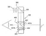
図1は、このような既知のオフサルミックディスプレイの平面図である。
レンズ300内には、プリズム401Aと、バッキングプリズム401Bと、四分波プレート404と、マンジャン鏡403とから構成された光学結像器インサート400が埋め込まれている。光学結像器インサート400は、薄膜の被覆物の形で実施することができる偏光分離処理部402を備えている。
【0005】
電子信号伝達情報は、図示していないケーブルによって小型スクリーンに運ばれる。小型スクリーン320は、バックライトプロジェクタによって照射され、情報に応じた画素画像を発生させることによってこの信号に応答する。
【0006】
小型スクリーン320から生じて点線で示した経路に続く光ビームは、中を偏光分離処理部402に到達するように通過するオフサルミックレンズ内でレンズ360及び鏡325を介して伝達される。スクリーンによって発せられる光ビームの偏光は、偏光分離処理部402上の光線の入射面にあるように向けられる。これは、P方向に向けられると言われる。光ビームは、その後バッキングプリズム401Bを通し、その後四分波プレート404を通してマンジャン鏡403まで伝播され、そこで四分波プレート404を通して反対方向に通過するように反射される。マンジャン鏡403の役割は、スクリーンの情報画像Iを作り出し、これをユーザに対して快適な視野距離にあるように位置決めすることである。普通、この視野距離は、画像が1メートル先にあるようにユーザに見えるように調節される。さらに、画像の見かけの寸法は、光学結像器インサート400の特徴に応じて対角線に沿って約12度であってもよい。
【0007】
四分波プレート404は、光ビームの分光に対して45度に向けられた軸を有する。したがって、光ビームの第1の通過の際、円形の偏光状態で出る。最後に、第2の通過の終わりには、光ビームは直線偏光状態にあるが、初期偏光に対して90度に向けられている。このように、マンジャン鏡403によって反射した光ビームが四分波プレート404を通して2回通過すると、偏光分離処理が行なわれ、そこで普通はSと書かれた入射平面に垂直な偏光方向を有する。したがって、マンジャン鏡403を介して小型スクリーン320の情報画像Iを見る着用者の眼に対して高い測光効率で反射される。
【0008】
このようなディスプレイは、以下の問題を呈する。
光学結像器インサート400は、光学結像器インサート400の前部領域に等しい面積の立方体を実質的に占めており、この領域内では周囲の視界が遮られる。立方体の外側では、眼鏡の着用者はオフサルミックレンズ300を通して周囲を見ることができる。
システムによって表示される情報画像Iは、外部環境から来る光の重なりによりコントラストの損失が起こることが分かった。この現象は、情報眼鏡が外で使用される場合に特に顕著である。
【0009】
コントラストは以下のように定義される:
C=(Ion−Ioff)/(Ion+Ioff)
式中、Ionは周囲の前に配置された情報画像を見る場合に眼が受ける強度であり、Ioffは情報画像なしで周囲を見る場合に眼が受ける画像である。
【0010】
さらに、レンズに含まれる偏光分離立方体である光学結像器インサート400は、外から見え、魅力のない外観効果が生じる。これは、全体の50%の非偏光周辺光しか通過させることができない偏光分離多層処理によるものである。
【発明の開示】
【発明が解決しようとする課題】
【0011】
本発明の目的は、適切なコントラストを画像内で保護することを可能にし、ほとんど見えなくするように立方体を隠すことによって、これらの問題を解決することを可能にするオフサルミックディスプレイを提案することである。
【課題を解決するための手段】
【0012】
本発明は、情報画像(I)を提供する小型スクリーン(320)を備え、着用者は光学結像器インサート(400)を介して前記小型スクリーン(320)からの前記情報画像(I)を見るオフサルミックディスプレイであって、第1偏光方向の偏光透過度を有して光ビームを通過させ、着用者の眼(1)に向けて、前記情報画像(I)が見られるようにする前記光学結像器インサート(400)を有し、周囲からの光を通すオフサルミックレンズ(300)を備え、第2偏光方向を有する偏光子(2A)と偏光方向を調節可能なエレメント(2B)から構成され前記オフサルミックレンズ(300)の周囲の光が入る前面の全体に配置される少なくとも1つの偏光器エレメント(2)を含み、前記光学結像器インサート(400)を介して前記情報画像(I)を見る場合に、偏光方向を調節可能な前記エレメント(2B)は 第1の偏光方向に垂直な偏光として前記光学結像器インサート(400)を通過する前記周囲からの光を遮り、前記光学結像器インサート(400)を介して前記情報画像(I)を見ない場合は、前記エレメント(2B)は、光の偏光方向を第1偏光方向に平行な偏光にして、前記偏光器エレメント(2)は前記光学結像器インサート(400)を隠す、ことを特徴とする。
【0013】
本発明のオフサルミックディスプレイによれば、適切なコントラストを画像内で保護することを可能にし、偏光分離立方体である光学結像器インサート400が不透明になり、したがって光学結像器インサート400は、外部の観察者にはあまり見えなくなる。
【発明を実施するための最良の形態】
【0014】
本発明の好ましい実施形態を図面を参照して詳細に説明する。
図2は、本発明の略図である。
図3は、特定の実施形態における、本発明によるオフサルミックディスプレイの断面図である。
図4は、別の特定の実施形態を構成する、本発明によるオフサルミックディスプレイを示す。
【0015】
図2は、光学結像器インサート400を含むオフサルミックレンズ300を示している。例として、光学結像器インサート400は、上記米国特許第5886822号に記載されたものと同じタイプであってもよい。
【0016】
本発明によるオフサルミックディスプレイは、偏光方向をPにする光学結像器インサート400を含むオフサルミックレンズ300を備え、光ビームを形成して、これらをユーザの眼1に向け、情報内容を見ることができるようにしている。オフサルミックディスプレイはまた、オフサルミックレンズ300の面の一方、好ましくはその前面に配置するための偏光器エレメント2を備えている。
【0017】
このような偏光分離器立方体である光学結像器インサート400は、ほぼ90%以上の高いP偏光透過度、及び低いS偏光透過度を示し、これはほぼ90%以上の高いS偏光反射、及び低いP偏光反射を示す。
【0018】
従って、光学結像器インサート400は、P偏光を有し、この実施形態で偏光器2は光学結像器インサート400と平行に偏光する。
【0019】
この構成では、偏光分離器立方体である光学結像器インサート400の偏光方向Pへの偏光器2の偏光方向の位置合わせは、透過度をレンズ全体の上でより均一にする効果を有する。外部の観察者への多層処理404の視認性はしたがって、かなり減少する。
【0020】
例として、偏光器なしのオフサルミックレンズ300が白色シート上に配置されると仮定する。レンズの残りの部分を通した周囲の透過度はそれにより、ほぼ100%であり、偏光分離器立方体である光学結像器インサート400を通した周囲の透過度は偏光されていない光ではほぼ50%である。偏光分離器立方体である光学結像器インサート400はその後、0.33のコントラストを備えると考えられ、したがって明らかに見える。
【0021】
次に、オフサルミックレンズ300の前面が、光学結像器インサート400と平行な偏光方向に向けられた偏光器エレメント2を有すると仮定する。レンズの残りを通した周囲の透過度はほぼ50%であり、偏光分離器立方体である光学結像器インサート400を通した周囲の透過度はほぼ45%である。偏光分離器立方体である光学結像器インサート400はその後、約0.05のコントラストを備えると考えられ、これはほとんど見えない物体を示している。
【0022】
偏光器エレメント2は、フック又はマグネット部によってフレームに固定される適切なクリップにより眼鏡のフレームに固定することができ、取り外し可能なプレートによって構成することができる。
【0023】
偏光器エレメント2は、永久に又は一時的にレンズに接着結合されるのに適切なフィルムによって構成することができる。
偏光器エレメント2は、レンズ上のフィルム上に被着される層によって構成することができる。例えば、このタイプの偏光器はフィルム、ブラシがけされた分子、又は当業者に知られている種類のワイヤ偏光子によって構成することができる。
【0024】
特定の実施形態では、偏光器エレメント2は調節可能な偏光を備えたエレメントによって構成される。このような状況で、大きさを調節可能である偏光回転を示すキラル分子に基づく活性フィルムによって構成することができる。
【0025】
普通、このタイプの調節可能な偏光エレメントでは、液晶層には従来の偏光子が取り付けられている。制御電圧を加えることによって、全体として偏光子の方向を変更することが可能である。偏光方向制御は、制御部を使用してユーザによって設定される。有利には、制御部はオフサルミックディスプレイ用の全体の制御を行なう単一のハウジング内に一体化される。
【0026】
この実施形態は、所望の効果を得るため、偏光子の方向を調節することを可能にする利点を示している。
【0027】
光学結像器インサート400と平行な偏光器システムの偏光方向を設定することによって、外側から見えるインサートは上述のとおり隠される。
【0028】
偏光器システムの偏光方向を光学結像器インサート400と垂直になるように調節することによって、周囲環境の画像の輝度が低くなる。
【0029】
大きさの順序に関し、様々な照明状態において、約120カンデラ毎平方メートル(cd/m2)の輝度を備えたオフサルミックレンズ300によって表示される情報画像Iのコントラストは、本発明による偏光器を使用しない場合に、以下の表に示すように算出される。
偏光分離器立方体である光学結像器インサート400に対して交差する方向の偏光器エレメント2では、偏光分離器立方体である光学結像器インサート400を通る透過度はかなり減少する。偏光器エレメント2の効果がより大きくなり、偏光分離処理部402の分離処理がより良くなると、コントラストの改良も良くなる。理想的には、完全な偏光器エレメント2及び偏光分離処理部402では、得られるコントラストは1である。
【0031】
周囲の輝度と比較した情報画像のコントラストを改良することが望ましい構成では、偏光器の方向は偏光分離器立方体である光学結像器インサート400のP分光に交差する。このような状況では、レンズの残りの部分を通る周囲環境の透過度は約50%であり、偏光分離器立方体である光学結像器インサート400を通る周囲環境の透過度は0に近い。
【0032】
偏光分離器立方体である光学結像器インサート400がほぼ90%の効率を示し、偏光器がほぼ99%の効率を示すと仮定すると、以下のコントラスト値が本発明により得られる。
前の表と比較すると、コントラストはかなり大きく改善されており、「雲量」タイプの屋外状況、及びおそらく「日光」の状況でも装置を使用できることが容易に分かる。
【0034】
偏光器エレメント2が調節可能な分光を提供するエレメントによって構成されない場合、オフサルミックディスプレイも、光学結像器インサート400と同じ偏光を示し、オフサルミックレンズ300の面の一方に配置する第2の偏光器エレメントを含むことが有利である。
【0035】
装置が単に日光を補正するレンズとして使用される場合、ユーザは光学結像器インサート400を隠すように働く第2の偏光器エレメント2を使用する。
装置が光学結像器インサート400により情報画像Iを見るためのレンズとして使用される場合、ユーザは必要に応じて、周囲の輝度がかなりある場合でも画像のコントラストを最適化する第2の偏光器エレメント2を使用する。
【0036】
【0036】
図3に示す特定の実施形態では、偏光器エレメント2は光の振動方向を変更するエレメント(2A、2B)から構成されオフサルミックレンズ(300)の面上に配置される。
【0037】
調節可能な偏光を有するエレメントの1つのタイプでは、液晶層2Bには従来の偏光子2Aが取り付けられている。制御電圧3により、
液晶層2Bを通過する光の偏光方向を変えることが可能である。偏光方向の制御は、制御部を使用してユーザによって設定される。
【0038】
静止状態では、液晶フィルム2Bには電圧は加えられない。したがって、液晶はレンズを通過する周囲からの光Lの偏光を変換しない。
【0039】
偏光器エレメント2がS方向を有する場合、偏光分離器立方体である光学結像器インサート400を通過する周囲からの光L1は偏光を持ち、偏光分離処理によって遮られるようになる。偏光分離器立方体である光学結像器インサート400が不透明になり、その後情報画像Iのコントラストは周囲背景の画像の上で改善される。
【0040】
逆に、偏光器エレメント2がP方向を有する場合、周囲からの光L1は、レンズの他の部分を通過する光Lとほぼ同等の透過度で偏光分離器立方体である光学結像器インサート400を右に通過する。光学結像器インサート400はしたがって、外部の観察者にはあまり見えなくなる。
【0041】
動的状態では、電圧Vが液晶フィルム2Bに加えられる。この電圧Vは、液晶が光の偏光を90度回転させるような技術により算出される。したがって、偏光子2AがP偏光を向いている場合、液晶層2Bからの出口では、偏光はSであり、偏光子2AがS偏光を向いている場合、液晶層からの出口ではPとなるだろう。これにより、静止状態で得られる挙動と反対の挙動が提供される。
【0042】
別の方法では、電圧Vを任意選択で連続的に、0ボルト(V)からUボルトの範囲にわたって変え、液晶によって偏光に加えられる回転を変調することが可能になる。これにより、ユーザによって選択されたような、光学結像器インサート400の小さな可視性と周囲に対するより優れたコントラストの間の妥協を得るように遷移挙動を得ることが可能になる。
【0043】
図4に示すように、偏光方向を局所的に変調することができるように、液晶フィルム2Bを画素化することが可能である。各画素は、既知の角度で偏光を旋回させるように働く電気信号で個別に処理される。これらの技術は、液晶ディスプレイ(LCD)スクリーンの分野で知られている。これにより、制御可能な方法で、偏光の透過度を空間で変調することが可能になる。これは、インサート偽装機能、又は改良コントラスト機能の何れかを保持しながら、ユーザによって選択することができる状態で高度の偏光を示す周囲(水面、太陽と反対側の青空、反射止めガラスなど)を見るのに有用である。
【0044】
例として、図4は周囲から来るガラスからの側部反射RVを示している。液晶フィルム2Bは、偏光Sを有する画素PI(S)及び偏光Pを有する画素PI(P)を有する。第1の画素PI(S)は、周囲環境に対してコントラストを良くするように働く。第2の画素PI(P)は、側部から来る反射RVを遮断するように働く。周囲環境からの残りの光は、矢印Lで示されている。
【図面の簡単な説明】
【0045】
【図1】既知のオフサルミックディスプレイの平面図である。
【図2】本発明の略図である。
【図3】本発明による特定の実施形態のオフサルミックディスプレイの断面図である。
【図4】本発明による他の特定の実施形態のオフサルミックディスプレイを示す。
【符号の説明】
【0046】
1 眼
2 偏光器エレメント
3 制御電圧
300 オフサルミックレンズ
320 小型スクリーン
325 鏡
360 レンズ
400 光学結像器インサート、偏光分離器立方体
401A プリズム
401B バッキングプリズム
402 偏光分離処理部
403 マンジャン鏡
404 四分波プレート
I 情報画像
PI(P) 偏光Sを有する画素
PI(S) 偏光Pを有する画素【Technical field】
[0001]
The present invention relates to an ophthalmic display comprising an ophthalmic lens and an optical imager that makes it possible to project image or multimedia type information.
[Background]
[0002]
The term “lens” relates more particularly to an optional correction lens suitable for mounting on a pair of spectacle frames. Such an ophthalmic lens can exhibit, for example, conventional vision correction, antireflection, antifouling, and scratch prevention functions.
[0003]
U.S. Pat. No. 5,886,822 discloses an ophthalmic lens showing a projection insert. Such projection inserts are constituted by an optical imager that shapes a light beam originating from an electronic and optical system that generates a light beam from a small screen, laser diode, or light emitting diode (LED) type electronic signal. The optical imager allows the light beam to be directed at the wearer's eye to see the information content.
[0004]
FIG. 1 is a plan view of such a known ophthalmic display.
Embedded in the
[0005]
Electronic signal transmission information is carried to a small screen by a cable (not shown). The
[0006]
The light beam generated from the
[0007]
The
[0008]
Such a display presents the following problems.
The optical imager insert 400 substantially occupies a cube with an area equal to the front region of theoptical imager insert400 , in which surrounding vision is obstructed. Outside the cube, eyeglass wearer can see the surrounding through
The information image I displayed by the system was found to lose contrast due to the overlap of light coming from the external environment. This phenomenon is particularly noticeable when the information glasses are used outside.
[0009]
Contrast is defined as follows:
C = (Ion−Ioff) / (Ion + Ioff)
In the formula, Ion is the intensity received by the eye when viewing the information image arranged in front of the surroundings, and Ioff is the image received by the eye when viewing the surroundings without the information image.
[0010]
Furthermore,the optical imager insert 400 ,which is a polarization splitting cube contained in the lens, is visible from the outside and produces an unattractive appearance effect. This is due to the polarization splitting multi-layer process that allows only 50% of the unpolarized ambient light to pass through.
DISCLOSURE OF THE INVENTION
[Problems to be solved by the invention]
[0011]
The object of the present invention proposes an ophthalmic display that makes it possible to solve these problems by allowing appropriate contrast to be protected in the image and hiding the cube so that it is almost invisible. That is.
[Means for Solving the Problems]
[0012]
The present invention comprises a small screen (320) that provides an information image (I), and the wearer views the information image (I) from the small screen (320) via an optical imager insert (400). An ophthalmic display, wherein the information image (I) is viewed toward a wearer's eye (1)by passing a light beam having a polarization transmittance in a first polarization direction.A polarizer (2A)having a second polarization direction and an element (2B) having an optical imager insert (400), an ophthalmic lens (300) through which light from the surroundings passes,and an adjustable polarization direction comprises at least one polarizer elementsambient light is arranged onthe entire front surface enters the configured theophthalmic lenses (300) (2) from, via the optical imager insert (400) When viewing the serial information image (I), the light from the surroundings through an adjustable the element the polarization direction (2B) said optical imaging device insert (400)as a polarization perpendicular to the first polarization direction And when the information image (I) is not viewed through the optical imager insert (400), the element (2B) changes the polarization direction ofthe light to a polarization parallel tothe first polarization direction . The polarizer element (2) conceals the optical imager insert (400).
[0013]
According to the ophthalmic display of the present invention, it is possible to protect the appropriate contrast in the image,and the optical imager insert 400,which is apolarization separation cube, becomes opaque, so the
BEST MODE FOR CARRYING OUT THE INVENTION
[0014]
Preferred embodiments of the present invention will be described in detailwith reference to the drawings.
FIG. 2 is a schematic diagram of the present invention.
FIG. 3 is a cross-sectional view of anophthalmic display according to the present invention in a specific embodiment.
FIG. 4 shows anophthalmic display according to the invention that constitutes another particular embodiment.
[0015]
FIG. 2 shows an
[0016]
Theophthalmic display according to the present inventionincludes an
[0017]
The
[0018]
Accordingly, the
[0019]
In this configuration, alignment of the polarization direction of the
[0020]
As an example, assume that an
[0021]
Next, assume that the front surface of the
[0022]
The
[0023]
The
[0024]
In a particular embodiment, the
[0025]
Usually, in this type of adjustable polarizing element, a conventional polarizer is attached to the liquid crystal layer. By applying a control voltage, it is possible to change the direction of the polarizer as a whole. The polarization direction control is set by the user using the control unit. Advantageously, the control is integrated in a single housing that provides overall control for the ophthalmic display.
[0026]
This embodiment shows the advantage of allowing the orientation of the polarizer to be adjusted in order to obtain the desired effect.
[0027]
By setting the polarization direction of the polarizer system parallel to the
[0028]
By adjusting the polarization direction of the polarizer system to be perpendicular to the
[0029]
Concerning the order of magnitude, the contrast of the information image I displayed by the
In the direction of the
[0031]
In a configuration where it is desirable to improve the contrast of the information image compared to the ambient brightness, the direction of thepolarizer intersects the P-spectrumof the
[0032]
Assumingthat the
Compared to the previous table, the contrast is significantly improved and it is easy to see that the device can be used in outdoor conditions of "cloudiness" type and possibly also in "sunlight" conditions.
[0034]
If the
[0035]
If the device is simply used as a lens to correct sunlight, the user uses a
If the device is used as a lens for viewing the information image I with the
[0036]
[0036]
In the specific embodiment shown in FIG. 3, the
[0037]
In one type of element having adjustable polarization, a
It is possibleto changethe polarization direction of the light passing through the
[0038]
In the stationary state, no voltage is applied to the
[0039]
When the
[0040]
Conversely, if the
[0041]
In the dynamic state, the voltage V is applied to the
[0042]
Another method allows the voltage V to be optionally and continuously varied over a range of 0 volts (V) to U volts to modulate the rotation applied to the polarization by the liquid crystal. This makes it possible to obtain transition behavior so as to obtain a compromise between the small visibility of the
[0043]
As shown in FIG. 4, the
[0044]
As an example, FIG. 4 shows the side reflection RV from the glass coming from the surroundings. The
[Brief description of the drawings]
[0045]
FIG. 1 is a plan view of a known ophthalmic display.
FIG. 2 is a schematic representation of the present invention.
FIG. 3 is a cross-sectional view of an embodiment ofan ophthalmic display according to the present invention.
FIG. 4 illustrates anophthalmic display of another specific embodiment according to the present invention.
[Explanation of symbols]
[0046]
1
Claims (3)
Translated fromJapanese第1偏光方向の偏光透過度を有して光ビームを通過させ、着用者の眼(1)に向けて、前記情報画像(I)が見られるようにする前記光学結像器インサート(400)を有し、周囲からの光を通すオフサルミックレンズ(300)を備え、
第2偏光方向を有する偏光子(2A)と偏光方向を調節可能なエレメント(2B)から構成され前記オフサルミックレンズ(300)の周囲の光が入る前面の全体に配置される少なくとも1つの偏光器エレメント(2)を含み、
前記光学結像器インサート(400)を介して前記情報画像(I)を見る場合に、偏光方向を調節可能な前記エレメント(2B)は 第1の偏光方向に垂直な偏光に変換して通過させ、前記光学結像器インサート(400)を通過する前記周囲からの光を遮り、
前記光学結像器インサート(400)を介して前記情報画像(I)を見ない場合は、前記エレメント(2B)は、光の偏光方向を第1偏光方向に平行な偏光に変換して通過させ、 前記偏光器エレメント(2)は前記光学結像器インサート(400)を隠す、
ことを特徴とするオフサルミックレンズ及び光学結像器インサートを備えたオフサルミックディスプレイ。An ophthalmic display comprising a small screen (320) providing an information image (I), wherein the wearer views the information image (I) from the small screen (320) via an optical imager insert (400) Because
The optical imager insert (400)having a polarization transmission in a first polarization direction and allowing the light beam to pass therethrough so that the information image (I) can be viewed towardsthe wearer's eye (1). An ophthalmic lens (300) that allows light from the surroundings to pass through,
The second at least one polarizationof ambient light are arranged onthe entire front surface enters thepolarization polarizer (2A) and configured the polarization direction from the adjustable element (2B) saidophthalmic lenshaving a direction (300) Including a vessel element (2),
When the information image (I) is viewed through the optical imager insert (400), the element (2B) whose polarization direction can be adjustedis converted into polarized light perpendicular to the first polarization direction and allowed to pass through. , block the light from the surroundings passing through the optical imager insert (400),
When the information image (I) is not viewed through the optical imager insert (400), the element (2B) converts the polarizationdirection of the light into polarized light parallel tothe first polarization direction and allows it to pass. The polarizer element (2) hides the optical imager insert (400);
An ophthalmic display comprising an ophthalmic lens and an optical imager insert.
Applications Claiming Priority (3)
| Application Number | Priority Date | Filing Date | Title |
|---|---|---|---|
| FR0452541 | 2004-11-05 | ||
| FR0452541AFR2877737B1 (en) | 2004-11-05 | 2004-11-05 | OPHTHALMIC DISPLAY HAVING AN OPHTHALMIC LENS AND AN OPTICAL IMAGER |
| PCT/FR2005/050829WO2006048564A1 (en) | 2004-11-05 | 2005-10-07 | Ophthalmic display comprising an ophthalmic lens and an optical image |
Publications (2)
| Publication Number | Publication Date |
|---|---|
| JP2008521023A JP2008521023A (en) | 2008-06-19 |
| JP4961594B2true JP4961594B2 (en) | 2012-06-27 |
Family
ID=34950042
Family Applications (1)
| Application Number | Title | Priority Date | Filing Date |
|---|---|---|---|
| JP2007539617AExpired - LifetimeJP4961594B2 (en) | 2004-11-05 | 2005-10-07 | Ophthalmic display with ophthalmic lens and optical imager insert |
Country Status (8)
| Country | Link |
|---|---|
| US (1) | US7791804B2 (en) |
| EP (1) | EP1807727B1 (en) |
| JP (1) | JP4961594B2 (en) |
| KR (1) | KR101129372B1 (en) |
| CN (1) | CN100456081C (en) |
| FR (1) | FR2877737B1 (en) |
| IL (1) | IL182567A (en) |
| WO (1) | WO2006048564A1 (en) |
Families Citing this family (7)
| Publication number | Priority date | Publication date | Assignee | Title |
|---|---|---|---|---|
| JP2009128649A (en)* | 2007-11-26 | 2009-06-11 | Nikon Corp | Combiner optical system and wearable display device |
| FR2926373B1 (en)* | 2008-01-11 | 2010-07-30 | Essilor Int | TRANSPARENT COMPONENT WITH SWITCHABLE REFLECTING ELEMENTS, AND DEVICES COMPRISING SUCH A COMPONENT |
| US9658454B2 (en) | 2013-09-06 | 2017-05-23 | Omnivision Technologies, Inc. | Eyewear display system providing vision enhancement |
| JP6640082B2 (en)* | 2013-11-19 | 2020-02-05 | スリーエム イノベイティブ プロパティズ カンパニー | Transparent head-mounted display with liquid crystal module for adjusting the brightness ratio of combined images |
| KR102069024B1 (en) | 2015-09-03 | 2020-01-22 | 쓰리엠 이노베이티브 프로퍼티즈 컴파니 | Optical system |
| CN105866953A (en)* | 2016-06-07 | 2016-08-17 | 北京行云时空科技有限公司 | Permeation rate control method and device based on smart glasses as well as smart glasses |
| CN110346936A (en)* | 2019-07-11 | 2019-10-18 | Oppo广东移动通信有限公司 | A kind of virtual real mode it is compatible with augmented reality mode wear display equipment |
Family Cites Families (10)
| Publication number | Priority date | Publication date | Assignee | Title |
|---|---|---|---|---|
| JP3260867B2 (en)* | 1992-12-10 | 2002-02-25 | オリンパス光学工業株式会社 | Head-mounted display |
| US5519459A (en)* | 1995-01-20 | 1996-05-21 | Moglianesi; Carlos | Dismountable variable intensity polarized lenses |
| US5598231A (en)* | 1995-12-04 | 1997-01-28 | Artificial Parallax Electronics Corp. | Glasses capable of producing a three-D visual effect |
| US6204974B1 (en)* | 1996-10-08 | 2001-03-20 | The Microoptical Corporation | Compact image display system for eyeglasses or other head-borne frames |
| US5886822A (en)* | 1996-10-08 | 1999-03-23 | The Microoptical Corporation | Image combining system for eyeglasses and face masks |
| CA2307877C (en)* | 1997-10-30 | 2005-08-30 | The Microoptical Corporation | Eyeglass interface system |
| US6747611B1 (en)* | 2000-07-27 | 2004-06-08 | International Business Machines Corporation | Compact optical system and packaging for head mounted display |
| JP2002148559A (en)* | 2000-11-15 | 2002-05-22 | Mixed Reality Systems Laboratory Inc | Image observing device and image observing system using the device |
| FR2828743B1 (en)* | 2001-08-14 | 2004-02-27 | Essilor Int | METHOD FOR MOLDING A LENS HAVING AN INSERT |
| FR2847988B1 (en)* | 2002-12-03 | 2005-02-25 | Essilor Int | POLARIZATION SEPARATOR, PROCESS FOR MANUFACTURING THE SAME, AND OPHTHALMIC LENS HAVING PROJECTION INSERTS CONTAINING THE SAME |
- 2004
- 2004-11-05FRFR0452541Apatent/FR2877737B1/ennot_activeExpired - Fee Related
- 2005
- 2005-10-07JPJP2007539617Apatent/JP4961594B2/ennot_activeExpired - Lifetime
- 2005-10-07USUS11/787,067patent/US7791804B2/ennot_activeExpired - Lifetime
- 2005-10-07EPEP05810805.1Apatent/EP1807727B1/ennot_activeExpired - Lifetime
- 2005-10-07WOPCT/FR2005/050829patent/WO2006048564A1/enactiveApplication Filing
- 2005-10-07KRKR1020077012233Apatent/KR101129372B1/ennot_activeExpired - Lifetime
- 2005-10-07CNCNB2005800363930Apatent/CN100456081C/ennot_activeExpired - Lifetime
- 2007
- 2007-04-16ILIL182567Apatent/IL182567A/enactiveIP Right Grant
Also Published As
| Publication number | Publication date |
|---|---|
| EP1807727A1 (en) | 2007-07-18 |
| JP2008521023A (en) | 2008-06-19 |
| WO2006048564A1 (en) | 2006-05-11 |
| CN100456081C (en) | 2009-01-28 |
| IL182567A0 (en) | 2007-07-24 |
| KR101129372B1 (en) | 2012-03-26 |
| FR2877737B1 (en) | 2007-01-19 |
| US20090009713A1 (en) | 2009-01-08 |
| EP1807727B1 (en) | 2015-02-18 |
| KR20070085584A (en) | 2007-08-27 |
| IL182567A (en) | 2011-04-28 |
| FR2877737A1 (en) | 2006-05-12 |
| CN101048693A (en) | 2007-10-03 |
| US7791804B2 (en) | 2010-09-07 |
Similar Documents
| Publication | Publication Date | Title |
|---|---|---|
| US11644675B2 (en) | Ghost image mitigation in see-through displays with pixel arrays | |
| US9429757B1 (en) | System for providing projected information combined with outside scenery | |
| CN114730068B (en) | Ambient light management system and method for wearable devices | |
| US9087471B2 (en) | Adaptive brightness control of head mounted display | |
| US8503085B2 (en) | Head-mounted display | |
| US10036890B2 (en) | Head-up display device | |
| JP7476244B2 (en) | Geometry for reducing artifacts in see-through pixel arrays | |
| JP4835327B2 (en) | Image display device and head-mounted image display device | |
| JP2017504819A (en) | Perspective head-mounted display with liquid crystal module for adjusting the luminance ratio of combined images | |
| US20190004350A1 (en) | Display apparatus and method of displaying using polarizers and optical combiners | |
| KR20200095985A (en) | A head mounted display apparatus using discoloration lens and illumination sensor | |
| US20090009713A1 (en) | Ophthalmic display comprising an ophthalmic lens and an optical imager | |
| JP2008046562A (en) | Head-mounted display | |
| JPH1010522A (en) | Liquid crystal display | |
| US7193767B1 (en) | Method for enhancing visibility | |
| CN111258073B (en) | Reflective Display Glasses | |
| US6947013B2 (en) | Display device combining ambient light with magnified virtual images generated in the eye path of the observer | |
| JP3531348B2 (en) | Optical components | |
| US20160094820A1 (en) | System for balancing the brightness of 2D and 3D cinema presentation | |
| CN111123519B (en) | Near-to-eye display system and device with manually adjustable transparency | |
| US20250060588A1 (en) | Display system for providing high contrast ratio and reducing rainbow effect | |
| US20240302697A1 (en) | Achromatic wave plates based on compound twisted and untwisted nematic liquid crystal polymer | |
| KR20200096000A (en) | A head mounted display apparatus using discoloration lens | |
| WO2025042793A1 (en) | Display system for providing high contrast ratio and reducing rainbow effect |
Legal Events
| Date | Code | Title | Description |
|---|---|---|---|
| A621 | Written request for application examination | Free format text:JAPANESE INTERMEDIATE CODE: A621 Effective date:20080702 | |
| A131 | Notification of reasons for refusal | Free format text:JAPANESE INTERMEDIATE CODE: A131 Effective date:20100831 | |
| A977 | Report on retrieval | Free format text:JAPANESE INTERMEDIATE CODE: A971007 Effective date:20100831 | |
| A601 | Written request for extension of time | Free format text:JAPANESE INTERMEDIATE CODE: A601 Effective date:20101130 | |
| A602 | Written permission of extension of time | Free format text:JAPANESE INTERMEDIATE CODE: A602 Effective date:20101207 | |
| A521 | Request for written amendment filed | Free format text:JAPANESE INTERMEDIATE CODE: A523 Effective date:20110104 | |
| A131 | Notification of reasons for refusal | Free format text:JAPANESE INTERMEDIATE CODE: A131 Effective date:20110426 | |
| A601 | Written request for extension of time | Free format text:JAPANESE INTERMEDIATE CODE: A601 Effective date:20110711 | |
| A601 | Written request for extension of time | Free format text:JAPANESE INTERMEDIATE CODE: A601 Effective date:20110823 | |
| A521 | Request for written amendment filed | Free format text:JAPANESE INTERMEDIATE CODE: A523 Effective date:20110819 | |
| A602 | Written permission of extension of time | Free format text:JAPANESE INTERMEDIATE CODE: A602 Effective date:20110801 | |
| A521 | Request for written amendment filed | Free format text:JAPANESE INTERMEDIATE CODE: A523 Effective date:20110926 | |
| A521 | Request for written amendment filed | Free format text:JAPANESE INTERMEDIATE CODE: A523 Effective date:20110926 | |
| A602 | Written permission of extension of time | Free format text:JAPANESE INTERMEDIATE CODE: A602 Effective date:20110913 | |
| A131 | Notification of reasons for refusal | Free format text:JAPANESE INTERMEDIATE CODE: A131 Effective date:20111101 | |
| A521 | Request for written amendment filed | Free format text:JAPANESE INTERMEDIATE CODE: A523 Effective date:20120201 | |
| TRDD | Decision of grant or rejection written | ||
| A01 | Written decision to grant a patent or to grant a registration (utility model) | Free format text:JAPANESE INTERMEDIATE CODE: A01 Effective date:20120214 | |
| A01 | Written decision to grant a patent or to grant a registration (utility model) | Free format text:JAPANESE INTERMEDIATE CODE: A01 | |
| A61 | First payment of annual fees (during grant procedure) | Free format text:JAPANESE INTERMEDIATE CODE: A61 Effective date:20120306 | |
| R150 | Certificate of patent or registration of utility model | Ref document number:4961594 Country of ref document:JP Free format text:JAPANESE INTERMEDIATE CODE: R150 Free format text:JAPANESE INTERMEDIATE CODE: R150 | |
| FPAY | Renewal fee payment (event date is renewal date of database) | Free format text:PAYMENT UNTIL: 20150406 Year of fee payment:3 | |
| R250 | Receipt of annual fees | Free format text:JAPANESE INTERMEDIATE CODE: R250 | |
| R250 | Receipt of annual fees | Free format text:JAPANESE INTERMEDIATE CODE: R250 | |
| R250 | Receipt of annual fees | Free format text:JAPANESE INTERMEDIATE CODE: R250 | |
| R250 | Receipt of annual fees | Free format text:JAPANESE INTERMEDIATE CODE: R250 | |
| S111 | Request for change of ownership or part of ownership | Free format text:JAPANESE INTERMEDIATE CODE: R313113 | |
| R350 | Written notification of registration of transfer | Free format text:JAPANESE INTERMEDIATE CODE: R350 | |
| R250 | Receipt of annual fees | Free format text:JAPANESE INTERMEDIATE CODE: R250 | |
| R250 | Receipt of annual fees | Free format text:JAPANESE INTERMEDIATE CODE: R250 | |
| R250 | Receipt of annual fees | Free format text:JAPANESE INTERMEDIATE CODE: R250 | |
| R250 | Receipt of annual fees | Free format text:JAPANESE INTERMEDIATE CODE: R250 | |
| R250 | Receipt of annual fees | Free format text:JAPANESE INTERMEDIATE CODE: R250 | |
| R250 | Receipt of annual fees | Free format text:JAPANESE INTERMEDIATE CODE: R250 | |
| R250 | Receipt of annual fees | Free format text:JAPANESE INTERMEDIATE CODE: R250 |