JP4958896B2 - Control method and apparatus for energy delivery - Google Patents
Control method and apparatus for energy deliveryDownload PDFInfo
- Publication number
- JP4958896B2 JP4958896B2JP2008507962AJP2008507962AJP4958896B2JP 4958896 B2JP4958896 B2JP 4958896B2JP 2008507962 AJP2008507962 AJP 2008507962AJP 2008507962 AJP2008507962 AJP 2008507962AJP 4958896 B2JP4958896 B2JP 4958896B2
- Authority
- JP
- Japan
- Prior art keywords
- energy
- user interface
- treatment
- interface surface
- impedance
- Prior art date
- Legal status (The legal status is an assumption and is not a legal conclusion. Google has not performed a legal analysis and makes no representation as to the accuracy of the status listed.)
- Expired - Fee Related
Links
- 238000012384transportation and deliveryMethods0.000titleclaimsdescription64
- 238000000034methodMethods0.000titledescription44
- 238000011282treatmentMethods0.000claimsdescription133
- 230000000007visual effectEffects0.000claimsdescription64
- 238000012545processingMethods0.000claimsdescription41
- 230000004913activationEffects0.000claimsdescription29
- 230000001225therapeutic effectEffects0.000claimsdescription19
- 210000004072lungAnatomy0.000claimsdescription15
- 238000004891communicationMethods0.000claimsdescription9
- 238000001514detection methodMethods0.000claimsdescription4
- 210000001519tissueAnatomy0.000description53
- 210000000056organAnatomy0.000description43
- 238000009877renderingMethods0.000description15
- 208000006673asthmaDiseases0.000description13
- 238000010586diagramMethods0.000description13
- 210000002460smooth muscleAnatomy0.000description9
- 230000001276controlling effectEffects0.000description8
- 230000000994depressogenic effectEffects0.000description8
- 238000002560therapeutic procedureMethods0.000description8
- 230000009471actionEffects0.000description7
- 238000002591computed tomographyMethods0.000description7
- 230000033001locomotionEffects0.000description7
- 230000008859changeEffects0.000description6
- 238000007726management methodMethods0.000description6
- 230000008569processEffects0.000description6
- 239000000523sampleSubstances0.000description5
- 238000012360testing methodMethods0.000description5
- 238000004458analytical methodMethods0.000description4
- 238000012986modificationMethods0.000description4
- 230000004048modificationEffects0.000description4
- 210000005091airway smooth muscleAnatomy0.000description3
- 210000003484anatomyAnatomy0.000description3
- 230000008901benefitEffects0.000description3
- 238000003745diagnosisMethods0.000description3
- 230000000694effectsEffects0.000description3
- 239000002085irritantSubstances0.000description3
- 231100000021irritantToxicity0.000description3
- 238000002595magnetic resonance imagingMethods0.000description3
- 238000013507mappingMethods0.000description3
- 238000005259measurementMethods0.000description3
- 230000000144pharmacologic effectEffects0.000description3
- 238000002600positron emission tomographyMethods0.000description3
- 230000002685pulmonary effectEffects0.000description3
- 208000000059DyspneaDiseases0.000description2
- 206010013975DyspnoeasDiseases0.000description2
- 229940124599anti-inflammatory drugDrugs0.000description2
- 210000000845cartilageAnatomy0.000description2
- 230000008602contractionEffects0.000description2
- 230000000881depressing effectEffects0.000description2
- 238000010336energy treatmentMethods0.000description2
- 238000003384imaging methodMethods0.000description2
- 238000002847impedance measurementMethods0.000description2
- 230000000977initiatory effectEffects0.000description2
- 239000000463materialSubstances0.000description2
- 230000003287optical effectEffects0.000description2
- 238000002360preparation methodMethods0.000description2
- 230000002441reversible effectEffects0.000description2
- 238000003860storageMethods0.000description2
- 238000004448titrationMethods0.000description2
- 238000012285ultrasound imagingMethods0.000description2
- 210000005166vasculatureAnatomy0.000description2
- 208000000884Airway ObstructionDiseases0.000description1
- 206010006482BronchospasmDiseases0.000description1
- 206010008479Chest PainDiseases0.000description1
- 208000017667Chronic DiseaseDiseases0.000description1
- 206010011224CoughDiseases0.000description1
- 206010020751HypersensitivityDiseases0.000description1
- 206010061218InflammationDiseases0.000description1
- 206010036790Productive coughDiseases0.000description1
- 208000037656Respiratory SoundsDiseases0.000description1
- 206010039897SedationDiseases0.000description1
- 206010042674SwellingDiseases0.000description1
- 206010047924WheezingDiseases0.000description1
- 230000001154acute effectEffects0.000description1
- 230000009798acute exacerbationEffects0.000description1
- 239000000853adhesiveSubstances0.000description1
- 230000001070adhesive effectEffects0.000description1
- 208000037883airway inflammationDiseases0.000description1
- 230000004397blinkingEffects0.000description1
- 210000004204blood vesselAnatomy0.000description1
- 238000009529body temperature measurementMethods0.000description1
- 210000004556brainAnatomy0.000description1
- 210000000621bronchiAnatomy0.000description1
- 230000007885bronchoconstrictionEffects0.000description1
- 230000000295complement effectEffects0.000description1
- 239000012141concentrateSubstances0.000description1
- 239000004020conductorSubstances0.000description1
- 238000010276constructionMethods0.000description1
- 230000002596correlated effectEffects0.000description1
- 239000003246corticosteroidSubstances0.000description1
- 230000001351cycling effectEffects0.000description1
- 201000010099diseaseDiseases0.000description1
- 208000037265diseases, disorders, signs and symptomsDiseases0.000description1
- 230000009977dual effectEffects0.000description1
- 230000003511endothelial effectEffects0.000description1
- 210000000981epitheliumAnatomy0.000description1
- 210000003238esophagusAnatomy0.000description1
- 238000011156evaluationMethods0.000description1
- 239000012530fluidSubstances0.000description1
- 210000001035gastrointestinal tractAnatomy0.000description1
- 210000004907glandAnatomy0.000description1
- 230000035876healingEffects0.000description1
- 210000002216heartAnatomy0.000description1
- 230000002779inactivationEffects0.000description1
- 230000004054inflammatory processEffects0.000description1
- 238000009434installationMethods0.000description1
- 210000003734kidneyAnatomy0.000description1
- 210000004185liverAnatomy0.000description1
- 229940125386long-acting bronchodilatorDrugs0.000description1
- 230000007774longtermEffects0.000description1
- 229910044991metal oxideInorganic materials0.000description1
- 150000004706metal oxidesChemical class0.000description1
- 230000003843mucus productionEffects0.000description1
- 239000000615nonconductorSubstances0.000description1
- 230000000414obstructive effectEffects0.000description1
- 238000011369optimal treatmentMethods0.000description1
- 230000002085persistent effectEffects0.000description1
- 238000013439planningMethods0.000description1
- 239000000955prescription drugSubstances0.000description1
- 230000005855radiationEffects0.000description1
- 230000000306recurrent effectEffects0.000description1
- 208000023504respiratory system diseaseDiseases0.000description1
- 230000004044responseEffects0.000description1
- 230000036280sedationEffects0.000description1
- 239000004065semiconductorSubstances0.000description1
- 229940125387short-acting bronchodilatorDrugs0.000description1
- 208000013220shortness of breathDiseases0.000description1
- 230000011664signalingEffects0.000description1
- 230000016160smooth muscle contractionEffects0.000description1
- 208000024794sputumDiseases0.000description1
- 210000003802sputumAnatomy0.000description1
- 238000011272standard treatmentMethods0.000description1
- 150000003431steroidsChemical class0.000description1
- 230000008961swellingEffects0.000description1
- 208000024891symptomDiseases0.000description1
- 230000026676system processEffects0.000description1
- 230000009885systemic effectEffects0.000description1
- 238000012546transferMethods0.000description1
- 230000007704transitionEffects0.000description1
- 230000001960triggered effectEffects0.000description1
- 238000013024troubleshootingMethods0.000description1
- 210000003932urinary bladderAnatomy0.000description1
Images


Classifications
- A—HUMAN NECESSITIES
- A61—MEDICAL OR VETERINARY SCIENCE; HYGIENE
- A61B—DIAGNOSIS; SURGERY; IDENTIFICATION
- A61B18/00—Surgical instruments, devices or methods for transferring non-mechanical forms of energy to or from the body
- A61B18/04—Surgical instruments, devices or methods for transferring non-mechanical forms of energy to or from the body by heating
- A61B18/12—Surgical instruments, devices or methods for transferring non-mechanical forms of energy to or from the body by heating by passing a current through the tissue to be heated, e.g. high-frequency current
- A61B18/14—Probes or electrodes therefor
- A61B18/1492—Probes or electrodes therefor having a flexible, catheter-like structure, e.g. for heart ablation
- A—HUMAN NECESSITIES
- A61—MEDICAL OR VETERINARY SCIENCE; HYGIENE
- A61B—DIAGNOSIS; SURGERY; IDENTIFICATION
- A61B18/00—Surgical instruments, devices or methods for transferring non-mechanical forms of energy to or from the body
- A61B18/04—Surgical instruments, devices or methods for transferring non-mechanical forms of energy to or from the body by heating
- A61B18/12—Surgical instruments, devices or methods for transferring non-mechanical forms of energy to or from the body by heating by passing a current through the tissue to be heated, e.g. high-frequency current
- A61B18/1206—Generators therefor
- A61B18/1233—Generators therefor with circuits for assuring patient safety
- A—HUMAN NECESSITIES
- A61—MEDICAL OR VETERINARY SCIENCE; HYGIENE
- A61B—DIAGNOSIS; SURGERY; IDENTIFICATION
- A61B34/00—Computer-aided surgery; Manipulators or robots specially adapted for use in surgery
- A61B34/20—Surgical navigation systems; Devices for tracking or guiding surgical instruments, e.g. for frameless stereotaxis
- A—HUMAN NECESSITIES
- A61—MEDICAL OR VETERINARY SCIENCE; HYGIENE
- A61N—ELECTROTHERAPY; MAGNETOTHERAPY; RADIATION THERAPY; ULTRASOUND THERAPY
- A61N1/00—Electrotherapy; Circuits therefor
- A61N1/02—Details
- A61N1/04—Electrodes
- A61N1/06—Electrodes for high-frequency therapy
- A—HUMAN NECESSITIES
- A61—MEDICAL OR VETERINARY SCIENCE; HYGIENE
- A61N—ELECTROTHERAPY; MAGNETOTHERAPY; RADIATION THERAPY; ULTRASOUND THERAPY
- A61N1/00—Electrotherapy; Circuits therefor
- A61N1/18—Applying electric currents by contact electrodes
- A61N1/32—Applying electric currents by contact electrodes alternating or intermittent currents
- A61N1/36—Applying electric currents by contact electrodes alternating or intermittent currents for stimulation
- A61N1/3601—Applying electric currents by contact electrodes alternating or intermittent currents for stimulation of respiratory organs
- A—HUMAN NECESSITIES
- A61—MEDICAL OR VETERINARY SCIENCE; HYGIENE
- A61N—ELECTROTHERAPY; MAGNETOTHERAPY; RADIATION THERAPY; ULTRASOUND THERAPY
- A61N1/00—Electrotherapy; Circuits therefor
- A61N1/40—Applying electric fields by inductive or capacitive coupling ; Applying radio-frequency signals
- A61N1/403—Applying electric fields by inductive or capacitive coupling ; Applying radio-frequency signals for thermotherapy, e.g. hyperthermia
- A—HUMAN NECESSITIES
- A61—MEDICAL OR VETERINARY SCIENCE; HYGIENE
- A61B—DIAGNOSIS; SURGERY; IDENTIFICATION
- A61B17/00—Surgical instruments, devices or methods
- A61B2017/00017—Electrical control of surgical instruments
- A61B2017/00115—Electrical control of surgical instruments with audible or visual output
- A61B2017/00119—Electrical control of surgical instruments with audible or visual output alarm; indicating an abnormal situation
- A—HUMAN NECESSITIES
- A61—MEDICAL OR VETERINARY SCIENCE; HYGIENE
- A61B—DIAGNOSIS; SURGERY; IDENTIFICATION
- A61B18/00—Surgical instruments, devices or methods for transferring non-mechanical forms of energy to or from the body
- A61B2018/00053—Mechanical features of the instrument of device
- A61B2018/00214—Expandable means emitting energy, e.g. by elements carried thereon
- A61B2018/00267—Expandable means emitting energy, e.g. by elements carried thereon having a basket shaped structure
- A—HUMAN NECESSITIES
- A61—MEDICAL OR VETERINARY SCIENCE; HYGIENE
- A61B—DIAGNOSIS; SURGERY; IDENTIFICATION
- A61B18/00—Surgical instruments, devices or methods for transferring non-mechanical forms of energy to or from the body
- A61B2018/00315—Surgical instruments, devices or methods for transferring non-mechanical forms of energy to or from the body for treatment of particular body parts
- A61B2018/00541—Lung or bronchi
- A—HUMAN NECESSITIES
- A61—MEDICAL OR VETERINARY SCIENCE; HYGIENE
- A61B—DIAGNOSIS; SURGERY; IDENTIFICATION
- A61B18/00—Surgical instruments, devices or methods for transferring non-mechanical forms of energy to or from the body
- A61B2018/00636—Sensing and controlling the application of energy
- A61B2018/00666—Sensing and controlling the application of energy using a threshold value
- A61B2018/00678—Sensing and controlling the application of energy using a threshold value upper
- A—HUMAN NECESSITIES
- A61—MEDICAL OR VETERINARY SCIENCE; HYGIENE
- A61B—DIAGNOSIS; SURGERY; IDENTIFICATION
- A61B18/00—Surgical instruments, devices or methods for transferring non-mechanical forms of energy to or from the body
- A61B2018/00636—Sensing and controlling the application of energy
- A61B2018/00696—Controlled or regulated parameters
- A61B2018/00702—Power or energy
- A—HUMAN NECESSITIES
- A61—MEDICAL OR VETERINARY SCIENCE; HYGIENE
- A61B—DIAGNOSIS; SURGERY; IDENTIFICATION
- A61B18/00—Surgical instruments, devices or methods for transferring non-mechanical forms of energy to or from the body
- A61B2018/00636—Sensing and controlling the application of energy
- A61B2018/00773—Sensed parameters
- A61B2018/00791—Temperature
- A—HUMAN NECESSITIES
- A61—MEDICAL OR VETERINARY SCIENCE; HYGIENE
- A61B—DIAGNOSIS; SURGERY; IDENTIFICATION
- A61B18/00—Surgical instruments, devices or methods for transferring non-mechanical forms of energy to or from the body
- A61B2018/00636—Sensing and controlling the application of energy
- A61B2018/00898—Alarms or notifications created in response to an abnormal condition
- A—HUMAN NECESSITIES
- A61—MEDICAL OR VETERINARY SCIENCE; HYGIENE
- A61B—DIAGNOSIS; SURGERY; IDENTIFICATION
- A61B18/00—Surgical instruments, devices or methods for transferring non-mechanical forms of energy to or from the body
- A61B18/04—Surgical instruments, devices or methods for transferring non-mechanical forms of energy to or from the body by heating
- A61B18/12—Surgical instruments, devices or methods for transferring non-mechanical forms of energy to or from the body by heating by passing a current through the tissue to be heated, e.g. high-frequency current
- A61B18/14—Probes or electrodes therefor
- A61B2018/1475—Electrodes retractable in or deployable from a housing
- A—HUMAN NECESSITIES
- A61—MEDICAL OR VETERINARY SCIENCE; HYGIENE
- A61B—DIAGNOSIS; SURGERY; IDENTIFICATION
- A61B34/00—Computer-aided surgery; Manipulators or robots specially adapted for use in surgery
- A61B34/20—Surgical navigation systems; Devices for tracking or guiding surgical instruments, e.g. for frameless stereotaxis
- A61B2034/2046—Tracking techniques
- A61B2034/2051—Electromagnetic tracking systems
- A—HUMAN NECESSITIES
- A61—MEDICAL OR VETERINARY SCIENCE; HYGIENE
- A61B—DIAGNOSIS; SURGERY; IDENTIFICATION
- A61B90/00—Instruments, implements or accessories specially adapted for surgery or diagnosis and not covered by any of the groups A61B1/00 - A61B50/00, e.g. for luxation treatment or for protecting wound edges
- A61B90/30—Devices for illuminating a surgical field, the devices having an interrelation with other surgical devices or with a surgical procedure
- A61B2090/309—Devices for illuminating a surgical field, the devices having an interrelation with other surgical devices or with a surgical procedure using white LEDs
- A—HUMAN NECESSITIES
- A61—MEDICAL OR VETERINARY SCIENCE; HYGIENE
- A61B—DIAGNOSIS; SURGERY; IDENTIFICATION
- A61B90/00—Instruments, implements or accessories specially adapted for surgery or diagnosis and not covered by any of the groups A61B1/00 - A61B50/00, e.g. for luxation treatment or for protecting wound edges
- A61B90/36—Image-producing devices or illumination devices not otherwise provided for
- A61B2090/364—Correlation of different images or relation of image positions in respect to the body
- A61B2090/365—Correlation of different images or relation of image positions in respect to the body augmented reality, i.e. correlating a live optical image with another image
- A—HUMAN NECESSITIES
- A61—MEDICAL OR VETERINARY SCIENCE; HYGIENE
- A61B—DIAGNOSIS; SURGERY; IDENTIFICATION
- A61B34/00—Computer-aided surgery; Manipulators or robots specially adapted for use in surgery
- A61B34/25—User interfaces for surgical systems
- A—HUMAN NECESSITIES
- A61—MEDICAL OR VETERINARY SCIENCE; HYGIENE
- A61B—DIAGNOSIS; SURGERY; IDENTIFICATION
- A61B90/00—Instruments, implements or accessories specially adapted for surgery or diagnosis and not covered by any of the groups A61B1/00 - A61B50/00, e.g. for luxation treatment or for protecting wound edges
- A61B90/36—Image-producing devices or illumination devices not otherwise provided for
- A61B90/361—Image-producing devices, e.g. surgical cameras
Landscapes
- Health & Medical Sciences (AREA)
- Life Sciences & Earth Sciences (AREA)
- Engineering & Computer Science (AREA)
- Biomedical Technology (AREA)
- Nuclear Medicine, Radiotherapy & Molecular Imaging (AREA)
- Animal Behavior & Ethology (AREA)
- General Health & Medical Sciences (AREA)
- Public Health (AREA)
- Veterinary Medicine (AREA)
- Surgery (AREA)
- Radiology & Medical Imaging (AREA)
- Medical Informatics (AREA)
- Molecular Biology (AREA)
- Heart & Thoracic Surgery (AREA)
- Physics & Mathematics (AREA)
- Otolaryngology (AREA)
- Plasma & Fusion (AREA)
- Pulmonology (AREA)
- Physiology (AREA)
- Cardiology (AREA)
- Robotics (AREA)
- Surgical Instruments (AREA)
- Biophysics (AREA)
- Pathology (AREA)
- Optics & Photonics (AREA)
- High Energy & Nuclear Physics (AREA)
- Theoretical Computer Science (AREA)
- External Artificial Organs (AREA)
- Control Of Temperature (AREA)
Description
Translated fromJapanese (関連出願の引用)
本願は、米国仮特許出願第60/674,106号および同第60/673,876号(ともに2005年4月21日出願)の35U.S.C.§119(e)での利益を主張し、各出願の内容は本明細書において参照により援用される。(Citation of related application)
No. 60 / 674,106 and 60 / 673,876 (both filed April 21, 2005). S. C. Claiming the benefit in §119 (e), the contents of each application are hereby incorporated by reference.
様々な閉塞性気道疾患は、いくつかの可逆性成分を有する。実例にはCOPDおよびぜんそくが含まれる。ぜんそくは、気管支収縮の過度の粘液産生ならびに気道の炎症および腫れが起こり、広範囲に及ぶが変化しやすい気道閉塞を引き起こすことによってぜんそく患者が呼吸するのを困難にさせる病気である。ぜんそくは、主として持続性気道炎症によって特徴付けられる慢性疾患である。ぜんそくは、過敏反応性気道平滑筋の収縮により狭くなる付加的気道の急性発症によってさらに特徴付けられる。 Various obstructive airway diseases have several reversible components. Examples include COPD and asthma. Asthma is a disease that makes it difficult for asthmatics to breathe by producing excessive mucus production of bronchoconstriction and inflammation and swelling of the airways, causing extensive but variable airway obstruction. Asthma is a chronic disease characterized primarily by persistent airway inflammation. Asthma is further characterized by an acute onset of additional airways narrowed by hypersensitive reactive airway smooth muscle contraction.
影響を受けやすい個人では、ぜんそく症状には、息切れ(呼吸困難)、喘鳴、胸苦しさおよび咳の再発性の発症が含まれる。目下、ぜんそくは、刺激物回避および薬理学の組み合わせによって対処されている。刺激物回避は、全身の同定およびそれぞれのタイプの刺激物との接触を最小化することにより達成される。しかしながら、全ての可能性のある刺激物を回避することは非実用的であり、常に有用とは限らない場合がある。 In susceptible individuals, asthma symptoms include shortness of breath (dyspnea), wheezing, chest pain, and recurrent episodes of cough. Currently, asthma is addressed by a combination of irritant avoidance and pharmacology. Stimulus avoidance is achieved by minimizing systemic identification and contact with each type of stimulus. However, avoiding all possible irritants is impractical and may not always be useful.
ぜんそくの薬理学的管理には、抗炎症薬および長時間作用型気管支拡張薬を使用する長期管理が含まれる。急性増悪期の短期間薬理学的管理は、短時間作用型気管支拡張薬を使用して実現する場合がある。これらの方法もどちらも、処方薬を繰り返し習慣的に使用することが要求される。コルチコステロイド抗炎症薬の高用量は、注意深く管理する必要がある重篤な副作用を有する。さらに、何人かの患者は、ステロイド治療に耐性を示す。薬理学的管理の患者の薬剤服用順守に関与する問題、およびぜんそくの誘因となる刺激物を回避することの困難性は、従来のぜんそく管理を成功させるのによくある障害となる。従って、管理システム、および習慣的な患者の薬剤服用順守を要求しない方法を提供することは望ましいということになる。 Pharmacological management of asthma includes long-term management using anti-inflammatory drugs and long-acting bronchodilators. Short-term pharmacological management of acute exacerbation may be achieved using short-acting bronchodilators. Both of these methods require repeated and customary use of prescription drugs. High doses of corticosteroid anti-inflammatory drugs have serious side effects that need to be carefully managed. In addition, some patients are resistant to steroid treatment. The problems involved in patient compliance with pharmacological management and the difficulty of avoiding the irritants that trigger asthma are common obstacles to the success of conventional asthma management. Thus, it would be desirable to provide a management system and a method that does not require customary patient compliance.
様々なエネルギー送出システムは、管腔表面にエネルギーを制御して印加することにより、解剖学的構造の管腔内治療をするために開発されてきた。かかるシステムは、軟骨、気道平滑筋、ならびに粘液腺および管を含む、肺組織の異種性質、特に、気管気管支樹の分枝パターンによる肺組織内腔の大きさにおけるばらつき、肺の血管系におけるばらつき、および肺にける組織型におけるばらつきに起因する臨床要求のために、肺組織にエネルギーを送出するよう特に構成してもよい。従って、エネルギー、いくつかの特定の場合には、高周波エネルギーを肺組織に送出するよう設計されるシステムは、これらのばらつきを考慮して、管理された方法によりエネルギーを送出する必要がある。 Various energy delivery systems have been developed for endoluminal treatment of anatomical structures by controlling and applying energy to the luminal surface. Such systems include heterogeneous properties of lung tissue, including cartilage, airway smooth muscle, and mucous glands and ducts, particularly variations in lung tissue lumen size due to the branching pattern of the tracheobronchial tree, variations in the pulmonary vasculature And may be specifically configured to deliver energy to lung tissue due to clinical demands due to variations in tissue type in the lung. Therefore, systems designed to deliver energy, in some specific cases high frequency energy, to lung tissue need to deliver energy in a controlled manner, taking into account these variations.
治療エネルギーを患者組織に制御して送出することに関与する医療処置は、多くの場合要求が厳しく、医師に同時にいくつかの作業を実行することを要求する場合がある。さらに、医療処置または他の処置は、特定のエネルギー送出パラメータを要求する場合がある。そのようなものとして必要とされてきたものは、エネルギー送出を規制および制御し、制御システムによってエネルギー送出システムでの障害が検出されると動作またはエネルギー送出を阻止し、またユーザーに理解しやすい形式で情報を配信するので、要求の厳しい医療処置の間容易に分析することができるユーザーフレンドリー制御システム付きのエネルギー送出システムである。 Medical procedures involving controlled delivery of therapeutic energy to patient tissue are often demanding and may require a physician to perform several tasks simultaneously. Furthermore, medical or other procedures may require specific energy delivery parameters. What has been needed as such is a form that regulates and controls energy delivery, prevents operation or energy delivery when a failure is detected in the energy delivery system by the control system, and is user-friendly It is an energy delivery system with a user-friendly control system that can be easily analyzed during demanding medical procedures.
以下の開示は、本発明の一変化物としてぜんそくおよび前記気道の前記治療を論じているが、本発明はかかる表示に限定されないことが留意される。本発明は、治療部位と関連する情報が有用であるほぼどんな医療または療法に適用できる可能性がある。 Although the following disclosure discusses asthma and the treatment of the airways as a variation of the invention, it is noted that the invention is not limited to such indications. The present invention may be applicable to almost any medical treatment or therapy for which information related to the treatment site is useful.
一実施態様では、温度検出要素およびエネルギー放出要素を有する治療エネルギー送出装置へ活性化エネルギーを送出するためのシステムは、前記エネルギー放出要素と連結するよう構成されるエネルギー発生器を含む。前記エネルギー発生器は活性化状態および待機状態を有し、ここでは前記待機状態ではなく前記活性化状態において活性化エネルギーが前記エネルギー放出装置に送出される。処理部および可視指示器のあるユーザーインターフェース表面を有する制御器は、前記エネルギー発生器に連結され、また前記処理部は、前記温度検出要素によって測定される温度が所定の温度範囲内でない場合に前記可視指示器を起動させるよう構成されている。 In one embodiment, a system for delivering activation energy to a therapeutic energy delivery device having a temperature sensing element and an energy release element includes an energy generator configured to couple with the energy release element. The energy generator has an activated state and a standby state, where activation energy is delivered to the energy release device in the activated state rather than the standby state. A controller having a user interface surface with a processing unit and a visual indicator is coupled to the energy generator, and the processing unit is configured so that the temperature measured by the temperature sensing element is not within a predetermined temperature range. It is configured to activate the visual indicator.
別の実施態様では、エネルギー送出システムは、治療部位へ送出されるよう構成される遠位部を有する治療エネルギー送出装置を含む。前記遠位部は、温度検出要素およびエネルギー放出要素を含む。エネルギー発生器は、前記エネルギー放出要素と連結するよう構成されかつ活性化状態および待機状態を有し、ここでは前記待機状態ではなく前記活性化状態において活性化エネルギーが前記エネルギー放出要素に送出される。処理部および可視指示器のあるユーザーインターフェース表面を有する制御器は、前記温度検出要素によって測定される温度が所定の温度範囲でない場合に前記可視指示器を起動させるよう構成されている。 In another embodiment, the energy delivery system includes a therapeutic energy delivery device having a distal portion configured to be delivered to the treatment site. The distal portion includes a temperature sensing element and an energy release element. The energy generator is configured to couple with the energy releasing element and has an activated state and a standby state, wherein activation energy is delivered to the energy emitting element in the activated state rather than in the standby state . A controller having a user interface surface with a processor and a visual indicator is configured to activate the visual indicator when the temperature measured by the temperature sensing element is not within a predetermined temperature range.
別の実施態様では、温度検出要素およびエネルギー放出要素を有する治療エネルギー送出装置へ活性化エネルギーを送出するためのシステムは、前記エネルギー放出要素と連結するよう構成されるエネルギー発生器を含む。前記エネルギー発生器は活性化状態および待機状態を有し、ここでは前記待機状態ではなく前記活性化状態において活性化エネルギーが前記エネルギー放出装置へ送出される。処理部および可視指示器のあるユーザーインターフェース表面を有する制御器は、前記エネルギー発生器、前記エネルギー放出要素、および患者との間のエネルギー放出回路のインピーダンスが所定のインピーダンス範囲内でない場合に前記可視指示器を起動させるよう構成される。 In another embodiment, a system for delivering activation energy to a therapeutic energy delivery device having a temperature sensing element and an energy release element includes an energy generator configured to couple with the energy release element. The energy generator has an activated state and a standby state, where activation energy is delivered to the energy release device in the activated state rather than the standby state. A controller having a user interface surface with a processing portion and a visual indicator is provided when the impedance of the energy emitting circuit between the energy generator, the energy emitting element, and the patient is not within a predetermined impedance range. Configured to activate the vessel.
別の実施態様では、エネルギー送出システムは、温度検出要素およびエネルギー放出要素を有する治療エネルギー送出装置を含む。エネルギー発生器は、前記エネルギー放出要素と連結するよう構成されかつ活性化状態および待機状態を有し、ここでは前記待機状態ではなく前記活性化状態において活性化エネルギーが前記エネルギー放出要素に送出される。処理部および可視指示器のあるユーザーインターフェース表面を有する制御器は、前記エネルギー発生器、前記エネルギー放出要素、および患者との間のエネルギー放出回路のインピーダンスが所定のインピーダンス範囲内でない場合に前記可視指示器を起動させるよう構成される。 In another embodiment, the energy delivery system includes a therapeutic energy delivery device having a temperature sensing element and an energy release element. The energy generator is configured to couple with the energy releasing element and has an activated state and a standby state, wherein activation energy is delivered to the energy emitting element in the activated state rather than in the standby state . A controller having a user interface surface with a processing portion and a visual indicator is provided when the impedance of the energy emitting circuit between the energy generator, the energy emitting element, and the patient is not within a predetermined impedance range. Configured to activate the vessel.
さらに別の実施態様では、温度検出要素およびエネルギー放出要素を有する治療エネルギー送出装置へ活性化エネルギーを送出するためのシステムは、前記エネルギー放出要素と連結するよう構成されるエネルギー発生器を含む。前記エネルギー発生器は活性化状態および待機状態を有し、ここでは前記待機状態ではなく前記活性化状態において活性化エネルギーが前記エネルギー放出装置に送出される。処理部ならびに第一可視指示器および第二可視指示器のあるユーザーインターフェース表面を有する制御器は、前記温度検出要素によって測定される温度が所定の温度範囲内でない場合に前記第一可視指示器を起動し、前記エネルギー発生器、前記エネルギー放出要素、および患者との間のエネルギー放出回路のインピーダンスが所定のインピーダンス範囲内でない場合に前記第二可視指示器を起動するよう構成されている。 In yet another embodiment, a system for delivering activation energy to a therapeutic energy delivery device having a temperature sensing element and an energy release element includes an energy generator configured to couple with the energy release element. The energy generator has an activated state and a standby state, where activation energy is delivered to the energy release device in the activated state rather than the standby state. A controller having a processing unit and a user interface surface with a first visual indicator and a second visual indicator, wherein the first visual indicator is activated when the temperature measured by the temperature sensing element is not within a predetermined temperature range. And is configured to activate the second visual indicator when an impedance of an energy emission circuit between the energy generator, the energy emitting element, and the patient is not within a predetermined impedance range.
別の実施態様では、エネルギー送出システムは、治療部位に送出されるよう構成される治療エネルギー送出装置を含む。前記エネルギー送出装置は温度検出要素およびエネルギー放出要素を有する。エネルギー発生器は、前記エネルギー放出要素と連結するよう構成されかつ活性化状態および待機状態を有し、ここでは前記待機状態ではなく前記活性化状態において活性化エネルギーが前記エネルギー放出要素に送出される。処理部ならびに第一可視指示器および第二可視指示器のあるユーザーインターフェース表面を有する制御器は、前記温度検出要素によって測定される温度が所定の温度範囲内でない場合に前記第一可視指示器を起動し、前記エネルギー発生器、前記エネルギー放出要素、および患者との間のエネルギー放出回路のインピーダンスが所定のインピーダンス範囲内でない場合に前記第二可視指示器を起動するよう構成されている。 In another embodiment, the energy delivery system includes a therapeutic energy delivery device configured to be delivered to the treatment site. The energy delivery device has a temperature detection element and an energy release element. The energy generator is configured to couple with the energy releasing element and has an activated state and a standby state, wherein activation energy is delivered to the energy emitting element in the activated state rather than in the standby state . A controller having a processing unit and a user interface surface with a first visual indicator and a second visual indicator, wherein the first visual indicator is activated when the temperature measured by the temperature sensing element is not within a predetermined temperature range. And is configured to activate the second visual indicator when an impedance of an energy emission circuit between the energy generator, the energy emitting element, and the patient is not within a predetermined impedance range.
別の実施態様では、エネルギー送出システムは、電極を有する治療エネルギー送出カテーテルおよび前記カテーテルの遠位部に配置される温度検出要素を含む。前記カテーテルの前記遠位部は、患者の標的組織に隣接する治療部位に送出され、かつ治療周期の前記治療RFエネルギーを前記標的組織へ送出するよう構成されている。RFエネルギー発生器は、前記電極と連結するよう構成されかつ活性化状態および待機状態を有し、ここでは前記待機状態ではなく前記活性化状態においてRFエネルギーが前記電極へ送出され、かつ前記電極から放出される。処理部ならびに第一可視指示器および第二可視指示器のあるユーザーインターフェース表面を有する制御器は、前記RFエネルギー発生器の活性化状態への起動の前に、前記温度検出要素によって採取される温度測定値、および前記RFエネルギー発生器と前記目標組織との間のインピーダンス測定値を処理するよう構成されている。前記処理部はまた、前記温度検出要素によって測定される温度が所定の温度範囲内でなければ前記第一可視指示器を起動し、前記RFエネルギー発生器と前記電極に隣接する標的組織との間のインピーダンスが所定の値以上である場合に前記第二可視指示器を起動するよう構成されている。 In another embodiment, the energy delivery system includes a therapeutic energy delivery catheter having electrodes and a temperature sensing element disposed at a distal portion of the catheter. The distal portion of the catheter is delivered to a treatment site adjacent to a patient's target tissue and is configured to deliver the treatment RF energy of a treatment cycle to the target tissue. The RF energy generator is configured to couple with the electrode and has an activated state and a standby state, wherein RF energy is delivered to the electrode in the activated state, not the standby state, and from the electrode Released. A controller having a processing unit and a user interface surface with a first visual indicator and a second visual indicator is a temperature taken by the temperature sensing element prior to activation of the RF energy generator to an activated state. It is configured to process measurements and impedance measurements between the RF energy generator and the target tissue. The processing unit also activates the first visual indicator if the temperature measured by the temperature sensing element is not within a predetermined temperature range, between the RF energy generator and the target tissue adjacent to the electrode. The second visual indicator is activated when the impedance of the second visual indicator is equal to or higher than a predetermined value.
本発明の実施態様では、本発明は、前記気道管腔通路を取り囲む平滑筋組織を有する前記気道などの臓器組織網を治療するための方法を含み、前記方法は、レンダリングシステムを使用して前記臓器組織網の少なくとも一部の地図を作成するステップと;前記臓器組織網の前記管腔通路内の少なくとも1つの治療場所を選択するステップと;前記各治療場所に適用される前記エネルギー療法が複数のパラメータによって定義される、前記平滑筋組織を治療するために前記治療場所にエネルギー療法を適用するステップとを含む。これらのパラメータは、治療時間、治療間隔、温度、エネルギー、温度変化率、エネルギー変化率、前記治療場所のインピーダンス、およびそれらの組み合わせを含んでもよいが、それらに限定されない。前記パラメータは、前記治療の間、またはその後で表示してもよい。 In an embodiment of the invention, the invention comprises a method for treating a network of organ tissues such as the airway having smooth muscle tissue surrounding the airway lumen passage, the method using a rendering system Creating a map of at least a portion of the organ tissue network; selecting at least one treatment location within the lumen passage of the organ tissue network; and a plurality of energy therapies applied to each treatment location Applying energy therapy to the treatment location to treat the smooth muscle tissue defined by the parameters of These parameters may include, but are not limited to, treatment time, treatment interval, temperature, energy, rate of temperature change, rate of change of energy, impedance of the treatment location, and combinations thereof. The parameters may be displayed during or after the treatment.
管腔通路という用語は、前記気道などの管状または他の臓器の内腔、食道,胃腸管、血管系、心臓、腎臓、肝臓、膀胱、および/または脳を含んでもよく、またはそれはさらに、臓器の前記組織に生じる非自然発生型の内腔を指してもよい。 The term luminal passage may include the lumen of a tubular or other organ such as the airway, esophagus, gastrointestinal tract, vasculature, heart, kidney, liver, bladder, and / or brain, or it may further include an organ May refer to a non-naturally occurring lumen occurring in the tissue.
前記地図は、コンピュータ断層撮影(CT)、磁気共鳴映像法(MRI)、陽電子放射断層撮影法(PET)、超音波イメージング、または望ましい生体構造を基本的に様々な画像またはデータの編集によりマッピングしてもよい、類似している他のレンダリングシステムによって作成する仮想地図またはコンパイル済み地図であってもよい。前記地図または仮想地図は、特定の基準点に対する前記身体内での前記装置の前記動きの単なる図式表示であってもよいことが留意されるべきである。前記地図はまた、前記身体のある場所における固定基準点に対する単なる一連の配位であってもよい。かかる地図は図式表示に表されていないとは言いながら、前記地図は、前記臓器での装置の前記場所を識別するのに有用である。それはまた、前記装置によって既に臨検した、診断した、または治療した前記場所に照らして前記装置の前記場所を表示するのに使用してもよい。 The map maps computed tomography (CT), magnetic resonance imaging (MRI), positron emission tomography (PET), ultrasound imaging, or desirable anatomy basically by editing various images or data. It may also be a virtual map or a compiled map created by other similar rendering systems. It should be noted that the map or virtual map may simply be a graphical representation of the movement of the device within the body relative to a particular reference point. The map may also be just a series of coordinates relative to a fixed reference point at the body location. Although such a map is not represented in the graphical representation, the map is useful for identifying the location of the device in the organ. It may also be used to display the location of the device in light of the location already visited, diagnosed or treated by the device.
ひとたび前記地図が作成されると、解剖学的特徴または前記身体内の位置により構成された前記地図を正しく位置付けるのに有用となる場合がある。かかる位置付けにより、前記地図の位置を前記身体内の前記装置の実際の動きに相関させることができる。前記地図は、実際の前記治療の開始に先立って作成してもよい。例えば、患者はCTスキャンを受け、前記地図の構成に必要な前記画像を作成してもよい。ひとたび完成すると、前記医療処置は、完成した、または実質上完成した図を使用して開始してもよい。 Once the map is created, it may be useful to correctly position the map constructed by anatomical features or positions within the body. Such positioning allows the position of the map to be correlated with the actual movement of the device within the body. The map may be created prior to the actual start of the treatment. For example, a patient may receive a CT scan and create the images necessary for the construction of the map. Once completed, the medical procedure may be initiated using a completed or substantially completed view.
顕微鏡型装置により得られた画像の前記画像表示部などの、画像表示部に前記地図を表示することは有用である場合があるが、前記地図は、前記画像表示部から離れた別個のモニタで表示してもよい。前記モニタは、前記臓器組織網の図式例示または図式表示を提供してもよく、および/または単に位置決めデータを提供してもよい。 Although it may be useful to display the map on an image display unit, such as the image display unit of an image obtained by a microscope-type device, the map is displayed on a separate monitor remote from the image display unit. It may be displayed. The monitor may provide a graphical illustration or graphical representation of the organ tissue network and / or may simply provide positioning data.
上述のように、本発明は、位置決めシステムおよび位置決め器具のいくつかの型を組み合わせ、前記臓器組織網内の前記装置の前記位置を探知してもよい(ここでは前記装置という用語は、カテーテル、アクセス装置、プローブ、またはそのような他の品物が含まれる)。一実施例では、上述の特許に説明されている前記位置決め器具および位置決めシステムは、前記治療装置に、または別個の装置に組み込んでもよい。しかしながら、本発明の変化物は、RFIDシステムなどの他の位置決めシステムを使用してもよい。どんな場合でも、前記位置決め器具は前記位置決めシステムと通信し、前記地図での前記装置の仮想位置を確立する。それに応じて、前記仮想位置はその後、画像表示部上の前記管腔通路の前記実時間画像に面付けしてもよい。 As mentioned above, the present invention may combine several types of positioning systems and positioning instruments to detect the position of the device within the organ tissue network (where the term device is a catheter, Access devices, probes, or other such items). In one embodiment, the positioning device and positioning system described in the aforementioned patent may be incorporated into the treatment device or into a separate device. However, the variations of the present invention may use other positioning systems such as RFID systems. In any case, the positioning tool communicates with the positioning system to establish a virtual position of the device on the map. Accordingly, the virtual position may then be imposed on the real-time image of the lumen passage on the image display.
本発明の前記システムはまた、診断または治療履歴プロファイルを作成してもよく、ここでは前記エネルギー療法を適用する場合には、前記診断または治療履歴プロファイルには、それぞれの診断または治療場所での前記装置の前記仮想位置が含まれる。前記治療は、1つのステップで適用してもよい(前記身体をエネルギーの単一源へさらすなど(前記身体内または外側から)が留意されるべきである。あるいは、前記臓器の区分は、段階的に治療してもよい(例えば、前記臓器は段階的に治療し、前記臓器に対する前記治癒の負担を軽減し、鎮静状態にある前記患者の時間を最短にする場合など)。 The system of the present invention may also create a diagnosis or treatment history profile, where, when applying the energy therapy, the diagnosis or treatment history profile includes the said at each diagnosis or treatment location. The virtual position of the device is included. It should be noted that the treatment may be applied in one step (such as exposing the body to a single source of energy (from within or outside the body). (E.g., treating the organ in stages, reducing the healing burden on the organ and minimizing the time of the patient in sedation).
本発明の変化物は、患者の前記身体を通るカテーテルまたは内視鏡などのプローブを探知するために存在するシステムおよび装置を含む。かかるシステムおよび装置は、Wireless six−degree−of− freedom locatorの表題の6,188,355;System and method of recording and displaying in context of an image a location of at least one point−of−interest in a body during an intra−body medical procedureの表題の6,226,543;Six−degree of freedom tracking system having a passive transponder on the object being trackedの表題の6,380,732;System and method of recording and displaying in context of an image a location of at least one point−of−interest in a body during an intra−body medical procedureの表題の6,558,333;Linking of an intra−body tracking system to external reference coordinatesの表題の6,574,498;Intrabody navigation system for medical applicationsの表題の6,593,884;Object tracking using a single sensor or a pair of sensorsの表題の6,615,155;Steering configuration for catheter with rigid distal deviceの表題の6,702,780;System and method for determining the location of a catheter during an intra−body medical procedureの表題の6,711,429;Intrabody navigation system for medical applicationsの表題の6,833,814;およびMethod and system for displaying cross−sectional images of a bodyの表題の6,996,430に開示されている。上記のそれぞれは、参照することによりそれらの全体が組み込まれる。 Variations of the present invention include systems and devices that exist to detect probes such as catheters or endoscopes that pass through the body of a patient. Such systems and devices are described in the Wireless six-free-of-freedom locator, 6,188,355; 6,226,543 of the title of DURING AN INTRA-BODY MEDICAL PROCEDURE; title of
実施態様のこれらの特長は、添付の例となる図面と併せると、以下の詳細な説明からより明白となるであろう。 These features of the embodiments will become more apparent from the following detailed description when taken in conjunction with the accompanying exemplary drawings.
制御様式にて患者の組織にエネルギーを送出するためのシステムの実施態様および方法、特に、肺組織、気管支組織または両方への高周波(RF)エネルギーの送出を制御するためのシステムおよび方法を開示する。システムおよび方法の実施態様は、関連情報を強化し、システムのユーザーに効率的に伝達するよう構成してもよく、付属接続(例えば、治療装置、足踏みスイッチ、対極板パッド、または他のもの)を検出すること、およびユーザーフレンドリーな使用説明書、情報、指示器および同等のものを有する自動トラブルシューティングガイドとして役立ことを含む。 System embodiments and methods for delivering energy to a patient's tissue in a controlled manner, and in particular, systems and methods for controlling the delivery of radio frequency (RF) energy to lung tissue, bronchial tissue or both are disclosed. . Embodiments of the system and method may be configured to enhance relevant information and efficiently communicate it to a user of the system, with attached connections (eg, therapy device, foot switch, counter electrode pad, or others) And serving as an automatic troubleshooting guide with user-friendly instructions, information, indicators and the like.
本システムおよび方法は、組織の対象とする治療を実現するエネルギー送出形態の様々な他の型を含んでもよい。処置の間、開業医は治療場所に療法を適用し、ここではそれぞれの治療場所に印加されるエネルギーが、多くのパラメータによって定義される。これらのパラメータの記録および治療部位とのパラメータの関連性は、フォローアップ評価、付加的治療、または領域の過度の治療の回避を含み、多くの理由により重要となる場合がある。 The systems and methods may include a variety of other types of energy delivery configurations that provide for targeted treatment of tissue. During the procedure, the practitioner applies the therapy to the treatment location, where the energy applied to each treatment location is defined by a number of parameters. The recording of these parameters and the relevance of the parameters to the treatment site may be important for a number of reasons, including follow-up assessment, additional treatment, or avoiding excessive treatment of the area.
図1は、治療エネルギー10を患者の組織に送出するためであって、RFエネルギー発生器12、エネルギー発生器に連結される制御器14、制御器14に通信しているユーザーインターフェース表面16、およびRFエネルギー送出カテーテル18状で、ユーザーインターフェース表面16上のインターフェース連結器20に連結されている治療エネルギー送出装置を有するシステムの概略図を示す。エネルギー発生器12およびユーザーインターフェース表面16に連結されている制御器14は、エネルギー発生器12のエネルギー出力を制御するよう構成する。ユーザーインターフェース表面16は、他の特長と同様に、スイッチ、デジタル表示部、可視指示器、システムの要素の図式表示、音声音発生器を含んでもよい。制御器14は、システムおよびシステム要素からの情報を受理し、エネルギー発生器12を制御するための制御信号を生成する様々なアルゴリズムに従い情報を処理するよう略構成される処理部22を含む。処理部22はまた、システム10およびシステム要素からの情報を受理し、様々なアルゴリズムに従い情報を処理し、ユーザーにシステム状況、要素状況、処置状況またはシステムによって監視されている他のどんな有用な情報も通知するために、可視指示器、デジタル表示部またはユーザーインターフェースの音声音発生器に方向付けてもよい情報信号を生成してもよい。制御器14の処理部22は、デジタルIC処理部、アナログ処理部または制御アルゴリズムを実施する他に適切な任意の論理もしくは制御システムであってもよい。制御警報、情報、フィードバックおよび試験のお決まりの手順のいくつかを図5Aおよび図5Bのフローダイヤグラムに示す。 FIG. 1 illustrates an
システム10はまた、対極板パッド24および足踏みスイッチ26を含み、両方ともユーザーインターフェース表面16上のそれぞれのインターフェース連結器28および30に連結される。ユーザーインターフェース表面16はまた、数値データをシステム10のユーザーに表示するのに使用してもよいデジタル表示部32を含む。ユーザーインターフェース表面16の配列は、ユーザーフレンドリーインターフェースを、直観表示形式でフィードバックおよびシステム情報をユーザーに提供するシステム10に備える。足踏みスイッチ26、対極板導電パッド24およびエネルギー送出カテーテル18などのユーザーインターフェース表面16に連結し、それぞれのシステム要素の図式表示に隣接しているユーザーインターフェース表面16に連結するシステム要素、さらに、これらの様々なシステム要素に関する情報を表示するよう構成される可視指示器は、それぞれのシステム要素のそれぞれの図式表示に隣接するか、または内側に配置してもよい。この構成により、ユーザーはシステム要素をユーザーインターフェース表面16上の適切なインターフェースに容易かつ直観的に連結することができ、ユーザーはさらに音声および可視システムフィードバックを適切なシステム要素に容易かつ直観的に相関させることができる。 The
図1を再び参照すると、エネルギー送出カテーテル18は、細長い軸34、細長い軸34の近位端に固定されるハンドル36、ハンドル36から、ユーザーインターフェース表面16上のインターフェース連結器20に連結するよう構成される近位連結器40へ伸びる制御ケーブル38を含む。ハンドル36での滑り作動装置42は、細長い軸34の遠位端に配置される遠位電極バスケット44の放射状の膨張および収縮を制御する。細長い軸34は、遠位先端偏差などに関して堅い、柔軟、可動型を含む、様々な構成を有していてもよい。細長い軸34および遠位部はまた、細長い軸34の通路が市販の気管支鏡の正常に機能する管腔を通ることができるよう構成およびサイズ化されてもよい。さらに、制御器14の処理部22が、RFエネルギー発生器を待機状態から活性化状態へ切り替えることにより治療周期を開始する場合には、トリガー信号はまた制御器によって生成され、処置または治療周期の間にエネルギー送出カテーテル18を位置付けるよう使用される気管支鏡に連結される気管支鏡カメラによって生成される画像のビデオテープ撮りおよび表示を開始するように、制御器14はまた、気管支鏡カメラトリガーに連結するよう構成される任意のインターフェース連結器(図示せず)を含んでもよい。あるいは、インターフェース連結は、制御器出力またはフィードバックの一部または全部を気管支鏡ビデオ処理部またはモニタの送信する能力を備えてもよい。この特長により、通常制御器のユーザーインターフェース表面にある情報の表示部は、気管支鏡ビデオモニタのいずれに表示することができる。さらに、制御器のユーザーインターフェース表面に表示されない追加の制御器出力情報は、気管支鏡に関連する表示部のいずれにも表示することができる。この特長により、医師は、処置を実行しているとき気管支鏡表示部モニタに集中することができる。 Referring again to FIG. 1, the
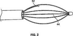
遠位電極バスケット44は、図2および図3にさらに詳細に見ることができる。遠位電極バスケット44は、露出区分の外側の領域で電気絶縁体材料50によりほんのわずかコーティングされるバスケットの脚48の露出区分から形成される電極46の形態のエネルギー放出要素を含む柔軟で弾力性のある楕円形状のバスケットである。遠位電極バスケット44はまた、電極46上、または隣接して配置される熱電対52の形態の温度検出要素を含む。熱電対52は、リード線54およびバスケットの脚の露出区分58または電極46に固定される熱電対終了点56を有する。 The
熱電対52のリード線54および電極46と電気通信している導体(図示せず)は、遠位バスケット44からハンドル36へ近接して、その後制御ケーブル38を通って近位連結器40に近接して伸びる。この構成により、電極46および熱電対リード線54は、ユーザーインターフェース表面16により制御器14を有するモジュラー配列において電気的に連結されることができる。エネルギー送出カテーテル18の近位連結器40を受け入れるよう構成されるインターフェース連結器20は、ユーザーインターフェース表面16に印刷されるエネルギー送出カテーテル18の実施態様の図式表示60に隣接して配置する。これはシステム10を設定しているユーザーに有用な可視プロンプトを提供する。近位連結器40がエネルギー送出カテーテル18のためにインターフェース連結器20に接続された時点で、電極46は直ちにRFエネルギー発生器12と電気通信し、RFが送出できない間に活性化状態と待機状態との間を行ったり来たりRF発生器12を切り替えてもよい制御器14による制御および変調の影響を受ける。さらに、熱電対52のリード線54はまた、制御器14と電気通信しているので、制御器14は、電極46に隣接している組織の温度を監視してもよい。この配列では、RFエネルギー発生器12、制御器14およびユーザーインターフェース16は、エネルギー送出カテーテル18へ活性化エネルギーを制御して送出するためのシステムを形成する。 A conductor (not shown) in electrical communication with
電極46単極または双極であってもよいが、しかしながら、電極46が単極の電極であるならば、対極板要素62は、RFエネルギー発生器12と患者(図示せず)との間の電気エネルギー放出または患者回路を完了するために、システム10とともに使用してもよい。対極板62には、導電パッド24、近位連結器64および導電パッド24と近位連結器64との間に伸び、これらの電気通信している導電性デーブル66が含まれる。導電パッド24は、患者の皮膚に取り外し可能に張り付けるよう構成され、またシステム10を使用する間、患者の皮膚に熱傷または他の損傷が導電パッド24の周辺に生じないよう十分大きな表面領域を備える導電性接着面を有してもよい。近位連結器64は、ユーザーインターフェース表面16上のインターフェース連結器28に連結するよう構成する。対極板62用のインターフェース連結器28は、ユーザーインターフェース表面16上の対極板62の図式表示68に隣接して配置する。前と同じように、これはシステム10を設定しているユーザーに有用な可視プロンプトを提供する。 The
エネルギー送出カテーテル18の近位連結器40および対極板62の近位連結器64が、ユーザーインターフェース表面16のそれぞれのインターフェース連結器20および28の経て制御器14に連結された時点で、RFエネルギーをRF発生器12によって生成する、すなわち、RF発生器12を活性化状態に切り替えてもよく、またエネルギー送出カテーテル18の遠位バスケット44の電極46から電極46に隣接している患者の標的組織に放出してもよい。処理部22はその後、熱電対52と処理部22との間のフィードバックループを経て、電極と隣接している組織の実質上一定温度を維持するために、RF発生器12の出力を調整してもよい。処理部22は、制御アルゴリズムを使用して、温度フィードバックを処理し、またRF発生器12用の制御信号を生成してもよい。さらに、制御アルゴリズムは、治療周期の実施態様用に所定の滞留時間または起動時間を設定するよう構成してもよい。本明細書に論じている制御装置および方法の実施態様と併せて使用してもよい制御アルゴリズムおよびシステム要素の実施態様は、「Control System and Process for Application of Energy to Airway Walls and Other Mediums」の表題で、2003年4月14日に出願された米国特許出願番号10/414,411号に見られる場合があり、これは参照することによりその全体が本明細書に組み込まれる。 When the
さらに、気管壁を治療するための装置および方法は、METHOD AND APPARATUS FOR TREATING SMOOTH MUSCLES IN THE WALLS OF BODY CONDUITS の表題で、1998年6月10日に出願された米国特許出願09/095,323号;MODIFICATION OF AIRWAYS BY APPLICATION OF ENERGYの表題で、2003年4月14日に出願された10/414,253;DEVICES FOR MODIFICATION OF AIRWAYS BY TRANSFER OF ENERGYの表題で、1999年11月8日に出願された09/436,455;METHOD FOR TREATING AN ASTHMA ATTACKの表題で、2001年10月25日出願された09/999,851;METHOD OF TREATING AIRWAYS IN THE LUNGの表題で、2004年3月26に出願された10/810,276;METHODS OF TREATING ASTHMAの表題で、2003年8月13日に出願された10/640,967;METHODS OF TREATING REVERSIBLE OBSTRUCTIVE PULMONARY DISEASEの表題で、2004年3月26日に出願された10/809,991;およびINACTIVATION OF SMOOTH MUSCLE TISSUE の表題で、2004年9月30日に出願された10/954,895;ならびにCONTROL SYSTEM AND PROCESS FOR APPLICATION OF ENERGY TO AIRWAY WALLS AND OTHER MEDIUMSの表題の米国特許6,411,852;およびDEVICES FOR MODIFICATION OF AIRWAYS BY TRANSFER OF ENERGYの表題の6,634,363に説明されている。上記のそれぞれは、参照することによりそれらの全体が本明細書に組み込まれる。 In addition, an apparatus and method for treating the tracheal wall is described in US patent application 09 / 095,323 filed June 10, 1998 under the title METHOD AND APPARATUS FOR TREATING SMOOTH MUSCLES IN THE WALLS OF BODY CONDUITS. No .: MODIFICATION OF AIRWYS BY APPLICATION OF ENERGY, filed 10 / 414,253 filed April 14, 2003; 09 / 436,455; METHOD FOR TREATING AN ASTHMA ATT 09 / 999,851 filed on Oct. 25, 2001 under the title of ACK; 10 / 810,276 filed March 26, 2004 under the title of METHOD OF TREATING AIRWAYS IN THE LUNG; METHODS OF TREATING
一実施態様では、RF発生器12は、標的組織温度を約60℃から約80℃、特に、約60℃から約70℃に維持するのに十分なワット出力を有する、約400kHzから約500kHzの周波数でのRFエネルギーを発生する。単一治療周期の実施態様のための活性化状態の持続期間は、約5秒から約15秒、特に、約8秒から約12秒であってもよい。あるいは、RF発生器の活性化状態の持続時間はまた、約150ジュールのエネルギーを標的組織へ送出するのに必要な持続時間、特に、約125ジュールのRFエネルギーを標的組織へ送出するのに必要な持続時間より多くならないよう設定してもよい。 In one embodiment, the
RF発生器12の活性化状態は、様々な装置および方法により開始を実施するが、しかしながら、図1の実施態様は、足踏みスイッチ26の形態でユーザー操作活性化スイッチを含む。導電性デーブル70は、足踏みスイッチ26と、ユーザーインターフェース表面16に配置される、それぞれのインターフェース連結器30に電気的に連結するよう構成される近位連結器72に連結し、またそれらの間に配置する。足踏みスイッチ26の近位連結器72用のインターフェース連結器30は、ユーザーインターフェース表面16上の足踏みスイッチ26の図式表示74に隣接して配置する。システム10のすべての要素が適切に機能して接続されているとすれば、足踏みスイッチ26は、RFエネルギー発生器12の活性化状態を開始するいくつかの構成に使用してもよい。これは準備完了状態に入る制御器と定義することができる。 The activation state of the
今から図4を参照して、ユーザーインターフェース表面16の実施態様のより詳細な図を示す。ユーザーインターフェース表面16は、図4に示すように実質上長方形で平面であってもよいが、他に適切な任意の形状、大きさ、または構成を有していてもよい。ユーザーインターフェース表面16は、いくつかの実施態様では、情報を伝達、またはそこから情報を受信するために、ユーザーがアクセスする、または見るエネルギー送出システムまたはその要素に任意の部分であってもよい。制御器14は、制御器14、あるいはユーザーインターフェース表面16のどこに位置してもよい交流(AC)電力のオン/オフスイッチを有してもよい。しかしながら、図4に示す実施態様では、ユーザーインターフェース表面16には、AC電力のオン/オフスイッチは含まれない。制御器14またはユーザーインターフェース表面16は、システム10の様々な可視指示器と併せて使用し、ユーザーにシステム10の様々な要素の状況を警告してもよい音声音発生器(図示せず)を含んでもよい。一実施態様では、音声音発生器には、制御器12の適切な任意の表面またはユーザーインターフェース表面16に取り付けてもよいスピーカー(図示せず)が含まれる。 Referring now to FIG. 4, a more detailed view of an embodiment of the
ユーザーインターフェース表面16は、ユーザーインターフェース表面16の左上隅の、多色のLED(発光ダイオード)準備完了指示器光76の形態の可視指示器を有する。RFエネルギー発生器12が、待機状態で使用できる状態にあると、準備完了指示器光76は、緑色などの第一の色により起動または点灯してもよい。エネルギー送出カテーテル18のエネルギー放出要素46へ送出されているRFエネルギーにより、待機状態または準備完了状態から活性化状態へRF発生器12が移行した時点で短い音声音もまた聞こえる時の活性化状態にRFエネルギー発生器12のスイッチが入ると、LED指示器76は、琥珀色などの第二の色により起動または点灯してもよい。さらに、離れているLED指示器92は、RFエネルギー送出の間に、青色などの第二の色により起動または点灯してもよい。ユーザーは通常、足踏みスイッチ26を押し下げる、また離すことにより治療周期用のRFエネルギー発生器12を始動する。起動周期の間、RFエネルギー発生器12を活性化状態から待機状態へ切り替える処理部22からの足踏みスイッチの遮断反応を引き起こすために、システム10の足踏みスイッチ26を再び押し下げ、また離すならば、準備完了指示器光76の色は、第一の色に戻るよう切り替えてもよい。音声音発生器が、一定の単一ピッチ音を送出していてもよい時間の間、システム10が、電源オン自己診断テスト(POST)形態のさなかにあるとき、第二の色または琥珀色はまた、準備完了指示器光76によって表示してもよい。さらに、壊れた電極46または壊れた熱電対52などのエネルギー送出カテーテル18の障害が制御器14によって検出される場合は、第二琥珀色はまた、準備完了指示器によって表示してもよい。エネルギー送出カテーテル18の障害を表示する第二の色の起動はまた、音声音発生器からの可聴式の第一エラー音と同時に起こってもよい。システム10が、可聴式の第一エラー音もまた生成する期間にシステム10を初期化するために、交流電力の循環を制御器14に実行しているときに、準備完了指示器光76は第一の色、緑を放ってもよい。基本的に、準備完了指示器光76は、システム10の使用準備ができたとき第一の色を放出し、またシステム10がシステム10に障害を検出し、使用準備ができていないならば第二の色または琥珀色を放出する。 The
以下のLED準備指示器76は、ユーザーインターフェース表面16で印刷される足踏みスイッチ26の図式表示74である。足踏みスイッチ26の図式表示74は、足踏みスイッチ26アセンブリの近位連結器72を受け入れるよう構成されるインターフェース連結器30の真上にあり、またそれに隣接している。足踏みスイッチ26用のインターフェース連結器30に隣接している足踏みスイッチ26の図式表示74は、システム10の設定をする間、足踏みスイッチ26用に適切なプラグを位置付けるために、ユーザーに直観的でユーザーフレンドリーなプロンプトを提供する。 The following
導電パッド24、導電性デーブル66および近位連結器64を含み、ユーザーインターフェース表面16で印刷される対極板アセンブリ62の図式表示68が足踏みスイッチ26の図式表示74の右側にある。対極板アセンブリ62の近位連結器64の図式表示78は、対極板アセンブリ62の近位連結器64のためにインターフェース連結器28の真上にあり、またそれに隣接して配置する。琥珀色LED光80の形態の可視指示器は、対極板アセンブリ62の導電パッド24の図式表示82内で、ユーザーインターフェース表面16上に配置する。システム10が、さらに音声音発生器からの単一ピッチの可聴音と同時に起こってもよいPOSTにより開始している場合は、可視指示器80は、定常状態で点灯するよう構成してもよい。制御器14が、RFエネルギー発生器を活性化状態に起動するよう3回以上試みた後で、所定の値より高い患者回路でインピーダンスを測定する場合は、可視指示器80はまた、起動および点灯してもよい。第二エラー音は、この状況においては可視指示器の起動と同時に発生してもよい。いくつかの実施態様では、患者回路のための所定のインピーダンス値は、約1000オームを超え、特に、約900オームを超えてもよい。患者回路におけるかかる高インピーダンス測定は、開回路を表示し、またユーザーが患者回路を調査し、別の時にシステム10を試みることを要求する。患者回路には、エネルギー送出カテーテル18の電極46および導電性デーブル38、患者の身体と電気通信している導電パッド24および電極46を付けた患者(図示せず)、および対極板アセンブリ62が含まれる。第一可聴エラー音もまた音声音発生器によって生成する期間に、ユーザーに交流電力を一旦切ってすぐに入れなおすことを要求する障害が、処理部22によって起きた場合には、可視指示器80はまた、点滅形態で起動または点灯してもよい。 A
対極板62の図式表示68の右側には、エネルギー送出カテーテル18の図式表示60がユーザーインターフェース表面16で印刷されていて、ハンドル36、細長い軸34および遠位電極バスケット44を含む。エネルギー送出カテーテル18の近位連結器40を受け入れるよう構成されるインターフェース連結器20は、エネルギー送出カテーテル18のハンドル36の図式表示84に隣接して真下に配置する。琥珀色LED光86の形態の第一可視指示器は、ユーザーインターフェース表面16上の遠位電極バスケット44の図式表示88内に配置する。第一可視指示器と異なる第二の色を有し、赤いLED光90の形態の第二可視指示器90は、ハンドル36の図式表示84内に配置する。 On the right side of the
制御器14が所定の値より高い患者回路でのインピーダンスを測定する場合は、システム10のいくつかの実施態様では、第一可視指示器86は起動および点灯してもよい。いくつかの実施態様では、患者回路の所定のインピーダンス値は、約1000オームより高く、特に、約900オームより高くてもよい。第一可聴エラー音はまた、かかる起動の間に生成してもよい。患者回路の測定されるインピーダンスが、RFエネルギー発生器12を活性化状態に起動するよう少なくとも3回以上試みる間に、かかる所定の値より高くなる場合は、第一可視指示器86はまた、点灯または起動してもよい。この状況では、第二可聴エラー音はまた、第一可視指示器86の起動と併せて生成してもよい。システム10の処理部22が、さらに音声音発生器からの単一ピッチの可聴音と同時に起こってもよいPOSTにより開始している場合は、第一可視指示器86はまた、定常状態で点灯してもよい。第一可聴エラー音もまた音声音発生器によって生成する期間に、ユーザーに交流電力を一旦切ってすぐに入れなおすことを要求する障害が、処理部22によって起きた場合には、可視指示器86はまた、点滅形態で起動または点灯してもよい。 In some implementations of the
壊れた電極46または壊れた熱電対52などのエネルギー送出カテーテル18の障害が制御器14によって検出される場合は、第二可視指示器90は、点灯形態または間欠形態で起動または点灯してもよい。エネルギー送出カテーテル18の障害を示唆する第二可視指示器90の起動はまた、音声音発生器からの可聴式の第一エラー音と同時に起こってもよい。システム10の処理部22が、さらに音声音発生器からの単一ピッチの可聴音と同時に起こってもよいPOSTにより開始している場合は、第二可視指示器90はまた、定常状態で点灯してもよい。第一可聴エラー音もまた音声音発生器によって生成する期間に、ユーザーに交流電力を一旦切ってすぐに入れなおすことを要求する障害が、処理部22によって起きた場合には、第二可視指示器90はまた、点滅形態で起動または点灯してもよい。 If a failure of the
放射電極の図式表示の形態の別の可視指示器92は、ユーザーインターフェース表面16上の配置する。RFエネルギー発生器12が活性化状態に切り替わり、RFエネルギーをエネルギー送出カテーテル18へ送出する期間に、第三の色または青色LEDであってもよいこのRFエネルギー指示器92は、点滅形態で起動または点灯してもよい。システム10の処理部22が、さらに音声音発生器からの単一ピッチの可聴音と同時に起こってもよいPOSTにより開始している場合は、RFエネルギー指示器92はまた、定常状態で点灯してもよい。第一可聴エラー音もまた音声音発生器によって生成する期間に、ユーザーに交流電力を一旦切ってすぐに入れなおすことを要求する障害が、処理部22によって起きた場合には、RFエネルギー指示器92はまた、点滅形態で起動または点灯してもよい。 Another
デジタル表示部94は、RFエネルギー指示器92の下のユーザーインターフェース表面16に配置し、数値情報を表示するよう構成する。デジタル表示部94は、ユーザーインターフェース表面16上のデジタル表示部94の真下に配置されるスイッチ96によって制御し、またはさもなければ初期化する。標準的な形態では、デジタル表示部94は、システム10のユーザーによって実行されるシステム10によって送出される成功した治療周期の数を表示することになる。スイッチ96が約2秒から約4秒より短く押し下げるならば、不成功になった、または完了していない治療周期の数は、約5秒など、短時間に表示される。この短時間の後、デジタル表示部94は、完了した治療周期の数の表示に戻る。スイッチ96を押し下げ、約2秒から約4秒の短時間より長く維持する場合は、デジタル表示部94は、約1秒など、短時間「0」を示す。この短い1秒の間スイッチ96を押し下げて維持するならば、完了した、および完了していない治療周期の総数は0に初期化される。この短い1秒の間スイッチ96を離すならば、デジタル表示部94は、治療周期の計数器を初期化することなく、完了した、または成功した治療周期の表示を戻す。 A digital display 94 is disposed on the
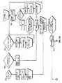
図5を参照すると、様々なシステム工程の実施態様をフローダイヤグラムの形式で示している。使用に当たり、治療エネルギーを送出するためのシステム10は、上述のように、制御器14またはユーザーインターフェース表面16上のスイッチ(図示せず)によって実施してもよい、などの、電力を最初に供給する。ひとたび交流電力が制御器14に供給されると、処理部22は、処理部22、制御器14およびシステム10の略完全性を検証する、ボックス100によって表示されるPOST周期を開始する。POSTが不合格ならば、ユーザーは、制御器14、特に、制御器14の処理部22を再起動するために、交流電力の循環を開始する。さらに、ひとたび交流電力が制御器14に供給されると、処理部22は、決定点「訂正できない誤り」102によって表示される第一背景アルゴリズムを継続的に起動する。訂正できない誤りの検査は、CPU設定、COPタイムアウト、ROMCRCエラー、RAM、不法CPU命令、ソフトウェア、非揮発性メモリ、RF電流計測エラーなどのハードウェアおよびプロセッサのエラーに関して点検する。かかるエラーが検出されるならば、ユーザーは、制御器14、および特に、制御器14の処理部22を再起動するために、ボックス111によって表示するように、交流電力の循環を開始すべきである。交流電力の循環の間、ユーザーは、デジタル表示部94の点滅および同時発生の可聴エラー音と同様に、ユーザーインターフェース表面16上のすべての可視指示器の点滅によって循環状況を通知されることになる。 Referring to FIG. 5, various system process embodiments are shown in the form of a flow diagram. In use, the
POSTが成功したならば、処理部22は、決定点104によって表示するように、エネルギー送出カテーテル18、対極板62および足踏みスイッチ26などのシステム要素のすべての接続が、ユーザーインターフェース表面16のそれぞれのインターフェース連結器20、28および30とすべて適切に連結されているかどうか決定する試験アルゴリズムを開始することになる。このお決まりの手順の間にエラーが検出されるならば、準備完了指示器光76は、第二または琥珀色状態を維持することになり、RFエネルギー発生器12は準備が完了しておらず、または待機状態であることを表示する。エネルギー送出カテーテル18、対極板62および足踏みスイッチ26などのシステム要素が、ひとたびユーザーインターフェース16と適切に連結されると、処理部22は、エネルギー送出カテーテル18の温度検出要素または熱電対52が、ボックス106によって表示するように適切に機能しているかどうか決定するアルゴリズムを開始する。 If POST is successful, the
この試験の間、処理部22は、熱電対52によって表示する温度を測定し、またいくつかの実施態様のための室温を含む所定の温度範囲とその結果を比較する。例えば、いくつかの実施態様のための所定の温度範囲は、約15℃から約35℃、特に、約20℃から約30℃であってもよい。熱電対52によって表示される、測定された温度が所定の温度範囲内に入らない場合、処理部22は、エネルギー送出カテーテル18の図式表示60のハンドル84での赤色のLED第二可視指示器90の点滅形態起動を開始することに加え、準備完了指示器光76を第二の色または琥珀色に切り替えることを含むエラーメッセージをユーザーに開始することによって壊れた熱電対52を表示する。可聴エラー音はまた、可視指示器76および90によって生成されるエラーメッセージと同時に生じてもよい。これらのエラーメッセージは、ユーザーに、エネルギー送出カテーテル18を新しいものと取り替える必要がある可能性があることを通知する。 During this test, the
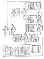
ひとたび熱電対試験が成功して実行されると、処理部22は、準備完了指示器光76を第一の色または緑色に切り替え、ボックス108によって表示するように、システム10が、患者において治療周期を実行するのに現在準備完了となったことを示す。この時点で、少なくとも1つの放出要素または電極46を、患者の気管支気道の平滑筋などの患者の標的組織に隣接して配置するように、ユーザーはその後、エネルギー送出カテーテル18の遠位電極バスケット44を位置付けてもよい。ひとたび電極46が適切に位置付けられると、ユーザーアクション/入力ボックス110によって表示するように、ユーザーは足踏みスイッチ26を押し下げ、治療周期を開始する。足踏みスイッチ26を押し下げた時点で、処理部22は患者回路のインピーダンスを直ちに測定し、インピーダンスが所定の最高値を下回る、または所定のインピーダンス範囲内にあるならば、処理部22はRFエネルギー発生器12を準備完了または待機状態から活性化状態へ切り替え、ここでRFエネルギーは、治療周期を開始するために患者の標的組織に送出されている。 Once the thermocouple test has been successfully performed, the
標準的な治療周期のいくつかの実施態様では、結果ボックス112によって表示するように、処理部22および処理部22によって実行されるアルゴリズムは、約5秒から15秒まで、特に、約8秒から約12までの滞留時間の間、RFエネルギー発生器12を活性化状態に維持するよう構成する。治療周期の継続時間はまた、前記周期の間に標的組織に送出される総合エネルギーによって抑制される。例えば、処理部22は、標的組織へ送出される総合エネルギーが最大約150ジュール、特に、最大約125ジュールになると治療周期を終了するアルゴリズムを実行してもよい。治療周期の間、処理部22は、標的組織の実質上一定温度を維持するために、RFエネルギー発生器12の出力を制御する。治療周期の実施態様の間の標的組織の温度は、約60℃から約80℃、特に、約60℃から約70℃の温度に維持してもよい。上述のように、処理部22は、温度測定要素または熱電対52によって標的組織の温度を監視することによって、また測定温度が望ましいものより高いならばRFエネルギー発生器12の出力を縮小させ、測定温度が望ましいものより低いならばRFエネルギー発生器の出力を増大させるフィードバックループにて温度情報を処理することによって、標的組織の実質上一定温度を維持することができる。 In some implementations of a standard treatment cycle, as displayed by the result box 112, the
治療周期の間、処理部22は、青色のRFエネルギー可視指示器92を活性化した同一色形態または点滅形態に切り替えることになり、また音声単一発生器を起動して、治療周期の間の高ピッチ、次に低ピッチの可聴音を反復する可聴音発生器からデュアルピッチの可聴音、続いて成功した周期の終わりに長いシングルピッチ音を生成することになる。治療周期の最中にエラーが発生したならば、可聴エラー音が生じ、エラーを示す可視指示器または指示器は、上述のように起動する。上述のように、治療周期はまた、ユーザーアクションボックス114によって表示するように、治療周期の間にユーザーが足踏みスイッチ26を押し下げることによって中断し、足踏みスイッチの遮断を開始してもよい。ユーザーが、何らかの理由でシステム10が不適切に動再していると感じるならば、ユーザーが、電極46の場所が不適切であると感じるならば、または他のどんな理由によってでもこれを行ってもよい。ユーザーによる足踏みスイッチの遮断アクションは、ボックス108によって表示する、システム10をRF発生器準備完了状態に戻すが、デジタル表示部94での完了した、または成功した治療周期の記録を取らない。治療周期が成功して完了するならば、デジタル表示部94は、総数「1」を表示し、成功して完了した1つの治療周期を表示する。 During the treatment cycle, the
治療周期の間にエラーが発生するならば、結果ボックス116に表示するように、足踏みスイッチ遮断オプションが使用され、引き続き「0」が表示される。しかしながら、約2秒から約4秒より長く表示部制御スイッチ96を押し下げるならば、デジタル表示部94は「1」を示し、完了していない、または不成功に終わった1つの治療周期を示す。ユーザーは、継続してエネルギー送出カテーテル18を患者の生体構造内の新しい場所に配置し、治療周期の望ましい回数だけRFエネルギー発生器12を活性化状態に起動してもよい。治療周期の間にエラーが発生するならば、結果ボックス116に表示するように、ユーザーインターフェース16は間もなく、適当な可視指示器および可聴音指示器によって発生してエラーのタイプを表示し、またユーザーに行動方針を提言する。ユーザーが修正を試みた後で、ユーザーアクション/入力ボックス118によって表示するように、別の治療周期を開始するために、足踏みスイッチ26を再び押し下げてもよい。 If an error occurs during the treatment cycle, the foot switch cutoff option is used to display in the
足踏みスイッチ26を押し下げた時点で、患者回路のインピーダンスが所定の最高値より高い、または所定のインピーダンス範囲内にないならば、結果ボックス120に表示するように、可視指示器および可聴音を含む2つにエラーメッセージのうちの1つは、システム10によって作成してもよい。特に、足踏みスイッチ26の第一の押し下げまたは足踏みスイッチ26の第二の押し下げが行われた時点で、ハイインピーダンスが測定されるならば、ボックス122によって示すように、エラーメッセージ「配置を改善して継続してください」が上述のように生成され、それによりユーザーインターフェース16上の遠位バスケット図式88の琥珀色の可視指示器86は起動および点灯し、また第一エラー音は可聴音発生器によって生成される。さらに、完了していない治療周期は、デジタル表示部94によって記録を取られる。ひとたび修正が試みられると、ユーザーアクション/入力ボックス124によって表示するように、治療周期を再開する場合に足踏みスイッチ26を再び押し下げてもよい。 When the
第三の、または次の足踏みスイッチ26の押し下げの時点で、同じエラーがシステム10によって検出されるならば、上述のように、「患者回路を調査してください」のエラーメッセージが生成され、それによりユーザーインターフェース表面16上の対極板図式82の琥珀色の可視指示器80および電極バスケット図式88の琥珀色の可視指示器86は起動および点灯する。かかるエラーメッセージはまた、可聴音発生器によって生成される第二可聴エラー音と同時に生じる。さらに、完了していない治療周期は、デジタル表示部94によって記録を取られることになる。エラーの修正を試みた後、ユーザーアクション/入力ボックス126によって示すように、別の治療周期を開始するために足踏みスイッチ26を再び押し下げてもよい。 If the same error is detected by the
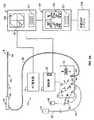
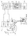
図6Aは、本明細書に説明するシステム10のシステム概略図を示す。システムは、治療情報、治療パラメータ、仮想地図、位置付け、または開業医にとって有用な他のデータを表示するために、いくつでも画像表示部130を有してもよい。例えば、多くの内視鏡的処置には、標的部位(および一部の例では、治療装置18の先端)の実時間画像を示す、少なくとも1つの画像表示部130が含まれる。地図は、示すように仮想表示部132のために別個のモニタに映してもよい。 FIG. 6A shows a system schematic diagram of the
仮想表示部132は、装置の全体の仮想地図、仮想治療場所、または仮想場所を備えてもよい。あるいは、2つの表示部130および132を組み合わせてよいので、仮想表示部は、画像表示部に重ね合わせられる、または画像表示部の側面に沿って配置される。しかしながら、地図はまた、表示部130または132のどちらかで数値形式(例えば、位置付け情報131の表示部など)で示してもよい。画像表示部130は、内視鏡的装置(肺気管支鏡装置の場合は)に関連しているどんな型であってもよいことが留意されるべきである。さらに、画像表示部は、代替の実時間画像表示部(例えば、蛍光透視鏡の、または無侵襲の実時間画像化手段)であってもよい。装置の別の変化物では、地図は、制御器14のユーザーインターフェース16に組み込んでもよい。 The
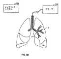
本明細書の説明しているシステムおよび方法には、図6Bに示すレンダリングシステムを使用してマッピングされている臓器の少なくとも一部または臓器組織網(この場合は肺2)の地図を作成することが含まれる。地図を作成することは、コンピュータ断層撮影(CT)、磁気共鳴映像法(MRI)、陽電子放射断層撮影法(PET)、超音波イメージング、または類似している他のレンダリングシステムを含むレンダリングシステム128を使用することを含んでもよい。レンダリングシステムは、図式的地図/仮想地図または身体のある場所における固定基準点に対する単なる一連の配位であってもよい地図を作成してもよい。 The systems and methods described herein include mapping a map of at least a portion of an organ or organ tissue network (in this case, lung 2) that is mapped using the rendering system shown in FIG. 6B. Is included. Creating a map includes a
例えば、図6Bに示すように、レンダリングシステム128は、身体の外部にあるシステムであってもよい(CT、MRI、PETなどのように)。あるいは、レンダリングシステムは、プローブまたは他の要素129を有してもよく、ここでは追跡システムは、臓器を通って進むにつれてプローブ/装置(最終的にデータはいくつかの保存装置に記録してもよい)のデータまたは配位を作成する。このような場合には、地図のデータが表示部での仮想地図に示されるまで、地図はデータだけから構成される。かかる地図は、図1に示すもののような図式表示部を有することのないシステムで使用することになる。代わりに、これらのデータだけの地図は、ユーザーインターフェース16、発生器12、または制御器14と一体化して、例えば、技師がすでに特定の領域において治療したかどうかを表示するために、治療活動の間に単純な信号(可聴、可視、またはその他)を送る。 For example, as shown in FIG. 6B, the
表示部130および132はまた、様々な情報131(これまでにその場所に治療が施されたかどうか、治療パラメータなどのような)を提供するのに使用してもよい。さらに、情報131はまた、ユーザーインターフェース16(以下に説明するように)からの情報を含むことにより、開業医がユーザーインターフェース16から表示部130または132へ焦点を常に移す必要性を除く。図6Aは、発生器および制御器に接続される画像表示部を示すが、いくつの構成でも可能である。それらは例示だけの目的で示す。 The
地図は患者の治療に先立ちレンダリング/構築してもよく、または患者を治療している時にレンダリングしてもよい。例えば、CT装置は、治療装置と同じ手術室で利用できない可能性がある。それ故に、開業医はレンダリングシステムを使用して、後に予定してある処置に使用するために地図を作成してもよい。 The map may be rendered / constructed prior to patient treatment or may be rendered as the patient is being treated. For example, a CT device may not be available in the same operating room as a treatment device. Therefore, the practitioner may use the rendering system to create a map for use in a later scheduled procedure.
本発明の一変化物では、図6Cに示すように、ひとたび地図がレンダリングされると、それは臓器組織網での1つ以上の場所と相関し、および/または正しく位置付けられる。この相関関係は地図データと実際の身体的部位とを一致させる。地図を正しく位置付ける1つの方法は、装置18を肺の中へ入れて、分かっている場所に進ませることである(例えば、主気管支142の第一分岐)。ひとたび装置18が適切な位置になると、その後ユーザーは位置決めシステム138を使用して、部位の仮想画像(図6Aに示すように)を実際の部位に正しく位置付ける。いくつかの部位に対してこれを反復してもよい。 In one variation of the invention, as shown in FIG. 6C, once the map is rendered, it correlates and / or is correctly positioned with one or more locations in the organ tissue network. This correlation matches the map data with the actual physical part. One way to correctly position the map is to place
図6Cに示すように、仮想画像136は気道の仮想地図を示す。装置18が臓器に進むにつれて、装置18での位置決め器具(図示せず)は位置決めシステム138と伝達し、装置の領域位置を設ける。仮想地図が臓器の実際の構造と相関する限り、装置18の正確な仮想位置は仮想地図上に表示することができる。本明細書に説明したように、装置18を肺2での治療に適用する時に、開業医はシステム10または表示部130、132で治療パラメータおよび/または場所を見てもよい。 As shown in FIG. 6C, the
図6Dは、装置18と連結する位置決め器具140の一例を示す。位置決め器具140は位置決めシステム138に伝達し、臓器内で移動している最中に装置18を追跡する。かかる位置決め器具およびシステムの例は、上記を参照することによって引用される、および組み込まれる参考文献に見られる。 FIG. 6D shows an example of a
さらに、治療パラメータがそれぞれの治療部位と関連付けられ、患者の治療履歴プロファイルを作成するように、治療システム10、画像表示部130、仮想表示部132、および/または位置決めシステム138はお互い連結してもよい。当然ながら、この情報は、制御器14、位置決めシステム138、またはシステムの他のどんな要素内でも電子的に記録してもよい。前回のこの治療履歴プロファイルは、次の治療活動に使用するための取り込んでもよい。コンピュータシステムもしくは制御器のメモリ、または単独型もしくはシステムのどんな要素にも統合されてもよいレンダリングシステムにさえも、電子的に治療履歴プロファイルを保存することは望ましい場合がある。 Further, the
パラメータは、治療の時間帯または継続期間、温度(部位、装置、または隣接している部位などの)、エネルギー、電力、平均電力、状況/完了していない起動、治療の場所、印加された総合エネルギー、温度変化率、印加されたエネルギー変化率、治療場所のインピーダンス、またはそれらの組み合わせを含んでもよい。本明細書に留意するように、かかるパラメータは治療場所にマッピングしてもよい。パラメータおよび可能性のある組み合わせは、上に記載の特許で論じているこれらのパラメータを含んでもよいことが留意される。 Parameters include treatment time period or duration, temperature (such as site, device, or adjacent site), energy, power, average power, status / incomplete activation, treatment location, total applied It may include energy, rate of change of temperature, applied rate of change of energy, impedance of treatment site, or combinations thereof. As noted herein, such parameters may be mapped to treatment locations. It is noted that the parameters and possible combinations may include those parameters discussed in the patents described above.
本明細書に説明しているシステムおよび方法の利点により、複数の場所での治療または反復治療が必要な臓器での治療を改善することができる。例えば、本明細書に説明するように、治療履歴プロファイルを作成する、またパラメータデータを提示することにより、開業医は、治療場所の重複または特定の場所の余分な治療を場合によっては回避することができる。本発明の変化物では、地図および関連するパラメータが、装置が前回に治療した場所にあると表示したならば、治療システムは、特定の部位に療法を施すのを防止するよう構成してもよい。そのような場合には、適切な音声または可視信号が表示部130、132のどちらに示されることになる。 The benefits of the systems and methods described herein can improve treatment in organs that require treatment in multiple locations or repeated treatments. For example, as described herein, by creating a treatment history profile and presenting parametric data, a practitioner may sometimes avoid duplication of treatment locations or extra treatment at specific locations. it can. In a variation of the present invention, if the map and associated parameters indicate that the device is at the place where it was last treated, the treatment system may be configured to prevent a particular site from being treated. . In such a case, an appropriate sound or visible signal is displayed on either of the
付加的な利点は、望ましい間隔で治療部位に間隔をあけること、および装置が適切な場所にあることに関して開業医に信号を発することを含む。また、本発明のシステムによりさらに、開業医が治療すべき次の領域を表示するよう進む最短距離を計算することによって治療計画が可能となる。これを達成するために、システム10は、表示部130、132に適切な指示を与えてもよい。例えば、図6Eは、仮想表示部132の変化物を例示する。表示された情報131は、単なる例であることを意図している。本発明の変化物は、本発明に論じたパラメータのいずれの表示部でも含む。 Additional advantages include spacing the treatment site at a desired interval and signaling the practitioner regarding the device being in place. The system of the present invention also allows treatment planning by calculating the shortest distance traveled by the practitioner to display the next region to be treated. To achieve this, the
図6Eに示すように、仮想地図136は、臓器を通って前進するにつれて装置18の進行を追跡することができる仮想地図136はまた、治療済み領域(例えば影部分146)を未治療部分から視覚的に区別することもできる。また、仮想地図136は、視覚的情報を提供して次の部位に開業医を案内することができる。(例えば矢印148を介して)。また、仮想地図136は、装置18の位置に基づいてパラメータに関する情報131を提示することができる。例えば、影部分18へ移動すると、そのような治療パラメータ関する情報が表示される。 As shown in FIG. 6E, the
システムは、ユーザーが、どこにいるのか、どこにいたのか、および異なる位置において何を行ったかについての情報を得ることができるようにする。さらに、不十分に治療された領域から保護するために、装置の第二パスは、地図および位置決め情報と組み合わされると、治療されなかった、または不十分に治療された領域の評価を可能にする。システムは、実際の治療が「理想処置」と比較される治療後分析を可能にすることができる。 The system allows the user to get information about where they are, where they were, and what they did at different locations. Furthermore, in order to protect against poorly treated areas, the second pass of the device, when combined with a map and positioning information, allows the evaluation of untreated or poorly treated areas . The system can allow post-treatment analysis where the actual treatment is compared to the “ideal treatment”.
いくつかの変化物において、制御器および/または電源は、開業医が無意識に部位を二度治療しようとしていることを地図治療履歴プロファイルが示すと治療を提供することができなくなるように、構成することができる。いくつかの変化物において、システムは、聴覚信号と組み合わされて現在の治療場所と治療履歴プロファイルとの間の関係を示すことができる。例えば、聴覚信号は、治療が不完全/すでに行われていた場合に警告音を出すことができ、位置決め器具が特定部位を通過するたびに、同じ信号が引き起こされる。
治療はまた、地図の分析またはその他の解剖学的データの分析に基づいて滴定することもできる。例えば、地図が様々な壁厚を有する臓器を生じると、アルゴリズムを使用して治療のパラメータを調整することができる(例えば、より厚い壁の部分がより高いエネルギー治療を受け、より薄い部分がより低いエネルギーを受ける。)滴定は、目的とする対象が存在する深さに基づくことができる。例えば、平滑筋組織が臓器壁の内側の奥に位置する場合、滴定は最適な治療のためにエネルギーパラメータを調整することができる。別の例において、対象領域が他の重要臓器と近接していることをマッピングまたはその他の分析が示すと、エネルギーパラメータを軽減することができる。In some variations, the controller and / or power supply may be configured so that a medical treatment profile cannot provide treatment if the practitioner is unconsciously trying to treat the site twice Can do. In some variations, the system can be combined with the auditory signal to indicate the relationship between the current treatment location and the treatment history profile. For example, the auditory signal can beep when the treatment is incomplete / already done and the same signal is triggered each time the positioning device passes a particular site.
Treatment can also be titrated based on analysis of the map or other anatomical data. For example, if the map yields organs with varying wall thicknesses, algorithms can be used to adjust treatment parameters (e.g., thicker wall portions receive higher energy treatments and thinner portions become more Receives low energy.) Titration can be based on the depth at which the target object is present. For example, if smooth muscle tissue is located deep inside the organ wall, titration can adjust the energy parameters for optimal treatment. In another example, energy parameters can be reduced when mapping or other analysis indicates that the region of interest is in close proximity to other vital organs.
本発明のシステムはまた、治療される臓器または領域の可視識別も提供することができる。例えば、部位がすでに治療されている場合、臓器を特定の色で示すことができ、治療されていない領域に信号を送るために、対象臓器を他の色で示すことができる。特定部位を次に治療すべきであるとシステムが決定する場合、この推奨治療場所もまた画像表示部130、132上で視覚的に区別することが出来る。 The system of the present invention can also provide visual identification of the organ or area to be treated. For example, if the site has already been treated, the organ can be shown in a particular color, and the target organ can be shown in another color to send a signal to an untreated area. If the system determines that the particular site should be treated next, this recommended treatment location can also be visually distinguished on the image display 130,132.
システムはまた、地図に基づく理想処置または処置プロファイルの作成も可能にすることができる。例えば、地図の使用は、様々な特徴が対象領域または臓器について決定されることを可能にすることができる(例えば、通路の直径、平滑筋組織の量、分岐点など)。これらの特徴に基づいて、エネルギー治療は、一式の理想パラメータに対して調整することができる。従って、開業医は実際の治療のパラメータ(治療履歴プロファイルを使用する)を、理想処置に基づく理想パラメータと比較することができる。不一致の場合、開業医には、領域を再治療するか、または実際の治療が理想的治療と異なる領域を単に観察する選択肢がある。理想パラメータは、上述のようなパラメータと同じ種類にすることができる。例えば、それらは理想的治療時間、理想的温度、理想的エネルギー、理想的温度変化率、理想的エネルギー変化率、治療場所の理想的インピーダンス、およびその組み合わせを含むことができる。
システムは、処置中または処置後に起こり得る実際の処置との理想処置の比較を可能にすることができる。The system can also allow creation of ideal treatments or treatment profiles based on maps. For example, the use of a map can allow various features to be determined for a region or organ of interest (eg, passage diameter, amount of smooth muscle tissue, bifurcation points, etc.). Based on these characteristics, the energy treatment can be adjusted for a set of ideal parameters. Thus, the practitioner can compare actual treatment parameters (using a treatment history profile) with ideal parameters based on the ideal treatment. If there is a discrepancy, the practitioner has the option of retreating the area or simply observing the area where the actual treatment differs from the ideal treatment. The ideal parameters can be of the same type as the parameters described above. For example, they can include ideal treatment time, ideal temperature, ideal energy, ideal rate of change of temperature, ideal rate of change of energy, ideal impedance of treatment location, and combinations thereof.
The system can allow comparison of ideal treatment with actual treatment that may occur during or after treatment.
上記のように、地図は改善された治療のために、身体および対象領域を取り囲む構造の分析を可能にすることができる。一例において、システムは、解剖学的特徴に対して調整された療法を行うことができるように、身体を分析して治療されている領域の解剖学的特徴を決定するためのアルゴリズムを使用することができる。例えば、解剖学的特徴は、管腔通路直径、臓器の分岐点、平滑筋組織の深さ、平滑筋組織の量、臓器の肉厚、離れた臓器と比べた臓器の近接性、臓器の周辺、臓器内の流体の程度、臓器内の襞の数、臓器内の上皮または内皮層の状態、臓器内の流量、臓器内の付加的組織の存在、血管の存在、軟骨の存在、および平滑筋が刺激された時の収縮の程度を含むことができる。そのような解剖学的特徴は、図6Cに示すように地図のレンダリング中に識別することができる。 As described above, the map can allow analysis of structures surrounding the body and the area of interest for improved treatment. In one example, the system uses an algorithm to analyze the body and determine the anatomical features of the area being treated so that the therapy can be tailored to the anatomical features. Can do. For example, anatomical features include luminal passage diameter, organ bifurcation, smooth muscle tissue depth, smooth muscle tissue volume, organ wall thickness, organ proximity compared to distant organs, organ periphery The degree of fluid in the organ, the number of sputum in the organ, the state of the epithelium or endothelial layer in the organ, the flow rate in the organ, the presence of additional tissue in the organ, the presence of blood vessels, the presence of cartilage, and smooth muscle It can include the degree of contraction when is stimulated. Such anatomical features can be identified during map rendering as shown in FIG. 6C.
理想処置の作成は別として、処置は、地図上で識別される特定の解剖学的特徴に応じて実時間基準で調整することができる。治療装置が実際の治療部位に設置されると、このシステムは制御システムを始動させて、エネルギーまたはその他のパラメータのうちの1つ以上に警告する。 Apart from creating an ideal treatment, the treatment can be adjusted on a real-time basis depending on the specific anatomical features identified on the map. When the treatment device is installed at the actual treatment site, the system activates the control system to alert one or more of energy or other parameters.
地図は三次元地図になるよう構成することができることに留意すべきである(例えば、多くの方向にある気管支通路の分岐は、適切な画像化のために三次元地図を必要とする。)あるいは、単一面の地図を作成するのみを所望することもできる。 It should be noted that the map can be configured to be a 3D map (eg, bronchial passage branches in many directions require a 3D map for proper imaging). It can also be desired to only create a single-sided map.
本発明の別の変化物において、本説明書で説明される上記システムの側面は、エネルギー療法を治療場所に適用するために使用されるエネルギー送出部を有する装置と組み合わせることができ、その場合、治療装置は臓器組織網を通って前進しながら情報をレンダリングシステムに伝達して地図の少なくとも一部を作成する。そのような場合、レンダリングシステムは身体内の装置の動きを単に追跡することができる。例えば、装置は光学追跡装置(光学コンピュータマウスなど)において使用されるものと同様な感知器アセンブリを備えることができる。この方法において、地図は治療が進行するにつれてレンダリングされる。 In another variation of the invention, the aspects of the system described in this document can be combined with a device having an energy delivery portion that is used to apply energy therapy to a treatment location, where As the treatment device advances through the organ tissue network, it transmits information to the rendering system to create at least a portion of the map. In such a case, the rendering system can simply track the movement of the device within the body. For example, the device can comprise a sensor assembly similar to that used in an optical tracking device (such as an optical computer mouse). In this method, the map is rendered as treatment progresses.
例えば、治療装置上の、またはそれに接続される感知器アセンブリは、レンダリングシステムと通信し、地図の一部を作成するよう臓器内の装置の動きの検出を可能にすることができる。一変化物において、図6Dの140によって示されるような感知器アセンブリは、発光源、感知器、およびデジタル信号処理部を備え、発光源は感知器へと臓器壁に光を反射し、感知器は複数の画像、強度、および/または反射光の波長を比較することによって装置の動きを決定するデジタル信号処理部へ伝達する。例として、発光源は発光ダイオードを備えることができ、感知器は相補型金属酸化膜半導体(CMOS)を備えることができる。しかしながら、いずれの既知の構造を使用してもよい。いくつかの変化物において、構造は、装置が臓器組織網を通って前進するにつれて追跡を可能にすることができる。感知器アセンブリの設置の例は、図6Cで見ることができる。ほとんどの場合、感知器アセンブリおよび位置決め器具は装置の遠位端にある。 For example, a sensor assembly on or connected to the treatment device can communicate with the rendering system and allow detection of the movement of the device within the organ to create a portion of the map. In one variation, the sensor assembly as shown by 140 in FIG. 6D comprises a light source, a sensor, and a digital signal processor, the light source reflecting light back to the organ wall to the sensor, Communicates to a digital signal processor that determines device movement by comparing multiple images, intensities, and / or wavelengths of reflected light. As an example, the light emitting source can comprise a light emitting diode and the sensor can comprise a complementary metal oxide semiconductor (CMOS). However, any known structure may be used. In some variations, the structure can allow tracking as the device is advanced through the organ tissue network. An example of the installation of the sensor assembly can be seen in FIG. 6C. In most cases, the sensor assembly and positioning tool are at the distal end of the device.
三次元地図を作成することが困難な場合において、治療装置は、外部位置決めシステムと通信する少なくとも1つの位置決め器具をさらに含み、地図の一部を作成して三次元構成を可能にする。 In cases where it is difficult to create a three-dimensional map, the treatment device further includes at least one positioning device in communication with an external positioning system to create a portion of the map to enable a three-dimensional configuration.
本発明のさらにもう1つの変化において、本発明は、それぞれ管腔通路を有する結合した臓器の組織網において地図を作成する方法であって、装置は発光源、感知器、およびデジタル信号処理部を含む装置を臓器組織網内に前進させるステップと、発光源は感知器へと臓器壁に光を反射し、感知器は複数の画像を、画像を比較することによって装置の動きを決定するデジタル信号処理部へ伝達する、組織網内の装置の動きを特徴付けるためにデータを作成するステップと、データを電子記憶手段に伝達するステップとを備える方法を含む。 In yet another variation of the present invention, the present invention provides a method for creating a map in a tissue network of connected organs each having a luminal passage, the device comprising a light source, a sensor, and a digital signal processor. A step of advancing the device including the organ tissue network, the light source reflecting light back to the organ wall to the sensor, and the sensor determines the motion of the device by comparing multiple images Including a step of creating data to characterize the movement of the device within the organizational network to be communicated to the processing unit and the step of communicating the data to the electronic storage means.
上記の詳細な説明に関して、その中で使用される同類の参照数字は、同一または同様の寸法、材料、および構造を持ち得る同類の要素を参照する。特定の形式の実施態様を例示および説明しているが、本発明の実施態様の精神および範囲から逸脱することなく様々な変更を行うことができることは明らかであろう。それに応じて、本発明は前述の詳細な説明よって制限されることを意図しない。 For the above detailed description, like reference numerals used therein refer to like elements that may have the same or similar dimensions, materials, and structures. While particular types of embodiments have been illustrated and described, it will be apparent that various modifications can be made without departing from the spirit and scope of the embodiments of the invention. Accordingly, the invention is not intended to be limited by the foregoing detailed description.
Claims (16)
Translated fromJapanese該エネルギー放出要素と連結するように構成されかつ活性化状態および待機状態を有するエネルギー発生器であって、該待機状態ではなく該活性化状態において活性化エネルギーが該エネルギー放出装置に送出される、エネルギー発生器と、
処理部および可視指示器のあるユーザーインターフェース表面を有する制御器であって、該処理部は該温度検出要素によって測定される温度が所定の温度範囲内にないとき、または該エネルギー発生器、該エネルギー放出要素、および患者の間のエネルギー放出回路のインピーダンスが所定のインピーダンス範囲にないときには、可視指示器を起動させるように構成されている、制御器と
を備える、システム。A system configured to deliver activation energy to an airway in the lung using a therapeutic energy delivery device having a temperature sensing element and an energy release element comprising:
An energy generator configured to be coupled to the energy release element and having an activated state and a standby state, wherein activation energy is delivered to the energy release device in the activated state instead of the standby state; An energy generator;
A controller having a user interface surface with a processor and a visual indicator, wherein the processor is not when the temperature measured by the temperature sensing element is within a predetermined temperature range, or the energy generator, the energy A controller configured to activate the visual indicator when the impedance of the emission element and the energy emission circuit between the patients is not within a predetermined impedance range.
Applications Claiming Priority (5)
| Application Number | Priority Date | Filing Date | Title |
|---|---|---|---|
| US67410605P | 2005-04-21 | 2005-04-21 | |
| US67387605P | 2005-04-21 | 2005-04-21 | |
| US60/674,106 | 2005-04-21 | ||
| US60/673,876 | 2005-04-21 | ||
| PCT/US2006/015267WO2006116198A2 (en) | 2005-04-21 | 2006-04-21 | Control methods and devices for energy delivery |
Related Child Applications (1)
| Application Number | Title | Priority Date | Filing Date |
|---|---|---|---|
| JP2012015818ADivisionJP5952008B2 (en) | 2005-04-21 | 2012-01-27 | Control method and apparatus for energy delivery |
Publications (3)
| Publication Number | Publication Date |
|---|---|
| JP2008538524A JP2008538524A (en) | 2008-10-30 |
| JP2008538524A5 JP2008538524A5 (en) | 2009-06-18 |
| JP4958896B2true JP4958896B2 (en) | 2012-06-20 |
Family
ID=38787434
Family Applications (2)
| Application Number | Title | Priority Date | Filing Date |
|---|---|---|---|
| JP2008507962AExpired - Fee RelatedJP4958896B2 (en) | 2005-04-21 | 2006-04-21 | Control method and apparatus for energy delivery |
| JP2012015818AExpired - Fee RelatedJP5952008B2 (en) | 2005-04-21 | 2012-01-27 | Control method and apparatus for energy delivery |
Family Applications After (1)
| Application Number | Title | Priority Date | Filing Date |
|---|---|---|---|
| JP2012015818AExpired - Fee RelatedJP5952008B2 (en) | 2005-04-21 | 2012-01-27 | Control method and apparatus for energy delivery |
Country Status (6)
| Country | Link |
|---|---|
| US (9) | US8298224B2 (en) |
| EP (3) | EP1874211B1 (en) |
| JP (2) | JP4958896B2 (en) |
| AU (1) | AU2006239877B2 (en) |
| CA (1) | CA2605360C (en) |
| WO (1) | WO2006116198A2 (en) |
Families Citing this family (861)
| Publication number | Priority date | Publication date | Assignee | Title |
|---|---|---|---|---|
| US6634363B1 (en) | 1997-04-07 | 2003-10-21 | Broncus Technologies, Inc. | Methods of treating lungs having reversible obstructive pulmonary disease |
| US7992572B2 (en) | 1998-06-10 | 2011-08-09 | Asthmatx, Inc. | Methods of evaluating individuals having reversible obstructive pulmonary disease |
| US7027869B2 (en) | 1998-01-07 | 2006-04-11 | Asthmatx, Inc. | Method for treating an asthma attack |
| US6488673B1 (en)* | 1997-04-07 | 2002-12-03 | Broncus Technologies, Inc. | Method of increasing gas exchange of a lung |
| US7921855B2 (en) | 1998-01-07 | 2011-04-12 | Asthmatx, Inc. | Method for treating an asthma attack |
| US7198635B2 (en) | 2000-10-17 | 2007-04-03 | Asthmatx, Inc. | Modification of airways by application of energy |
| US8181656B2 (en) | 1998-06-10 | 2012-05-22 | Asthmatx, Inc. | Methods for treating airways |
| US8251070B2 (en) | 2000-03-27 | 2012-08-28 | Asthmatx, Inc. | Methods for treating airways |
| US7149575B2 (en)* | 2000-09-18 | 2006-12-12 | Cameron Health, Inc. | Subcutaneous cardiac stimulator device having an anteriorly positioned electrode |
| US7146212B2 (en) | 2000-09-18 | 2006-12-05 | Cameron Health, Inc. | Anti-bradycardia pacing for a subcutaneous implantable cardioverter-defibrillator |
| US7069080B2 (en) | 2000-09-18 | 2006-06-27 | Cameron Health, Inc. | Active housing and subcutaneous electrode cardioversion/defibrillating system |
| US7104987B2 (en) | 2000-10-17 | 2006-09-12 | Asthmatx, Inc. | Control system and process for application of energy to airway walls and other mediums |
| AU2002303942B2 (en)* | 2001-06-01 | 2006-06-22 | Covidien Ag | Return pad cable connector |
| US11229472B2 (en) | 2001-06-12 | 2022-01-25 | Cilag Gmbh International | Modular battery powered handheld surgical instrument with multiple magnetic position sensors |
| US7998062B2 (en) | 2004-03-29 | 2011-08-16 | Superdimension, Ltd. | Endoscope structures and techniques for navigating to a target in branched structure |
| US6860881B2 (en)* | 2002-09-25 | 2005-03-01 | Sherwood Services Ag | Multiple RF return pad contact detection system |
| US8361067B2 (en) | 2002-09-30 | 2013-01-29 | Relievant Medsystems, Inc. | Methods of therapeutically heating a vertebral body to treat back pain |
| US20040226556A1 (en) | 2003-05-13 | 2004-11-18 | Deem Mark E. | Apparatus for treating asthma using neurotoxin |
| US9060770B2 (en) | 2003-05-20 | 2015-06-23 | Ethicon Endo-Surgery, Inc. | Robotically-driven surgical instrument with E-beam driver |
| US20070084897A1 (en) | 2003-05-20 | 2007-04-19 | Shelton Frederick E Iv | Articulating surgical stapling instrument incorporating a two-piece e-beam firing mechanism |
| DE202004021953U1 (en) | 2003-09-12 | 2013-06-19 | Vessix Vascular, Inc. | Selectable eccentric remodeling and / or ablation of atherosclerotic material |
| EP2113189B1 (en) | 2003-09-15 | 2013-09-04 | Covidien LP | System of accessories for use with bronchoscopes |
| EP2316328B1 (en) | 2003-09-15 | 2012-05-09 | Super Dimension Ltd. | Wrap-around holding device for use with bronchoscopes |
| CA2542849C (en)* | 2003-10-23 | 2013-08-20 | Sherwood Services Ag | Redundant temperature monitoring in electrosurgical systems for safety mitigation |
| US8764725B2 (en) | 2004-02-09 | 2014-07-01 | Covidien Lp | Directional anchoring mechanism, method and applications thereof |
| US8182501B2 (en) | 2004-02-27 | 2012-05-22 | Ethicon Endo-Surgery, Inc. | Ultrasonic surgical shears and method for sealing a blood vessel using same |
| US9072535B2 (en) | 2011-05-27 | 2015-07-07 | Ethicon Endo-Surgery, Inc. | Surgical stapling instruments with rotatable staple deployment arrangements |
| US11890012B2 (en) | 2004-07-28 | 2024-02-06 | Cilag Gmbh International | Staple cartridge comprising cartridge body and attached support |
| US11998198B2 (en) | 2004-07-28 | 2024-06-04 | Cilag Gmbh International | Surgical stapling instrument incorporating a two-piece E-beam firing mechanism |
| US8215531B2 (en) | 2004-07-28 | 2012-07-10 | Ethicon Endo-Surgery, Inc. | Surgical stapling instrument having a medical substance dispenser |
| US20060047281A1 (en) | 2004-09-01 | 2006-03-02 | Syneron Medical Ltd. | Method and system for invasive skin treatment |
| US9713730B2 (en) | 2004-09-10 | 2017-07-25 | Boston Scientific Scimed, Inc. | Apparatus and method for treatment of in-stent restenosis |
| US8396548B2 (en) | 2008-11-14 | 2013-03-12 | Vessix Vascular, Inc. | Selective drug delivery in a lumen |
| US20060079879A1 (en) | 2004-10-08 | 2006-04-13 | Faller Craig N | Actuation mechanism for use with an ultrasonic surgical instrument |
| MX2007005937A (en) | 2004-11-16 | 2007-09-11 | Robert L Barry | Device and method for lung treatment. |
| JP5219518B2 (en) | 2004-12-09 | 2013-06-26 | ザ ファウンドリー, エルエルシー | Aortic valve repair |
| EP2438877B1 (en) | 2005-03-28 | 2016-02-17 | Vessix Vascular, Inc. | Intraluminal electrical tissue characterization and tuned RF energy for selective treatment of atheroma and other target tissues |
| CA2541037A1 (en) | 2005-03-31 | 2006-09-30 | Sherwood Services Ag | Temperature regulating patient return electrode and return electrode monitoring system |
| EP1874211B1 (en)* | 2005-04-21 | 2017-05-31 | Boston Scientific Scimed, Inc. | Control devices for energy delivery |
| US12220165B2 (en)* | 2005-04-21 | 2025-02-11 | Boston Scientific Scimed, Inc. | Control methods and devices for energy delivery |
| US8784336B2 (en) | 2005-08-24 | 2014-07-22 | C. R. Bard, Inc. | Stylet apparatuses and methods of manufacture |
| US10159482B2 (en) | 2005-08-31 | 2018-12-25 | Ethicon Llc | Fastener cartridge assembly comprising a fixed anvil and different staple heights |
| US7934630B2 (en) | 2005-08-31 | 2011-05-03 | Ethicon Endo-Surgery, Inc. | Staple cartridges for forming staples having differing formed staple heights |
| US9237891B2 (en) | 2005-08-31 | 2016-01-19 | Ethicon Endo-Surgery, Inc. | Robotically-controlled surgical stapling devices that produce formed staples having different lengths |
| US11484312B2 (en) | 2005-08-31 | 2022-11-01 | Cilag Gmbh International | Staple cartridge comprising a staple driver arrangement |
| US7669746B2 (en) | 2005-08-31 | 2010-03-02 | Ethicon Endo-Surgery, Inc. | Staple cartridges for forming staples having differing formed staple heights |
| US11246590B2 (en) | 2005-08-31 | 2022-02-15 | Cilag Gmbh International | Staple cartridge including staple drivers having different unfired heights |
| US20070066881A1 (en) | 2005-09-13 | 2007-03-22 | Edwards Jerome R | Apparatus and method for image guided accuracy verification |
| EP1924198B1 (en) | 2005-09-13 | 2019-04-03 | Veran Medical Technologies, Inc. | Apparatus for image guided accuracy verification |
| US20070191713A1 (en) | 2005-10-14 | 2007-08-16 | Eichmann Stephen E | Ultrasonic device for cutting and coagulating |
| US20070106317A1 (en) | 2005-11-09 | 2007-05-10 | Shelton Frederick E Iv | Hydraulically and electrically actuated articulation joints for surgical instruments |
| US8041428B2 (en)* | 2006-02-10 | 2011-10-18 | Electrocore Llc | Electrical stimulation treatment of hypotension |
| EP1948301B8 (en) | 2005-11-10 | 2014-03-12 | ElectroCore LLC | Electrical stimulation treatment of bronchial constriction |
| US8812112B2 (en) | 2005-11-10 | 2014-08-19 | ElectroCore, LLC | Electrical treatment of bronchial constriction |
| US9037247B2 (en) | 2005-11-10 | 2015-05-19 | ElectroCore, LLC | Non-invasive treatment of bronchial constriction |
| US8403925B2 (en)* | 2006-12-06 | 2013-03-26 | St. Jude Medical, Atrial Fibrillation Division, Inc. | System and method for assessing lesions in tissue |
| US7736359B2 (en)* | 2006-01-12 | 2010-06-15 | Covidien Ag | RF return pad current detection system |
| US7621930B2 (en) | 2006-01-20 | 2009-11-24 | Ethicon Endo-Surgery, Inc. | Ultrasound medical instrument having a medical ultrasonic blade |
| US20120292367A1 (en) | 2006-01-31 | 2012-11-22 | Ethicon Endo-Surgery, Inc. | Robotically-controlled end effector |
| US20110295295A1 (en) | 2006-01-31 | 2011-12-01 | Ethicon Endo-Surgery, Inc. | Robotically-controlled surgical instrument having recording capabilities |
| US8708213B2 (en) | 2006-01-31 | 2014-04-29 | Ethicon Endo-Surgery, Inc. | Surgical instrument having a feedback system |
| US20110024477A1 (en) | 2009-02-06 | 2011-02-03 | Hall Steven G | Driven Surgical Stapler Improvements |
| US8820603B2 (en) | 2006-01-31 | 2014-09-02 | Ethicon Endo-Surgery, Inc. | Accessing data stored in a memory of a surgical instrument |
| US8186555B2 (en) | 2006-01-31 | 2012-05-29 | Ethicon Endo-Surgery, Inc. | Motor-driven surgical cutting and fastening instrument with mechanical closure system |
| US11793518B2 (en) | 2006-01-31 | 2023-10-24 | Cilag Gmbh International | Powered surgical instruments with firing system lockout arrangements |
| US7753904B2 (en) | 2006-01-31 | 2010-07-13 | Ethicon Endo-Surgery, Inc. | Endoscopic surgical instrument with a handle that can articulate with respect to the shaft |
| US7845537B2 (en) | 2006-01-31 | 2010-12-07 | Ethicon Endo-Surgery, Inc. | Surgical instrument having recording capabilities |
| US11224427B2 (en) | 2006-01-31 | 2022-01-18 | Cilag Gmbh International | Surgical stapling system including a console and retraction assembly |
| US11278279B2 (en) | 2006-01-31 | 2022-03-22 | Cilag Gmbh International | Surgical instrument assembly |
| AU2006338184B2 (en)* | 2006-02-10 | 2011-11-24 | ElectroCore, LLC. | Electrical stimulation treatment of hypotension |
| WO2007092062A1 (en) | 2006-02-10 | 2007-08-16 | Electrocore, Inc. | Methods and apparatus for treating anaphylaxis using electrical modulation |
| US8992422B2 (en) | 2006-03-23 | 2015-03-31 | Ethicon Endo-Surgery, Inc. | Robotically-controlled endoscopic accessory channel |
| US8019435B2 (en) | 2006-05-02 | 2011-09-13 | Boston Scientific Scimed, Inc. | Control of arterial smooth muscle tone |
| DE102006029122A1 (en)* | 2006-06-22 | 2007-12-27 | Amedo Gmbh | System for determining the position of a medical instrument |
| US8322455B2 (en) | 2006-06-27 | 2012-12-04 | Ethicon Endo-Surgery, Inc. | Manually driven surgical cutting and fastening instrument |
| US20080009846A1 (en)* | 2006-07-06 | 2008-01-10 | Sherwood Services Ag | Electrosurgical return electrode with an involuted edge |
| US7637907B2 (en) | 2006-09-19 | 2009-12-29 | Covidien Ag | System and method for return electrode monitoring |
| US7722603B2 (en)* | 2006-09-28 | 2010-05-25 | Covidien Ag | Smart return electrode pad |
| US7927329B2 (en)* | 2006-09-28 | 2011-04-19 | Covidien Ag | Temperature sensing return electrode pad |
| US10568652B2 (en) | 2006-09-29 | 2020-02-25 | Ethicon Llc | Surgical staples having attached drivers of different heights and stapling instruments for deploying the same |
| US11980366B2 (en) | 2006-10-03 | 2024-05-14 | Cilag Gmbh International | Surgical instrument |
| EP2455036B1 (en) | 2006-10-18 | 2015-07-15 | Vessix Vascular, Inc. | Tuned RF energy and electrical tissue characterization for selective treatment of target tissues |
| JP5559539B2 (en) | 2006-10-18 | 2014-07-23 | べシックス・バスキュラー・インコーポレイテッド | System that induces desirable temperature effects on body tissue |
| EP2076198A4 (en) | 2006-10-18 | 2009-12-09 | Minnow Medical Inc | Inducing desirable temperature effects on body tissue |
| US7931647B2 (en) | 2006-10-20 | 2011-04-26 | Asthmatx, Inc. | Method of delivering energy to a lung airway using markers |
| US7794407B2 (en) | 2006-10-23 | 2010-09-14 | Bard Access Systems, Inc. | Method of locating the tip of a central venous catheter |
| US8388546B2 (en) | 2006-10-23 | 2013-03-05 | Bard Access Systems, Inc. | Method of locating the tip of a central venous catheter |
| US7993323B2 (en) | 2006-11-13 | 2011-08-09 | Uptake Medical Corp. | High pressure and high temperature vapor catheters and systems |
| US11291441B2 (en) | 2007-01-10 | 2022-04-05 | Cilag Gmbh International | Surgical instrument with wireless communication between control unit and remote sensor |
| US8684253B2 (en) | 2007-01-10 | 2014-04-01 | Ethicon Endo-Surgery, Inc. | Surgical instrument with wireless communication between a control unit of a robotic system and remote sensor |
| US8632535B2 (en) | 2007-01-10 | 2014-01-21 | Ethicon Endo-Surgery, Inc. | Interlock and surgical instrument including same |
| US11039836B2 (en) | 2007-01-11 | 2021-06-22 | Cilag Gmbh International | Staple cartridge for use with a surgical stapling instrument |
| US20080169333A1 (en) | 2007-01-11 | 2008-07-17 | Shelton Frederick E | Surgical stapler end effector with tapered distal end |
| US20080183074A1 (en)* | 2007-01-25 | 2008-07-31 | Warsaw Orthopedic, Inc. | Method and apparatus for coordinated display of anatomical and neuromonitoring information |
| US20090187177A1 (en)* | 2008-01-28 | 2009-07-23 | Gordon Epstein | Impedance responsive ablation rf driving for moderating return electrode temperature |
| US7673782B2 (en) | 2007-03-15 | 2010-03-09 | Ethicon Endo-Surgery, Inc. | Surgical stapling instrument having a releasable buttress material |
| US8057498B2 (en) | 2007-11-30 | 2011-11-15 | Ethicon Endo-Surgery, Inc. | Ultrasonic surgical instrument blades |
| US8911460B2 (en) | 2007-03-22 | 2014-12-16 | Ethicon Endo-Surgery, Inc. | Ultrasonic surgical instruments |
| US8142461B2 (en) | 2007-03-22 | 2012-03-27 | Ethicon Endo-Surgery, Inc. | Surgical instruments |
| US8777940B2 (en)* | 2007-04-03 | 2014-07-15 | Covidien Lp | System and method for providing even heat distribution and cooling return pads |
| US20080249524A1 (en)* | 2007-04-03 | 2008-10-09 | Tyco Healthcare Group Lp | System and method for providing even heat distribution and cooling return pads |
| US8021360B2 (en)* | 2007-04-03 | 2011-09-20 | Tyco Healthcare Group Lp | System and method for providing even heat distribution and cooling return pads |
| US8496653B2 (en) | 2007-04-23 | 2013-07-30 | Boston Scientific Scimed, Inc. | Thrombus removal |
| US8080007B2 (en)* | 2007-05-07 | 2011-12-20 | Tyco Healthcare Group Lp | Capacitive electrosurgical return pad with contact quality monitoring |
| US8231614B2 (en)* | 2007-05-11 | 2012-07-31 | Tyco Healthcare Group Lp | Temperature monitoring return electrode |
| US8388612B2 (en)* | 2007-05-11 | 2013-03-05 | Covidien Lp | Temperature monitoring return electrode |
| US8931682B2 (en) | 2007-06-04 | 2015-01-13 | Ethicon Endo-Surgery, Inc. | Robotically-controlled shaft based rotary drive systems for surgical instruments |
| US11564682B2 (en) | 2007-06-04 | 2023-01-31 | Cilag Gmbh International | Surgical stapler device |
| US7753245B2 (en) | 2007-06-22 | 2010-07-13 | Ethicon Endo-Surgery, Inc. | Surgical stapling instruments |
| US11849941B2 (en) | 2007-06-29 | 2023-12-26 | Cilag Gmbh International | Staple cartridge having staple cavities extending at a transverse angle relative to a longitudinal cartridge axis |
| US8235983B2 (en) | 2007-07-12 | 2012-08-07 | Asthmatx, Inc. | Systems and methods for delivering energy to passageways in a patient |
| US9108052B2 (en)* | 2007-07-24 | 2015-08-18 | Asthmatx, Inc. | System and method for controlling power based on impedance detection, such as controlling power to tissue treatment devices |
| US8523889B2 (en) | 2007-07-27 | 2013-09-03 | Ethicon Endo-Surgery, Inc. | Ultrasonic end effectors with increased active length |
| US8808319B2 (en) | 2007-07-27 | 2014-08-19 | Ethicon Endo-Surgery, Inc. | Surgical instruments |
| US9044261B2 (en) | 2007-07-31 | 2015-06-02 | Ethicon Endo-Surgery, Inc. | Temperature controlled ultrasonic surgical instruments |
| US8430898B2 (en) | 2007-07-31 | 2013-04-30 | Ethicon Endo-Surgery, Inc. | Ultrasonic surgical instruments |
| US8512365B2 (en) | 2007-07-31 | 2013-08-20 | Ethicon Endo-Surgery, Inc. | Surgical instruments |
| US8801703B2 (en) | 2007-08-01 | 2014-08-12 | Covidien Lp | System and method for return electrode monitoring |
| US8100898B2 (en) | 2007-08-01 | 2012-01-24 | Tyco Healthcare Group Lp | System and method for return electrode monitoring |
| US20090234311A1 (en)* | 2007-09-12 | 2009-09-17 | Judith Holloway | Urine collection device |
| US8905920B2 (en) | 2007-09-27 | 2014-12-09 | Covidien Lp | Bronchoscope adapter and method |
| EP2217157A2 (en) | 2007-10-05 | 2010-08-18 | Ethicon Endo-Surgery, Inc. | Ergonomic surgical instruments |
| US8322335B2 (en) | 2007-10-22 | 2012-12-04 | Uptake Medical Corp. | Determining patient-specific vapor treatment and delivery parameters |
| US10449330B2 (en) | 2007-11-26 | 2019-10-22 | C. R. Bard, Inc. | Magnetic element-equipped needle assemblies |
| US10751509B2 (en) | 2007-11-26 | 2020-08-25 | C. R. Bard, Inc. | Iconic representations for guidance of an indwelling medical device |
| US10524691B2 (en) | 2007-11-26 | 2020-01-07 | C. R. Bard, Inc. | Needle assembly including an aligned magnetic element |
| US9649048B2 (en) | 2007-11-26 | 2017-05-16 | C. R. Bard, Inc. | Systems and methods for breaching a sterile field for intravascular placement of a catheter |
| US9521961B2 (en) | 2007-11-26 | 2016-12-20 | C. R. Bard, Inc. | Systems and methods for guiding a medical instrument |
| ES2465915T3 (en) | 2007-11-26 | 2014-06-09 | C.R. Bard, Inc. | Integrated system for intravascular catheter placement |
| US9636031B2 (en) | 2007-11-26 | 2017-05-02 | C.R. Bard, Inc. | Stylets for use with apparatus for intravascular placement of a catheter |
| US8781555B2 (en) | 2007-11-26 | 2014-07-15 | C. R. Bard, Inc. | System for placement of a catheter including a signal-generating stylet |
| US8849382B2 (en) | 2007-11-26 | 2014-09-30 | C. R. Bard, Inc. | Apparatus and display methods relating to intravascular placement of a catheter |
| US10010339B2 (en) | 2007-11-30 | 2018-07-03 | Ethicon Llc | Ultrasonic surgical blades |
| MX2010007860A (en) | 2008-01-17 | 2010-11-30 | Syneron Medical Ltd | A hair removal apparatus for personal use and the method of using same. |
| EP2237732A4 (en) | 2008-01-24 | 2011-06-01 | Syneron Medical Ltd | A device, apparatus, and method of adipose tissue treatment |
| US8478382B2 (en) | 2008-02-11 | 2013-07-02 | C. R. Bard, Inc. | Systems and methods for positioning a catheter |
| EP2633810B1 (en)* | 2008-02-12 | 2017-08-30 | Covidien LP | Controlled perspective guidance method |
| US8758391B2 (en) | 2008-02-14 | 2014-06-24 | Ethicon Endo-Surgery, Inc. | Interchangeable tools for surgical instruments |
| US8636736B2 (en) | 2008-02-14 | 2014-01-28 | Ethicon Endo-Surgery, Inc. | Motorized surgical cutting and fastening instrument |
| US11986183B2 (en) | 2008-02-14 | 2024-05-21 | Cilag Gmbh International | Surgical cutting and fastening instrument comprising a plurality of sensors to measure an electrical parameter |
| US9179912B2 (en) | 2008-02-14 | 2015-11-10 | Ethicon Endo-Surgery, Inc. | Robotically-controlled motorized surgical cutting and fastening instrument |
| US8573465B2 (en) | 2008-02-14 | 2013-11-05 | Ethicon Endo-Surgery, Inc. | Robotically-controlled surgical end effector system with rotary actuated closure systems |
| US7866527B2 (en) | 2008-02-14 | 2011-01-11 | Ethicon Endo-Surgery, Inc. | Surgical stapling apparatus with interlockable firing system |
| JP5410110B2 (en) | 2008-02-14 | 2014-02-05 | エシコン・エンド−サージェリィ・インコーポレイテッド | Surgical cutting / fixing instrument with RF electrode |
| US7819298B2 (en) | 2008-02-14 | 2010-10-26 | Ethicon Endo-Surgery, Inc. | Surgical stapling apparatus with control features operable with one hand |
| US9585657B2 (en) | 2008-02-15 | 2017-03-07 | Ethicon Endo-Surgery, Llc | Actuator for releasing a layer of material from a surgical end effector |
| US8483831B1 (en) | 2008-02-15 | 2013-07-09 | Holaira, Inc. | System and method for bronchial dilation |
| US9987072B2 (en)* | 2008-03-17 | 2018-06-05 | Covidien Lp | System and method for detecting a fault in a capacitive return electrode for use in electrosurgery |
| WO2009122273A2 (en) | 2008-04-03 | 2009-10-08 | Superdimension, Ltd. | Magnetic interference detection system and method |
| JP2011519699A (en) | 2008-05-09 | 2011-07-14 | インノブアトイブエ プルモナルイ ソルウトイオンス,インコーポレイティッド | Systems, assemblies and methods for treatment of bronchial trees |
| US8218846B2 (en)* | 2008-05-15 | 2012-07-10 | Superdimension, Ltd. | Automatic pathway and waypoint generation and navigation method |
| EP2297673B1 (en) | 2008-06-03 | 2020-04-22 | Covidien LP | Feature-based registration method |
| US8218847B2 (en) | 2008-06-06 | 2012-07-10 | Superdimension, Ltd. | Hybrid registration method |
| US8932207B2 (en) | 2008-07-10 | 2015-01-13 | Covidien Lp | Integrated multi-functional endoscopic tool |
| US9089360B2 (en) | 2008-08-06 | 2015-07-28 | Ethicon Endo-Surgery, Inc. | Devices and techniques for cutting and coagulating tissue |
| US9901714B2 (en) | 2008-08-22 | 2018-02-27 | C. R. Bard, Inc. | Catheter assembly including ECG sensor and magnetic assemblies |
| US8702769B2 (en)* | 2008-09-11 | 2014-04-22 | Syneron Medical Ltd | Safe skin treatment apparatus for personal use and method for its use |
| EP2334249B1 (en) | 2008-09-21 | 2013-03-13 | Syneron Medical Ltd. | A method and apparatus for personal skin treatment |
| US9005230B2 (en) | 2008-09-23 | 2015-04-14 | Ethicon Endo-Surgery, Inc. | Motorized surgical instrument |
| US9386983B2 (en) | 2008-09-23 | 2016-07-12 | Ethicon Endo-Surgery, Llc | Robotically-controlled motorized surgical instrument |
| US8210411B2 (en) | 2008-09-23 | 2012-07-03 | Ethicon Endo-Surgery, Inc. | Motor-driven surgical cutting instrument |
| US11648005B2 (en) | 2008-09-23 | 2023-05-16 | Cilag Gmbh International | Robotically-controlled motorized surgical instrument with an end effector |
| CA2737374C (en) | 2008-09-26 | 2017-03-28 | Relievant Medsystems, Inc. | Systems and methods for navigating an instrument through bone |
| US10028753B2 (en) | 2008-09-26 | 2018-07-24 | Relievant Medsystems, Inc. | Spine treatment kits |
| US8437833B2 (en) | 2008-10-07 | 2013-05-07 | Bard Access Systems, Inc. | Percutaneous magnetic gastrostomy |
| US8608045B2 (en) | 2008-10-10 | 2013-12-17 | Ethicon Endo-Sugery, Inc. | Powered surgical cutting and stapling apparatus with manually retractable firing system |
| EP2355737B1 (en) | 2008-11-17 | 2021-08-11 | Boston Scientific Scimed, Inc. | Selective accumulation of energy without knowledge of tissue topography |
| US8517239B2 (en) | 2009-02-05 | 2013-08-27 | Ethicon Endo-Surgery, Inc. | Surgical stapling instrument comprising a magnetic element driver |
| RU2525225C2 (en) | 2009-02-06 | 2014-08-10 | Этикон Эндо-Серджери, Инк. | Improvement of drive surgical suturing instrument |
| WO2010093603A1 (en) | 2009-02-11 | 2010-08-19 | Boston Scientific Scimed, Inc. | Insulated ablation catheter devices and methods of use |
| EP2730313A1 (en) | 2009-02-25 | 2014-05-14 | Syneron Medical Ltd. | Electrical skin rejuvenation |
| US8611984B2 (en) | 2009-04-08 | 2013-12-17 | Covidien Lp | Locatable catheter |
| US8551096B2 (en) | 2009-05-13 | 2013-10-08 | Boston Scientific Scimed, Inc. | Directional delivery of energy and bioactives |
| US9700339B2 (en) | 2009-05-20 | 2017-07-11 | Ethicon Endo-Surgery, Inc. | Coupling arrangements and methods for attaching tools to ultrasonic surgical instruments |
| US9532724B2 (en) | 2009-06-12 | 2017-01-03 | Bard Access Systems, Inc. | Apparatus and method for catheter navigation using endovascular energy mapping |
| JP5795576B2 (en) | 2009-06-12 | 2015-10-14 | バード・アクセス・システムズ,インコーポレーテッド | Method of operating a computer-based medical device that uses an electrocardiogram (ECG) signal to position an intravascular device in or near the heart |
| EP3106116B1 (en) | 2009-06-30 | 2018-08-01 | Boston Scientific Scimed, Inc. | Map and ablate open irrigated hybrid catheter |
| US8663220B2 (en) | 2009-07-15 | 2014-03-04 | Ethicon Endo-Surgery, Inc. | Ultrasonic surgical instruments |
| US20110022126A1 (en)* | 2009-07-25 | 2011-01-27 | Stephen Taylor | Trigeminal Nerve Stimulation Systems and Methods of Use |
| EP2464407A4 (en) | 2009-08-10 | 2014-04-02 | Bard Access Systems Inc | Devices and methods for endovascular electrography |
| US10386990B2 (en)* | 2009-09-22 | 2019-08-20 | Mederi Rf, Llc | Systems and methods for treating tissue with radiofrequency energy |
| US8702688B2 (en)* | 2009-10-06 | 2014-04-22 | Cardiofocus, Inc. | Cardiac ablation image analysis system and process |
| WO2011044421A1 (en) | 2009-10-08 | 2011-04-14 | C. R. Bard, Inc. | Spacers for use with an ultrasound probe |
| US10172669B2 (en) | 2009-10-09 | 2019-01-08 | Ethicon Llc | Surgical instrument comprising an energy trigger lockout |
| US10441345B2 (en) | 2009-10-09 | 2019-10-15 | Ethicon Llc | Surgical generator for ultrasonic and electrosurgical devices |
| US11090104B2 (en) | 2009-10-09 | 2021-08-17 | Cilag Gmbh International | Surgical generator for ultrasonic and electrosurgical devices |
| US9050093B2 (en) | 2009-10-09 | 2015-06-09 | Ethicon Endo-Surgery, Inc. | Surgical generator for ultrasonic and electrosurgical devices |
| WO2011056684A2 (en) | 2009-10-27 | 2011-05-12 | Innovative Pulmonary Solutions, Inc. | Delivery devices with coolable energy emitting assemblies |
| WO2011060200A1 (en) | 2009-11-11 | 2011-05-19 | Innovative Pulmonary Solutions, Inc. | Systems, apparatuses, and methods for treating tissue and controlling stenosis |
| US8911439B2 (en) | 2009-11-11 | 2014-12-16 | Holaira, Inc. | Non-invasive and minimally invasive denervation methods and systems for performing the same |
| US8454589B2 (en) | 2009-11-20 | 2013-06-04 | St. Jude Medical, Atrial Fibrillation Division, Inc. | System and method for assessing effective delivery of ablation therapy |
| US8220688B2 (en) | 2009-12-24 | 2012-07-17 | Ethicon Endo-Surgery, Inc. | Motor-driven surgical cutting instrument with electric actuator directional control assembly |
| US8851354B2 (en) | 2009-12-24 | 2014-10-07 | Ethicon Endo-Surgery, Inc. | Surgical cutting instrument that analyzes tissue thickness |
| WO2011097312A1 (en) | 2010-02-02 | 2011-08-11 | C.R. Bard, Inc. | Apparatus and method for catheter navigation and tip location |
| US8469981B2 (en) | 2010-02-11 | 2013-06-25 | Ethicon Endo-Surgery, Inc. | Rotatable cutting implement arrangements for ultrasonic surgical instruments |
| US8486096B2 (en) | 2010-02-11 | 2013-07-16 | Ethicon Endo-Surgery, Inc. | Dual purpose surgical instrument for cutting and coagulating tissue |
| US8951272B2 (en) | 2010-02-11 | 2015-02-10 | Ethicon Endo-Surgery, Inc. | Seal arrangements for ultrasonically powered surgical instruments |
| WO2011126580A2 (en) | 2010-04-09 | 2011-10-13 | Minnow Medical, Inc. | Power generating and control apparatus for the treatment of tissue |
| US8834518B2 (en) | 2010-04-12 | 2014-09-16 | Ethicon Endo-Surgery, Inc. | Electrosurgical cutting and sealing instruments with cam-actuated jaws |
| US8709035B2 (en) | 2010-04-12 | 2014-04-29 | Ethicon Endo-Surgery, Inc. | Electrosurgical cutting and sealing instruments with jaws having a parallel closure motion |
| US9192790B2 (en) | 2010-04-14 | 2015-11-24 | Boston Scientific Scimed, Inc. | Focused ultrasonic renal denervation |
| US8685020B2 (en) | 2010-05-17 | 2014-04-01 | Ethicon Endo-Surgery, Inc. | Surgical instruments and end effectors therefor |
| GB2480498A (en) | 2010-05-21 | 2011-11-23 | Ethicon Endo Surgery Inc | Medical device comprising RF circuitry |
| EP4122385A1 (en) | 2010-05-28 | 2023-01-25 | C. R. Bard, Inc. | Insertion guidance system for needles and medical components |
| EP2912999B1 (en) | 2010-05-28 | 2022-06-29 | C. R. Bard, Inc. | Apparatus for use with needle insertion guidance system |
| US9005199B2 (en) | 2010-06-10 | 2015-04-14 | Ethicon Endo-Surgery, Inc. | Heat management configurations for controlling heat dissipation from electrosurgical instruments |
| US8473067B2 (en) | 2010-06-11 | 2013-06-25 | Boston Scientific Scimed, Inc. | Renal denervation and stimulation employing wireless vascular energy transfer arrangement |
| US10582834B2 (en) | 2010-06-15 | 2020-03-10 | Covidien Lp | Locatable expandable working channel and method |
| US8795327B2 (en) | 2010-07-22 | 2014-08-05 | Ethicon Endo-Surgery, Inc. | Electrosurgical instrument with separate closure and cutting members |
| US9192431B2 (en) | 2010-07-23 | 2015-11-24 | Ethicon Endo-Surgery, Inc. | Electrosurgical cutting and sealing instrument |
| US9463062B2 (en) | 2010-07-30 | 2016-10-11 | Boston Scientific Scimed, Inc. | Cooled conductive balloon RF catheter for renal nerve ablation |
| US8783543B2 (en) | 2010-07-30 | 2014-07-22 | Ethicon Endo-Surgery, Inc. | Tissue acquisition arrangements and methods for surgical stapling devices |
| US9358365B2 (en) | 2010-07-30 | 2016-06-07 | Boston Scientific Scimed, Inc. | Precision electrode movement control for renal nerve ablation |
| US9155589B2 (en) | 2010-07-30 | 2015-10-13 | Boston Scientific Scimed, Inc. | Sequential activation RF electrode set for renal nerve ablation |
| US9084609B2 (en) | 2010-07-30 | 2015-07-21 | Boston Scientific Scime, Inc. | Spiral balloon catheter for renal nerve ablation |
| US9408661B2 (en) | 2010-07-30 | 2016-08-09 | Patrick A. Haverkost | RF electrodes on multiple flexible wires for renal nerve ablation |
| CN103228219B (en) | 2010-08-09 | 2016-04-27 | C·R·巴德股份有限公司 | Support and Covering Structures for Ultrasound Probe Heads |
| EP3659490B1 (en) | 2010-08-20 | 2025-10-01 | Veran Medical Technologies, Inc. | Apparatus and method for four dimensional soft tissue navigation |
| BR112013002431B1 (en) | 2010-08-20 | 2021-06-29 | C.R. Bard, Inc | SYSTEM FOR RECONFIRMING THE POSITION OF A CATHETER INSIDE A PATIENT |
| US12213666B2 (en) | 2010-09-30 | 2025-02-04 | Cilag Gmbh International | Tissue thickness compensator comprising layers |
| US11298125B2 (en) | 2010-09-30 | 2022-04-12 | Cilag Gmbh International | Tissue stapler having a thickness compensator |
| US9351730B2 (en) | 2011-04-29 | 2016-05-31 | Ethicon Endo-Surgery, Llc | Tissue thickness compensator comprising channels |
| US11812965B2 (en) | 2010-09-30 | 2023-11-14 | Cilag Gmbh International | Layer of material for a surgical end effector |
| US11925354B2 (en) | 2010-09-30 | 2024-03-12 | Cilag Gmbh International | Staple cartridge comprising staples positioned within a compressible portion thereof |
| US10945731B2 (en) | 2010-09-30 | 2021-03-16 | Ethicon Llc | Tissue thickness compensator comprising controlled release and expansion |
| US9788834B2 (en) | 2010-09-30 | 2017-10-17 | Ethicon Llc | Layer comprising deployable attachment members |
| US9629814B2 (en) | 2010-09-30 | 2017-04-25 | Ethicon Endo-Surgery, Llc | Tissue thickness compensator configured to redistribute compressive forces |
| US9016542B2 (en) | 2010-09-30 | 2015-04-28 | Ethicon Endo-Surgery, Inc. | Staple cartridge comprising compressible distortion resistant components |
| US9386988B2 (en) | 2010-09-30 | 2016-07-12 | Ethicon End-Surgery, LLC | Retainer assembly including a tissue thickness compensator |
| US8695866B2 (en) | 2010-10-01 | 2014-04-15 | Ethicon Endo-Surgery, Inc. | Surgical instrument having a power control circuit |
| US8979890B2 (en) | 2010-10-01 | 2015-03-17 | Ethicon Endo-Surgery, Inc. | Surgical instrument with jaw member |
| US8974451B2 (en) | 2010-10-25 | 2015-03-10 | Boston Scientific Scimed, Inc. | Renal nerve ablation using conductive fluid jet and RF energy |
| US9220558B2 (en) | 2010-10-27 | 2015-12-29 | Boston Scientific Scimed, Inc. | RF renal denervation catheter with multiple independent electrodes |
| US8801693B2 (en) | 2010-10-29 | 2014-08-12 | C. R. Bard, Inc. | Bioimpedance-assisted placement of a medical device |
| US9375255B2 (en) | 2010-11-05 | 2016-06-28 | Ethicon Endo-Surgery, Llc | Surgical instrument handpiece with resiliently biased coupling to modular shaft and end effector |
| US9782214B2 (en) | 2010-11-05 | 2017-10-10 | Ethicon Llc | Surgical instrument with sensor and powered control |
| US10881448B2 (en) | 2010-11-05 | 2021-01-05 | Ethicon Llc | Cam driven coupling between ultrasonic transducer and waveguide in surgical instrument |
| US20120116265A1 (en) | 2010-11-05 | 2012-05-10 | Houser Kevin L | Surgical instrument with charging devices |
| US10959769B2 (en) | 2010-11-05 | 2021-03-30 | Ethicon Llc | Surgical instrument with slip ring assembly to power ultrasonic transducer |
| US9421062B2 (en) | 2010-11-05 | 2016-08-23 | Ethicon Endo-Surgery, Llc | Surgical instrument shaft with resiliently biased coupling to handpiece |
| US9072523B2 (en) | 2010-11-05 | 2015-07-07 | Ethicon Endo-Surgery, Inc. | Medical device with feature for sterile acceptance of non-sterile reusable component |
| US9782215B2 (en) | 2010-11-05 | 2017-10-10 | Ethicon Endo-Surgery, Llc | Surgical instrument with ultrasonic transducer having integral switches |
| US9510895B2 (en) | 2010-11-05 | 2016-12-06 | Ethicon Endo-Surgery, Llc | Surgical instrument with modular shaft and end effector |
| US20120116381A1 (en) | 2010-11-05 | 2012-05-10 | Houser Kevin L | Surgical instrument with charging station and wireless communication |
| US9028485B2 (en) | 2010-11-15 | 2015-05-12 | Boston Scientific Scimed, Inc. | Self-expanding cooling electrode for renal nerve ablation |
| US9668811B2 (en) | 2010-11-16 | 2017-06-06 | Boston Scientific Scimed, Inc. | Minimally invasive access for renal nerve ablation |
| US9089350B2 (en) | 2010-11-16 | 2015-07-28 | Boston Scientific Scimed, Inc. | Renal denervation catheter with RF electrode and integral contrast dye injection arrangement |
| US9326751B2 (en) | 2010-11-17 | 2016-05-03 | Boston Scientific Scimed, Inc. | Catheter guidance of external energy for renal denervation |
| US9060761B2 (en) | 2010-11-18 | 2015-06-23 | Boston Scientific Scime, Inc. | Catheter-focused magnetic field induced renal nerve ablation |
| US9192435B2 (en) | 2010-11-22 | 2015-11-24 | Boston Scientific Scimed, Inc. | Renal denervation catheter with cooled RF electrode |
| US9023034B2 (en) | 2010-11-22 | 2015-05-05 | Boston Scientific Scimed, Inc. | Renal ablation electrode with force-activatable conduction apparatus |
| US20120157993A1 (en) | 2010-12-15 | 2012-06-21 | Jenson Mark L | Bipolar Off-Wall Electrode Device for Renal Nerve Ablation |
| US9089340B2 (en) | 2010-12-30 | 2015-07-28 | Boston Scientific Scimed, Inc. | Ultrasound guided tissue ablation |
| US9220561B2 (en) | 2011-01-19 | 2015-12-29 | Boston Scientific Scimed, Inc. | Guide-compatible large-electrode catheter for renal nerve ablation with reduced arterial injury |
| EP2665433B1 (en) | 2011-01-19 | 2021-03-10 | Fractyl Laboratories Inc. | Devices for the treatment of tissue |
| AU2012250197B2 (en) | 2011-04-29 | 2017-08-10 | Ethicon Endo-Surgery, Inc. | Staple cartridge comprising staples positioned within a compressible portion thereof |
| US11207064B2 (en) | 2011-05-27 | 2021-12-28 | Cilag Gmbh International | Automated end effector component reloading system for use with a robotic system |
| RU2609203C2 (en) | 2011-07-06 | 2017-01-30 | Си.Ар. Бард, Инк. | Determination and calibration of needle length for needle guidance system |
| CN103813745B (en) | 2011-07-20 | 2016-06-29 | 波士顿科学西美德公司 | In order to visualize, be directed at and to melt transcutaneous device and the method for nerve |
| EP2734264B1 (en) | 2011-07-22 | 2018-11-21 | Boston Scientific Scimed, Inc. | Nerve modulation system with a nerve modulation element positionable in a helical guide |
| US9259265B2 (en) | 2011-07-22 | 2016-02-16 | Ethicon Endo-Surgery, Llc | Surgical instruments for tensioning tissue |
| USD699359S1 (en) | 2011-08-09 | 2014-02-11 | C. R. Bard, Inc. | Ultrasound probe head |
| USD724745S1 (en) | 2011-08-09 | 2015-03-17 | C. R. Bard, Inc. | Cap for an ultrasound probe |
| US9044243B2 (en) | 2011-08-30 | 2015-06-02 | Ethcon Endo-Surgery, Inc. | Surgical cutting and fastening device with descendible second trigger arrangement |
| WO2013040201A2 (en) | 2011-09-14 | 2013-03-21 | Boston Scientific Scimed, Inc. | Ablation device with multiple ablation modes |
| US9603659B2 (en) | 2011-09-14 | 2017-03-28 | Boston Scientific Scimed Inc. | Ablation device with ionically conductive balloon |
| WO2013055826A1 (en) | 2011-10-10 | 2013-04-18 | Boston Scientific Scimed, Inc. | Medical devices including ablation electrodes |
| EP2765940B1 (en) | 2011-10-11 | 2015-08-26 | Boston Scientific Scimed, Inc. | Off-wall electrode device for nerve modulation |
| US9420955B2 (en) | 2011-10-11 | 2016-08-23 | Boston Scientific Scimed, Inc. | Intravascular temperature monitoring system and method |
| US9364284B2 (en) | 2011-10-12 | 2016-06-14 | Boston Scientific Scimed, Inc. | Method of making an off-wall spacer cage |
| EP2768568B1 (en) | 2011-10-18 | 2020-05-06 | Boston Scientific Scimed, Inc. | Integrated crossing balloon catheter |
| US9162046B2 (en) | 2011-10-18 | 2015-10-20 | Boston Scientific Scimed, Inc. | Deflectable medical devices |
| US9333025B2 (en) | 2011-10-24 | 2016-05-10 | Ethicon Endo-Surgery, Llc | Battery initialization clip |
| US9211107B2 (en) | 2011-11-07 | 2015-12-15 | C. R. Bard, Inc. | Ruggedized ultrasound hydrogel insert |
| US8951251B2 (en) | 2011-11-08 | 2015-02-10 | Boston Scientific Scimed, Inc. | Ostial renal nerve ablation |
| WO2013074813A1 (en) | 2011-11-15 | 2013-05-23 | Boston Scientific Scimed, Inc. | Device and methods for renal nerve modulation monitoring |
| US9119632B2 (en) | 2011-11-21 | 2015-09-01 | Boston Scientific Scimed, Inc. | Deflectable renal nerve ablation catheter |
| US9265969B2 (en) | 2011-12-21 | 2016-02-23 | Cardiac Pacemakers, Inc. | Methods for modulating cell function |
| US9028472B2 (en) | 2011-12-23 | 2015-05-12 | Vessix Vascular, Inc. | Methods and apparatuses for remodeling tissue of or adjacent to a body passage |
| EP2797534A1 (en) | 2011-12-28 | 2014-11-05 | Boston Scientific Scimed, Inc. | Device and methods for nerve modulation using a novel ablation catheter with polymeric ablative elements |
| JP2015506209A (en) | 2011-12-28 | 2015-03-02 | ボストン サイエンティフィック サイムド,インコーポレイテッドBoston Scientific Scimed,Inc. | Ablation probe and ablation and ultrasound imaging system |
| US9050106B2 (en) | 2011-12-29 | 2015-06-09 | Boston Scientific Scimed, Inc. | Off-wall electrode device and methods for nerve modulation |
| AU2012362524B2 (en) | 2011-12-30 | 2018-12-13 | Relievant Medsystems, Inc. | Systems and methods for treating back pain |
| JP2015506234A (en) | 2012-01-10 | 2015-03-02 | ボストン サイエンティフィック サイムド,インコーポレイテッドBoston Scientific Scimed,Inc. | Electrophysiology system |
| EP2809253B8 (en) | 2012-01-31 | 2016-09-21 | Boston Scientific Scimed, Inc. | Ablation probe with fluid-based acoustic coupling for ultrasonic tissue imaging |
| WO2013119545A1 (en) | 2012-02-10 | 2013-08-15 | Ethicon-Endo Surgery, Inc. | Robotically controlled surgical instrument |
| EP2816966B1 (en) | 2012-02-22 | 2023-10-25 | Veran Medical Technologies, Inc. | Steerable surgical catheter comprising a biopsy device at the distal end portion thereof |
| CA2865567C (en) | 2012-02-27 | 2022-10-11 | Fractyl Laboratories, Inc. | Heat ablation systems, devices and methods for the treatment of tissue |
| US9220901B2 (en)* | 2012-03-16 | 2015-12-29 | Boston Scientific Neuromodulation Corporation | Neurostimulation system for preventing magnetically induced currents in electronic circuitry |
| MX358135B (en) | 2012-03-28 | 2018-08-06 | Ethicon Endo Surgery Inc | Tissue thickness compensator comprising a plurality of layers. |
| JP6224070B2 (en) | 2012-03-28 | 2017-11-01 | エシコン・エンド−サージェリィ・インコーポレイテッドEthicon Endo−Surgery,Inc. | Retainer assembly including tissue thickness compensator |
| BR112014024098B1 (en) | 2012-03-28 | 2021-05-25 | Ethicon Endo-Surgery, Inc. | staple cartridge |
| US9439668B2 (en) | 2012-04-09 | 2016-09-13 | Ethicon Endo-Surgery, Llc | Switch arrangements for ultrasonic surgical instruments |
| EP3711810B1 (en) | 2012-04-19 | 2023-02-22 | Fractyl Health, Inc. | Tissue expansion systems |
| US10660703B2 (en) | 2012-05-08 | 2020-05-26 | Boston Scientific Scimed, Inc. | Renal nerve modulation devices |
| WO2013184319A1 (en) | 2012-06-04 | 2013-12-12 | Boston Scientific Scimed, Inc. | Systems and methods for treating tissue of a passageway within a body |
| US9101358B2 (en) | 2012-06-15 | 2015-08-11 | Ethicon Endo-Surgery, Inc. | Articulatable surgical instrument comprising a firing drive |
| EP2861153A4 (en) | 2012-06-15 | 2016-10-19 | Bard Inc C R | Apparatus and methods for detection of a removable cap on an ultrasound probe |
| BR112014032776B1 (en) | 2012-06-28 | 2021-09-08 | Ethicon Endo-Surgery, Inc | SURGICAL INSTRUMENT SYSTEM AND SURGICAL KIT FOR USE WITH A SURGICAL INSTRUMENT SYSTEM |
| US9408606B2 (en) | 2012-06-28 | 2016-08-09 | Ethicon Endo-Surgery, Llc | Robotically powered surgical device with manually-actuatable reversing system |
| US9289256B2 (en) | 2012-06-28 | 2016-03-22 | Ethicon Endo-Surgery, Llc | Surgical end effectors having angled tissue-contacting surfaces |
| US9282974B2 (en) | 2012-06-28 | 2016-03-15 | Ethicon Endo-Surgery, Llc | Empty clip cartridge lockout |
| US12383267B2 (en) | 2012-06-28 | 2025-08-12 | Cilag Gmbh International | Robotically powered surgical device with manually-actuatable reversing system |
| US20140005640A1 (en) | 2012-06-28 | 2014-01-02 | Ethicon Endo-Surgery, Inc. | Surgical end effector jaw and electrode configurations |
| US20140005705A1 (en) | 2012-06-29 | 2014-01-02 | Ethicon Endo-Surgery, Inc. | Surgical instruments with articulating shafts |
| JP6290201B2 (en) | 2012-06-28 | 2018-03-07 | エシコン・エンド−サージェリィ・インコーポレイテッドEthicon Endo−Surgery,Inc. | Lockout for empty clip cartridge |
| US11278284B2 (en) | 2012-06-28 | 2022-03-22 | Cilag Gmbh International | Rotary drive arrangements for surgical instruments |
| US20140001231A1 (en) | 2012-06-28 | 2014-01-02 | Ethicon Endo-Surgery, Inc. | Firing system lockout arrangements for surgical instruments |
| US9393037B2 (en) | 2012-06-29 | 2016-07-19 | Ethicon Endo-Surgery, Llc | Surgical instruments with articulating shafts |
| US9408622B2 (en) | 2012-06-29 | 2016-08-09 | Ethicon Endo-Surgery, Llc | Surgical instruments with articulating shafts |
| US9198714B2 (en) | 2012-06-29 | 2015-12-01 | Ethicon Endo-Surgery, Inc. | Haptic feedback devices for surgical robot |
| US9820768B2 (en) | 2012-06-29 | 2017-11-21 | Ethicon Llc | Ultrasonic surgical instruments with control mechanisms |
| US9226767B2 (en) | 2012-06-29 | 2016-01-05 | Ethicon Endo-Surgery, Inc. | Closed feedback control for electrosurgical device |
| US9326788B2 (en) | 2012-06-29 | 2016-05-03 | Ethicon Endo-Surgery, Llc | Lockout mechanism for use with robotic electrosurgical device |
| US20140005702A1 (en) | 2012-06-29 | 2014-01-02 | Ethicon Endo-Surgery, Inc. | Ultrasonic surgical instruments with distally positioned transducers |
| US9351754B2 (en) | 2012-06-29 | 2016-05-31 | Ethicon Endo-Surgery, Llc | Ultrasonic surgical instruments with distally positioned jaw assemblies |
| US20140031808A1 (en)* | 2012-07-24 | 2014-01-30 | Boston Scientific Scimed, Inc. | Medical device tracking and energy feedback |
| US9592086B2 (en) | 2012-07-24 | 2017-03-14 | Boston Scientific Scimed, Inc. | Electrodes for tissue treatment |
| EP3714826A1 (en) | 2012-07-30 | 2020-09-30 | Fractyl Laboratories, Inc. | Electrical energy ablation systems and devices for the treatment of tissue |
| WO2014026055A1 (en) | 2012-08-09 | 2014-02-13 | Fractyl Laboratories Inc. | Ablation systems, devices and methods for the treatment of tissue |
| US10321946B2 (en) | 2012-08-24 | 2019-06-18 | Boston Scientific Scimed, Inc. | Renal nerve modulation devices with weeping RF ablation balloons |
| US10588691B2 (en) | 2012-09-12 | 2020-03-17 | Relievant Medsystems, Inc. | Radiofrequency ablation of tissue within a vertebral body |
| CN104780859B (en) | 2012-09-17 | 2017-07-25 | 波士顿科学西美德公司 | Self-positioning electrode systems and methods for renal neuromodulation |
| CN104661609A (en)* | 2012-09-20 | 2015-05-27 | 波士顿科学医学有限公司 | Nearfield ultrasound echography mapping |
| US10398464B2 (en) | 2012-09-21 | 2019-09-03 | Boston Scientific Scimed, Inc. | System for nerve modulation and innocuous thermal gradient nerve block |
| US10549127B2 (en) | 2012-09-21 | 2020-02-04 | Boston Scientific Scimed, Inc. | Self-cooling ultrasound ablation catheter |
| CN104507407A (en) | 2012-09-26 | 2015-04-08 | 波士顿科学国际医疗贸易公司 | Systems and methods for controlling energy application |
| EP2900158B1 (en) | 2012-09-28 | 2020-04-15 | Ethicon LLC | Multi-function bi-polar forceps |
| EP2903626A4 (en) | 2012-10-05 | 2016-10-19 | Fractyl Lab Inc | METHODS, SYSTEMS AND DEVICES FOR REALIZING MULTIPLE TREATMENTS ON A PATIENT |
| CN104869930B (en) | 2012-10-10 | 2020-12-25 | 波士顿科学国际有限公司 | Renal neuromodulation apparatus and methods |
| US9095367B2 (en) | 2012-10-22 | 2015-08-04 | Ethicon Endo-Surgery, Inc. | Flexible harmonic waveguides/blades for surgical instruments |
| US10201365B2 (en)* | 2012-10-22 | 2019-02-12 | Ethicon Llc | Surgeon feedback sensing and display methods |
| US9272132B2 (en) | 2012-11-02 | 2016-03-01 | Boston Scientific Scimed, Inc. | Medical device for treating airways and related methods of use |
| WO2014071161A1 (en) | 2012-11-05 | 2014-05-08 | Relievant Medsystems, Inc. | System and methods for creating curved paths through bone and modulating nerves within the bone |
| WO2014071372A1 (en) | 2012-11-05 | 2014-05-08 | Boston Scientific Scimed, Inc. | Devices for delivering energy to body lumens |
| US20140135804A1 (en) | 2012-11-15 | 2014-05-15 | Ethicon Endo-Surgery, Inc. | Ultrasonic and electrosurgical devices |
| JP6275158B2 (en)* | 2012-12-10 | 2018-02-07 | コーニンクレッカ フィリップス エヌ ヴェKoninklijke Philips N.V. | Digital ruler and reticle for renal denervation |
| US9398933B2 (en) | 2012-12-27 | 2016-07-26 | Holaira, Inc. | Methods for improving drug efficacy including a combination of drug administration and nerve modulation |
| AU2014214766B2 (en)* | 2013-02-08 | 2018-04-05 | Covidien Lp | System and method for lung denervation |
| BR112015021082B1 (en) | 2013-03-01 | 2022-05-10 | Ethicon Endo-Surgery, Inc | surgical instrument |
| RU2672520C2 (en) | 2013-03-01 | 2018-11-15 | Этикон Эндо-Серджери, Инк. | Hingedly turnable surgical instruments with conducting ways for signal transfer |
| CA2904190C (en) | 2013-03-04 | 2022-08-16 | Csa Medical, Inc. | Cryospray catheters |
| WO2014163987A1 (en) | 2013-03-11 | 2014-10-09 | Boston Scientific Scimed, Inc. | Medical devices for modulating nerves |
| US9456863B2 (en) | 2013-03-11 | 2016-10-04 | Covidien Lp | Surgical instrument with switch activation control |
| WO2014143571A1 (en) | 2013-03-11 | 2014-09-18 | Boston Scientific Scimed, Inc. | Medical devices for modulating nerves |
| US9566414B2 (en) | 2013-03-13 | 2017-02-14 | Hansen Medical, Inc. | Integrated catheter and guide wire controller |
| US9808311B2 (en) | 2013-03-13 | 2017-11-07 | Boston Scientific Scimed, Inc. | Deflectable medical devices |
| US10226273B2 (en) | 2013-03-14 | 2019-03-12 | Ethicon Llc | Mechanical fasteners for use with surgical energy devices |
| US9808244B2 (en) | 2013-03-14 | 2017-11-07 | Ethicon Llc | Sensor arrangements for absolute positioning system for surgical instruments |
| US9629629B2 (en) | 2013-03-14 | 2017-04-25 | Ethicon Endo-Surgey, LLC | Control systems for surgical instruments |
| US9283046B2 (en) | 2013-03-15 | 2016-03-15 | Hansen Medical, Inc. | User interface for active drive apparatus with finite range of motion |
| US10849702B2 (en) | 2013-03-15 | 2020-12-01 | Auris Health, Inc. | User input devices for controlling manipulation of guidewires and catheters |
| US20140276394A1 (en) | 2013-03-15 | 2014-09-18 | Hansen Medical, Inc. | Input device for controlling a catheter |
| EP2968919B1 (en) | 2013-03-15 | 2021-08-25 | Medtronic Ardian Luxembourg S.à.r.l. | Controlled neuromodulation systems |
| CN105228546B (en) | 2013-03-15 | 2017-11-14 | 波士顿科学国际有限公司 | Medical devices and methods for treating hypertension utilizing impedance compensation |
| EP2967734B1 (en) | 2013-03-15 | 2019-05-15 | Boston Scientific Scimed, Inc. | Methods and apparatuses for remodeling tissue of or adjacent to a body passage |
| US9498291B2 (en) | 2013-03-15 | 2016-11-22 | Hansen Medical, Inc. | Touch-free catheter user interface controller |
| US10265122B2 (en) | 2013-03-15 | 2019-04-23 | Boston Scientific Scimed, Inc. | Nerve ablation devices and related methods of use |
| US9826976B2 (en) | 2013-04-16 | 2017-11-28 | Ethicon Llc | Motor driven surgical instruments with lockable dual drive shafts |
| BR112015026109B1 (en) | 2013-04-16 | 2022-02-22 | Ethicon Endo-Surgery, Inc | surgical instrument |
| WO2014179110A1 (en)* | 2013-05-03 | 2014-11-06 | St. Jude Medical, Cardiology Division, Inc. | Ablation system, methods, and controllers |
| US11020016B2 (en) | 2013-05-30 | 2021-06-01 | Auris Health, Inc. | System and method for displaying anatomy and devices on a movable display |
| US9814618B2 (en) | 2013-06-06 | 2017-11-14 | Boston Scientific Scimed, Inc. | Devices for delivering energy and related methods of use |
| CN105473092B (en) | 2013-06-21 | 2019-05-17 | 波士顿科学国际有限公司 | The medical instrument for renal nerve ablation with rotatable shaft |
| CN105473091B (en) | 2013-06-21 | 2020-01-21 | 波士顿科学国际有限公司 | Renal denervation balloon catheter with co-movable electrode supports |
| US9707036B2 (en) | 2013-06-25 | 2017-07-18 | Boston Scientific Scimed, Inc. | Devices and methods for nerve modulation using localized indifferent electrodes |
| CN105358084B (en) | 2013-07-01 | 2018-11-09 | 波士顿科学国际有限公司 | Medical instrument for renal nerve ablation |
| CN105377169B (en) | 2013-07-11 | 2019-04-19 | 波士顿科学国际有限公司 | Devices and methods for neuromodulation |
| US10413357B2 (en) | 2013-07-11 | 2019-09-17 | Boston Scientific Scimed, Inc. | Medical device with stretchable electrode assemblies |
| US9925001B2 (en) | 2013-07-19 | 2018-03-27 | Boston Scientific Scimed, Inc. | Spiral bipolar electrode renal denervation balloon |
| US10342609B2 (en) | 2013-07-22 | 2019-07-09 | Boston Scientific Scimed, Inc. | Medical devices for renal nerve ablation |
| US10695124B2 (en) | 2013-07-22 | 2020-06-30 | Boston Scientific Scimed, Inc. | Renal nerve ablation catheter having twist balloon |
| US9724151B2 (en) | 2013-08-08 | 2017-08-08 | Relievant Medsystems, Inc. | Modulating nerves within bone using bone fasteners |
| EP3335658B1 (en) | 2013-08-09 | 2020-04-22 | Boston Scientific Scimed, Inc. | Expandable catheter |
| CN105473093B (en) | 2013-08-22 | 2019-02-05 | 波士顿科学国际有限公司 | Flexible circuit with improved adhesion to renal neuromodulation balloon |
| MX369362B (en) | 2013-08-23 | 2019-11-06 | Ethicon Endo Surgery Llc | Firing member retraction devices for powered surgical instruments. |
| US9775609B2 (en) | 2013-08-23 | 2017-10-03 | Ethicon Llc | Tamper proof circuit for surgical instrument battery pack |
| US9295514B2 (en) | 2013-08-30 | 2016-03-29 | Ethicon Endo-Surgery, Llc | Surgical devices with close quarter articulation features |
| US9895194B2 (en) | 2013-09-04 | 2018-02-20 | Boston Scientific Scimed, Inc. | Radio frequency (RF) balloon catheter having flushing and cooling capability |
| EP3043732B1 (en) | 2013-09-12 | 2021-04-07 | Fractyl Laboratories, Inc. | Systems and devices for treatment of target tissue |
| US9814514B2 (en) | 2013-09-13 | 2017-11-14 | Ethicon Llc | Electrosurgical (RF) medical instruments for cutting and coagulating tissue |
| US9861428B2 (en) | 2013-09-16 | 2018-01-09 | Ethicon Llc | Integrated systems for electrosurgical steam or smoke control |
| AU2014240225A1 (en) | 2013-10-01 | 2015-04-16 | Uptake Medical Technology Inc. | Preferential volume reduction of diseased segments of a heterogeneous lobe |
| EP3057488B1 (en) | 2013-10-14 | 2018-05-16 | Boston Scientific Scimed, Inc. | High resolution cardiac mapping electrode array catheter |
| US11246654B2 (en) | 2013-10-14 | 2022-02-15 | Boston Scientific Scimed, Inc. | Flexible renal nerve ablation devices and related methods of use and manufacture |
| US9770606B2 (en) | 2013-10-15 | 2017-09-26 | Boston Scientific Scimed, Inc. | Ultrasound ablation catheter with cooling infusion and centering basket |
| US9962223B2 (en) | 2013-10-15 | 2018-05-08 | Boston Scientific Scimed, Inc. | Medical device balloon |
| EP3057521B1 (en) | 2013-10-18 | 2020-03-25 | Boston Scientific Scimed, Inc. | Balloon catheters with flexible conducting wires |
| CN105658163B (en) | 2013-10-25 | 2020-08-18 | 波士顿科学国际有限公司 | Embedded thermocouple in denervation flexible circuit |
| US9526565B2 (en) | 2013-11-08 | 2016-12-27 | Ethicon Endo-Surgery, Llc | Electrosurgical devices |
| US9265926B2 (en) | 2013-11-08 | 2016-02-23 | Ethicon Endo-Surgery, Llc | Electrosurgical devices |
| KR102284469B1 (en) | 2013-11-22 | 2021-08-02 | 프랙틸 헬쓰, 인코포레이티드 | Systems, devices and methods for the creation of a therapeutic restriction in the gastrointestinal tract |
| GB2521228A (en) | 2013-12-16 | 2015-06-17 | Ethicon Endo Surgery Inc | Medical device |
| GB2521229A (en) | 2013-12-16 | 2015-06-17 | Ethicon Endo Surgery Inc | Medical device |
| EP3091922B1 (en) | 2014-01-06 | 2018-10-17 | Boston Scientific Scimed, Inc. | Tear resistant flex circuit assembly |
| US9795436B2 (en) | 2014-01-07 | 2017-10-24 | Ethicon Llc | Harvesting energy from a surgical generator |
| US9408660B2 (en) | 2014-01-17 | 2016-08-09 | Ethicon Endo-Surgery, Llc | Device trigger dampening mechanism |
| CN106572881B (en) | 2014-02-04 | 2019-07-26 | 波士顿科学国际有限公司 | Alternative placement of thermal sensors on bipolar electrodes |
| US11000679B2 (en) | 2014-02-04 | 2021-05-11 | Boston Scientific Scimed, Inc. | Balloon protection and rewrapping devices and related methods of use |
| WO2015120256A2 (en) | 2014-02-06 | 2015-08-13 | C.R. Bard, Inc. | Systems and methods for guidance and placement of an intravascular device |
| US9962161B2 (en) | 2014-02-12 | 2018-05-08 | Ethicon Llc | Deliverable surgical instrument |
| US9579149B2 (en) | 2014-03-13 | 2017-02-28 | Medtronic Ardian Luxembourg S.A.R.L. | Low profile catheter assemblies and associated systems and methods |
| US9554854B2 (en) | 2014-03-18 | 2017-01-31 | Ethicon Endo-Surgery, Llc | Detecting short circuits in electrosurgical medical devices |
| EP3243476B1 (en) | 2014-03-24 | 2019-11-06 | Auris Health, Inc. | Systems and devices for catheter driving instinctiveness |
| US10959774B2 (en) | 2014-03-24 | 2021-03-30 | Fractyl Laboratories, Inc. | Injectate delivery devices, systems and methods |
| US10013049B2 (en) | 2014-03-26 | 2018-07-03 | Ethicon Llc | Power management through sleep options of segmented circuit and wake up control |
| US12232723B2 (en) | 2014-03-26 | 2025-02-25 | Cilag Gmbh International | Systems and methods for controlling a segmented circuit |
| BR112016021943B1 (en) | 2014-03-26 | 2022-06-14 | Ethicon Endo-Surgery, Llc | SURGICAL INSTRUMENT FOR USE BY AN OPERATOR IN A SURGICAL PROCEDURE |
| US10004497B2 (en) | 2014-03-26 | 2018-06-26 | Ethicon Llc | Interface systems for use with surgical instruments |
| US20150272580A1 (en) | 2014-03-26 | 2015-10-01 | Ethicon Endo-Surgery, Inc. | Verification of number of battery exchanges/procedure count |
| US10463421B2 (en) | 2014-03-27 | 2019-11-05 | Ethicon Llc | Two stage trigger, clamp and cut bipolar vessel sealer |
| US10092310B2 (en) | 2014-03-27 | 2018-10-09 | Ethicon Llc | Electrosurgical devices |
| US10524852B1 (en) | 2014-03-28 | 2020-01-07 | Ethicon Llc | Distal sealing end effector with spacers |
| US9737355B2 (en) | 2014-03-31 | 2017-08-22 | Ethicon Llc | Controlling impedance rise in electrosurgical medical devices |
| US9913680B2 (en) | 2014-04-15 | 2018-03-13 | Ethicon Llc | Software algorithms for electrosurgical instruments |
| US20150297225A1 (en) | 2014-04-16 | 2015-10-22 | Ethicon Endo-Surgery, Inc. | Fastener cartridges including extensions having different configurations |
| US10327764B2 (en) | 2014-09-26 | 2019-06-25 | Ethicon Llc | Method for creating a flexible staple line |
| CN106456159B (en) | 2014-04-16 | 2019-03-08 | 伊西康内外科有限责任公司 | Fastener Cartridge Assembly and Nail Retainer Cover Arrangement |
| US10470768B2 (en) | 2014-04-16 | 2019-11-12 | Ethicon Llc | Fastener cartridge including a layer attached thereto |
| BR112016023825B1 (en) | 2014-04-16 | 2022-08-02 | Ethicon Endo-Surgery, Llc | STAPLE CARTRIDGE FOR USE WITH A SURGICAL STAPLER AND STAPLE CARTRIDGE FOR USE WITH A SURGICAL INSTRUMENT |
| CN106456176B (en) | 2014-04-16 | 2019-06-28 | 伊西康内外科有限责任公司 | Fastener Cartridge Including Extensions With Different Configurations |
| US9757186B2 (en) | 2014-04-17 | 2017-09-12 | Ethicon Llc | Device status feedback for bipolar tissue spacer |
| US20150305650A1 (en) | 2014-04-23 | 2015-10-29 | Mark Hunter | Apparatuses and methods for endobronchial navigation to and confirmation of the location of a target tissue and percutaneous interception of the target tissue |
| US20150305612A1 (en) | 2014-04-23 | 2015-10-29 | Mark Hunter | Apparatuses and methods for registering a real-time image feed from an imaging device to a steerable catheter |
| WO2015175944A1 (en)* | 2014-05-16 | 2015-11-19 | Gary Long | Methods and apparatus for multi-catheter tissue ablation |
| CA2951050A1 (en) | 2014-06-04 | 2015-12-10 | Csa Medical, Inc. | Method and system for consistent, repeatable, and safe cryospray treatment of airway tissue |
| US10952593B2 (en) | 2014-06-10 | 2021-03-23 | Covidien Lp | Bronchoscope adapter |
| US9700333B2 (en) | 2014-06-30 | 2017-07-11 | Ethicon Llc | Surgical instrument with variable tissue compression |
| EP3169260B1 (en) | 2014-07-16 | 2019-09-25 | Fractyl Laboratories, Inc. | System for treating diabetes and related diseases and disorders |
| US11185367B2 (en) | 2014-07-16 | 2021-11-30 | Fractyl Health, Inc. | Methods and systems for treating diabetes and related diseases and disorders |
| US9757535B2 (en) | 2014-07-16 | 2017-09-12 | Fractyl Laboratories, Inc. | Systems, devices and methods for performing medical procedures in the intestine |
| US10285724B2 (en) | 2014-07-31 | 2019-05-14 | Ethicon Llc | Actuation mechanisms and load adjustment assemblies for surgical instruments |
| US10194976B2 (en) | 2014-08-25 | 2019-02-05 | Ethicon Llc | Lockout disabling mechanism |
| US9877776B2 (en) | 2014-08-25 | 2018-01-30 | Ethicon Llc | Simultaneous I-beam and spring driven cam jaw closure mechanism |
| US10194972B2 (en) | 2014-08-26 | 2019-02-05 | Ethicon Llc | Managing tissue treatment |
| BR112017004361B1 (en) | 2014-09-05 | 2023-04-11 | Ethicon Llc | ELECTRONIC SYSTEM FOR A SURGICAL INSTRUMENT |
| US11311294B2 (en) | 2014-09-05 | 2022-04-26 | Cilag Gmbh International | Powered medical device including measurement of closure state of jaws |
| US10135242B2 (en) | 2014-09-05 | 2018-11-20 | Ethicon Llc | Smart cartridge wake up operation and data retention |
| US10105142B2 (en) | 2014-09-18 | 2018-10-23 | Ethicon Llc | Surgical stapler with plurality of cutting elements |
| CN107427300B (en) | 2014-09-26 | 2020-12-04 | 伊西康有限责任公司 | Surgical suture buttresses and auxiliary materials |
| US11523821B2 (en) | 2014-09-26 | 2022-12-13 | Cilag Gmbh International | Method for creating a flexible staple line |
| JP2017529169A (en) | 2014-10-13 | 2017-10-05 | ボストン サイエンティフィック サイムド,インコーポレイテッドBoston Scientific Scimed,Inc. | Tissue diagnosis and treatment using mini-electrodes |
| US9924944B2 (en) | 2014-10-16 | 2018-03-27 | Ethicon Llc | Staple cartridge comprising an adjunct material |
| WO2016065337A1 (en) | 2014-10-24 | 2016-04-28 | Boston Scientific Scimed Inc. | Medical devices with a flexible electrode assembly coupled to an ablation tip |
| US10517594B2 (en) | 2014-10-29 | 2019-12-31 | Ethicon Llc | Cartridge assemblies for surgical staplers |
| US10136938B2 (en) | 2014-10-29 | 2018-11-27 | Ethicon Llc | Electrosurgical instrument with sensor |
| US11141153B2 (en) | 2014-10-29 | 2021-10-12 | Cilag Gmbh International | Staple cartridges comprising driver arrangements |
| US9844376B2 (en) | 2014-11-06 | 2017-12-19 | Ethicon Llc | Staple cartridge comprising a releasable adjunct material |
| US10485604B2 (en) | 2014-12-02 | 2019-11-26 | Uptake Medical Technology Inc. | Vapor treatment of lung nodules and tumors |
| US10639092B2 (en) | 2014-12-08 | 2020-05-05 | Ethicon Llc | Electrode configurations for surgical instruments |
| US10736636B2 (en) | 2014-12-10 | 2020-08-11 | Ethicon Llc | Articulatable surgical instrument system |
| US9844374B2 (en) | 2014-12-18 | 2017-12-19 | Ethicon Llc | Surgical instrument systems comprising an articulatable end effector and means for adjusting the firing stroke of a firing member |
| US10085748B2 (en) | 2014-12-18 | 2018-10-02 | Ethicon Llc | Locking arrangements for detachable shaft assemblies with articulatable surgical end effectors |
| US9943309B2 (en) | 2014-12-18 | 2018-04-17 | Ethicon Llc | Surgical instruments with articulatable end effectors and movable firing beam support arrangements |
| US9844375B2 (en) | 2014-12-18 | 2017-12-19 | Ethicon Llc | Drive arrangements for articulatable surgical instruments |
| US9987000B2 (en) | 2014-12-18 | 2018-06-05 | Ethicon Llc | Surgical instrument assembly comprising a flexible articulation system |
| US9743854B2 (en) | 2014-12-18 | 2017-08-29 | Boston Scientific Scimed, Inc. | Real-time morphology analysis for lesion assessment |
| MX389118B (en) | 2014-12-18 | 2025-03-20 | Ethicon Llc | SURGICAL INSTRUMENT WITH AN ANVIL THAT CAN BE SELECTIVELY MOVED ON A DISCRETE, NON-MOBILE AXIS RELATIVE TO A STAPLE CARTRIDGE. |
| US9848937B2 (en) | 2014-12-22 | 2017-12-26 | Ethicon Llc | End effector with detectable configurations |
| US10111699B2 (en) | 2014-12-22 | 2018-10-30 | Ethicon Llc | RF tissue sealer, shear grip, trigger lock mechanism and energy activation |
| US10159524B2 (en) | 2014-12-22 | 2018-12-25 | Ethicon Llc | High power battery powered RF amplifier topology |
| US10092348B2 (en) | 2014-12-22 | 2018-10-09 | Ethicon Llc | RF tissue sealer, shear grip, trigger lock mechanism and energy activation |
| US20160188806A1 (en)* | 2014-12-30 | 2016-06-30 | Covidien Lp | System and method for cytopathological and genetic data based treatment protocol identification and tracking |
| US10973584B2 (en) | 2015-01-19 | 2021-04-13 | Bard Access Systems, Inc. | Device and method for vascular access |
| US10531906B2 (en) | 2015-02-02 | 2020-01-14 | Uptake Medical Technology Inc. | Medical vapor generator |
| US10376308B2 (en) | 2015-02-05 | 2019-08-13 | Axon Therapies, Inc. | Devices and methods for treatment of heart failure by splanchnic nerve ablation |
| US10245095B2 (en) | 2015-02-06 | 2019-04-02 | Ethicon Llc | Electrosurgical instrument with rotation and articulation mechanisms |
| US11154301B2 (en) | 2015-02-27 | 2021-10-26 | Cilag Gmbh International | Modular stapling assembly |
| US10548504B2 (en) | 2015-03-06 | 2020-02-04 | Ethicon Llc | Overlaid multi sensor radio frequency (RF) electrode system to measure tissue compression |
| US9993248B2 (en) | 2015-03-06 | 2018-06-12 | Ethicon Endo-Surgery, Llc | Smart sensors with local signal processing |
| US9901342B2 (en) | 2015-03-06 | 2018-02-27 | Ethicon Endo-Surgery, Llc | Signal and power communication system positioned on a rotatable shaft |
| JP2020121162A (en) | 2015-03-06 | 2020-08-13 | エシコン エルエルシーEthicon LLC | Time dependent evaluation of sensor data to determine stability element, creep element and viscoelastic element of measurement |
| US10441279B2 (en) | 2015-03-06 | 2019-10-15 | Ethicon Llc | Multiple level thresholds to modify operation of powered surgical instruments |
| US10245033B2 (en) | 2015-03-06 | 2019-04-02 | Ethicon Llc | Surgical instrument comprising a lockable battery housing |
| US9808246B2 (en)* | 2015-03-06 | 2017-11-07 | Ethicon Endo-Surgery, Llc | Method of operating a powered surgical instrument |
| US10342602B2 (en) | 2015-03-17 | 2019-07-09 | Ethicon Llc | Managing tissue treatment |
| US10321950B2 (en) | 2015-03-17 | 2019-06-18 | Ethicon Llc | Managing tissue treatment |
| US10595929B2 (en) | 2015-03-24 | 2020-03-24 | Ethicon Llc | Surgical instruments with firing system overload protection mechanisms |
| US10433844B2 (en) | 2015-03-31 | 2019-10-08 | Ethicon Llc | Surgical instrument with selectively disengageable threaded drive systems |
| US10314638B2 (en) | 2015-04-07 | 2019-06-11 | Ethicon Llc | Articulating radio frequency (RF) tissue seal with articulating state sensing |
| US10117702B2 (en) | 2015-04-10 | 2018-11-06 | Ethicon Llc | Surgical generator systems and related methods |
| US10130410B2 (en) | 2015-04-17 | 2018-11-20 | Ethicon Llc | Electrosurgical instrument including a cutting member decouplable from a cutting member trigger |
| US9872725B2 (en) | 2015-04-29 | 2018-01-23 | Ethicon Llc | RF tissue sealer with mode selection |
| US12268433B2 (en) | 2015-05-12 | 2025-04-08 | National University Of Ireland, Galway | Devices for therapeutic nasal neuromodulation and associated methods and systems |
| US10426555B2 (en) | 2015-06-03 | 2019-10-01 | Covidien Lp | Medical instrument with sensor for use in a system and method for electromagnetic navigation |
| US11020140B2 (en) | 2015-06-17 | 2021-06-01 | Cilag Gmbh International | Ultrasonic surgical blade for use with ultrasonic surgical instruments |
| EP3297548B1 (en)* | 2015-06-25 | 2020-05-06 | Gyrus Acmi Inc., D.B.A. Olympus Surgical Technologies America | Retraction force sensing basket |
| JP7103790B2 (en) | 2015-06-25 | 2022-07-20 | コーニンクレッカ フィリップス エヌ ヴェ | Medical interventional imaging device |
| WO2016210325A1 (en) | 2015-06-26 | 2016-12-29 | C.R. Bard, Inc. | Connector interface for ecg-based catheter positioning system |
| US10898256B2 (en) | 2015-06-30 | 2021-01-26 | Ethicon Llc | Surgical system with user adaptable techniques based on tissue impedance |
| US10357303B2 (en) | 2015-06-30 | 2019-07-23 | Ethicon Llc | Translatable outer tube for sealing using shielded lap chole dissector |
| US10034704B2 (en) | 2015-06-30 | 2018-07-31 | Ethicon Llc | Surgical instrument with user adaptable algorithms |
| US11141213B2 (en) | 2015-06-30 | 2021-10-12 | Cilag Gmbh International | Surgical instrument with user adaptable techniques |
| US11129669B2 (en) | 2015-06-30 | 2021-09-28 | Cilag Gmbh International | Surgical system with user adaptable techniques based on tissue type |
| US11051873B2 (en) | 2015-06-30 | 2021-07-06 | Cilag Gmbh International | Surgical system with user adaptable techniques employing multiple energy modalities based on tissue parameters |
| US10154852B2 (en) | 2015-07-01 | 2018-12-18 | Ethicon Llc | Ultrasonic surgical blade with improved cutting and coagulation features |
| US10835249B2 (en) | 2015-08-17 | 2020-11-17 | Ethicon Llc | Implantable layers for a surgical instrument |
| US10105139B2 (en) | 2015-09-23 | 2018-10-23 | Ethicon Llc | Surgical stapler having downstream current-based motor control |
| US10238386B2 (en) | 2015-09-23 | 2019-03-26 | Ethicon Llc | Surgical stapler having motor control based on an electrical parameter related to a motor current |
| US10299878B2 (en) | 2015-09-25 | 2019-05-28 | Ethicon Llc | Implantable adjunct systems for determining adjunct skew |
| US11890015B2 (en) | 2015-09-30 | 2024-02-06 | Cilag Gmbh International | Compressible adjunct with crossing spacer fibers |
| US10980539B2 (en) | 2015-09-30 | 2021-04-20 | Ethicon Llc | Implantable adjunct comprising bonded layers |
| US10478188B2 (en) | 2015-09-30 | 2019-11-19 | Ethicon Llc | Implantable layer comprising a constricted configuration |
| US10194973B2 (en) | 2015-09-30 | 2019-02-05 | Ethicon Llc | Generator for digitally generating electrical signal waveforms for electrosurgical and ultrasonic surgical instruments |
| US10433846B2 (en) | 2015-09-30 | 2019-10-08 | Ethicon Llc | Compressible adjunct with crossing spacer fibers |
| US10207110B1 (en) | 2015-10-13 | 2019-02-19 | Axon Therapies, Inc. | Devices and methods for treatment of heart failure via electrical modulation of a splanchnic nerve |
| US10595930B2 (en) | 2015-10-16 | 2020-03-24 | Ethicon Llc | Electrode wiping surgical device |
| US10959771B2 (en) | 2015-10-16 | 2021-03-30 | Ethicon Llc | Suction and irrigation sealing grasper |
| US10179022B2 (en) | 2015-12-30 | 2019-01-15 | Ethicon Llc | Jaw position impedance limiter for electrosurgical instrument |
| US10292704B2 (en) | 2015-12-30 | 2019-05-21 | Ethicon Llc | Mechanisms for compensating for battery pack failure in powered surgical instruments |
| US10959806B2 (en) | 2015-12-30 | 2021-03-30 | Ethicon Llc | Energized medical device with reusable handle |
| US10265068B2 (en) | 2015-12-30 | 2019-04-23 | Ethicon Llc | Surgical instruments with separable motors and motor control circuits |
| US10368865B2 (en) | 2015-12-30 | 2019-08-06 | Ethicon Llc | Mechanisms for compensating for drivetrain failure in powered surgical instruments |
| US10575892B2 (en) | 2015-12-31 | 2020-03-03 | Ethicon Llc | Adapter for electrical surgical instruments |
| US12193698B2 (en) | 2016-01-15 | 2025-01-14 | Cilag Gmbh International | Method for self-diagnosing operation of a control switch in a surgical instrument system |
| US11229471B2 (en) | 2016-01-15 | 2022-01-25 | Cilag Gmbh International | Modular battery powered handheld surgical instrument with selective application of energy based on tissue characterization |
| US10716615B2 (en) | 2016-01-15 | 2020-07-21 | Ethicon Llc | Modular battery powered handheld surgical instrument with curved end effectors having asymmetric engagement between jaw and blade |
| US11051840B2 (en) | 2016-01-15 | 2021-07-06 | Ethicon Llc | Modular battery powered handheld surgical instrument with reusable asymmetric handle housing |
| US11129670B2 (en) | 2016-01-15 | 2021-09-28 | Cilag Gmbh International | Modular battery powered handheld surgical instrument with selective application of energy based on button displacement, intensity, or local tissue characterization |
| US11000207B2 (en) | 2016-01-29 | 2021-05-11 | C. R. Bard, Inc. | Multiple coil system for tracking a medical device |
| CN109069840B (en) | 2016-02-04 | 2022-03-15 | 心脏起搏器股份公司 | Delivery system with force sensor for leadless cardiac devices |
| US11213293B2 (en) | 2016-02-09 | 2022-01-04 | Cilag Gmbh International | Articulatable surgical instruments with single articulation link arrangements |
| BR112018016098B1 (en) | 2016-02-09 | 2023-02-23 | Ethicon Llc | SURGICAL INSTRUMENT |
| US11224426B2 (en) | 2016-02-12 | 2022-01-18 | Cilag Gmbh International | Mechanisms for compensating for drivetrain failure in powered surgical instruments |
| US10448948B2 (en) | 2016-02-12 | 2019-10-22 | Ethicon Llc | Mechanisms for compensating for drivetrain failure in powered surgical instruments |
| US10555769B2 (en) | 2016-02-22 | 2020-02-11 | Ethicon Llc | Flexible circuits for electrosurgical instrument |
| US10925512B2 (en)* | 2016-03-10 | 2021-02-23 | Boston Scientific Scimed, Inc. | Use of low-power RF energy for tissue diagnosis |
| US10828028B2 (en) | 2016-04-15 | 2020-11-10 | Ethicon Llc | Surgical instrument with multiple program responses during a firing motion |
| US10456137B2 (en) | 2016-04-15 | 2019-10-29 | Ethicon Llc | Staple formation detection mechanisms |
| US11179150B2 (en) | 2016-04-15 | 2021-11-23 | Cilag Gmbh International | Systems and methods for controlling a surgical stapling and cutting instrument |
| US10357247B2 (en) | 2016-04-15 | 2019-07-23 | Ethicon Llc | Surgical instrument with multiple program responses during a firing motion |
| US10492783B2 (en) | 2016-04-15 | 2019-12-03 | Ethicon, Llc | Surgical instrument with improved stop/start control during a firing motion |
| US10426467B2 (en) | 2016-04-15 | 2019-10-01 | Ethicon Llc | Surgical instrument with detection sensors |
| US11607239B2 (en) | 2016-04-15 | 2023-03-21 | Cilag Gmbh International | Systems and methods for controlling a surgical stapling and cutting instrument |
| US10335145B2 (en) | 2016-04-15 | 2019-07-02 | Ethicon Llc | Modular surgical instrument with configurable operating mode |
| US10363037B2 (en) | 2016-04-18 | 2019-07-30 | Ethicon Llc | Surgical instrument system comprising a magnetic lockout |
| US11317917B2 (en) | 2016-04-18 | 2022-05-03 | Cilag Gmbh International | Surgical stapling system comprising a lockable firing assembly |
| US20170296173A1 (en) | 2016-04-18 | 2017-10-19 | Ethicon Endo-Surgery, Llc | Method for operating a surgical instrument |
| US10856934B2 (en) | 2016-04-29 | 2020-12-08 | Ethicon Llc | Electrosurgical instrument with electrically conductive gap setting and tissue engaging members |
| US10702329B2 (en) | 2016-04-29 | 2020-07-07 | Ethicon Llc | Jaw structure with distal post for electrosurgical instruments |
| US10646269B2 (en) | 2016-04-29 | 2020-05-12 | Ethicon Llc | Non-linear jaw gap for electrosurgical instruments |
| US10485607B2 (en) | 2016-04-29 | 2019-11-26 | Ethicon Llc | Jaw structure with distal closure for electrosurgical instruments |
| US10987156B2 (en) | 2016-04-29 | 2021-04-27 | Ethicon Llc | Electrosurgical instrument with electrically conductive gap setting member and electrically insulative tissue engaging members |
| US10456193B2 (en) | 2016-05-03 | 2019-10-29 | Ethicon Llc | Medical device with a bilateral jaw configuration for nerve stimulation |
| US10478254B2 (en) | 2016-05-16 | 2019-11-19 | Covidien Lp | System and method to access lung tissue |
| CA3022144A1 (en) | 2016-06-07 | 2017-12-14 | Stryker Corporation | Thermal control system |
| WO2018005511A1 (en) | 2016-06-27 | 2018-01-04 | Gala Therapeutics, Inc. | Generator and a catheter with an electrode and a method for treating a lung passageway |
| US12403305B2 (en) | 2016-06-27 | 2025-09-02 | Galvanize Therapeutics, Inc. | Immunostimulation in the treatment of viral infection |
| US10245064B2 (en) | 2016-07-12 | 2019-04-02 | Ethicon Llc | Ultrasonic surgical instrument with piezoelectric central lumen transducer |
| US10893883B2 (en) | 2016-07-13 | 2021-01-19 | Ethicon Llc | Ultrasonic assembly for use with ultrasonic surgical instruments |
| US10842522B2 (en) | 2016-07-15 | 2020-11-24 | Ethicon Llc | Ultrasonic surgical instruments having offset blades |
| US11037464B2 (en) | 2016-07-21 | 2021-06-15 | Auris Health, Inc. | System with emulator movement tracking for controlling medical devices |
| WO2018023132A1 (en) | 2016-07-29 | 2018-02-01 | Axon Therepies, Inc. | Devices, systems, and methods for treatment of heart failure by splanchnic nerve ablation |
| US10376305B2 (en) | 2016-08-05 | 2019-08-13 | Ethicon Llc | Methods and systems for advanced harmonic energy |
| US10285723B2 (en) | 2016-08-09 | 2019-05-14 | Ethicon Llc | Ultrasonic surgical blade with improved heel portion |
| US10500000B2 (en) | 2016-08-16 | 2019-12-10 | Ethicon Llc | Surgical tool with manual control of end effector jaws |
| USD847990S1 (en) | 2016-08-16 | 2019-05-07 | Ethicon Llc | Surgical instrument |
| US10736649B2 (en) | 2016-08-25 | 2020-08-11 | Ethicon Llc | Electrical and thermal connections for ultrasonic transducer |
| US10952759B2 (en) | 2016-08-25 | 2021-03-23 | Ethicon Llc | Tissue loading of a surgical instrument |
| US10751117B2 (en) | 2016-09-23 | 2020-08-25 | Ethicon Llc | Electrosurgical instrument with fluid diverter |
| US10638952B2 (en) | 2016-10-28 | 2020-05-05 | Covidien Lp | Methods, systems, and computer-readable media for calibrating an electromagnetic navigation system |
| US10615500B2 (en) | 2016-10-28 | 2020-04-07 | Covidien Lp | System and method for designing electromagnetic navigation antenna assemblies |
| US10792106B2 (en) | 2016-10-28 | 2020-10-06 | Covidien Lp | System for calibrating an electromagnetic navigation system |
| US10418705B2 (en) | 2016-10-28 | 2019-09-17 | Covidien Lp | Electromagnetic navigation antenna assembly and electromagnetic navigation system including the same |
| US10446931B2 (en) | 2016-10-28 | 2019-10-15 | Covidien Lp | Electromagnetic navigation antenna assembly and electromagnetic navigation system including the same |
| US10722311B2 (en) | 2016-10-28 | 2020-07-28 | Covidien Lp | System and method for identifying a location and/or an orientation of an electromagnetic sensor based on a map |
| US10517505B2 (en) | 2016-10-28 | 2019-12-31 | Covidien Lp | Systems, methods, and computer-readable media for optimizing an electromagnetic navigation system |
| US10751126B2 (en) | 2016-10-28 | 2020-08-25 | Covidien Lp | System and method for generating a map for electromagnetic navigation |
| US10603064B2 (en) | 2016-11-28 | 2020-03-31 | Ethicon Llc | Ultrasonic transducer |
| US11266430B2 (en) | 2016-11-29 | 2022-03-08 | Cilag Gmbh International | End effector control and calibration |
| CN110087565A (en) | 2016-12-21 | 2019-08-02 | 爱惜康有限责任公司 | Surgical stapling system |
| JP7010957B2 (en) | 2016-12-21 | 2022-01-26 | エシコン エルエルシー | Shaft assembly with lockout |
| US11090048B2 (en) | 2016-12-21 | 2021-08-17 | Cilag Gmbh International | Method for resetting a fuse of a surgical instrument shaft |
| US10568625B2 (en) | 2016-12-21 | 2020-02-25 | Ethicon Llc | Staple cartridges and arrangements of staples and staple cavities therein |
| US20180168625A1 (en) | 2016-12-21 | 2018-06-21 | Ethicon Endo-Surgery, Llc | Surgical stapling instruments with smart staple cartridges |
| MX2019007295A (en) | 2016-12-21 | 2019-10-15 | Ethicon Llc | Surgical instrument system comprising an end effector lockout and a firing assembly lockout. |
| US10813638B2 (en) | 2016-12-21 | 2020-10-27 | Ethicon Llc | Surgical end effectors with expandable tissue stop arrangements |
| US11419606B2 (en) | 2016-12-21 | 2022-08-23 | Cilag Gmbh International | Shaft assembly comprising a clutch configured to adapt the output of a rotary firing member to two different systems |
| US10582928B2 (en) | 2016-12-21 | 2020-03-10 | Ethicon Llc | Articulation lock arrangements for locking an end effector in an articulated position in response to actuation of a jaw closure system |
| US11134942B2 (en) | 2016-12-21 | 2021-10-05 | Cilag Gmbh International | Surgical stapling instruments and staple-forming anvils |
| US10973516B2 (en) | 2016-12-21 | 2021-04-13 | Ethicon Llc | Surgical end effectors and adaptable firing members therefor |
| US10980536B2 (en) | 2016-12-21 | 2021-04-20 | Ethicon Llc | No-cartridge and spent cartridge lockout arrangements for surgical staplers |
| US10485543B2 (en) | 2016-12-21 | 2019-11-26 | Ethicon Llc | Anvil having a knife slot width |
| JP6983893B2 (en) | 2016-12-21 | 2021-12-17 | エシコン エルエルシーEthicon LLC | Lockout configuration for surgical end effectors and replaceable tool assemblies |
| US10898186B2 (en) | 2016-12-21 | 2021-01-26 | Ethicon Llc | Staple forming pocket arrangements comprising primary sidewalls and pocket sidewalls |
| US10542982B2 (en) | 2016-12-21 | 2020-01-28 | Ethicon Llc | Shaft assembly comprising first and second articulation lockouts |
| JP2020501815A (en) | 2016-12-21 | 2020-01-23 | エシコン エルエルシーEthicon LLC | Surgical stapling system |
| JP7010956B2 (en) | 2016-12-21 | 2022-01-26 | エシコン エルエルシー | How to staple tissue |
| US20180168615A1 (en) | 2016-12-21 | 2018-06-21 | Ethicon Endo-Surgery, Llc | Method of deforming staples from two different types of staple cartridges with the same surgical stapling instrument |
| CN106806020B (en)* | 2017-01-20 | 2019-05-10 | 南京亿高微波系统工程有限公司 | A kind of disposable microwave melt needle of intelligence and its matching process |
| US11033325B2 (en) | 2017-02-16 | 2021-06-15 | Cilag Gmbh International | Electrosurgical instrument with telescoping suction port and debris cleaner |
| US10799284B2 (en) | 2017-03-15 | 2020-10-13 | Ethicon Llc | Electrosurgical instrument with textured jaws |
| US11497546B2 (en) | 2017-03-31 | 2022-11-15 | Cilag Gmbh International | Area ratios of patterned coatings on RF electrodes to reduce sticking |
| JP2020517371A (en) | 2017-04-28 | 2020-06-18 | ストライカー・コーポレイション | Control console and accessory for RF nerve ablation and method for performing RF nerve ablation |
| KR20200003089A (en) | 2017-04-28 | 2020-01-08 | 스트리커 코포레이션 | Systems and methods for displaying mapping of console-based surgical systems |
| US11129673B2 (en) | 2017-05-05 | 2021-09-28 | Uptake Medical Technology Inc. | Extra-airway vapor ablation for treating airway constriction in patients with asthma and COPD |
| US10307170B2 (en) | 2017-06-20 | 2019-06-04 | Ethicon Llc | Method for closed loop control of motor velocity of a surgical stapling and cutting instrument |
| US11653914B2 (en) | 2017-06-20 | 2023-05-23 | Cilag Gmbh International | Systems and methods for controlling motor velocity of a surgical stapling and cutting instrument according to articulation angle of end effector |
| US10881399B2 (en) | 2017-06-20 | 2021-01-05 | Ethicon Llc | Techniques for adaptive control of motor velocity of a surgical stapling and cutting instrument |
| USD879809S1 (en) | 2017-06-20 | 2020-03-31 | Ethicon Llc | Display panel with changeable graphical user interface |
| US11382638B2 (en) | 2017-06-20 | 2022-07-12 | Cilag Gmbh International | Closed loop feedback control of motor velocity of a surgical stapling and cutting instrument based on measured time over a specified displacement distance |
| US10888321B2 (en) | 2017-06-20 | 2021-01-12 | Ethicon Llc | Systems and methods for controlling velocity of a displacement member of a surgical stapling and cutting instrument |
| US10779820B2 (en) | 2017-06-20 | 2020-09-22 | Ethicon Llc | Systems and methods for controlling motor speed according to user input for a surgical instrument |
| US10980537B2 (en) | 2017-06-20 | 2021-04-20 | Ethicon Llc | Closed loop feedback control of motor velocity of a surgical stapling and cutting instrument based on measured time over a specified number of shaft rotations |
| US11071554B2 (en) | 2017-06-20 | 2021-07-27 | Cilag Gmbh International | Closed loop feedback control of motor velocity of a surgical stapling and cutting instrument based on magnitude of velocity error measurements |
| US11090046B2 (en) | 2017-06-20 | 2021-08-17 | Cilag Gmbh International | Systems and methods for controlling displacement member motion of a surgical stapling and cutting instrument |
| US11517325B2 (en) | 2017-06-20 | 2022-12-06 | Cilag Gmbh International | Closed loop feedback control of motor velocity of a surgical stapling and cutting instrument based on measured displacement distance traveled over a specified time interval |
| US10575907B2 (en)* | 2017-06-21 | 2020-03-03 | Biosense Webster (Israel) Ltd. | Registration with trajectory information with shape sensing |
| US11266405B2 (en) | 2017-06-27 | 2022-03-08 | Cilag Gmbh International | Surgical anvil manufacturing methods |
| US11324503B2 (en) | 2017-06-27 | 2022-05-10 | Cilag Gmbh International | Surgical firing member arrangements |
| US10993716B2 (en) | 2017-06-27 | 2021-05-04 | Ethicon Llc | Surgical anvil arrangements |
| US11090049B2 (en) | 2017-06-27 | 2021-08-17 | Cilag Gmbh International | Staple forming pocket arrangements |
| US10603117B2 (en) | 2017-06-28 | 2020-03-31 | Ethicon Llc | Articulation state detection mechanisms |
| US11246592B2 (en) | 2017-06-28 | 2022-02-15 | Cilag Gmbh International | Surgical instrument comprising an articulation system lockable to a frame |
| US10765427B2 (en) | 2017-06-28 | 2020-09-08 | Ethicon Llc | Method for articulating a surgical instrument |
| US10758232B2 (en) | 2017-06-28 | 2020-09-01 | Ethicon Llc | Surgical instrument with positive jaw opening features |
| USD906355S1 (en) | 2017-06-28 | 2020-12-29 | Ethicon Llc | Display screen or portion thereof with a graphical user interface for a surgical instrument |
| US11259805B2 (en) | 2017-06-28 | 2022-03-01 | Cilag Gmbh International | Surgical instrument comprising firing member supports |
| EP3420947B1 (en) | 2017-06-28 | 2022-05-25 | Cilag GmbH International | Surgical instrument comprising selectively actuatable rotatable couplers |
| US11484310B2 (en) | 2017-06-28 | 2022-11-01 | Cilag Gmbh International | Surgical instrument comprising a shaft including a closure tube profile |
| US10903685B2 (en) | 2017-06-28 | 2021-01-26 | Ethicon Llc | Surgical shaft assemblies with slip ring assemblies forming capacitive channels |
| US11564686B2 (en) | 2017-06-28 | 2023-01-31 | Cilag Gmbh International | Surgical shaft assemblies with flexible interfaces |
| US10932772B2 (en) | 2017-06-29 | 2021-03-02 | Ethicon Llc | Methods for closed loop velocity control for robotic surgical instrument |
| US10820920B2 (en) | 2017-07-05 | 2020-11-03 | Ethicon Llc | Reusable ultrasonic medical devices and methods of their use |
| US11304695B2 (en) | 2017-08-03 | 2022-04-19 | Cilag Gmbh International | Surgical system shaft interconnection |
| US11471155B2 (en) | 2017-08-03 | 2022-10-18 | Cilag Gmbh International | Surgical system bailout |
| US11944300B2 (en) | 2017-08-03 | 2024-04-02 | Cilag Gmbh International | Method for operating a surgical system bailout |
| US11974742B2 (en) | 2017-08-03 | 2024-05-07 | Cilag Gmbh International | Surgical system comprising an articulation bailout |
| US11344364B2 (en) | 2017-09-07 | 2022-05-31 | Uptake Medical Technology Inc. | Screening method for a target nerve to ablate for the treatment of inflammatory lung disease |
| US11350988B2 (en) | 2017-09-11 | 2022-06-07 | Uptake Medical Technology Inc. | Bronchoscopic multimodality lung tumor treatment |
| USD845467S1 (en) | 2017-09-17 | 2019-04-09 | Uptake Medical Technology Inc. | Hand-piece for medical ablation catheter |
| USD907647S1 (en) | 2017-09-29 | 2021-01-12 | Ethicon Llc | Display screen or portion thereof with animated graphical user interface |
| US11490951B2 (en) | 2017-09-29 | 2022-11-08 | Cilag Gmbh International | Saline contact with electrodes |
| US11033323B2 (en) | 2017-09-29 | 2021-06-15 | Cilag Gmbh International | Systems and methods for managing fluid and suction in electrosurgical systems |
| USD907648S1 (en) | 2017-09-29 | 2021-01-12 | Ethicon Llc | Display screen or portion thereof with animated graphical user interface |
| US11484358B2 (en) | 2017-09-29 | 2022-11-01 | Cilag Gmbh International | Flexible electrosurgical instrument |
| USD917500S1 (en) | 2017-09-29 | 2021-04-27 | Ethicon Llc | Display screen or portion thereof with graphical user interface |
| US11399829B2 (en) | 2017-09-29 | 2022-08-02 | Cilag Gmbh International | Systems and methods of initiating a power shutdown mode for a surgical instrument |
| US10743872B2 (en) | 2017-09-29 | 2020-08-18 | Ethicon Llc | System and methods for controlling a display of a surgical instrument |
| KR102168431B1 (en)* | 2017-10-24 | 2020-10-21 | 경북대학교 산학협력단 | Active Retractor and Control Method thereof |
| US11090075B2 (en) | 2017-10-30 | 2021-08-17 | Cilag Gmbh International | Articulation features for surgical end effector |
| US11134944B2 (en) | 2017-10-30 | 2021-10-05 | Cilag Gmbh International | Surgical stapler knife motion controls |
| US11219489B2 (en) | 2017-10-31 | 2022-01-11 | Covidien Lp | Devices and systems for providing sensors in parallel with medical tools |
| US10842490B2 (en) | 2017-10-31 | 2020-11-24 | Ethicon Llc | Cartridge body design with force reduction based on firing completion |
| US11419658B2 (en) | 2017-11-06 | 2022-08-23 | Uptake Medical Technology Inc. | Method for treating emphysema with condensable thermal vapor |
| WO2019113391A1 (en) | 2017-12-08 | 2019-06-13 | Auris Health, Inc. | System and method for medical instrument navigation and targeting |
| US11490946B2 (en) | 2017-12-13 | 2022-11-08 | Uptake Medical Technology Inc. | Vapor ablation handpiece |
| US10743875B2 (en) | 2017-12-15 | 2020-08-18 | Ethicon Llc | Surgical end effectors with jaw stiffener arrangements configured to permit monitoring of firing member |
| US10779825B2 (en) | 2017-12-15 | 2020-09-22 | Ethicon Llc | Adapters with end effector position sensing and control arrangements for use in connection with electromechanical surgical instruments |
| US11071543B2 (en) | 2017-12-15 | 2021-07-27 | Cilag Gmbh International | Surgical end effectors with clamping assemblies configured to increase jaw aperture ranges |
| US10828033B2 (en) | 2017-12-15 | 2020-11-10 | Ethicon Llc | Handheld electromechanical surgical instruments with improved motor control arrangements for positioning components of an adapter coupled thereto |
| US10869666B2 (en) | 2017-12-15 | 2020-12-22 | Ethicon Llc | Adapters with control systems for controlling multiple motors of an electromechanical surgical instrument |
| US11197670B2 (en) | 2017-12-15 | 2021-12-14 | Cilag Gmbh International | Surgical end effectors with pivotal jaws configured to touch at their respective distal ends when fully closed |
| US10966718B2 (en) | 2017-12-15 | 2021-04-06 | Ethicon Llc | Dynamic clamping assemblies with improved wear characteristics for use in connection with electromechanical surgical instruments |
| US10779826B2 (en) | 2017-12-15 | 2020-09-22 | Ethicon Llc | Methods of operating surgical end effectors |
| US11033267B2 (en) | 2017-12-15 | 2021-06-15 | Ethicon Llc | Systems and methods of controlling a clamping member firing rate of a surgical instrument |
| US10561461B2 (en) | 2017-12-17 | 2020-02-18 | Axon Therapies, Inc. | Methods and devices for endovascular ablation of a splanchnic nerve |
| US11020112B2 (en) | 2017-12-19 | 2021-06-01 | Ethicon Llc | Surgical tools configured for interchangeable use with different controller interfaces |
| US10835330B2 (en) | 2017-12-19 | 2020-11-17 | Ethicon Llc | Method for determining the position of a rotatable jaw of a surgical instrument attachment assembly |
| USD910847S1 (en) | 2017-12-19 | 2021-02-16 | Ethicon Llc | Surgical instrument assembly |
| US10729509B2 (en) | 2017-12-19 | 2020-08-04 | Ethicon Llc | Surgical instrument comprising closure and firing locking mechanism |
| US11179151B2 (en) | 2017-12-21 | 2021-11-23 | Cilag Gmbh International | Surgical instrument comprising a display |
| US11311290B2 (en) | 2017-12-21 | 2022-04-26 | Cilag Gmbh International | Surgical instrument comprising an end effector dampener |
| US12336705B2 (en) | 2017-12-21 | 2025-06-24 | Cilag Gmbh International | Continuous use self-propelled stapling instrument |
| US11129680B2 (en) | 2017-12-21 | 2021-09-28 | Cilag Gmbh International | Surgical instrument comprising a projector |
| US11076853B2 (en) | 2017-12-21 | 2021-08-03 | Cilag Gmbh International | Systems and methods of displaying a knife position during transection for a surgical instrument |
| CA3089217A1 (en) | 2018-01-26 | 2019-08-01 | Dorin Panescu | Methods and devices for endovascular ablation of a splanchnic nerve |
| US11179213B2 (en) | 2018-05-18 | 2021-11-23 | Auris Health, Inc. | Controllers for robotically-enabled teleoperated systems |
| USD914878S1 (en) | 2018-08-20 | 2021-03-30 | Ethicon Llc | Surgical instrument anvil |
| US10856870B2 (en) | 2018-08-20 | 2020-12-08 | Ethicon Llc | Switching arrangements for motor powered articulatable surgical instruments |
| US20200054321A1 (en) | 2018-08-20 | 2020-02-20 | Ethicon Llc | Surgical instruments with progressive jaw closure arrangements |
| US11324501B2 (en) | 2018-08-20 | 2022-05-10 | Cilag Gmbh International | Surgical stapling devices with improved closure members |
| US11291440B2 (en) | 2018-08-20 | 2022-04-05 | Cilag Gmbh International | Method for operating a powered articulatable surgical instrument |
| US11083458B2 (en) | 2018-08-20 | 2021-08-10 | Cilag Gmbh International | Powered surgical instruments with clutching arrangements to convert linear drive motions to rotary drive motions |
| US11045192B2 (en) | 2018-08-20 | 2021-06-29 | Cilag Gmbh International | Fabricating techniques for surgical stapler anvils |
| US11207065B2 (en) | 2018-08-20 | 2021-12-28 | Cilag Gmbh International | Method for fabricating surgical stapler anvils |
| US11253256B2 (en) | 2018-08-20 | 2022-02-22 | Cilag Gmbh International | Articulatable motor powered surgical instruments with dedicated articulation motor arrangements |
| US11039834B2 (en) | 2018-08-20 | 2021-06-22 | Cilag Gmbh International | Surgical stapler anvils with staple directing protrusions and tissue stability features |
| US10912559B2 (en) | 2018-08-20 | 2021-02-09 | Ethicon Llc | Reinforced deformable anvil tip for surgical stapler anvil |
| US11510720B2 (en) | 2018-09-07 | 2022-11-29 | Cilag Gmbh International | Managing simultaneous monopolar outputs using duty cycle and synchronization |
| US20200078113A1 (en)* | 2018-09-07 | 2020-03-12 | Ethicon Llc | Port presence detection system for modular energy system |
| US12144136B2 (en) | 2018-09-07 | 2024-11-12 | Cilag Gmbh International | Modular surgical energy system with module positional awareness with digital logic |
| US10992079B2 (en) | 2018-10-16 | 2021-04-27 | Bard Access Systems, Inc. | Safety-equipped connection systems and methods thereof for establishing electrical connections |
| US11547473B2 (en) | 2018-12-11 | 2023-01-10 | Neurent Medical Limited | Systems and methods for therapeutic nasal neuromodulation |
| US11653927B2 (en) | 2019-02-18 | 2023-05-23 | Uptake Medical Technology Inc. | Vapor ablation treatment of obstructive lung disease |
| US11696761B2 (en) | 2019-03-25 | 2023-07-11 | Cilag Gmbh International | Firing drive arrangements for surgical systems |
| US11147553B2 (en) | 2019-03-25 | 2021-10-19 | Cilag Gmbh International | Firing drive arrangements for surgical systems |
| US11172929B2 (en) | 2019-03-25 | 2021-11-16 | Cilag Gmbh International | Articulation drive arrangements for surgical systems |
| US11147551B2 (en) | 2019-03-25 | 2021-10-19 | Cilag Gmbh International | Firing drive arrangements for surgical systems |
| US11426251B2 (en) | 2019-04-30 | 2022-08-30 | Cilag Gmbh International | Articulation directional lights on a surgical instrument |
| US11253254B2 (en) | 2019-04-30 | 2022-02-22 | Cilag Gmbh International | Shaft rotation actuator on a surgical instrument |
| US11452528B2 (en) | 2019-04-30 | 2022-09-27 | Cilag Gmbh International | Articulation actuators for a surgical instrument |
| US11471157B2 (en) | 2019-04-30 | 2022-10-18 | Cilag Gmbh International | Articulation control mapping for a surgical instrument |
| US11432816B2 (en) | 2019-04-30 | 2022-09-06 | Cilag Gmbh International | Articulation pin for a surgical instrument |
| US11903581B2 (en) | 2019-04-30 | 2024-02-20 | Cilag Gmbh International | Methods for stapling tissue using a surgical instrument |
| US11648009B2 (en) | 2019-04-30 | 2023-05-16 | Cilag Gmbh International | Rotatable jaw tip for a surgical instrument |
| US11185362B2 (en)* | 2019-05-16 | 2021-11-30 | Covidien Lp | System and method for indicating return electrode contact |
| EP3917426B1 (en) | 2019-06-20 | 2023-09-06 | Axon Therapies, Inc. | Devices for endovascular ablation of a splanchnic nerve |
| US11607278B2 (en) | 2019-06-27 | 2023-03-21 | Cilag Gmbh International | Cooperative robotic surgical systems |
| US11612445B2 (en) | 2019-06-27 | 2023-03-28 | Cilag Gmbh International | Cooperative operation of robotic arms |
| US11376082B2 (en) | 2019-06-27 | 2022-07-05 | Cilag Gmbh International | Robotic surgical system with local sensing of functional parameters based on measurements of multiple physical inputs |
| US11723729B2 (en) | 2019-06-27 | 2023-08-15 | Cilag Gmbh International | Robotic surgical assembly coupling safety mechanisms |
| US11413102B2 (en) | 2019-06-27 | 2022-08-16 | Cilag Gmbh International | Multi-access port for surgical robotic systems |
| US11547468B2 (en) | 2019-06-27 | 2023-01-10 | Cilag Gmbh International | Robotic surgical system with safety and cooperative sensing control |
| US11426167B2 (en) | 2019-06-28 | 2022-08-30 | Cilag Gmbh International | Mechanisms for proper anvil attachment surgical stapling head assembly |
| US11399837B2 (en) | 2019-06-28 | 2022-08-02 | Cilag Gmbh International | Mechanisms for motor control adjustments of a motorized surgical instrument |
| US11684434B2 (en) | 2019-06-28 | 2023-06-27 | Cilag Gmbh International | Surgical RFID assemblies for instrument operational setting control |
| US12004740B2 (en) | 2019-06-28 | 2024-06-11 | Cilag Gmbh International | Surgical stapling system having an information decryption protocol |
| WO2020264418A1 (en) | 2019-06-28 | 2020-12-30 | Auris Health, Inc. | Console overlay and methods of using same |
| US11464601B2 (en) | 2019-06-28 | 2022-10-11 | Cilag Gmbh International | Surgical instrument comprising an RFID system for tracking a movable component |
| US11478241B2 (en) | 2019-06-28 | 2022-10-25 | Cilag Gmbh International | Staple cartridge including projections |
| US11660163B2 (en) | 2019-06-28 | 2023-05-30 | Cilag Gmbh International | Surgical system with RFID tags for updating motor assembly parameters |
| US11224497B2 (en) | 2019-06-28 | 2022-01-18 | Cilag Gmbh International | Surgical systems with multiple RFID tags |
| US11291451B2 (en) | 2019-06-28 | 2022-04-05 | Cilag Gmbh International | Surgical instrument with battery compatibility verification functionality |
| US11298132B2 (en) | 2019-06-28 | 2022-04-12 | Cilag GmbH Inlernational | Staple cartridge including a honeycomb extension |
| US11259803B2 (en) | 2019-06-28 | 2022-03-01 | Cilag Gmbh International | Surgical stapling system having an information encryption protocol |
| US11298127B2 (en) | 2019-06-28 | 2022-04-12 | Cilag GmbH Interational | Surgical stapling system having a lockout mechanism for an incompatible cartridge |
| US11051807B2 (en) | 2019-06-28 | 2021-07-06 | Cilag Gmbh International | Packaging assembly including a particulate trap |
| US11553971B2 (en) | 2019-06-28 | 2023-01-17 | Cilag Gmbh International | Surgical RFID assemblies for display and communication |
| US11241235B2 (en) | 2019-06-28 | 2022-02-08 | Cilag Gmbh International | Method of using multiple RFID chips with a surgical assembly |
| US11246678B2 (en) | 2019-06-28 | 2022-02-15 | Cilag Gmbh International | Surgical stapling system having a frangible RFID tag |
| US11219455B2 (en) | 2019-06-28 | 2022-01-11 | Cilag Gmbh International | Surgical instrument including a lockout key |
| US11771419B2 (en) | 2019-06-28 | 2023-10-03 | Cilag Gmbh International | Packaging for a replaceable component of a surgical stapling system |
| US11627959B2 (en) | 2019-06-28 | 2023-04-18 | Cilag Gmbh International | Surgical instruments including manual and powered system lockouts |
| US11523822B2 (en) | 2019-06-28 | 2022-12-13 | Cilag Gmbh International | Battery pack including a circuit interrupter |
| US11376098B2 (en) | 2019-06-28 | 2022-07-05 | Cilag Gmbh International | Surgical instrument system comprising an RFID system |
| US11497492B2 (en) | 2019-06-28 | 2022-11-15 | Cilag Gmbh International | Surgical instrument including an articulation lock |
| US11638587B2 (en) | 2019-06-28 | 2023-05-02 | Cilag Gmbh International | RFID identification systems for surgical instruments |
| US12089902B2 (en) | 2019-07-30 | 2024-09-17 | Coviden Lp | Cone beam and 3D fluoroscope lung navigation |
| AU2020346827A1 (en) | 2019-09-12 | 2022-03-31 | Relievant Medsystems, Inc. | Systems and methods for tissue modulation |
| US11504122B2 (en) | 2019-12-19 | 2022-11-22 | Cilag Gmbh International | Surgical instrument comprising a nested firing member |
| US11844520B2 (en) | 2019-12-19 | 2023-12-19 | Cilag Gmbh International | Staple cartridge comprising driver retention members |
| US12035913B2 (en) | 2019-12-19 | 2024-07-16 | Cilag Gmbh International | Staple cartridge comprising a deployable knife |
| US11234698B2 (en) | 2019-12-19 | 2022-02-01 | Cilag Gmbh International | Stapling system comprising a clamp lockout and a firing lockout |
| US11607219B2 (en) | 2019-12-19 | 2023-03-21 | Cilag Gmbh International | Staple cartridge comprising a detachable tissue cutting knife |
| US11911032B2 (en) | 2019-12-19 | 2024-02-27 | Cilag Gmbh International | Staple cartridge comprising a seating cam |
| US11559304B2 (en) | 2019-12-19 | 2023-01-24 | Cilag Gmbh International | Surgical instrument comprising a rapid closure mechanism |
| US11931033B2 (en) | 2019-12-19 | 2024-03-19 | Cilag Gmbh International | Staple cartridge comprising a latch lockout |
| US11446029B2 (en) | 2019-12-19 | 2022-09-20 | Cilag Gmbh International | Staple cartridge comprising projections extending from a curved deck surface |
| US11304696B2 (en) | 2019-12-19 | 2022-04-19 | Cilag Gmbh International | Surgical instrument comprising a powered articulation system |
| US11701111B2 (en) | 2019-12-19 | 2023-07-18 | Cilag Gmbh International | Method for operating a surgical stapling instrument |
| US11291447B2 (en) | 2019-12-19 | 2022-04-05 | Cilag Gmbh International | Stapling instrument comprising independent jaw closing and staple firing systems |
| US11576672B2 (en) | 2019-12-19 | 2023-02-14 | Cilag Gmbh International | Surgical instrument comprising a closure system including a closure member and an opening member driven by a drive screw |
| US11529137B2 (en) | 2019-12-19 | 2022-12-20 | Cilag Gmbh International | Staple cartridge comprising driver retention members |
| US11529139B2 (en) | 2019-12-19 | 2022-12-20 | Cilag Gmbh International | Motor driven surgical instrument |
| US11464512B2 (en) | 2019-12-19 | 2022-10-11 | Cilag Gmbh International | Staple cartridge comprising a curved deck surface |
| US20210196362A1 (en) | 2019-12-30 | 2021-07-01 | Ethicon Llc | Electrosurgical end effectors with thermally insulative and thermally conductive portions |
| US11812957B2 (en) | 2019-12-30 | 2023-11-14 | Cilag Gmbh International | Surgical instrument comprising a signal interference resolution system |
| US12082808B2 (en) | 2019-12-30 | 2024-09-10 | Cilag Gmbh International | Surgical instrument comprising a control system responsive to software configurations |
| US12262937B2 (en) | 2019-12-30 | 2025-04-01 | Cilag Gmbh International | User interface for surgical instrument with combination energy modality end-effector |
| US12336747B2 (en) | 2019-12-30 | 2025-06-24 | Cilag Gmbh International | Method of operating a combination ultrasonic / bipolar RF surgical device with a combination energy modality end-effector |
| US11696776B2 (en) | 2019-12-30 | 2023-07-11 | Cilag Gmbh International | Articulatable surgical instrument |
| US11779329B2 (en) | 2019-12-30 | 2023-10-10 | Cilag Gmbh International | Surgical instrument comprising a flex circuit including a sensor system |
| US12023086B2 (en) | 2019-12-30 | 2024-07-02 | Cilag Gmbh International | Electrosurgical instrument for delivering blended energy modalities to tissue |
| US12076006B2 (en) | 2019-12-30 | 2024-09-03 | Cilag Gmbh International | Surgical instrument comprising an orientation detection system |
| US12064109B2 (en) | 2019-12-30 | 2024-08-20 | Cilag Gmbh International | Surgical instrument comprising a feedback control circuit |
| US11937863B2 (en) | 2019-12-30 | 2024-03-26 | Cilag Gmbh International | Deflectable electrode with variable compression bias along the length of the deflectable electrode |
| US20210196357A1 (en) | 2019-12-30 | 2021-07-01 | Ethicon Llc | Electrosurgical instrument with asynchronous energizing electrodes |
| US11786294B2 (en) | 2019-12-30 | 2023-10-17 | Cilag Gmbh International | Control program for modular combination energy device |
| US11684412B2 (en) | 2019-12-30 | 2023-06-27 | Cilag Gmbh International | Surgical instrument with rotatable and articulatable surgical end effector |
| US11911063B2 (en) | 2019-12-30 | 2024-02-27 | Cilag Gmbh International | Techniques for detecting ultrasonic blade to electrode contact and reducing power to ultrasonic blade |
| US12053224B2 (en) | 2019-12-30 | 2024-08-06 | Cilag Gmbh International | Variation in electrode parameters and deflectable electrode to modify energy density and tissue interaction |
| US11786291B2 (en) | 2019-12-30 | 2023-10-17 | Cilag Gmbh International | Deflectable support of RF energy electrode with respect to opposing ultrasonic blade |
| US12343063B2 (en) | 2019-12-30 | 2025-07-01 | Cilag Gmbh International | Multi-layer clamp arm pad for enhanced versatility and performance of a surgical device |
| US11452525B2 (en) | 2019-12-30 | 2022-09-27 | Cilag Gmbh International | Surgical instrument comprising an adjustment system |
| US11950797B2 (en) | 2019-12-30 | 2024-04-09 | Cilag Gmbh International | Deflectable electrode with higher distal bias relative to proximal bias |
| US12114912B2 (en) | 2019-12-30 | 2024-10-15 | Cilag Gmbh International | Non-biased deflectable electrode to minimize contact between ultrasonic blade and electrode |
| US11986201B2 (en) | 2019-12-30 | 2024-05-21 | Cilag Gmbh International | Method for operating a surgical instrument |
| US11779387B2 (en) | 2019-12-30 | 2023-10-10 | Cilag Gmbh International | Clamp arm jaw to minimize tissue sticking and improve tissue control |
| US11944366B2 (en) | 2019-12-30 | 2024-04-02 | Cilag Gmbh International | Asymmetric segmented ultrasonic support pad for cooperative engagement with a movable RF electrode |
| US11937866B2 (en) | 2019-12-30 | 2024-03-26 | Cilag Gmbh International | Method for an electrosurgical procedure |
| US11660089B2 (en) | 2019-12-30 | 2023-05-30 | Cilag Gmbh International | Surgical instrument comprising a sensing system |
| EP4090282A4 (en) | 2020-01-15 | 2024-02-21 | Fractyl Health, Inc. | AUTOMATIC FABRIC TREATMENT DEVICES, SYSTEMS AND METHODS |
| US11413090B2 (en) | 2020-01-17 | 2022-08-16 | Axon Therapies, Inc. | Methods and devices for endovascular ablation of a splanchnic nerve |
| WO2021149137A1 (en)* | 2020-01-21 | 2021-07-29 | オリンパス株式会社 | Image processing device, image processing method, and program |
| WO2021205229A1 (en) | 2020-04-09 | 2021-10-14 | Neurent Medical Limited | Systems and methods for improving sleep with therapeutic nasal treatment |
| EP3906878A1 (en)* | 2020-05-07 | 2021-11-10 | Gyrus ACMI, Inc. d/b/a Olympus Surgical Technologies America | Electro-surgical device with stable jaw temperature |
| USD967421S1 (en) | 2020-06-02 | 2022-10-18 | Cilag Gmbh International | Staple cartridge |
| USD975278S1 (en) | 2020-06-02 | 2023-01-10 | Cilag Gmbh International | Staple cartridge |
| USD975850S1 (en) | 2020-06-02 | 2023-01-17 | Cilag Gmbh International | Staple cartridge |
| USD975851S1 (en) | 2020-06-02 | 2023-01-17 | Cilag Gmbh International | Staple cartridge |
| USD966512S1 (en) | 2020-06-02 | 2022-10-11 | Cilag Gmbh International | Staple cartridge |
| USD976401S1 (en) | 2020-06-02 | 2023-01-24 | Cilag Gmbh International | Staple cartridge |
| USD974560S1 (en) | 2020-06-02 | 2023-01-03 | Cilag Gmbh International | Staple cartridge |
| US11871925B2 (en) | 2020-07-28 | 2024-01-16 | Cilag Gmbh International | Surgical instruments with dual spherical articulation joint arrangements |
| US12082876B1 (en) | 2020-09-28 | 2024-09-10 | Relievant Medsystems, Inc. | Introducer drill |
| US11452526B2 (en) | 2020-10-29 | 2022-09-27 | Cilag Gmbh International | Surgical instrument comprising a staged voltage regulation start-up system |
| US11779330B2 (en) | 2020-10-29 | 2023-10-10 | Cilag Gmbh International | Surgical instrument comprising a jaw alignment system |
| US11896217B2 (en) | 2020-10-29 | 2024-02-13 | Cilag Gmbh International | Surgical instrument comprising an articulation lock |
| US11717289B2 (en) | 2020-10-29 | 2023-08-08 | Cilag Gmbh International | Surgical instrument comprising an indicator which indicates that an articulation drive is actuatable |
| US11617577B2 (en) | 2020-10-29 | 2023-04-04 | Cilag Gmbh International | Surgical instrument comprising a sensor configured to sense whether an articulation drive of the surgical instrument is actuatable |
| USD980425S1 (en) | 2020-10-29 | 2023-03-07 | Cilag Gmbh International | Surgical instrument assembly |
| USD1013170S1 (en) | 2020-10-29 | 2024-01-30 | Cilag Gmbh International | Surgical instrument assembly |
| US11931025B2 (en) | 2020-10-29 | 2024-03-19 | Cilag Gmbh International | Surgical instrument comprising a releasable closure drive lock |
| US11534259B2 (en) | 2020-10-29 | 2022-12-27 | Cilag Gmbh International | Surgical instrument comprising an articulation indicator |
| US11517390B2 (en) | 2020-10-29 | 2022-12-06 | Cilag Gmbh International | Surgical instrument comprising a limited travel switch |
| US12053175B2 (en) | 2020-10-29 | 2024-08-06 | Cilag Gmbh International | Surgical instrument comprising a stowed closure actuator stop |
| US11844518B2 (en) | 2020-10-29 | 2023-12-19 | Cilag Gmbh International | Method for operating a surgical instrument |
| US11849943B2 (en) | 2020-12-02 | 2023-12-26 | Cilag Gmbh International | Surgical instrument with cartridge release mechanisms |
| US11653915B2 (en) | 2020-12-02 | 2023-05-23 | Cilag Gmbh International | Surgical instruments with sled location detection and adjustment features |
| US11653920B2 (en) | 2020-12-02 | 2023-05-23 | Cilag Gmbh International | Powered surgical instruments with communication interfaces through sterile barrier |
| US11737751B2 (en) | 2020-12-02 | 2023-08-29 | Cilag Gmbh International | Devices and methods of managing energy dissipated within sterile barriers of surgical instrument housings |
| US11678882B2 (en) | 2020-12-02 | 2023-06-20 | Cilag Gmbh International | Surgical instruments with interactive features to remedy incidental sled movements |
| US11944296B2 (en) | 2020-12-02 | 2024-04-02 | Cilag Gmbh International | Powered surgical instruments with external connectors |
| US11627960B2 (en) | 2020-12-02 | 2023-04-18 | Cilag Gmbh International | Powered surgical instruments with smart reload with separately attachable exteriorly mounted wiring connections |
| US11744581B2 (en) | 2020-12-02 | 2023-09-05 | Cilag Gmbh International | Powered surgical instruments with multi-phase tissue treatment |
| US11890010B2 (en) | 2020-12-02 | 2024-02-06 | Cllag GmbH International | Dual-sided reinforced reload for surgical instruments |
| EP4268150A4 (en) | 2020-12-22 | 2024-12-18 | Relievant Medsystems, Inc. | PREDICTION OF CANDIDATES FOR SPINAL NEUROMODULATION |
| US11950777B2 (en) | 2021-02-26 | 2024-04-09 | Cilag Gmbh International | Staple cartridge comprising an information access control system |
| US11744583B2 (en) | 2021-02-26 | 2023-09-05 | Cilag Gmbh International | Distal communication array to tune frequency of RF systems |
| US11812964B2 (en) | 2021-02-26 | 2023-11-14 | Cilag Gmbh International | Staple cartridge comprising a power management circuit |
| US11749877B2 (en) | 2021-02-26 | 2023-09-05 | Cilag Gmbh International | Stapling instrument comprising a signal antenna |
| US11793514B2 (en) | 2021-02-26 | 2023-10-24 | Cilag Gmbh International | Staple cartridge comprising sensor array which may be embedded in cartridge body |
| US12108951B2 (en) | 2021-02-26 | 2024-10-08 | Cilag Gmbh International | Staple cartridge comprising a sensing array and a temperature control system |
| US11925349B2 (en) | 2021-02-26 | 2024-03-12 | Cilag Gmbh International | Adjustment to transfer parameters to improve available power |
| US11701113B2 (en) | 2021-02-26 | 2023-07-18 | Cilag Gmbh International | Stapling instrument comprising a separate power antenna and a data transfer antenna |
| US11723657B2 (en) | 2021-02-26 | 2023-08-15 | Cilag Gmbh International | Adjustable communication based on available bandwidth and power capacity |
| US11950779B2 (en) | 2021-02-26 | 2024-04-09 | Cilag Gmbh International | Method of powering and communicating with a staple cartridge |
| US11980362B2 (en) | 2021-02-26 | 2024-05-14 | Cilag Gmbh International | Surgical instrument system comprising a power transfer coil |
| US11751869B2 (en) | 2021-02-26 | 2023-09-12 | Cilag Gmbh International | Monitoring of multiple sensors over time to detect moving characteristics of tissue |
| US11696757B2 (en) | 2021-02-26 | 2023-07-11 | Cilag Gmbh International | Monitoring of internal systems to detect and track cartridge motion status |
| US11730473B2 (en) | 2021-02-26 | 2023-08-22 | Cilag Gmbh International | Monitoring of manufacturing life-cycle |
| US12324580B2 (en) | 2021-02-26 | 2025-06-10 | Cilag Gmbh International | Method of powering and communicating with a staple cartridge |
| US11737749B2 (en) | 2021-03-22 | 2023-08-29 | Cilag Gmbh International | Surgical stapling instrument comprising a retraction system |
| US11759202B2 (en) | 2021-03-22 | 2023-09-19 | Cilag Gmbh International | Staple cartridge comprising an implantable layer |
| US11826012B2 (en) | 2021-03-22 | 2023-11-28 | Cilag Gmbh International | Stapling instrument comprising a pulsed motor-driven firing rack |
| US11826042B2 (en) | 2021-03-22 | 2023-11-28 | Cilag Gmbh International | Surgical instrument comprising a firing drive including a selectable leverage mechanism |
| US11717291B2 (en) | 2021-03-22 | 2023-08-08 | Cilag Gmbh International | Staple cartridge comprising staples configured to apply different tissue compression |
| US11723658B2 (en) | 2021-03-22 | 2023-08-15 | Cilag Gmbh International | Staple cartridge comprising a firing lockout |
| US11806011B2 (en) | 2021-03-22 | 2023-11-07 | Cilag Gmbh International | Stapling instrument comprising tissue compression systems |
| US11786243B2 (en) | 2021-03-24 | 2023-10-17 | Cilag Gmbh International | Firing members having flexible portions for adapting to a load during a surgical firing stroke |
| US11849944B2 (en) | 2021-03-24 | 2023-12-26 | Cilag Gmbh International | Drivers for fastener cartridge assemblies having rotary drive screws |
| US11832816B2 (en) | 2021-03-24 | 2023-12-05 | Cilag Gmbh International | Surgical stapling assembly comprising nonplanar staples and planar staples |
| US11793516B2 (en) | 2021-03-24 | 2023-10-24 | Cilag Gmbh International | Surgical staple cartridge comprising longitudinal support beam |
| US11857183B2 (en) | 2021-03-24 | 2024-01-02 | Cilag Gmbh International | Stapling assembly components having metal substrates and plastic bodies |
| US11944336B2 (en) | 2021-03-24 | 2024-04-02 | Cilag Gmbh International | Joint arrangements for multi-planar alignment and support of operational drive shafts in articulatable surgical instruments |
| US12102323B2 (en) | 2021-03-24 | 2024-10-01 | Cilag Gmbh International | Rotary-driven surgical stapling assembly comprising a floatable component |
| US11744603B2 (en) | 2021-03-24 | 2023-09-05 | Cilag Gmbh International | Multi-axis pivot joints for surgical instruments and methods for manufacturing same |
| US11896218B2 (en) | 2021-03-24 | 2024-02-13 | Cilag Gmbh International | Method of using a powered stapling device |
| US11786239B2 (en) | 2021-03-24 | 2023-10-17 | Cilag Gmbh International | Surgical instrument articulation joint arrangements comprising multiple moving linkage features |
| US11903582B2 (en) | 2021-03-24 | 2024-02-20 | Cilag Gmbh International | Leveraging surfaces for cartridge installation |
| US11849945B2 (en) | 2021-03-24 | 2023-12-26 | Cilag Gmbh International | Rotary-driven surgical stapling assembly comprising eccentrically driven firing member |
| US11896219B2 (en) | 2021-03-24 | 2024-02-13 | Cilag Gmbh International | Mating features between drivers and underside of a cartridge deck |
| US12369994B2 (en) | 2021-03-30 | 2025-07-29 | Cilag Gmbh International | Modular energy system with multi-energy port splitter for multiple energy devices |
| US12040749B2 (en) | 2021-03-30 | 2024-07-16 | Cilag Gmbh International | Modular energy system with dual amplifiers and techniques for updating parameters thereof |
| US12235697B2 (en) | 2021-03-30 | 2025-02-25 | Cilag Gmbh International | Backplane connector attachment mechanism for modular energy system |
| US11826047B2 (en) | 2021-05-28 | 2023-11-28 | Cilag Gmbh International | Stapling instrument comprising jaw mounts |
| US11931026B2 (en) | 2021-06-30 | 2024-03-19 | Cilag Gmbh International | Staple cartridge replacement |
| US12358136B2 (en) | 2021-06-30 | 2025-07-15 | Cilag Gmbh International | Grasping work determination and indications thereof |
| US11974829B2 (en) | 2021-06-30 | 2024-05-07 | Cilag Gmbh International | Link-driven articulation device for a surgical device |
| US11957337B2 (en) | 2021-10-18 | 2024-04-16 | Cilag Gmbh International | Surgical stapling assembly with offset ramped drive surfaces |
| US11877745B2 (en) | 2021-10-18 | 2024-01-23 | Cilag Gmbh International | Surgical stapling assembly having longitudinally-repeating staple leg clusters |
| US11980363B2 (en) | 2021-10-18 | 2024-05-14 | Cilag Gmbh International | Row-to-row staple array variations |
| US12239317B2 (en) | 2021-10-18 | 2025-03-04 | Cilag Gmbh International | Anvil comprising an arrangement of forming pockets proximal to tissue stop |
| US12432790B2 (en) | 2021-10-28 | 2025-09-30 | Cilag Gmbh International | Method and device for transmitting UART communications over a security short range wireless communication |
| US12089841B2 (en) | 2021-10-28 | 2024-09-17 | Cilag CmbH International | Staple cartridge identification systems |
| US11937816B2 (en) | 2021-10-28 | 2024-03-26 | Cilag Gmbh International | Electrical lead arrangements for surgical instruments |
| US11957342B2 (en) | 2021-11-01 | 2024-04-16 | Cilag Gmbh International | Devices, systems, and methods for detecting tissue and foreign objects during a surgical operation |
| US12433668B1 (en) | 2021-11-08 | 2025-10-07 | Relievant Medsystems, Inc. | Impedance stoppage mitigation during radiofrequency tissue ablation procedures |
| CN116407760A (en)* | 2021-12-29 | 2023-07-11 | 精能医学股份有限公司 | Electrical stimulation method, electrical stimulation device and computer readable storage medium |
| DE102022115204A1 (en) | 2022-06-16 | 2023-12-21 | Olympus Winter & Ibe Gmbh | Thermal management of an electrosurgical generator |
Family Cites Families (104)
| Publication number | Priority date | Publication date | Assignee | Title |
|---|---|---|---|---|
| JPS59167707A (en) | 1983-03-14 | 1984-09-21 | Toshiba Corp | Sample value controller |
| US4739759A (en) | 1985-02-26 | 1988-04-26 | Concept, Inc. | Microprocessor controlled electrosurgical generator |
| US4907589A (en) | 1988-04-29 | 1990-03-13 | Cosman Eric R | Automatic over-temperature control apparatus for a therapeutic heating device |
| JPH0522345A (en) | 1991-07-12 | 1993-01-29 | Hitachi Ltd | Optimal value management decision method for maximum transfer unit |
| US5540681A (en) | 1992-04-10 | 1996-07-30 | Medtronic Cardiorhythm | Method and system for radiofrequency ablation of tissue |
| US5341807A (en)* | 1992-06-30 | 1994-08-30 | American Cardiac Ablation Co., Inc. | Ablation catheter positioning system |
| WO1994010922A1 (en)* | 1992-11-13 | 1994-05-26 | Ep Technologies, Inc. | Cardial ablation systems using temperature monitoring |
| US5496312A (en) | 1993-10-07 | 1996-03-05 | Valleylab Inc. | Impedance and temperature generator control |
| JP3271103B2 (en)* | 1993-10-08 | 2002-04-02 | ソニー株式会社 | Rotary head type recording / reproducing device |
| US5584830A (en)* | 1994-03-30 | 1996-12-17 | Medtronic Cardiorhythm | Method and system for radiofrequency ablation of cardiac tissue |
| US6092528A (en) | 1994-06-24 | 2000-07-25 | Edwards; Stuart D. | Method to treat esophageal sphincters |
| US5735846A (en) | 1994-06-27 | 1998-04-07 | Ep Technologies, Inc. | Systems and methods for ablating body tissue using predicted maximum tissue temperature |
| WO1996000040A1 (en) | 1994-06-27 | 1996-01-04 | Ep Technologies, Inc. | Tissue ablation systems using temperature curve control |
| US5562503A (en)* | 1994-12-05 | 1996-10-08 | Ellman; Alan G. | Bipolar adaptor for electrosurgical instrument |
| US6409722B1 (en)* | 1998-07-07 | 2002-06-25 | Medtronic, Inc. | Apparatus and method for creating, maintaining, and controlling a virtual electrode used for the ablation of tissue |
| US5688267A (en) | 1995-05-01 | 1997-11-18 | Ep Technologies, Inc. | Systems and methods for sensing multiple temperature conditions during tissue ablation |
| US6575969B1 (en)* | 1995-05-04 | 2003-06-10 | Sherwood Services Ag | Cool-tip radiofrequency thermosurgery electrode system for tumor ablation |
| US6023638A (en)* | 1995-07-28 | 2000-02-08 | Scimed Life Systems, Inc. | System and method for conducting electrophysiological testing using high-voltage energy pulses to stun tissue |
| US5782827A (en) | 1995-08-15 | 1998-07-21 | Rita Medical Systems, Inc. | Multiple antenna ablation apparatus and method with multiple sensor feedback |
| US5837001A (en) | 1995-12-08 | 1998-11-17 | C. R. Bard | Radio frequency energy delivery system for multipolar electrode catheters |
| US6152899A (en) | 1996-03-05 | 2000-11-28 | Vnus Medical Technologies, Inc. | Expandable catheter having improved electrode design, and method for applying energy |
| US5755760A (en) | 1996-03-11 | 1998-05-26 | Medtronic, Inc. | Deflectable catheter |
| US6458121B1 (en) | 1996-03-19 | 2002-10-01 | Diapulse Corporation Of America | Apparatus for athermapeutic medical treatments |
| AUPN957296A0 (en) | 1996-04-30 | 1996-05-23 | Cardiac Crc Nominees Pty Limited | A system for simultaneous unipolar multi-electrode ablation |
| US6017354A (en)* | 1996-08-15 | 2000-01-25 | Stryker Corporation | Integrated system for powered surgical tools |
| US6179785B1 (en)* | 1996-10-17 | 2001-01-30 | Sherwood Services, Ag | Ambient sensing feature for thermometer recalibration system |
| JP2002515801A (en)* | 1997-02-12 | 2002-05-28 | オーレイテック インターヴェンションズ インコーポレイテッド | Concave tip for arthroscopic surgery |
| WO1998036236A1 (en) | 1997-02-13 | 1998-08-20 | Super Dimension Ltd. | Six-degree tracking system |
| US6063078A (en) | 1997-03-12 | 2000-05-16 | Medtronic, Inc. | Method and apparatus for tissue ablation |
| US6273907B1 (en) | 1997-04-07 | 2001-08-14 | Broncus Technologies, Inc. | Bronchial stenter |
| US6411852B1 (en) | 1997-04-07 | 2002-06-25 | Broncus Technologies, Inc. | Modification of airways by application of energy |
| US6200333B1 (en) | 1997-04-07 | 2001-03-13 | Broncus Technologies, Inc. | Bronchial stenter |
| US6634363B1 (en) | 1997-04-07 | 2003-10-21 | Broncus Technologies, Inc. | Methods of treating lungs having reversible obstructive pulmonary disease |
| US7425212B1 (en) | 1998-06-10 | 2008-09-16 | Asthmatx, Inc. | Devices for modification of airways by transfer of energy |
| US7027869B2 (en) | 1998-01-07 | 2006-04-11 | Asthmatx, Inc. | Method for treating an asthma attack |
| US5810888A (en)* | 1997-06-26 | 1998-09-22 | Massachusetts Institute Of Technology | Thermodynamic adaptive phased array system for activating thermosensitive liposomes in targeted drug delivery |
| EP0908713A1 (en) | 1997-10-06 | 1999-04-14 | Claud S. Gordon Company | Temperature instrumented semiconductor wafer |
| US6293941B1 (en)* | 1997-10-06 | 2001-09-25 | Somnus Medical Technologies, Inc. | Method and apparatus for impedance measurement in a multi-channel electro-surgical generator |
| US6071281A (en) | 1998-05-05 | 2000-06-06 | Ep Technologies, Inc. | Surgical method and apparatus for positioning a diagnostic or therapeutic element within the body and remote power control unit for use with same |
| IL122578A (en) | 1997-12-12 | 2000-08-13 | Super Dimension Ltd | Wireless six-degree-of-freedom locator |
| US5954686A (en)* | 1998-02-02 | 1999-09-21 | Garito; Jon C | Dual-frequency electrosurgical instrument |
| US6355031B1 (en) | 1998-02-19 | 2002-03-12 | Curon Medical, Inc. | Control systems for multiple electrode arrays to create lesions in tissue regions at or near a sphincter |
| US6106460A (en)* | 1998-03-26 | 2000-08-22 | Scimed Life Systems, Inc. | Interface for controlling the display of images of diagnostic or therapeutic instruments in interior body regions and related data |
| US6558378B2 (en) | 1998-05-05 | 2003-05-06 | Cardiac Pacemakers, Inc. | RF ablation system and method having automatic temperature control |
| US7198635B2 (en)* | 2000-10-17 | 2007-04-03 | Asthmatx, Inc. | Modification of airways by application of energy |
| WO2000010456A1 (en) | 1998-08-02 | 2000-03-02 | Super Dimension Ltd. | Intrabody navigation system for medical applications |
| US6245065B1 (en)* | 1998-09-10 | 2001-06-12 | Scimed Life Systems, Inc. | Systems and methods for controlling power in an electrosurgical probe |
| US6123702A (en) | 1998-09-10 | 2000-09-26 | Scimed Life Systems, Inc. | Systems and methods for controlling power in an electrosurgical probe |
| US6183468B1 (en) | 1998-09-10 | 2001-02-06 | Scimed Life Systems, Inc. | Systems and methods for controlling power in an electrosurgical probe |
| AU5882599A (en)* | 1998-09-24 | 2000-04-10 | Super Dimension Ltd. | System and method for determining the location of a catheter during an intra-body medical procedure |
| IL126333A0 (en) | 1998-09-24 | 1999-05-09 | Super Dimension Ltd | System and method of recording and displaying in context of an image a location of at least one point-of-interest in body during an intra-body medical procedure |
| US6404925B1 (en)* | 1999-03-11 | 2002-06-11 | Fuji Xerox Co., Ltd. | Methods and apparatuses for segmenting an audio-visual recording using image similarity searching and audio speaker recognition |
| US6939346B2 (en) | 1999-04-21 | 2005-09-06 | Oratec Interventions, Inc. | Method and apparatus for controlling a temperature-controlled probe |
| US6233476B1 (en)* | 1999-05-18 | 2001-05-15 | Mediguide Ltd. | Medical positioning system |
| AU1607600A (en)* | 1999-07-26 | 2001-02-13 | Super Dimension Ltd. | Linking of an intra-body tracking system to external reference coordinates |
| US6592609B1 (en)* | 1999-08-09 | 2003-07-15 | Bonutti 2003 Trust-A | Method and apparatus for securing tissue |
| US6996430B1 (en) | 1999-08-16 | 2006-02-07 | Super Dimension Ltd | Method and system for displaying cross-sectional images of a body |
| WO2001017452A1 (en)* | 1999-09-08 | 2001-03-15 | Curon Medical, Inc. | System for controlling a family of treatment devices |
| US6702780B1 (en) | 1999-09-08 | 2004-03-09 | Super Dimension Ltd. | Steering configuration for catheter with rigid distal device |
| US6264653B1 (en) | 1999-09-24 | 2001-07-24 | C. R. Band, Inc. | System and method for gauging the amount of electrode-tissue contact using pulsed radio frequency energy |
| US20030069570A1 (en) | 1999-10-02 | 2003-04-10 | Witzel Thomas H. | Methods for repairing mitral valve annulus percutaneously |
| US6529756B1 (en) | 1999-11-22 | 2003-03-04 | Scimed Life Systems, Inc. | Apparatus for mapping and coagulating soft tissue in or around body orifices |
| US7706882B2 (en)* | 2000-01-19 | 2010-04-27 | Medtronic, Inc. | Methods of using high intensity focused ultrasound to form an ablated tissue area |
| US6623423B2 (en)* | 2000-02-29 | 2003-09-23 | Olympus Optical Co., Ltd. | Surgical operation system |
| DE20122488U1 (en)* | 2000-03-08 | 2005-12-15 | Given Imaging Ltd. | In vivo imaging system for use in applications such as imaging digestive tract, uses camera, illumination source and transmitter enclosed in capsule suitable for insertion into and passing through body lumens or cavities |
| US6615155B2 (en) | 2000-03-09 | 2003-09-02 | Super Dimension Ltd. | Object tracking using a single sensor or a pair of sensors |
| US6477396B1 (en) | 2000-07-07 | 2002-11-05 | Biosense Webster, Inc. | Mapping and ablation catheter |
| DE60129390T2 (en)* | 2000-09-27 | 2008-04-10 | Victor Company of Japan, Ltd., Yokohama | Information recording and reproducing apparatus |
| US6640120B1 (en)* | 2000-10-05 | 2003-10-28 | Scimed Life Systems, Inc. | Probe assembly for mapping and ablating pulmonary vein tissue and method of using same |
| US6926669B1 (en) | 2000-10-10 | 2005-08-09 | Medtronic, Inc. | Heart wall ablation/mapping catheter and method |
| US7104987B2 (en) | 2000-10-17 | 2006-09-12 | Asthmatx, Inc. | Control system and process for application of energy to airway walls and other mediums |
| EP1326549B1 (en) | 2000-10-17 | 2005-12-21 | Asthmatx, Inc. | Modification of airways by application of energy |
| US6662034B2 (en) | 2000-11-15 | 2003-12-09 | Stereotaxis, Inc. | Magnetically guidable electrophysiology catheter |
| US20020087151A1 (en) | 2000-12-29 | 2002-07-04 | Afx, Inc. | Tissue ablation apparatus with a sliding ablation instrument and method |
| US6898323B2 (en)* | 2001-02-15 | 2005-05-24 | Ricoh Company, Ltd. | Memory usage scheme for performing wavelet processing |
| US6923804B2 (en)* | 2001-07-12 | 2005-08-02 | Neothermia Corporation | Electrosurgical generator |
| US6635056B2 (en) | 2001-10-09 | 2003-10-21 | Cardiac Pacemakers, Inc. | RF ablation apparatus and method using amplitude control |
| JP4150951B2 (en)* | 2002-02-19 | 2008-09-17 | ソニー株式会社 | Video distribution system, video distribution apparatus and method, and program |
| US20030187430A1 (en) | 2002-03-15 | 2003-10-02 | Vorisek James C. | System and method for measuring power at tissue during RF ablation |
| DE60331382D1 (en)* | 2002-03-27 | 2010-04-08 | Euroflex S R L | Steam iron with steam chamber |
| DE10218894A1 (en) | 2002-04-26 | 2003-11-13 | Storz Endoskop Prod Gmbh | Device for monitoring medical devices |
| US7004174B2 (en)* | 2002-05-31 | 2006-02-28 | Neothermia Corporation | Electrosurgery with infiltration anesthesia |
| JP4022114B2 (en)* | 2002-08-30 | 2007-12-12 | オリンパス株式会社 | Endoscope device |
| WO2004034982A2 (en)* | 2002-10-15 | 2004-04-29 | Medtronic Inc. | Treatment termination in a medical device |
| US7001383B2 (en)* | 2002-10-21 | 2006-02-21 | Biosense, Inc. | Real-time monitoring and mapping of ablation lesion formation in the heart |
| US20040153056A1 (en) | 2002-11-11 | 2004-08-05 | Berchtold Holding Gmbh, A German Corporation | Probe |
| US6830569B2 (en)* | 2002-11-19 | 2004-12-14 | Conmed Corporation | Electrosurgical generator and method for detecting output power delivery malfunction |
| US7131445B2 (en) | 2002-12-23 | 2006-11-07 | Gyrus Medical Limited | Electrosurgical method and apparatus |
| US6978182B2 (en)* | 2002-12-27 | 2005-12-20 | Cardiac Pacemakers, Inc. | Advanced patient management system including interrogator/transceiver unit |
| US7546544B1 (en)* | 2003-01-06 | 2009-06-09 | Apple Inc. | Method and apparatus for creating multimedia presentations |
| US7150716B2 (en)* | 2003-02-20 | 2006-12-19 | Siemens Medical Solutions Usa, Inc. | Measuring transducer movement methods and systems for multi-dimensional ultrasound imaging |
| US20050015125A1 (en) | 2003-03-14 | 2005-01-20 | Mioduski Paul C. | Hyperthermia treatment systems and methods |
| US7181468B2 (en)* | 2003-04-28 | 2007-02-20 | Sony Corporation | Content management for rich media publishing system |
| US20050096644A1 (en) | 2003-10-30 | 2005-05-05 | Hall Jeffrey A. | Energy delivery optimization for RF duty cycle for lesion creation |
| US7377918B2 (en) | 2004-04-28 | 2008-05-27 | Gyrus Medical Limited | Electrosurgical method and apparatus |
| US7802188B2 (en)* | 2004-05-13 | 2010-09-21 | Hewlett-Packard Development Company, L.P. | Method and apparatus for identifying selected portions of a video stream |
| US20060023748A1 (en)* | 2004-07-09 | 2006-02-02 | Chandhok Ravinder P | System for layering content for scheduled delivery in a data network |
| US7906124B2 (en) | 2004-09-18 | 2011-03-15 | Asthmatx, Inc. | Inactivation of smooth muscle tissue |
| US7553309B2 (en) | 2004-10-08 | 2009-06-30 | Covidien Ag | Electrosurgical system employing multiple electrodes and method thereof |
| US20060094956A1 (en)* | 2004-10-29 | 2006-05-04 | Viswanathan Raju R | Restricted navigation controller for, and methods of controlling, a remote navigation system |
| US7674261B2 (en)* | 2005-03-28 | 2010-03-09 | Elliquence, Llc | Electrosurgical instrument with enhanced capability |
| EP1874211B1 (en)* | 2005-04-21 | 2017-05-31 | Boston Scientific Scimed, Inc. | Control devices for energy delivery |
| US9108052B2 (en) | 2007-07-24 | 2015-08-18 | Asthmatx, Inc. | System and method for controlling power based on impedance detection, such as controlling power to tissue treatment devices |
| US9532398B2 (en) | 2013-09-11 | 2016-12-27 | Star Solutions International Inc. | Portable cellular network system |
- 2006
- 2006-04-21EPEP06758500.0Apatent/EP1874211B1/ennot_activeNot-in-force
- 2006-04-21WOPCT/US2006/015267patent/WO2006116198A2/enactiveApplication Filing
- 2006-04-21EPEP20204921.9Apatent/EP3804647A1/ennot_activeWithdrawn
- 2006-04-21AUAU2006239877Apatent/AU2006239877B2/ennot_activeCeased
- 2006-04-21USUS11/408,688patent/US8298224B2/ennot_activeExpired - Fee Related
- 2006-04-21JPJP2008507962Apatent/JP4958896B2/ennot_activeExpired - Fee Related
- 2006-04-21CACA2605360Apatent/CA2605360C/ennot_activeExpired - Fee Related
- 2006-04-21EPEP14000194.2Apatent/EP2727547B1/ennot_activeNot-in-force
- 2006-04-21USUS11/408,668patent/US7594925B2/enactiveActive
- 2006-12-08USUS11/608,606patent/US8292882B2/ennot_activeExpired - Fee Related
- 2006-12-21USUS11/614,949patent/US7708768B2/enactiveActive
- 2010
- 2010-03-17USUS12/725,576patent/US9199091B2/enactiveActive
- 2012
- 2012-01-27JPJP2012015818Apatent/JP5952008B2/ennot_activeExpired - Fee Related
- 2012-09-27USUS13/629,151patent/US20130023873A1/ennot_activeAbandoned
- 2014
- 2014-07-21USUS14/336,678patent/US10219858B2/enactiveActive
- 2015
- 2015-10-22USUS14/920,006patent/US9808312B2/enactiveActive
- 2019
- 2019-01-22USUS16/253,519patent/US11547474B2/enactiveActive
Also Published As
| Publication number | Publication date |
|---|---|
| US8292882B2 (en) | 2012-10-23 |
| EP1874211A4 (en) | 2012-10-03 |
| US9808312B2 (en) | 2017-11-07 |
| US11547474B2 (en) | 2023-01-10 |
| US20190151016A1 (en) | 2019-05-23 |
| US20060247683A1 (en) | 2006-11-02 |
| US10219858B2 (en) | 2019-03-05 |
| AU2006239877A1 (en) | 2006-11-02 |
| CA2605360C (en) | 2017-03-28 |
| US7708768B2 (en) | 2010-05-04 |
| EP2727547A2 (en) | 2014-05-07 |
| US20140330332A1 (en) | 2014-11-06 |
| CA2605360A1 (en) | 2006-11-02 |
| EP2727547B1 (en) | 2020-11-18 |
| WO2006116198A2 (en) | 2006-11-02 |
| US9199091B2 (en) | 2015-12-01 |
| JP2012106009A (en) | 2012-06-07 |
| EP1874211A2 (en) | 2008-01-09 |
| EP2727547A3 (en) | 2017-04-12 |
| US20100268222A1 (en) | 2010-10-21 |
| US8298224B2 (en) | 2012-10-30 |
| JP5952008B2 (en) | 2016-07-13 |
| EP1874211B1 (en) | 2017-05-31 |
| US20160038230A1 (en) | 2016-02-11 |
| US20130023873A1 (en) | 2013-01-24 |
| US20070265639A1 (en) | 2007-11-15 |
| AU2006239877B2 (en) | 2012-11-01 |
| US20070074719A1 (en) | 2007-04-05 |
| JP2008538524A (en) | 2008-10-30 |
| US7594925B2 (en) | 2009-09-29 |
| EP3804647A1 (en) | 2021-04-14 |
| WO2006116198A3 (en) | 2007-05-31 |
| US20060247746A1 (en) | 2006-11-02 |
Similar Documents
| Publication | Publication Date | Title |
|---|---|---|
| JP4958896B2 (en) | Control method and apparatus for energy delivery | |
| US11678863B2 (en) | System and method for providing auditory guidance in medical systems | |
| US10561458B2 (en) | Methods for treating airways | |
| CN117460476A (en) | Multi-electrode system and method for inferring therapeutic effects | |
| US12220165B2 (en) | Control methods and devices for energy delivery | |
| AU2012238242B2 (en) | Control methods and devices for energy delivery | |
| CN119523616A (en) | Spiral electrode treatment device and related treatment methods |
Legal Events
| Date | Code | Title | Description |
|---|---|---|---|
| A521 | Request for written amendment filed | Free format text:JAPANESE INTERMEDIATE CODE: A523 Effective date:20090407 | |
| A621 | Written request for application examination | Free format text:JAPANESE INTERMEDIATE CODE: A621 Effective date:20090407 | |
| A131 | Notification of reasons for refusal | Free format text:JAPANESE INTERMEDIATE CODE: A131 Effective date:20110729 | |
| A601 | Written request for extension of time | Free format text:JAPANESE INTERMEDIATE CODE: A601 Effective date:20111027 | |
| A602 | Written permission of extension of time | Free format text:JAPANESE INTERMEDIATE CODE: A602 Effective date:20111104 | |
| A521 | Request for written amendment filed | Free format text:JAPANESE INTERMEDIATE CODE: A523 Effective date:20120127 | |
| TRDD | Decision of grant or rejection written | ||
| A01 | Written decision to grant a patent or to grant a registration (utility model) | Free format text:JAPANESE INTERMEDIATE CODE: A01 Effective date:20120221 | |
| A01 | Written decision to grant a patent or to grant a registration (utility model) | Free format text:JAPANESE INTERMEDIATE CODE: A01 | |
| A61 | First payment of annual fees (during grant procedure) | Free format text:JAPANESE INTERMEDIATE CODE: A61 Effective date:20120319 | |
| FPAY | Renewal fee payment (event date is renewal date of database) | Free format text:PAYMENT UNTIL: 20150330 Year of fee payment:3 | |
| R150 | Certificate of patent or registration of utility model | Ref document number:4958896 Country of ref document:JP Free format text:JAPANESE INTERMEDIATE CODE: R150 Free format text:JAPANESE INTERMEDIATE CODE: R150 | |
| R250 | Receipt of annual fees | Free format text:JAPANESE INTERMEDIATE CODE: R250 | |
| R250 | Receipt of annual fees | Free format text:JAPANESE INTERMEDIATE CODE: R250 | |
| S111 | Request for change of ownership or part of ownership | Free format text:JAPANESE INTERMEDIATE CODE: R313113 | |
| R250 | Receipt of annual fees | Free format text:JAPANESE INTERMEDIATE CODE: R250 | |
| R350 | Written notification of registration of transfer | Free format text:JAPANESE INTERMEDIATE CODE: R350 | |
| R250 | Receipt of annual fees | Free format text:JAPANESE INTERMEDIATE CODE: R250 | |
| R250 | Receipt of annual fees | Free format text:JAPANESE INTERMEDIATE CODE: R250 | |
| R250 | Receipt of annual fees | Free format text:JAPANESE INTERMEDIATE CODE: R250 | |
| R250 | Receipt of annual fees | Free format text:JAPANESE INTERMEDIATE CODE: R250 | |
| R250 | Receipt of annual fees | Free format text:JAPANESE INTERMEDIATE CODE: R250 | |
| R250 | Receipt of annual fees | Free format text:JAPANESE INTERMEDIATE CODE: R250 | |
| LAPS | Cancellation because of no payment of annual fees |