JP4958733B2 - Oil strainer - Google Patents
Oil strainerDownload PDFInfo
- Publication number
- JP4958733B2 JP4958733B2JP2007281851AJP2007281851AJP4958733B2JP 4958733 B2JP4958733 B2JP 4958733B2JP 2007281851 AJP2007281851 AJP 2007281851AJP 2007281851 AJP2007281851 AJP 2007281851AJP 4958733 B2JP4958733 B2JP 4958733B2
- Authority
- JP
- Japan
- Prior art keywords
- case
- oil
- bent
- filter element
- longitudinal direction
- Prior art date
- Legal status (The legal status is an assumption and is not a legal conclusion. Google has not performed a legal analysis and makes no representation as to the accuracy of the status listed.)
- Expired - Fee Related
Links
Images


Landscapes
- Lubrication Details And Ventilation Of Internal Combustion Engines (AREA)
- Filtration Of Liquid (AREA)
Description
Translated fromJapanese本発明は、例えば、内燃機関等の動力機械に設けられるオイルストレーナに関する。 The present invention relates to an oil strainer provided in a power machine such as an internal combustion engine.
従来より、この種のオイルストレーナとして、例えば、特許文献1、2に開示されているように、フィルタエレメントと、フィルタエレメントを収容するケースとで構成されたものが知られている。ケースは、上下方向に延びる分割面で分割された2つのケース構成部材を組み合わせてなる。一方のケース構成部材は、側方に開放する半割形状をなす一方、他方のケース構成部材は、一方のケース構成部材の開放部分を覆う平板状に形成されている。一方のケース構成部材の下側にはオイル流入口が形成され、上側にはオイル流出口が形成されている。フィルタエレメントは、板状をなし、ケース内で水平方向に延びるように配置されている。このフィルタエレメントにより、ケース内が、下側となるオイル流入口側の空間と、上側となるオイル流出口側の空間とに分けられている。そして、オイル流入口からケース内のオイル流入口側の空間に流入したオイルは、フィルタエレメントを通過して濾過されてから、ケース内のオイル流出口側の空間に流入した後、オイル流出口から外部に流出する。 Conventionally, as this type of oil strainer, for example, as disclosed in
また、特許文献2の図8に示されているオイルストレーナのケースは、水平方向(ケースの幅方向)に延びる分割面で分割された上側及び下側ケース構成部材を組み合わせてなる。下側ケース構成部材には、オイル流入口が形成され、上側ケース構成部材には、オイル流出口が形成されている。フィルタエレメントは、ケース内で上下方向に延びるように配置されている。さらに、このケース内には、該ケース内を、フィルタエレメントと共にオイル流入口側の空間とオイル流出口側の空間とに分けるための仕切部が2つ設けられている。これにより、オイル流入口からケース内に流入したオイルが、フィルタエレメントを通過して濾過された後、オイル流出口から外部に流出するようになる。
ところで、上記のようなオイルストレーナは、例えばエンジンのオイルパン内のように限られたスペースで使用されるものである。このオイルパンの形状や、オイルパンの内部に配設されている部品等によって、オイルストレーナのケースの幅方向の寸法を短くすることが要求される場合がある。この場合には、特許文献1、2のフィルタエレメントが水平に延びるタイプのオイルストレーナでは、フィルタエレメントを小さくしなければならない。フィルタエレメントが小さくなると、濾過面積が減少して濾過性能が低下してしまう。 By the way, the oil strainer as described above is used in a limited space, for example, in an oil pan of an engine. Depending on the shape of the oil pan and the parts disposed inside the oil pan, it may be required to shorten the width of the oil strainer case in the width direction. In this case, in the type of oil strainer in which the filter elements of
そこで、特許文献2の図8に示されているオイルストレーナのように、フィルタエレメントを上下方向に延びるように配置することが考えられる。しかしながら、このオイルストレーナでは、ケース内をオイル流入口側とオイル流出口側の空間に分けるために仕切部を2つ設けなければならない。このため、ケースの構造が複雑化して、オイルストレーナの製造コストが増大してしまう。 Therefore, it is conceivable to arrange the filter elements so as to extend in the vertical direction as in the oil strainer shown in FIG. However, in this oil strainer, two partition portions must be provided in order to divide the inside of the case into a space on the oil inlet side and the oil outlet side. For this reason, the structure of the case becomes complicated, and the manufacturing cost of the oil strainer increases.
本発明は斯かる点に鑑みてなされたものであり、その目的とするところは、ケースの幅方向の寸法を短くする場合に、フィルタエレメントの濾過面積を十分に確保して高い濾過性能を得ながら、ケースの構造をシンプルにして製造コストを低減することにある。 The present invention has been made in view of such a point, and an object of the present invention is to obtain a high filtration performance by sufficiently securing the filtration area of the filter element when shortening the dimension in the width direction of the case. However, it is to simplify the case structure and reduce the manufacturing cost.
上記目的を達成するために、第1の発明では、濾過用の網目部を有するフィルタエレメントと、該フィルタエレメントを収容するケースとを備えたオイルストレーナであって、上記ケースは、長く延びるように形成されるとともに、該ケースの長手方向一側にオイル流入口が配置され、該ケースの長手方向他側にオイル流出口が配置され、さらに、長手方向に延びる略鉛直な仮想平面の分割面で分割されて互いに溶着される第1ケース構成部材と第2ケース構成部材とを有し、上記第1ケース構成部材における分割面と対向する側壁部は、上記ケースの長手方向について該分割面との離間距離が短い部位と長い部位とができるように屈曲形成され、上記第2ケース構成部材における分割面と対向する側壁部は、上記ケースの長手方向について該分割面との離間距離が短い部位と長い部位とができるように屈曲形成され、上記第1及び第2ケース構成部材の側壁部の屈曲により、上記ケースの長手方向中間部には、該ケースの幅方向に屈曲する屈曲部が設けられ、上記第1ケース構成部材には、上記オイル流入口と上記オイル流出口との一方が設けられ、上記第2ケース構成部材には、上記オイル流入口と上記オイル流出口との他方が設けられ、上記フィルタエレメントは、上記第1ケース構成部材の開放部分を覆う板状をなすとともに該開放部分を覆うように上記ケース内において該ケース内空間をオイル流入口側とオイル流出口側とに分けるように配置され、上記フィルタエレメントの長手方向中間部は、上記網目部が上記ケースの長手方向に延びる中心線近傍を通るように、上記ケースの屈曲部に対応して折れ曲がっている構成とする。To achieve the above object, according to the first aspect of the present invention, there is provided an oil strainer including a filter element having a mesh part for filtration and a case for accommodating the filter element, the case extending long. An oil inlet is disposed on one side in the longitudinal direction of the case, an oil outlet is disposed on the other side in the longitudinal direction of the case, and asubstantially vertical virtual plane dividing surface extending in the longitudinal direction. The first case component member and the second case component member that are divided and welded to each other havea side wall portion that faces the division surface of the first case component member, and the side wall portion facing the division surface in the longitudinal direction of the case The side wall portion that is bent so as to have a short part and a long part and that faces the dividing surface in the second case component member is in the longitudinal direction of the case. Distance between divided surfaces are bent so as to be short part and a long part, the bending of the side wall portion of the first and second casing component, in the longitudinal direction intermediate portion of the case, of the case A bent portion that is bent in the width direction is provided, the first case constituent member is provided with one of the oil inlet and the oil outlet, and the second case constituent member is provided with the oil inlet. The other side of the oil outlet is provided, and the filter element is formed in a plate shape covering the open portion of the first case constituent member, and the oil in the case inner space is formed in the case so as to cover the open portion. The filter element is arranged so as to be divided into an inlet side and an oil outlet side, and the middle part in the longitudinal direction of the filter element is arranged so that the mesh part passes through the vicinity of the center line extending in the longitudinal direction of the case. A configuration that is bent to correspond to the bent portion of the case.
第2の発明では、第1の発明において、ケースの屈曲部は、該ケースの長手方向について一側が他側に比べて下に位置するように上下方向にも屈曲する構成とする。In the second invention, in the first invention, the bent portion of the case has a structurein which one side in the longitudinal direction of the case isalso bentin the verticalDirectionto lie down than the other side.
第1の発明によれば、ケースを上下方向に延びる分割面で分割したので、第1ケース構成部材は側方に開放することになり、この開放部分を覆うように配置されているフィルタエレメントは、上下方向に延びることになる。従って、ケースの幅方向の寸法を短くしても、フィルタエレメントの寸法を短くせずに済み、濾過面積を十分に確保することができ、高い濾過性能を得ることができる。そして、例えば、第1ケース構成部材にオイル流出口を設け、第2ケース構成部材にオイル流入口を設けた場合には、オイル流入口から第2ケース構成部材内に流入したオイルは、第1ケース構成部材の開放部分へ向かって流れてフィルタエレメントを通過して濾過されてから、第1ケース構成部材のオイル流出口から流出させることができる。従って、ケース内に従来例のような仕切部を設けることなく、オイルを濾過することができるので、ケースの構造をシンプルにして製造コストを低減することができる。 According to the first invention, since the case is divided by the dividing surface extending in the up-down direction, the first case constituent member is opened to the side, and the filter element arranged so as to cover the open portion is , Extending in the vertical direction. Therefore, even if the dimension in the width direction of the case is shortened, it is not necessary to shorten the dimension of the filter element, a sufficient filtration area can be secured, and high filtration performance can be obtained. For example, when the oil outlet is provided in the first case constituent member and the oil inlet is provided in the second case constituent member, the oil flowing into the second case constituent member from the oil inlet is the first After flowing toward the open part of the case component and passing through the filter element and being filtered, it can flow out from the oil outlet of the first case component. Therefore, since oil can be filtered without providing a partition part as in the conventional example in the case, the structure of the case can be simplified and the manufacturing cost can be reduced.
また、ケースの長手方向中間部に屈曲部を設けたので、オイルストレーナを配設する際に障害となる物を避けるようにケースを屈曲させることができ、オイルストレーナを配設するための場所の設定自由度を向上させることができる。 In addition, since the bent portion is provided in the middle portion of the case in the longitudinal direction, the case can be bent so as to avoid an obstacle when the oil strainer is installed, and the place for installing the oil strainer is reduced. The degree of freedom of setting can be improved.
また、ケースが幅方向に屈曲しているので、ケースの内部空間も同様に幅方向に屈曲して延びることなり、この場合に、フィルタエレメントがケースの屈曲部に対応するように折れ曲がっているので、フィルタエレメントを、ケースの幅方向中心近傍に位置付けることができる。これにより、ケース内のフィルタエレメントよりも上流側の空間と下流側の空間との大きさをバランスさせることができ、オイルの流れをスムーズにすることができる。 Further, since the case is bent in the width direction, the internal space of the case is also bent and extended in the width direction. In this case, the filter element is bent so as to correspond to the bent portion of the case. The filter element can be positioned near the center in the width direction of the case. Thereby, the magnitude | size of the space upstream and the downstream space rather than the filter element in a case can be balanced, and the flow of oil can be made smooth.
第2の発明によれば、ケースを上下方向及び幅方向に屈曲させることができるので、オイルストレーナを配設するための場所の設定自由度をより一層向上させることができる。 According to the second invention, since the case can be bent in the vertical direction and the width direction, it is possible to further improve the degree of freedom in setting a place for disposing the oil strainer.
以下、本発明の実施形態を図面に基づいて詳細に説明する。尚、以下の好ましい実施形態の説明は、本質的に例示に過ぎず、本発明、その適用物或いはその用途を制限することを意図するものではない。 Hereinafter, embodiments of the present invention will be described in detail with reference to the drawings. It should be noted that the following description of the preferred embodiment is merely illustrative in nature, and is not intended to limit the present invention, its application, or its use.
図1は、本発明の実施形態に係るオイルストレーナ1を示すものである。このオイルストレーナ1は、例えば、自動車のエンジンのオイルパンや、オートマチックトランスミッションのオイルパン(共に図示せず)内に配設されるものであり、オイルパン内に貯留されているオイルを濾過してオイルポンプに送るように構成されている。 FIG. 1 shows an
オイルストレーナ1は、フィルタエレメント2(図2に示す)と、フィルタエレメント2を収容するケース3とを備えている。ケース2は、細長く形成されており、長手方向一側(図1の右側)にオイル流入口10が設けられ、他側(図1の左側)にオイル流出口11が設けられている。ケース3のオイル流出口11側は、略水平に延びている。ケース3の長手方向中間部には、ケース3のオイル流入口10側がオイル流出口11側よりも下方に位置するように屈曲する屈曲部12が設けられている。また、ケース3のオイル流入口10側は、略水平に延びている。ケース2に屈曲部12を設けることで、ケース2の形状をオイルパンの形状に対応させることが可能になるとともに、オイルパンの内部に配設されている部品を避けるようにすることが可能になる。 The
ケース2は、平坦な分割面Xで分割された半割形状の第1ケース構成部材20と第2ケース構成部材30とを一体化してなるものである。分割面Xは、ケース3の幅方向の略中央部に位置し、上下方向、かつ、ケース30の長手方向に延びている。図2に示すように、第1ケース構成部材20は、樹脂材の一体成形品であり、全体として上記屈曲部12に対応して屈曲している。第1ケース構成部材20は、ケース3の幅方向一側の側壁となる第1側壁部21と、第1側壁部21の周縁部から第2ケース構成部材30側へ向けて延びる第1周壁部22とを有しており、第2ケース構成部材30側に開放している。第1周壁部22の内面には、全周に亘って、該第1周壁部22の開放側が第1側壁部21側よりも外方に位置するように段差部22aが形成されている。また、第1周壁部22の先端縁部は、分割面Xが平坦であることから、全周に亘って同一平面上に位置するようになっている。 The
第1側壁部21の長手方向他側には、開放側とは反対側へ向けて膨出する第1膨出部23が形成されている。第1膨出部23の上壁部分には、上方へ延びる筒部24が一体成形されている。この筒部24の内部は、第1膨出部23の内部に連通している。筒部24の上端部には、長円形のフランジ25が形成されている。フランジ25の上面には、上記オイル流出口11が開口しており、このオイル流出口11は筒部24の内部に連通している。また、フランジ25の上面には、オイル流出口11を囲むように延びる環状溝25aが形成されている。この環状溝25aには、Oリング(図示せず)が嵌め込まれるようになっている。第1ケース構成部材20に筒部24を形成するための第1膨出部23を設けたことで、第1ケース構成部材20の第1膨出部23以外の部分は幅方向の寸法を短くすることが可能となっている。 A first bulging
フランジ25の長径方向両側には、取付孔25b、25bがそれぞれ形成されている。これら取付孔25a、25aには、カラー26、26が嵌め込まれている。カラー26、26には、ボルト(図示せず)がそれぞれ挿通するようになっており、このボルトがオイルポンプの吸い込み部に形成されたねじ孔(図示せず)に螺合して、フランジ25が締結固定されるようになっている。尚、オイルポンプに固定されたオイルストレーナ1の姿勢は、図1に示すように分割面Xが上下方向に延びる姿勢となる。 Mounting
第2ケース構成部材30は、樹脂材の一体成形品であり、第1ケース構成部材20と同様に屈曲している。第2ケース構成部材30は、ケース3の幅方向他側の側壁となる第2側壁部31と、第2側壁部31の周縁部から第1ケース構成部材20側へ向けて延びる第2周壁部32とを有しており、第1ケース構成部材20側に開放している。第2側壁部31は、第1側壁部21と略平行に延びている。第2側壁部31の長手方向一側には、開放側とは反対側へ向けて膨出する第2膨出部33が形成されている。この第2膨出部33の下壁部は、下方へ延びる管を形成するように突出しており、その下端部に、上記オイル流入口10が開口している。第2ケース構成部材30にオイル流入口10を形成するための第2膨出部33を設けたことで、第2ケース構成部材30の第2膨出部33以外の部分は幅方向の寸法を短くすることが可能となっている。 The second case
第2周壁部32の先端には、第1周壁部22の先端とフィルタエレメント2の枠部2a(後述する)とに溶着される溶着部32aが環状に形成されている。この溶着部32aは、第1周壁部22の先端縁部と同様に、全周に亘って同一平面上に位置するようになっている。 At the tip of the second
フィルタエレメント2は、第1ケース構成部材20の開放部分の形状に合致した細長い平坦な板状をなしており、樹脂材の一体成形品である。フィルタエレメント2は、枠部2aと、枠部2aの内方に形成された網目部2bとを有している。枠部2aは、第1周壁部22の開放側の内面に密着し、かつ、段差部22aに嵌るように形成されている。網目部2bは、オイルを濾過するのに十分な細かい目を有している。この網目部2bには、フィルタエレメント2の長手方向に延びるリブ2cと、フィルタエレメント2の幅方向(上下方向)に延びる複数のリブ2d、2d、…とが形成されている。 The
上記オイルストレーナ1を製造する場合には、フィルタエレメント2を、第1ケース構成部材20の第1周壁部22の内側に挿入して段差部22aに嵌める。これにより、フィルタエレメント2が第1ケース構成部材20の開放部分を覆うように配置されることになる。そして、第2ケース構成部材30の第2周壁部32の溶着部32aを、第1ケース構成部材20の第1周壁部22の先端縁部と、フィルタエレメント2の枠部2aとに溶着する。このときに用いる溶着方法は、熱板溶着法である。溶着時には、第1周壁部22の先端縁部と第2周壁部32の溶着部32aとの各々が同一平面上に位置するように形成されているので、熱板はシンプルな平坦板形状のものを用いればよく、よって、溶着設備費を低減することが可能になるとともに、溶着状態を均一化することが可能になる。第1ケース構成部材20と第2ケース構成部材30とを溶着することで、フィルタエレメント2の枠部2aが段差部22aに嵌った状態で両ケース構成部材20、30に挟まれて動かないように保持される。尚、溶着方法は熱板溶着法に限られるものではなく、例えば、振動溶着法や超音波溶着法等を用いてもよい。 When the
上記のように構成されたオイルストレーナ1をオイルパン内に配設してオイルポンプを作動させると、オイルパン内に貯留されているオイルがオイル流入口10から吸い込まれて第2膨出部33を通って第2ケース構成部材30内の長手方向一側に流入する。この第2ケース構成部材30内に流入したオイルは、長手方向他側へ流れながら、フィルタエレメント2の網目部2bを通過して濾過されて第1ケース構成部材20内に流入する。第1ケース構成部材20内に流入したオイルは、第1膨出部23、筒部24を順に通ってオイル流出口11からオイルポンプに吸い込まれる。 When the
以上説明したように、この実施形態1に係るオイルストレーナ1によれば、ケース3を上下方向に延びる分割面Xで分割し、フィルタエレメント2を、第1ケース構成部材20の開放部分を覆うように配置して上下方向に延びるものとしたので、ケース3の幅方向の寸法を短くしても、フィルタエレメント2の濾過面積を十分に確保することができ、高い濾過性能を得ることができる。そして、第1ケース構成部材20にオイル流出口11を設け、第2ケース構成部材30にオイル流入口10を設けたので、ケース3内に従来のような仕切部を設けることなく、オイルを濾過することができ、ケース3の構造をシンプルにして製造コストを低減することができる。 As described above, according to the
また、ケース3の長手方向中間部に屈曲部12を設けたので、オイルストレーナ1を配設する際にオイルパン内で障害となる物を避けるようにケース3を屈曲させることができ、オイルストレーナ1を配設するための場所の設定自由度を向上させることができる。 Further, since the
《実施形態2》
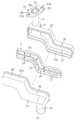
図3及び図4は、本発明の実施形態2に係るオイルストレーナ1を示すものであり、この実施形態2のオイルストレーナ1は、ケース3を上下方向だけでなく、幅方向にも屈曲させている点で実施形態1のものとは異なっており、他の部分は同じであるため、以下、実施形態1と同じ部分の説明は省略し、異なる部分について詳細に説明する。<<
3 and 4 show an
実施形態2のケース3の屈曲部13は、上下方向と該ケース3の幅方向との両方に屈曲している。すなわち、屈曲部13は、ケース3のオイル流入口10側がオイル流出口11側よりも下方に位置するように、かつ、ケース3のオイル流入口10側がオイル流出口11側よりもケース3の幅方向一側に位置するように屈曲している。ケース3の分割面Xは、実施形態1と同様に上下方向に平坦に延びている。 The
図4に示すように、フィルタエレメント2の網目部2bは、上下方向から見たときに、ケース3の長手方向に延びる中心線を通るように形成されている。すなわち、網目部2bには、屈曲部13の形状に対応して、第1ケース構成部材20内へ向けて折り曲げられた折り曲げ部2eを有している。これにより、網目部2bが第1ケース構成部材20の開放部分から第2ケース構成部材30側へ突出しないようになっている。このようにすることで、フィルタエレメント2を第1ケース構成部材20に挿入した状態で熱板溶着する際に、フィルタエレメント2の網目部2bが熱板に接触し難くなり、網目部2bの熱変形を抑制することが可能になる。 As shown in FIG. 4, the
この実施形態2のオイルストレーナ1によっても、実施形態1のものと同様な作用効果を得ることができる。 Also by the
また、このオイルストレーナ1では、ケース3が幅方向に屈曲していることから、ケース3の内部空間も同様に幅方向に屈曲して延びている。この場合に、上述のようにフィルタエレメント2に折り曲げ部2eを形成してケース3の屈曲部13に対応させているので、網目部2bをケース3の中心線近傍に位置付けることができる。これにより、ケース3内において、フィルタエレメント2の網目部2bよりも上流側の空間と下流側の空間との大きさをバランスさせることができ、オイルの流れをスムーズにすることができる。 Moreover, in this
尚、実施形態1、2では、屈曲部12、13が1箇所である場合ついて説明したが、図5及び図6に示す変形例のように、上下方向及び幅方向に屈曲する屈曲部13を複数設けてもよい。また、ケース3には、ケース3を幅方向にのみ屈曲させる屈曲部を複数設けてもよいし、上下方向にのみ屈曲させる屈曲部を複数設けてもよい。また、ケース3には、ケース3を幅方向にのみ屈曲させる屈曲部と、上下方向にのみ屈曲させる屈曲部とを設けてもよい。 In the first and second embodiments, the case where the
また、上記実施形態1、2の屈曲部12、13は、ケース3を幅方向にのみ屈曲させる形状であってもよい。 Further, the
また、上記実施形態1、2では、第1ケース構成部材20にオイル流出口11を設け、第2ケース構成部材30にオイル流入口10を設けているが、これに限らず、第1ケース構成部材20にオイル流入口10を設け、第2ケース構成部材30にオイル流出口11を設けるようにしてもよい。 In the first and second embodiments, the
また、上記実施形態では、溶着部32aをフィルタエレメント2の枠部2aに溶着するようにしているが、これに限らず、枠部2aに溶着しないようにしてもよい。 Moreover, in the said embodiment, although the
また、上記オイルストレーナ1は、エンジンやオートマチックトランスミッション以外の各種動力機械に使用することもできる。 The
以上説明したように、本発明に係るオイルストレーナは、例えば、車両に搭載されるエンジンのオイルパンに配設することができる。 As described above, the oil strainer according to the present invention can be disposed, for example, in an oil pan of an engine mounted on a vehicle.
1 オイルストレーナ
2 フィルタエレメント
3 ケース
10 オイル流入口
11 オイル流出口
12 屈曲部
13 屈曲部
20 第1ケース構成部材
30 第2ケース構成部材DESCRIPTION OF
Claims (2)
Translated fromJapanese上記ケース(3)は、長く延びるように形成されるとともに、該ケース(3)の長手方向一側にオイル流入口(10)が配置され、該ケース(3)の長手方向他側にオイル流出口(11)が配置され、さらに、長手方向に延びる略鉛直な仮想平面の分割面(X)で分割されて互いに溶着される第1ケース構成部材(20)と第2ケース構成部材(30)とを有し、
上記第1ケース構成部材(20)における分割面(X)と対向する側壁部は、上記ケース(3)の長手方向について該分割面(X)との離間距離が短い部位と長い部位とができるように屈曲形成され、上記第2ケース構成部材(30)における分割面(X)と対向する側壁部は、上記ケース(3)の長手方向について該分割面(X)との離間距離が短い部位と長い部位とができるように屈曲形成され、
上記第1及び第2ケース構成部材(20)、(30)の側壁部の屈曲により、上記ケース(3)の長手方向中間部には、該ケース(3)の幅方向に屈曲する屈曲部(13)が設けられ、
上記第1ケース構成部材(20)には、上記オイル流入口(10)と上記オイル流出口(11)との一方が設けられ、
上記第2ケース構成部材(30)には、上記オイル流入口(10)と上記オイル流出口(11)との他方が設けられ、
上記フィルタエレメント(2)は、上記第1ケース構成部材(20)の開放部分を覆う板状をなすとともに該開放部分を覆うように上記ケース(3)内において該ケース内空間をオイル流入口(10)側とオイル流出口(11)側とに分けるように配置され、
上記フィルタエレメント(2)の長手方向中間部は、上記網目部(2b)が上記ケース(3)の長手方向に延びる中心線近傍を通るように、上記ケース(3)の屈曲部(13)に対応して折れ曲がっていることを特徴とするオイルストレーナ(1)。An oil strainer (1) comprising a filter element (2) having a mesh part (2b) for filtration, and a case (3) for housing the filter element (2),
The case (3) is formed to extend long, and an oil inlet (10) is arranged on one side in the longitudinal direction of the case (3), and an oil flow is placed on the other side in the longitudinal direction of the case (3). A first case constituent member (20) and a second case constituent member (30) which are arranged at the outlet (11) and are further welded to each other by being divided bya substantially vertical virtual plane dividing plane (X) extending in the longitudinal direction. And
The side wall portion facing the dividing surface (X) in the first case constituent member (20) can have a portion having a short distance and a long portion with respect to the dividing surface (X) in the longitudinal direction of the case (3). The side wall portion that is bent in this manner and faces the dividing surface (X) in the second case component (30) has a short separation distance from the dividing surface (X) in the longitudinal direction of the case (3). And bent so that a long part can be formed,
Due to the bending of the side wall portions of the first and second case constituent members (20) and (30), a bent portion (bending in the width direction of the case (3) is formed at the longitudinal intermediate portion of the case (3). 13 ) is provided,
The first case component (20) is provided with one of the oil inlet (10) and the oil outlet (11),
The second case component (30) is provided with the other of the oil inlet (10) and the oil outlet (11),
The filter element (2) has a plate shape that covers the open portion of the first case component (20), and the internal space in the case (3) covers the open portion so as to cover the open portion. 10) is arranged so as to be divided into the oil outlet (11) side,
The middle part in the longitudinal direction of the filter element (2) is the bent part (13 ) of the case (3) so that the mesh part (2b) passes through the vicinity of the center line extending in the longitudinal direction of the case (3 ). Oil strainer (1), which is bent corresponding to
ケース(3)の屈曲部(13)は、該ケース(3)の長手方向について一側が他側に比べて下に位置するように上下方向にも屈曲することを特徴とするオイルストレーナ(1)。In the oil strainer (1) according to claim 1,
The bent portion of the case (3) (13), the oil strainer, characterized inthat one side in the longitudinal direction of the case (3) isalso bentin the verticalDirectionto lie down in comparison with the other side ( 1).
Priority Applications (1)
| Application Number | Priority Date | Filing Date | Title |
|---|---|---|---|
| JP2007281851AJP4958733B2 (en) | 2007-10-30 | 2007-10-30 | Oil strainer |
Applications Claiming Priority (1)
| Application Number | Priority Date | Filing Date | Title |
|---|---|---|---|
| JP2007281851AJP4958733B2 (en) | 2007-10-30 | 2007-10-30 | Oil strainer |
Publications (2)
| Publication Number | Publication Date |
|---|---|
| JP2009108765A JP2009108765A (en) | 2009-05-21 |
| JP4958733B2true JP4958733B2 (en) | 2012-06-20 |
Family
ID=40777500
Family Applications (1)
| Application Number | Title | Priority Date | Filing Date |
|---|---|---|---|
| JP2007281851AExpired - Fee RelatedJP4958733B2 (en) | 2007-10-30 | 2007-10-30 | Oil strainer |
Country Status (1)
| Country | Link |
|---|---|
| JP (1) | JP4958733B2 (en) |
Families Citing this family (7)
| Publication number | Priority date | Publication date | Assignee | Title |
|---|---|---|---|---|
| JP5638306B2 (en)* | 2010-07-30 | 2014-12-10 | ダイキョーニシカワ株式会社 | Oil strainer |
| JP5704912B2 (en)* | 2010-12-17 | 2015-04-22 | ダイキョーニシカワ株式会社 | Resin cylinder |
| JP5808621B2 (en)* | 2011-09-06 | 2015-11-10 | マツダ株式会社 | Oil strainer structure |
| JP6033641B2 (en)* | 2012-10-31 | 2016-11-30 | ダイキョーニシカワ株式会社 | Oil strainer |
| JP6302338B2 (en) | 2014-04-18 | 2018-03-28 | ダイキョーニシカワ株式会社 | Oil strainer |
| JP5784807B2 (en)* | 2014-08-27 | 2015-09-24 | ダイキョーニシカワ株式会社 | Resin cylinder |
| JP2017180336A (en)* | 2016-03-30 | 2017-10-05 | ダイハツ工業株式会社 | Oil strainer of internal combustion engine for automobile |
Family Cites Families (1)
| Publication number | Priority date | Publication date | Assignee | Title |
|---|---|---|---|---|
| JP4054745B2 (en)* | 2003-10-10 | 2008-03-05 | ダイキョーニシカワ株式会社 | strainer |
- 2007
- 2007-10-30JPJP2007281851Apatent/JP4958733B2/ennot_activeExpired - Fee Related
Also Published As
| Publication number | Publication date |
|---|---|
| JP2009108765A (en) | 2009-05-21 |
Similar Documents
| Publication | Publication Date | Title |
|---|---|---|
| JP4958733B2 (en) | Oil strainer | |
| EP2950907B1 (en) | Filter with dual pleat pack | |
| CN101784761B (en) | Oil pan | |
| US7857143B2 (en) | Suction filter and fuel supply device | |
| JP6302338B2 (en) | Oil strainer | |
| US20070245700A1 (en) | Air filtering device | |
| US10086318B2 (en) | Filter with internal frame openings | |
| JP5935681B2 (en) | Air cleaner | |
| EP2950908B1 (en) | Filter with dual pleat pack | |
| JP4506634B2 (en) | Filter and cleaner | |
| JP4867588B2 (en) | Oil filter for automatic transmission | |
| JP6602680B2 (en) | Oil strainer | |
| JP6778299B2 (en) | Oil strainer | |
| JP2014139423A (en) | Baffle plate structure | |
| JP5046805B2 (en) | Oil strainer | |
| JP6033641B2 (en) | Oil strainer | |
| JP5349843B2 (en) | strainer | |
| JP2006322408A (en) | Oil strainer for internal combustion engine | |
| CN216342517U (en) | Built-in filter | |
| JP2009036054A (en) | Oil strainer | |
| JP2008162526A (en) | Oil tank | |
| JP2016114026A (en) | Oil strainer | |
| JP2014125989A (en) | Filter and oil strainer | |
| JP2006132769A (en) | Fluid filter device for vehicle |
Legal Events
| Date | Code | Title | Description |
|---|---|---|---|
| A621 | Written request for application examination | Free format text:JAPANESE INTERMEDIATE CODE: A621 Effective date:20100805 | |
| A977 | Report on retrieval | Free format text:JAPANESE INTERMEDIATE CODE: A971007 Effective date:20110728 | |
| A131 | Notification of reasons for refusal | Free format text:JAPANESE INTERMEDIATE CODE: A131 Effective date:20110802 | |
| A521 | Request for written amendment filed | Free format text:JAPANESE INTERMEDIATE CODE: A523 Effective date:20111003 | |
| A131 | Notification of reasons for refusal | Free format text:JAPANESE INTERMEDIATE CODE: A131 Effective date:20111115 | |
| A521 | Request for written amendment filed | Free format text:JAPANESE INTERMEDIATE CODE: A523 Effective date:20111222 | |
| TRDD | Decision of grant or rejection written | ||
| A01 | Written decision to grant a patent or to grant a registration (utility model) | Free format text:JAPANESE INTERMEDIATE CODE: A01 Effective date:20120221 | |
| A01 | Written decision to grant a patent or to grant a registration (utility model) | Free format text:JAPANESE INTERMEDIATE CODE: A01 | |
| A61 | First payment of annual fees (during grant procedure) | Free format text:JAPANESE INTERMEDIATE CODE: A61 Effective date:20120319 | |
| FPAY | Renewal fee payment (event date is renewal date of database) | Free format text:PAYMENT UNTIL: 20150330 Year of fee payment:3 | |
| R150 | Certificate of patent or registration of utility model | Ref document number:4958733 Country of ref document:JP Free format text:JAPANESE INTERMEDIATE CODE: R150 Free format text:JAPANESE INTERMEDIATE CODE: R150 | |
| R250 | Receipt of annual fees | Free format text:JAPANESE INTERMEDIATE CODE: R250 | |
| R250 | Receipt of annual fees | Free format text:JAPANESE INTERMEDIATE CODE: R250 | |
| R250 | Receipt of annual fees | Free format text:JAPANESE INTERMEDIATE CODE: R250 | |
| R250 | Receipt of annual fees | Free format text:JAPANESE INTERMEDIATE CODE: R250 | |
| R250 | Receipt of annual fees | Free format text:JAPANESE INTERMEDIATE CODE: R250 | |
| R250 | Receipt of annual fees | Free format text:JAPANESE INTERMEDIATE CODE: R250 | |
| R250 | Receipt of annual fees | Free format text:JAPANESE INTERMEDIATE CODE: R250 | |
| R250 | Receipt of annual fees | Free format text:JAPANESE INTERMEDIATE CODE: R250 | |
| R250 | Receipt of annual fees | Free format text:JAPANESE INTERMEDIATE CODE: R250 | |
| LAPS | Cancellation because of no payment of annual fees |