JP4955296B2 - Graphical user interface including pop-up window for ophthalmic surgical systems - Google Patents
Graphical user interface including pop-up window for ophthalmic surgical systemsDownload PDFInfo
- Publication number
- JP4955296B2 JP4955296B2JP2006112081AJP2006112081AJP4955296B2JP 4955296 B2JP4955296 B2JP 4955296B2JP 2006112081 AJP2006112081 AJP 2006112081AJP 2006112081 AJP2006112081 AJP 2006112081AJP 4955296 B2JP4955296 B2JP 4955296B2
- Authority
- JP
- Japan
- Prior art keywords
- time
- window
- user interface
- parameter
- value
- Prior art date
- Legal status (The legal status is an assumption and is not a legal conclusion. Google has not performed a legal analysis and makes no representation as to the accuracy of the status listed.)
- Active
Links
- 230000004044responseEffects0.000claimsdescription29
- 230000002207retinal effectEffects0.000claimsdescription10
- 230000007423decreaseEffects0.000abstractdescription51
- 230000008859changeEffects0.000abstractdescription17
- 238000009795derivationMethods0.000abstract1
- 230000014509gene expressionEffects0.000description20
- 230000000994depressogenic effectEffects0.000description12
- 238000006073displacement reactionMethods0.000description11
- 238000000034methodMethods0.000description6
- 238000001356surgical procedureMethods0.000description6
- 238000002604ultrasonographyMethods0.000description6
- 238000005345coagulationMethods0.000description5
- 230000015271coagulationEffects0.000description5
- 230000003247decreasing effectEffects0.000description5
- 230000000737periodic effectEffects0.000description5
- 238000012886linear functionMethods0.000description4
- 230000006872improvementEffects0.000description3
- 239000003550markerSubstances0.000description3
- 230000035945sensitivityEffects0.000description3
- 230000000881depressing effectEffects0.000description2
- 238000004945emulsificationMethods0.000description2
- 235000019589hardnessNutrition0.000description2
- 230000007246mechanismEffects0.000description2
- 230000003542behavioural effectEffects0.000description1
- 230000009286beneficial effectEffects0.000description1
- 238000004140cleaningMethods0.000description1
- 239000013078crystalSubstances0.000description1
- 239000011521glassSubstances0.000description1
- 230000002262irrigationEffects0.000description1
- 238000003973irrigationMethods0.000description1
- 238000013507mappingMethods0.000description1
- 201000004673mature cataractDiseases0.000description1
- 238000012986modificationMethods0.000description1
- 230000004048modificationEffects0.000description1
- 230000002250progressing effectEffects0.000description1
- 210000001525retinaAnatomy0.000description1
- 239000000523sampleSubstances0.000description1
- 238000000926separation methodMethods0.000description1
- 238000006467substitution reactionMethods0.000description1
- 230000000007visual effectEffects0.000description1
Images


Classifications
- A—HUMAN NECESSITIES
- A61—MEDICAL OR VETERINARY SCIENCE; HYGIENE
- A61F—FILTERS IMPLANTABLE INTO BLOOD VESSELS; PROSTHESES; DEVICES PROVIDING PATENCY TO, OR PREVENTING COLLAPSING OF, TUBULAR STRUCTURES OF THE BODY, e.g. STENTS; ORTHOPAEDIC, NURSING OR CONTRACEPTIVE DEVICES; FOMENTATION; TREATMENT OR PROTECTION OF EYES OR EARS; BANDAGES, DRESSINGS OR ABSORBENT PADS; FIRST-AID KITS
- A61F9/00—Methods or devices for treatment of the eyes; Devices for putting in contact-lenses; Devices to correct squinting; Apparatus to guide the blind; Protective devices for the eyes, carried on the body or in the hand
- A61F9/007—Methods or devices for eye surgery
- A61F9/00736—Instruments for removal of intra-ocular material or intra-ocular injection, e.g. cataract instruments
- A61F9/00745—Instruments for removal of intra-ocular material or intra-ocular injection, e.g. cataract instruments using mechanical vibrations, e.g. ultrasonic
- G—PHYSICS
- G16—INFORMATION AND COMMUNICATION TECHNOLOGY [ICT] SPECIALLY ADAPTED FOR SPECIFIC APPLICATION FIELDS
- G16H—HEALTHCARE INFORMATICS, i.e. INFORMATION AND COMMUNICATION TECHNOLOGY [ICT] SPECIALLY ADAPTED FOR THE HANDLING OR PROCESSING OF MEDICAL OR HEALTHCARE DATA
- G16H40/00—ICT specially adapted for the management or administration of healthcare resources or facilities; ICT specially adapted for the management or operation of medical equipment or devices
- G16H40/60—ICT specially adapted for the management or administration of healthcare resources or facilities; ICT specially adapted for the management or operation of medical equipment or devices for the operation of medical equipment or devices
- G16H40/63—ICT specially adapted for the management or administration of healthcare resources or facilities; ICT specially adapted for the management or operation of medical equipment or devices for the operation of medical equipment or devices for local operation
- A—HUMAN NECESSITIES
- A61—MEDICAL OR VETERINARY SCIENCE; HYGIENE
- A61B—DIAGNOSIS; SURGERY; IDENTIFICATION
- A61B17/00—Surgical instruments, devices or methods
- A61B2017/00017—Electrical control of surgical instruments
- A61B2017/00199—Electrical control of surgical instruments with a console, e.g. a control panel with a display
- A—HUMAN NECESSITIES
- A61—MEDICAL OR VETERINARY SCIENCE; HYGIENE
- A61B—DIAGNOSIS; SURGERY; IDENTIFICATION
- A61B17/00—Surgical instruments, devices or methods
- A61B2017/00973—Surgical instruments, devices or methods pedal-operated
- A61B2017/00977—Surgical instruments, devices or methods pedal-operated the depression depth determining the power rate
- A—HUMAN NECESSITIES
- A61—MEDICAL OR VETERINARY SCIENCE; HYGIENE
- A61B—DIAGNOSIS; SURGERY; IDENTIFICATION
- A61B34/00—Computer-aided surgery; Manipulators or robots specially adapted for use in surgery
- A61B34/25—User interfaces for surgical systems
- Y—GENERAL TAGGING OF NEW TECHNOLOGICAL DEVELOPMENTS; GENERAL TAGGING OF CROSS-SECTIONAL TECHNOLOGIES SPANNING OVER SEVERAL SECTIONS OF THE IPC; TECHNICAL SUBJECTS COVERED BY FORMER USPC CROSS-REFERENCE ART COLLECTIONS [XRACs] AND DIGESTS
- Y10—TECHNICAL SUBJECTS COVERED BY FORMER USPC
- Y10S—TECHNICAL SUBJECTS COVERED BY FORMER USPC CROSS-REFERENCE ART COLLECTIONS [XRACs] AND DIGESTS
- Y10S715/00—Data processing: presentation processing of document, operator interface processing, and screen saver display processing
- Y10S715/973—Scroll tool, e.g. window scroll bar
Landscapes
- Health & Medical Sciences (AREA)
- Engineering & Computer Science (AREA)
- Biomedical Technology (AREA)
- General Health & Medical Sciences (AREA)
- Public Health (AREA)
- Ophthalmology & Optometry (AREA)
- Surgery (AREA)
- Life Sciences & Earth Sciences (AREA)
- Veterinary Medicine (AREA)
- Animal Behavior & Ethology (AREA)
- Heart & Thoracic Surgery (AREA)
- Nuclear Medicine, Radiotherapy & Molecular Imaging (AREA)
- Medical Informatics (AREA)
- Vascular Medicine (AREA)
- Primary Health Care (AREA)
- Business, Economics & Management (AREA)
- General Business, Economics & Management (AREA)
- Epidemiology (AREA)
- Human Computer Interaction (AREA)
- Robotics (AREA)
- Molecular Biology (AREA)
- Ultra Sonic Daignosis Equipment (AREA)
- Surgical Instruments (AREA)
- User Interface Of Digital Computer (AREA)
- Measuring And Recording Apparatus For Diagnosis (AREA)
- Measurement And Recording Of Electrical Phenomena And Electrical Characteristics Of The Living Body (AREA)
- Electrotherapy Devices (AREA)
- Eye Examination Apparatus (AREA)
- Measuring Pulse, Heart Rate, Blood Pressure Or Blood Flow (AREA)
- Magnetic Resonance Imaging Apparatus (AREA)
Abstract
Description
Translated fromJapanese 本願は、その優先権がU.S.C.セクション119の35に基づく、2005年6月30日に出願された、同時係属米国出願第11/170,952の一部継続(CIP)出願であり、参照によりその全体の内容をここに引用したものとする。本願はまた、U.S.C.セクション119の35に基づき、2005年4月15日に出願された米国仮特許出願第60/671,879号への優先権を主張するものであり、参照によりその全体の内容をここに引用したものとする。 In the present application, the priority is U.S. Pat. S. C. A continuation-in-part (CIP) application of copending US application 11 / 170,952, filed June 30, 2005, based on
本発明は、一般的に外科用システムのためのグラフィカルユーザーインタフェースに関し、より特別には、システムのパラメータを調整するための、分離したポップアップまたはダイアログウィンドウを含む、水晶体超音波乳化吸引および硝子体網膜外科用システムのような、眼外科用システムのためのグラフィカルユーザーインタフェースに関する。 The present invention relates generally to graphical user interfaces for surgical systems, and more particularly to phacoemulsification and vitreous retina, including a separate pop-up or dialog window for adjusting system parameters. It relates to a graphical user interface for an ophthalmic surgical system, such as a surgical system.
最新の眼外科用システム、さらに特に、例えば、最新の眼科および硝子体網膜外科用システムは、外科用システムに接続され、フットペダルを用いることにより外科医により制御される外科用装置または器具の複数のパラメータをモニタして、表示するように設計されている。このようなシステムは、特に外科的処置の間、外科医により表示され、制御されなければならない複数のパラメータがあるために複雑であり得る。 State-of-the-art ophthalmic surgical systems, and more particularly, for example, state-of-the-art ophthalmic and vitreous retinal surgical systems, are connected to a surgical system and include a plurality of surgical devices or instruments that are controlled by a surgeon using a foot pedal Designed to monitor and display parameters. Such a system can be complex due to the multiple parameters that must be displayed and controlled by the surgeon, especially during surgical procedures.
ある周知の眼外科用システムは、固定レベルでの超音波エネルギーの適用を可能にする。例えば、水晶体超音波乳化吸引外科用システムにおいては、フットペダルは、特定のパワーレベルにある超音波エネルギーを起動および停止するためのオン/オフスイッチとして働く。フットペダルが押されると、装置は作動し、パワーレベルは一定であり、中断がない、つまり「連続」である。連続パワーは、ハンドピースにおいて、圧電結晶に加えられる電圧量にほぼ比例する。 One well-known ophthalmic surgical system allows the application of ultrasonic energy at a fixed level. For example, in a phacoemulsification aspiration surgical system, the foot pedal acts as an on / off switch to activate and deactivate ultrasound energy at a specific power level. When the foot pedal is pressed, the device operates, the power level is constant and there is no interruption, ie “continuous”. The continuous power is approximately proportional to the amount of voltage applied to the piezoelectric crystal in the handpiece.
「連続」パワーシステムは外科医が種々の方法でパワーを制御できる「直線」モードの導入により改良された。パワーがフットペダルの変位と比例しまたは直線的となるように、外科医はフットペダル位置に基づいてパワーを制御する。このように、外科医がフットペダルを押すにつれて、より多くのパワーが供給され、そして、フットペダルがリリースされるにつれて、より少ないパワーが供給される。更なる改良は、「パルス」モードの導入に関連していた。「パルス」モードにおいて、エネルギーは、一定のデューティサイクルで周期的なパルスで供給される。外科医はフットペダルを押すかまたはリリースすることによって、パワーの量を増減し、それにより、固定幅のパルスの振幅を増減する。更なる強化は、「バースト」モードの導入に関連していた。「バースト」モードにおいて、パワーは、一連の周期的、固定幅、および一定振幅のパルスにより供給される。各パルスの後に、「オフ」タイムが続く。オフ・タイムは、フットペダルを押し、リリースすることによって、外科医により変更される。 The “continuous” power system has been improved with the introduction of a “linear” mode that allows the surgeon to control the power in various ways. The surgeon controls the power based on the foot pedal position so that the power is proportional or linear with the displacement of the foot pedal. In this way, more power is delivered as the surgeon presses the foot pedal, and less power is delivered as the foot pedal is released. Further improvements were associated with the introduction of the “pulse” mode. In “pulse” mode, energy is supplied in periodic pulses with a constant duty cycle. The surgeon increases or decreases the amount of power by pressing or releasing the foot pedal, thereby increasing or decreasing the amplitude of the fixed width pulse. Further enhancements were related to the introduction of “burst” mode. In “burst” mode, power is supplied by a series of periodic, fixed width, constant amplitude pulses. Each pulse is followed by an “off” time. The off time is changed by the surgeon by pressing and releasing the foot pedal.
連続、「直線」、「パルス」、そして、「バースト」モード、およびそれらの作動パラメータを収容するために、水晶体超音波乳化吸引システムの周知のユーザーインタフェースは、一般的にいくつかの、表示画面上の特定位置を占有する、人間の操作可能なコントローラおよび領域または要素を含む。周知のユーザーインタフェースには、外科用システムの動作特性の所望の数値を設定するためのボタン、矢印、スイッチ、バーおよび/またはツマミが含まれる。フットペダル位置に関係なく、特定のパラメータは固定されるかまたは一定値を有するものもあるが、他のパラメータは、フットペダルによって、例えば、直線的に変化する。インタフェースは、結果として生成されるモードまたはパルスのタイプを制御する制御信号を、外科用器具に供給するために外科医により操作される。 In order to accommodate continuous, “straight”, “pulse” and “burst” modes, and their operating parameters, the well-known user interface of the phacoemulsification system generally has several display screens Includes human-operable controllers and areas or elements that occupy specific locations above. Known user interfaces include buttons, arrows, switches, bars and / or knobs for setting desired numerical values for the operating characteristics of the surgical system. Regardless of the foot pedal position, certain parameters may be fixed or have a constant value, while other parameters vary, for example, linearly with the foot pedal. The interface is manipulated by the surgeon to provide the surgical instrument with control signals that control the resulting mode or type of pulse.
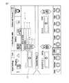
図1および図2は、水晶体超音波乳化吸引システムのための一つの周知のインタフェースを例示する。外科医は、手動でパワーモードを選択バーまたはメニュー10から選択する。このインタフェースにおいて、メニュー10は、「超音波連続」、「超音波パルス」、および「超音波バースト」メニューバー12、14、および16をそれぞれ含む。図1および図2において示される例において、連続パワーメニューバー12が、メニュー10から選択される。パワー限界は、フィールド20において示される。連続パワーまたはパワー限界の最大値は、上下矢印24を使用して調整される。この例では、連続パワー限界は、最大許容パワーの「35」即ち35%であるように選択される。パワー限界フィールド20のバックグラウンドの直線26で示すように、連続パワーは、最大値の35%まで直線的に変化する。現在のパワーレベルは、フィールド28に示される。示された例では、フットペダルがリリースされているときの現在のパワーを画面が示しているので、現在のパワーは、この例では、「0」即ち0%である。フットペダルを押すことにより、エネルギーは0%から35%まで直線的に増加する。外科医が「連続」モードから他のモードに変更したいときには、外科医は「超音波連続」バー12を選択して、利用できるパルスモードのメニュー10が表示されるようにする。これにより、外科医はメニュー10から他のモードを選択できる。1 and 2 illustrate one known interface for a phacoemulsification system. The surgeon manually selects the power mode from the selection bar or
周期的超音波パルスの適用は、パワー、パルスの持続時間、「オン」またはアクティブタイム、および「オフ」タイムの持続時間またはパルス間の持続時間に基づいて記述される。または、パルスは、パルスレートおよびデューティサイクルを使用して指定できる。パルスレートは単位時間に含まれるパルス数である。デューティサイクルは、超音波がアクティブなときの超音波周期の一部分である。つまり、デューティサイクルはオン/(オン+オフ)の比である。 The application of periodic ultrasonic pulses is described based on power, pulse duration, “on” or active time, and “off” time duration or duration between pulses. Alternatively, pulses can be specified using pulse rate and duty cycle. The pulse rate is the number of pulses included in a unit time. The duty cycle is a portion of the ultrasound cycle when the ultrasound is active. That is, the duty cycle is the ratio of on / (on + off).
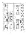
図3は、「超音波パルス」メニューバー14がメニュー10から選択されていることを示す。外科医は手動で35%の最大パワーレベルを選択し、そしてそれは、フットペダルが押されて、リリースされるにつれて直線的に変化する。更に、インタフェースは、パルスレートまたは1秒当りのパルス数(pps)のためのフィールド30および「オン・タイム」(タイムオンの百分率)のためのフィールド40を含む。しかし、1秒当りのパルス数(pps)およびオン・タイムは、フットペダルの動きによって変化しない。むしろ、ppsは矢印34を使用して14ppsで固定され、そして、オン・タイムは矢印44を使用して45%で固定されている。このように、ppsおよびオン・タイム値は、フットペダルが変位しても変化せず、矢印34および44を使用して外科医が手動で調整しなければならない。フットペダルが押されるにつれて、パワーは0から35%に直線的に増加して、1秒当り14パルスの固定レートで、45%固定のデューティサイクルにて供給される。 FIG. 3 shows that the “ultrasonic pulse”
図2および図4を参照すると、「超音波バースト」モードがメニュー10から選択されると、同じ限界およびパワーフィールド28と、限界フィールド20が設けられる。上記のように、パワーはフットペダルによって直線的に変化する。ppsおよびオン・タイムのフィールド30および40(図3に示すように)ではなくて、インタフェースは「バースト」モードにおいては、オン・タイムまたはオン(ミリ秒)のためのフィールド50およびオフ・タイムまたはオフ(ミリ秒)のためのフィールド60を表示する。オン(ミリ秒)値は固定されており、フットペダルが移動しても変化しない。オン・タイム(ミリ秒)は70msに固定して示され、矢印54を使用して調整できる。オフ・タイムは、フットペダルの変位により、ある値からゼロに減少する。この「バースト」モードにおいて、フットペダルが「オフ・タイム」を変更することによって押し下げられるにつれて、パワーは0から40%に増加し、各パルスの持続時間はフットペダルの変位を通して一定の70msのままである。 With reference to FIGS. 2 and 4, when the “ultrasonic burst” mode is selected from the
周知のインタフェースが過去において、水晶体超音波乳化吸引および硝子体網膜外科処置を実行するために首尾よく用いられたが、それらはまだ改良の余地がある。特に、外科医が、実行される特別な処置および遭遇する外科的条件に依存して、異なる外科的特性とパルスモードを選択かつ制御することができるように、インタフェースの視覚的および機能的な態様を強化できる。ユーザーインタフェースは、異なるモードおよびそれらのパラメータが迅速かつ容易に調整することを可能にする追加的な制御可能な表示要素を含むべきである。これらの改良は、過度にユーザーインタフェースおよびそれが機能する方法を複雑にせずになされなければならない。更に、インタフェースは連続、直線的、パルス、バースト、そして、周知のモードの組合せおよび変形であり得る新しいモードを含む、種々の超音波駆動モードの種々の作動パラメータを効果的に示すことができなければならない。理解可能な方法で、パルスパラメータを迅速に調整できるということはまた、装置のセットアップを簡素化し、操作コストを削減し、安全性を高める。 Although well-known interfaces have been used successfully in the past to perform phacoemulsification and vitreous retinal surgery, they still have room for improvement. In particular, the visual and functional aspects of the interface allow the surgeon to select and control different surgical characteristics and pulse modes depending on the particular procedure being performed and the surgical conditions encountered. Can be strengthened. The user interface should include additional controllable display elements that allow different modes and their parameters to be adjusted quickly and easily. These improvements must be made without unduly complicating the user interface and the way it functions. In addition, the interface must be able to effectively show different operating parameters of different ultrasonic drive modes, including new modes that can be continuous, linear, pulsed, burst, and combinations and variations of known modes. I must. The ability to quickly adjust the pulse parameters in an understandable manner also simplifies device setup, reduces operating costs and increases safety.
本発明の一つの実施形態によれば、コントローラに応答して調整されるパルスを生成する、水晶体超音波乳化吸引および硝子体網膜外科用システムのような眼外科用システムのためのユーザーインタフェースは、表示画面上に表示される表示要素とウィンドウを含む。表示要素は、コントローラの位置に関して、眼外科用システムにより生成されるパルスのパラメータの表現を含む。ウィンドウは、表示画面にタッチすることに応答して、表示画面上に生成され、表示される。ウィンドウは、コントローラの位置に関するパルスのパラメータの表現を含む表示要素を含む。 According to one embodiment of the present invention, a user interface for an ophthalmic surgical system, such as a phacoemulsification and vitreous retinal surgical system, that generates a pulse that is adjusted in response to a controller, Includes display elements and windows that are displayed on the display screen. The display element includes a representation of the parameters of the pulses generated by the ophthalmic system with respect to the position of the controller. A window is generated and displayed on the display screen in response to touching the display screen. The window includes a display element that includes a representation of the parameters of the pulse with respect to the position of the controller.
本発明の別の実施形態によれば、水晶体超音波乳化吸引および硝子体網膜外科用システムのような眼外科用システムのためのユーザーインタフェースは、表示画面上に表示される表示要素とウィンドウを含む。表示要素は、コントローラの位置に関して、眼外科用システムにより生成されるパルスのパラメータの表現を含む。ウィンドウは、表示画面にタッチすることに応答して生成される。ウィンドウは、コントローラの位置に関するパルスのパラメータの表現を含む表示要素と、ウィンドウの表示要素に表現されるパラメータの値を変更するための調整要素を含む。ウィンドウに表示されるパラメータの現在の表現は、ウィンドウにおいて表示画面にタッチすることに応答して異なる表現に変更される。パラメータの値は、調整要素において表示画面にタッチすることにより変更される。ユーザーがパラメータを調整した後、ウィンドウは、ウィンドウの予め決められた領域において、表示画面にタッチすることにより閉じることができる。 According to another embodiment of the present invention, a user interface for an ophthalmic surgical system, such as a phacoemulsification and vitreous retinal surgical system, includes a display element and a window displayed on a display screen. . The display element includes a representation of the parameters of the pulses generated by the ophthalmic system with respect to the position of the controller. The window is generated in response to touching the display screen. The window includes a display element that includes a representation of the pulse parameters relating to the position of the controller and an adjustment element for changing the value of the parameter represented in the display element of the window. The current representation of the parameter displayed in the window is changed to a different representation in response to touching the display screen in the window. The value of the parameter is changed by touching the display screen in the adjustment element. After the user adjusts the parameters, the window can be closed by touching the display screen in a predetermined area of the window.
本発明の他の別の実施形態によれば、水晶体超音波乳化吸引および硝子体網膜外科用システムのような眼外科用システムのためのユーザーインタフェースは、表示画面上に表示される表示要素とウィンドウを含む。表示要素は、フットペダルの位置に関するパルスのパラメータの表現を含む。ウィンドウは、システムの表示画面にタッチすることに応答して生成される。ウィンドウは、コントローラの位置に関するパルスのパラメータの表現を含む表示要素と、表示要素に表現されるパラメータの値を変更するための調整要素を含む。パラメータの少なくとも三つの表現が、ウィンドウの表示要素において表示画面にタッチすることにより、ウィンドウの表示要素に順に表示される。これにより、ユーザーは表現をスクロールできる。ウィンドウの表示要素において表示される表現は、パラメータの選択された表現である。パラメータの値は、調整要素において表示画面にタッチすることにより変更される。パラメータの調整後、ウィンドウは、ウィンドウの予め決められた領域において表示画面にタッチすることにより閉じることができる。 According to another alternative embodiment of the present invention, a user interface for an ophthalmic surgical system, such as phacoemulsification and vitreous retinal surgical system, includes display elements and windows displayed on the display screen. including. The display element includes a representation of the parameters of the pulse relating to the position of the foot pedal. The window is generated in response to touching the system display screen. The window includes a display element that includes a representation of the pulse parameters relating to the position of the controller and an adjustment element for changing the value of the parameter represented in the display element. At least three representations of the parameters are sequentially displayed on the display elements of the window by touching the display screen on the display elements of the window. This allows the user to scroll through the representation. The representation displayed in the display element of the window is the selected representation of the parameter. The value of the parameter is changed by touching the display screen in the adjustment element. After adjusting the parameters, the window can be closed by touching the display screen in a predetermined area of the window.
本発明の他の別の実施形態によれば、コントローラに応答して、眼外科用システムの表示画面上に表示される設定に基づいて調整されるパルスを生成する、水晶体超音波乳化吸引および硝子体網膜外科用システムのような眼外科用システムのためのユーザーインタフェースは、第1表示要素とウィンドウを含む。第1表示要素は表示画面上に示され、眼外科用システムにより生成されるパルスのパラメータの値を含む。ウィンドウは表示画面上に表示され、表示画面にタッチすることに応答して生成される。ウィンドウは、第2表示要素を含む。第2表示要素は、眼外科用システムにより生成されるパルスのパラメータの値を含む。 According to another alternative embodiment of the present invention, phacoemulsification and glass in response to a controller that generates pulses that are adjusted based on settings displayed on the display screen of the ophthalmic surgical system. A user interface for an ophthalmic surgical system, such as a body retinal surgical system, includes a first display element and a window. The first display element is shown on the display screen and includes the values of the parameters of the pulse generated by the ophthalmic surgical system. The window is displayed on the display screen and is generated in response to touching the display screen. The window includes a second display element. The second display element includes the value of the parameter of the pulse generated by the ophthalmic surgical system.
本発明の更に別の実施形態によれば、コントローラに応答して、眼外科用システムの表示画面上に表示される設定に基づいて調整されるパルスを生成する眼外科用システムのためのユーザーインタフェースは、第1表示要素とウィンドウを含む。第1表示要素は表示画面上に示され、眼外科用システムにより生成されるパルスのパラメータの値を含む。ウィンドウは表示画面上に表示され、第1表示要素において表示画面にタッチすることに応答して生成される。ウィンドウは、眼外科用システムにより生成されるパルスのパラメータの値を含む第2表示要素と、パラメータの値を変更するための調整要素を含む。 According to yet another embodiment of the present invention, a user interface for an ophthalmic surgical system that generates pulses that are adjusted based on settings displayed on a display screen of the ophthalmic surgical system in response to a controller. Includes a first display element and a window. The first display element is shown on the display screen and includes the values of the parameters of the pulse generated by the ophthalmic surgical system. The window is displayed on the display screen and is generated in response to touching the display screen at the first display element. The window includes a second display element that includes the value of the parameter of the pulse generated by the ophthalmic surgical system and an adjustment element for changing the value of the parameter.
種々の実施形態において、ウィンドウに表示されるパラメータの現在の表現は、例えば、ウィンドウの表示要素のような、ウィンドウにおいて表示画面にタッチすることに応答して異なる表現に変更される。ウィンドウは、初期表示要素において表示画面にタッチすることにより生成される。パラメータの調整に使用される調整要素は、一つまたは二つ以上の矢印とスライドバーであってよい。表示画面の予め定義された領域は、ウィンドウを閉じるためにタッチすることができる。予め定義された領域は、例えば、アイコンまたはボタンで定義された、ウィンドウ内の予め定義された領域であってよい。ウィンドウに表現されるパラメータは、例えば、パワー、パルスオン・タイム、およびパルスオフ・タイムのような非超音波および超音波パラメータであってよい。初期表示画面およびウィンドウの表示要素のパラメータは、増加、減少、一定、直線的、および指数または多項式のような非直線的なものであってよい。 In various embodiments, the current representation of the parameter displayed in the window is changed to a different representation in response to touching the display screen in the window, eg, the display element of the window. The window is generated by touching the display screen in the initial display element. The adjustment elements used to adjust the parameters may be one or more arrows and a slide bar. A predefined area of the display screen can be touched to close the window. The predefined area may be, for example, a predefined area within a window defined by an icon or button. The parameters represented in the window may be non-ultrasonic and ultrasonic parameters such as power, pulse on time, and pulse off time, for example. Initial display screen and window display element parameters may be increasing, decreasing, constant, linear, and non-linear, such as exponential or polynomial.
更に、種々の実施形態において、ウィンドウは、第1表示要素において表示画面にタッチすることに応答して生成できる。ウィンドウは、例えば、一つの調整要素または一対の調整要素のような種々の調整要素を含むことができる。調整要素は、矢印またはスライドバーであってよい。更にウィンドウは、眼科システムの特別な機能を操作可能にするかどうかを選択するための、「イネーブル」および「ディスエーブル」ボタンのようなイネーブル要素を含むことができる。ポップアップまたはダイアログウィンドウもまた、アクティブでない時間が予め決められた時間だけ経過すると削除または徐々に消えていくようにすることができる。また、ユーザーは、「終了」ボタンのような、ウィンドウのボタンまたは要素を押すことによりウィンドウを閉じることができる。更に、パラメータの値は、利用可能な値のメニューから選択できる。 Further, in various embodiments, the window can be generated in response to touching the display screen at the first display element. The window can include various adjustment elements such as, for example, a single adjustment element or a pair of adjustment elements. The adjustment element may be an arrow or a slide bar. In addition, the window can include enable elements such as “Enable” and “Disable” buttons for selecting whether to enable special functions of the ophthalmic system. Pop-ups or dialog windows can also be deleted or gradually disappear after a predetermined period of inactivity. The user can also close the window by pressing a button or element of the window, such as an “Exit” button. In addition, the value of the parameter can be selected from a menu of available values.
以下の説明では、説明の一部を形成し、本発明を実施することができる特定の実施形態を示す添付図面を参照する。変更が発明の範囲から逸脱することなくなされ得ることが理解されよう。 In the following description, reference is made to the accompanying drawings that form a part hereof, and in which is shown by way of illustration specific embodiments in which the invention may be practiced. It will be understood that changes may be made without departing from the scope of the invention.
本発明の実施形態は、水晶体超音波乳化吸引外科用システムのような眼外科用システムよって生成される超音波駆動またはパルスモードに対する改良された制御、および異なるパルスモードのパラメータに対する改良された制御を提供するグラフィカルユーザーインタフェースを目的とする。実施形態は、外科医により迅速かつ容易に選択および調整できて異なるモードを選択し、種々のモードをカスタマイズするために、種々のパルスパラメータを調整可能にする表示要素を提供する。選択できるパルスモードには、「連続」、「パルス」、およぴ「バースト」モードが含まれ、更に、以前は水晶体超音波乳化吸引システムでは容易に利用できなかったハイブリッドまたは組合せモードが含まれる。パラメータ、特性、およびパルスの機能の表現は、表示要素に表示される。表現は、パルス特性、例えばオン・タイムおよびオフ・タイムのような表現をユーザーが選択できるメニューを生成するために、特定の表示要素において表示画面にタッチすることにより変更することができる。あるいは、ユーザーは、パルスのオン・タイムおよびオフ・タイムの特性または機能の異なる表現をスクロールすることができる。選択される表現は、フットペダルのようなコントローラの変位に応じて、オン・タイムおよびオフ・タイムがどのように変化するか、および水晶体超音波乳化吸引システムにより生成されるパルスのタイプおよび特性のようなパルス特性の機能または挙動を示す。分離ウィンドウは、表現および/または値を調整するために、表示画面にタッチすることに応答して生成できる。 Embodiments of the present invention provide improved control over ultrasonic drive or pulse modes generated by an ophthalmic surgical system, such as a phacoemulsification suction surgical system, and improved control over different pulse mode parameters. The purpose is to provide a graphical user interface. Embodiments provide a display element that can be quickly and easily selected and adjusted by the surgeon to select different modes and to adjust various pulse parameters to customize the various modes. Selectable pulse modes include “continuous”, “pulse”, and “burst” modes, as well as hybrid or combination modes that were not previously readily available for phacoemulsification systems . A representation of parameters, characteristics, and pulse function is displayed on the display element. The representation can be changed by touching the display screen at a particular display element to generate a menu that allows the user to select representations such as pulse characteristics, eg, on time and off time. Alternatively, the user can scroll through different representations of pulse on-time and off-time characteristics or functions. The representation chosen is how the on-time and off-time vary depending on the displacement of the controller, such as a foot pedal, and the type and characteristics of the pulses produced by the phacoemulsification system. It shows the function or behavior of such pulse characteristics. The separation window can be generated in response to touching the display screen to adjust the representation and / or values.
本発明の実施形態は、フットペダルの変位に関して直線的に増加し、非直線的に増加し、直線的に減少し、非直線的に減少し、および実質的に一定に維持されるように、オン・タイム、オフ・タイム、および他のパルス表現を調整可能にすることにより、周知のインタフェースを改良する。これらの設置は、表現がオン・タイム、および/またはオフ・タイムが直線的に、または非直線的に減少するか増加するか、または一定に維持されるかどうかを決定する。異なるパルスモードは、オン・タイムおよびオフ・タイムが変化する(または、変化しない)方法を選択することによって生成できる。例えば、フットペダルの動きに応答して、オン・タイムおよびオフ・タイムが各々増加し、減少し、または一定を維持できるときに、九つの異なるパルスモードを選択できる。パワー限界、オン・タイム、およびオフ・タイムは、上下矢印および他の適切な調整機構を使用して調整することができる。この技術に精通した者は、本発明の実施形態が、種々の器具の制御もまた遠隔フットペダルにより実行される場合は、それに制限されるわけではないが、神経外科装置を含む他の外科装置で利用され得るということは理解されよう。説明の目的であって、それに制限されるわけではなく、本明細書は、水晶体超音波乳化吸引処置およびそれらに関連する作動パラメータに関連した実施形態を述べる。 Embodiments of the present invention increase linearly, increase non-linearly, decrease linearly, decrease non-linearly, and remain substantially constant with respect to foot pedal displacement. The well-known interface is improved by making on-time, off-time, and other pulse representations adjustable. These placements determine whether the representation is on-time and / or whether the off-time decreases or increases linearly or non-linearly or remains constant. Different pulse modes can be generated by selecting how the on time and off time change (or do not change). For example, in response to foot pedal movement, nine different pulse modes can be selected when the on-time and off-time can each increase, decrease, or remain constant. Power limits, on time, and off time can be adjusted using up and down arrows and other suitable adjustment mechanisms. Those skilled in the art will appreciate that other surgical devices, including, but not limited to, neurosurgical devices, embodiments of the present invention may be used when control of various instruments is also performed by a remote foot pedal. It will be understood that it can be used in For purposes of explanation and not limitation, the specification describes embodiments relating to phacoemulsification and associated operating parameters.
図5を参照すると、一つの実施形態に係る、水晶体超音波乳化吸引外科用システムのような眼外科用システムのためのユーザーインタフェース500が、システムの表示画面505に表示されている。インタフェース500は、パワー表示要素510、オン・タイム表示要素520、およびオフ・タイム要素530を含む。 Referring to FIG. 5, a
フットペダルにより制御される現在のパワーレベルは、現在のパワー表示要素540に示されている。示されている実施形態において、表示要素510、520、および530は、長方形の形状の表示要素である。実際には、他の形状も、長方形の形状と同様に利用でき、長方形の形状の表示要素は、それに制限されるわけではなく、説明の目的で提供されている。インタフェース500はまた、この技術において知られているように、吸引率(Asp Rate)550や真空限界圧力(Vacuum)560のような、他の水晶体超音波乳化吸引外科用パラメータのための他の表示要素および調整要素も含む。これらの他の表示要素550および560の動作は、明細書でこれ以上記述することはしない。フットペダルを押し、リリースすることで、インタフェース500で表現されて、システムでプログラムされる対応する作動パラメータおよびパラメータ値に従って、外科用装置の動作を制御する。 The current power level controlled by the foot pedal is shown in the current
パワー表示要素510は、フットペダルの位置に関連するパワーの挙動または機能の表現512を含み、オン・タイム表示要素520は、フットペダルの位置に関連するパルスのオン・タイムの挙動または機能の表現522を含み、オフ・タイム表示要素530は、フットペダルの位置に関連するパルスのオフ・タイムの挙動または機能の表現532を含む。一つの典型的な外科用システムにおいては、パラメータ値はフットペダルが動くと変化し、パラメータ値は実際のパラメータ値を反映している。フットペダルが押し下げられないと、表示されている値は、フットペダルが完全に押し下げられたときに達成される値の限界である。この技術に精通した者は、他の規則も使用可能で、記述されている規則は、一つの典型的な規則であることを理解されよう。 The
グラフィック表現は、外科手術の前と間に外科医により容易にかつ迅速に選択でき、調整することができる。表示要素510、520、および530はまた、それぞれ、パワー、オン・タイム、およびオフ・タイムの限界または値513、523、および533も含む。実施形態では、「オフ」即ちオフ・タイム、および「オン」即ちオン・タイムに言及して記述されているが、この技術に精通した者は、ppsおよびデューティサイクルのような他の超音波パラメータ、および非超音波パラメータを、ユーザーインタフェースで表現可能であることを理解されよう。制限的ではなく、説明の目的のために、本明細書は、オン・タイムおよびオフ・タイムパラメータに言及する。更に、この技術に精通した者は、パルスの異なるタイプを表現するために、パラメータの他の組合せを使用できることを理解されよう。説明の目的のため、本明細書は、オン・タイムおよびオフ・タイムに言及する。 The graphical representation can be easily and quickly selected and adjusted by the surgeon before and during the surgical procedure.
図6を参照すると、パルス特性の表現はパルスパラメータとフットペダルの位置との間の所望の関係または機能に依存して、種々の形状を有することができる。パルスの特性またはパラメータの表現は、パワー、オン・タイムおよび/またはオフ・タイムの直線的または非直線的な機能を表現するために、直線的または非直線的表現であり得る。直線的表現は、直線的増加表現600、水平または一定直線的表現620、そして、直線的減少表現610であり得る。非直線的表現は、非直線的増加表現630および非直線的減少表現640であり得る。Referring to FIG. 6, the representation of the pulse characteristics can have various shapes, depending on the desired relationship or function between the pulse parameters and the foot pedal position. The representation of the characteristics or parameters of the pulse can be a linear or non-linear representation to represent a linear or non-linear function of power, on time and / or off time. The linear representation may be a
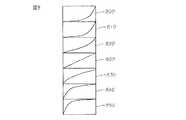
図7は、典型的な非直線的表現を例示する。非直線的表現700−750は、異なる方法で非直線的に減少する。典型的な非直線的表現は、指数および多項式の表現を含み、パワー、オン・タイムおよび/またはオフ・タイムは指数的にまたは多項式に従って、フットペダルの動きによって変化する。表現700−720およびパワー、オン・タイムおよび/またはオフ・タイムの対応する機能は、フットペダルが最初に押し下げられたときにより緩やかに減少し、フットペダルが更に押し下げられるにつれて、より急速に減少する。表現730−750およびパワー、オン・タイムおよび/またはオフ・タイムの対応する機能は、フットペダルが最初に押し下げられたときにより急速に減少して、フットペダルが更に押し下げられるにつれて、より緩やかに減少する。図8は、パワー、オン・タイムおよび/またはオフ・タイムの挙動または機能の増加表現に関して、類似の関係を例示する。 FIG. 7 illustrates a typical non-linear representation. Non-linear representation 700-750 decreases non-linearly in different ways. Typical non-linear representations include exponential and polynomial representations, where power, on time and / or off time varies with foot pedal movement either exponentially or according to a polynomial. Representation 700-720 and the corresponding function of power, on-time and / or off-time decreases more slowly when the foot pedal is first depressed, and decreases more rapidly as the foot pedal is further depressed . Representations 730-750 and the corresponding functions of power, on time and / or off time decrease more rapidly when the foot pedal is first depressed and decrease more slowly as the foot pedal is further depressed To do. FIG. 8 illustrates a similar relationship with respect to an increased representation of power, on-time and / or off-time behavior or function.
限定的でなく、説明および例示のために、この明細書は、例えば直線的増加、一定、および直線的減少表現、およびパワー、オン・タイムおよび/またはオフ・タイムに関連する直線的機能のような直線的表現に言及する。この技術に精通した者は、パワー、オン・タイムおよびオフ・タイムが直線的表現、非直線的表現、およびそれらの組合せにより制御できることを認識するであろう。この技術に精通した者はまた、直線的表現が、実質的に直線的であり、実用においては、若干の非直線的成分を含むパルス特性を表現できることも認識するであろう。例えば、実際のパワーおよびフットペダルの位置の関係は、フットペダル位置を、生成されるパワー量へマッピングするため、正確には直線的ではないこともある。このように、真の「直線的」表現からの若干の逸脱が、実用においてはマッピングおよび他の要素のために起こり得る。 For purposes of explanation and illustration, and not limitation, this specification may be used to describe, for example, linear increase, constant, and linear decrease expressions, and linear functions related to power, on time, and / or off time. Mention a straightforward expression. Those skilled in the art will recognize that power, on-time and off-time can be controlled by linear representations, non-linear representations, and combinations thereof. Those skilled in the art will also recognize that the linear representation is substantially linear, and in practice can represent pulse characteristics that include some non-linear components. For example, the actual power and foot pedal position relationship may not be exactly linear because it maps the foot pedal position to the amount of power generated. Thus, some deviation from the true “linear” representation can occur in practice due to mapping and other factors.
図6に示した実施形態において、直線的増加表現600は、表示要素の左下隅から右上隅まで伸び、フットペダルが押されると、表現されているパラメータが直線的に増加し、フットペダルがリリースされと、直線的に減少することを示す。水平または一定の直線的表現620は、表示要素の両方の対向する側の間に伸びて、表現されているパラメータが、種々のフットペダル位置においても、実質的に一定のままであることを示す。直線的減少表現610は、表示要素の左上隅から右下隅まで伸び、表現されているパラメータは、フットペダルが押されると直線的に減少し、フットペダルがリリースされると直線的に増加することを示す。別の実施例では、増加および直線的減少表現600および610と、パルスパラメータの対応する機能は、表示要素の一つの側と隅の間、または表示要素の両側の間に伸びてもよく、その場合もまた、増加または減少する関係を示す。これは、例えば、オン・タイムおよびオフ・タイムのようなパルスパラメータの開始値がゼロ以外の値であることを表現することもできる。In the embodiment shown in FIG. 6, the
図5を再度参照すると、パワー限界表示要素510はパワー限界または値513を含み、オン・タイム表示要素520はオン・タイム限界または値523を含み、オフ・タイム表示要素はオフ・タイム限界または値533を含む。限界は、それぞれの上下矢印514、524、および534または、スライドバーのような他の適切な調整機構(図5では図示せず)を使用して調整できる。本明細書は、限定的でなく、説明のために上下矢印に言及する。初期パワー、そして、最大値であっても最小値であってもよいオン・タイムおよびオフ・タイム値は、必要に応じて設定またはプログラムできる。例えば、システムは、フットペダルがリリースされているときのように、フットペダルがそのホームポジションにあるときに、最小パワー値が0%または他の所望値であるように構成できる。更なる例として、初期オン・タイムまたは、代替的に、最小値のオン・タイムは、0msまたはゼロ以外の値であり得る。同様に、初期オフ・タイムまたは、代替的に、最小値のオフ・タイムは、0msまたはゼロ以外の値であり得る。初期値または、代替的に、最小値は、他のインタフェース画面を使用するかまたはシステムに値をプログラムすることにより設定できる。最大パワー、オン・タイム、およびオフ・タイムもまた適切に設定またはプログラムできる。 Referring again to FIG. 5, the power
例えば、オン・タイムが増加する機能である場合(例えば、増加直線的機能)、オン・タイム限界523は、フットペダルが完全に押し下げられたときに達成できる最大オン・タイムを表現する。最小のオン・タイムは、ゼロまたは他の選択された値であり、例えば、最大値の20%であり得る。最小オン・タイムは、常套的な機能または他の技術を使用して決定できる。更なる例として、オン・タイムの機能が減少機能である場合、オン・タイム限界523は、フットペダルが完全に押し下げられたときに達成できる最小オン・タイム値を表現する。最大オン・タイムは適切に選択できる。類似の制御は、パワーおよびオフ・タイム限界にあてはまる。下記の例は、これらの関係を示す。 For example, if the on-time is a function that increases (eg, an increasing linear function), the on-
オン・タイムの最大値523が70msであり、オン・タイム表現522が直線的に増加すると、フットペダルが押されると、オン・タイムは、ゼロまたは最小値(例えば、70msの20%)から70msへと直線的に増加する。最小オン・タイムまたは開始点は、必要に応じて設定またはプログラムできる。更なる例として、オン・タイム表現522が直線的に減少する場合、フットペダルが押されるにつれて、オン・タイムは最大値から最小値の70msに直線的に減少する。最大オン・タイムまたは開始点は、必要に応じて設定またはプログラムできる。 If the on-
同様に、オフ・タイム限界533が70msであり、オフ・タイム表現532が直線的に減少する場合、フットペダルが押されるにつれて、オフ・タイムは最大値から70msに減少する。更なる例として、オフ・タイム表現が直線的に減少する場合、フットペダルが押されるにつれて、オフ・タイムは最大値から70msの最小値に減少する。 Similarly, if the
オフ・タイムの最大値が50msで、オフ・タイム表現が水平である場合は、オフ・タイムは異なるフットの高さ位置において、実質的に50msで一定に維持される。オン・タイムの最大値が50mで、オン・タイム表現が水平である場合、オン・タイムは異なるフットの高さ位置において、実質的に50msで一定に維持される。 If the maximum off time is 50 ms and the off time representation is horizontal, the off time remains substantially constant at 50 ms at different foot height positions. If the on-time maximum is 50 m and the on-time representation is horizontal, the on-time remains substantially constant at 50 ms at different foot height positions.
このように、パワー、オン・タイムおよびオフ・タイム表示要素510、520、および530のそれぞれにおける限界値513、523、および533は、フットペダルが押されたときにパラメータが増加するか、または減少するかに依存して、フットペダルが完全に押し下げられたときの各パラメータの最大または最小限界を表現する。限界値は、フットペダルが押されたときにパラメータが増加するときの最大値であり、フットペダルが押されたときにパラメータが減少するときの最小値である。 Thus, the limit values 513, 523, and 533 in the power, on-time and off-
示された実施形態では、値はそれぞれの表現の上にスーパーインポーズされる。換言すれば、表現は、表示要素のバックグラウンドに現れる。例えば、値513はパワー表現512の上にスーパーインポーズされ、値523はオン・タイム表現522の上にスーパーインポーズされ、値533はオフ・タイム表現532の上にスーパーインポーズされる。別の実施形態では、表現は表示設定に依存する値の上にスーパーインポーズすることもできる。In the illustrated embodiment, the value is superimposed on the respective representation. In other words, the representation appears in the background of the display element. For example,
外科医は、表現およびパワー、オン・タイム、およびオフ・タイムが異なる方法で機能する方法を選択することができ、切り替えることができる。図9を参照すると、一つの実施形態によれば、異なる表現のメニュー900がドロップダウンリストとして表示されるように、外科医は表示要素において表示画面にタッチすることができる。外科医はメニュー900から、パワー、オン・タイムおよび/またはオフ・タイムの新規な表現または機能を選択できる。例えば、図5および図9を参照すると、外科医は、オフ・タイム表示要素530において表示画面505にタッチすることができる。その結果、減少表現のメニュー900が表示され、外科医は表現のうちの1つをメニュー900から選択できる。選択された表現は、パルス特性がどのように機能するか示す。メニュー900は、減少、増加、および一定または水平の異なる数の表現を含むことができる。図9は、限定的でなく、説明のために、減少表現を有するメニュー900を例示する。パワー限界、オン・タイム、およびオフ・タイム表現のそれぞれは、メニュー900を使用して調整できる。 The surgeon can select and switch between ways in which expression and power, on-time, and off-time function in different ways. Referring to FIG. 9, according to one embodiment, the surgeon can touch the display screen on the display element so that a
図10を参照すると、他の実施形態によれば、外科医はスクロールメニュー1000を使用して、パルス特性の表現を所望の表現に変更するために、表示要素において表示画面505にタッチすることができる。このように、異なる表現は、図9に示すように、グループまたはメニュー900として示されるのではなく、個々に外科医に示される。本実施形態において、外科医が特定の表示要素において表示画面505にタッチするたびに、そのパルスパラメータの表現は、新規な表現に変化する。換言すれば、外科医は、対応する表示要素において表示画面505にタッチすることによって、パルス特性の異なる表現をスクロールすることができる。Referring to FIG. 10, according to another embodiment, the surgeon can use the
スクロールメニューの表現は、異なる順序で外科医に表示することができる。例えば、初期表現が水平表現である場合、表示要素への最初のタッチ(タッチ1)で水平表現を直線的増加表現に変更できる。次のタッチ(タッチ2)は、直線的増加表現を直線的減少表現に変更できる。次のタッチ(タッチ3)は、直線的増加表現を水平表現に変更できる。パワー限界、オン・タイム、およびオフ・タイム表現のそれぞれはこのような方法で調整できる。図10は、外科医が表示要素において表示画面にタッチすることに応答して、外科医に表現を表示することができる他のシーケンスを例示する。更に、別の実施形態は、表現の他の数の表現およびこのように、表示される表現の他のシーケンスを含むことができる。 The scroll menu representation can be displayed to the surgeon in a different order. For example, when the initial expression is a horizontal expression, the horizontal expression can be changed to a linear increase expression by the first touch (touch 1) on the display element. The next touch (Touch 2) can change the linear increase expression to a linear decrease expression. The next touch (touch 3) can change the linear increase representation to a horizontal representation. Each of the power limit, on-time, and off-time expressions can be adjusted in this way. FIG. 10 illustrates another sequence in which a representation can be displayed to the surgeon in response to the surgeon touching the display screen at the display element. Furthermore, other embodiments may include other numbers of representations and thus other sequences of displayed representations.
異なる超音波駆動またはパルスモードは、図9に示されるメニューまたは図10に示されるスクロールメニューを用いて、パワー、オン・タイム、およびオフ・タイムの機能または挙動の表現を選択することによって、水晶体超音波乳化吸引システムにより生成することができる。 Different ultrasonic drive or pulse modes can be selected by selecting the power, on-time, and off-time function or behavior representations using the menu shown in FIG. 9 or the scroll menu shown in FIG. It can be produced by an ultrasonic emulsification suction system.
一つ実施形態によれば、オン・タイムおよびオフ・タイムはそれぞれ、三つの異なる表現を割り当てることができる。つまり、直線的増加、直線的な水平または一定、および直線的減少である。図11を参照すると、可能なモードの総数は、オン・タイム表現の数とオフ・タイム表現の数を乗算することによって決定できる。本実施形態において、外科医は九つの異なるパルスモードをプログラムすることができる。実際には、異なる数の表現を使用すると、モードの数は変化する。 According to one embodiment, on-time and off-time can each be assigned three different representations. That is, linear increase, linear horizontal or constant, and linear decrease. Referring to FIG. 11, the total number of possible modes can be determined by multiplying the number of on-time representations and the number of off-time representations. In this embodiment, the surgeon can program nine different pulse modes. In practice, using a different number of representations will change the number of modes.
モード1においては、フットペダルが押されると、水平表現のため、オン・タイムおよびオフ・タイムの両者は実質的に一定のままである。モード2においては、押されているフットペダルに応答して、オン・タイムは実質的に一定のままであり、オフ・タイムは直線的に増加する。モード3においては、フットペダルを押すことに応答して、オン・タイムは実質的に一定のままであり、オフ・タイムは直線的に減少する。モード4においては、フットペダルを押すことに応答してオン・タイムは直線的に増加し、オフ・タイムは実質的に一定のままである。モード5においては、フットペダルが押されるにつれて、オン・タイムおよびオフ・タイムの両者は直線的に増加する。モード6においては、押されているフットペダルに応答して、オン・タイムは直線的に増加し、オフ・タイムは直線的に減少する。モード7においては、フットペダルを押すことに応答して、オン・タイムは直線的に減少し、オフ・タイムは実質的に一定のままである。モード8においては、押されているフットペダルに応答して、オン・タイムは直線的に減少し、オフ・タイムは直線的に増加する。モード9においては、フットペダルが押されると、オン・タイムおよびオフ・タイムの両者は直線的に減少する。外科医は、一つの実施例に係る特別な適用に依存して、九つのモードの一つを選択できる。図12−19は、選択されたモードの典型的な実施例を例示する。説明の目的のために、図12−19は、パワー、オン・タイム、およびオフ・タイム表現および関連した値だけを例示する。この技術に精通した者は、図12−図19で提供される値は、典型的な値であることを理解されよう。実際には、他のパワー、オン・タイムおよびオフ・タイム値を必要に応じて使用できる。従って、値は、制限的ではなく、説明の目的のために提供される。 In
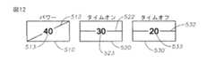
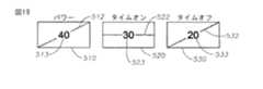
図12は、一般に「パルス」モードと呼ばれるモード1の典型的な実施例を例示する。「パルス」モードにおいて、水晶体超音波乳化吸引パワーは、一定のデューティサイクルで周期的なパルスで供給される。外科医は、固定幅のパルスの振幅を増減することになる、フットペダルを押す、またはリリースすることによって、パワーの量を増減する。周知のインタフェース、例えば図3に示されるインタフェースにおいて、「パルス」モードは、1秒当りのパルス数(pps)で表されるパルスレート、およびタイムオンの百分率で表されるデューティサイクルまたはオン・タイムを使用して典型的に設定される。本発明の実施形態は、「パルス」モードのパルスを表現するために、オン・タイムおよびオフ・タイムを使用する。図示の例においては、フットペダルが押し下げられるにつれて、パワーは初期または最小値から40%の最大値へ増加する。オン・タイムは、異なるフットペダルの位置全体を通して、30msで固定されたままであり、オフ・タイムは20msで固定されたままである。このように、固定幅または一定デューティサイクルパルスの振幅を調整することによりパワーは調整される。 FIG. 12 illustrates an exemplary embodiment of
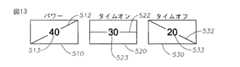
図13は、一般に「バースト」モードと呼ばれるモード3の典型的な実施例を示す。「バースト」モードにおいては、パワーは一連の周期的、および一定振幅のパルスを介して供給される。各パルスの後に、「オフ」タイムが続く。オフ・タイムは、ハンドピースに供給されるパワーの量を調整するために、フットペダルを押すことによって変化する。別のバーストモードにおいては、パルスの振幅もまた増加することもある。図示の例では、パワーは初期または最小値から40%の最大値まで直線的に増加する。オン・タイムは、フットペダルの異なる位置全体を通して固定または一定であり、オフ・タイムは初期または最大値から20msの最小値に直線的に減少する。バーストモードに対しては、初期値は、例えば2500msにプログラムまたは設定できる。実際には、特別な適用に依存して、他の初期値を使用することもできる。 FIG. 13 shows an exemplary embodiment of
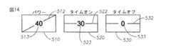
図14は、「連続」モードの一つの典型的な実施例を例示する。「パルス」モード(図12)または「バースト」モード(図13)以外のモードのときは、連続モードはオフ・タイムをゼロに設定することによって選択できる。フットペダルが押されるにつれてパワーがゼロから40まで直線的に増加するように、超音波パワーは「連続」モードにおいて、直線的な方法で連続的に印加される。FIG. 14 illustrates one exemplary embodiment of the “continuous” mode. When in a mode other than “pulse” mode (FIG. 12) or “burst” mode (FIG. 13), continuous mode can be selected by setting the off-time to zero. The ultrasonic power is continuously applied in a linearmanner in “continuous” mode so that the power increases linearly from zero to 40 as the foot pedal is pressed.
図15は、フットペダルが押されるにつれてオン・タイムが直線的に減少し、オフ・タイムが一定のままであるモードを例示する。より特別には、この組合せは結果として、初期または最小値から40%の最大値まで直線的に増加するパワーとなる。オン・タイムは、初期または最小値、例えば150msから30msの最小または終了値まで直線的に減少する。初期値は例えば、通常は「パルス」モードと呼ばれる、モード1の実施例を示している。このように、この例においては、150msの初期値は、30msの終了値の5倍である。オフ・タイムは、異なるフットペダルの位置全体を通して20msで固定されたままとなる。 FIG. 15 illustrates a mode in which the on-time decreases linearly and the off-time remains constant as the foot pedal is pressed. More specifically, this combination results in a power that increases linearly from an initial or minimum value to a maximum value of 40%. The on-time decreases linearly from an initial or minimum value, eg 150 ms to a minimum or end value of 30 ms. The initial values represent, for example, an embodiment of
システムにより生成されるパルスは、種々のレンズ(水晶体)硬度に「適応可能」であるため、図5に示される設定により生成されるモードは有益であり得る。例えば、外科医がフットペダルを、所与の分だけ押し下げても、結果としてレンズ除去が十分に迅速に進展しないということが分かると、外科医は一般的には、より深くフットペダルを押し下げることを命令し、このようにして、結果としてより大きなパワーを得る。通常、より大きなパワーは、より増大した反発力という結果になるが、しかしながら、この特定の設定を有する超音波パルスの持続期間が短くなるので、反発力は減少、最小化または、除去されることもある。外科医が、それらの硬度のためより高いパワーにおいてより反発の傾向がある、極めて成熟した白内障を抽出することを試みるときに、この結果は特別に役立つことがあり得る。 Since the pulses generated by the system are “adaptable” for various lens (lens) hardnesses, the mode generated by the settings shown in FIG. 5 may be beneficial. For example, if a surgeon finds that depressing the foot pedal by a given amount does not result in lens removal progressing quickly enough, the surgeon generally orders the foot pedal to be depressed deeper. In this way, more power is obtained as a result. Usually, higher power results in more repulsive force, however, the repulsive force is reduced, minimized or eliminated because the duration of the ultrasonic pulse with this particular setting is shortened. There is also. This result can be particularly useful when surgeons attempt to extract highly mature cataracts that tend to rebound at higher power due to their hardness.
図16は、パルスのパワーが初期または最小値から40%の最大値まで直線的に増加するモードを示している。オン・タイムは初期または最大値から30msの最小または終了値に直線的に減少する。上述したように、初期または最大値は、終了値の約5倍であり得る。このように、この例においては、初期または最大値は150msであり得る。オフ・タイムは2500msのような初期または最大値から20msの最小または終了値に直線的に減少する。 FIG. 16 shows a mode in which the power of the pulse increases linearly from the initial or minimum value to the maximum value of 40%. The on-time decreases linearly from an initial or maximum value to a minimum or ending value of 30 ms. As described above, the initial or maximum value may be about 5 times the end value. Thus, in this example, the initial or maximum value may be 150 ms. The off time decreases linearly from an initial or maximum value such as 2500 ms to a minimum or end value of 20 ms.
図17は、フットペダルが押されるにつれて、パワー、オン・タイム、およびオフ・タイムの全てが直線的に増加するモードを例示する。図示の例において、パワーは、初期または最小値から40%の最大または終了値まで直線的に増加する。オン・タイムは、例えば6msから20msの初期または最小値から、30msの最大または終了値まで直線的に増加する。オフ・タイムは、例えば4msの初期または最小値から20msの最大または終了値まで直線的に増加する。 FIG. 17 illustrates a mode in which power, on time, and off time all increase linearly as the foot pedal is pressed. In the example shown, the power increases linearly from an initial or minimum value to a maximum or end value of 40%. The on-time increases linearly, for example from an initial or minimum value of 6 ms to 20 ms, to a maximum or end value of 30 ms. The off time increases linearly, for example from an initial or minimum value of 4 ms to a maximum or end value of 20 ms.
図18はパワーおよびオン・タイムが直線的に増加し、オフ・タイムが直線的に減少するモードを例示する。パワーは、初期または最小値から40%の最大または終了値まで直線的に増加する。オン・タイムは、例えば6msの初期または最小値から30msの最大または終了値まで直線的に増加する。オフ・タイムは、例えば2500msの初期または最大値から20msの最小または終了値まで直線的に減少する。このモードの別の実施例が図5に示されている。 FIG. 18 illustrates a mode in which power and on-time increase linearly and off-time decreases linearly. The power increases linearly from an initial or minimum value to a maximum or ending value of 40%. The on-time increases linearly, for example from an initial or minimum value of 6 ms to a maximum or end value of 30 ms. The off time decreases linearly, for example from an initial or maximum value of 2500 ms to a minimum or end value of 20 ms. Another embodiment of this mode is shown in FIG.
図19は、パワーが初期または最小値から40%の最大または終了値まで直線的に増加するモードを示している。オン・タイムは、フットペダルの異なる位置全体を通して30msで一定のままである。オフ・タイムは、例えば4msの初期または最小値から20msの最大または終了値まで直線的に増加する。 FIG. 19 shows a mode in which the power increases linearly from an initial or minimum value to a maximum or end value of 40%. The on time remains constant at 30 ms throughout the different positions of the foot pedal. The off time increases linearly, for example from an initial or minimum value of 4 ms to a maximum or end value of 20 ms.
図20は、表現およびオン・タイムおよびオフ・タイム値が調整できる方法を例示する。ステップ2000において、水晶体超音波乳化吸引処置システムは、初期オン・タイム表現、初期オフ・タイム表現、初期オン・タイム値、および初期オフ・タイム値を有するように構成される。ステップ2005において、パルスモードまたはパルスパラメータの値を変更すべきかどうかの決定がなされる。変更すべきでないと決定された場合は、初期の設定は維持される。 FIG. 20 illustrates how the representation and on-time and off-time values can be adjusted. In
パルスモードが変更されることになった場合は、ステップ2010においてオン・タイムおよびオフ・タイム表現はステップ2015および2020で必要に応じて変更される。例えば、外科医は、オン・タイム表現を直線的増加、一定、または直線的減少表現のうちの一つに変更するために、オン・タイム表示要素において表示画面にタッチすることができる。同様に、外科医は、オフ・タイム表現を直線的増加、一定、または直線的減少表現のうちの一つに変更するために、オフ・タイム表示要素において表示画面にタッチすることができる。オン・タイムおよびオフ・タイム機能の選択された組合せは、結果としてステップ2025において選択されている図11に示されるパルスモードのうちの一つになる。もちろん、異なる表現の数により、外科医は異なる数のパルスモードを生成することが可能になる。 If the pulse mode is to be changed, in
オン・タイムおよびオフ・タイムパラメータの値は、ステップ2030において調整できる。より特別には、オン・タイム値およびオフ・タイム値は、ステップ2035および2040において、必要に応じて調整できる。このように、パルスモードの値は、必要に応じてステップ2045において調整できる。 The values of the on time and off time parameters can be adjusted in
図21は、一つの実施形態による、パラメータの値と表現の調整方法を示している。ステップ2100において、インタフェースまたはインタフェース画面が生成される。インタフェースは、水晶体超音波乳化吸引外科用システムのオン・タイムおよびオフ・タイム(または、非超音波パラメータ)のようなパラメータを表現する表示要素を含む。ステップ2110において、ユーザーは、表示要素または他の予め定義された領域などにおいて、表示の画面にタッチする。ステップ2120において、表示画面にタッチすることに応答してウィンドウが生成される。ウィンドウにより、ユーザーは、ステップ2130において、パラメータの機能の表現またはパラメータの値を調整できる。 FIG. 21 illustrates a parameter value and expression adjustment method according to one embodiment. In
ステップ2140−ステップ2155は、パラメータの機能の表現の変更を示している。ステップ2145において、ユーザーは表示要素において表示画面にタッチして表現を調整する。調整は表現をステップ2150において、増加、一定、または減少にするおよび/または表現を直線または非直線に変更することであり得る。
ステップ2160−ステップ2175は、パラメータの値の変更を示している。ステップ2165において、ユーザーは、表示要素において表示画面にタッチして、値を調整する。調整は、ステップ2170において、上/下矢印のような矢印を使用および/またはステップ2175においてスライドバーを使用して行える。表現と限界値の両者を調整するときは、表現を先に調整し、その後に値を調整できる。または、限界値を先に調整し、その後に表現を調整することもできる。 Steps 2160 to 2175 indicate changes in parameter values. In
ステップ2180において、パラメータの表現および/または値の調整後に、ウィンドウは、ウィンドウの予め定義された領域において表示画面にタッチすることにより閉じることができる。ステップ2185において、ウィンドウは閉じられ、インタフェースは、更新された表示要素を含む。必要ならば、同様な方法で更に調整することができる。 In
図22−図30を参照すると、他のポップアップまたはダイアログウィンドウ構成を、別の実施形態と共に利用できる。ウィンドウは、上記の同様な方法で生成できる。更に、上記のように、ウィンドウを、振幅、真空、洗浄、感度、パルスレート、パルスオン・タイム、パルスオフ・タイム、凝固、および閾値を含む種々の超音波および非超音波パラメータの調整に使用できる。 Referring to FIGS. 22-30, other pop-up or dialog window configurations can be utilized with alternative embodiments. Windows can be generated in a similar manner as described above. Further, as described above, the window can be used to adjust various ultrasonic and non-ultrasonic parameters including amplitude, vacuum, cleaning, sensitivity, pulse rate, pulse on time, pulse off time, coagulation, and threshold.
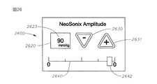
図22−図30は、本発明の別の実施形態を示しており、眼外科用システムの表示画面にタッチすることに応答してウィンドウを生成することができ、それにより、ユーザーは、パルスモードを変更し、パラメータの値および/またはパラメータの機能または表現を調整できる。図22−図30に示された実施形態は、図5−図21に記述され、示された実施形態とは分離して、または一緒に使用することができる。ウィンドウは、振幅、感度、パルスレート、真空、洗浄、パルスオン・タイム、パルスオフ・タイム、凝固、および閾値を含む、眼外科用システムの種々の態様の超音波および非超音波パラメータを調整するために使用できる。例えば、図22を参照すると、眼外科用システムのための典型的なユーザーインタフェース画面2200は、フィールド2210と表示要素2220を含む。表示要素2220は、例えば、凝固パワーのような非超音波パラメータの表現2222と、パラメータの最大または最小値または限界2223を含む。示された実施形態において、値は、表現が、フットペダルが押されると、または他のコントローラが起動されるとパワーが増加することを示しているので、最大値となる。限界2223の百分率で表わされるパラメータの現在の値2213は、フィールド2210に示されている。 FIGS. 22-30 illustrate another embodiment of the present invention that can generate a window in response to touching the display screen of an ophthalmic surgical system so that the user can use pulse mode. Can be changed to adjust the value of the parameter and / or the function or representation of the parameter. The embodiment shown in FIGS. 22-30 can be used separately or together with the embodiment described in FIGS. 5-21 and shown. A window to adjust ultrasonic and non-ultrasonic parameters of various aspects of the ophthalmic system including amplitude, sensitivity, pulse rate, vacuum, wash, pulse on time, pulse off time, coagulation, and threshold Can be used. For example, referring to FIG. 22, an exemplary
表示要素2220は、フットペダルのようなコントローラの位置に関するパラメータの挙動または機能の表現2222を含む。パラメータの表現2222は、パラメータとフットペダルの位置の所望の関係または機能に依存して、種々の形状を有することができる。例えば、表現2222は、直線的または非直線的(例えば、指数または多項式)であり得る。表示要素2220は、上述した表示要素と類似している。従って、表示要素2220に関しての追加的詳細は繰り返さない。更に、制限的ではなく、説明および例示の目的のために、本明細書は、例えば、直線的増加、一定、および直線的減少表現と、パワーの関連する直線的機能のような直線的表現に言及する。この技術に精通した者は、オン・タイムおよびオフ・タイムのような他のパラメータは制御でき、パラメータ直線的表現、非直線的表現、およびその組合せにより制御できることを理解されよう。The
図23を参照すると、一つの実施形態によれば、ポップアップまたはダイアログウィンドウ2300は、例えば、表示要素2220において、またはその周りなどにおいて、ユーザーが表示画面にタッチすることに応答して、初期表示画面2200上に表示される。ウィンドウ2300は、ウィンドウ2300の背後の、初期表示画面2200上の表示要素2220の表現2222と同様な表現2322を有する表示要素2320を含む。ウィンドウ2300はまた、ウィンドウ2300の背後の、表示画面2200における値2223と同じである、最大値または限界2323を含む。ウィンドウ2300は種々の形状およびサイズであり得る。示された実施形態においては、ウィンドウ2300は正方形であり、初期表示2200の一部を覆っている。Referring to FIG. 23, according to one embodiment, the pop-up or
ウィンドウ2300はまた、上/下矢印2330と2331(まとめて2330)のような矢印や、スライドバー2340のような一つまたは二つ以上の調整要素も含む。ウィンドウ2300は、複数の矢印、スライドバー、およびそれらの組合せを含むことができる。
図24を参照すると、ユーザーは矢印2330にタッチし、またはスライドバー2340のマーカー2342を動かして、値の増減を調整できる。例えば、図23と図24に示すように、上矢印2331を押し、またはマーカー2342を右に動かすことにより値を30から80に調整できる。図25を参照すると、パラメータの機能の表現もまた、ウィンドウ2300における表示要素2320において表示画面505にタッチすることにより調整できる。ウィンドウ2300における表示要素2320にタッチすると、パラメータの現在の表現が異なる表現に変更される。例えば、図10に示すように、ユーザーはウィンドウにおける表示要素にタッチすることにより、異なる利用可能な表現をスクロールできる。または、図9に示すように、メニューまたはピックリストを表示することができる。Referring to FIG. 24, the user can adjust the value increase or decrease by touching the
図24と図25を参照すると、パラメータの表現および/または値を調整した後、ウィンドウは、ウィンドウの予め定義された領域2400において表示画面にタッチすることにより閉じることができる。例えば、示された実施形態においては、予め定義された領域2400は、ウィンドウにおける「OK」ボックスまたはボタン、または他の領域であってよい。 Referring to FIGS. 24 and 25, after adjusting the representation and / or values of the parameters, the window can be closed by touching the display screen in a
図26−図30を参照すると、他のポップアップまたはダイアログウィンドウの構成は、他の実施形態と共に利用できる。ウィンドウは、上述したものと同様な方法で生成できる。更に、上述したようにウィンドウは、異なる眼外科処置のための振幅、真空、洗浄、感度、パルスレート、パルスオン・タイム、パルスオフ・タイム、凝固、および閾値を含む、種々の超音波および非超音波パラメータを調整するために使用できる。例示と説明の目的のために、図26−図30は、硝子体網膜外科処置に言及する。 Referring to FIGS. 26-30, other pop-up or dialog window configurations can be utilized with other embodiments. The window can be generated in the same way as described above. In addition, as described above, the window can include a variety of ultrasound and non-ultrasound, including amplitude, vacuum, irrigation, sensitivity, pulse rate, pulse on time, pulse off time, coagulation, and threshold for different ophthalmic surgical procedures. Can be used to adjust parameters. For purposes of illustration and description, FIGS. 26-30 refer to a vitreous retinal surgical procedure.
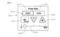
図26を参照すると、硝子体網膜外科用システムのためのポップアップまたはダイアログウィンドウ2600は、表示要素2620と、上/下矢印2630と2631のような、一つまたは二つ以上の調整要素を含むことができる。表示要素2620のパラメータの値2623は、ユーザーが上/下矢印2630と2631を押すと変更される。パラメータはまた、パラメータの値を調整するために、スライドバー2640のマーカー2642を動かすことで調整できる。パラメータの値は、ユーザーが矢印またはスライドバーを使用して調整を行うことで変更できる。ポップアップまたはダイアログウィンドウは、例えば、画面に最後にタッチした後に、予め決められた時間が経過したときのように、アクティブでない時間が予め決められた時間だけ経過すると徐々に消えていく、即ち、閉じるようにすることができる。限定的でなく、例示と説明の目的で、図26は真空または吸引レベルの調整を示す。 Referring to FIG. 26, a pop-up or
図27を参照すると、ポップアップまたはダイアログウィンドウ2700もまた、調整が完了したことを示す選択要素2710を含むことができる。例えば、選択要素2710は、「キャンセル」および「終了」ボタン2711と2712であってよい。ユーザーは「終了」ボタン2712を押した後に、ウィンドウを閉じることができる。「キャンセル」ボタンは、更なる調整が必要な場合、または調整が正しくない場合に押すことができる。このように、「終了」および「キャンセル」ボタンを含むウィンドウにより、パラメータの値は、ユーザーがパラメータの変更は「終了」ボタンを押すことにより実行できることを確認後に変更され、その後、ポップアップウィンドウまたはダイアログボックスは表示画面から消える。 Referring to FIG. 27, the pop-up or
図28を参照すると、ウィンドウ2800もまた、ユーザーが外科用システムの機能をイネーブルまたはディスエーブルにできる、イネーブル要素2810を含むことができる。示された実施形態においては、イネーブル要素は、「ディスエーブル」ボタン2811と、「イネーブル」ボタン2812を含む。更に、図28は、表示要素2620、矢印2630と2631、およびスライドバー2640の別の配置を示している。図28に示されたウィンドウは、図26に示されたウィンドウと類似しているが、アクティブでない時間が予め決められた時間だけ経過すると徐々に消えていく、即ち、閉じる。 Referring to FIG. 28, the
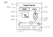
図29は、上述した機能の組合せを有するウィンドウの更なる実施形態を示している。特に、図29に示されたウィンドウ2900は、表示要素2620、矢印2630と2631、スライドバー2640、「ディスエーブル」と「イネーブル」ボタン2811と2812、および「キャンセル」および「終了」ボタン2711と2712を含む。図29は、これらのウィンドウ要素の更に別の配置を示している。FIG. 29 shows a further embodiment of a window having a combination of the functions described above. In particular,
図30を参照すると、ウィンドウ3000の他の実施形態は、調整されるパラメータの種々の値を示すドロップダウンメニューまたはピックアップリスト3010を含む。上述の調整の代替として、または追加的オプションとして、ユーザーは、所望の値を選択するために、メニューオプション3011−3015の一つを選択できる。 Referring to FIG. 30, another embodiment of
図26−図30に示されたポップアップまたはダイアログウィンドウの態様はまた、水晶体超音波乳化吸引および他の処置のような、他の外科処置のための、ポップアップまたはダイアログウィンドウに適用可能である。例えば、水晶体超音波乳化吸引外科用システムのためのユーザーインタフェースにおけるポップアップまたはダイアログウィンドウは、アクティブでない時間が予め決められた時間だけ経過すると徐々に消えていく、即ち、閉じるようにすることができる。または、ユーザーは、ユーザーが必要な調整を完了したことを示す「終了」ボタンまたは他の適切なボタンを押すことにより、ウィンドウを閉じることができる。 The pop-up or dialog window embodiment shown in FIGS. 26-30 is also applicable to pop-up or dialog windows for other surgical procedures, such as phacoemulsification and other procedures. For example, a pop-up or dialog window in a user interface for a phacoemulsification suction surgical system may gradually disappear, i.e., close after a predetermined period of inactivity. Alternatively, the user can close the window by pressing an “Exit” button or other appropriate button that indicates that the user has completed the necessary adjustments.
この技術に精通した者は、グラフィカルユーザーインタフェースおよびオン・タイムおよびオフ・タイムの調整が種々の方法で修正できることを認識するだろう。従って、この技術に精通した者は、実施形態が、記載されている特定の例示的実施形態に制限されないこと認識し、むしろ、実施形態は他の外科装置およびパラメータに適用できることを認識するであろう。例えば、実施形態は、水晶体超音波乳化吸引および硝子体網膜装置に加えて、凝固用鉗子および硝子体切除プローブのような他の外科用装置と共に使用することができる。前述の記述において、種々の実施形態への参照がなされたが、この技術に精通した者は、本質的でない変形、変更および置換が、添付の請求の範囲に詳述された本発明から逸脱することなく、記載されている実施例になされるということを認識するであろう。 Those skilled in the art will recognize that the graphical user interface and on-time and off-time adjustments can be modified in various ways. Thus, those skilled in the art will recognize that the embodiments are not limited to the specific exemplary embodiments described, but rather recognize that the embodiments are applicable to other surgical devices and parameters. Let's go. For example, embodiments can be used with other surgical devices such as coagulation forceps and vitrectomy probes in addition to phacoemulsification and vitreal retinal devices. While reference has been made to various embodiments in the foregoing description, those skilled in the art will appreciate that non-essential variations, modifications and substitutions depart from the invention as detailed in the appended claims. It will be appreciated that this is done without the described embodiment.
Claims (18)
Translated fromJapanese前記表示画面上に示され、前記コントローラの位置に関して、前記眼外科用システムにより生成されるパルスのパラメータの機能のグラフィック表現を含む表示要素と、
前記表示画面上に表示され、前記表示画面にタッチすることに応答して生成されるウィンドウであって、前記コントローラの前記位置に関する前記パルスの前記パラメータの機能のグラフィック表現を有する表示要素を含むウィンドウと、を備え、
前記ウィンドウに表示される前記パラメータの機能の現在のグラフィック表現は、前記ウィンドウにおいて前記表示画面にタッチすること、または、前記表示要素において前記表示画面にタッチすることに応答して、異なるグラフィック表現に変更されるユーザーインタフェース。A user interface for the ophthalmic surgical system in response to a controller that generates pulses that are adjusted based on settings displayed on a display screen of the ophthalmic surgical system;
A display element shown on the display screen and includinga graphical representation of thefunction of the parameters of the pulse generated by the ophthalmic system with respect to the position of the controller;
A window displayed on the display screen and generated in response to touching the display screen, the window including a display element havinga graphical representation of thefunction of the parameter of the pulse with respect to the position of the controller and, witha,
The current graphical representation of the function of the parameter displayed in the window is a different graphical representation in response to touching the display screen in the window or touching the display screen in the display element. The user interfaceto be changed .
Applications Claiming Priority (6)
| Application Number | Priority Date | Filing Date | Title |
|---|---|---|---|
| US67187905P | 2005-04-15 | 2005-04-15 | |
| US60/671,879 | 2005-04-15 | ||
| US11/170,952 | 2005-06-30 | ||
| US11/170,952US7945341B2 (en) | 2004-11-30 | 2005-06-30 | Graphical user interface for selecting pulse parameters in a phacoemulsification surgical system |
| US11/193,159 | 2005-07-29 | ||
| US11/193,159US7983771B2 (en) | 2004-11-30 | 2005-07-29 | Graphical user interface including a pop up window for an ocular surgical system |
Publications (3)
| Publication Number | Publication Date |
|---|---|
| JP2006297087A JP2006297087A (en) | 2006-11-02 |
| JP2006297087A5 JP2006297087A5 (en) | 2009-05-28 |
| JP4955296B2true JP4955296B2 (en) | 2012-06-20 |
Family
ID=37114193
Family Applications (3)
| Application Number | Title | Priority Date | Filing Date |
|---|---|---|---|
| JP2006112042APendingJP2006297085A (en) | 2005-04-15 | 2006-04-14 | Graphical user interface for selecting pulse parameter in crystal lens ultrasonic emulsification suction surgery system |
| JP2006112059AActiveJP4943732B2 (en) | 2005-04-15 | 2006-04-14 | Graphical user interface for phacoemulsification aspiration surgical system |
| JP2006112081AActiveJP4955296B2 (en) | 2005-04-15 | 2006-04-14 | Graphical user interface including pop-up window for ophthalmic surgical systems |
Family Applications Before (2)
| Application Number | Title | Priority Date | Filing Date |
|---|---|---|---|
| JP2006112042APendingJP2006297085A (en) | 2005-04-15 | 2006-04-14 | Graphical user interface for selecting pulse parameter in crystal lens ultrasonic emulsification suction surgery system |
| JP2006112059AActiveJP4943732B2 (en) | 2005-04-15 | 2006-04-14 | Graphical user interface for phacoemulsification aspiration surgical system |
Country Status (9)
| Country | Link |
|---|---|
| US (4) | US7945341B2 (en) |
| EP (4) | EP1712211B1 (en) |
| JP (3) | JP2006297085A (en) |
| AT (4) | ATE427088T1 (en) |
| AU (4) | AU2006201577B2 (en) |
| BR (3) | BRPI0601455A (en) |
| CA (3) | CA2542591C (en) |
| DE (4) | DE602006005974D1 (en) |
| ES (4) | ES2323278T3 (en) |
Families Citing this family (63)
| Publication number | Priority date | Publication date | Assignee | Title |
|---|---|---|---|---|
| US9119700B2 (en) | 2004-11-30 | 2015-09-01 | Novartis Ag | Graphical user interface system and method for representing and controlling surgical parameters |
| US7945341B2 (en)* | 2004-11-30 | 2011-05-17 | Alcon, Inc. | Graphical user interface for selecting pulse parameters in a phacoemulsification surgical system |
| CA2803828C (en) | 2005-03-31 | 2015-11-24 | Alcon, Inc. | Footswitch operable to control a surgical system |
| US8380126B1 (en) | 2005-10-13 | 2013-02-19 | Abbott Medical Optics Inc. | Reliable communications for wireless devices |
| US8565839B2 (en) | 2005-10-13 | 2013-10-22 | Abbott Medical Optics Inc. | Power management for wireless devices |
| JP2009528144A (en)* | 2006-02-27 | 2009-08-06 | アルコン,インコーポレイティド | System and method for treatment-based graphical interface |
| US8272387B2 (en) | 2006-06-30 | 2012-09-25 | Novartis Ag | System and method for the modification of surgical procedures using a graphical drag and drop interface |
| US8982195B2 (en) | 2006-09-07 | 2015-03-17 | Abbott Medical Optics Inc. | Digital video capture system and method with customizable graphical overlay |
| US8287523B2 (en) | 2006-09-07 | 2012-10-16 | Abbott Medical Optics Inc. | Systems and methods for historical display of surgical operating parameters |
| US10959881B2 (en) | 2006-11-09 | 2021-03-30 | Johnson & Johnson Surgical Vision, Inc. | Fluidics cassette for ocular surgical system |
| US8491528B2 (en) | 2006-11-09 | 2013-07-23 | Abbott Medical Optics Inc. | Critical alignment of fluidics cassettes |
| US9522221B2 (en) | 2006-11-09 | 2016-12-20 | Abbott Medical Optics Inc. | Fluidics cassette for ocular surgical system |
| US9295765B2 (en) | 2006-11-09 | 2016-03-29 | Abbott Medical Optics Inc. | Surgical fluidics cassette supporting multiple pumps |
| US8414534B2 (en) | 2006-11-09 | 2013-04-09 | Abbott Medical Optics Inc. | Holding tank devices, systems, and methods for surgical fluidics cassette |
| US8465473B2 (en) | 2007-03-28 | 2013-06-18 | Novartis Ag | Surgical footswitch with movable shroud |
| USD602945S1 (en)* | 2007-04-20 | 2009-10-27 | Sony Computer Entertainment Inc. | Computer generated image for display panel or screen |
| US10485699B2 (en) | 2007-05-24 | 2019-11-26 | Johnson & Johnson Surgical Vision, Inc. | Systems and methods for transverse phacoemulsification |
| US10596032B2 (en) | 2007-05-24 | 2020-03-24 | Johnson & Johnson Surgical Vision, Inc. | System and method for controlling a transverse phacoemulsification system with a footpedal |
| US10363166B2 (en) | 2007-05-24 | 2019-07-30 | Johnson & Johnson Surgical Vision, Inc. | System and method for controlling a transverse phacoemulsification system using sensed data |
| GR1006435B (en)* | 2007-06-07 | 2009-06-15 | Μιχαηλ Θεμελη Σιδερης | Ultrasound diathermy system of completely controlled operation. |
| US10342701B2 (en) | 2007-08-13 | 2019-07-09 | Johnson & Johnson Surgical Vision, Inc. | Systems and methods for phacoemulsification with vacuum based pumps |
| US20090049397A1 (en)* | 2007-08-15 | 2009-02-19 | Mikhail Boukhny | System And Method For A Simple Graphical Interface |
| US7981109B2 (en) | 2007-08-15 | 2011-07-19 | Novartis Ag | System and method for a user interface |
| US9314553B2 (en)* | 2008-01-10 | 2016-04-19 | Alcon Research, Ltd. | Surgical system |
| EP2304555A2 (en)* | 2008-06-05 | 2011-04-06 | Alcon Research, Ltd. | Wireless network and methods of wireless communication for ophthalmic surgical consoles |
| WO2010054145A1 (en) | 2008-11-07 | 2010-05-14 | Abbott Medical Optics Inc. | Surgical cassette apparatus |
| AU2009313402C1 (en) | 2008-11-07 | 2015-10-15 | Johnson & Johnson Surgical Vision, Inc. | Automatically switching different aspiration levels and/or pumps to an ocular probe |
| US9795507B2 (en) | 2008-11-07 | 2017-10-24 | Abbott Medical Optics Inc. | Multifunction foot pedal |
| EP2373265B1 (en) | 2008-11-07 | 2016-03-09 | Abbott Medical Optics Inc. | Controlling of multiple pumps |
| CA2743086C (en) | 2008-11-07 | 2017-12-05 | Abbott Medical Optics Inc. | Automatically pulsing different aspiration levels to an ocular probe |
| EP3156012B1 (en) | 2008-11-07 | 2021-10-20 | Johnson & Johnson Surgical Vision, Inc. | Adjustable foot pedal control for ophthalmic surgery |
| US10349925B2 (en) | 2008-11-07 | 2019-07-16 | Johnson & Johnson Surgical Vision, Inc. | Method for programming foot pedal settings and controlling performance through foot pedal variation |
| EP2341878B1 (en) | 2008-11-07 | 2017-06-21 | Abbott Medical Optics Inc. | Semi-automatic device calibraton |
| US9492317B2 (en) | 2009-03-31 | 2016-11-15 | Abbott Medical Optics Inc. | Cassette capture mechanism |
| US10453571B2 (en)* | 2009-12-21 | 2019-10-22 | Alcon Research, Llc | Event driven configuration of a surgical system console |
| US20110238431A1 (en)* | 2010-03-23 | 2011-09-29 | Robert Cionni | Surgical Console Information Management |
| TWI522085B (en)* | 2010-04-14 | 2016-02-21 | 愛爾康研究有限公司 | Display for ophthalmic surgical console with user-selectable sectors |
| EP2715499B1 (en)* | 2011-05-23 | 2020-09-02 | Microsoft Technology Licensing, LLC | Invisible control |
| US20120302941A1 (en) | 2011-05-23 | 2012-11-29 | Dan Teodorescu | Phacoemulsification systems and associated user-interfaces and methods |
| US9259354B2 (en) | 2011-06-09 | 2016-02-16 | KeLoTec, Inc. | Laser delivery system for eye surgery |
| US20150273243A1 (en)* | 2014-03-28 | 2015-10-01 | Carl Zeiss Meditec Ag | Ophthalmic surgical pulse control apparatus |
| US8986290B2 (en)* | 2011-10-06 | 2015-03-24 | Douglas Patton | Systems and methods for combined femto-phaco cataract surgery |
| WO2013142009A1 (en) | 2012-03-17 | 2013-09-26 | Abbott Medical Optics, Inc. | Surgical cassette |
| JP6527821B2 (en) | 2012-06-03 | 2019-06-05 | マケ クリティカル ケア エービー | Breathing apparatus and method of user interaction with the apparatus |
| NL2009424C2 (en) | 2012-09-06 | 2014-03-10 | D O R C Dutch Ophthalmic Res Ct International B V | Irrigation/aspiration system, cartridge, pump unit, surgical machine, method for controlling. |
| USD733181S1 (en)* | 2012-10-09 | 2015-06-30 | Shenzhen Mindray Bio-Medical Electronics Co. Ltd. | Anesthesia machine with animated graphical user interface |
| US9681982B2 (en) | 2012-12-17 | 2017-06-20 | Alcon Research, Ltd. | Wearable user interface for use with ocular surgical console |
| US9730835B2 (en) | 2012-12-19 | 2017-08-15 | Novartis Ag | Burst mode vitrectomy system |
| USD746856S1 (en)* | 2013-02-07 | 2016-01-05 | Tencent Technology (Shenzhen) Company Limited | Display screen portion with an animated graphical user interface |
| GB2533503B (en)* | 2013-08-19 | 2020-09-16 | Fisher & Paykel Healthcare Ltd | A user interface and method of operating same |
| US20150057774A1 (en)* | 2013-08-22 | 2015-02-26 | Novartis Ag | Graphical user interface for surgical console |
| TWI539331B (en)* | 2014-03-03 | 2016-06-21 | 宏碁股份有限公司 | Electronic device and user interface control method |
| US9974689B2 (en) | 2014-11-06 | 2018-05-22 | Novartis Ag | Dual mode vitrectomy surgical system |
| AU2016354489A1 (en)* | 2015-11-11 | 2018-06-07 | Johnson & Johnson Surgical Vision, Inc. | Systems and methods for providing virtual access to a surgical console |
| US12350198B2 (en) | 2016-09-28 | 2025-07-08 | Lensar, Inc. | Systems for laser eye surgery |
| US11937954B2 (en) | 2016-10-21 | 2024-03-26 | Lensar, Inc. | Systems and methods for combined Femto-Phaco surgery |
| US11957620B2 (en) | 2018-10-03 | 2024-04-16 | Johnson & Johnson Surgical Vision, Inc. | Learning auto phaco phacoemulsification mode for ophthalmic surgery |
| US11141313B2 (en) | 2018-10-03 | 2021-10-12 | Johnson & Johnson Surgical Vision, Inc. | Systems and methods for automated phacoemulsification |
| US11751953B2 (en) | 2019-05-03 | 2023-09-12 | Lensar, Inc. | Cloud based system cataract treatment database and algorithm system |
| CN114423353B (en)* | 2019-10-16 | 2024-07-30 | 深圳迈瑞生物医疗电子股份有限公司 | Endoscope camera host, mode setting method, system and storage medium thereof |
| CA3163569A1 (en) | 2020-01-03 | 2021-07-08 | Gary P. Gray | Integrated systems for predetermined combination laser-phacoemulsification therapies |
| DE102020105834A1 (en)* | 2020-03-04 | 2021-09-09 | Olympus Winter & Ibe Gmbh | Method and system for supporting HF and / or US surgical interventions and software program product |
| US20230039808A1 (en) | 2021-08-07 | 2023-02-09 | Johnson & Johnson Surgical Vision, Inc. | Electronically detecting phacoemulsification tip engagement with a lens |
Family Cites Families (67)
| Publication number | Priority date | Publication date | Assignee | Title |
|---|---|---|---|---|
| US4827911A (en)* | 1986-04-02 | 1989-05-09 | Cooper Lasersonics, Inc. | Method and apparatus for ultrasonic surgical fragmentation and removal of tissue |
| JPS6366984A (en)* | 1986-09-08 | 1988-03-25 | Matsushita Electric Ind Co Ltd | Semiconductor laser logic circuit |
| US4933843A (en)* | 1986-11-06 | 1990-06-12 | Storz Instrument Company | Control system for ophthalmic surgical instruments |
| US5157603A (en)* | 1986-11-06 | 1992-10-20 | Storz Instrument Company | Control system for ophthalmic surgical instruments |
| US4812996A (en)* | 1986-11-26 | 1989-03-14 | Tektronix, Inc. | Signal viewing instrumentation control system |
| US5371851A (en)* | 1989-04-26 | 1994-12-06 | Credence Systems Corporation | Graphical data base editor |
| US5249121A (en)* | 1989-10-27 | 1993-09-28 | American Cyanamid Company | Remote control console for surgical control system |
| US5898434A (en)* | 1991-05-15 | 1999-04-27 | Apple Computer, Inc. | User interface system having programmable user interface elements |
| AU2366092A (en)* | 1991-07-31 | 1993-03-02 | Mentor O&O, Inc. | Controlling operation of handpieces during ophthalmic surgery |
| US5554894A (en)* | 1994-10-28 | 1996-09-10 | Iolab Corporation | Electronic footswitch for ophthalmic surgery |
| AU4006895A (en) | 1994-10-28 | 1996-05-23 | Chiron Vision Corporation | Control system for opthalmic surgery |
| US5764317A (en)* | 1995-06-26 | 1998-06-09 | Physical Optics Corporation | 3-D volume visualization display |
| US6169540B1 (en)* | 1995-12-01 | 2001-01-02 | Immersion Corporation | Method and apparatus for designing force sensations in force feedback applications |
| JP3784110B2 (en)* | 1996-07-30 | 2006-06-07 | 東京エレクトロン株式会社 | Processing equipment |
| JP3122618B2 (en)* | 1996-08-23 | 2001-01-09 | 東京エレクトロン株式会社 | Plasma processing equipment |
| US6251113B1 (en)* | 1996-08-29 | 2001-06-26 | Bausch & Lomb Surgical, Inc. | Ophthalmic microsurgical system employing surgical module employing flash EEPROM and reprogrammable modules |
| DE69728793T2 (en)* | 1996-08-29 | 2004-09-23 | Bausch & Lomb Surgical, Inc. | FREQUENCY AND POWER CONTROL ARRANGEMENT WITH DOUBLE CIRCLE |
| US5910139A (en)* | 1996-08-29 | 1999-06-08 | Storz Instrument Co. | Numeric keypad simulated on touchscreen |
| US5997528A (en)* | 1996-08-29 | 1999-12-07 | Bausch & Lomb Surgical, Inc. | Surgical system providing automatic reconfiguration |
| US5877957A (en)* | 1996-11-06 | 1999-03-02 | Ameritech Services, Inc. | Method and system of programming at least one appliance to change state upon the occurrence of a trigger event |
| AU5514898A (en) | 1996-12-11 | 1998-07-03 | Chiron Vision Corporation | Remote control for ophthalmic surgical control console |
| US6629948B2 (en)* | 1997-01-22 | 2003-10-07 | Advanced Medical Optics | Rapid pulse phaco power for burn free surgery |
| US7169123B2 (en)* | 1997-01-22 | 2007-01-30 | Advanced Medical Optics, Inc. | Control of pulse duty cycle based upon footswitch displacement |
| DE19880536B4 (en)* | 1997-03-11 | 2004-08-05 | Mitsubishi Denki K.K. | Visual programming method and programming system using this method |
| US5853367A (en)* | 1997-03-17 | 1998-12-29 | General Electric Company | Task-interface and communications system and method for ultrasound imager control |
| US6179829B1 (en)* | 1997-08-28 | 2001-01-30 | Bausch & Lomb Surgical, Inc. | Foot controller for microsurgical system |
| JPH1170121A (en)* | 1997-08-29 | 1999-03-16 | Nidek Co Ltd | Laser treatment device |
| JP3976913B2 (en)* | 1997-11-10 | 2007-09-19 | 株式会社ニデック | Ophthalmic surgery equipment |
| US6066129A (en)* | 1998-01-29 | 2000-05-23 | Larson; Dean W. | Medical laser control system |
| JP4436899B2 (en)* | 1998-02-27 | 2010-03-24 | 株式会社ニデック | Ophthalmic surgery equipment |
| US6229536B1 (en)* | 1998-03-05 | 2001-05-08 | Agilent Technologies, Inc. | System and method for displaying simultaneously a main waveform display and a magnified waveform display in a signal measurement system |
| US6554798B1 (en)* | 1998-08-18 | 2003-04-29 | Medtronic Minimed, Inc. | External infusion device with remote programming, bolus estimator and/or vibration alarm capabilities |
| US6407756B1 (en)* | 1999-04-29 | 2002-06-18 | Agilent Technologies, Inc. | Graphical user interface for a logic analyzer which allows simplified clock selection |
| US6373045B1 (en)* | 1999-06-29 | 2002-04-16 | Infineon Technologies North America Corp. | High speed optocoupler detector |
| WO2001017452A1 (en)* | 1999-09-08 | 2001-03-15 | Curon Medical, Inc. | System for controlling a family of treatment devices |
| US6624826B1 (en)* | 1999-09-28 | 2003-09-23 | Ricoh Co., Ltd. | Method and apparatus for generating visual representations for audio documents |
| US6707474B1 (en)* | 1999-10-29 | 2004-03-16 | Agilent Technologies, Inc. | System and method for manipulating relationships among signals and buses of a signal measurement system on a graphical user interface |
| US6542767B1 (en)* | 1999-11-09 | 2003-04-01 | Biotex, Inc. | Method and system for controlling heat delivery to a target |
| US6319220B1 (en)* | 1999-12-03 | 2001-11-20 | Stephen S. Bylsma | Phacoemulsification apparatus |
| US6512530B1 (en)* | 2000-01-19 | 2003-01-28 | Xerox Corporation | Systems and methods for mimicking an image forming or capture device control panel control element |
| US6428508B1 (en)* | 2000-02-01 | 2002-08-06 | Enlighten Technologies, Inc. | Pulsed vacuum cataract removal system |
| AUPQ786500A0 (en)* | 2000-05-31 | 2000-06-22 | Canon Kabushiki Kaisha | A method for active user feedback |
| US6442440B1 (en)* | 2000-06-24 | 2002-08-27 | Dade Behring Inc. | Computer interface module having a flat menu |
| JP2002162419A (en)* | 2000-10-11 | 2002-06-07 | Agilent Technol Inc | System and method for generating a database of pulse characteristics for each pulse of a signal captured by a signal measurement system |
| CA2416555C (en)* | 2000-10-17 | 2008-05-20 | Alcon, Inc. | Mappable foot controller for microsurgical system |
| US6583796B2 (en)* | 2000-12-14 | 2003-06-24 | Medtronic, Inc. | Method and apparatus for displaying information retrieved from an implanted medical device |
| US6529775B2 (en)* | 2001-01-16 | 2003-03-04 | Alsius Corporation | System and method employing indwelling RF catheter for systemic patient warming by application of dielectric heating |
| US7470277B2 (en)* | 2001-10-16 | 2008-12-30 | Alcon, Inc. | Simultaneous proportional control of surgical parameters in a microsurgical system |
| KR100595440B1 (en)* | 2002-01-21 | 2006-07-03 | 삼성전자주식회사 | Display system having screen blocking function and control method |
| US6824539B2 (en)* | 2002-08-02 | 2004-11-30 | Storz Endoskop Produktions Gmbh | Touchscreen controlling medical equipment from multiple manufacturers |
| US7316664B2 (en)* | 2002-10-21 | 2008-01-08 | Advanced Medical Optics, Inc. | Modulated pulsed ultrasonic power delivery system and method |
| US7077820B1 (en)* | 2002-10-21 | 2006-07-18 | Advanced Medical Optics, Inc. | Enhanced microburst ultrasonic power delivery system and method |
| US7041096B2 (en)* | 2002-10-24 | 2006-05-09 | Synergetics Usa, Inc. | Electrosurgical generator apparatus |
| JP2004154348A (en)* | 2002-11-06 | 2004-06-03 | Jms Co Ltd | Hemodialyzer and control method therefor |
| US20050080348A1 (en)* | 2003-09-18 | 2005-04-14 | Stahmann Jeffrey E. | Medical event logbook system and method |
| JP4162544B2 (en)* | 2003-01-15 | 2008-10-08 | 株式会社ニデック | Ultrasonic surgical device |
| US6956572B2 (en) | 2003-02-10 | 2005-10-18 | Siemens Medical Solutions Health Services Corporation | Patient medical parameter user interface system |
| JP2005046247A (en)* | 2003-07-31 | 2005-02-24 | Topcon Corp | Laser surgical device |
| US7357471B2 (en)* | 2003-10-28 | 2008-04-15 | Perkinelmer Las, Inc. | Method and apparatus for fluid dispensing using curvilinear drive waveforms |
| US7326199B2 (en)* | 2003-12-22 | 2008-02-05 | Cutera, Inc. | System and method for flexible architecture for dermatologic treatments utilizing multiple light sources |
| US6985017B2 (en)* | 2004-01-13 | 2006-01-10 | Agilent Technologies, Inc. | Method and system for pulse waveform variable edge control |
| US7422582B2 (en)* | 2004-09-29 | 2008-09-09 | Stryker Corporation | Control console to which powered surgical handpieces are connected, the console configured to simultaneously energize more than one and less than all of the handpieces |
| US7945341B2 (en) | 2004-11-30 | 2011-05-17 | Alcon, Inc. | Graphical user interface for selecting pulse parameters in a phacoemulsification surgical system |
| US9119700B2 (en) | 2004-11-30 | 2015-09-01 | Novartis Ag | Graphical user interface system and method for representing and controlling surgical parameters |
| US20060149301A1 (en)* | 2005-01-05 | 2006-07-06 | Claus Michael J | Phacoemulsification system utilizing graphical user interfaces for adjusting pulse parameters |
| US20070078379A1 (en)* | 2005-08-31 | 2007-04-05 | Alcon, Inc. | Controlling a phacoemulsification surgical system by transitioning between pulse and burst modes |
| US20090049397A1 (en)* | 2007-08-15 | 2009-02-19 | Mikhail Boukhny | System And Method For A Simple Graphical Interface |
- 2005
- 2005-06-30USUS11/170,952patent/US7945341B2/enactiveActive
- 2005-07-29USUS11/193,159patent/US7983771B2/enactiveActive
- 2006
- 2006-04-10CACA2542591Apatent/CA2542591C/enactiveActive
- 2006-04-10CACA002542559Apatent/CA2542559A1/ennot_activeAbandoned
- 2006-04-10CACA2542635Apatent/CA2542635C/enactiveActive
- 2006-04-11USUS11/401,659patent/US7870505B2/enactiveActive
- 2006-04-13AUAU2006201577Apatent/AU2006201577B2/enactiveActive
- 2006-04-13ATAT06112595Tpatent/ATE427088T1/ennot_activeIP Right Cessation
- 2006-04-13ESES06112595Tpatent/ES2323278T3/enactiveActive
- 2006-04-13AUAU2006201566Apatent/AU2006201566B2/enactiveActive
- 2006-04-13ESES07111481Tpatent/ES2355446T3/enactiveActive
- 2006-04-13ATAT06112596Tpatent/ATE424168T1/ennot_activeIP Right Cessation
- 2006-04-13EPEP06112599Apatent/EP1712211B1/enactiveActive
- 2006-04-13AUAU2006201567Apatent/AU2006201567B2/ennot_activeExpired - Fee Related
- 2006-04-13DEDE602006005974Tpatent/DE602006005974D1/enactiveActive
- 2006-04-13DEDE602006019545Tpatent/DE602006019545D1/enactiveActive
- 2006-04-13DEDE602006007261Tpatent/DE602006007261D1/enactiveActive
- 2006-04-13ESES06112596Tpatent/ES2321864T3/enactiveActive
- 2006-04-13EPEP07111481Apatent/EP1837002B8/enactiveActive
- 2006-04-13EPEP06112596Apatent/EP1712210B1/ennot_activeNot-in-force
- 2006-04-13ATAT06112599Tpatent/ATE433735T1/ennot_activeIP Right Cessation
- 2006-04-13DEDE602006005410Tpatent/DE602006005410D1/enactiveActive
- 2006-04-13ESES06112599Tpatent/ES2327437T3/enactiveActive
- 2006-04-13ATAT07111481Tpatent/ATE494868T1/ennot_activeIP Right Cessation
- 2006-04-13EPEP06112595Apatent/EP1712209B1/enactiveActive
- 2006-04-14JPJP2006112042Apatent/JP2006297085A/enactivePending
- 2006-04-14JPJP2006112059Apatent/JP4943732B2/enactiveActive
- 2006-04-14JPJP2006112081Apatent/JP4955296B2/enactiveActive
- 2006-04-17BRBRPI0601455-0Apatent/BRPI0601455A/ennot_activeIP Right Cessation
- 2006-04-17BRBRPI0601416Apatent/BRPI0601416B8/ennot_activeIP Right Cessation
- 2006-04-17BRBRPI0601417-8Apatent/BRPI0601417A/ennot_activeIP Right Cessation
- 2010
- 2010-11-22USUS12/951,656patent/US9545335B2/enactiveActive
- 2011
- 2011-01-25AUAU2011200310Apatent/AU2011200310A1/ennot_activeAbandoned
Also Published As
Similar Documents
| Publication | Publication Date | Title |
|---|---|---|
| JP4955296B2 (en) | Graphical user interface including pop-up window for ophthalmic surgical systems | |
| JP2006297087A5 (en) | ||
| AU2009313417B2 (en) | Method for programming foot pedal settings and controlling performance through foot pedal variation | |
| JP2014521389A (en) | Lens ultrasonic emulsification and suction system and related user interface and method | |
| JP2008526357A (en) | Lens ultrasonic emulsification and suction system using graphical user interface for adjusting pulse parameters | |
| JP6616303B2 (en) | Graphical user interface for surgical console | |
| CA2966501A1 (en) | Multifunction foot pedal |
Legal Events
| Date | Code | Title | Description |
|---|---|---|---|
| A521 | Request for written amendment filed | Free format text:JAPANESE INTERMEDIATE CODE: A523 Effective date:20090414 | |
| A621 | Written request for application examination | Free format text:JAPANESE INTERMEDIATE CODE: A621 Effective date:20090414 | |
| A131 | Notification of reasons for refusal | Free format text:JAPANESE INTERMEDIATE CODE: A131 Effective date:20110607 | |
| A521 | Request for written amendment filed | Free format text:JAPANESE INTERMEDIATE CODE: A523 Effective date:20110906 | |
| TRDD | Decision of grant or rejection written | ||
| A01 | Written decision to grant a patent or to grant a registration (utility model) | Free format text:JAPANESE INTERMEDIATE CODE: A01 Effective date:20120214 | |
| A01 | Written decision to grant a patent or to grant a registration (utility model) | Free format text:JAPANESE INTERMEDIATE CODE: A01 | |
| A61 | First payment of annual fees (during grant procedure) | Free format text:JAPANESE INTERMEDIATE CODE: A61 Effective date:20120315 | |
| R150 | Certificate of patent or registration of utility model | Ref document number:4955296 Country of ref document:JP Free format text:JAPANESE INTERMEDIATE CODE: R150 Free format text:JAPANESE INTERMEDIATE CODE: R150 | |
| FPAY | Renewal fee payment (event date is renewal date of database) | Free format text:PAYMENT UNTIL: 20150323 Year of fee payment:3 | |
| R250 | Receipt of annual fees | Free format text:JAPANESE INTERMEDIATE CODE: R250 | |
| R250 | Receipt of annual fees | Free format text:JAPANESE INTERMEDIATE CODE: R250 | |
| R250 | Receipt of annual fees | Free format text:JAPANESE INTERMEDIATE CODE: R250 | |
| R250 | Receipt of annual fees | Free format text:JAPANESE INTERMEDIATE CODE: R250 | |
| R250 | Receipt of annual fees | Free format text:JAPANESE INTERMEDIATE CODE: R250 | |
| S111 | Request for change of ownership or part of ownership | Free format text:JAPANESE INTERMEDIATE CODE: R313111 Free format text:JAPANESE INTERMEDIATE CODE: R313113 | |
| S111 | Request for change of ownership or part of ownership | Free format text:JAPANESE INTERMEDIATE CODE: R313113 Free format text:JAPANESE INTERMEDIATE CODE: R313111 | |
| R350 | Written notification of registration of transfer | Free format text:JAPANESE INTERMEDIATE CODE: R350 | |
| R250 | Receipt of annual fees | Free format text:JAPANESE INTERMEDIATE CODE: R250 | |
| R250 | Receipt of annual fees | Free format text:JAPANESE INTERMEDIATE CODE: R250 | |
| R250 | Receipt of annual fees | Free format text:JAPANESE INTERMEDIATE CODE: R250 | |
| R250 | Receipt of annual fees | Free format text:JAPANESE INTERMEDIATE CODE: R250 | |
| R250 | Receipt of annual fees | Free format text:JAPANESE INTERMEDIATE CODE: R250 | |
| R250 | Receipt of annual fees | Free format text:JAPANESE INTERMEDIATE CODE: R250 |