JP4955163B2 - Heavy duty multiple filling machine - Google Patents
Heavy duty multiple filling machineDownload PDFInfo
- Publication number
- JP4955163B2 JP4955163B2JP2001259719AJP2001259719AJP4955163B2JP 4955163 B2JP4955163 B2JP 4955163B2JP 2001259719 AJP2001259719 AJP 2001259719AJP 2001259719 AJP2001259719 AJP 2001259719AJP 4955163 B2JP4955163 B2JP 4955163B2
- Authority
- JP
- Japan
- Prior art keywords
- weight
- filling
- filling machine
- load cell
- scale function
- Prior art date
- Legal status (The legal status is an assumption and is not a legal conclusion. Google has not performed a legal analysis and makes no representation as to the accuracy of the status listed.)
- Expired - Lifetime
Links
- 238000005303weighingMethods0.000claimsdescription14
- 239000002184metalSubstances0.000claimsdescription3
- 239000007788liquidSubstances0.000description42
- 230000006870functionEffects0.000description12
- 238000005259measurementMethods0.000description4
- 230000006854communicationEffects0.000description3
- 238000004891communicationMethods0.000description3
- 238000001514detection methodMethods0.000description2
- 238000010586diagramMethods0.000description2
- 210000003027ear innerAnatomy0.000description2
- 239000008187granular materialSubstances0.000description2
- 238000009434installationMethods0.000description2
- 239000000843powderSubstances0.000description2
- 230000001681protective effectEffects0.000description2
- 230000008054signal transmissionEffects0.000description2
- 230000003321amplificationEffects0.000description1
- 230000007175bidirectional communicationEffects0.000description1
- 238000006243chemical reactionMethods0.000description1
- 239000004020conductorSubstances0.000description1
- 238000005516engineering processMethods0.000description1
- 238000000034methodMethods0.000description1
- 238000003199nucleic acid amplification methodMethods0.000description1
- 238000005406washingMethods0.000description1
- XLYOFNOQVPJJNP-UHFFFAOYSA-NwaterSubstancesOXLYOFNOQVPJJNP-UHFFFAOYSA-N0.000description1
Images


Classifications
- B—PERFORMING OPERATIONS; TRANSPORTING
- B65—CONVEYING; PACKING; STORING; HANDLING THIN OR FILAMENTARY MATERIAL
- B65B—MACHINES, APPARATUS OR DEVICES FOR, OR METHODS OF, PACKAGING ARTICLES OR MATERIALS; UNPACKING
- B65B37/00—Supplying or feeding fluent-solid, plastic, or liquid material, or loose masses of small articles, to be packaged
- B65B37/16—Separating measured quantities from supply
- B65B37/18—Separating measured quantities from supply by weighing
- B—PERFORMING OPERATIONS; TRANSPORTING
- B67—OPENING, CLOSING OR CLEANING BOTTLES, JARS OR SIMILAR CONTAINERS; LIQUID HANDLING
- B67C—CLEANING, FILLING WITH LIQUIDS OR SEMILIQUIDS, OR EMPTYING, OF BOTTLES, JARS, CANS, CASKS, BARRELS, OR SIMILAR CONTAINERS, NOT OTHERWISE PROVIDED FOR; FUNNELS
- B67C3/00—Bottling liquids or semiliquids; Filling jars or cans with liquids or semiliquids using bottling or like apparatus; Filling casks or barrels with liquids or semiliquids
- B67C3/02—Bottling liquids or semiliquids; Filling jars or cans with liquids or semiliquids using bottling or like apparatus
- B67C3/20—Bottling liquids or semiliquids; Filling jars or cans with liquids or semiliquids using bottling or like apparatus with provision for metering the liquids to be introduced, e.g. when adding syrups
- B67C3/202—Bottling liquids or semiliquids; Filling jars or cans with liquids or semiliquids using bottling or like apparatus with provision for metering the liquids to be introduced, e.g. when adding syrups by weighing
- B—PERFORMING OPERATIONS; TRANSPORTING
- B65—CONVEYING; PACKING; STORING; HANDLING THIN OR FILAMENTARY MATERIAL
- B65B—MACHINES, APPARATUS OR DEVICES FOR, OR METHODS OF, PACKAGING ARTICLES OR MATERIALS; UNPACKING
- B65B1/00—Packaging fluent solid material, e.g. powders, granular or loose fibrous material, loose masses of small articles, in individual containers or receptacles, e.g. bags, sacks, boxes, cartons, cans, or jars
- B65B1/30—Devices or methods for controlling or determining the quantity or quality or the material fed or filled
- B65B1/32—Devices or methods for controlling or determining the quantity or quality or the material fed or filled by weighing
- B—PERFORMING OPERATIONS; TRANSPORTING
- B65—CONVEYING; PACKING; STORING; HANDLING THIN OR FILAMENTARY MATERIAL
- B65B—MACHINES, APPARATUS OR DEVICES FOR, OR METHODS OF, PACKAGING ARTICLES OR MATERIALS; UNPACKING
- B65B3/00—Packaging plastic material, semiliquids, liquids or mixed solids and liquids, in individual containers or receptacles, e.g. bags, sacks, boxes, cartons, cans, or jars
- B65B3/26—Methods or devices for controlling the quantity of the material fed or filled
- B65B3/28—Methods or devices for controlling the quantity of the material fed or filled by weighing
- G—PHYSICS
- G01—MEASURING; TESTING
- G01G—WEIGHING
- G01G17/00—Apparatus for or methods of weighing material of special form or property
- G01G17/04—Apparatus for or methods of weighing material of special form or property for weighing fluids, e.g. gases, pastes
- G01G17/06—Apparatus for or methods of weighing material of special form or property for weighing fluids, e.g. gases, pastes having means for controlling the supply or discharge
Landscapes
- Engineering & Computer Science (AREA)
- Mechanical Engineering (AREA)
- Quality & Reliability (AREA)
- Physics & Mathematics (AREA)
- General Physics & Mathematics (AREA)
- Basic Packing Technique (AREA)
- Weight Measurement For Supplying Or Discharging Of Specified Amounts Of Material (AREA)
- Filling Of Jars Or Cans And Processes For Cleaning And Sealing Jars (AREA)
Description
Translated fromJapanese【0001】
【発明の属する技術分野】
本発明は、例えば液体、粉体、粒体等の被計量物品を、予め定めた重量分だけ、袋、ボトルまたは箱等の容器に充填する重量式多連充填機に関し、特に、それの重量測定システムに関する。
【0002】
【従来の技術】
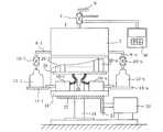
上述したような重量式多連充填機は、複数の物品充填装置を備え、これら物品充填装置によって同時並列に、順番にまたはランダムに容器に物品が充填される。このような充填機の一例である重量式液体充填機を、図4乃至図6に示す。この重量式液体充填機では、充填機本体1の上部側に設けられた貯槽2に、外部からユニバーサルジョイント4、パイプ6を介して被計量物品、例えば充填液が供給され、一時的に貯留されている。貯槽2の外周には、予め定めた角度ごとに充填用パイプ8−1乃至8−nが設けられている。これら充填用パイプ8−1乃至8−nの下端には、充填液の供給流量を制御するためのバルブ10−1乃至10−nが設けられている。これらバルブ10−1乃至10−nに付属するノズルから吐出する充填液の流量を、バルブ10−1乃至10−nが制御する。各バルブ10−1乃至10−nに対応して、容器、例えばボトル12が配置される複数の充填台14−1乃至14−nが、貯槽2の下方に相当する充填機本体1の下部外周に配置されている。これら充填台14−1乃至14−nは、これらにそれぞれ対応して設けられたロードセル16−1乃至16−nに結合されている。これらロードセル16−1乃至16−nは、充填機本体1の下方に配置されたロードセル載置台18上に設置されている。充填機本体1の貯槽2、ロードセル載置台18及び充填台14−1乃至14−nは、これの外部に設けた駆動手段、例えばモータ20、ギア21、22によって、充填機本体1の中心を上下方向に伸びる回転軸24の周囲に一定の速度で回転する。
【0003】
充填台14−1乃至14−nの回転に同期して、充填機の外部の搬送装置から、充填機の搬入位置(充填台14−1乃至14−nが回転して描く円周上の所定位置)に到達した空のボトル12−1乃至12−nが1個ずつ充填台14−1乃至14−n上に搬入され、ボトル12−1乃至12−nは回転しながら、重量測定され、その重量測定の結果に従って、充填液が一定量だけボトル12に充填される。充填が完了したボトル12−1乃至12−nは、搬出位置(充填台14−1乃至14−nが回転して描く円周上において搬入位置から離れた予め定めた位置)まで搬出され、充填機の次段に設けられた搬送装置に搬出される。
【0004】
バルブ10−1乃至10−nは、ボトル12−1乃至12−nの回転と共に回転し、バルブ10−1乃至10−nが回転して描く円周上の予め定められた位置に到達すると開かれる。その結果、充填液は予め定められた流量でボトル12−1乃至12−n内に充填され、ボトル12−1乃至12−n内の充填液の重量が、ボトル12−1乃至12−nに対応するロードセル16−1乃至16−nによって、測定される。ボトル12−1乃至12−n内の充填液の重量が目標充填重量より若干小さい第1レベルに到達すると、供給流量が小さくなるようにバルブ10−1乃至10−nの開度が制御される。ボトル12−1乃至12−n内の充填液の重量が、第1レベルよりも大きく、目標充填重量の直前の第2レベルに到達すると、バルブ10−1乃至10−nが閉じられる。バルブ10−1乃至10−nが閉じられた後、ボトル12−1乃至12−nに落差分が落ち込み、ボトル12−1乃至12−nには目標充填重量の充填液が充填される。
【0005】
各ボトル12−1乃至12−n内の充填液重量を測定するためには、各ロードセル16−1乃至16−nからのアナログ重量信号をA/D変換し、得られたデジタル重量信号に対して、充填機用秤演算を行う必要がある。そのため、各ロードセル16−1乃至16−nに対応して複数の充填秤機能演算手段、例えば演算ユニット26−1乃至26−nが設けられている。これら演算ユニット26−1乃至26−nは、充填台14−1乃至14−nと同数であり、貯槽2とロードセル16−1乃至16−nとの間に設けたユニット設置台28上に設けられ、対応するロードセル16−1乃至16−nに信号線28、28・・・によって接続されている。
【0006】
演算ユニット26−1乃至26−nで行われる演算は、次のようなものである。以下の説明では、1つの演算ユニットでの演算を説明するので、符号の添え字は省略する。ロードセル16に負荷される全ての物体、充填機の場合には充填台14とボトル12とを含む被計量物品の重量は、アナログ重量信号として出力され、アナログ重量信号がA/D変換され、デジタル重量信号Waとなる。充填機の重量測定システムを調整する時点で、予め充填台14上に物体が存在していないときのデジタル重量信号をイニシアル値Wiとして演算ユニット26内のメモリに記憶されている。充填台14上にボトル12が載置され、ボトル12に充填が開始されると、Waは増加する。充填台14上のボトル12と充填液との重量Wnは、Wn=K(Wa−Wi)に従って算出される。Kは、充填機の重量測定システムの調整時に充填台14に基準分銅を置いてWnが基準分銅の重量に等しくなるように調整、設定されるスパン係数である。スパン係数は、ロードセル16への負荷荷重、電圧変換率及び演算ユニット26で使用されるアナログ重量信号の増幅率によって決定される。即ち、ロードセル16によっても演算ユニット26によっても影響を受ける。
【0007】
ボトル12が充填台14上に無くとも、充填機の使用時に水滴などが充填台14に付着すると、Wnの値は零から変化する。そこで、零点の変動量をWzとし、Wn=K(Wa−Wi)−Wzを、充填台14上の物体の重量を表す式として、充填台14上にボトル12が存在しないときにWnが0でなければ、そのときのWnの値をWzに記憶させる。これは零点調整である。
【0008】
充填機は、最初に充填台14上に空のボトル12のみが搬入されるので、そのとき、Wnはボトル12の重量Wbを表す。そして、充填液がボトル12に充填される直前に、ボトル12の重量が測定され、風袋引きメモリに記憶される。液体の充填が開始されると、Wnはボトルと液体の重量を表すようになるので、Wn−Wbの演算を行って、液体のみの重量Wmを求める。または、ボトル12の重量分も含めて、零点調整が行われ、Wnを充填される液体の重量値のみを表わすようにする。この場合、Wn=Wmとなる。
【0009】
演算ユニット26には、液体の供給流量を制御するために、複数の重量レベルw1、w2、wtが設定されている。wtは目標充填重量、w2はwtにかなり近い値で、w1はw2よりも小さく設定されている。液体の充填開始時には、ノズル10から流量q1で充填される。液体の重量Wmは徐々に増加し、短い時間間隔で重量レベルw1と比較することが繰り返され、Wm>w1が成立するか否かがチェックされる。Wm>w1が成立すると、供給流量をq1からq2(q1>q2)に変更するように、対応するバルブ10に出力する。流量q2で充填が継続され、Wm>w2が成立するか短い時間間隔で検出して、Wm>w2が成立すると、充填液の供給を停止するように、対応するバルブ10に出力する。供給停止信号が出力されても、僅かに充填液はボトル12に供給されるので、ほぼWtに等しい重量分の充填液がボトル12に充填される。
【0010】
重量式の充填機では、最終的にボトル12に対して何グラムの液体が供給されたかを知るために、液体の供給停止後の一定時間経過後に、充填済みの液体の重量を改めて測定し、充填重量として出力する。
【0011】
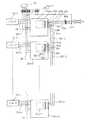
各演算ユニット26−1乃至26−nは、ロードセル設置台18、充填台14−1乃至14−nと共に回転するが、演算ユニット26−1乃至26−nへの電源は、ロータリジョイント4と回転軸を同じにして取り付けられているロータリコネクタによって外部から供給される。また、各演算ユニット26−1乃至26−nは、充填機本体1の外部に離れて設けられた表示・制御手段、例えば表示・制御装置30によって、各種制御を受け、各演算ユニット26−1乃至26−nから表示・制御装置30には、充填された液体の重量などのデータが伝送される。従って、各演算ユニット26−1乃至26−nと表示・制御装置30とが双方向の通信が行えるように、シリアル通信ラインで接続されている。シリアル通信に必要なラインの本数が増加すると、ロータリコネクタに接点が増加してロータリコネクタが高価になるので、演算ユニット26−1乃至26−nから出力される信号線は、端子台にて共通化され、最小2本のラインによって表示・制御装置30に伝送される。
【0012】
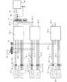
ロードセル16、各演算ユニット26−1乃至26−n、表示・制御装置30の接続状態を図5に示す。ロードセル16−1乃至16−nに付属する導線31−1乃至31−nは、アナログ重量信号線と電源線とからなる。端子台32−1乃至32−nは、導線31−1乃至31−nを、対応する演算ユニット26−1乃至26−nに接続するためのものである。配線33−1乃至33−nは、端子台32−1乃至32−nを演算ユニット26−1乃至26−nに接続するためのものである。各バルブ10−1乃至10−nの制御信号は、各演算ユニット26−1乃至26−nから与えられるので、バルブ10−1乃至10−nは、導線34−1乃至34−n、端子台32−1乃至32−n、導線35−1乃至35−nを介して対応する演算ユニット26−1乃至26−nに接続されている。
【0013】
また、各バルブ10−1乃至10−nが所定の充填開始位置に到達したときに液体の充填の制御を行うために、演算ユニット26−1乃至26−nは、バルブ10−1乃至10−nの回転位置を認識する必要がある。そこで、バルブ10−1乃至10−nの位置認識信号発信ユニット36が設けられている。位置認識信号は端子台38によって中継されると共に、端子台38上で共通化が行われ、各演算ユニット26−1乃至26−nへ、配線40−1乃至40−nによって供給されている。
【0014】
演算ユニット26−1乃至26−nから出力される通信線42−1乃至42−nは端子台44上で共通化が図られ、2本の信号線46でロータリコネクタ48を介して表示・制御装置30に接続されている。
【0015】
充填機が取り扱う被計量物品が液体であると、充填機を衛生的に保つために、洗浄がなされる。そのため、ロードセル16−1乃至16−nや演算ユニット26−1乃至26−nは、図6に示すように防水保護カバー50−1乃至50−n内に収容されるが、ロードセル16−1乃至16−nから伸びる支持金具52−1乃至52−nが保護カバー50−1乃至50−nから突出する出口には、ラビリンス54−1乃至54−nが設けられて、防水されている。
【0016】
【発明が解決しようとする課題】
上記のような重量式多連液体充填機では、狭いロードセル載置台18上に多くのロードセル16−1乃至16−nや演算ユニット26−1乃至26−nを搭載しなければならない。これらの部品配置のため、大きな空間が必要である。さらに、ロードセル16−1乃至16−nと、各演算ユニット26−1乃至26−nを別々に配置しているので、これらの間に、図5に示すように配線31−1乃至31−n、端子台32−1乃至32−n、配線33−1乃至33−nのように長い配線を、充填機の大きさに合わせて行わなければならず、配線作業のコストダウンの障害になっていた。
【0021】
本発明は、上記の問題点を解決した重量式多連充填機を提供することを目的とする。
【0022】
【課題を解決するための手段】
上述したような問題点の解決法として、複数の計量部と、これら計量部にそれぞれ対応して設けられた複数の充填制御バルブとを、備えた重量式多連充填機の前記各計量部にそれぞれ設けられる重量式多連充填機用ロードセルを、被計量物が載荷される起歪体と、 この起歪体に設けられ、前記被計量物の重量を表すアナログ重量信号を生成する重量検出手段と、前記起歪体の固定部に形成され開口面を金属蓋で溶接されて空洞である密閉容器または前記起歪体の表面に設けられた密閉容器と、この容器内に設けられ、前記アナログ重量信号をA/D変換し、前記被計量物の重量レベルを判定する秤機能演算手段とを、備え、前記秤機能演算手段は、対応する前記充填制御バルブに制御信号を供給するように構成され、前記秤機能演算手段は、表示用及び設定用の1組のシリアル信号が入出力される端子を備えるように構成するものがある。
【0023】
更に、ロードセルがそれぞれに設けられた前記複数の計量部と、前記複数の充填制御バルブと、前記各ロードセルに対して共通に設けられた1台の表示及び制御装置とを、具備し、前記各ロードセルの前記各秤機能演算手段から、これらが設けられた前記各ロードセルが設けられている前記計量部に対応する前記各充填制御バルブに、直接に前記制御信号を供給する信号ラインがそれぞれ配線され、前記各ロードセルの前記各秤機能演算手段が備える前記端子は、前記シリアル信号を前記各秤機能演算手段内部を介して入出力する前段側端子と後段側端子とからなり、前記各秤機能演算手段は、初段のものから最終段のものまで、前段にあるものの前記後段側端子が後段側にあるものの前記前段側端子に接続され、前記初段のものの前記前段側端子が前記表示及び制御装置に接続されることによって、表示用及び制御用の1組のシリアル信号ラインが配線されている重量式多連充填機を構成する。
【0037】
【発明の実施の形態】
本発明の1実施の形態の重量式多連液体充填機を、図1乃至図3に示す。この充填機1aは、図4と図2との対比から明らかなように充填秤機能演算ユニット26−1乃至26−n及びロードセル16−1乃至16−nに代えて、演算ユニット付きロードセル16a−1乃至16a−nが設けられている。なお、他の同等部分には、同一符号を付して、その説明を省略する。
【0038】
これら演算ユニット付きロードセル16a−1乃至16a−nでは、図3(b)に符号81で示すように、起歪体の固定部に空洞を形成し、その空洞内に小型化した演算ユニット26a−1乃至26a−nが内蔵されている。このロードセルの起歪体において、荷重検出部は、円筒加工部82であり、荷重の負荷によって円筒加工部82はだ円形に歪む、円筒加工部82の内面にストレインゲージ83、84、85、86を貼付し、歪量が検出される。円筒加工部82の内面の表面を被うように円筒状の保護カバー87が溶接され、これらストレインゲージ83、84、85、86は、外気から密閉保護される。ストレインゲージ83、84、85、86と演算ユニット26a−1乃至26a−n間の配線は、起歪体内部に形成された連結孔88によって行われる。この演算ユニット26a−1乃至26a−nの機能は、従来の演算ユニット26−1乃至26−nと同一である。これら空洞の開口面には、金属蓋80が溶接されて、防水密閉構造とされている。従来のもののように別個に演算ユニット26−1乃至26−nを設ける必要がなく、これら演算ユニット26−1乃至26−nやストレインゲージ83、84、85、86に対する防水対策も不要となり、ラビリンスを設ける必要もない。さらに、各ロードセル16a−1乃至16a−nから、対応する演算ユニット26a−1乃至26a−nへの配線も省略できる。なお、図3(c)は図3(b)のロードセルにおいて、演算ユニット26−1乃至26−nを起歪体内部に収納せずに、別途、密閉容器89を起歪体表面上に設け、その中に収納した例である。
【0039】
図1に、この充填機1aにおける配線状態を示す。演算ユニット付きロードセル16a−1乃至16n−1は、従来のロードセル16−1乃至16−nと演算ユニット26−1乃至26−nとの機能を併せて含むものであるので、従来のロードセル16−1乃至16−nと演算ユニット26−1乃至26−nとを接続していた配線33−1乃至33−nが省略されている。
【0040】
演算ユニット付きロードセル16a−1乃至16a−nの演算ユニット26a−1乃至26a−nの2箇所に、共通信号が入出力する端子81a、81b、81c、82a、82b、82cが設けられ、これら端子81a、81b、81c、82a、82b、82cから出力コネクタ83a、83b、83c、84a、84b、84cにそれぞれ信号が出力するように配線されている。
【0041】
回転式またはライン式の重量式多連充填機では、各ロードセル16a−1乃至16a−nは、等角度に配置されているので、予め同じ長さの配線ユニット85−1乃至85−nを製作し、隣接するロードセル同士の出力コネクタ83a、83b、83c、84a、84b、84cを接続してある。これによって、充填機本体1a上での配線作業時間を短縮することができる。
【0042】
また、各ロードセル16a−1乃至16a−nの各演算ユニット26a−1乃至26a−nへ、外部に設置した表示・制御装置30から与える零点調整、風袋量記憶、スパン調整等の命令は、全て予め定められ、且つユーザーに公開されたコード信号によって与えられる。従って、表示・制御装置30において設計者の自由な裁量によって、操作手順、キースイッチの適用が可能になる。例えば或る画面上に表現したソフトウエアスイッチによって所定の命令コードを発生させるようにして、ロードセル16a−1乃至16a−nの演算ユニット26a−1乃至26a−nに命令を実行させる。
【0043】
演算ユニット26a−1乃至26a−nは、これらが生成する充填動作完了後の安定時点における充填計量値や、スパン調整時に決定されたスパン係数等の諸データに、予め定められ、ユーザーに公開されている識別コード信号を付して出力している。従って、表示・制御装置30は、それら諸データに付されている識別コードの内容を判定して、適切な字体や形状(場合によってはグラフィックに)を適切な画面の適切な位置に表示できる。
【0044】
各ロードセル16a−1乃至16a−nには、各演算ユニット26a−1乃至26a−nが内蔵されているので、表示・制御装置30において供給流量制御、供給停止のためのレベル設定値、従来の技術で述べたw1、w2、wtを予め定めたコード信号付きで設定されるようにしておくと、各演算ユニット26a−1乃至26a−nの所定のメモリに自動的にそれらが伝送されて、設定データとなる。
【0045】
各演算ユニット26a−1乃至26a−nは、各ロードセル16a−1乃至16a−nのアナログ計量信号を短い時間間隔でサンプリングし、所定の計量値演算によってボトル12−1乃至12−nに充填される充填液の重量の算出、この重量が所定値に到達したかどうかのレベル判定を実行し、所定値に到達すれば、直ちにバルブを制御して、供給流量を調整している。それぞれのボトルに短い時間間隔で、充填秤機能演算され、対応したバルブに所定の制御信号を出力するので、時間遅れを生じない。従って、各演算ユニット26a−1乃至26a−nを備えた各ロードセル16a−1乃至16a−nは、被計量物品の充填精度に悪影響を及ぼさない。
【0046】
各ロードセル16a−1乃至16a−nに設置した各演算ユニット26a−1乃至26a−nによって、充填供給流量を制御しているので、各演算ユニット26a−1乃至26a−nを備えた各ロードセル16a−1乃至16a−nは、充填台14−1乃至14−nに対応している各バルブ10−1乃至10−nに制御信号を直接に出力している。従って、制御信号伝送用の線路34−1乃至34−nの配線を直接にバルブ10−1乃至10−nに供給でき、配線を引き回す必要がなく、スペース、作業時間時間の面で効率化される。
【0055】
上記の実施の形態では、本発明を液体充填機に実施したが、これに限ったものではなく、被計量物品は液体以外に、粉体や粒体を使用することもできる。また、上記の実施の形態では、ロードセルや容器が回転する回転型の充填機を使用したが、被計量物品が充填されながら、直線状に移動するライン式の充填機を使用することもできる。
【図面の簡単な説明】
【図1】 本発明の1実施形態の重量式多連液体充填機のブロック図である。
【図2】 図1の重量式多連液体充填機の部分省略側面図である。
【図3】 図1の重量式多連液体充填機に使用するロードセルの全体図及び拡大図並びにロードセルの他の例の平面図である。
【図4】従来の重量式多連液体充填機の側面図である。
【図5】図4の重量式多連液体充填機のブロック図である。
【図6】図4の重量式多連液体充填機で使用するロードセルの拡大図である。
【符号の説明】
16−1乃至16−n ロードセル
26−1乃至26−n 演算ユニット(充填秤機能演算手段)
30 表示・制御装置
90 密閉容器
100、100a、100b 上位演算ユニット(上位演算手段)[0001]
BACKGROUND OF THE INVENTION
The present invention relates to a weight-type multiple filling machine that fills a container such as a bag, a bottle or a box with a predetermined weight, for example, an object to be weighed such as a liquid, a powder, and a granule, and in particular, its weight. It relates to a measurement system.
[0002]
[Prior art]
The above-described heavy-duty multiple filling machine includes a plurality of article filling apparatuses, and the articles are filled into the container simultaneously or in parallel by these article filling apparatuses. A weight type liquid filling machine as an example of such a filling machine is shown inFIGS . In this weight type liquid filling machine, an article to be weighed, for example, a filling liquid is supplied to the
[0003]
In synchronism with the rotation of the filling tables 14-1 to 14-n, from the conveying device outside the filling machine, the loading position of the filling machine (predetermined on the circumference drawn by the rotation of the filling tables 14-1 to 14-n). Empty bottles 12-1 to 12-n that have reached position) are carried one by one onto the filling tables 14-1 to 14-n, and the bottles 12-1 to 12-n are weighed while rotating, According to the result of the weight measurement, the
[0004]
The valves 10-1 to 10-n rotate with the rotation of the bottles 12-1 to 12-n and open when the valves 10-1 to 10-n rotate and reach a predetermined position on the circumference drawn. It is. As a result, the filling liquid is filled into the bottles 12-1 to 12-n at a predetermined flow rate, and the weight of the filling liquid in the bottles 12-1 to 12-n is reduced to the bottles 12-1 to 12-n. Measured by corresponding load cells 16-1 to 16-n. When the weight of the filling liquid in the bottles 12-1 to 12-n reaches the first level that is slightly smaller than the target filling weight, the opening degree of the valves 10-1 to 10-n is controlled so that the supply flow rate becomes small. . When the weight of the filling liquid in the bottles 12-1 to 12-n is larger than the first level and reaches the second level immediately before the target filling weight, the valves 10-1 to 10-n are closed. After the valves 10-1 to 10-n are closed, the drop difference falls in the bottles 12-1 to 12-n, and the bottles 12-1 to 12-n are filled with the filling liquid of the target filling weight.
[0005]
In order to measure the weight of the filling liquid in each of the bottles 12-1 to 12-n, the analog weight signals from the load cells 16-1 to 16-n are A / D converted, and the obtained digital weight signals are Therefore, it is necessary to perform a weighing operation for the filling machine. Therefore, a plurality of filling scale function calculation means, for example, calculation units 26-1 to 26-n are provided corresponding to the load cells 16-1 to 16-n. These arithmetic units 26-1 to 26-n are the same in number as the filling tables 14-1 to 14-n, and are provided on the unit installation table 28 provided between the
[0006]
The calculations performed by the calculation units 26-1 to 26-n are as follows. In the following description, calculation in one calculation unit will be described, and thus the suffix of the reference numerals will be omitted. The weight of all objectsloaded on the
[0007]
Even if the
[0008]
In the filling machine, only the
[0009]
A plurality of weight levels w1, w2, and wt are set in the
[0010]
In the weight-type filling machine, in order to know how many grams of liquid has finally been supplied to the
[0011]
Each of the arithmetic units 26-1 to 26-n rotates together with the load
[0012]
FIG. 5 shows the connection state of the
[0013]
In addition, in order to control the filling of the liquid when each of the valves 10-1 to 10-n reaches a predetermined filling start position, the arithmetic units 26-1 to 26-n include the valves 10-1 to 10-n. It is necessary to recognize the rotational position of n. Therefore, a position recognition
[0014]
The communication lines 42-1 to 42-n output from the arithmetic units 26-1 to 26-n are made common on the
[0015]
If the article to be weighed handled by the filling machine is liquid, washing is performed to keep the filling machine hygienic. Therefore, the load cells 16-1 to 16-n and the arithmetic units 26-1 to 26-n are accommodated in the waterproof protection covers 50-1 to 50-n as shown inFIG. Labyrinths 54-1 to 54-n are provided at the outlets where the support fittings 52-1 to 52-n extending from 16-n protrude from the protective covers 50-1 to 50-n, and are waterproofed.
[0016]
[Problems to be solved by the invention]
In the above-described heavy-duty multiple liquid filling machine, many load cells 16-1 to 16-n and arithmetic units 26-1 to 26-n must be mounted on a narrow load cell mounting table 18. A large space is required for the arrangement of these parts. Further, since the load cells 16-1 to 16-n and the arithmetic units 26-1 to 26-n are separately arranged, the wirings 31-1 to 31-n are interposed between them asshown in FIG. , Long wires such as the terminal blocks 32-1 to 32-n and the wires 33-1 to 33-n have to be made according to the size of the filling machine, which is an obstacle to the cost reduction of the wiring work. It was.
[0021]
An object of the present invention is to provide a weight-type multiple filling machine that solves the aboveproblems .
[0022]
[Means for Solving the Problems]
As a solution to the above-described problems, each weighing unit of the weight-type multiple filling machine provided with a plurality of weighing units and a plurality of filling control valves provided respectively corresponding to these weighing units is provided. Weight type multiple filling machine load cells provided respectively, a strain generating body on which an object to be weighed is loaded, and a weight detection means which is provided on the strain generating body and generates an analog weight signal indicating the weight of the object to be weighed A sealed container formed in the fixed part of the strain generating body and having an opening surface welded with a metal lid, or a sealed container provided on the surface of the strain generating body, and the analog provided in the container. Weighing function calculation means for A / D converting the weight signal and determining the weight level of the object to be weighed, and the weighing function calculation means is configured to supply a control signal to the corresponding filling control valve The scale function calculation means is Some are configured to have a terminal for inputting and outputting a set of serial signals for display and setting.
[0023]
And a plurality of metering units each provided with a load cell, a plurality of filling control valves, and a single display and control device provided in common for each load cell. A signal line for supplying the control signal directly is wired from each weighing function calculation means of the load cell to each filling control valve corresponding to the weighing unit in which the load cell is provided. The terminals included in the scale function calculation means of the load cells include a front-stage terminal and a rear-stage side terminal for inputting and outputting the serial signal through the scale function calculation means. The means is from the first stage to the last stage, but the rear stage side terminal is connected to the front stage side terminal of the first stage, although the rear stage side terminal is on the rear stage side. By terminal is connected to the display and control unit, constitutinga gravimetric multiple-filling machine set of the serial signal line for display and control are wired.
[0037]
DETAILED DESCRIPTION OF THE INVENTION
1 gravimetric embodiment multiple-liquid filling machine of the present invention, shown in FIGS. As apparent from the comparison between FIG. 4 and FIG. 2, the filling machine 1a replaces the filling scale function computing units 26-1 to 26-n and the load cells 16-1 to 16-n with a
[0038]
In these load cells with
[0039]
In FIG. 1, the wiring state in this filling machine 1a is shown. Since the
[0040]
[0041]
In the rotary type or line type heavy weight multiple filling machine, the
[0042]
In addition, all the instructions such as zero adjustment, tare amount storage, span adjustment, etc. given from the external display /
[0043]
The
[0044]
Since each of the
[0045]
Each
[0046]
Since the charging and supplying flow rate is controlled by the
[0055]
In the above embodiment, the present invention is implemented in the liquid filling machine, but the present invention is not limited to this, and the object to be weighed can also use powder or granules in addition to the liquid. In the above embodiment, a rotary filling machine in which a load cell and a container rotate is used. However, a line type filling machine that moves linearly while an article to be weighed is filled can also be used.
[Brief description of the drawings]
1 is a block diagram of a gravimetric multiple-liquid filling machine ofone embodiment of the present invention.
FIG. 2 is a partially omitted side view of the weight-type multiple liquid filling machine of FIG.
3 is an overall view and an enlarged view of a load cell used in the heavy-duty multiple liquid filling machine of FIG. 1, and a plan view of another example of the load cell. FIG.
FIG. 4is a side view of a conventional heavy-duty multiple liquid filling machine.
FIG. 5is a block diagram of the weight type multiple liquid filling machine of FIG. 4;
6is an enlarged view of a load cell used in the weight-type multiple liquid filling machine of FIG.
[Explanation of symbols]
16-1 thru | or 16-n load cell 26-1 thru | or 26-n arithmetic unit (filling scale function calculating means)
30 Display / Control Device 90 Sealed Container 100, 100a, 100b Upper Arithmetic Unit (Upper Arithmetic Means)
Claims (2)
Translated fromJapanese被計量物が載荷される起歪体と、
この起歪体に設けられ、前記被計量物の重量を表すアナログ重量信号を生成する重量検出手段と、
前記起歪体の固定部に形成され開口面を金属蓋で溶接された空洞である密閉容器または前記起歪体の表面に設けられた密閉容器と、
この容器内に設けられ、前記アナログ重量信号をA/D変換し、前記被計量物の重量レベルを判定する秤機能演算手段とを、
備え、前記秤機能演算手段は、対応する前記充填制御バルブに制御信号を直接に供給するように構成され、前記秤機能演算手段は、表示用及び設定用の1組のシリアル信号が入出力される端子を備える重量式多連充填機用ロードセル。A load cell for a weight type multiple filling machineprovided in each of the weighing parts of the weight type multiple filling machine provided with a plurality of weighing parts and a plurality of filling control valves provided respectively corresponding to these weighing parts. Because
A strain body on which an object to be weighed is loaded;
Weight detecting means provided on the strain body for generating an analog weight signal representing the weight of the object to be weighed,
A sealed container which is a cavity formed in a fixed portion of the strain body and whose opening surface is welded with a metal lid, or a sealed container provided on the surface of the strain body;
A scale function calculating means provided in the container, A / D-converting the analog weight signal and determining a weight level of the object to be weighed;
Thescale function calculating means is configured to directly supply a control signal to the corresponding filling control valve, and the scale function calculating means receives and outputs a set of serial signals for display and setting. Load cell for heavy-duty multiple filling machines equipped with terminals.
前記複数の充填制御バルブと、
前記各ロードセルに対して共通に設けられた1台の表示及び制御装置とを、
具備し、前記各ロードセルの前記各秤機能演算手段から、これらが設けられた前記各ロードセルが設けられている前記計量部に対応する前記各充填制御バルブに、直接に前記制御信号を供給する信号ラインがそれぞれ配線され、
前記各ロードセルの前記各秤機能演算手段が備える前記端子は、前記シリアル信号を前記各秤機能演算手段内部を介して入出力する前段側端子と後段側端子とからなり、前記各秤機能演算手段は、初段のものから最終段のものまで、前段にあるものの前記後段側端子が後段側にあるものの前記前段側端子に接続され、前記初段のものの前記前段側端子が前記表示及び制御装置に接続されることによって、表示用及び制御用の1組のシリアル信号ラインが配線されている重量式多連充填機。The plurality of weighing units each provided with the load cell for a weight type multiple filling machine according to claim 1,
The plurality of filling control valves;
One display and control device provided in common for each of the load cells,
A signal for supplying the control signal directly from the scale function calculation means of the load cells to the filling control valves corresponding to the metering units provided with the load cells provided with the load cell. Each line is wired
Each terminal provided in each scale function computing means of each load cell comprises a front stage side terminal and a rear stage side terminal for inputting and outputting the serial signal via each scale function computing means, and each scale function computing means From the first stage to the last stage, the rear stage side terminal is connected to the front stage side terminal of the first stage, but the front stage side terminal of the first stage is connected to the display and control device As a result, a weight type multiple filling machinein which a set of serial signal lines for display and control is wired .
Priority Applications (9)
| Application Number | Priority Date | Filing Date | Title |
|---|---|---|---|
| JP2001259719AJP4955163B2 (en) | 2001-08-29 | 2001-08-29 | Heavy duty multiple filling machine |
| US10/131,705US6655421B2 (en) | 2001-08-29 | 2002-04-24 | Weight-based, multiple filler filling machine |
| DE60226551TDE60226551D1 (en) | 2001-08-29 | 2002-04-25 | Filling machine with several weight-controlled filling units |
| EP02252952AEP1288125B1 (en) | 2001-08-29 | 2002-04-25 | Weight-based, multiple filler filling machine |
| EP07013249AEP1847459B1 (en) | 2001-08-29 | 2002-04-25 | Weight-based, multiple filler filling machine |
| DE60234139TDE60234139D1 (en) | 2001-08-29 | 2002-04-25 | Weight-based filling machine with multiple filling units |
| KR10-2002-0034393AKR100460596B1 (en) | 2001-08-29 | 2002-06-19 | Weight-based, multiple-filler filling machine |
| TW091115112ATW577979B (en) | 2001-08-29 | 2002-07-09 | Weight-based, multiple-filler filling machine |
| CNB021277990ACN1234567C (en) | 2001-08-29 | 2002-08-09 | Multi-filling opening filling machine based on weight |
Applications Claiming Priority (1)
| Application Number | Priority Date | Filing Date | Title |
|---|---|---|---|
| JP2001259719AJP4955163B2 (en) | 2001-08-29 | 2001-08-29 | Heavy duty multiple filling machine |
Publications (2)
| Publication Number | Publication Date |
|---|---|
| JP2003072701A JP2003072701A (en) | 2003-03-12 |
| JP4955163B2true JP4955163B2 (en) | 2012-06-20 |
Family
ID=19087045
Family Applications (1)
| Application Number | Title | Priority Date | Filing Date |
|---|---|---|---|
| JP2001259719AExpired - LifetimeJP4955163B2 (en) | 2001-08-29 | 2001-08-29 | Heavy duty multiple filling machine |
Country Status (7)
| Country | Link |
|---|---|
| US (1) | US6655421B2 (en) |
| EP (2) | EP1288125B1 (en) |
| JP (1) | JP4955163B2 (en) |
| KR (1) | KR100460596B1 (en) |
| CN (1) | CN1234567C (en) |
| DE (2) | DE60226551D1 (en) |
| TW (1) | TW577979B (en) |
Families Citing this family (47)
| Publication number | Priority date | Publication date | Assignee | Title |
|---|---|---|---|---|
| JP4207543B2 (en)* | 2002-11-21 | 2009-01-14 | 澁谷工業株式会社 | Rotary weight filling machine |
| JP2004276962A (en)* | 2003-03-14 | 2004-10-07 | Ricoh Co Ltd | Apparatus and method for filling powder |
| US20060157152A1 (en)* | 2004-08-13 | 2006-07-20 | Wolski Peter F | Beverage dispenser with game controller |
| US7069964B1 (en)* | 2005-03-03 | 2006-07-04 | Shibuya Kogyo Co., Ltd. | Filler |
| JP2006280916A (en)* | 2005-03-11 | 2006-10-19 | Yuyama Manufacturing Co Ltd | Medicine-weighing apparatus |
| FR2888321B1 (en)* | 2005-07-06 | 2007-10-05 | Serac Group Soc Par Actions Si | PONDERAL FILLING SYSTEM OF CONTAINERS WITH ENGAGEMENT OF THE FILLING FILLERS IN THE CONTAINERS |
| US20070107801A1 (en)* | 2005-11-14 | 2007-05-17 | Sidel And Pressco Technology Inc. | Bottle filling machine with sensor and method thereof |
| US20070151621A1 (en)* | 2006-01-05 | 2007-07-05 | Honeywell International Inc. | Automatic shutoff and metering device |
| US20120292367A1 (en) | 2006-01-31 | 2012-11-22 | Ethicon Endo-Surgery, Inc. | Robotically-controlled end effector |
| DE102006039090A1 (en)* | 2006-08-19 | 2008-02-21 | Khs Ag | Drive for rotary machines |
| NZ576265A (en)* | 2006-09-26 | 2011-10-28 | Big Bottle Ip Pty Ltd | Dispensing apparatus and weighing process with control unit |
| ITBO20070549A1 (en)* | 2007-08-02 | 2009-02-03 | Acma Spa | SUPPORT AND WEIGHING FOR CONTAINERS. |
| US9851240B2 (en)* | 2008-03-06 | 2017-12-26 | Nicole Sollazzo Lee | Precision measurement dispenser |
| EP2124025B1 (en)* | 2008-05-22 | 2012-12-26 | Mettler-Toledo AG | Method and device for filling target containers |
| FR2946623B1 (en)* | 2009-06-11 | 2016-07-01 | Serac Group | SUSPENDED DELIVERY DEVICE AND FILLING PLANT FOR CONTAINERS COMPRISING SUCH DEVICES. |
| DE102009032794A1 (en)* | 2009-07-10 | 2011-01-13 | Krones Ag | Device for filling containers with multicomponent liquids |
| GB201108479D0 (en)* | 2011-05-20 | 2011-07-06 | Mount Packaging Systems Ltd | Filling containers with a flowable medium |
| DE102011119451A1 (en)* | 2011-11-28 | 2013-05-29 | Haver & Boecker Ohg | Packing machine and method for filling sacks |
| US9245061B2 (en) | 2012-04-25 | 2016-01-26 | Shapeways, Inc. | Weight-based identification of three dimensional printed parts |
| EP2803621A1 (en)* | 2013-05-15 | 2014-11-19 | Sidel S.p.a. Con Socio Unico | Filling unit of a container filling machine, having improved sensing capability |
| CN103407594A (en)* | 2013-07-31 | 2013-11-27 | 安徽兴隆肥业科技有限责任公司 | Automatic packaging machine for chemical fertilizer production |
| CN103407593A (en)* | 2013-07-31 | 2013-11-27 | 安徽兴隆肥业科技有限责任公司 | Packing machine for chemical fertilizer manufacturing |
| CN103407627A (en)* | 2013-07-31 | 2013-11-27 | 安徽兴隆肥业科技有限责任公司 | Automatic packing machine for chemical fertilizer manufacturing |
| DE102014107364A1 (en)* | 2014-05-26 | 2015-11-26 | Endress+Hauser Process Solutions Ag | Method for valve-controlled filling |
| CN104058142B (en)* | 2014-06-17 | 2016-06-29 | 广州丽盈塑料有限公司 | A kind of filling apparatus possessing Quick Changeover function |
| CN104150422A (en)* | 2014-08-27 | 2014-11-19 | 梧州市旺捷机械制造有限公司 | Automatic measuring liquid filling machine |
| US9845167B1 (en)* | 2016-09-01 | 2017-12-19 | Multiply Labs Inc. | Dispensing system |
| US11040491B2 (en) | 2016-10-19 | 2021-06-22 | Shapeways, Inc. | Systems and methods for identifying three-dimensional printed objects |
| USD823454S1 (en) | 2017-02-23 | 2018-07-17 | Fisher & Paykel Healthcare Limited | Cushion assembly for breathing mask assembly |
| US10946990B2 (en)* | 2017-07-31 | 2021-03-16 | Alpha Brewing Operations | Material saving canning system |
| EP3527960B1 (en)* | 2018-02-14 | 2022-01-19 | MG Colors GmbH | Paint dispensing method |
| WO2019222540A1 (en)* | 2018-05-18 | 2019-11-21 | Medway Plastics Corporation | Cover for a region of a mobile phone |
| IT201800006114A1 (en)* | 2018-06-07 | 2019-12-07 | METHOD FOR HANDLING AND CONTROL OF PRODUCTS OR RAW MATERIAL IN BLOCKS OR SHEETS | |
| TWI690462B (en)* | 2018-12-14 | 2020-04-11 | 林淑玲 | Liquid discharging machine |
| US11981463B2 (en)* | 2019-05-22 | 2024-05-14 | I.M.A. Industrial Macchine Automatiche S.P.A. | Dosing device for feeding an infusion product |
| CN110467142B (en)* | 2019-09-10 | 2024-12-31 | 楚天科技股份有限公司 | Filling method and filling system |
| CN110759299B (en)* | 2019-11-20 | 2024-02-27 | 广东科谷实验室技术研究院(有限合伙) | Forced interaction singlechip system and working method thereof |
| US11535409B1 (en)* | 2019-12-18 | 2022-12-27 | Richard James DeMartini | Personal liquid cannabis 6D oil printer and smart cartridges |
| CN112093095B (en)* | 2020-09-14 | 2021-12-21 | 山东翠宝新型材料科技有限公司 | A kind of paint glass fiber reinforced plastic mixing tank that can be filled quantitatively |
| CN113526442B (en)* | 2021-08-19 | 2025-08-12 | 广州达意隆包装机械股份有限公司 | Filling system and filling method |
| JP2023117146A (en)* | 2022-02-10 | 2023-08-23 | 株式会社京都製作所 | POWDER FILLING METHOD AND POWDER FILLING APPARATUS |
| CN114735253B (en)* | 2022-02-28 | 2024-11-12 | 唐山图灵科技股份有限公司 | Cement bag weighing equipment and bag weight data transmission method |
| CN115402546A (en)* | 2022-09-22 | 2022-11-29 | 萨克新材料科技(山东)有限公司 | Environment-friendly and long-service-life lubricating oil and processing system |
| CN116281806A (en)* | 2023-03-15 | 2023-06-23 | 广州黑格智造信息科技有限公司 | Resin filling method, resin filling device, computer readable storage medium and electronic equipment |
| CN116374327B (en)* | 2023-06-06 | 2023-08-01 | 江苏良友正大股份有限公司 | Automatic pellet feed equipment for packing and unloading |
| WO2025000109A1 (en) | 2023-06-28 | 2025-01-02 | Volumina Medical Sa | Method for successive, pressure-driven dispensation of single doses of a multiphasic mixture with controlled concentration and dose from a larger reservoir to smaller recipients and apparatus for performing the method |
| CN117465741B (en)* | 2023-12-28 | 2024-04-02 | 湖南九华石油科技有限公司 | Quantitative filling device is used in lubricating oil production and processing |
Family Cites Families (17)
| Publication number | Priority date | Publication date | Assignee | Title |
|---|---|---|---|---|
| CH514912A (en)* | 1970-10-09 | 1971-10-31 | Starkstrom Anlagenbau Veb K | Circuit for storing binary pulses, especially for programmed control systems |
| DK153679C (en)* | 1981-11-30 | 1988-12-27 | Smidth & Co As F L | PROCEDURE FOR FILLING POWDER-SHAPED MATERIAL IN VALVE BAGS AND MACHINE FOR EXERCISING THE PROCEDURE |
| JPS6078798U (en)* | 1983-11-04 | 1985-06-01 | 株式会社ほくさん | Rotary liquid filling device |
| US4582102A (en) | 1984-08-27 | 1986-04-15 | Risser James A | Means for electronically comparing the extent of fill in containers with a preset extent |
| JPS61182528A (en) | 1985-02-08 | 1986-08-15 | Kubota Ltd | Pressure-resistant and explosion-proof quantitative filling device |
| JP2574253B2 (en)* | 1986-08-22 | 1997-01-22 | 株式会社テック | Load cell |
| US4815547A (en) | 1987-11-30 | 1989-03-28 | Toledo Scale Corporation | Load cell |
| JPH01148828U (en)* | 1988-04-01 | 1989-10-16 | ||
| JPH01291120A (en) | 1988-05-17 | 1989-11-22 | Harada Sangyo Kk | Weighing mechanism for fermented soybeam filling device |
| GB2221039A (en) | 1988-07-05 | 1990-01-24 | Peter Adam Reuter | Load cell device with integral data processing/output means |
| JP2518966B2 (en)* | 1990-11-28 | 1996-07-31 | 株式会社テック | Electronic scales |
| JP3072029B2 (en)* | 1994-07-04 | 2000-07-31 | 東芝テック株式会社 | Load cell unit |
| US5700982A (en)* | 1995-01-23 | 1997-12-23 | Tedea-Huntleigh International, Ltd. | Symmetrical load cells for use in conjunction with rotary machines |
| IT1273488B (en)* | 1995-02-02 | 1997-07-08 | Gen Detergents Spa | AUTOMATIC FILLER TO RE-FILL BOTTLES AND SIMILAR |
| JP3823234B2 (en)* | 1996-12-17 | 2006-09-20 | 大和製衡株式会社 | Load cell |
| US6639156B2 (en)* | 1999-12-30 | 2003-10-28 | Tom J. Luke | Method and device for monitoring inventory |
| JP4766771B2 (en)* | 2001-04-26 | 2011-09-07 | 大和製衡株式会社 | Load cell |
- 2001
- 2001-08-29JPJP2001259719Apatent/JP4955163B2/ennot_activeExpired - Lifetime
- 2002
- 2002-04-24USUS10/131,705patent/US6655421B2/ennot_activeExpired - Fee Related
- 2002-04-25EPEP02252952Apatent/EP1288125B1/ennot_activeExpired - Lifetime
- 2002-04-25DEDE60226551Tpatent/DE60226551D1/ennot_activeExpired - Lifetime
- 2002-04-25DEDE60234139Tpatent/DE60234139D1/ennot_activeExpired - Lifetime
- 2002-04-25EPEP07013249Apatent/EP1847459B1/ennot_activeExpired - Lifetime
- 2002-06-19KRKR10-2002-0034393Apatent/KR100460596B1/ennot_activeExpired - Lifetime
- 2002-07-09TWTW091115112Apatent/TW577979B/ennot_activeIP Right Cessation
- 2002-08-09CNCNB021277990Apatent/CN1234567C/ennot_activeExpired - Lifetime
Also Published As
| Publication number | Publication date |
|---|---|
| DE60234139D1 (en) | 2009-12-03 |
| US20030041916A1 (en) | 2003-03-06 |
| JP2003072701A (en) | 2003-03-12 |
| DE60226551D1 (en) | 2008-06-26 |
| EP1847459B1 (en) | 2009-10-21 |
| CN1234567C (en) | 2006-01-04 |
| TW577979B (en) | 2004-03-01 |
| EP1288125A1 (en) | 2003-03-05 |
| EP1847459A1 (en) | 2007-10-24 |
| KR20030019086A (en) | 2003-03-06 |
| EP1288125B1 (en) | 2008-05-14 |
| US6655421B2 (en) | 2003-12-02 |
| KR100460596B1 (en) | 2004-12-09 |
| CN1403343A (en) | 2003-03-19 |
Similar Documents
| Publication | Publication Date | Title |
|---|---|---|
| JP4955163B2 (en) | Heavy duty multiple filling machine | |
| CA2469267A1 (en) | Method and apparatus for gravimetric dosing bulk material | |
| US6776199B2 (en) | Container filling machine | |
| KR870006393A (en) | Combination Weigher | |
| CN112229489A (en) | Data correction method for load sensor | |
| CN114715451B (en) | Automatic weighing metering device for grain storage bin | |
| JP4744364B2 (en) | Multiple weight sorter | |
| JP5424922B2 (en) | Filling equipment | |
| CN113148593A (en) | Automatic control system and method for port bulk cargo unloading hopper flow | |
| JP2002071434A (en) | Scale with container and signal processing method | |
| JP2002243562A (en) | Digital load cell and multi load cell scales | |
| NL8402367A (en) | WEIGHING EQUIPMENT. | |
| US20220205832A1 (en) | An enhanced weight calculating utensil | |
| JP3406657B2 (en) | Combination weighing method and apparatus | |
| US5029658A (en) | Mass/weight measurement filtering system | |
| JPH0729468Y2 (en) | Combination scale | |
| CN208038288U (en) | Material control device | |
| CN203497486U (en) | Intelligent liquid tank car volume metering device | |
| JP2549082B2 (en) | Weighing system | |
| CN107356030A (en) | Automatic refrigerant filling device and method | |
| CN111731526A (en) | Automatic packaging device for granular or powdery articles | |
| SU1580179A1 (en) | Apparatus for measuring and accounting the amount of material for weigher of cyclic action | |
| JPH0348451B2 (en) | ||
| JPH0136045B2 (en) | ||
| JP2003149037A (en) | Combination weighing apparatus |
Legal Events
| Date | Code | Title | Description |
|---|---|---|---|
| A621 | Written request for application examination | Free format text:JAPANESE INTERMEDIATE CODE: A621 Effective date:20080807 | |
| A977 | Report on retrieval | Free format text:JAPANESE INTERMEDIATE CODE: A971007 Effective date:20100914 | |
| A131 | Notification of reasons for refusal | Free format text:JAPANESE INTERMEDIATE CODE: A131 Effective date:20101005 | |
| A521 | Written amendment | Free format text:JAPANESE INTERMEDIATE CODE: A523 Effective date:20101206 | |
| A02 | Decision of refusal | Free format text:JAPANESE INTERMEDIATE CODE: A02 Effective date:20110705 | |
| A521 | Written amendment | Free format text:JAPANESE INTERMEDIATE CODE: A523 Effective date:20111004 | |
| A911 | Transfer to examiner for re-examination before appeal (zenchi) | Free format text:JAPANESE INTERMEDIATE CODE: A911 Effective date:20111014 | |
| A131 | Notification of reasons for refusal | Free format text:JAPANESE INTERMEDIATE CODE: A131 Effective date:20111220 | |
| A521 | Written amendment | Free format text:JAPANESE INTERMEDIATE CODE: A523 Effective date:20120217 | |
| TRDD | Decision of grant or rejection written | ||
| A01 | Written decision to grant a patent or to grant a registration (utility model) | Free format text:JAPANESE INTERMEDIATE CODE: A01 Effective date:20120313 | |
| A01 | Written decision to grant a patent or to grant a registration (utility model) | Free format text:JAPANESE INTERMEDIATE CODE: A01 | |
| A61 | First payment of annual fees (during grant procedure) | Free format text:JAPANESE INTERMEDIATE CODE: A61 Effective date:20120315 | |
| R150 | Certificate of patent or registration of utility model | Free format text:JAPANESE INTERMEDIATE CODE: R150 Ref document number:4955163 Country of ref document:JP Free format text:JAPANESE INTERMEDIATE CODE: R150 | |
| FPAY | Renewal fee payment (event date is renewal date of database) | Free format text:PAYMENT UNTIL: 20150323 Year of fee payment:3 | |
| R250 | Receipt of annual fees | Free format text:JAPANESE INTERMEDIATE CODE: R250 | |
| R250 | Receipt of annual fees | Free format text:JAPANESE INTERMEDIATE CODE: R250 | |
| R250 | Receipt of annual fees | Free format text:JAPANESE INTERMEDIATE CODE: R250 | |
| R250 | Receipt of annual fees | Free format text:JAPANESE INTERMEDIATE CODE: R250 | |
| R250 | Receipt of annual fees | Free format text:JAPANESE INTERMEDIATE CODE: R250 | |
| R250 | Receipt of annual fees | Free format text:JAPANESE INTERMEDIATE CODE: R250 | |
| R250 | Receipt of annual fees | Free format text:JAPANESE INTERMEDIATE CODE: R250 | |
| EXPY | Cancellation because of completion of term |