JP4953201B2 - RFID gate structure - Google Patents
RFID gate structureDownload PDFInfo
- Publication number
- JP4953201B2 JP4953201B2JP2007076162AJP2007076162AJP4953201B2JP 4953201 B2JP4953201 B2JP 4953201B2JP 2007076162 AJP2007076162 AJP 2007076162AJP 2007076162 AJP2007076162 AJP 2007076162AJP 4953201 B2JP4953201 B2JP 4953201B2
- Authority
- JP
- Japan
- Prior art keywords
- radio wave
- rfid
- side wall
- tag
- wave absorption
- Prior art date
- Legal status (The legal status is an assumption and is not a legal conclusion. Google has not performed a legal analysis and makes no representation as to the accuracy of the status listed.)
- Active
Links
- 238000010521absorption reactionMethods0.000claimsdescription47
- 238000001514detection methodMethods0.000claimsdescription13
- 230000005855radiationEffects0.000description11
- 238000009434installationMethods0.000description5
- 238000000034methodMethods0.000description3
- 239000000853adhesiveSubstances0.000description2
- 230000001070adhesive effectEffects0.000description2
- 238000004891communicationMethods0.000description2
- 239000000463materialSubstances0.000description2
- 230000010287polarizationEffects0.000description2
- 239000004417polycarbonateSubstances0.000description2
- 229920000515polycarbonatePolymers0.000description2
- BZHJMEDXRYGGRV-UHFFFAOYSA-NVinyl chlorideChemical compoundClC=CBZHJMEDXRYGGRV-UHFFFAOYSA-N0.000description1
- 239000006096absorbing agentSubstances0.000description1
- XAGFODPZIPBFFR-UHFFFAOYSA-NaluminiumChemical compound[Al]XAGFODPZIPBFFR-UHFFFAOYSA-N0.000description1
- 229910052782aluminiumInorganic materials0.000description1
- 230000005540biological transmissionEffects0.000description1
- 230000000694effectsEffects0.000description1
- 230000005672electromagnetic fieldEffects0.000description1
- 238000005516engineering processMethods0.000description1
- 238000010030laminatingMethods0.000description1
- 230000002265preventionEffects0.000description1
Images


Description
Translated fromJapanese本発明は、RFIDゲート構造に関するものである。 The present invention relates to an RFID gate structure.
近年、数cm程度のICチップを埋め込んだタグに情報を記憶させ、電磁波又は電磁界を介して非接触で情報を読み取るシステム(RFID)が、バーコードに換わる次世代の識別技術として使用され、読取を行うためのICタグ読取装置が従来より知られている(例えば、特許文献1、2参照)。そして、物流における物品のトレーサビリティ管理、図書館における蔵書管理その他の様々な分野での応用が期待されている。
従来のUHF帯( 800MHz〜 960MHz)用ICタグ読取装置は、通信距離を大きく確保できる点が大きな利点の一つであるが、その反面、通信領域が広いために、読取を所望しない場所に存在するICタグの情報まで読み取ってしまうという問題がある。
そこで、ICタグの読取装置(ゲート)に関して、一対のアンテナを対面させて設けた場合に、各アンテナの背面に電波吸収体を設置して電波環境を整えて反射による干渉点(Null点)を無くす方法があるが、電波の放射角度が大き過ぎると、ゲート外のタグまでも読み取ってしまう可能性がある。The conventional UHF band (800 MHz to 960 MHz) IC tag reader is one of the great advantages that it can secure a large communication distance, but on the other hand, because the communication area is wide, it exists in places where reading is not desired There is a problem that even the information of the IC tag to be read is read.
Therefore, when the IC tag reader (gate) is provided with a pair of antennas facing each other, a radio wave absorber is installed on the back of each antenna to adjust the radio wave environment and to create a reflection interference point (Null point). There is a way to eliminate it, but if the radiation angle of the radio wave is too large, even the tag outside the gate may be read.
そこで、本発明は、ゲート外にある所望しないICタグの読み取りを確実に防ぐRFIDゲート構造を提供することを目的とする。 Therefore, an object of the present invention is to provide an RFID gate structure that reliably prevents reading of an undesired IC tag outside the gate.
上記目的を達成するために、本発明に係るRFIDゲート構造は、RFIDタグを付設した被識別体が通過する通路部の一側に、上記RFIDタグに記憶させた情報を読み取るRFIDアンテナを配設し、かつ、上記通路部を挟んで他側に電波吸収側壁を配設し、該電波吸収側壁は、複数枚の縦細長状矩形板をその縦端縁にて折畳展開可能に順次接続具にて連結し、全体が折畳状態・展開状態の間で開閉自在に形成され、さらに、該電波吸収側壁の前縦縁部・後縦縁部に、上記RFIDアンテナから放射される電波が所定の漏洩許容値以下であることを確認するための漏れ検出ICタグを付設したものである。 In order to achieve the above object, in the RFID gate structure according to the present invention, an RFID antenna that reads information stored in the RFID tag is disposed on one side of a passage portion through which an identification target attached with the RFID tag passes. In addition, a radio wave absorbing side wall is disposed on the other side across the passage portion, and the radio wave absorbing side wall is connected to a plurality of vertically elongated rectangular plates in order so that they can be folded and unfolded at their vertical edge. The radio wave radiated from the RFID antenna is predetermined on the front vertical edge portion and the rear vertical edge portion of the radio wave absorption side wall. The leakage detection IC tag is attached to confirm that the leakage is less than the allowable value.
また、本発明に係るRFIDゲート構造は、RFIDタグを付設した被識別体が通過する通路部の両側に夫々、上記RFIDタグに記憶させた情報を読み取るRFIDアンテナを配設し、かつ、上記通路部を挟んで各該RFIDアンテナの反対側に電波吸収側壁を配設し、各該電波吸収側壁は、複数枚の縦細長状矩形板をその縦端縁にて折畳展開可能に順次接続具にて連結し、全体が折畳状態・展開状態の間で開閉自在に形成され、さらに、該電波吸収側壁の前縦縁部・後縦縁部に、上記RFIDアンテナから放射される電波が所定の漏洩許容値以下であることを確認するための漏れ検出ICタグを付設したものである。 The RFID gate structure according to the present invention includes an RFID antenna that reads information stored in the RFID tag on both sides of a passage portion through which an identification target provided with an RFID tag passes, and the passage. A radio wave absorption side wall is disposed on the opposite side of each RFID antenna across the section, and each radio wave absorption side wall is connected sequentially so that a plurality of vertically elongated rectangular plates can be folded and unfolded at the vertical edge thereof. The radio wave radiated from the RFID antenna is predetermined on the front vertical edge portion and the rear vertical edge portion of the radio wave absorption side wall. The leakage detection IC tag is attached to confirm that the leakage is less than the allowable value.
また、上記漏れ検出ICタグは、上記電波吸収側壁の上記縦縁部に着脱自在に取着される。また、上記電波吸収側壁の下縁部に車輪(移動輪)を付設した。 The leak detection IC tag is detachably attached to the vertical edge portion of the radio wave absorption side wall. In addition, a wheel (moving wheel) is attached to the lower edge of the radio wave absorption side wall.
本発明は、次のような著大な効果を奏する。
本発明に係るRFIDゲート構造は、アンテナから放射される電波が、電波吸収側壁によって十分に遮蔽されているか否か、即ち、端縁から外側方へ漏れて(放出して)いないか否かを、簡単かつ確実に確認することができ、読取を所望しない場所にあるタグ情報の読取を防ぐことができる。そして、電波の漏れを確認した場合には、側壁の展開状態を変化させることによって、容易に対応が可能である。The present invention has the following remarkable effects.
The RFID gate structure according to the present invention determines whether or not the radio wave radiated from the antenna is sufficiently shielded by the radio wave absorption side wall, that is, whether or not it has leaked (emitted) outward from the edge. Thus, it is possible to easily and surely confirm, and it is possible to prevent reading of tag information in a place where reading is not desired. And when the leak of an electromagnetic wave is confirmed, it can respond easily by changing the expansion | deployment state of a side wall.
以下、実施の形態を示す図面に基づき、本発明を詳説する。
図1,図2は本発明に係るRFIDゲート構造の実施の一形態を示し、このRFIDゲート構造は、RFIDタグ7を付設した被識別体10が通過する通路部13の一側に、RFIDタグ7に記憶させた情報を読み取るUHF帯( 800MHz〜 960MHz)用のRFIDアンテナ8が配設されている。RFIDアンテナ8は、その電波放射面28が通路部13の向き(被識別体10の通路方向12)と平面視で平行状となるように、床面から所定(例えば、1300mm)の高さ位置となるように図示省略の保持部材によって保持される。Hereinafter, the present invention will be described in detail with reference to the drawings illustrating embodiments.
1 and 2 show an embodiment of an RFID gate structure according to the present invention. This RFID gate structure is arranged on one side of a
上述のように、RFIDアンテナ8は電波を送受信するUHF帯R/W用であり、従来のRFIDシステム( 13.56MHz帯、2.45GHz帯等)に比べて遠方まで伝播可能という特性を有し、通信距離をより長く確保できるものである。RFIDアンテナ8の一例を説明すると、長辺が 700mm〜 730mmで、短辺が 300mm〜 330mmで、厚さが35mm〜45mmの矩形平板状の筐体を有し、アルミニウムケースと塩ビカバーを有する。また、給電点は、円形の電波放射範囲の範囲の中心点よりも僅かに下方に位置する。 As described above, the
また、本発明のRFIDゲート構造は、RFIDアンテナ8から通路部13を挟んで他側に設けられた電波吸収側壁1を具備する。電波吸収側壁1は、複数枚の縦細長状矩形板19…をその縦端縁にて折畳展開可能に順次接続具11にて連結し、全体が折畳状態・展開状態の間で開閉自在に形成されたものである。この図1,図2の電波吸収側壁1は3枚の矩形板19…を有し、中央に設けられる矩形板19aと、この中央矩形板19aの前後縦端縁29,29に蝶番等の接続具11…で折畳展開自在に連結される折畳矩形板19b,19bとを有する。また、各矩形板19の下縁部24に車輪25…が付設されている。そして、電波吸収側壁1は、その中央矩形板19aがRFIDアンテナ8の電波放射面28と平行状に対向するように、床面上に立設されている。各矩形板19は、例えば、ポリカーボネート、粘着材、Ag膜、PET、空隙部(を有する部材)、PET、ITO膜、粘着材、ポリカーボネートを順次積層して形成される。
なお、本発明においては、被識別体10が矢印12で示す通路方向に送り込まれる場合に送り込まれる入口側を前側とする。In addition, the RFID gate structure of the present invention includes a radio wave
In the present invention, the inlet side to be sent when the
また、電波吸収側壁1は、中央矩形板19aの横長寸法を、各折畳矩形板19bの2倍以上に形成することで、両矩形板19b,19bを中央矩形板19aに対してコンパクトに折り畳むことが可能となる(図3参照)。また、車輪25によって、折畳矩形板19bが中央矩形板19aに対してスムーズに折畳・展開できると共に、側壁1の全体としての移動もスムーズに行われる。 Further, the radio wave
また、θは、RFIDアンテナ8から放射される電波のうちタグの情報を読み取り可能なビーム6の平面視の放射角である。例えば、この放射角θが半値角となるように設定される。半値角は、一番強く電波が出て行く点を基準として、これが電力で半分の値(最大電力から3dBを引いた値)になる点でつくる角度であり、ビームの鋭さを表す。
なお、図2に示したビーム6は、アンテナ8の電波放射面28から前後方向に均等な角度で放射しているが、アンテナの放射特性により、ビーム6が、電波放射面28に対する法線よりも僅かに前側あるいは後側に傾くこともある。Θ is the radiation angle in plan view of the
The
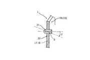
さらに、図1〜図5(a)において、電波吸収側壁1の前縦縁部17・後縦縁部18に、RFIDアンテナ8から放射される電波が所定の漏洩許容値以下であることを確認するための漏れ検出ICタグ9…が付設されている。ICタグ9…は細長直方体形状を有し、前側の折畳矩形板19bの前縦縁部17と、後側の折畳矩形板19bの後縦縁部18とに、着脱自在に取着される。具体的には、21は、内部にICタグ9を出し入れ自在な袋状のタグホルダであり、タグホルダ21の外部に形成された面状ファスナ22と、前・後折畳矩形板19bの前縦縁部17,後縦縁部18に形成された面状ファスナ20,20とにより、タグホルダ21が矩形板19bに着脱自在に取着される。 Furthermore, in FIG. 1 to FIG. 5A, it is confirmed that the radio wave radiated from the
そして、ICタグ9をタグホルダ21に内包させて、矩形板19bの前縦縁部17・後縦縁部18に取着される。着脱自在なので、上下の取着位置を、アンテナ8の設置高さや放射電波の大きさ・放射角等に応じて自由に変更できる(図4参照)。
また、アンテナ8から放射される電波の偏波面に合わせて、ICタグ9の取着状態を、縦長状(図4参照)や水平方向に横長状(図6参照)に変更できる。矩形板19b,19bの前縦縁部17・後縦縁部18には、夫々、一つ又は複数のICタグ9が取着される。また、図5(b)の実線と仮想線にて示すように、ICタグ9を、前縦縁部17・後縦縁部18の近傍の他の面に、位置変更可能に取着しても自由である。また、図6に示すように、所望の角度βをもって傾斜状に(角度可変に)取着しても良い。
なお、タグホルダ21を省略して、ICタグ9自体に面状ファスナ22を形成して、電波吸収側壁1に直接着脱自在とするのもよい。また、面状ファスナ20,22に替えて、両面テープにて、ICタグ9を電波吸収側壁1に取着するのもよい。Then, the
Further, the attachment state of the
The
図7は、電波吸収側壁1とビーム6の関係を示す説明用の要部平面図である。前折畳矩形板19bがXで示す状態の場合には、その前端縁部17及び漏れ検出ICタグ9がビーム6の範囲内に納まっており、ビーム6が、電波吸収側壁1を超えて(通路部13を挟んでアンテナ8の)反対側に漏れ出る。そして、RFIDアンテナ8が、ICタグ9を読み取るため、電波の(電波吸収側壁1を超えての)漏れを確認できる。 FIG. 7 is a plan view of a principal part for explanation showing the relationship between the radio wave
このように、電波の漏れを確認したら、折畳矩形板19bをXの状態からさらに展開させて、前端縁部17及びICタグ9がビーム6の範囲からはみ出るようにし(Yで示した状態)、ビーム6が電波吸収側壁1から漏れないようにする。即ち、ビーム6がICタグ9を読み取らなくなるまで、矩形板19bを展開させればよい。図示省略したが、電波吸収側壁1の後側の矩形板19bについても、上述の前側の折畳矩形板19bにおける説明と同様である。 In this way, when the leakage of radio waves is confirmed, the folded
ここで、図1,図2のゲート構造の組立の手順を説明する。設置場所に運搬する際には、電波吸収側壁1は、2枚の折畳矩形板19b,19bが中央矩形板19aに対してコンパクトな折畳状態(図3の実線の状態)であり、運搬がスムーズである。そして、設置場所において、RFIDアンテナ8と電波吸収側壁1の中央矩形板19aが通路部13を挟んで平行に対向状となるように、配設する。そして、上述したように、放射電波が電波吸収側壁1から漏れ出ないように、折畳矩形板19b,19bを所定角度まで展開させて調整し、図示省略の固定部材で不意に動かないようにすれば、セット完了である。 Here, the assembly procedure of the gate structure of FIGS. 1 and 2 will be described. When transporting to the installation location, the electromagnetic wave absorbing
次に、図8,図9は本発明に係るRFIDゲート構造の他の実施の形態を示し、図1,図2のゲート構造との相違点は、通路部13の両側に夫々、RFIDアンテナ8を配設し、かつ、通路部13を挟んで各RFIDアンテナ8の反対側に電波吸収側壁1を配設した点である。一側・他側のRFIDアンテナ8A,8Bは、夫々の電波放射面28,28が平行かつ対向状になるように同じ高さ位置又は相違する高さ位置として、側壁1の中央矩形板19aの表て面(通路部13側の面)にRFIDアンテナ8を固着する。また、一側・他側の電波吸収側壁1A,1Bは、夫々の中央矩形板19a,19aが相互に平行状として向かい合って、立設されている。各電波吸収側壁1とこれに対向するRFIDアンテナ8の配置、アンテナ8の設置高さ、各側壁1にICタグ9が取着される構成は、図1〜図5で説明した構成と同じである。 Next, FIGS. 8 and 9 show another embodiment of the RFID gate structure according to the present invention. The difference from the gate structure of FIGS. 1 and 2 is that the
さらに、一対の電波吸収側壁1A,1Bについて、前端縁部17,17の上部と、後端縁部18,18の上部が、夫々連結杆14にて着脱自在に連結される。なお、この連結杆14を省略することも可能である。
この図8,図9のゲート構造の組立の手順については、設置場所において、一対のRFIDアンテナ8A,8Bと一対の電波吸収側壁1A,1Bを通路部13を挟んで対向状に配設し、図1,図2のゲート構造の組立の手順と同様の手順で組み立てれば、セット完了である。なお、その後、一対の電波吸収側壁1A,1Bを連結杆14,14にて連結すれば、安定保持できて望ましい。つまり、連結杆14により、一対の側壁1A,1Bの位置変動や、折畳矩形板19bの不意の揺動が防がれる。Further, the upper ends of the front
8 and 9, the assembly procedure of the gate structure shown in FIGS. 8 and 9 is arranged in such a manner that a pair of
そして、一側のRFIDアンテナ8Aと他側のRFIDアンテナ8Bは、時間帯をずらして交互に送受信を行う。よって、例えば、大きな被識別体10の一側や他側に偏ってRFIDタグ7が付されていても、どちらかのRFIDアンテナ8がタグ情報を読み取ることができる。また、RFIDタグ7を付した多数の被識別体10…が台車に積まれている場合にも、全てのRFIDタグ7…を漏れなく、どちらかのRFIDアンテナ8が確実に読み取る。 Then, the
また、図1,図2,図8,図9の電波吸収側壁1は、3枚の矩形板19…を折畳展開可能に連結して形成されているが、これに限定されずに設計変更自由であり、2枚の矩形板19,19を折畳展開可能に連結して形成したものや、4枚以上の矩形板19…を折畳展開可能に連結して形成したものであってもよい(図示省略)。4枚以上の矩形板19…を連結して形成した場合にも、ICタグ9は、最も前側の矩形板19の前縦縁部17と、最も後側の矩形板19の後縦縁部18に着脱自在に取着される。なお、電波吸収側壁1の展開角度が最大 180°として平板状まで展開可能な構造としたときは、何らかの倒立防止の起立支持部材(図示省略)を要する。他方、図2や図9に示す角度を最大展開状態となるようにした構造の場合、そのままで自立可能であって、起立支持部材を省略することが可能となる。 1, 2, 8, and 9 are formed by connecting three
また、図示省略するが、通路部13の上方又は下方にRFIDアンテナ8を設置しても良く、図8,図9のように一対の側壁1,1を連結杆14,14で連結したゲート構造においては、各連結杆14に漏れ検出ICタグ9を設けることで、アンテナ8が放射する電波の漏れを確認することが可能となる。 Although not shown, the
以上のように、本発明に係るRFIDゲート構造は、RFIDタグ7を付設した被識別体10が通過する通路部13の一側に、RFIDタグ7に記憶させた情報を読み取るRFIDアンテナ8を配設し、かつ、通路部13を挟んで他側に電波吸収側壁1を配設し、電波吸収側壁1は、複数枚の縦細長状矩形板19をその縦端縁にて折畳展開可能に順次接続具11にて連結し、全体が折畳状態・展開状態の間で開閉自在に形成され、さらに、電波吸収側壁1の前縦縁部17・後縦縁部18に、RFIDアンテナ8から放射される平面視の電波が所定の漏洩許容値以下であることを確認するための漏れ検出ICタグ9,9を付設したものなので、アンテナ8から放射されるタグ情報を読み取る電波が、電波吸収側壁1から(通路部13を挟んでアンテナ8に対し)反対側に漏れていないかどうかを確認することができる。よって、読取を所望しない場所にあるタグ情報の読取を確実に防ぐことができる。そして、電波吸収側壁1は、全体が折畳状態・展開状態の間で開閉自在に形成されているので、ICタグ9により電波の漏れを確認した場合には、側壁1の展開状態を変動させることによって、電波が漏れないように調整することができる。 As described above, in the RFID gate structure according to the present invention, the
また、本発明に係るRFIDゲート構造は、RFIDタグ7を付設した被識別体10が通過する通路部13の両側に夫々、RFIDタグ7に記憶させた情報を読み取るRFIDアンテナ8を配設し、かつ、通路部13を挟んで各RFIDアンテナ8の反対側に電波吸収側壁1を配設し、各電波吸収側壁1は、複数枚の縦細長状矩形板19をその縦端縁にて折畳展開可能に順次接続具11にて連結し、全体が折畳状態・展開状態の間で開閉自在に形成され、さらに、電波吸収側壁1の前縦縁部17・後縦縁部18に、RFIDアンテナ8から放射される平面視の電波が所定の漏洩許容値以下であることを確認するための漏れ検出ICタグ9,9を付設したものなので、アンテナ8から放射されるタグ情報を読み取る電波が、電波吸収側壁1から(通路部13を挟んでアンテナ8に対し)反対側に漏れていないかどうかを確認することができる。よって、読取を所望しない場所にあるタグ情報の読取を確実に防ぐことができる。そして、電波吸収側壁1は、全体が折畳状態・展開状態の間で開閉自在に形成されているので、ICタグ9により電波の漏れを確認した場合には、側壁1の展開状態を変動させることで、電波が漏れないように調整することができる。
さらに、一側のRFIDアンテナ8Aと他側のRFIDアンテナ8Bを、時間帯をずらして交互に送受信することで、例えば、大きな被識別体10の一側や他側に偏ってRFIDタグ7が付されていても、どちらかのRFIDアンテナ8が確実に読み取ることができる。また、RFIDタグ7を付した多数の被識別体10…が台車に積まれている場合にも、どちらかのRFIDアンテナ8が、全てのRFIDタグ7…を漏れなく確実に読み取ることができる。さらに、RFIDアンテナ8は、そのアンテナ利得を増加させずに指向性が高まり技術的に合理的である。In addition, the RFID gate structure according to the present invention includes an
Further, by alternately transmitting and receiving the
また、漏れ検出ICタグ9は、電波吸収側壁1の縦縁部17,18に着脱自在に取着されるので、RFIDアンテナ8の設置高さや放射される電波の放射角θの大きさ等に応じて、ICタグ9の上下取着位置を自由に変えることができ、電波の漏れの有無(所定の漏洩許容値以下であること)を確実に確認することができる。また、細長状のICタグ9を用いる場合、放射される電波の偏波面に合わせて、ICタグ9の取着状態を横長状あるいは縦長状等様々に変更できるので、電波の漏れの有無の確認が一層確実になる。 In addition, since the leak
また、電波吸収側壁1の下縁部24に車輪25を付設したので、側壁1を折畳状態・展開状態の間でスムーズに揺動させることができる。よって、側壁1を開閉させて電波が側壁1から漏れないように調整する際や、側壁1を移動・組立する際等の作業効率を上昇させることができる。 Further, since the
1 電波吸収側壁
7 RFIDタグ
8 RFIDアンテナ
9 漏れ検出ICタグ
10 被識別体
11 接続具
13 通路部
17 前縦縁部
18 後縦縁部
19 矩形板
24 下縁部
25 車輪1 Radio wave
10 Identification object
11 Connector
13 Passage
17 Front vertical edge
18 Rear vertical edge
19 Rectangular plate
24 Lower edge
25 wheels
Claims (4)
Translated fromJapanese該電波吸収側壁(1)は、複数枚の縦細長状矩形板(19)をその縦端縁にて折畳展開可能に順次接続具(11)にて連結し、全体が折畳状態・展開状態の間で開閉自在に形成され、さらに、該電波吸収側壁(1)の前縦縁部(17)・後縦縁部(18)に、上記RFIDアンテナ(8)から放射される電波が所定の漏洩許容値以下であることを確認するための漏れ検出ICタグ(9)(9)を付設したことを特徴とするRFIDゲート構造。An RFID antenna (8) that reads information stored in the RFID tag (7) is disposed on one side of the passage (13) through which the identification target (10) provided with the RFID tag (7) passes, In addition, a radio wave absorption side wall (1) is disposed on the other side across the passage portion (13),
The electromagnetic wave absorption side wall (1) is connected to a plurality of vertically elongated rectangular plates (19) at their vertical edges so that they can be folded and unfolded sequentially with a connector (11), and the whole is folded and unfolded. The radio wave radiated from the RFID antenna (8) is formed on the front vertical edge (17) and rear vertical edge (18) of the radio wave absorption side wall (1). An RFID gate structure comprising a leakage detection IC tag (9) (9) for confirming that the leakage is less than or equal to the allowable leakage value.
各該電波吸収側壁(1)は、複数枚の縦細長状矩形板(19)をその縦端縁にて折畳展開可能に順次接続具(11)にて連結し、全体が折畳状態・展開状態の間で開閉自在に形成され、さらに、該電波吸収側壁(1)の前縦縁部(17)・後縦縁部(18)に、上記RFIDアンテナ(8)から放射される電波が所定の漏洩許容値以下であることを確認するための漏れ検出ICタグ(9)(9)を付設したことを特徴とするRFIDゲート構造。RFID antennas (8) for reading information stored in the RFID tag (7) are disposed on both sides of the passage (13) through which the identification target (10) provided with the RFID tag (7) passes, In addition, a radio wave absorption side wall (1) is disposed on the opposite side of each RFID antenna (8) across the passage portion (13),
Each of the electromagnetic wave absorption side walls (1) is connected to a plurality of vertically elongated rectangular plates (19) by means of a connecting tool (11) so that they can be folded and unfolded at their vertical edges. The radio wave radiated from the RFID antenna (8) is formed to be openable and closable between the unfolded state, and further to the front vertical edge (17) and the rear vertical edge (18) of the radio wave absorption side wall (1). An RFID gate structure comprising a leak detection IC tag (9) (9) for confirming that the value is less than a predetermined leak tolerance.
Priority Applications (4)
| Application Number | Priority Date | Filing Date | Title |
|---|---|---|---|
| JP2007076162AJP4953201B2 (en) | 2007-03-23 | 2007-03-23 | RFID gate structure |
| DE112007002942TDE112007002942T5 (en) | 2006-12-04 | 2007-12-03 | IC tag reader |
| US12/517,185US20100073141A1 (en) | 2006-12-04 | 2007-12-03 | Ic tag reading device |
| PCT/JP2007/073324WO2008069175A1 (en) | 2006-12-04 | 2007-12-03 | Ic tag reader |
Applications Claiming Priority (1)
| Application Number | Priority Date | Filing Date | Title |
|---|---|---|---|
| JP2007076162AJP4953201B2 (en) | 2007-03-23 | 2007-03-23 | RFID gate structure |
Publications (2)
| Publication Number | Publication Date |
|---|---|
| JP2008234527A JP2008234527A (en) | 2008-10-02 |
| JP4953201B2true JP4953201B2 (en) | 2012-06-13 |
Family
ID=39907194
Family Applications (1)
| Application Number | Title | Priority Date | Filing Date |
|---|---|---|---|
| JP2007076162AActiveJP4953201B2 (en) | 2006-12-04 | 2007-03-23 | RFID gate structure |
Country Status (1)
| Country | Link |
|---|---|
| JP (1) | JP4953201B2 (en) |
Cited By (1)
| Publication number | Priority date | Publication date | Assignee | Title |
|---|---|---|---|---|
| JP2017072995A (en)* | 2015-10-07 | 2017-04-13 | 東海電気株式会社 | Ic-tag reader |
Families Citing this family (13)
| Publication number | Priority date | Publication date | Assignee | Title |
|---|---|---|---|---|
| CN101672648A (en) | 2008-09-12 | 2010-03-17 | 富士通天株式会社 | Information processing device and image processing device |
| JP5439061B2 (en)* | 2009-06-30 | 2014-03-12 | 株式会社ケーヒン | Inspection gate system |
| KR20110104733A (en) | 2010-03-17 | 2011-09-23 | 엘에스산전 주식회사 | Gate system |
| JP5548496B2 (en)* | 2010-03-25 | 2014-07-16 | シスメックス株式会社 | Sample analyzer |
| JP6560081B2 (en)* | 2015-09-25 | 2019-08-14 | マスプロ電工株式会社 | RFID communication gate |
| PL235230B1 (en)* | 2018-01-16 | 2020-06-15 | Dataconsult Spolka Z Ograniczona Odpowiedzialnoscia | Selective RFID gate |
| JP7231070B2 (en)* | 2018-02-13 | 2023-03-01 | 大日本印刷株式会社 | Gate-type payment system and gate-type payment device |
| JP7035590B2 (en)* | 2018-02-13 | 2022-03-15 | 大日本印刷株式会社 | Gate-type settlement system and gate-type settlement device |
| EP3776327B1 (en)* | 2018-04-09 | 2025-01-29 | Fujitsu Frontech North America Inc. | Rfid multi-read portal |
| JP2020064569A (en)* | 2018-10-19 | 2020-04-23 | 東芝テック株式会社 | RFID reader |
| US11415669B2 (en)* | 2019-01-11 | 2022-08-16 | Nec Corporation | Walk-through gate with signal separation |
| JP7517434B2 (en) | 2020-08-27 | 2024-07-17 | 日本電気株式会社 | Gate device |
| JP7280583B1 (en)* | 2022-04-13 | 2023-05-24 | 俊宏 南 | RF tag reader |
Family Cites Families (5)
| Publication number | Priority date | Publication date | Assignee | Title |
|---|---|---|---|---|
| JPH0311907U (en)* | 1989-06-22 | 1991-02-06 | ||
| JP4865151B2 (en)* | 2001-06-14 | 2012-02-01 | サトーホールディングス株式会社 | Printer |
| KR20040096522A (en)* | 2002-01-09 | 2004-11-16 | 미드웨스트바코 코포레이션 | Intelligent station using multiple rf antennae and inventory control system and method incorporating same |
| JP2006246047A (en)* | 2005-03-03 | 2006-09-14 | Toshiba Tec Corp | Non-contact communication device |
| JP4670440B2 (en)* | 2005-04-07 | 2011-04-13 | オムロン株式会社 | Management system, management system control method, information processing apparatus, management system control program, and recording medium recording management system control program |
- 2007
- 2007-03-23JPJP2007076162Apatent/JP4953201B2/enactiveActive
Cited By (1)
| Publication number | Priority date | Publication date | Assignee | Title |
|---|---|---|---|---|
| JP2017072995A (en)* | 2015-10-07 | 2017-04-13 | 東海電気株式会社 | Ic-tag reader |
Also Published As
| Publication number | Publication date |
|---|---|
| JP2008234527A (en) | 2008-10-02 |
Similar Documents
| Publication | Publication Date | Title |
|---|---|---|
| JP4953201B2 (en) | RFID gate structure | |
| US7528726B2 (en) | RFID portal array antenna system | |
| US7389938B2 (en) | Radio communication system | |
| JP5121363B2 (en) | Communication improvement device, communication system, and article information handling facility | |
| US8258954B2 (en) | Frequency selective surface aids to the operation of RFID products | |
| JP4841659B2 (en) | Antenna device | |
| US20100109841A1 (en) | Reader and management system | |
| JP2009516944A (en) | Robust RFID antenna with low reflection loss | |
| US20080042846A1 (en) | Antenna for radio frequency identification systems | |
| JP2010157862A (en) | Communication antenna, rfid tag, contactless communication device, and contactless communication method | |
| WO2008069175A1 (en) | Ic tag reader | |
| JP2023114292A (en) | RF tag system | |
| JP2008140216A (en) | Ic tag reader | |
| JP2009504093A (en) | Antenna system | |
| JP4407617B2 (en) | Wireless communication system | |
| US20250202096A1 (en) | Moving robot | |
| WO2009107565A1 (en) | Rfid communication system | |
| JP2007294903A (en) | Shield joint structure and spatial former, and testing method using spatial former | |
| JP7429399B1 (en) | RF tag reader | |
| JP7014442B2 (en) | Reader | |
| JP2002230507A (en) | Data carrier system | |
| JP2008141566A (en) | Transmitting antenna | |
| JP3246270U (en) | radio frequency identification device | |
| JP7535385B2 (en) | Wireless tag reader | |
| JP7559411B2 (en) | RF tag reader |
Legal Events
| Date | Code | Title | Description |
|---|---|---|---|
| A621 | Written request for application examination | Free format text:JAPANESE INTERMEDIATE CODE: A621 Effective date:20100209 | |
| TRDD | Decision of grant or rejection written | ||
| A01 | Written decision to grant a patent or to grant a registration (utility model) | Free format text:JAPANESE INTERMEDIATE CODE: A01 Effective date:20120221 | |
| A01 | Written decision to grant a patent or to grant a registration (utility model) | Free format text:JAPANESE INTERMEDIATE CODE: A01 | |
| A61 | First payment of annual fees (during grant procedure) | Free format text:JAPANESE INTERMEDIATE CODE: A61 Effective date:20120306 | |
| R150 | Certificate of patent or registration of utility model | Free format text:JAPANESE INTERMEDIATE CODE: R150 Ref document number:4953201 Country of ref document:JP Free format text:JAPANESE INTERMEDIATE CODE: R150 | |
| FPAY | Renewal fee payment (event date is renewal date of database) | Free format text:PAYMENT UNTIL: 20150323 Year of fee payment:3 | |
| R250 | Receipt of annual fees | Free format text:JAPANESE INTERMEDIATE CODE: R250 | |
| R250 | Receipt of annual fees | Free format text:JAPANESE INTERMEDIATE CODE: R250 | |
| R250 | Receipt of annual fees | Free format text:JAPANESE INTERMEDIATE CODE: R250 | |
| R250 | Receipt of annual fees | Free format text:JAPANESE INTERMEDIATE CODE: R250 | |
| R250 | Receipt of annual fees | Free format text:JAPANESE INTERMEDIATE CODE: R250 | |
| R250 | Receipt of annual fees | Free format text:JAPANESE INTERMEDIATE CODE: R250 | |
| R250 | Receipt of annual fees | Free format text:JAPANESE INTERMEDIATE CODE: R250 | |
| R250 | Receipt of annual fees | Free format text:JAPANESE INTERMEDIATE CODE: R250 | |
| R250 | Receipt of annual fees | Free format text:JAPANESE INTERMEDIATE CODE: R250 |