JP4949108B2 - Surgical suturing instrument with foldable vacuum chamber - Google Patents
Surgical suturing instrument with foldable vacuum chamberDownload PDFInfo
- Publication number
- JP4949108B2 JP4949108B2JP2007092231AJP2007092231AJP4949108B2JP 4949108 B2JP4949108 B2JP 4949108B2JP 2007092231 AJP2007092231 AJP 2007092231AJP 2007092231 AJP2007092231 AJP 2007092231AJP 4949108 B2JP4949108 B2JP 4949108B2
- Authority
- JP
- Japan
- Prior art keywords
- suture
- needle
- vacuum chamber
- suturing instrument
- housing
- Prior art date
- Legal status (The legal status is an assumption and is not a legal conclusion. Google has not performed a legal analysis and makes no representation as to the accuracy of the status listed.)
- Expired - Fee Related
Links
- 238000003780insertionMethods0.000claimsabstractdescription14
- 230000037431insertionEffects0.000claimsabstractdescription14
- 230000014759maintenance of locationEffects0.000claimsdescription7
- 230000008602contractionEffects0.000claimsdescription6
- 229920001971elastomerPolymers0.000claimsdescription6
- 239000000806elastomerSubstances0.000claimsdescription6
- 238000000034methodMethods0.000abstractdescription84
- 238000001356surgical procedureMethods0.000abstractdescription7
- 230000000007visual effectEffects0.000abstractdescription7
- 238000001429visible spectrumMethods0.000abstractdescription3
- 230000007246mechanismEffects0.000description74
- 239000000853adhesiveSubstances0.000description28
- 230000001070adhesive effectEffects0.000description28
- 230000002496gastric effectEffects0.000description27
- 239000000565sealantSubstances0.000description21
- 230000009471actionEffects0.000description16
- 210000002784stomachAnatomy0.000description15
- 238000012800visualizationMethods0.000description14
- 239000012530fluidSubstances0.000description12
- 208000008589ObesityDiseases0.000description8
- 208000012696congenital leptin deficiencyDiseases0.000description6
- 230000003993interactionEffects0.000description6
- 208000001022morbid obesityDiseases0.000description6
- 230000008901benefitEffects0.000description5
- 238000003384imaging methodMethods0.000description5
- 229920000642polymerPolymers0.000description5
- CURLTUGMZLYLDI-UHFFFAOYSA-NCarbon dioxideChemical compoundO=C=OCURLTUGMZLYLDI-UHFFFAOYSA-N0.000description4
- 230000008878couplingEffects0.000description4
- 238000010168coupling processMethods0.000description4
- 238000005859coupling reactionMethods0.000description4
- 239000000463materialSubstances0.000description4
- 230000035515penetrationEffects0.000description4
- 230000002829reductive effectEffects0.000description4
- 230000017531blood circulationEffects0.000description3
- 210000000078clawAnatomy0.000description3
- 238000013461designMethods0.000description3
- 238000001125extrusionMethods0.000description3
- 230000004927fusionEffects0.000description3
- 239000007789gasSubstances0.000description3
- 210000003128headAnatomy0.000description3
- 208000014674injuryDiseases0.000description3
- 210000000936intestineAnatomy0.000description3
- 239000007788liquidSubstances0.000description3
- 210000000214mouthAnatomy0.000description3
- 230000009467reductionEffects0.000description3
- 230000000717retained effectEffects0.000description3
- 230000002441reversible effectEffects0.000description3
- 230000008733traumaEffects0.000description3
- 230000005355Hall effectEffects0.000description2
- 229910000831SteelInorganic materials0.000description2
- QVGXLLKOCUKJST-UHFFFAOYSA-Natomic oxygenChemical compound[O]QVGXLLKOCUKJST-UHFFFAOYSA-N0.000description2
- 229910002092carbon dioxideInorganic materials0.000description2
- 239000001569carbon dioxideSubstances0.000description2
- 230000000295complement effectEffects0.000description2
- 230000006835compressionEffects0.000description2
- 238000007906compressionMethods0.000description2
- 238000001514detection methodMethods0.000description2
- 239000012636effectorSubstances0.000description2
- 238000005516engineering processMethods0.000description2
- 230000006870functionEffects0.000description2
- 230000006872improvementEffects0.000description2
- 210000001630jejunumAnatomy0.000description2
- 230000000670limiting effectEffects0.000description2
- 238000002595magnetic resonance imagingMethods0.000description2
- 238000004519manufacturing processMethods0.000description2
- 235000020824obesityNutrition0.000description2
- 210000000056organAnatomy0.000description2
- 229910052760oxygenInorganic materials0.000description2
- 239000001301oxygenSubstances0.000description2
- 230000002980postoperative effectEffects0.000description2
- 238000011084recoveryMethods0.000description2
- 238000009958sewingMethods0.000description2
- 210000000813small intestineAnatomy0.000description2
- 125000006850spacer groupChemical group0.000description2
- 239000010959steelSubstances0.000description2
- 238000002604ultrasonographyMethods0.000description2
- 200000000007Arterial diseaseDiseases0.000description1
- 206010007559Cardiac failure congestiveDiseases0.000description1
- JOYRKODLDBILNP-UHFFFAOYSA-NEthyl urethaneChemical compoundCCOC(N)=OJOYRKODLDBILNP-UHFFFAOYSA-N0.000description1
- 206010019280Heart failuresDiseases0.000description1
- 206010020772HypertensionDiseases0.000description1
- 206010025476MalabsorptionDiseases0.000description1
- 208000004155Malabsorption SyndromesDiseases0.000description1
- 206010037448Pulmonary valve incompetenceDiseases0.000description1
- 208000006011StrokeDiseases0.000description1
- 210000001015abdomenAnatomy0.000description1
- 238000010521absorption reactionMethods0.000description1
- 230000003213activating effectEffects0.000description1
- 230000003872anastomosisEffects0.000description1
- 238000004873anchoringMethods0.000description1
- 238000013459approachMethods0.000description1
- 208000028922artery diseaseDiseases0.000description1
- 238000007681bariatric surgeryMethods0.000description1
- 230000004888barrier functionEffects0.000description1
- 239000008280bloodSubstances0.000description1
- 210000004369bloodAnatomy0.000description1
- 210000001124body fluidAnatomy0.000description1
- 235000019577caloric intakeNutrition0.000description1
- 230000008859changeEffects0.000description1
- 238000004040coloringMethods0.000description1
- 238000013270controlled releaseMethods0.000description1
- 238000007796conventional methodMethods0.000description1
- 238000011161developmentMethods0.000description1
- 206010012601diabetes mellitusDiseases0.000description1
- 238000010586diagramMethods0.000description1
- 230000001079digestive effectEffects0.000description1
- 238000009826distributionMethods0.000description1
- 230000002183duodenal effectEffects0.000description1
- 230000000694effectsEffects0.000description1
- 239000013013elastic materialSubstances0.000description1
- 230000002708enhancing effectEffects0.000description1
- 235000019525fullnessNutrition0.000description1
- 210000004051gastric juiceAnatomy0.000description1
- 210000002767hepatic arteryAnatomy0.000description1
- 210000003405ileumAnatomy0.000description1
- 238000003331infrared imagingMethods0.000description1
- 210000004185liverAnatomy0.000description1
- 238000007726management methodMethods0.000description1
- 239000000155meltSubstances0.000description1
- 238000002844meltingMethods0.000description1
- 230000008018meltingEffects0.000description1
- 239000002184metalSubstances0.000description1
- 238000012986modificationMethods0.000description1
- 230000004048modificationEffects0.000description1
- 230000000399orthopedic effectEffects0.000description1
- 210000000496pancreasAnatomy0.000description1
- 230000036961partial effectEffects0.000description1
- 230000002572peristaltic effectEffects0.000description1
- 230000002265preventionEffects0.000description1
- 230000008569processEffects0.000description1
- 201000010298pulmonary valve insufficiencyDiseases0.000description1
- 230000008439repair processEffects0.000description1
- 230000004043responsivenessEffects0.000description1
- 229920003031santoprenePolymers0.000description1
- 235000019627satietyNutrition0.000description1
- 230000036186satietyEffects0.000description1
- 238000001228spectrumMethods0.000description1
- 230000008961swellingEffects0.000description1
- 230000009466transformationEffects0.000description1
- 238000013519translationMethods0.000description1
- 210000001835visceraAnatomy0.000description1
- 238000007794visualization techniqueMethods0.000description1
- 239000011800void materialSubstances0.000description1
- 230000004580weight lossEffects0.000description1
- 238000004804windingMethods0.000description1
Images


Classifications
- A—HUMAN NECESSITIES
- A61—MEDICAL OR VETERINARY SCIENCE; HYGIENE
- A61B—DIAGNOSIS; SURGERY; IDENTIFICATION
- A61B1/00—Instruments for performing medical examinations of the interior of cavities or tubes of the body by visual or photographical inspection, e.g. endoscopes; Illuminating arrangements therefor
- A61B1/005—Flexible endoscopes
- A—HUMAN NECESSITIES
- A61—MEDICAL OR VETERINARY SCIENCE; HYGIENE
- A61B—DIAGNOSIS; SURGERY; IDENTIFICATION
- A61B1/00—Instruments for performing medical examinations of the interior of cavities or tubes of the body by visual or photographical inspection, e.g. endoscopes; Illuminating arrangements therefor
- A61B1/00064—Constructional details of the endoscope body
- A61B1/00071—Insertion part of the endoscope body
- A61B1/0008—Insertion part of the endoscope body characterised by distal tip features
- A61B1/00087—Tools
- A—HUMAN NECESSITIES
- A61—MEDICAL OR VETERINARY SCIENCE; HYGIENE
- A61B—DIAGNOSIS; SURGERY; IDENTIFICATION
- A61B1/00—Instruments for performing medical examinations of the interior of cavities or tubes of the body by visual or photographical inspection, e.g. endoscopes; Illuminating arrangements therefor
- A61B1/00064—Constructional details of the endoscope body
- A61B1/00071—Insertion part of the endoscope body
- A61B1/0008—Insertion part of the endoscope body characterised by distal tip features
- A61B1/00094—Suction openings
- A—HUMAN NECESSITIES
- A61—MEDICAL OR VETERINARY SCIENCE; HYGIENE
- A61B—DIAGNOSIS; SURGERY; IDENTIFICATION
- A61B1/00—Instruments for performing medical examinations of the interior of cavities or tubes of the body by visual or photographical inspection, e.g. endoscopes; Illuminating arrangements therefor
- A61B1/00131—Accessories for endoscopes
- A61B1/00133—Drive units for endoscopic tools inserted through or with the endoscope
- A—HUMAN NECESSITIES
- A61—MEDICAL OR VETERINARY SCIENCE; HYGIENE
- A61B—DIAGNOSIS; SURGERY; IDENTIFICATION
- A61B1/00—Instruments for performing medical examinations of the interior of cavities or tubes of the body by visual or photographical inspection, e.g. endoscopes; Illuminating arrangements therefor
- A61B1/00131—Accessories for endoscopes
- A61B1/0014—Fastening element for attaching accessories to the outside of an endoscope, e.g. clips, clamps or bands
- A—HUMAN NECESSITIES
- A61—MEDICAL OR VETERINARY SCIENCE; HYGIENE
- A61B—DIAGNOSIS; SURGERY; IDENTIFICATION
- A61B1/00—Instruments for performing medical examinations of the interior of cavities or tubes of the body by visual or photographical inspection, e.g. endoscopes; Illuminating arrangements therefor
- A61B1/273—Instruments for performing medical examinations of the interior of cavities or tubes of the body by visual or photographical inspection, e.g. endoscopes; Illuminating arrangements therefor for the upper alimentary canal, e.g. oesophagoscopes, gastroscopes
- A61B1/2736—Gastroscopes
- A—HUMAN NECESSITIES
- A61—MEDICAL OR VETERINARY SCIENCE; HYGIENE
- A61B—DIAGNOSIS; SURGERY; IDENTIFICATION
- A61B17/00—Surgical instruments, devices or methods
- A61B17/04—Surgical instruments, devices or methods for suturing wounds; Holders or packages for needles or suture materials
- A61B17/0469—Suturing instruments for use in minimally invasive surgery, e.g. endoscopic surgery
- A—HUMAN NECESSITIES
- A61—MEDICAL OR VETERINARY SCIENCE; HYGIENE
- A61B—DIAGNOSIS; SURGERY; IDENTIFICATION
- A61B17/00—Surgical instruments, devices or methods
- A61B17/04—Surgical instruments, devices or methods for suturing wounds; Holders or packages for needles or suture materials
- A61B17/0482—Needle or suture guides
- A—HUMAN NECESSITIES
- A61—MEDICAL OR VETERINARY SCIENCE; HYGIENE
- A61B—DIAGNOSIS; SURGERY; IDENTIFICATION
- A61B17/00—Surgical instruments, devices or methods
- A61B17/04—Surgical instruments, devices or methods for suturing wounds; Holders or packages for needles or suture materials
- A61B17/06—Needles ; Sutures; Needle-suture combinations; Holders or packages for needles or suture materials
- A61B17/06066—Needles, e.g. needle tip configurations
- A—HUMAN NECESSITIES
- A61—MEDICAL OR VETERINARY SCIENCE; HYGIENE
- A61B—DIAGNOSIS; SURGERY; IDENTIFICATION
- A61B17/00—Surgical instruments, devices or methods
- A61B17/04—Surgical instruments, devices or methods for suturing wounds; Holders or packages for needles or suture materials
- A61B17/06—Needles ; Sutures; Needle-suture combinations; Holders or packages for needles or suture materials
- A61B17/062—Needle manipulators
- A—HUMAN NECESSITIES
- A61—MEDICAL OR VETERINARY SCIENCE; HYGIENE
- A61B—DIAGNOSIS; SURGERY; IDENTIFICATION
- A61B1/00—Instruments for performing medical examinations of the interior of cavities or tubes of the body by visual or photographical inspection, e.g. endoscopes; Illuminating arrangements therefor
- A61B1/313—Instruments for performing medical examinations of the interior of cavities or tubes of the body by visual or photographical inspection, e.g. endoscopes; Illuminating arrangements therefor for introducing through surgical openings, e.g. laparoscopes
- A—HUMAN NECESSITIES
- A61—MEDICAL OR VETERINARY SCIENCE; HYGIENE
- A61B—DIAGNOSIS; SURGERY; IDENTIFICATION
- A61B17/00—Surgical instruments, devices or methods
- A61B17/00491—Surgical glue applicators
- A—HUMAN NECESSITIES
- A61—MEDICAL OR VETERINARY SCIENCE; HYGIENE
- A61B—DIAGNOSIS; SURGERY; IDENTIFICATION
- A61B17/00—Surgical instruments, devices or methods
- A61B17/04—Surgical instruments, devices or methods for suturing wounds; Holders or packages for needles or suture materials
- A61B17/0466—Suture bridges
- A—HUMAN NECESSITIES
- A61—MEDICAL OR VETERINARY SCIENCE; HYGIENE
- A61B—DIAGNOSIS; SURGERY; IDENTIFICATION
- A61B17/00—Surgical instruments, devices or methods
- A61B17/04—Surgical instruments, devices or methods for suturing wounds; Holders or packages for needles or suture materials
- A61B17/0487—Suture clamps, clips or locks, e.g. for replacing suture knots; Instruments for applying or removing suture clamps, clips or locks
- A—HUMAN NECESSITIES
- A61—MEDICAL OR VETERINARY SCIENCE; HYGIENE
- A61B—DIAGNOSIS; SURGERY; IDENTIFICATION
- A61B17/00—Surgical instruments, devices or methods
- A61B17/04—Surgical instruments, devices or methods for suturing wounds; Holders or packages for needles or suture materials
- A61B17/0493—Protective devices for suturing, i.e. for protecting the patient's organs or the operator
- A—HUMAN NECESSITIES
- A61—MEDICAL OR VETERINARY SCIENCE; HYGIENE
- A61B—DIAGNOSIS; SURGERY; IDENTIFICATION
- A61B17/00—Surgical instruments, devices or methods
- A61B2017/00017—Electrical control of surgical instruments
- A61B2017/00022—Sensing or detecting at the treatment site
- A—HUMAN NECESSITIES
- A61—MEDICAL OR VETERINARY SCIENCE; HYGIENE
- A61B—DIAGNOSIS; SURGERY; IDENTIFICATION
- A61B17/00—Surgical instruments, devices or methods
- A61B17/00234—Surgical instruments, devices or methods for minimally invasive surgery
- A61B2017/00292—Surgical instruments, devices or methods for minimally invasive surgery mounted on or guided by flexible, e.g. catheter-like, means
- A61B2017/00296—Surgical instruments, devices or methods for minimally invasive surgery mounted on or guided by flexible, e.g. catheter-like, means mounted on an endoscope
- A—HUMAN NECESSITIES
- A61—MEDICAL OR VETERINARY SCIENCE; HYGIENE
- A61B—DIAGNOSIS; SURGERY; IDENTIFICATION
- A61B17/00—Surgical instruments, devices or methods
- A61B2017/00367—Details of actuation of instruments, e.g. relations between pushing buttons, or the like, and activation of the tool, working tip, or the like
- A61B2017/00407—Ratchet means
- A—HUMAN NECESSITIES
- A61—MEDICAL OR VETERINARY SCIENCE; HYGIENE
- A61B—DIAGNOSIS; SURGERY; IDENTIFICATION
- A61B17/00—Surgical instruments, devices or methods
- A61B2017/0046—Surgical instruments, devices or methods with a releasable handle; with handle and operating part separable
- A61B2017/00469—Surgical instruments, devices or methods with a releasable handle; with handle and operating part separable for insertion of instruments, e.g. guide wire, optical fibre
- A—HUMAN NECESSITIES
- A61—MEDICAL OR VETERINARY SCIENCE; HYGIENE
- A61B—DIAGNOSIS; SURGERY; IDENTIFICATION
- A61B17/00—Surgical instruments, devices or methods
- A61B2017/00477—Coupling
- A—HUMAN NECESSITIES
- A61—MEDICAL OR VETERINARY SCIENCE; HYGIENE
- A61B—DIAGNOSIS; SURGERY; IDENTIFICATION
- A61B17/00—Surgical instruments, devices or methods
- A61B2017/00535—Surgical instruments, devices or methods pneumatically or hydraulically operated
- A61B2017/00561—Surgical instruments, devices or methods pneumatically or hydraulically operated creating a vacuum
- A—HUMAN NECESSITIES
- A61—MEDICAL OR VETERINARY SCIENCE; HYGIENE
- A61B—DIAGNOSIS; SURGERY; IDENTIFICATION
- A61B17/00—Surgical instruments, devices or methods
- A61B17/04—Surgical instruments, devices or methods for suturing wounds; Holders or packages for needles or suture materials
- A61B17/0469—Suturing instruments for use in minimally invasive surgery, e.g. endoscopic surgery
- A61B2017/0479—Packages or dispensers for MIS suturing instruments
- A—HUMAN NECESSITIES
- A61—MEDICAL OR VETERINARY SCIENCE; HYGIENE
- A61B—DIAGNOSIS; SURGERY; IDENTIFICATION
- A61B17/00—Surgical instruments, devices or methods
- A61B17/04—Surgical instruments, devices or methods for suturing wounds; Holders or packages for needles or suture materials
- A61B2017/0496—Surgical instruments, devices or methods for suturing wounds; Holders or packages for needles or suture materials for tensioning sutures
- A—HUMAN NECESSITIES
- A61—MEDICAL OR VETERINARY SCIENCE; HYGIENE
- A61B—DIAGNOSIS; SURGERY; IDENTIFICATION
- A61B17/00—Surgical instruments, devices or methods
- A61B17/04—Surgical instruments, devices or methods for suturing wounds; Holders or packages for needles or suture materials
- A61B17/06—Needles ; Sutures; Needle-suture combinations; Holders or packages for needles or suture materials
- A61B17/06066—Needles, e.g. needle tip configurations
- A61B2017/06076—Needles, e.g. needle tip configurations helically or spirally coiled
- A—HUMAN NECESSITIES
- A61—MEDICAL OR VETERINARY SCIENCE; HYGIENE
- A61B—DIAGNOSIS; SURGERY; IDENTIFICATION
- A61B17/00—Surgical instruments, devices or methods
- A61B17/04—Surgical instruments, devices or methods for suturing wounds; Holders or packages for needles or suture materials
- A61B17/06—Needles ; Sutures; Needle-suture combinations; Holders or packages for needles or suture materials
- A61B17/06066—Needles, e.g. needle tip configurations
- A61B2017/0608—J-shaped
- A—HUMAN NECESSITIES
- A61—MEDICAL OR VETERINARY SCIENCE; HYGIENE
- A61B—DIAGNOSIS; SURGERY; IDENTIFICATION
- A61B17/00—Surgical instruments, devices or methods
- A61B17/04—Surgical instruments, devices or methods for suturing wounds; Holders or packages for needles or suture materials
- A61B17/06—Needles ; Sutures; Needle-suture combinations; Holders or packages for needles or suture materials
- A61B17/06166—Sutures
- A61B2017/06185—Sutures hollow or tubular
- A—HUMAN NECESSITIES
- A61—MEDICAL OR VETERINARY SCIENCE; HYGIENE
- A61B—DIAGNOSIS; SURGERY; IDENTIFICATION
- A61B17/00—Surgical instruments, devices or methods
- A61B17/30—Surgical pincettes, i.e. surgical tweezers without pivotal connections
- A61B2017/306—Surgical pincettes, i.e. surgical tweezers without pivotal connections holding by means of suction
- A—HUMAN NECESSITIES
- A61—MEDICAL OR VETERINARY SCIENCE; HYGIENE
- A61B—DIAGNOSIS; SURGERY; IDENTIFICATION
- A61B90/00—Instruments, implements or accessories specially adapted for surgery or diagnosis and not covered by any of the groups A61B1/00 - A61B50/00, e.g. for luxation treatment or for protecting wound edges
- A61B90/03—Automatic limiting or abutting means, e.g. for safety
- A61B2090/037—Automatic limiting or abutting means, e.g. for safety with a frangible part, e.g. by reduced diameter
- A—HUMAN NECESSITIES
- A61—MEDICAL OR VETERINARY SCIENCE; HYGIENE
- A61B—DIAGNOSIS; SURGERY; IDENTIFICATION
- A61B90/00—Instruments, implements or accessories specially adapted for surgery or diagnosis and not covered by any of the groups A61B1/00 - A61B50/00, e.g. for luxation treatment or for protecting wound edges
- A61B90/08—Accessories or related features not otherwise provided for
- A61B2090/0807—Indication means
- A61B2090/0811—Indication means for the position of a particular part of an instrument with respect to the rest of the instrument, e.g. position of the anvil of a stapling instrument
- A—HUMAN NECESSITIES
- A61—MEDICAL OR VETERINARY SCIENCE; HYGIENE
- A61B—DIAGNOSIS; SURGERY; IDENTIFICATION
- A61B90/00—Instruments, implements or accessories specially adapted for surgery or diagnosis and not covered by any of the groups A61B1/00 - A61B50/00, e.g. for luxation treatment or for protecting wound edges
- A61B90/36—Image-producing devices or illumination devices not otherwise provided for
- A61B90/37—Surgical systems with images on a monitor during operation
- A61B2090/374—NMR or MRI
- A—HUMAN NECESSITIES
- A61—MEDICAL OR VETERINARY SCIENCE; HYGIENE
- A61B—DIAGNOSIS; SURGERY; IDENTIFICATION
- A61B90/00—Instruments, implements or accessories specially adapted for surgery or diagnosis and not covered by any of the groups A61B1/00 - A61B50/00, e.g. for luxation treatment or for protecting wound edges
- A61B90/36—Image-producing devices or illumination devices not otherwise provided for
- A61B90/37—Surgical systems with images on a monitor during operation
- A61B2090/378—Surgical systems with images on a monitor during operation using ultrasound
- A—HUMAN NECESSITIES
- A61—MEDICAL OR VETERINARY SCIENCE; HYGIENE
- A61B—DIAGNOSIS; SURGERY; IDENTIFICATION
- A61B34/00—Computer-aided surgery; Manipulators or robots specially adapted for use in surgery
- A61B34/20—Surgical navigation systems; Devices for tracking or guiding surgical instruments, e.g. for frameless stereotaxis
- A—HUMAN NECESSITIES
- A61—MEDICAL OR VETERINARY SCIENCE; HYGIENE
- A61B—DIAGNOSIS; SURGERY; IDENTIFICATION
- A61B5/00—Measuring for diagnostic purposes; Identification of persons
- A61B5/02—Detecting, measuring or recording for evaluating the cardiovascular system, e.g. pulse, heart rate, blood pressure or blood flow
- A61B5/026—Measuring blood flow
- A61B5/0261—Measuring blood flow using optical means, e.g. infrared light
- A—HUMAN NECESSITIES
- A61—MEDICAL OR VETERINARY SCIENCE; HYGIENE
- A61B—DIAGNOSIS; SURGERY; IDENTIFICATION
- A61B90/00—Instruments, implements or accessories specially adapted for surgery or diagnosis and not covered by any of the groups A61B1/00 - A61B50/00, e.g. for luxation treatment or for protecting wound edges
- A61B90/36—Image-producing devices or illumination devices not otherwise provided for
Landscapes
- Health & Medical Sciences (AREA)
- Life Sciences & Earth Sciences (AREA)
- Surgery (AREA)
- General Health & Medical Sciences (AREA)
- Public Health (AREA)
- Veterinary Medicine (AREA)
- Nuclear Medicine, Radiotherapy & Molecular Imaging (AREA)
- Animal Behavior & Ethology (AREA)
- Molecular Biology (AREA)
- Engineering & Computer Science (AREA)
- Biomedical Technology (AREA)
- Heart & Thoracic Surgery (AREA)
- Medical Informatics (AREA)
- Biophysics (AREA)
- Radiology & Medical Imaging (AREA)
- Physics & Mathematics (AREA)
- Pathology (AREA)
- Optics & Photonics (AREA)
- Gastroenterology & Hepatology (AREA)
- Surgical Instruments (AREA)
- Endoscopes (AREA)
- Materials For Medical Uses (AREA)
Abstract
Description
Translated fromJapanese〔関連出願の相互参照〕
本願は、2005年6月13日に出願された米国特許出願第11/150,481号(発明の名称:「内視鏡縫合装置(ENDOSCOPIC SUTURING DEVICE)」)の一部継続出願である。[Cross-reference of related applications]
This application is a continuation-in-part of US patent application Ser. No. 11 / 150,481, filed Jun. 13, 2005 (Title of Invention: “ENDOSCOPIC SUTURING DEVICE”).
〔発明の背景〕
1.発明の分野
本発明は、外科用縫合器械に関する。特に、本発明は、折り畳み式真空チャンバを備えた外科用縫合器械に関する。BACKGROUND OF THE INVENTION
1. The present invention relates to surgical suturing instruments. In particular, the present invention relates to a surgical suturing instrument with a collapsible vacuum chamber.
2.先行技術の説明
内視鏡下手技は、過去10年間にわたって急速に開発されている。これら手技は、修復を必要とする内部器官または組織を露出させるのに大きな外部開口部を必要とする従来の技術と比較して、外傷を最小限に抑える外科手技の遂行を可能にする場合が多い。内視鏡下手技が利用される多くの領域に加えて、内視鏡下手技は、病的肥満に取り組む外科手技用に開発された。病的肥満は、深刻な医学的状態である。事実、病的肥満は、米国だけでなく他の国でも非常に蔓延してきており、その流れは、否定的な方向に向いているように思われる。病的肥満と関連した合併症としては、平均余命を著しく減少させる高血圧症、糖尿病、肝動脈疾患、発作、うっ血性心不全、多発性整形外科的問題および肺動脈弁閉鎖不全症が挙げられる。このことを念頭において、当業者であれば確信されるように、病的肥満と関連した金銭上および身体上の代価は、相当大きなものである。事実、肥満と関連したコストは、米国だけでも1,000億ドルを超えると推定される。2. Description of Prior Art Endoscopic procedures have been rapidly developed over the past decade. These procedures may allow the performance of surgical procedures that minimize trauma compared to conventional techniques that require large external openings to expose internal organs or tissues that require repair. Many. In addition to the many areas where endoscopic procedures are utilized, endoscopic procedures have been developed for surgical procedures that address morbid obesity. Morbid obesity is a serious medical condition. In fact, morbid obesity has become very widespread not only in the United States, but also in other countries, and the trend seems to be in a negative direction. Complications associated with morbid obesity include hypertension that significantly reduces life expectancy, diabetes, hepatic artery disease, stroke, congestive heart failure, multiple orthopedic problems, and pulmonary valve insufficiency. With this in mind, the financial and physical price associated with morbid obesity is substantial, as one skilled in the art will be convinced. In fact, the costs associated with obesity are estimated to exceed $ 100 billion in the United States alone.
肥満を治療するために様々な外科手技が開発された。一手技は、ルーY胃バイパス(RYGB)である。この手技は非常に複雑であり、病的肥満状態の人を治療するために一般的に利用されている。約35,000件以上の手技が、米国だけで毎年行われている。他形態の肥満外科手術としては、フォビパウチ(Fobi pouch)および胆膵路転換手術(bilio-pancreatic diversion)および胃形成術または「胃ステープル留め(ステープリング)」が挙げられる。加うるに、胃を通る食べ物の流通を制限し、飽満感に影響を及ぼす植え込み型器具が知られている。 Various surgical procedures have been developed to treat obesity. One procedure is the Lou Y gastric bypass (RYGB). This procedure is very complex and is commonly used to treat people with morbid obesity. Over 35,000 procedures are performed every year in the United States alone. Other forms of bariatric surgery include Fobi pouch and bilio-pancreatic diversion and gastroplasty or “gastric stapling”. In addition, implantable devices are known that limit the distribution of food through the stomach and affect satiety.
RYGBでは、ルーYループを用いて高い位置への空腸の移動が行われる。胃は、自動ステープル留め器具を用いて2つの互いに等しくない部分(小さな上側部分と大きな下側胃嚢)に完全に分割される。上側嚢は典型的には、29.6mL(約1オンス(または20cc))未満という測定容量であり、これに対し、大きな下側胃嚢は、一般に手つかずの状態のままであり、腸管を通って流れる胃液を分泌し続ける。 In RYGB, the jejunum is moved to a higher position using the Lou Y loop. The stomach is completely divided into two unequal parts (small upper part and large lower gastric pouch) using an automatic stapling instrument. The upper sac typically has a measured volume of less than 29.6 mL (about 1 ounce (or 20 cc)), whereas the large lower gastric sac is generally left untouched and passes through the intestine. Continue to secrete flowing gastric juice.
次に、小腸の一部を下腹から持ってきてこれを上側胃嚢に接合し、それにより小口とも呼ばれる1.28cm(1/2インチ)の開口部を貫通して形成される吻合部を形成する。小腸のこの部分は、「ルーループ」ルーリム(“Roux loop” Roux limb)」と呼ばれており、食べ物を上側胃嚢から腸の残部まで運搬し、この腸残部で食べ物が消化される。次に、残りの下側胃嚢と取付け状態の十二指腸部分を再び連結して典型的にはステープル留め器械を用いて胃から約50〜150cm離れた場所でルーループリムへの別の吻合連結部を形成する。胃バイパス、膵臓および肝臓からの消化液が、空腸および回腸に流入するこの連結部で食べ物の消化を助ける。上側胃嚢のサイズが小さいので、患者は、ゆっくりとした速度で食事をせざるを得なくなり、はるかに早く飽満感を得る。この結果、カロリー摂取量が減少する。 Next, a part of the small intestine is brought from the lower abdomen and joined to the upper gastric sac, thereby forming an anastomosis formed through a 1.28 cm (1/2 inch) opening, also referred to as the small mouth. To do. This part of the small intestine is called the “Roux loop” Roux limb, which carries food from the upper gastric sac to the rest of the intestine where it is digested. The remaining lower gastric sac and the attached duodenal segment are then reconnected and another anastomotic connection to the loop loop rim is typically made about 50-150 cm away from the stomach using a stapling instrument. Form. Digestive fluids from the gastric bypass, pancreas and liver help digest food at this junction that flows into the jejunum and ileum. Because of the small size of the upper gastric sac, patients are forced to eat at a slow rate and get a sense of fullness much faster. As a result, calorie intake is reduced.
当業者には確実に理解されるように、従来型RYGB手技では、長時間にわたる手術時間が必要である。侵襲度が高いので、術後回復時間は、極めて長く、しかも激しい苦痛を伴う場合がある。現行のRYGB手技の侵襲性が高いことを考慮して、侵襲性の低い他の手技が開発された。このことを念頭に置いて、胃のサイズを減少させる他の手技が開発された。胃縮小術の最も一般的な形態では、縦ステープルを胃に沿って留めて適当な嚢を作る。この手技は、通常腹腔鏡下で行われ、したがって、相当な術前、術中、術後対策を必要とする。 As will be appreciated by those skilled in the art, conventional RYGB procedures require long surgical times. Due to the high degree of invasiveness, the postoperative recovery time is extremely long and may be accompanied by severe pain. In view of the high invasiveness of current RYGB procedures, other less invasive procedures have been developed. With this in mind, other procedures have been developed to reduce stomach size. In the most common form of gastric reduction, longitudinal staples are clamped along the stomach to create a suitable sac. This procedure is usually performed laparoscopically and therefore requires considerable pre-, intra- and post-operative measures.
内視鏡的器械および内視鏡下手技が開発されたので、外科医は、外傷を最小限に抑えると共に手技および回復に必要な時間を減少させようとして、例えば上述したような胃手技に内視鏡下技術を用い始めている。上記のことを念頭において、胃縮小術を時間効率が良く、しかも患者に優しい仕方で行うことができる手法および器械が必要である。 With the development of endoscopic instruments and endoscopic procedures, surgeons are able to perform endoscopic procedures such as those described above in an attempt to minimize trauma and reduce the time required for procedures and recovery. Began using mirror technology. With the above in mind, there is a need for techniques and instruments that allow gastric reduction to be performed in a time-efficient and patient-friendly manner.
適切には取り組まれてはいなかったある分野が、これら胃および他の内視鏡下手技が行われているときに縫合糸を付けるために必要である。本発明は、縫合糸の連続付けのために構成された内視鏡的縫合器械を提供する。 Certain areas that have not been properly addressed are necessary to apply sutures when these stomach and other endoscopic procedures are being performed. The present invention provides an endoscopic suturing instrument configured for suture continuation.
〔発明の概要〕
したがって、本発明の目的は、外科用縫合器械を提供することにある。外科用縫合器械は、縫合糸ハウジングと、弧状経路に沿って動くことができるよう縫合糸ハウジング内に設けられた針と、針に作動可能に関連していて、縫合糸を組織に付けやすくする仕方で縫合糸が固定された状態の針の弧状経路に沿う運動を制御する駆動組立体と、縫合糸ハウジングを収納する折り畳み式真空チャンバとを有する。真空チャンバは、真空ラインに結合可能な寸法形状になっている。[Summary of the Invention]
Accordingly, it is an object of the present invention to provide a surgical suturing instrument. The surgical suturing instrument is operatively associated with a suture housing, a needle disposed within the suture housing for movement along an arcuate path, and facilitates attachment of the suture to tissue. A drive assembly that controls movement of the needle along the arcuate path with the suture secured in a manner and a foldable vacuum chamber that houses the suture housing. The vacuum chamber is dimensioned to be connectable to a vacuum line.
また、本発明の目的は、駆動組立体が、針を連続円形経路に沿って動かす、縫合器械を提供することにある。 It is also an object of the present invention to provide a suturing instrument in which a drive assembly moves a needle along a continuous circular path.
本発明の別の目的は、真空チャンバが、真空チャンバの内壁に沿って設けられていて、かつ、真空チャンバへの組織の保持を促進する突起を有する、縫合器械を提供することにある。 Another object of the present invention is to provide a suturing instrument in which a vacuum chamber is provided along the inner wall of the vacuum chamber and has a protrusion that facilitates retention of tissue in the vacuum chamber.
本発明の別の目的は、真空チャンバが、真空チャンバの膨張および収縮を可能にする一体ヒンジ(living hinges)を有する、縫合器械を提供することにある。 Another object of the present invention is to provide a suturing instrument in which the vacuum chamber has living hinges that allow expansion and contraction of the vacuum chamber.
また、本発明の目的は、真空チャンバが、弾性である、縫合器械を提供することにある。 It is also an object of the present invention to provide a suturing instrument in which the vacuum chamber is elastic.
また、本発明の別の目的は、真空チャンバが、エラストマーである、縫合器械を提供することにある。 It is another object of the present invention to provide a suturing instrument in which the vacuum chamber is an elastomer.
本発明の更に別の目的は、縫合糸ハウジングが、患者の生まれつき備わった開口中に挿入可能な寸法形状になっている、縫合器械を提供することにある。 Yet another object of the present invention is to provide a suturing instrument wherein the suture housing is dimensioned to be insertable into a patient's natural opening.
本発明の更に別の目的は、縫合糸ハウジングは、直径が約3mm〜約24mmの開口を通過可能な寸法形状になっている、縫合器械を提供することにある。 Yet another object of the present invention is to provide a suture instrument wherein the suture housing is dimensioned to pass through an opening having a diameter of about 3 mm to about 24 mm.
また、本発明の目的は、縫合糸ハウジングが、トロカール中に腹腔鏡的に挿入可能な寸法形状になっている、縫合器械を提供することにある。 It is also an object of the present invention to provide a suturing instrument in which the suture housing is dimensioned to be laparoscopically inserted into the trocar.
本発明の別の目的は、縫合糸ハウジングが、直径が約3mm〜約18mmの開口を通過可能な寸法形状になっている、縫合器械を提供することにある。 Another object of the present invention is to provide a suturing instrument wherein the suture housing is dimensioned to pass through an opening having a diameter of about 3 mm to about 18 mm.
本発明の他の目的および利点は、本発明の幾つかの実施形態を記載した添付の図面と関連して以下の詳細な説明を読むと明らかになろう。 Other objects and advantages of the present invention will become apparent upon reading the following detailed description in conjunction with the accompanying drawings, which describe several embodiments of the invention.
〔好ましい実施形態の説明〕
本発明の詳細な実施形態が本明細書において開示される。しかしながら、開示した実施形態は、本発明の単なる例示であることは理解されるべきであり、本発明は、種々の形態で実施できる。したがって、本明細書に開示した細部は、本発明を限定するものではなく、単に特許請求の裏付けとして、また当業者に本発明をどのように構成するとともに(あるいは)どのように利用するかを教示する基礎と解されるべきである。DESCRIPTION OF PREFERRED EMBODIMENTS
Detailed embodiments of the present invention are disclosed herein. However, it should be understood that the disclosed embodiments are merely exemplary of the invention, which can be embodied in various forms. Accordingly, the details disclosed herein are not intended to limit the invention, but merely to support the claims and how to make and / or use the invention to those skilled in the art. It should be understood as the basis for teaching.
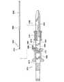
図1〜図10を参照すると、縫合糸12を連続的に付けるための内視鏡的縫合器械10が開示されている。本明細書全体を通じて用いられる「縫合糸」という用語は、天然フィラメントで作られているにせよ、合成またはポリマーフィラメントで作られているにせよ、あるいは金属製ワイヤフィラメントで作られているにせよ、いずれにせよ、種々の柔軟な固定用フィラメントを意味するようになっている。 With reference to FIGS. 1-10, an
本発明の縫合器械は、特に、内視鏡的胃縮小手技を行う際に用いられるよう構成されているが、当業者であればこの器械を本発明の精神から逸脱することなく、多種多様な用途に使用できることは確実に理解されよう。特に、本発明の縫合器械は、例えば経口的に患者の生まれつきの開口中に挿入可能な寸法形状になっており、したがって、直径が約3mm〜約24mmの開口中に挿入可能な寸法形状になっている。本発明の縫合器械は、特に、患者の生まれつき備わった開口中に挿入可能に構成されているが、本発明の縫合器械は、トロカール中に腹腔鏡的に挿入可能な寸法形状になっていてもよく、したがって、直径が約3mm〜約18mmの開口中に挿入可能な寸法形状になっていてもよい。 The suture instrument of the present invention is particularly configured for use in performing endoscopic gastric reduction procedures, but those skilled in the art will recognize a variety of different instruments without departing from the spirit of the present invention. It will be appreciated that it can be used for applications. In particular, the suturing device of the present invention is dimensioned to be insertable, for example, orally into a patient's native opening, and thus dimensioned to be insertable into an opening having a diameter of about 3 mm to about 24 mm. ing. The suturing instrument of the present invention is particularly configured to be inserted into a patient's natural opening, but the suturing instrument of the present invention may be sized to be laparoscopically inserted into a trocar. It may therefore be dimensioned to be insertable into an opening having a diameter of about 3 mm to about 18 mm.
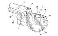
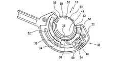
縫合器械10は、市販の内視鏡または他の支持構造部材18の遠位端部16にその作動を可能にすると共に真空を生じさせることができるような仕方で取り付け可能な寸法形状の縫合本体14を有している。このことを念頭に置いて、縫合本体14は、当業者には知られている公知の取り付け構造を用いて内視鏡18に固定されている。 The
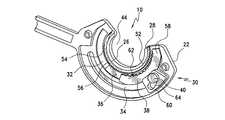
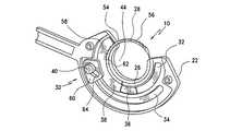
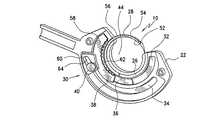
縫合本体14は、縫合糸ハウジング24をつくりだすよう互いに固定された第1のハウジング部材20と第2のハウジング部材22で構成され、本発明の器械10の機能的コンポーネントは、本発明に従って運動可能にこの縫合糸ハウジング内に収納されている。縫合糸ハウジング24は、内側の第1の軌道26を有し、針28が、駆動組立体30の制御下で所定の連続した円形経路に沿って移動可能にこの第1の軌道内に位置決めされている。 The
本発明の縫合器械は、連続円形経路に沿う針の並進運動を可能にするものとして好ましい実施形態に従って開示されるが、本発明の根底をなす技術的思想の多くは、針を必ずしも連続した円形経路に沿ってだけでなく、弧状経路に沿って移動させるに過ぎないシステムに適用できることが想定される。 While the suturing instrument of the present invention is disclosed in accordance with a preferred embodiment as allowing translation of the needle along a continuous circular path, many of the underlying technical ideas of the present invention do not necessarily require a continuous circular needle. It is envisaged that the present invention is applicable not only along a path but also to a system that only moves along an arcuate path.
駆動組立体30は、内側の第1の軌道26に沿って位置決めされた第2および第3の軌道32,34内に支持されている。駆動組立体30は、軸方向運動を利用して針28をその連続した円形経路に沿って移動させる。駆動組立体30は、概して、第2の軌道32に沿って静的に取り付けられた摩擦プレート36、およびピン40が外側の第3の軌道34に沿って動いている間、第2の軌道32に沿って動く摩擦カム作用部材38で構成されている。駆動ケーブル42が、以下に詳細に説明するような仕方で、ピン40の作動を制御するためにピン40に結合されている。駆動ケーブル42は、取っ手(例えば、図47〜図51に示されている)によって駆動組立体30を動かすことができるよう作動される。好ましい取っ手を以下に開示するが、本発明の精神から逸脱することなく、駆動ケーブルの作動にあたり種々の取っ手構造体を利用できることが想定される。 The
以下に詳細に説明する本発明の縫合器械10の作用に基づいて明らかになる理由で、縫合本体14は、組織を縫合中に位置決めする中央開口部44を備えた実質的にC字形のものである。縫合本体14がC字形になっていることにより、針28は、その作動中、円形経路に沿って動き、中央開口部で位置決めされた組織を通過することができる。 For reasons that will become apparent based on the operation of the
図1および図2を参照すると、好ましい実施形態に従って、本発明の内視鏡的縫合器械10は、クランプ17により市販の内視鏡18に取り付けられている。大まかに上述したように、また、以下に詳細に説明するように、縫合器械10を本発明の精神から逸脱することなく種々の仕方で内視鏡18に固定することができる。縫合器械10は、ユーザが針28および術野の視認性を維持すると共に経口挿入(縫合器械10が胃外科手技に用いられる場合)を助けるよう小さな断面を生じさせることができるような仕方で差し向けられる。 With reference to FIGS. 1 and 2, according to a preferred embodiment, the
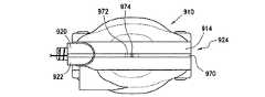
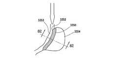
真空チャンバ46が、本発明の縫合器械10の縫合本体14を包囲すると共に(あるいは)違ったやり方で収納する。これは、縫合本体14が嵌め込まれるキャビティ48を画定している。真空チャンバ46は、真空ライン50に結合され、この真空ラインは、内視鏡18の作業チャネル内ではなく、内視鏡18と縦に並んで結合されており、したがって、真空が真空チャンバ46により画定されたキャビティ48ならびに縫合本体14の中央開口部44内に作られるようになっている。このように、真空を発生させることにより、隣接の組織は、縫合本体14の中央開口部44内に吸い込まれる。 A
大まかに上述したように、本発明の縫合器械10は、組織を縫合のための位置に引き込む手際を向上させるよう設計された真空チャンバ46を備えている。真空チャンバ46は、適用された真空の制御下で組織壁を真空チャンバ46および特に縫合本体14の中央開口部44内に引き込みやすくするような寸法形状になっている。真空チャンバ46および中央開口部44内にいったん引き込まれると、組織は、縫合本体14がステッチを作りながら針28が組織に通されているとき、組織は、これらの中に保持される。真空チャンバ46の所要のサイズは、縫合される組織の厚さに基づいている。所望の厚さの組織を引くのに必要な真空は、組織の厚さと真空チャンバ46のサイズの両方に比例する。 As generally described above, the
その結果、本発明の真空チャンバ46は、真空チャンバ46を胃の中に通すのに大きすぎるようにしないで、仕事を達成するのに必要な真空を最小限に抑えるようそのサイズを増大させようとするものである。本発明の真空チャンバ46が病院または他の医療施設で提供される真空圧力で所望の吸引力を達成することができることは、種々の病院ならびに種々の手術室内で使える真空源の大きさが大幅にまちまちであることを考慮すると、特に重要である。 As a result, the
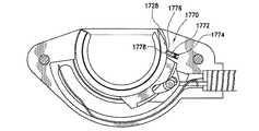
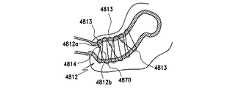
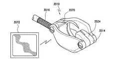
このことを念頭に置き、図11および図12(図中、同様の参照符号は、同様の部分のために用いられている)に示すような本発明の好ましい実施形態によれば、真空チャンバ146は、弾性エラストマーで構成されている。この真空チャンバは、その形態がカップ状であり、一般に、内壁170および外壁172を有している。真空チャンバ146の内壁170は、好ましくは、真空チャンバ146が吸引力下で組織をこれに吸い付けた状態を保持することができる性能を一段と向上させるために突起174、例えばリブおよび(または)フック(図12に示されている)を備える。これら突起174は、真空が真空チャンバ146に適用されたとき、組織をピン止めする掴み表面となる。突起174はまた、真空の保持パワーを増大させ、それにより必要な真空の量を最小限に抑える。 With this in mind, according to a preferred embodiment of the invention as shown in FIGS. 11 and 12 (wherein like reference numerals are used for like parts), the
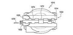
好ましい実施形態によれば、真空チャンバ146は、縫合本体114の機能コンポーネントを収納しまたは包囲する仕方で縫合本体114の互いに反対側の側部に固定された第1の真空チャンバ部材176および第2の真空チャンバ部材178で構成されている。第1の真空チャンバ部材176と第2の真空チャンバ部材178は、互いに鏡像関係にあり、真空を生じさせるために縫合本体114を包囲した空間を画定している。好ましい実施形態によれば、第1の真空チャンバ部材176および第2の真空チャンバ部材178は、縫合本体114が位置決めされるカップ状の空間を画定している。 According to a preferred embodiment, the
第1および第2の真空チャンバ部材176,178は各々、半円形上縁部184および凹状下方部分186を有している。したがって、第1および第2の真空チャンバ部材176,178を縫合本体114の互いに反対側の側部に沿って固定すると、カップ状空間が、縫合本体114の周りに画定される。カップ状空間は、組織を縫合本体114の中央開口部144内に確実にかつ効率的に吸い込むように真空によって得られた吸引力が拘束される密閉空間となる。 The first and second
真空チャンバ146の第1および第2の真空チャンバ部材176,178は、エラストマー、例えばウレタン、アジプレン(adiprene)またはサントプレン(santoprene)から作られる。真空チャンバ146は、その膨張および収縮を可能にするよう設計されている。膨張可能な真空チャンバ146を設けることにより、チャンバサイズは、最大になって真空適用中の組織包含を増大させると共に縫合器械110の挿入中、真空チャンバ146のサイズを減少させることができる。具体的に説明すると、真空チャンバ146が膨張したり収縮したりすることができることにより、縫合器械110の経口通過が容易になる一方で、同様に、組織吸引中、真空チャンバ146のサイズが最適化される。 The first and second
当業者であれば理解されるように、縫合器械110の経口通過が必要であることにより、縫合器械110の寸法に最終限度が定められ、したがって、本発明に従って組織を捕捉するように導入できる真空チャンバ146の寸法形状に最終限度が定められる。真空チャンバ146が大きければ大きいほど、縫合器械110の1回の操作で捕捉できる組織の「食い付き(bite)」が大きくなる。このことを念頭に置いて、上述したように、真空チャンバ146は、真空チャンバを挿入中折り畳むことができ、次に、真空チャンバを完全に挿入した後にその元の形状に「スプリング」バックすることができるようにするエラストマーで作られる。 As will be appreciated by those skilled in the art, the need for an oral passage of the
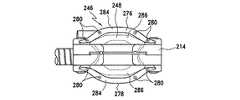
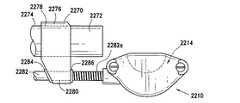
変形実施形態によれば、図13および図14を参照すると、真空チャンバ246の膨張は、真空チャンバ246により画定されたキャビティ248のあらかじめ定められた曲げ箇所のところに一体ヒンジ(living hinges)280を設けることによって一段と容易になる。これにより、真空チャンバ246は、非弾性プラスチックを含む多種多様な材料で構成することができる。というのは、一体ヒンジ280により、より剛性の高い構造体が弾性的に曲げられるのではなく「折り畳む」ことができるからである。特に、先の実施形態を参照すると、真空チャンバ246は、第1の真空チャンバ部材276および第2の真空チャンバ部材278で構成されている。第1の真空チャンバ部材276と第2の真空チャンバ部材278は、互いに鏡像関係にあり、これら真空チャンバ部材は各々、半円形上方部分284および凹状下方部分286を有している。その結果、第1および第2の真空チャンバ部材276,278は、本発明の真空チャンバ246を形成するよう縫合本体214の互いに反対側の側部に結合され、この真空チャンバは、先の実施形態に関して上述したリブおよび(または)フックを同様に有するのがよい。 According to an alternative embodiment, referring to FIGS. 13 and 14, the expansion of the
好ましい実施形態によれば、第1および第2の真空チャンバ部材276,278は、半剛性材料で構成され、したがって、これら真空チャンバ部材はそれぞれ、その膨張および収縮を可能にする一体ヒンジ280を有する。一体ヒンジ280は、第1および第2の真空チャンバ部材276,278のあらかじめ定められた曲げ箇所のところにこれらの折り畳みを最適化する仕方で位置決めされている。一体ヒンジ280により、第1の真空チャンバ部材276と第2の真空チャンバ部材278を本発明に従って互いに対して動かしているときに、真空チャンバ246の制御された膨張および収縮が可能である。したがって、用いられた場合、真空チャンバを通過させる経口空間よりも最終的には大きな真空チャンバ246を通過させることができる。 According to a preferred embodiment, the first and second
当業者であれば理解されるように、任意の種類の組織、任意の厚さの組織を受け入れるように構成されていて、ユーザが食い付きサイズ(即ち、縫合糸を通す組織の広がり)を調節することができるようにする真空チャンバおよび中央開口部をつくることが望ましい。この目的のため、真空チャンバおよび中央開口部の有効サイズの調節のための種々の実施形態を開発しており、これら実施形態を本明細書に開示する。これら実施形態はまた、種々の厚さの組織、種々の種類の組織および縫合糸ひと縫い当たりの可変組織食い付きに用いることができるよう真空チャンバの長さ方向および側方調節、ならびに中央開口部および真空チャンバの深さ調節を可能にする。このように、外科医は、組織食い付きの深さの調節を可能にするよう真空チャンバ/中央開口部の有効深さ、有効幅および(または)有効長さを容易に調節することができ、それにより、組織を通る針の経路深さ(即ち、全厚または部分的厚さ)を制御する。また、調節が可能であることにより、同一の縫合器械を多くの組織の種類および厚さに使用することができる。真空チャンバおよび中央開口部内に吸い込み可能な組織の最大量を制限しながら、本発明の技術はまた、所定のかつ制御された量の組織が真空チャンバおよび中央開口部内に吸い込まれることを確実にするよう利用できる。 As will be appreciated by those skilled in the art, it is configured to accept any type of tissue, any thickness of tissue, and allows the user to adjust the bite size (ie, the extent of tissue passing through the suture). It is desirable to create a vacuum chamber and a central opening that allow it to do so. For this purpose, various embodiments have been developed for adjustment of the effective size of the vacuum chamber and central opening, and these embodiments are disclosed herein. These embodiments also include lengthwise and lateral adjustment of the vacuum chamber, as well as a central opening so that it can be used for varying thickness tissue, different types of tissue and variable tissue bite per suture. And allows adjustment of the depth of the vacuum chamber. In this way, the surgeon can easily adjust the effective depth, effective width and / or effective length of the vacuum chamber / central opening to allow adjustment of the depth of tissue bite, Controls the path depth of the needle through the tissue (ie, full thickness or partial thickness). The ability to adjust also allows the same suturing instrument to be used for many tissue types and thicknesses. While limiting the maximum amount of tissue that can be sucked into the vacuum chamber and central opening, the technique of the present invention also ensures that a predetermined and controlled amount of tissue is sucked into the vacuum chamber and central opening. As available.
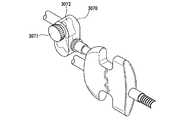
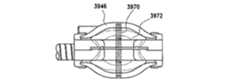
好ましい実施形態によれば、図89、図90および図91を参照すると、調節は、調節ねじ3970を真空チャンバ3946のベース3972内に設けることにより達成される。ねじ3970はそれぞれ、真空チャンバ3946のベース3972内に設けられていて、真空チャンバ3946を所望の方向に膨張させまたは収縮させるねじ3970を調節することにより真空チャンバ3946の長さ方向または側方調節を可能にする。 According to a preferred embodiment, referring to FIGS. 89, 90 and 91, adjustment is achieved by providing an
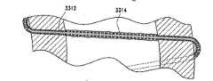
別の実施形態によれば、図88を参照すると、真空チャンバ4046の有効ベース、および中央開口部4044を持ち上げて真空チャンバ4046および中央開口部4044の有効深さを制御するためにワイヤ4070が用いられている。このワイヤ4070は、折り曲げ間隔保持ワイヤであり、このワイヤは、更に折り曲げ可能でありまたは真っ直ぐになることができ、組織が中央開口部4044および真空チャンバ4046により画定されたキャビティに入ることができる深さを効果的に減少させる。ばねワイヤ4070が真っ直ぐになればなるほど、キャビティの有効底部をそれだけ一層高く設定することができる。それにより、ばねワイヤ4070は、中央開口部4044内への組織の深い入り込み(即ち、ばねワイヤ4070により作られたバリヤを越える入り込み)を阻止する。ワイヤ4070のたるみは、縫合本体4014内に設けられ、ワイヤ4070を作動させるねじ部材4072により制御される。 According to another embodiment, referring to FIG. 88, a
図93を参照すると、別の実施形態にしたがって、真空チャンバ4148の有効長さを調節するのに締め付けケーブル4170が用いられている。具体的に言えば、締め付けケーブル4170をその自由端部4172,4174が真空チャンバ4146の近位端部のところで出た状態で真空チャンバ4146の外周部の周りに通す。したがって、自由端部4172,4174に張力を加えて真空チャンバ4146の長さを短くし、同様に、真空チャンバ4146の壁がこれらの非付勢位置に膨張することができるようにすることにより真空チャンバ4146の長さを増大させたい場合に、自由端部を解除できる。 Referring to FIG. 93, a clamping
上述したように、ハウジング24は、中央開口部44内に引き込まれた組織への縫合糸12付けの際に用いられる針28を収納している。縫合糸12は、針28の近位端部、即ち切れ味の鈍い端部に固定され、針28を本明細書において説明するように本発明に従って作動させると、組織中に引き込まれる。好ましい実施形態によれば、針28は、所定の連続円形経路に沿って回転するよう湾曲しており、この針は、240°の弧に沿って延び、120°の開口部をつくりだしている。しかしながら、当業者であれば理解されるように、開口部は様々であってよく、例えば、140°の開口部を提供する針を用いることが想定される。 As described above, the
針28は、針28により画定される弧の内面に沿って位置する内面52、および針28により画定される弧の外側の表面に沿って位置する外面54を有している。一連の切欠き56が、針28の外面54に切り込み形成されている。以下の説明に基づいて理解されるように、切欠き56は、針28を掴み、駆動し、そして放す際に駆動組立体30により使用可能な寸法形状になっている。針の外面に沿って位置する切欠きは、本発明の好ましい実施形態に従って使用できるよう開示されるが、針は、駆動組立体が針を前方に駆動するために針の実質的に滑らかな外面を単に掴むように切欠きを備えていなくてもよいことが想定される。
駆動組立体30の作動、および針28の運動を図3〜図10を参照して説明するが、これらの図では、ハウジング24の一方の半部は取り外されていて、本発明の縫合器械10の内部コンポーネントが露出している。駆動ケーブル42(図3に示されている)は、ピン40に剛性的に取り付けられている。以下に詳細に説明するように、駆動ケーブル42、ピン40および摩擦カム作用部材38は、針28をその円形経路に沿って動かすために針28に係合したりこれから外れるよう延ばされたり引っ込められたりする。駆動ケーブル42は、ハウジング24内で湾曲すると共に内視鏡18と一緒に撓むのに十分可撓性であるが、摩擦カム作用部材38をその初期駆動段階(図4参照)に駆動するよう圧縮されるのに十分剛性である。 Operation of the
摩擦カム作用部材38は、弧状係合部材58およびカム作用部材60で構成され、これら部材は、針28に選択的に係合するよう係合部材58の位置を制御するようピン40と関連して働く。係合部材58は、針28を時計回りの方向に駆動するが、摩擦カム作用部材38、即ち、係合部材58とカム作用部材60の両方を初期駆動段階に向かって反時計回りの方向に動かすときに、針28の自由運動を可能にするよう針28に係合可能な寸法形状になった内部切欠き62を備えている。 The
摩擦カム作用部材38の係合部材58は、針28に半径方向に近づけたりこれから遠ざかってハウジング24内で並進すると共にハウジング24により定められた弧に沿って正確に時計回りに並進したり反時計回りに並進するよう設計されている。これは、カム作用部材60、ピン40および係合部材58相互間の相互作用により提供されるカム作用によって達成される。カム作用部材60の半径方向位置をピン40とのその相互作用に基づいて変更するときに、係合部材58が針28に係合したりこれから離脱したりするよう動くように、カム作用部材60は、係合部材58に剛性的に結合されている。変形実施形態に従って以下に説明するように、摩擦カム作用部材38を針28に押し付けるのにばね要素を用いてもよいことが想定される。 The
具体的に説明すると、駆動ケーブル42を圧縮して(即ち、駆動ケーブル42を縫合器械10の作動から遠位側に押し離して)摩擦カム作用部材38を反時計回りの方向に動かすと、ピン40は、カム作用部材60に形成されたスロット64内でスライドし、係合部材58およびカム作用部材60を反時計回りにかつ針28から見て外方へ動かす。摩擦プレート36は、摩擦カム作用部材38をこの反時計回りの方向に動かしているときに係合部材58を針28から外方へ動かすのを助ける。 Specifically, when the
摩擦カム作用部材38が図4に示すようなその初期駆動位置にある状態で、張力を駆動ケーブル42に加え(即ち、駆動ケーブル42を縫合器械10の作動に向かって近位側に引き)最終的にピン40に加えると、ピン40は、カム作用部材60に係合し、摩擦カム作用部材38および特に係合部材58をカム作用部材60(図5参照)内におけるピン40とスロット64の相互作用に起因するカム作用により内方に移動して針28の外面54に接触させる。張力を駆動ケーブル42に連続的に加えると、係合部材58の内面に沿って形成された切欠き62は、針28の外面54に切り込み形成された切欠き56に嵌まって針28を時計回りに回転させ、ついには、ピン40が軌道34の限度に達するようになり、手順は、あらゆる点で始まる必要がある(図6参照)。 With the
図6に示すように行程の限度に達すると、オペレータは、駆動ケーブル42を圧縮し、ピン40がスロット64内でスライドするときのカム作用部材60のスロット64内でのピン40の相互作用に起因して得られるカム特徴により係合部材58が針28から外れ、係合部材58およびカム作用部材60が、外方にかつ反時計回りの方向に動くようになる(図7参照)。駆動ケーブル42に及ぼされる圧縮は、摩擦カム作用部材38が反時計回りに動いてハウジング24の反対側の端に到達する(図8参照)まで続けられる。次に、張力をもう一度加えて針28を反時計回りの方向に動かし、かかる手順を、針が360°動くまで続けられる(図9および図10参照)。 When the stroke limit is reached, as shown in FIG. 6, the operator compresses the
大まかに上述したように、本発明の駆動組立体30は、針28を非常に制御されると共に効率的な仕方でその円形経路に沿って駆動することができる。図15を参照すると、本発明の駆動組立体330の機能性は、摩擦カム作用部材338を設けることにより高められ、かかる駆動組立体は、針328を摩擦手段によりその経路に沿って引く際に針328を駆動する。摩擦カム作用部材338の摩擦インターフェイス358の接触面は、本発明に従って針328を滑らかにかつ確実に動かすよう針328とのその摩擦関係を高めるよう作られている。 As described generally above, the
摩擦カム作用部材338と針328との間の相互作用は、板ばね370を設けることにより高められる。板ばね370は、縫合器械310の縫合糸ハウジング324内に延び、この板ばねは、摩擦カム作用部材338を針328に接触させるための針328の作動中、摩擦カム作用部材338に接触するよう差し向けられている。板ばね370は、摩擦カム作用部材338の近位側に設けられた片持ち取り付け式ばね部材である。摩擦カム作用部材338を遠位側に押しやると、板ばね370は、係合力を増大させ、摩擦カム作用部材338を半径方向に更に遠くに変位させる。当業者であれば確実に理解されるように、ばね構造体が、本発明の好ましい実施形態に従って開示され、本発明の精神から逸脱することなく、他のばね構造体を用いることができる。 The interaction between the
変形実施形態によれば、図16を参照すると、上述した滑らかな摩擦カム作用部材338に代えて、歯付き摩擦カム作用部材438を用いてもよい。この実施形態によれば、摩擦カム作用部材438の摩擦インターフェイス458の接触面は、歯472を備え、これら歯は、針428の外面に沿って形成された歯474に係合するような寸法形状になっており、かかる歯474は、歯472と同様に形作られている。このように、摩擦カム作用部材438の摩擦インターフェイス458に沿って設けられた歯472は、針428に切断形成された歯474と係合し、針428を引っ張ったときにその駆動経路に沿って針428を引きずる。先の実施形態の場合と同様、摩擦カム作用部材438と針428との間の相互作用は、板ばね470を設けることにより高められる。板ばね470は、縫合器械410の縫合糸ハウジング424内に延び、この板ばねは、摩擦カム作用部材438を針428に接触させるための針428の作動中、摩擦カム作用部材438に接触するよう差し向けられている。 According to a modified embodiment, referring to FIG. 16, a toothed friction
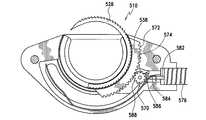
変形実施形態によれば、図17を参照すると、針528を駆動する際に用いられる摩擦カム作用部材538(これが、図15に示すような滑らかな摩擦カム作用部材338であれ、図16に示すような歯付き摩擦カム作用部材438であれ、いずれにせよ)の運動もまた、摩擦カム作用部材538の裏側574に設けられた歯572と係合するスプロケット歯車570を用いて、針528を直線引張りシステムによって得られる同一の運動により駆動することにより達成できる。かかる歯車装置は、駆動ケーブル582に沿い、かつ縫合器械510を貫通する縫合器械510の長さ方向軸線と実質的に整列した第1の軸線回りの回転運動を、縫合器械510の長さ方向軸線に実質的に垂直な中心軸線を有する弧状経路沿いの針528の回転運動に変換することができる。この実施形態によれば、スプロケット歯車570は、直線引張りシステムに取って代わった取っ手(図示せず)内の回転部材に結合された回転ケーブル駆動システム576により回転する。この実施形態によれば、ケーブルの回転運動(器械のシャフトの長さ方向軸線回りの回転)は、針528を直接その円形経路に沿って駆動し、または歯付き摩擦カム作用部材538をその経路中で駆動する回転運動(装置シャフトの長さ方向軸線に垂直な回転)に変換される。 According to an alternative embodiment, referring to FIG. 17, the
具体的に説明すると、駆動ケーブル582は、器械510の長さ方向軸線に実質的に平行な軸線回りに回転可能に設計されている。駆動ケーブル582の遠位端部584は、平歯車586を備え、この平歯車は、駆動ケーブル582の遠位端部584のところの平歯車586と摩擦カム作用部材538の歯付き接触面574との間に設けられた同様な平歯車588に結合されている。その結果、駆動ケーブル582を回転させると、平歯車586が回転し、それにより摩擦カム作用部材538が運動する。すると、摩擦カム作用部材538の運動により、針528は、所望の弧状経路で動く。摩擦カム作用部材538は、上述した実施形態と類似した仕方で針528に係合したりこれから外れたりするので、針528の運動は、回転ケーブルシステムの回転を交互に逆にすることにより達成される。前方回転は、摩擦カム作用部材538にカム作用を及ぼして係合させ、針528を駆動する仕方で摩擦カム作用部材538を反時計回りに駆動する。駆動ケーブル582の逆回転により、摩擦カム作用部材538が針528から外れ、摩擦カム作用部材538が時計回りに回転し、それにより摩擦カム作用部材は、次の駆動運動のために再設定される。 Specifically, the
摩擦カム作用部材の設計とは無関係に、本発明の好ましい実施形態に従って用いられる駆動機構体は、単一の器械挿入中、多数の組織穿通が可能な縫合糸を通すための回転針駆動システムを提供する。上述したように、本発明の好ましい実施形態によれば、これは、摩擦カム作用部材が歯の係合または摩擦結合によって針を前進させ、本発明に従って用いられる針と縫合糸の両方のサイズの変更を可能にする針の前進を可能にすることにより達成される。 Regardless of the design of the friction camming member, the drive mechanism used in accordance with the preferred embodiment of the present invention provides a rotating needle drive system for threading multiple tissue piercing sutures during a single instrument insertion. provide. As mentioned above, according to a preferred embodiment of the present invention, this is because the friction camming member advances the needle by tooth engagement or frictional coupling and is sized for both the needle and suture used in accordance with the present invention. This is accomplished by allowing advancement of the needle to allow change.
図18および図19を参照して2つの後退防止構造体を開示する。これら後退防止構造体は、針が一方向にしか通らないように針の運動を制御する。これにより、針が図6に示すような行程位置のその端(または限度)と図8に示すようなその初期駆動位置との間で動く際に、針が後退して摩擦カム作用部材の作動行程相互間から出るのが阻止される。より具体的に説明すると、本発明の縫合器械の針は、弧状経路に沿う所定の第1の方向に動くよう設計され、逆の第2の方向への運動は、望ましくない。したがって、本発明の後退防止構造体は、第2の方向における針の運動を阻止する一方で、第1の方向における針の自由運動を可能にする。 Two anti-retraction structures are disclosed with reference to FIGS. These anti-retraction structures control the movement of the needle so that the needle passes only in one direction. Thus, when the needle moves between its end (or limit) of the stroke position as shown in FIG. 6 and its initial drive position as shown in FIG. It is prevented from leaving between the processes. More specifically, the needle of the suture instrument of the present invention is designed to move in a predetermined first direction along an arcuate path, and movement in the opposite second direction is undesirable. Accordingly, the anti-retraction structure of the present invention allows free movement of the needle in the first direction while preventing needle movement in the second direction.
具体的に説明すると、図18を参照して説明する好ましい実施形態によれば、摩擦後退防止装置670が、針628の望ましくない後退を阻止する仕方で針628に接触できるよう針628の経路の前方端に沿って固定されている。摩擦後退防止装置670は、第1の端部674および第2の端部676を有するレバーアーム672である。レバーアーム672の第1の端部674は、縫合器械610の縫合本体614に旋回可能に固定されている。レバーアーム672の第2の端部676は、針628の接触面に向かって延びてこれに接触している。レバーアーム672は、針628を図18に示すように反時計回りの方向に動かすと、レバーアーム672が針628の外面上をスライドし、針628が自由に回転できるよう差し向けられている。 Specifically, according to the preferred embodiment described with reference to FIG. 18, the anti-friction back-up
しかしながら、針628が図18に示すように時計回りの方向に回転しようとした場合、レバーアーム672の第2の端部676は、針628の時計回りの回転を停止させる仕方で針628の外面に摩擦係合する。これは、例えばラチェット機構と同様な針628の運動に対する摩擦による妨害を生じさせるレバーアーム672の向きの結果である。このことを念頭に置いて、レバーアーム672は、針を時計回りに回転させるにせよ、反時計回りの方向に回転させるにせよ、いずれにせよ、針628の外面との係合状態を維持するよう付勢される。 However, if the
変形実施形態によれば、図19を参照すると、縫合本体714は、針728の外面に形成された凹部772に嵌まり込むような寸法形状の一体形ばね付勢ラッチ770を備えている。このことを念頭に置いて、ラッチ770と凹部772は、一方向における針728の実質的に自由な回転を可能にする一方で、逆方向における針728の回転を阻止するような寸法形状になっている。 According to an alternative embodiment, referring to FIG. 19, the
針が配備中組織内でつかえて動かなくなる場合があり得るので、縫合器械と針の両方の非常時取り出しを可能にするよう針を縫合器械から自由にすることが必要になる場合がある。このことを念頭に置いて、以下に提供する種々の実施形態に関し、針がつかえて動かなくなり、解除を必要とする場合に針を自由にする技術が開発されている。一般に、以下に説明する実施形態は、縫合器械の縫合糸ハウジングを分離しまたは開いて針を解除し、縫合器械を取り出すことができるようにする互いに異なる方法である。このように針を解除することには、次に針をそのつかえ位置から取り出す必要があるが、縫合器械は、針の解除に基づいてもはや組織に引っ掛けられていないので、縫合器械の残部の取り出しが可能であろう。 Since the needle may become stuck in the tissue during deployment, it may be necessary to free the needle from the suturing instrument to allow emergency removal of both the suturing instrument and the needle. With this in mind, a technique has been developed for the various embodiments provided below that frees the needle when it is stuck and needs to be released. In general, the embodiments described below are different ways to separate or open the suture housing of the suture instrument to release the needle and allow the suture instrument to be removed. To release the needle in this way, it is then necessary to remove the needle from its gripping position, but the suture instrument is no longer hooked to the tissue based on the release of the needle, so the remainder of the suture instrument is removed. Would be possible.
以下に開示する種々の実施形態によれば、外科用縫合器械は、縫合糸ハウジング、および弧状経路に沿って運動可能に縫合糸ハウジング内に設けられた針を有する。縫合器械は、針に作動可能に関連していて、縫合糸が固定された状態の針を、縫合糸を組織に付けやすくする仕方で弧状経路に沿って運動させるのを制御する駆動組立体を更に有する。縫合糸ハウジングは、開放位置および閉鎖位置を有し、針を縫合糸ハウジングが開放位置にあるとき縫合糸ハウジングから取り出すことができる。 According to various embodiments disclosed below, a surgical suturing instrument has a suture housing and a needle disposed within the suture housing that is movable along an arcuate path. The suturing instrument is operably associated with the needle and includes a drive assembly that controls movement of the secured needle along the arcuate path in a manner that facilitates attaching the suture to tissue. Also have. The suture housing has an open position and a closed position, and the needle can be removed from the suture housing when the suture housing is in the open position.
種々の実施形態は、針が万一前進することができず、縫合器械を取り出す必要がある場合、縫合糸ハウジングを選択的に開放することができる制御された開放機構体をユーザに提供する。以下に詳細に説明するように、これは、押しつぶし可能な結合機構体を作動させたときに開くばね付勢ヒンジ止めクラムシェル形縫合本体を用いるか、縫合本体の2つの半部を一緒に保持する取り外し可能なピン/ケーブル機構体を用いるか、あるいは、本体からの取り出しのために再閉鎖できる開放可能な縫合糸配備システムを用いることにより達成される。 Various embodiments provide the user with a controlled release mechanism that can selectively open the suture housing if the needle cannot be advanced and the suture instrument needs to be removed. As will be described in detail below, this can be achieved by using a spring-biased hinged clamshell suture body that opens when the collapsible coupling mechanism is actuated, or holding the two halves of the suture body together This can be accomplished by using a removable pin / cable mechanism that relies on or a releasable suture deployment system that can be reclosed for removal from the body.
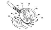
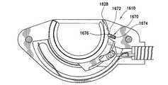
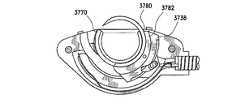
第1の実施形態によれば、図20〜図22を参照すると、上記において詳細に説明したように縫合本体814は、縫合糸ハウジング824を構成する第1のハウジング部材820および第2のハウジング部材822で構成されている。カムピンセット(カムピンの組)870が、第1のハウジング部材820と第2のハウジング部材822を互いにロックするが、つかえて動かなくなった針828を取り出すために第1のハウジング部材820と第2のハウジング部材822を分離することが望ましい場合、カムピンセット870を第2のハウジング部材822から取り外すことができる。 According to the first embodiment, referring to FIGS. 20-22, as described in detail above, the
より具体的に説明すると、第1のハウジング部材820と第2のハウジング部材822は、これらの一端部に沿って符号872のところでヒンジ止めされ、カムピンセット870は、第1のハウジング部材820と第2のハウジング部材822を互いにしっかりと保持するようにヒンジ872と逆の仕方で位置決めされている。しかしながら、カムピンセット870を取り外しまたはこれとは違ったやり方で第2のハウジング部材822とのそのロック位置から外すと、第1および第2のハウジング部材820,822は、互いに離れてヒンジ872を中心として自由に旋回することができる。縫合糸ハウジング824の開放は、カムピンセット870の取り外し時に縫合糸ハウジング824の開放を促進するばね874をヒンジ872内に設けることにより一段と容易になる。 More specifically, the
カムピンセット870の作動は、カムピンセット870の制御されたロックおよび解除を可能にするよう相互作用する解除部材876を用いることにより達成される。具体的には、解除部材876は、一連の干渉部材878を有し、これら干渉部材は、カムピンセット870のヘッド880を第2のハウジング部材822に形成された凹部882(図21参照)内に保持するようかかるヘッド880と相互作用する。第1のハウジング部材820と第2のハウジング部材822を分離することが望ましい場合、例えばユーザにより作動可能に延びるケーブル884により解除部材876をずらして干渉部材878を動かし、それによりカムピンセット870が第2のハウジング部材822内から動くことができるようにする(図22参照)。 Actuation of the cam tweezers 870 is accomplished by using a
別の実施形態によれば、図23および図24を参照すると、ティアーストリップ(tear strip)970が開示されている。先の実施形態の場合と同様、縫合本体914は、縫合糸ハウジング924を構成する第1のハウジング部材920および第2のハウジング部材922で構成されている。第1のハウジング部材920と第2のハウジング部材922は、これらの一端部に沿って符号972のところでヒンジ止めされ、ばね974が、第1および第2のハウジング部材920,922を開放向きに付勢している。 According to another embodiment, referring to FIGS. 23 and 24, a
ティアーストリップ970は、第1および第2のハウジング部材920,922の中心線を通って位置決めされている。好ましい実施形態によれば、ティアーストリップ970は、接着剤か他の機械的な脆弱なプラスチック結合特徴部かのいずれかにより第1および第2のハウジング部材920,922に固定されている。引っ張ると、ティアーストリップ970は、第1のハウジング部材920と第2のハウジング部材922との間の中心から「裂け」出し、縫合器械910が開放状態になることができる。ティアーストリップ970は、真っ直ぐな接着剤または成型ストリップであってもよく、あるいは、ティアーストリップ970は、最も遠位側の端部の一部として、ティアーストリップを取り外すと半部を一段と広げて開くカム作用特徴部(以下に説明する)を有してもよい。 The
図25および図26を参照して別の実施形態を開示する。この実施形態では、つかえて動かなくなった針を縫合本体1014から解除するために縫合本体1014の選択的な開放を容易にする引きケーブル1074を用いている。この実施形態によれば、縫合本体1014は、縫合糸ハウジング1024を構成する第1のハウジング部材1020および第2のハウジング部材1022で構成されている。第1のハウジング部材1020と第2のハウジング部材1022は、これらの一端部に沿って符号1072のところでヒンジ止めされている(または、別々の関連性の無い半部である)。第1および第2のハウジング部材1020,1022は、これらの開放端部に沿ってレーシング(lacing) ループ1074を更に備えている。レーシングループ1074は、第1のハウジング部材1020と第2のハウジング部材1022を互いに保持する仕方で引きケーブル1070を挿通させることができるような寸法形状になっている。 Another embodiment is disclosed with reference to FIGS. In this embodiment, a
具体的に説明すると、引きケーブル1070をドアのヒンジに非常によく似たように第1および第2のハウジング部材1020,1022に交互に配置されたレーシングループ1074に通す。引きケーブル1070が第1および第2のハウジング部材1020,1022の周囲にぐるりと存在している限り、第1および第2のハウジング部材1020,1022は、互いに保持され、針1028は、この中に保持される。しかしながら、針1028を取り出しまたは違ったやり方で縫合器械1010の縫合本体1014を開くことが望ましい場合、引きケーブル1070を引き、それにより引きケーブルをレーシングループ1074から引き出し、第1のハウジング部材1020と第2のハウジング部材1022を互いに解除する。第1および第2のハウジング部材1020,1022が解除された状態で、ばね付勢ヒンジ1072は、第1および第2のハウジング部材1020,1022をヒンジ1072に沿って旋回させることにより第1のハウジング部材1020と第2のハウジング部材1022を引き離す。 Specifically, the
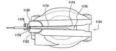
図27および図28を参照してスプレッダプレート1170の実施形態を開示する。これは、図23および図24を参照して上述したティアーストリップの設計上の変形例である。この実施形態によれば、中央連結部材1172は、2つのハウジング部材1120,1122を互いに結合したり解除したりするだけでなく、中央連結部材1172の遠位端部に設けられたカム作用部材1174を有し、このカム作用部材は、これをシステム中に引っ張ると、第1のハウジング部材1120と第2のハウジング部材1122がただ自由にばらばらになることができるようにするのではなく、これらハウジング部材を実際にカム作用により離す。 An embodiment of a
特に、種々の他の実施形態に関して上述したように、縫合本体1114は、縫合糸ハウジング1124を構成する第1のハウジング部材1120および第2のハウジング部材1122を含む。第1のハウジング部材1120と第2のハウジング部材1122は、これらの一端部に沿って符号1176のところでヒンジ止めされ、ばね1178が、第1および第2のハウジング部材1120,1122を開放向きに付勢している(または、第1のハウジング部材1120と第2のハウジング部材1122は、別々の関連性の無い非ばね付勢半部である)。中央連結部材1172は、第1および第2のハウジング部材1120,1122の中心線を通って位置決めされている。好ましい実施形態によれば、中央連結部材1172は、システムの不用意な配備を阻止するのに十分剛性であるが、壊れることができまたは縫合糸ハウジング1124の遠位端部から外れることができる部材によって第1および第2のハウジング部材1120,1122に固定されている。引っ張ると、中央連結部材1172は、第1のハウジング部材1120と第2のハウジング部材1122を離し、縫合糸ハウジング1124が開放状態になることができる。 In particular, as described above with respect to various other embodiments, the suture body 1114 includes a
中央連結部材1172の取り外し時の縫合本体1114の開放は、カム作用部材1174を中央連結部材1172の遠位端部1180のところに設けることにより容易になる。カム作用部材1174は、これが針1128の取り外しのためまたは縫合本体1114の内部構造体への他の接近を可能にするために第1および第2のハウジング部材1120,1122を押し離す仕方で第1のハウジング部材1120と第2のハウジング部材1122との間に延びるような寸法形状になっている。 Opening of the suture body 1114 upon removal of the central connecting
図29、図30および図31を参照すると、本発明の更に別の実施形態が開示されている。この実施形態は、縫合本体1214の選択的な開放の際に一連の押しつぶし可能なインターロッククランプ1270を用いている。カムピンセットの場合と同様、インターロッククランプ1270は、通常の機能の実行の際、第1のハウジング部材1220と第2のハウジング部材1222を互いに保持する。インターロッククランプ1270に固定されたケーブル1272を引くと、インターロッククランプ1270は押しつぶされ、第1のハウジング部材1220と第2のハウジング部材1222をロック解除し、これらハウジング部材が、ばね付勢ヒンジ1274の制御下で旋回して開くことができる。 Referring to FIGS. 29, 30 and 31, yet another embodiment of the present invention is disclosed. This embodiment uses a series of squeezable interlock clamps 1270 during selective release of the
上述したハウジング構造体のための解除構造体を設けたことに加えて、これら実施形態は各々、縫合本体を胃から取り出しているときに縫合本体の制限された閉鎖を可能にするような寸法形状のハウジング外側プロフィールを備えている。特に、外側プロフィールは、経口チューブを通って縫合器械を引き出す際に第1のハウジング部材と第2のハウジング部材を互いに少なくとも部分的に押し付けるように設計された凸状プロフィールを備えた丸形である。 In addition to providing a release structure for the housing structure described above, each of these embodiments is sized and shaped to allow limited closure of the suture body when the suture body is removed from the stomach. Housing outer profile. In particular, the outer profile is round with a convex profile designed to at least partially press the first and second housing members together as the suture instrument is withdrawn through the oral tube. .
凸状プロフィールを念頭に置いて、第1のハウジング部材および第2のハウジング部材をこれらの近位端部に沿ってヒンジ止めすることが望ましい場合があると考えられる(図27および図28参照)。種々の解除機構体をいずれもこの実施形態に従って用いることができる。しかしながら、ヒンジを第1および第2のハウジング部材の近位端部のところに位置決めすることにより、第1および第2のハウジング部材は、シャフトに直接連結され、多くの緩んだ部品が自由に動いてどこかに落下するようにさせるのではなく、これらハウジング部材を取り出し中、容易に再閉鎖できる。 With the convex profile in mind, it may be desirable to hinge the first and second housing members along their proximal ends (see FIGS. 27 and 28). . Any of a variety of release mechanisms can be used in accordance with this embodiment. However, by positioning the hinges at the proximal ends of the first and second housing members, the first and second housing members are directly coupled to the shaft and many loose parts are free to move. Rather than letting it fall somewhere, these housing members can be easily reclosed during removal.
連続した円形経路を通って動く針を提供する縫合器械の問題のうちの1つは、針が器械の行程中のどこにあるかをユーザに分からせると共に次の行程を開始する前にほぼ丸々1つの行程の終わりに停止させる方法をユーザに与えることにある。現在の画像化技術により、医師は、種々の内視鏡的手技を視覚化することができる。しかしながら、視覚化を可能にする技術および装置を設計する必要がある。加うるに、視覚化が技術の完成にとって重要な場合、身体的フィードバックを視覚的フィードバックと組み合わせて視覚化が可能でない場合に万全を期すようにすることが重要である。 One of the problems with suturing instruments that provide a needle that moves through a continuous circular path is that the user knows where the needle is during the stroke of the instrument and is almost entirely before starting the next stroke. It is to give the user a way to stop at the end of one stroke. Current imaging techniques allow physicians to visualize a variety of endoscopic procedures. However, there is a need to design techniques and devices that allow visualization. In addition, if visualization is important to the completion of the technology, it is important to combine physical feedback with visual feedback to ensure that it is perfect when visualization is not possible.
したがって、本発明の縫合器械は、実施中の手技の身体的識別と視覚的識別の両方のための種々の表示器を備えている。簡潔にかつ以下に詳細に説明するように、本発明の内視鏡的縫合器械は、針の位置をその経路に沿って術野に局所的にかつ作動機構体上の外部で識別する手段を有する。加うるに、内視鏡的縫合器械は、針が次の作動のために器械を再位置決めするシーケンス中の正しい時期にあることをユーザに指示するよう針を丸1回の作動の終わりに停止させるよう設計された補助機構体を有する。 Accordingly, the suturing instrument of the present invention includes various indicators for both physical and visual identification of the procedure being performed. As briefly and described in detail below, the endoscopic suturing instrument of the present invention provides a means for identifying the position of the needle locally along the path to the surgical field and externally on the actuation mechanism. Have. In addition, the endoscopic suturing instrument stops the needle at the end of a round of operation to indicate to the user that the needle is in the correct time during the sequence of repositioning the instrument for the next operation. Having an auxiliary mechanism designed to
具体的に説明すると、以下に説明する種々の実施形態によれば、外科用縫合器械は、縫合糸ハウジング、および弧状経路に沿って運動可能に縫合糸ハウジング内に設けられた針を有する。駆動組立体は、縫合糸を組織に付けやすくする仕方で、縫合糸が固定された状態の針の弧状経路に沿う運動を制御するよう、針に作動可能に関連している。針の辿る弧状経路に沿う全ての箇所において針の遠位端部および針の近位端部のうちの少なくとも一方の位置を突き止める機構体が提供される。 Specifically, according to various embodiments described below, a surgical suturing instrument has a suture housing and a needle disposed within the suture housing movably along an arcuate path. The drive assembly is operatively associated with the needle to control movement along the arcuate path of the needle with the suture secured in a manner that facilitates attaching the suture to the tissue. A mechanism is provided for locating at least one of the distal end and the proximal end of the needle at all points along the arcuate path followed by the needle.
図32を参照すると、内視鏡的縫合器械1610は、針1628の位置の物理的表示をもたらすような寸法形状のばねボールロック1670を有している。好ましい実施形態によれば、小さなボールベアリング1672が、ばね1674で付勢されてやって来た針1628の経路中に入ってその運動をその移動の終わりに停止させる。ボールベアリング1672は、針1628の外面に接近可能にかつこれと接触可能に縫合本体1614内に設けられている。ボールベアリング1672は、針1628の外面に向かってばね1674により付勢されている。したがって、針1628をその弧状経路に沿って動かしてこの針がボールベアリング1672に接触すると、ユーザに手応えが与えられる。針1628は、その外面に沿って(好ましくは、針の先端に隣接して)凹部1676を備えている(但し、多数の凹部を針の長さに沿う種々の場所に用いて針の位置の物理的表示をもたらしてもよい)。凹部1676は、針の凹部1676がボールベアリング1672と位置合わせ状態になったときにボールベアリング1672が凹部に嵌まることができ、それによりユーザに針1628の位置の手応えを与えるような寸法形状になっている。好ましい実施形態では、ボールベアリング1672は、針1628がそのスローループ(throw loop:ループの一通し分)を始めるときに針1628の入口箇所に隣接して位置決めされ、針1628の凹部1676は、オペレータに完全な針ループが達成されたという追加の感触を与えるような位置でこの針に沿って形成されている。 Referring to FIG. 32, the
ボールベアリングをカム作用機構体と組み合わせて用いてボールベアリングを経路の外へ動かして次の行程が生じるようにしてもよく、または、行程の終わりが達成されたというフィードバックをユーザに与えるに過ぎないが、ユーザにより、より大きな力を加えることにより打ち勝つことができる制限力でボールベアリングを用いてもよいことが想定される。 The ball bearing may be used in combination with a camming mechanism to move the ball bearing out of the path so that the next stroke occurs, or only gives the user feedback that the end of the stroke has been achieved. However, it is envisaged that the ball bearing may be used with a limiting force that can be overcome by applying a greater force by the user.
変形実施形態によれば、図33を参照すると、ばねラチェット爪ロック1770が、針1728の位置および針ループの完了を識別するために針1728の運動を妨害するよう差し向けられている。具体的に説明すると、爪ロックレバーアーム1772が、針1728の位置に関する物理的表示をもたらす仕方で針1728と接触可能に針経路の前方端に沿って固定されている。爪ロックレバーアーム1772は、物理的表示をもたらす仕方で針1728に接触可能に針経路の前方端に沿って固定されている。爪ロックレバーアーム1772は、第1の端部1774および第2の端部1776を有している。レバーアーム1772の第1の端部1774は、縫合器械1710の縫合本体1714に旋回可能に固定されている。レバーアーム1772の第2の端部1776は、針1728の外面に向かって延びてこれと接触している。レバーアーム1772は、針1728を反時計回りの方向に動かすと、レバーアーム1772が針1728の外面上でスライドするよう差し向けられている。 According to an alternative embodiment and referring to FIG. 33, a spring
しかしながら、先の実施形態の場合と同様、針1728の外面は、その外面に沿って凹部1778を備えている。この凹部1778は、針凹部1778がレバーアーム1772の第2の端部1776と位置が合うと、レバーアーム1772の第2の端部1776がこの凹部に嵌まることができるような寸法形状になっている。上述したように、好ましい実施形態によれば、レバーアーム1772は、針1728がそのスローループを開始するときに針1728の入口箇所に隣接して位置決めされ、針1728の凹部1778は、オペレータに完全な針ループが達成されたという追加の感触を与えるような位置でこの針に沿って形成されている。 However, as in the previous embodiment, the outer surface of the
図34、図35、図36および図37を参照すると、縫合器械は、ポップアウト表示ピン1870を有している。ピン1870は、針1828がその前進位置にあるとき、縫合本体1814の側部から飛び出て内視鏡の手術部位内の針1828の位置に関する視覚フィードバックを外科医に与えるような寸法形状になっている。針1828をいったん完全に前進させると、ピン1870は、縫合器械1810がいつでも再位置決め可能であることを指示する隠れ位置または定位置にばね付勢される(図34および図35参照)。ピンの視覚化は、針1828が所望の向きに位置決めされたという準備完了識別を可能にする独特な色でピン1870の露出部分1871を着色することにより得られる。 Referring to FIGS. 34, 35, 36 and 37, the suturing instrument has a pop-
具体的に説明すると、ピン1870は、縫合本体1814の壁に形成された孔1872内にばね付勢される。ピン1870は、隠れ位置に付勢され、このピンは、第1の端部1876および第2の端部1878を有している。第1の端部1876は、針がその弧状経路に沿って動いているときに針1828に接触可能に位置決めされ、第2の端部1878は、隠れ位置と露出位置との間で動くことができるよう孔1872の外面に隣接して位置決めされている。このことを念頭に置いて、ピン1870の第2の端部1878は、その素早い視覚化を可能にする明確な仕方で着色されている。 Specifically, the
ピン1870の運動は、ピン1870の第1の端部1876に接触する針1828の運動により容易になる。特に、ピン1870の第1の端部1876は、針1828の経路内に入り込むが、この第1の端部は、針1828が動いていったんこの第1の端部に接触すると、容易に動くような寸法形状になっている(針がその弧状経路を辿っているときに針の運動を甚だしくは妨害しないで)。 Movement of the
別の実施形態によれば、図38を参照すると、針1928は、その容易な視覚化をもたらすよう着色されている。具体的に説明すると、針1928は、針1928が現在どこに位置しているかを識別するための外科医の視認性を向上させるよう術野とはコントラストをなす色で作られている。好ましい実施形態によれば、先端部1970は、針が縫合本体から出ている即座の識別をもたらすようコントラストをなす色で着色されている。 According to another embodiment, referring to FIG. 38, the
図39を参照すると、更に別の実施形態が開示されている。この実施形態によれば、針2028の位置は、縫合器械2010の取っ手のところに固定された表示器2070で較正される。表示器2070は、数個の半球形パターン化灯、ダイヤルインジケータまたは他の円形経路インジケータであってもよいことが想定される。この実施形態によれば、縫合本体2014は、オペレータに針2028の位置の表示をもたらすよう針2028と関連して働く1つまたは複数個のホール効果センサ2074を備えている。鋼または磁化鋼針2028が図39に示す3つのセンサ2074の隣を通ると、システムは、取っ手2072に設けられた適当な針位置表示灯2070を点灯させる。ホール効果センサを本発明の好ましい実施形態に従って開示したが、当業者に知られている他の電子手段を本発明の精神の範囲内で用いてもよい。例えば、センサは、機械的ばね付勢スイッチまたは超低電圧接触もしくはインダクタンススイッチであってもよく、かかるスイッチは、針自体がこれらスイッチの両側に接触することによって互いに接触する(針の軌道の各側に1つ配置される)。 With reference to FIG. 39, yet another embodiment is disclosed. According to this embodiment, the position of the
本発明の縫合器械の機能性の向上は、特に真空チャンバおよび縫合本体を内視鏡の端部に取り付け、内視鏡に対する内視鏡的縫合器械の回転位置決めを可能にするよう構成された機械的取り付け機構体を設けることにより達成される。以下に説明する種々の実施形態は、真空チャンバおよび縫合本体を内視鏡の端部のところに取り付け、ポケットの視認性を向上させるよう真空チャンバおよび縫合本体を内視鏡から遠ざけて可撓的に位置決めできる機械的取り付け機構体を提供する。以下に説明する一実施形態によれば、機械的取り付け機構体は、挿入の際、低プロフィール挿入可能に折り畳まれて内視鏡に当てられるが、いったん、位置決めおよび縫合糸配備のために真空チャンバおよび縫合本体の視認性を向上させるよう身体内に来ると内視鏡からばね作用で離れる、可撓性連結アームを有する。 The improved functionality of the suturing instrument of the present invention is a machine that is specifically configured to attach a vacuum chamber and suturing body to the end of the endoscope and allow rotational positioning of the endoscopic suturing instrument relative to the endoscope. This is achieved by providing a mechanical attachment mechanism. The various embodiments described below are flexible with the vacuum chamber and suture body attached to the end of the endoscope and the vacuum chamber and suture body away from the endoscope to improve pocket visibility. A mechanical attachment mechanism is provided that can be positioned on the surface. According to one embodiment described below, the mechanical attachment mechanism is folded into a low profile insert and applied to the endoscope during insertion, but once in a vacuum chamber for positioning and suture deployment. And a flexible connecting arm that springs away from the endoscope when in the body to improve the visibility of the suture body.
別の実施形態によれば、機械的取り付け機構体は、内視鏡の導入に先立ってまたは縫合器械を別の縫合本体または別の内視鏡装置に交換するために取り外して体腔内に通すことができる着脱自在な機構体を用いることにより真空チャンバおよび縫合本体を内視鏡の端部に取り付ける。これはまた、真空支援縫合糸装置および非支援型装置との交換を可能にする。 According to another embodiment, the mechanical attachment mechanism may be removed and passed through the body cavity prior to the introduction of the endoscope or to replace the suturing instrument with another suturing body or another endoscopic device. By using a detachable mechanism that can be attached, the vacuum chamber and the suture body are attached to the end of the endoscope. This also allows replacement with vacuum assisted suture devices and non-assisted devices.
これら機構体は、生まれつき備わった開口か手術のために開けられた開口かのいずれかを通って体腔に接近する独特の方法を提供する。特に、本発明は、縫合器械または他の手術器械を体の開口中へ挿入する方法を提供する。器械は、低プロフィール向きおよび器械が挿入されるべき体の開口のサイズよりも大きな配備向きを有する。この方法は、器械を内視鏡に結合し、器械をその低プロフィール向きに配置し、器具がその低プロフィール向きにある状態で、内視鏡および器械を、生まれつき備わった開口を通して体内の標的位置まで挿入し、そして器械をその配備向きに作動させることにより達成される。最後に、器械をその低プロフィール向きに戻し、生まれつき備わった開口を通って体から取り出す。 These mechanisms provide a unique way to access the body cavity through either a natural opening or an opening opened for surgery. In particular, the present invention provides a method for inserting a suture instrument or other surgical instrument into a body opening. The instrument has a low profile orientation and a deployment orientation that is greater than the size of the body opening into which the instrument is to be inserted. This method couples the instrument to the endoscope, places the instrument in its low profile orientation, and with the instrument in its low profile orientation, allows the endoscope and instrument to pass through the natural opening to the target location in the body. This is accomplished by inserting until the instrument is operated and the instrument is operated for its deployment. Finally, return the instrument to its low profile orientation and remove it from the body through the natural opening.
図40を参照すると、本発明の第1の実施形態が開示されている。この実施形態によれば、スコープ取り付けリング2170が、本発明の縫合器械2110を取り付けるべき内視鏡2174の遠位端部2172周りに固定されている。取り付けリング2170は、概して、内視鏡2174と、縫合本体2114および真空チャンバ2146が取り付けられた本発明の縫合器械2110の支持シャフト2182とを受け入れるようそれぞれ形作られた互いに平行な孔2178,2180を備えたリング本体2176を有する。内視鏡2174に関し、第1の孔2178は、内視鏡2174に対する取り付けリング2170の回転を阻止する仕方で内視鏡2174の外面に摩擦係合できるよう形作られている。 Referring to FIG. 40, a first embodiment of the present invention is disclosed. According to this embodiment, a
第2の孔2180は、縫合器械2110のシャフト2182を受け入れるような寸法形状になっており、この好ましい実施形態によれば、第2の孔2180は、縫合器械2110のシャフト2182よりも僅かに大きい。このようにすると、縫合器械2110を組織への接近性を向上させるよう内視鏡2174に対して回転させることができる。取り付けリング2170に対する縫合器械2110の位置決めは、当接部材2184,2186を取り付けリング2170の互いに反対側で縫合器械2110のシャフト2182に沿って位置決めすることにより達成される。これら部材2184,2186を製造中、ねじ山によりシャフト2182に結合し、製造中、定位置に押し込み、または取り付けリングそれ自体の一部として成型してもよい。このようにすると、縫合器械2110が内視鏡2174に対して長さ方向の運動を実質的に阻止された状態で、縫合器械2110を内視鏡2174に対して自由に回転させることができる。 The
別の実施形態によれば、図41、図42および図43を参照すると、上述したのと類似した内視鏡取り付けリング2270が、本発明の縫合器械2210を取り付けるようになった内視鏡2274の遠位端部2272周りに固定されている。取り付けリング2270は、概して、内視鏡2274および本発明の縫合器械シャフト2282を受け入れるようそれぞれ形作られた互いに平行な孔2278,2280を備えたリング本体2276を有する。内視鏡2274に関し、孔2278は、内視鏡2274に対する取り付けリング2270の回転を阻止する仕方で内視鏡2274の外面に摩擦係合できるよう形作られている。 According to another embodiment, referring to FIGS. 41, 42 and 43, an
縫合器械2210のシャフト2282を受け入れる第2の孔2280に関し、その好ましい実施形態によれば、第2の孔2280は、縫合器械2210のシャフト2282とほぼ同一サイズである。このようにすると、縫合器械2210は、内視鏡2274に対する回転が阻止され、良好な視覚化を可能にするよう内視鏡2274の軸線外れの弾性配備を可能にする。取り付けリング2270に対する縫合器械2210の位置決めは、当接部材2284,2286を取り付けリング2270の互いに反対側で縫合器械2210のシャフト2282に沿って位置決めすることにより達成される。変形実施形態では、内視鏡取り付けリングと弾性アームとの間の嵌合は、図40に示す実施形態に関して上述したような隙間嵌めであるのがよく、これにより、内視鏡縫合器械が内視鏡に対する長さ方向の運動を実質的に阻止された状態で、内視鏡縫合器械を内視鏡に対して自由に回転させることができる。 With respect to the
縫合器械の接近性の向上は、取り付けリブ2270の第2の孔2280から見て遠位側のシャフト2282を内視鏡2274から外れた位置に付勢される可撓性材料で作ることにより一段と容易になる。このようにすると、縫合器械2210は、挿入中、内視鏡2274に近接して保持でき、経口的に挿入されるべき構造体のプロフィールが減少する一方で、縫合器械2210がその所望の配置場所に達すると、縫合器械2210を内視鏡2274から遠ざけることができる。 The improved accessibility of the suturing instrument is further improved by making the
具体的に説明すると、内視鏡2274から遠ざかる縫合本体2214の撓みを可能にするシャフト2282aの部分は、縫合器械2210の視覚化およびその使い方を向上させる仕方で、内視鏡2274から軸外れに縫合器械2210を動かす一方で、縫合器械が挿入および取り出し中撓んで内視鏡に当たり、これら操作中にその全体的プロフィールを減少させるように設計されたエラストマーレバーアームである。 Specifically, the portion of
本発明の変形実施形態によれば、図41aおよび図42aを参照すると、取り付けリング2270aは、第2の孔2280aから遠位側に延びる連結部材2283aを備えるのがよい。連結部材2283aは、縫合器械2210aを移動させるよう設計されたエラストマーレバーアームであり、そのシャフト2282aは、縫合器械2210の視覚化およびその使い方を向上させる仕方で連結部材2283aを内視鏡2274aから軸外れに貫通して延びる一方で縫合器械が挿入および取り出し中、撓んで内視鏡2274aに当たり、これら操作中、その全体的プロフィールを減少させる。 According to an alternative embodiment of the present invention and referring to FIGS. 41a and 42a, the attachment ring 2270a may comprise a connecting
大まかに上述したように、連結部材2283aは、縫合器械2210aのシャフト2282aの周りに嵌まるような寸法形状になっている。連結部材2283aは、弾性材料で構成され、内視鏡2274aから外れた位置に付勢されている。このように、連結部材2283aは、縫合器械2210のシャフト2282aがこの連結部材を貫通して延びる状態で、挿入中、内視鏡2274aに近接して保持でき、経口的に挿入されている構造体のプロフィールを減少させる。しかしながら、縫合本体2214aを体腔内にいったん位置決めすると、連結部材2283aを解除し、連結部材が内視鏡2274aから遠ざかって延びるようにすることができる。縫合器械2210のシャフト2282aが連結部材2283a内に位置決めされているので、シャフト2282aおよび縫合本体2214aは、連結部材2283aが内視鏡2274aから遠ざかると、内視鏡2274aから遠ざけられる。 As described generally above, the connecting
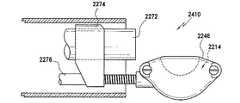
上述した種々の実施形態に加えて、図44、図45および図46を参照すると、縫合器械2410のためのガイドワイヤ導入器2470を用いるのがよいことが考えられる。かかる器具は、上記において詳細に説明した着脱自在な真空チャンバ2446および縫合本体2414と組み合わせて用いられている。遠位端部コンポーネント、即ち、真空チャンバ2446および縫合本体2414は、例えば、内視鏡2472に先立って口腔に通され、次にガイドワイヤ2470を介して内視鏡取り付けリング2474に取り付けられ、このガイドワイヤは、縫合本体2414および真空チャンバ2446を支持シャフト2476上まで引く仕方で支持シャフト2476を通って引かれる。内視鏡2472それ自体を用いて取り外し状態の真空チャンバ2446および縫合本体2414を口腔をくだって前進させるのがよい。内視鏡2472の作業チャネル内のあらかじめ位置決めされたガイドワイヤ2470は、その遠位端部2471が真空チャンバ2446および縫合本体2414に連結することによって終端している。いったん胃の中に通すと、縫合本体2414および真空チャンバ2446が連結されたガイドワイヤ2470の作用により縫合本体2414および真空チャンバ2446を引っ張って内視鏡2472に係合させることにより、真空チャンバ2446および縫合本体2414を内視鏡2472の遠位端部に取り付けるまで、そして支持シャフト2476上まで引き戻す。これにより、挿入中内視鏡への固定取り付け状態になるよう通すことができる側方および厚さ方向に大きな真空チャンバ2446および縫合本体2414を用いることができる。 In addition to the various embodiments described above, with reference to FIGS. 44, 45 and 46, it is contemplated that a
変形実施形態として、真空チャンバを、真空型とほぼ同じまたは同一に見えるが、組織を位置決めするのに真空を利用せず、単にチャンバを縫合されるべき組織に隣接して配置することを利用する非真空型機器と交換可能に使用できる。これにより、食い付きサイズが劇的に減少するだけでなく、組織をポケット内に真空の作用で引き込むことによって生じる場合のある組織への外傷の可能性が減少する。 As an alternative embodiment, the vacuum chamber looks similar or identical to the vacuum mold but utilizes no vacuum to position the tissue and simply places the chamber adjacent to the tissue to be sutured. Can be used interchangeably with non-vacuum equipment. This not only dramatically reduces the bite size, but also reduces the potential for trauma to the tissue that may be caused by drawing the tissue into the pocket by the action of a vacuum.
特に、組織を真空チャンバ内に引き入れるための真空支援無しに用いられることが好ましい手技、もっと正確に言えば、縫合糸を最小限の組織食い付き深さで通すだけの幾つかの手技が存在する。実際には、真空により組織への損傷が誘発される臨床上の状況が存在する。様々なキャビティ深さおよびプロフィールを備えた互換性のある真空チャンバを真空支援無しに縫合器械に用いることができる。 In particular, there are procedures that are preferably used without vacuum assistance to draw the tissue into the vacuum chamber, more precisely, there are several procedures that only allow the suture to pass through with minimal tissue biting depth. . In practice, there are clinical situations in which damage to tissue is induced by vacuum. Compatible vacuum chambers with various cavity depths and profiles can be used in the suturing instrument without vacuum assistance.
取っ手迅速脱着手段もまた、本発明に従って計画され、図47、図48、図49、図50および図51に示されている。この特徴は、上述したようなガイドワイヤ導入器と組み合わせてまたはこれとは別個に利用できる。概要を述べると、この実施形態は、縫合糸ハウジング2524と、弧状経路に沿って運動可能に縫合糸ハウジング2524内に設けられた針2528と、針2528と作動可能に関連していて、組織への縫合糸付けを容易にする仕方の弧状経路に沿う縫合糸が固定された状態の針2528の運動を制御する駆動組立体と、取っ手2570と、細長い可撓性部材、例えば、縫合糸ハウジング2524に取り付けられた遠位端部および取っ手2570に取り付けられた近位端部を有する駆動ケーブル2542と、取っ手2570を可撓性部材2542から解除したり取っ手2570を可撓性部材2542に再取り付けしたりする機構体と、を有する。 A handle quick detachment means is also planned according to the present invention and is shown in FIGS. 47, 48, 49, 50 and 51. This feature can be used in combination with or separately from the guidewire introducer as described above. In overview, this embodiment is associated with a
取っ手迅速脱着手段を利用することにより、縫合本体2514および真空チャンバ2546が連結された可撓性駆動ケーブル2542からの取っ手2570の選択的な脱着による縫合器械2510の遠位側取り外しおよび事前挿通が容易になる。この実施形態によれば、駆動ケーブル2542は、完全組み立てに先立って縫合本体2514および真空チャンバ2546を定位置まで通すことができるようにする際に上述したガイドワイヤと非常によく似た役目を果たすことができる。この改良により、縫合器械2510がその通過中内視鏡の遠位端部側に位置決めされるので所要のプロフィールを減少させる仕方で縫合器械2510を内視鏡の遠位端部から事前に通すことができ、この形態は、プロフィールが縫合器械2510と内視鏡の両方に対応しなければならないので所要の通路を増大させる仕方で縫合器械2510を内視鏡の近位端部から通す形態とは異なっている。 Utilizing the quick handle removal means facilitates distal removal and pre-insertion of the
具体的に説明すると、取っ手2570は、駆動ケーブル2542が作動のために解除可能に固定される取っ手本体2574で構成されている。このことを念頭に置いて、取っ手本体2574は、駆動ケーブル2542が収納された状態で設けられる中央通路2578を有している。取っ手本体2574は、中央握り2580、および以下に詳細に説明する仕方で中央握り2580に対して動くスライダ部材2581で構成されている。中央通路2578は、第1の開口端2582および第2の閉鎖端2584を有している。第2の閉鎖端2584に隣接して、中央握り2580に固定された状態のばね荷重トリガロック2586が設けられている。トリガロック2586は、駆動ケーブル2542の近位先端部2588に沿って設けられた突起2594(例えば、弾頭形先端部)に係合するような寸法形状になっている。このように、駆動ケーブル2542の近位先端部2588は、通路2578の近位端部2592に設けられた凹部2590内、および中央握り2580内に(その心出しのため)設けられ、トリガロック2586は、駆動ケーブル2576を取っ手本体2574内に維持するために下方に動かされて突起2594に係合する。取っ手2570を駆動ケーブル2578から取り外すことが望ましい場合、トリガロック2586をその解除位置に作動させれば済み、取っ手本体2574は、駆動ケーブル2542から自由に取り外せる。取っ手本体2574内への駆動ケーブル2542の保持は、ロックスライダ2596をスライダ部材2581に沿って設けることにより一段と容易になる。ロックスライダ2596は、駆動ケーブル2542に形成されていて、取っ手本体2574を駆動ケーブル上に保持するカラー2598と摩擦により相互作用する。 Specifically, the
実際には、駆動ケーブル2542の遠位端部をスライダ部材2581に形成された通路2578内に挿入する。駆動ケーブル2542を駆動ケーブル2576のカラー2598がスライダ部材2581に沿って形成された開口部2583と位置合わせされるような箇所まで挿入する。この時点で、ロックスライダ2596をスライダ部材2581に沿って滑らせてカラー2598上でこれに沿って動かしてこのカラーに係合させる。この時点で、駆動ケーブル2542をスライダ部材2581に固定する。次に、スライダ部材2581を中央握り2580に対して近位側へ動かして、ついには、駆動ケーブル2542の近位端部2588が中央握り2580に形成された凹部2590内に嵌まるようにする。次に、トリガロック2586をばねで作動させて駆動ケーブル2542の近位先端部2588のところの突起2594に係合させ、それにより駆動ケーブルを中央握り2580および取っ手本体2574に固定する。 In practice, the distal end of
取っ手2570を駆動ケーブル2542にいったん固定すると、その解除は、上述した取り付けステップを逆に実施することにより達成される。具体的に言えば、トリガロック2586を前方に回転させると、突起2594を中央握り2580の凹部2590内から解除することができる。 Once the
上述したように、本発明の取っ手2570は、本発明の縫合器械2510を作動させる仕方で駆動ケーブル2542を作動させることができる。具体的に言えば、駆動ケーブル2542が中央握り2580内に嵌められている状態で中央握り2580とスライダ部材2581を相対運動させると、駆動ケーブルが作動して、駆動組立体が上述したように機能することができる。 As described above, the
選択的に解除可能な連結方式を縫合器械の取っ手に関して上述したが、解除可能な連結方式は、縫合本体をハンドルに連結しているシャフトに、縫合本体を選択的に連結する場合に同様に利用できることが考えられる。このように、縫合本体を体腔内にいったん位置決めすると、縫合本体をシャフトに選択的に連結することができ、縫合本体は、縫合糸を組織に付ける際にいつでも使用可能な状態にある。 Although the selectively releasable connection method has been described above with respect to the suture instrument handle, the releasable connection method is similarly used to selectively connect the suture body to the shaft that connects the suture body to the handle. It is possible to do it. In this way, once the suture body is positioned within the body cavity, the suture body can be selectively coupled to the shaft, and the suture body is ready for use when applying sutures to tissue.
種々の手術室内で利用できる真空圧力は、場所ごとに大きなばらつきがある。必要な真空を最小限に抑える真空チャンバの改良については以下に説明した。しかしながら、かかる構造的な変更は、本発明の内視鏡的縫合器械をどの場所でも使えることを確実にするには十分ではない場合がある。本明細書に詳細に説明する実施形態は、真空チャンバ内の真空を局所的に増強させるための取っ手の改良例である。 The vacuum pressure available in various operating rooms varies greatly from place to place. Improvements to the vacuum chamber that minimize the required vacuum are described below. However, such structural changes may not be sufficient to ensure that the endoscopic suturing instrument of the present invention can be used anywhere. The embodiment described in detail herein is an improved handle for locally enhancing the vacuum in a vacuum chamber.
これら実施形態は各々、内視鏡に用いられるよう構成された内視鏡的器械、例えば縫合器械を提供する。この内視鏡的器械は、遠位端部および近位端部を備えた細長い管と、細長い管の遠位端部に取り付けられたエンドエフェクタ、例えば縫合器械の縫合本体と、細長い管の近位端部に取り付けられた取っ手とを有する。取っ手は、器械を第1の真空源に取り付ける機構体を有する。取っ手は、取っ手と一体であって、第1の真空源を増幅する第2の真空源を更に有し、それにより、第1および第2の真空源は、互いに組み合わさってエンドエフェクタを作動させる。 Each of these embodiments provides an endoscopic instrument, such as a suturing instrument, configured to be used in an endoscope. The endoscopic instrument includes an elongated tube having a distal end and a proximal end, an end effector attached to the distal end of the elongated tube, such as a suture body of a suture instrument, and an elongated tube. And a handle attached to the rear end. The handle has a mechanism for attaching the instrument to the first vacuum source. The handle is further integral with the handle and further includes a second vacuum source that amplifies the first vacuum source, whereby the first and second vacuum sources combine with each other to activate the end effector. .
図64を参照すると、本発明の課題は、シリンジを利用した取っ手真空支援装置2970を設けることにより取り組まれている。本発明の好ましい実施形態によれば、シリンジ機構体2972は、縫合器械2910に取り付けられた主真空アタッチメント2973に平行に配置される。これにより、通常の手術室内真空源を用いてこれが達成できる作用と同じほど多くの作用を達成することができ、良好な組織食い付きを得るのに依然として追加の真空が必要な場合、外科医は、シリンジ機構体2972を引いて真空チャンバ2946内の真空度を高めることができる。手術室の通常利用できる真空源は、組織を真空チャンバ2946内に引き込む主要な機構なので、シリンジ機構体2972内で必要な容積は、完全深さまでではないが、組織が既に真空チャンバ2946内に係合されているので、最小限に抑えられる。手術室真空源を支援するこの方法の追加の利点は、流体が通常のまたは主要な手術室吸引手段によって真空チャンバ2946から既に排出され、シリンジ機構体2972が体液で満たされることはないということにある。 Referring to FIG. 64, the subject of the present invention is addressed by providing a handle vacuum assist
別の実施形態によれば、図65を参照すると、吸引作動のためのバッテリ3071により動力供給されるマルチストローク型真空支援装置3070が提供されている。真空支援装置3070は、手術室の主要真空源を完全に係合させた後、真空チャンバから引き出すことができるガスの最大容積を増大させるようマルチストローク方式で用いられる回転流体ポンプ3072(ローブポンプ、歯車ポンプ、蠕動ポンプ等)を含む。これは、シリンジ形システムと同一の利点を有するが、多量のガスを交換する能力を提供する。 According to another embodiment, referring to FIG. 65, a multi-stroke vacuum assist
同様に、図66を参照すると、バッテリ3171により作動される使い捨て真空ポンプ3170が、本発明の縫合器械3110と関連して用いられる使い捨て配備取っ手3172と関連している。詳細に上述した機械的マルチストローク機構体と同様、バッテリ式モータ駆動式使い捨て流体ポンプ3170が、手術室から利用できる真空を補充するために取っ手3172内に設けられている。 Similarly, referring to FIG. 66, a
図65および図66は、補助真空源を作るよう自動的に作動されるシステムを開示しているが、図67は、トリガ作動式システム3070aを開示している。トリガ3074aは、流体ポンプ、例えば単一ローブ流体ポンプ3072aを駆動するよう歯車装置3078aと関連してトリガ取っ手3076aを用いる。先の実施形態の場合と同様、トリガ3074aおよび流体ポンプ3072aを作動させると、手術室の主要真空源が完全に係合された後、真空チャンバから引き出すことができるガスの最大容積が増大する。これは、シリンジ形システムおよび自動化システムの利点と同一の利点を有するが、外科医に、より高い操作性を与える手動による作動を可能にする。 65 and 66 disclose a system that is automatically activated to create an auxiliary vacuum source, while FIG. 67 discloses a trigger-actuated system 3070a. The trigger 3074a uses a trigger handle 3076a in conjunction with the gearing 3078a to drive a fluid pump, eg, a single lobe fluid pump 3072a. As in the previous embodiment, activating trigger 3074a and fluid pump 3072a increases the maximum volume of gas that can be withdrawn from the vacuum chamber after the operating room's main vacuum source is fully engaged. This has the same advantages as the syringe-type and automation systems, but allows manual actuation that gives the surgeon greater operability.
さらに、一方弁を備えたスクイーズ球状体(squeeze bulb)または一方弁もしくは補助吸引ラインを備えたベロー機構体により真空支援を創出できることが考えられる。加うるに、真空支援を間欠的にもたらすよう遊び羽根(idling vane)3172aを更に設けるのがよい。 Furthermore, it is conceivable that vacuum assistance can be created by a squeeze bulb with a one-way valve or a bellows mechanism with a one-way valve or auxiliary suction line. In addition, an
上述したように、縫合器械3510の視覚化は、その正しい使用にとって極めて重要である場合が多い。このことを念頭に置くと、縫合器械3510を改造してその画像化を向上させるのがよい。具体的に言えば、器械3510は、縫合本体3514に取り付けられた遠位端部を備えていて、開口を通って縫合本体3514を体腔内に挿入するための可撓性部材3516、例えば支持シャフトまたは内視鏡を有する。縫合本体3514は、縫合糸が固定された針3528を弧状経路に沿って動かして組織への縫合糸付けを容易にすることができるよう針3528および駆動組立体が収納された縫合糸ハウジング3524を有する。非可視スペクトル検出部材3570が、手技のパラメータを視覚表示装置3572に伝えるために縫合本体3514と関連している。好ましい実施形態によれば、非可視スペクトル検出部材は、視覚表示装置にワイヤレスで結合されている。 As mentioned above, visualization of the
例えば、縫合本体3514内に超音波変換器3570を設けることにより縫合器械3510を改造するのがよいことが考えられる(図83および図84参照)。同様に、局所縫合糸部位を画像化するために磁気共鳴画像化源変換器を縫合本体または真空チャンバ内に設けることにより縫合器械3510を改造することができる。さらに、縫合糸配備後の縫合糸が付けられた領域への血液の流れを評価しまたは血液の流れの視覚化のために縫合糸配備前に内部の内層中の血液が豊富な領域を識別するための赤外線イメージングセンサを縫合本体または真空チャンバ内に設けることにより内視鏡的縫合器械を改造することができる。内視鏡的縫合器械は、縫合器械内に設けられ、縫合ラインを配備する前または後に血液の流れ特性を評価するレーザードップラセンサ、酸素センサまたは炭酸ガスセンサを更に有するのがよい。 For example, it is conceivable that the
これら種々の視覚化技術は、縫合器械内に組み込まれ、縫合中、部位の視覚化を向上させる、非可視(通常の可視スペクトルの範囲外)画像化を可能にする。上述したように、想定される機構体は、超音波センサ、赤外線センサ、MRIセンサ、レーザードップラセンサ、酸素センサ、および炭酸ガスセンサまたは他のセンサシステムであるのがよい。加うるに、これらセンサは、周りの器官幾何学的形状の存在場所を視認する組織穿通視覚化手段、および縫合糸配備深さおよび食い付きサイズを視認する組織穿通視覚化手段となる。 These various visualization techniques are incorporated into the suturing instrument to allow invisible (outside the normal visible spectrum) imaging that improves the visualization of the site during suturing. As mentioned above, the envisaged mechanism may be an ultrasonic sensor, an infrared sensor, an MRI sensor, a laser Doppler sensor, an oxygen sensor, and a carbon dioxide sensor or other sensor system. In addition, these sensors provide a tissue penetration visualization means for viewing the location of surrounding organ geometry and a tissue penetration visualization means for viewing suture deployment depth and bite size.
図85を参照すると種々のサイズの針3628および縫合糸3612の装填のためのカートリッジ3670が開示されている。好ましい実施形態によれば、再装填可能なカートリッジ3670は、種々のサイズの針3628および種々のサイズの縫合糸3612を装填することができる。カートリッジ3670は、開示した実施形態に従って針3628を取り付けたチャネル3672内にいつでも取り付けることができるような寸法形状になっている。特に、縫合本体3614は、カバー3674を備え、このカバーは、針3628が設けられたチャネル3672への接近およびその閉鎖を可能にする。カートリッジ型システムの具体化により、着脱可能なカートリッジ3670を取り外し、これに代えて新品の針3628および縫合糸3612または異なるサイズの針または縫合糸を用いることができる。 Referring to FIG. 85, a
好ましい実施形態によれば、針3628は、軌道部材3676内に支持され、この軌道部材は、図3〜図10を参照して上述したのと実質的に同様の組立体をつくりだすようチャネル3672内に容易に嵌まる。 According to a preferred embodiment, the
カートリッジ型システムは、簡単なカートリッジ交換により針サイズの調節を可能にするよう更に構成されるのがよい。特に、図86を参照すると、カートリッジ3770の軌道3780は、小さな針3728を設けることにより無駄になった空間を占めるスペーサウェッジ3782を備えている。スペーサウェッジ3782は、縫合器械3710が本発明のこの精神に従って作用できるような仕方で摩擦カム作用部材3738と相互作用するような寸法形状になっている。 The cartridge type system may be further configured to allow needle size adjustment by simple cartridge replacement. In particular, referring to FIG. 86, the
カートリッジ型システムを上記において開示したが、縫合器械の縫合本体は、針だけの簡単な交換を可能にするよう設計されているのがよい。図87および図88を参照すると、これは、開放可能な縫合本体3814を設けることにより達成される。カートリッジ型の再装填を提供するのではなく、再装填のためのこの実施形態は、針3828および縫合糸3812を単に制御するだけで、取り外し可能な部分の無い装置の迅速装填を行う。針3828は、解除できまたは容易に壊すことができるクランプ3872により再装填器3870に結合され、縫合糸3812は、再装填器3870の把握部分3874上で維持される。これにより、針3828に直接触らないで針3828の操作が容易になり、縫合器械3828内への装填に先立って或る形態の縫合糸管理が可能になる。 Although a cartridge-type system has been disclosed above, the suturing body of the suturing instrument should be designed to allow simple replacement of the needle alone. With reference to FIGS. 87 and 88, this is accomplished by providing an
内視鏡下手技を行う際の問題のうちの1つは、縫合をいったん完了すると、結び目を効率的かつ確実に作れるかどうかである。縫合糸の2つの端部または先頭部を同時にぴんと引っ張り次に糸結び要素を用いて隣接の端部を引き締めるのが望ましい。これによって、縫合糸の両端部から均等に締め付ける仕方で、その両端部を引くことができるため、縫合糸の締め付けを弱めることが必要となる前に、作られるステッチの数は最大となるであろう。 One of the problems in performing endoscopic procedures is whether knots can be made efficiently and reliably once the suture is complete. It is desirable to pull the two ends or heads of the suture together at the same time and then tighten the adjacent ends using a knot element. This allows the ends to be pulled evenly from both ends of the suture, so that the number of stitches made is maximized before it becomes necessary to weaken the suture. Let's go.
本発明の好ましい実施形態によれば、通路を通って縫合糸を患者の体内に挿入することにより縫合糸を固定する。次に、縫合糸を組織中へ通してこれから戻す。最後に、縫合糸を定位置に固定する仕方で縫合糸の長さに沿って結び作る。次に、結び目をエネルギーの投与により融合させて、縫合糸の第1の先頭部と第2の先頭部を機械的に結合して結び目を形成する。好ましい実施形態によれば、「融合」という用語は、縫合糸および(または)糸結び要素をこれらの材料成分が固定的に連結される仕方で互いに結合する任意の技術を意味している。 According to a preferred embodiment of the present invention, the suture is secured by inserting the suture through the passageway into the patient's body. The suture is then passed back through the tissue. Finally, the suture is tied along the length of the suture in a manner that secures it in place. Next, the knot is fused by applying energy, and the first and second leading portions of the suture are mechanically joined to form a knot. According to a preferred embodiment, the term “fusion” means any technique that joins sutures and / or yarn knot elements together in such a way that their material components are fixedly connected.
本発明の好ましい実施形態によれば、結び目を作ることは、種々の仕方で達成され、この場合、第1の先頭部と第2の先頭部を互いに対して保持する仕方で第1の先頭部と第2の先頭部を絡ませる。したがって、当業者であれば理解されるように、種々の糸結び技術を本発明に従って用いることができる。例えば、伝統的な結び技術を用いることができ、この場合、縫合糸の第1の先頭部と第2の先頭部を機械的結び目で結び、次にこの結び目を融合させる。 According to a preferred embodiment of the invention, knotting is accomplished in various ways, in which case the first head in a manner that holds the first head and the second head against each other. And entangle the second head. Accordingly, various yarn knotting techniques can be used in accordance with the present invention, as will be appreciated by those skilled in the art. For example, traditional knotting techniques can be used, where the first and second leading ends of the suture are tied with a mechanical knot and then the knot is fused.
好ましい実施形態によれば、図62を参照すると、縫合糸の第1の先頭部2730と第2の先頭部2732を互いに結ぶ縫合糸引っ掛け器具2710が開示されている。引っ掛け器具2710は、2つの部分を用いて縫合糸をキャップ上にロックする。この方法の利点は、キャップ2712が2つの延長アーム2714,2716を有し、かかる延長アームによりキャップをその軸線回りにひねることができ、それにより縫合糸2718の中間長さをそのシャフトに巻き付けることができるということにある。次に、キャップ2712を外側カラー2720内に潰して縫合糸端部2718をロックする。これにより、縫合糸を互いにロックする直前に、細かい張力調整を行うことができる。 According to a preferred embodiment and referring to FIG. 62, a
具体的に説明すると、縫合糸引っ掛け器具2710は、外側カラー2720および外側カラー2720内に嵌まり込むような寸法形状のキャップ2712を有している。外側カラー2720は、全体として円筒形であり、このカラーは、開口上縁部2722および閉鎖ベース2724を有している。キャップ2712は、上方ディスク2726および下方に垂下した中央シャフト2728を有している。上方ディスク2726は、外側カラー2720の開口上縁部2722内に嵌まり込むような寸法形状になっていて、上方ディスクがこのカラー内に摩擦の作用で保持されるようになっている。中央シャフト2728は、小径であり、この中央シャフトは、これに巻き付けられる縫合糸2718のための案内としての役目を果たす。 Specifically, the
キャップ2712は互いに反対側に位置していて、下方に延びる延長アーム2714,2716を更に有している。これらアーム2714,2716は、キャップ2712の回転時に、縫合糸2718をキャップ2712に巻き付けることができる。縫合糸2718をいったんキャップ2712に巻き付けると、ディスク2726を外側カラー2720内に固定し、縫合糸2718を「結び目付き」構造に固定する。 The
種々の機械的糸結び技術を上記において開示したが、本発明の精神から逸脱することなく他の締結方法を利用できることが想定される。例えば、図63を参照すると、結んだ縫合糸の融合は好ましくは、結び目保持性能を向上させるよう縫合糸結び目2810を溶融させるRF、超音波または電気焼灼によって達成される。この方法により、通常の内視鏡的結び目を締め付けた組織領域に隣接して作ることができる。しかしながら、ほどける傾向があるので、次に、エネルギー源(焼灼、超音波、RFまたは他の熱源)を結び目に適用して結び目を互いに融合させる。 Although various mechanical yarn knotting techniques have been disclosed above, it is envisioned that other fastening methods can be utilized without departing from the spirit of the present invention. For example, referring to FIG. 63, fusion of tied sutures is preferably accomplished by RF, ultrasound or electrocautery that melts the
縫合糸のレーシングパターン、締め付け方法および固着手段は全て、器械の使用のしやすさに大きく貢献する。このことを念頭に置いて、種々の縫合技術を開発した。本明細書は、少なくとも好ましいレーシング方法および両端部を同時に締め付ける別の固着方法を詳細に説明するようになっている。 The suture lacing pattern, tightening method and anchoring means all contribute greatly to the ease of use of the instrument. With this in mind, various suturing techniques have been developed. This specification is intended to describe in detail at least the preferred lacing method and another securing method for simultaneously clamping the ends.
以下に説明する種々のレーシング技術に従って、本発明の方法は、針が取り付けられた縫合糸を提供することにより達成される。縫合糸は、第1の先頭部および第2の先頭部を有する。次に、縫合糸付き針を通路を介して器官中に挿入する。単一のステッチを第1の組織部材に入れ、単一のステッチを反対側の間隔を置いた第2の組織部材に入れる。ステッチを入れるステップを少なくとも1回繰り返し、縫合糸を引っ張ることにより第1の組織部材と第2の組織部材を接触させ、それにより、引張り中における縫合糸抗力(ドラグ)を最小限に抑え、更に組織圧縮を実質的に達成する。最後に、縫合糸を第1の組織部材と第2の組織部材が並んで位置する状態で定位置に固定する。 In accordance with the various lacing techniques described below, the method of the present invention is accomplished by providing a suture with an attached needle. The suture has a first leading portion and a second leading portion. Next, a suture needle is inserted into the organ through the passage. A single stitch is placed in the first tissue member and a single stitch is placed in the second spaced apart tissue member. Repeat the stitching step at least once, pulling the suture to bring the first and second tissue members into contact, thereby minimizing suture drag (drag) during pulling, and Substantially achieve tissue compression. Finally, the suture is fixed in place with the first tissue member and the second tissue member positioned side by side.
図52に示す第1の実施形態によれば、付けられた縫合糸4212の締め付けに対する抵抗は、スロー(通し)を逆にするピン技術により達成される。この技術は、伝統的な縫い方を用いて開始される。即ち、縫合糸4212付きの針を挿入し、対向した組織部材4274,4276に沿って交互にステッチを入れる。ステッチは、近位側から遠位側の方向に首尾一貫して入れられ、即ち、組織を通って針を針ステッチが組織に再び入ることにより完了する箇所まで近位側に挿入することにより開始される。「遠位側」および「近位側」という用語が本明細書において用いられているが、当業者であれば理解されるように、これら用語は、相対的であり、最終的には、本発明の精神から逸脱することなく特定の縫い方向を逆にすることができる。 According to the first embodiment shown in FIG. 52, resistance to tightening of the attached
しかしながら、縫合糸4212の最終のスロー4270(即ち、組織に入れられた縫合糸の最終ループまたは最後のステッチ)は、縫合糸4212の最終締め付け中、摩擦を減少させるために変更される。具体的に説明すると、本発明の好ましい実施形態によれば、抗力および摩擦は、最後のステッチ4270を完了した後、反転ピン4272を縫合糸4212と組織壁4274との間に位置決めすることにより減少する。これにより、縫合糸4212をそれ自体オーバーラップさせないでまたはひねり上げないで縫合糸4212を締め付けることができる。かかる構成により、レーシングに打ち勝ち閉鎖状態に締め付けるのに必要な摩擦は、著しく減少することになる。 However, the
別の実施形態によれば、図53を参照すると、付けた縫合糸4312の締め付けに対する抵抗は、スロー反転ピン技術(a throw reverse throw-over technique)により達成される。この技術は、伝統的な縫合技術を用いて開始される。即ち、縫合糸4312付きの針を挿入し、対向した組織部材4374,4376に沿って交互にステッチを入れる。ステッチは、首尾一貫して近位側から遠位側の方向に入れられ、即ち、ステッチは、組織を通って針を針ステッチが組織に再び入ることにより完了する箇所まで近位側に挿入することにより開始される。即ち、縫合糸4312付きの針を挿入し、対向した組織部材に沿って交互にステッチを入れる。ステッチは、首尾一貫して近位側から遠位側の方向に入れられ、即ち、ステッチは、組織を通って針を針ステッチが組織に再び入ることにより完了する箇所まで近位側に挿入することにより開始される。しかしながら、縫合糸4312の最後のスロー4370を逆にして、縫合糸の最終締め付け中、摩擦を減少させ、即ち、最終のスロー4370は、組織を通って針を針のステッチが組織に再び入ることにより完了する箇所まで遠位側の方向に挿入することによって完了する。 According to another embodiment, referring to FIG. 53, resistance to tightening of attached suture 4312 is achieved by a throw reverse throw-over technique. This technique begins with traditional suturing techniques. That is, a needle with a suture 4312 is inserted, and stitches are alternately placed along the opposing
具体的に説明すると、最終のステッチ4370を、これが入れられた方向とは逆にし、このステッチを外科医が縫合糸4312を締め付けるために縫合ラインを引っ張る開始場所に向かって差し向ける。これにより、縫合糸をそれ自体オーバーラップさせないでまたはひねり上げないで縫合糸を締め付けることができる。かかる構成により、レーシングに打ち勝ち閉鎖状態に締め付けるのに必要な摩擦は、著しく減少することになる。 Specifically, the
変形実施形態によれば、図54を参照すると、ステッチの完了時に縫合糸4412を締め付ける能力を向上させるために初期ロックループ4470が用いられている。具体的に説明すると、縫合糸4412の第1の先頭部4412aを、手技全体を通じてユーザが接近できる2つの端部を有する必要なく、縫合ラインの第1の先頭部4412aに沿って組織に固着する。具体的に説明すると、縫合ラインの第1の先頭部または先導端部4412aを縫い、その一部を組織に固着する。しかる後、縫うことは、最終ステッチ4470で完了し、縫合ラインの第2の先頭部または後続端部4412bにその締め付けのために接近する。しかしながら、従来の締め付け方とは対照的に、縫合糸4412を締め付けるのに引っ張る必要があるのは縫合ラインの第2の先頭部4412bだけである。図52および図53に示すように、かかる初期ロックは、本発明の精神の範囲内で他のレーシング技術により採用できる。 According to an alternative embodiment and referring to FIG. 54, an
縫合糸の各組を次の組が縫合器械から配備される前に局所的に締め付けることができるということが考えられる。これにより、上述した最後のステッチステップが、不要にならないまでも最小限に抑えられる。 It is contemplated that each set of sutures can be locally tightened before the next set is deployed from the suture instrument. This minimizes the last stitch step described above, if not necessary.
図55〜図61に示すように、対向した組織部材に通す上述の技術を種々の仕方で拡張できる。例えば、図55を参照すると、縫合糸4512を別々のセグメント4513の状態で付けることができ、この場合、各セグメント4513の第1の端部4512aおよび第2の端部4512bは、それぞれの第1の組織部材4574および第2の組織部材4576に固着される。次に、縫合糸4512の第1の端部4512aを引っ張って縛り、縫合糸を締め付ける。このように(また、他の実施形態に従って以下に説明するように)ステッチのセグメントを用いることにより、ステッチの各セグメントの局所締め付けを組織の引き寄せを向上させるのを助けることができる仕方で実施できる。 As shown in FIGS. 55-61, the techniques described above for passing through opposing tissue members can be extended in various ways. For example, referring to FIG. 55,
図56を参照すると、縫合糸4612を別々のセグメント4613の状態で付けることができ、この場合、縫合糸4612の第1の端部4612aと第2の端部4612bは、糸結び要素4614により結合される。次に、第1の端部4612aおよび第2の端部4612bを引っ張って縫合糸4612を締め付け、糸結び要素4614および縫合糸4612を融合させて縫合糸を定位置に固定する。 Referring to FIG. 56, suture 4612 can be applied in
図57を参照すると、縫合糸4712は、この場合も別々のセグメント4713の状態で付けられている。縫合糸4712の第1の端部4712aは、ループ4716を備え、縫合糸4712の残りの部分は、このループに通されて縫合糸4712の第1の端部4712aを第1の組織部材4774に結合する。縫合糸4712の第2の端部4712bに関し、これを上述したように糸結び要素4714により固定する。具体的に説明すると、第2の端部4712bをループ構造により糸結び要素4714に固定し、このループ構造は、糸結び要素4714に結合された第1のループ4718で構成され、第2の端部4712bの一部は、第2の組織部材4776を通って第2のループ4720を形成し、この第2のループの端部もまた、糸結び要素4714に結合されている。しかる後、第2の端部4712bを引っ張り、特に、第1のループ4718を糸結び要素4714中へ引き込むのがよく、糸結び要素4714および縫合糸4710を融合させて縫合糸4710を定位置に固定する。 Referring to FIG. 57, the
図58を参照すると、縫合糸4812は、別々のセグメント4813の状態で付けられており、縫合糸4812の第1の端部4812aと第2の端部4812bが、糸結び要素4814により結合されている。しかしながら、縫合糸4812の最終スロー4870を図53および図54を参照して上述したように逆にする。次に、第1の端部および第2の端部4812a,4812bを引っ張って縫合糸4812を締め付け、糸結び4814および縫合糸4812を融合させて縫合糸4812を定位置に固定する。 Referring to FIG. 58, the
図59を参照すると、縫合糸4912は、別々のセグメント4913の状態で付けられるのがよく、この場合、各セグメント4913の第1の端部4912aおよび第2の端部4912bは、それぞれの第1の組織部材4974および第2の組織部材4976に固着される。しかしながら、縫合糸4912の各スローを図53および図54を参照して上述したように逆にし、各スローは、縫合糸を遠位側の方向に付けると遠位側の方向から近位側の方向に延びる。次に、縫合糸4912の第1の端部4912aを引っ張って結び、それにより縫合糸4912を締め付ける。図60を参照すると、レーシング技術がセグメントの状態で完成されていないことを除き同一のレーシング技術が利用されている。 Referring to FIG. 59, the
図61に示すように、縫合糸5012の第2の端部5012bを固定するのに止め結び5022を用いるのがよく、他方、縫合糸5012の第1の端部5012aは、組織に固着されている。 As shown in FIG. 61, a
本発明によれば、縫合ラインが組織に係合してこれを保持する能力を向上させるために医用流体/シーラントを施すことが好ましい。特に、縫合ラインは、それを付けた後、短期間にわたり相当大きなひずみを生じ、他方、組織は、相当大きな張力を及ぼしてその元の形態に保持しようとする。これは一般に、手術が終わった後7〜10日間続き、潜在的な縫合糸破断の恐れが高いのは、この期間中である。このことを念頭に置いて、開示する以下の実施形態では、接着剤、シーラントまたは医用流体送り出し機構体を本発明の縫合器械と関連して用いて対向した組織を接着剤で結合することにより胃嚢の短期間強度を増大させるのがよい。シーラントまたは他の医用流体の配備方法は、対向した組織を接着剤で結合することにより組織の剛性を変化させて胃形成術の縫合糸強度を向上させる。 In accordance with the present invention, it is preferred to apply a medical fluid / sealant to improve the ability of the suture line to engage and retain tissue. In particular, the suturing line is subjected to considerable strain over a short period of time after it is applied, while the tissue exerts considerable tension to keep it in its original form. This generally lasts 7-10 days after the surgery is over and it is during this period that there is a high risk of potential suture breakage. With this in mind, in the following disclosed embodiments, an adhesive, sealant or medical fluid delivery mechanism is used in conjunction with the suture instrument of the present invention to bond the opposing tissue with the adhesive. The short-term strength of the sac should be increased. Sealant or other medical fluid deployment methods alter the stiffness of the tissue by bonding the opposing tissue with an adhesive to improve the gastroplasty suture strength.
したがって、図69に示す本発明の好ましい実施形態によれば、縫合ライン3213、即ち縫合糸3212により互いに保持された組織のラインの短期間強度を向上させるために接着剤3210が用いられる。縫合ライン3214を完成させてラインの保持強度を向上させた後、流体シーラントまたは接着剤3210のラインを縫合ライン3214に沿って施すために流体配備機構体が利用される。薄い層の状態の接着剤、フォーミング(空隙充填(void filling))接着剤、またはシーラント3210かのいずれかを縫合糸3212と関連して用いるのがよい。 Thus, according to the preferred embodiment of the present invention shown in FIG. 69, an adhesive 3210 is used to improve the short term strength of the suture lines 3213, ie, the lines of tissue held together by the
変形実施形態によれば、図70、図71および図72を参照すると、縫合糸3312は、その長さに沿って定期的に孔3314が設けられた中空管状縫合糸である。縫合ライン3313をいったん完成させると、縫合糸3312にポンプ作用を及ぼしてシーラントまたは接着剤3314で満たし、それによりシーラントまたは接着剤を縫合糸の長さに沿って全体的に分布させることができ、それにより縫合糸の有効直径を増大させると共に縫合糸の移動を最小限に抑え、しかも、接着剤により縫合ライン3313に加えて組織を互いに補足的に結合することができる。 According to an alternative embodiment, referring to FIGS. 70, 71 and 72, the
図73〜図82を参照すると、更に別の実施形態が開示されている。スリーブ3352を例えば胃3354に形成された内部胃嚢3353周りに形成するために液体ポリマー押出し部3350が用いられている。胃形成術により作られた小さな胃嚢3353および腸の或る長さ分の内部全体は、ポリマー/接着剤3350で被覆される。これにより、胃嚢縫合ラインの強度が向上するだけでなく、手技にとって補足的であり、体重減少具合を向上させる或る形態の吸収不良が潜在的に生じる。 With reference to FIGS. 73-82, yet another embodiment is disclosed. A
具体的に説明すると、種々の図を参照すると、吸引および塗布器具3356を最初に経口的に胃3354の中に挿入する。次に、真空を生じさせて対向した組織表面3358,3360を図73および図74に示すように互いに引き寄せる。しかる後、胃3354の壁3358,3360を並んだ状態に保つ仕方で、真空が引き続き加えられながら、液体ポリマー押出し部3350を対向した組織表面3358,3360に塗布する。最終的に、液体ポリマー押出し部3350は、硬化し、並べられた組織壁3358,3360を並んだ状態に保持する。しかる後、図79および図80を参照すると、本発明の吸引および塗布器具3356を抜去し、胃3354の内部プロフィールを胃の大部分が食べ物吸収から閉鎖された状態で胃を貫通して延びる単純な通路の状態に減少させる。上述した手法は、縫合糸を用いないが、対向した組織を縫合し、次に上述したように接着剤を塗布して胃嚢を確実に形成することができる。 Specifically, with reference to the various figures, the aspiration and
好ましい実施形態を図示するとともに説明したが、かかる開示により本発明を限定するものではなく、これとは異なり、本発明の精神および範囲に属する全ての改造例および変形構成例を包含するものであることは理解されよう。 While the preferred embodiment has been illustrated and described, it is not intended that the invention be limited by such disclosure, but rather encompasses all modifications and variations that fall within the spirit and scope of the invention. It will be understood.
〔実施の態様〕
本発明の具体的な実施態様は、次の通りである。
(1)外科用縫合器械において、
縫合糸ハウジングと、
弧状経路に沿って動くことができるよう前記縫合糸ハウジング内に設けられた針と、
前記針に作動可能に関連している駆動組立体であって、縫合糸を組織に付けやすくする仕方で、前記縫合糸が固定された状態の前記針の前記弧状経路に沿う運動を制御する、駆動組立体と、
前記縫合糸ハウジングを収納する折り畳み式真空チャンバであって、前記真空チャンバは、真空ラインに結合可能な寸法形状になっている、折り畳み式真空チャンバと、
を有する、縫合器械。
(2)実施態様(1)記載の縫合器械において、
前記駆動組立体は、前記針を連続円形経路に沿って動かす、縫合器械。
(3)実施態様(1)記載の縫合器械において、
前記真空チャンバは、前記真空チャンバの内壁に沿って設けられていて、前記真空チャンバ内での組織の保持を促進する突起を有する、縫合器械。
(4)実施態様(1)記載の縫合器械において、
前記真空チャンバは、前記真空チャンバの膨張および収縮を可能にする一体ヒンジを有する、縫合器械。
(5)実施態様(1)記載の縫合器械において、
前記真空チャンバは、弾性である、縫合器械。
(6)実施態様(5)記載の縫合器械において、
前記真空チャンバは、エラストマーである、縫合器械。
(7)実施態様(1)記載の縫合器械において、
前記縫合糸ハウジングは、患者の生まれつき備わった開口中に挿入可能な寸法形状になっている、縫合器械。
(8)実施態様(7)記載の縫合器械において、
前記縫合糸ハウジングは、直径が約3mm〜約24mmの開口を通過可能な寸法形状になっている、縫合器械。
(9)実施態様(1)記載の縫合器械において、
前記縫合糸ハウジングは、トロカール中に腹腔鏡的に挿入可能な寸法形状になっている、縫合器械。
(10)実施態様(9)記載の縫合器械において、
前記縫合糸ハウジングは、直径が約3mm〜約18mmの開口を通過可能な寸法形状になっている、縫合器械。Embodiment
Specific embodiments of the present invention are as follows.
(1) In surgical suturing instruments,
A suture housing;
A needle provided within the suture housing to be movable along an arcuate path;
A drive assembly operatively associated with the needle for controlling movement of the needle along the arcuate path with the suture secured in a manner that facilitates attaching the suture to tissue; A drive assembly;
A collapsible vacuum chamber containing the suture housing, wherein the vacuum chamber is dimensioned to be coupled to a vacuum line;
Having a suturing instrument.
(2) In the suturing device according to the embodiment (1),
The suturing instrument wherein the drive assembly moves the needle along a continuous circular path.
(3) In the suturing device according to the embodiment (1),
The suturing instrument, wherein the vacuum chamber has a protrusion provided along an inner wall of the vacuum chamber and facilitating retention of tissue in the vacuum chamber.
(4) In the suturing device according to the embodiment (1),
The suturing instrument, wherein the vacuum chamber has an integral hinge that allows expansion and contraction of the vacuum chamber.
(5) In the suturing device according to the embodiment (1),
The suturing instrument, wherein the vacuum chamber is elastic.
(6) In the suturing device according to the embodiment (5),
The suturing instrument, wherein the vacuum chamber is an elastomer.
(7) In the suturing device according to the embodiment (1),
The suturing instrument wherein the suture housing is sized and configured for insertion into a patient's natural opening.
(8) In the suturing device according to the embodiment (7),
The suturing instrument wherein the suture housing is dimensioned to pass through an opening having a diameter of about 3 mm to about 24 mm.
(9) In the suturing device according to the embodiment (1),
The suturing instrument wherein the suture housing is dimensioned to be laparoscopically inserted into a trocar.
(10) In the suturing device according to the embodiment (9),
The suturing instrument is sized and configured to pass through an opening having a diameter of about 3 mm to about 18 mm.
(11)患者の生まれつき備わった開口中に挿入可能な外科用縫合器械において、
縫合糸ハウジングと、
弧状経路に沿って動くことができるよう前記縫合糸ハウジング内に設けられた針と、
前記針に作動可能に関連している駆動組立体であって、縫合糸を組織に付けやすくする仕方で、前記縫合糸が固定された状態の前記針の前記弧状経路に沿う運動を制御する、駆動組立体と、
前記縫合糸ハウジングを収納する折り畳み式真空チャンバであって、前記真空チャンバは、真空ラインに結合可能な寸法形状になっている、折り畳み式真空チャンバと、
を有する、外科用縫合器械。
(12)実施態様(11)記載の縫合器械において、
前記駆動組立体は、前記針を連続円形経路に沿って動かす、縫合器械。
(13)実施態様(11)記載の縫合器械において、
前記真空チャンバは、前記真空チャンバの内壁に沿って設けられていて、前記真空チャンバ内での組織の保持を促進する突起を有する、縫合器械。
(14)実施態様(11)記載の縫合器械において、
前記真空チャンバは、弾性である、縫合器械。
(15)実施態様(11)記載の縫合器械において、
前記縫合糸ハウジングは、直径が約3mm〜約24mmの開口を通過可能な寸法形状になっている、縫合器械。(11) In a surgical suturing instrument insertable into a patient's natural opening,
A suture housing;
A needle provided within the suture housing to be movable along an arcuate path;
A drive assembly operatively associated with the needle for controlling movement of the needle along the arcuate path with the suture secured in a manner that facilitates attaching the suture to tissue; A drive assembly;
A collapsible vacuum chamber containing the suture housing, wherein the vacuum chamber is dimensioned to be coupled to a vacuum line;
A surgical suturing instrument.
(12) In the suturing device according to the embodiment (11),
The suturing instrument wherein the drive assembly moves the needle along a continuous circular path.
(13) In the suturing device according to the embodiment (11),
The suturing instrument, wherein the vacuum chamber has a protrusion provided along an inner wall of the vacuum chamber and facilitating retention of tissue in the vacuum chamber.
(14) In the suturing device according to the embodiment (11),
The suturing instrument, wherein the vacuum chamber is elastic.
(15) In the suturing device according to the embodiment (11),
The suturing instrument wherein the suture housing is dimensioned to pass through an opening having a diameter of about 3 mm to about 24 mm.
(16)トロカール中に腹腔鏡的に挿入可能な寸法形状の外科用縫合器械において、
縫合糸ハウジングと、
弧状経路に沿って動くことができるよう前記縫合糸ハウジング内に設けられた針と、
前記針に作動可能に関連している駆動組立体であって、縫合糸を組織に付けやすくする仕方で、前記縫合糸が固定された状態の前記針の前記弧状経路に沿う運動を制御する、駆動組立体と、
前記縫合糸ハウジングを収納する折り畳み式真空チャンバであって、前記真空チャンバは、真空ラインに結合可能な寸法形状になっている、折り畳み式真空チャンバと、
を有する、外科用縫合器械。
(17)実施態様(16)記載の縫合器械において、
前記駆動組立体は、前記針を連続円形経路に沿って動かす、縫合器械。
(18)実施態様(16)記載の縫合器械において、
前記真空チャンバは、前記真空チャンバの内壁に沿って設けられていて、前記真空チャンバ内での組織の保持を促進する突起を有する、縫合器械。
(19)実施態様(16)記載の縫合器械において、
前記真空チャンバは、弾性である、縫合器械。
(20)実施態様(16)記載の縫合器械において、
前記縫合糸ハウジングは、直径が約3mm〜約18mmの開口を通過可能な寸法形状になっている、縫合器械。(16) In a surgical suturing instrument sized and configured to be laparoscopically inserted into a trocar,
A suture housing;
A needle provided within the suture housing to be movable along an arcuate path;
A drive assembly operatively associated with the needle for controlling movement of the needle along the arcuate path with the suture secured in a manner that facilitates attaching the suture to tissue; A drive assembly;
A collapsible vacuum chamber containing the suture housing, wherein the vacuum chamber is dimensioned to be coupled to a vacuum line;
A surgical suturing instrument.
(17) In the suturing device according to the embodiment (16),
The suturing instrument wherein the drive assembly moves the needle along a continuous circular path.
(18) In the suturing device according to the embodiment (16),
The suturing instrument, wherein the vacuum chamber has a protrusion provided along an inner wall of the vacuum chamber and facilitating retention of tissue in the vacuum chamber.
(19) In the suturing device according to the embodiment (16),
The suturing instrument, wherein the vacuum chamber is elastic.
(20) In the suturing device according to the embodiment (16),
The suturing instrument is sized and configured to pass through an opening having a diameter of about 3 mm to about 18 mm.
Claims (12)
Translated fromJapanese縫合糸ハウジングと、
弧状経路に沿って動くことができるよう前記縫合糸ハウジング内に設けられた針と、
前記針に作動可能に関連している駆動組立体であって、縫合糸を組織に付けやすくする仕方で、前記縫合糸が固定された状態の前記針の前記弧状経路に沿う運動を制御する、駆動組立体と、
前記縫合糸ハウジングを収納する折り畳み式真空チャンバであって、前記真空チャンバは、真空ラインに結合可能な寸法形状になっている、折り畳み式真空チャンバと、
を有する、縫合器械。In surgical suturing instruments,
A suture housing;
A needle provided within the suture housing to be movable along an arcuate path;
A drive assembly operatively associated with the needle for controlling movement of the needle along the arcuate path with the suture secured in a manner that facilitates attaching the suture to tissue; A drive assembly;
A collapsible vacuum chamber containing the suture housing, wherein the vacuum chamber is dimensioned to be coupled to a vacuum line;
Having a suturing instrument.
前記駆動組立体は、前記針を連続円形経路に沿って動かす、縫合器械。The suturing instrument according to claim 1,
The suturing instrument wherein the drive assembly moves the needle along a continuous circular path.
前記真空チャンバは、前記真空チャンバの内壁に沿って設けられていて、前記真空チャンバ内での組織の保持を促進する突起を有する、縫合器械。The suturing instrument according to claim 1,
The suturing instrument, wherein the vacuum chamber has a protrusion provided along an inner wall of the vacuum chamber and facilitating retention of tissue in the vacuum chamber.
前記真空チャンバは、前記真空チャンバの膨張および収縮を可能にする一体ヒンジを有する、縫合器械。The suturing instrument according to claim 1,
The suturing instrument, wherein the vacuum chamber has an integral hinge that allows expansion and contraction of the vacuum chamber.
前記真空チャンバは、弾性である、縫合器械。The suturing instrument according to claim 1,
The suturing instrument, wherein the vacuum chamber is elastic.
前記真空チャンバは、エラストマーである、縫合器械。The suturing instrument according to claim 5,
The suturing instrument, wherein the vacuum chamber is an elastomer.
前記縫合糸ハウジングは、患者の生まれつき備わった開口中に挿入可能な寸法形状になっている、縫合器械。The suturing instrument according to claim 1,
The suturing instrument wherein the suture housing is sized and configured for insertion into a patient's natural opening.
前記縫合糸ハウジングは、直径が約3mm〜約24mmの開口を通過可能な寸法形状になっている、縫合器械。The suturing instrument according to claim 7,
The suturing instrument wherein the suture housing is dimensioned to pass through an opening having a diameter of about 3 mm to about 24 mm.
前記縫合糸ハウジングは、トロカール中に腹腔鏡的に挿入可能な寸法形状になっている、縫合器械。The suturing instrument according to claim 1,
The suturing instrument wherein the suture housing is dimensioned to be laparoscopically inserted into a trocar.
前記縫合糸ハウジングは、直径が約3mm〜約18mmの開口を通過可能な寸法形状になっている、縫合器械。The suturing instrument according to claim 9,
The suturing instrument is sized and configured to pass through an opening having a diameter of about 3 mm to about 18 mm.
縫合糸ハウジングと、
弧状経路に沿って動くことができるよう前記縫合糸ハウジング内に設けられた針と、
前記針に作動可能に関連している駆動組立体であって、縫合糸を組織に付けやすくする仕方で、前記縫合糸が固定された状態の前記針の前記弧状経路に沿う運動を制御する、駆動組立体と、
前記縫合糸ハウジングを収納する折り畳み式真空チャンバであって、前記真空チャンバは、真空ラインに結合可能な寸法形状になっている、折り畳み式真空チャンバと、
を有する、外科用縫合器械。In a surgical suturing instrument that can be inserted into a patient's natural opening,
A suture housing;
A needle provided within the suture housing to be movable along an arcuate path;
A drive assembly operatively associated with the needle for controlling movement of the needle along the arcuate path with the suture secured in a manner that facilitates attaching the suture to tissue; A drive assembly;
A collapsible vacuum chamber containing the suture housing, wherein the vacuum chamber is dimensioned to be coupled to a vacuum line;
A surgical suturing instrument.
縫合糸ハウジングと、
弧状経路に沿って動くことができるよう前記縫合糸ハウジング内に設けられた針と、
前記針に作動可能に関連している駆動組立体であって、縫合糸を組織に付けやすくする仕方で、前記縫合糸が固定された状態の前記針の前記弧状経路に沿う運動を制御する、駆動組立体と、
前記縫合糸ハウジングを収納する折り畳み式真空チャンバであって、前記真空チャンバは、真空ラインに結合可能な寸法形状になっている、折り畳み式真空チャンバと、
を有する、外科用縫合器械。In a surgical suturing instrument dimensioned to be laparoscopically inserted into a trocar,
A suture housing;
A needle provided within the suture housing to be movable along an arcuate path;
A drive assembly operatively associated with the needle for controlling movement of the needle along the arcuate path with the suture secured in a manner that facilitates attaching the suture to tissue; A drive assembly;
A collapsible vacuum chamber containing the suture housing, wherein the vacuum chamber is dimensioned to be coupled to a vacuum line;
A surgical suturing instrument.
Applications Claiming Priority (7)
| Application Number | Priority Date | Filing Date | Title |
|---|---|---|---|
| US11/394,178US7976553B2 (en) | 2005-06-13 | 2006-03-31 | Surgical suturing apparatus with detachable handle |
| US11/394,163US7833236B2 (en) | 2005-06-13 | 2006-03-31 | Surgical suturing apparatus with collapsible vacuum chamber |
| US11/394,175US20060282097A1 (en) | 2005-06-13 | 2006-03-31 | Surgical suturing apparatus with a non-visible spectrum sensing member |
| US11/394,163 | 2006-03-31 | ||
| US11/394,169US8500756B2 (en) | 2005-06-13 | 2006-03-31 | Quick load mechanism for a surgical suturing apparatus |
| US11/394,155US7887554B2 (en) | 2005-06-13 | 2006-03-31 | Surgical suturing apparatus with needle position indicator |
| US11/394,125US7828812B2 (en) | 2005-06-13 | 2006-03-31 | Surgical suturing apparatus with needle release system |
Publications (2)
| Publication Number | Publication Date |
|---|---|
| JP2007275574A JP2007275574A (en) | 2007-10-25 |
| JP4949108B2true JP4949108B2 (en) | 2012-06-06 |
Family
ID=41226137
Family Applications (6)
| Application Number | Title | Priority Date | Filing Date |
|---|---|---|---|
| JP2007092231AExpired - Fee RelatedJP4949108B2 (en) | 2006-03-31 | 2007-03-30 | Surgical suturing instrument with foldable vacuum chamber |
| JP2007093328AExpired - Fee RelatedJP5183952B2 (en) | 2006-03-31 | 2007-03-30 | Rapid loading mechanism for a surgical suturing instrument |
| JP2007092990AExpired - Fee RelatedJP5214164B2 (en) | 2006-03-31 | 2007-03-30 | Surgical suture instrument with needle position indicator |
| JP2007093169APendingJP2007275579A (en) | 2006-03-31 | 2007-03-30 | Surgical suturing device equipped with detachable handle |
| JP2007093228AExpired - Fee RelatedJP5183951B2 (en) | 2006-03-31 | 2007-03-30 | Surgical suture instrument with non-visible spectrum detection means |
| JP2007092907ACeasedJP2007275576A (en) | 2006-03-31 | 2007-03-30 | Surgical suturing instrument equipped with needle releasing system |
Family Applications After (5)
| Application Number | Title | Priority Date | Filing Date |
|---|---|---|---|
| JP2007093328AExpired - Fee RelatedJP5183952B2 (en) | 2006-03-31 | 2007-03-30 | Rapid loading mechanism for a surgical suturing instrument |
| JP2007092990AExpired - Fee RelatedJP5214164B2 (en) | 2006-03-31 | 2007-03-30 | Surgical suture instrument with needle position indicator |
| JP2007093169APendingJP2007275579A (en) | 2006-03-31 | 2007-03-30 | Surgical suturing device equipped with detachable handle |
| JP2007093228AExpired - Fee RelatedJP5183951B2 (en) | 2006-03-31 | 2007-03-30 | Surgical suture instrument with non-visible spectrum detection means |
| JP2007092907ACeasedJP2007275576A (en) | 2006-03-31 | 2007-03-30 | Surgical suturing instrument equipped with needle releasing system |
Country Status (10)
| Country | Link |
|---|---|
| US (6) | US20060282097A1 (en) |
| EP (6) | EP1839590A1 (en) |
| JP (6) | JP4949108B2 (en) |
| CN (6) | CN101045002B (en) |
| AT (1) | ATE442812T1 (en) |
| AU (6) | AU2007201313B2 (en) |
| BR (6) | BRPI0706320A2 (en) |
| CA (6) | CA2582964A1 (en) |
| DE (1) | DE602007002429D1 (en) |
| MX (6) | MX2007003981A (en) |
Families Citing this family (329)
| Publication number | Priority date | Publication date | Assignee | Title |
|---|---|---|---|---|
| ES2435094T3 (en) | 2000-05-19 | 2013-12-18 | C.R. Bard, Inc. | Device and method of tissue capture and suturing |
| EP2308391B1 (en) | 2001-06-14 | 2016-08-31 | Endoevolution, Llc | Apparatus for surgical suturing with thread management |
| US6675809B2 (en) | 2001-08-27 | 2004-01-13 | Richard S. Stack | Satiation devices and methods |
| US7097665B2 (en) | 2003-01-16 | 2006-08-29 | Synecor, Llc | Positioning tools and methods for implanting medical devices |
| CN101810521B (en) | 2001-08-27 | 2015-05-13 | 辛尼科有限责任公司 | Satiation devices and methods |
| US7146984B2 (en) | 2002-04-08 | 2006-12-12 | Synecor, Llc | Method and apparatus for modifying the exit orifice of a satiation pouch |
| US7862572B2 (en)* | 2004-09-20 | 2011-01-04 | Endoevolution, Llc | Apparatus and method for minimally invasive suturing |
| WO2004021873A2 (en) | 2002-09-06 | 2004-03-18 | C.R. Bard, Inc. | Integrated endoscope and accessory treatment device |
| US20040143342A1 (en) | 2003-01-16 | 2004-07-22 | Stack Richard S. | Satiation pouches and methods of use |
| CN1822794B (en) | 2003-05-16 | 2010-05-26 | C.R.巴德有限公司 | Single cannula, multiple needle endoscopic suturing system |
| US20050247320A1 (en) | 2003-10-10 | 2005-11-10 | Stack Richard S | Devices and methods for retaining a gastro-esophageal implant |
| US8206456B2 (en) | 2003-10-10 | 2012-06-26 | Barosense, Inc. | Restrictive and/or obstructive implant system for inducing weight loss |
| WO2005105003A1 (en) | 2004-04-26 | 2005-11-10 | Synecor, Llc | Restrictive and/or obstructive implant for inducing weight loss |
| US7993354B1 (en) | 2010-10-01 | 2011-08-09 | Endoevolution, Llc | Devices and methods for minimally invasive suturing |
| US8123764B2 (en) | 2004-09-20 | 2012-02-28 | Endoevolution, Llc | Apparatus and method for minimally invasive suturing |
| US7976555B2 (en) | 2008-07-17 | 2011-07-12 | Endoevolution, Llc | Apparatus and method for minimally invasive suturing |
| US9775600B2 (en) | 2010-10-01 | 2017-10-03 | Endoevolution, Llc | Devices and methods for minimally invasive suturing |
| US20060282097A1 (en) | 2005-06-13 | 2006-12-14 | Ortiz Mark S | Surgical suturing apparatus with a non-visible spectrum sensing member |
| US9055942B2 (en) | 2005-10-03 | 2015-06-16 | Boston Scienctific Scimed, Inc. | Endoscopic plication devices and methods |
| CA2854625C (en) | 2006-01-27 | 2017-01-24 | Suturtek Incorporated | Apparatus and method for tissue closure |
| JP5238702B2 (en) | 2006-09-02 | 2013-07-17 | シネコー・エルエルシー | Intestinal sleeve, installation system thereof, and method thereof |
| US9314361B2 (en) | 2006-09-15 | 2016-04-19 | Boston Scientific Scimed, Inc. | System and method for anchoring stomach implant |
| JP5481194B2 (en) | 2006-10-05 | 2014-04-23 | コヴィディエン リミテッド パートナーシップ | Flexible endoscopic suturing device |
| US8226667B2 (en) | 2006-10-05 | 2012-07-24 | Tyco Healthcare Group Lp | Axial stitching device |
| JP5225996B2 (en) | 2006-10-06 | 2013-07-03 | タイコ ヘルスケア グループ リミテッド パートナーシップ | Endoscopic vessel sealer and divider with flexible articulation shaft |
| US8821518B2 (en)* | 2007-11-05 | 2014-09-02 | Ceterix Orthopaedics, Inc. | Suture passing instrument and method |
| US10441273B2 (en) | 2007-07-03 | 2019-10-15 | Ceterix Orthopaedics, Inc. | Pre-tied surgical knots for use with suture passers |
| US9314234B2 (en) | 2007-07-03 | 2016-04-19 | Ceterix Orthopaedics, Inc. | Pre-tied surgical knots for use with suture passers |
| US8663253B2 (en) | 2007-07-03 | 2014-03-04 | Ceterix Orthopaedics, Inc. | Methods of meniscus repair |
| US9861354B2 (en) | 2011-05-06 | 2018-01-09 | Ceterix Orthopaedics, Inc. | Meniscus repair |
| US8911456B2 (en) | 2007-07-03 | 2014-12-16 | Ceterix Orthopaedics, Inc. | Methods and devices for preventing tissue bridging while suturing |
| US8500809B2 (en) | 2011-01-10 | 2013-08-06 | Ceterix Orthopaedics, Inc. | Implant and method for repair of the anterior cruciate ligament |
| US9211119B2 (en) | 2007-07-03 | 2015-12-15 | Ceterix Orthopaedics, Inc. | Suture passers and methods of passing suture |
| US8465505B2 (en) | 2011-05-06 | 2013-06-18 | Ceterix Orthopaedics, Inc. | Suture passer devices and methods |
| WO2009011881A1 (en) | 2007-07-18 | 2009-01-22 | Barosense, Inc. | Overtube introducer for use in endoscopic bariatric surgery |
| JP5581209B2 (en) | 2007-07-18 | 2014-08-27 | ボストン サイエンティフィック サイムド,インコーポレイテッド | Endoscopic implant system |
| DE202007011510U1 (en)* | 2007-08-16 | 2009-01-02 | Karl Storz Medizinische Nähsysteme GmbH & Co. KG | Endoscopic sewing machine and sewing machine extension for an endoscopic instrument |
| RU2352271C1 (en)* | 2007-10-15 | 2009-04-20 | Федеральное государственное учреждение "Нижегородский научно-исследовательский институт травматологии и ортопедии Федерального агентства по высокотехнологичной медицинской помощи" | Mv vlasov's method of applying of continuous intradermal seam |
| US20090171383A1 (en) | 2007-12-31 | 2009-07-02 | David Cole | Gastric space occupier systems and methods of use |
| US8020741B2 (en) | 2008-03-18 | 2011-09-20 | Barosense, Inc. | Endoscopic stapling devices and methods |
| US8864776B2 (en)* | 2008-04-11 | 2014-10-21 | Covidien Lp | Deployment system for surgical suture |
| US8628545B2 (en) | 2008-06-13 | 2014-01-14 | Covidien Lp | Endoscopic stitching devices |
| US20110040308A1 (en) | 2008-06-13 | 2011-02-17 | Ramiro Cabrera | Endoscopic Stitching Devices |
| US8465502B2 (en) | 2008-08-25 | 2013-06-18 | Covidien Lp | Surgical clip applier and method of assembly |
| US20100057109A1 (en)* | 2008-08-28 | 2010-03-04 | Claude Clerc | Endoscopic suturing device |
| US7934631B2 (en) | 2008-11-10 | 2011-05-03 | Barosense, Inc. | Multi-fire stapling systems and methods for delivering arrays of staples |
| US8398658B2 (en) | 2009-02-21 | 2013-03-19 | Farideh Roshanali | Device and procedure for minimally invasive closure of atrial septal defect without cardiopulmonary bypass |
| US10219796B2 (en) | 2009-02-21 | 2019-03-05 | Farideh Roshanali | Device for percutaneous transcathertral closure of atrial septal defect by deploying pericardial patch |
| EP2429374B1 (en) | 2009-05-01 | 2013-09-25 | Cook Medical Technologies LLC | Medical device for suturing perforations |
| US8961539B2 (en) | 2009-05-04 | 2015-02-24 | Boston Scientific Scimed, Inc. | Endoscopic implant system and method |
| USD708746S1 (en) | 2009-06-10 | 2014-07-08 | Covidien Lp | Handle for surgical device |
| US8696690B2 (en)* | 2009-09-01 | 2014-04-15 | Luis Jose Almodovar | Continuous driver with changeable parameters |
| US8490713B2 (en) | 2009-10-06 | 2013-07-23 | Covidien Lp | Handle assembly for endoscopic suturing device |
| US9011454B2 (en) | 2009-11-09 | 2015-04-21 | Ceterix Orthopaedics, Inc. | Suture passer with radiused upper jaw |
| US11744575B2 (en) | 2009-11-09 | 2023-09-05 | Ceterix Orthopaedics, Inc. | Suture passer devices and methods |
| US9848868B2 (en) | 2011-01-10 | 2017-12-26 | Ceterix Orthopaedics, Inc. | Suture methods for forming locking loops stitches |
| US20120289976A1 (en)* | 2009-11-13 | 2012-11-15 | Rimscience Co., Ltd. | Surgical device and medical needle module having indication function |
| US8403945B2 (en) | 2010-02-25 | 2013-03-26 | Covidien Lp | Articulating endoscopic surgical clip applier |
| EP2571427B1 (en) | 2010-05-21 | 2017-07-19 | Boston Scientific Scimed, Inc. | Tissue-acquisition and fastening devices |
| US8936611B2 (en) | 2010-05-27 | 2015-01-20 | Raptor Surgical, LLC | Apparatus and methods for achilles tendon repair |
| DE102010031943A1 (en)* | 2010-07-22 | 2012-01-26 | Siemens Aktiengesellschaft | Method for marking a predetermined guide path of a medical instrument and orientation device |
| US9913638B2 (en) | 2011-01-10 | 2018-03-13 | Ceterix Orthopaedics, Inc. | Transosteal anchoring methods for tissue repair |
| US8968340B2 (en) | 2011-02-23 | 2015-03-03 | Covidien Lp | Single actuating jaw flexible endolumenal stitching device |
| DE102011107613A1 (en)* | 2011-06-30 | 2013-01-03 | Siegfried Riek | trocar |
| WO2013022959A2 (en)* | 2011-08-08 | 2013-02-14 | Endoevolution, Llc | Devices and methods for minimally invasive suturing |
| US10524778B2 (en) | 2011-09-28 | 2020-01-07 | Ceterix Orthopaedics | Suture passers adapted for use in constrained regions |
| US9492162B2 (en) | 2013-12-16 | 2016-11-15 | Ceterix Orthopaedics, Inc. | Automatically reloading suture passer devices and methods |
| US20130131697A1 (en) | 2011-11-21 | 2013-05-23 | Covidien Lp | Surgical clip applier |
| WO2013087095A1 (en)* | 2011-12-13 | 2013-06-20 | Ethicon Endo-Surgery, Inc. | An applier for anchoring a lining to a hollow organ |
| US9364216B2 (en) | 2011-12-29 | 2016-06-14 | Covidien Lp | Surgical clip applier with integrated clip counter |
| WO2013165942A1 (en) | 2012-05-01 | 2013-11-07 | Brigham And Women's Hospital, Inc. | Suturing device for laparoscopic procedures |
| US11871901B2 (en) | 2012-05-20 | 2024-01-16 | Cilag Gmbh International | Method for situational awareness for surgical network or surgical network connected device capable of adjusting function based on a sensed situation or usage |
| US9532787B2 (en) | 2012-05-31 | 2017-01-03 | Covidien Lp | Endoscopic clip applier |
| CN102813538B (en)* | 2012-09-17 | 2014-12-03 | 北京中法派尔特医疗设备有限公司 | Circular purse-string forceps capable of automatically beating purse-strings |
| US9289205B2 (en) | 2012-12-11 | 2016-03-22 | Raptor Surgical, LLC | Systems for soft tissue repair |
| US9398905B2 (en) | 2012-12-13 | 2016-07-26 | Ethicon Endo-Surgery, Llc | Circular needle applier with offset needle and carrier tracks |
| US9125645B1 (en) | 2013-03-11 | 2015-09-08 | Ethicon Endo-Surgery, Inc. | Reciprocating needle drive without cables |
| US20150351749A1 (en) | 2014-06-06 | 2015-12-10 | Ethicon Endo-Surgery, Inc. | Needle Cartridge with Moveable Cover |
| USD771811S1 (en) | 2013-03-15 | 2016-11-15 | Ethicon Endo-Surgery, Llc | Suture tray |
| US9375212B2 (en) | 2014-06-06 | 2016-06-28 | Ethicon Endo-Surgery, Llc | Circular needle applier with cleats |
| EP2967550A4 (en)* | 2013-03-15 | 2016-11-09 | Anchor Orthopedics Xt Inc | APPARATUS AND METHODS FOR CHARGING SUTURE |
| US9247935B2 (en) | 2013-09-23 | 2016-02-02 | Ceterix Orthopaedics, Inc. | Arthroscopic knot pusher and suture cutter |
| CN104739465B (en)* | 2013-12-31 | 2017-02-15 | 深圳市鹏瑞智能技术应用研究院 | Skin stapler |
| CN204951031U (en) | 2014-04-08 | 2016-01-13 | 赛特里克斯整形公司 | Ware device is worn to draw by suture |
| US9468434B2 (en) | 2014-06-03 | 2016-10-18 | Covidien Lp | Stitching end effector |
| US10004490B2 (en) | 2014-06-06 | 2018-06-26 | Ethicon Llc | Force limited needle driver |
| USD745146S1 (en) | 2014-06-06 | 2015-12-08 | Ethicon Endo-Surgery, Inc. | Surgical suturing device |
| US11103235B2 (en) | 2014-07-08 | 2021-08-31 | Lsi Solutions, Inc. | Rotation adapter and receiver for minimally invasive surgical devices |
| WO2016040054A1 (en) | 2014-09-10 | 2016-03-17 | Boston Scientific Scimed, Inc. | Longitudinal needle passer |
| US11504192B2 (en) | 2014-10-30 | 2022-11-22 | Cilag Gmbh International | Method of hub communication with surgical instrument systems |
| CN107205747B (en) | 2015-01-15 | 2020-09-08 | 柯惠有限合伙公司 | Reusable endoscopic surgical clip applier |
| US10512457B2 (en) | 2015-01-16 | 2019-12-24 | Boston Scientific Scimed, Inc. | Delivery tools for medical implants and methods of using the same |
| US10159491B2 (en) | 2015-03-10 | 2018-12-25 | Covidien Lp | Endoscopic reposable surgical clip applier |
| JP6344674B2 (en)* | 2015-04-20 | 2018-06-20 | メディ チューリップ カンパニー,リミテッド | Surgical linear stapling device |
| US11684358B2 (en) | 2015-04-20 | 2023-06-27 | Boston Scientific Scimed, Inc. | Fusible biodegradable sutures utilizing tissue soldering technology |
| US10022120B2 (en) | 2015-05-26 | 2018-07-17 | Ethicon Llc | Surgical needle with recessed features |
| US10092286B2 (en) | 2015-05-27 | 2018-10-09 | Covidien Lp | Suturing loading unit |
| US10004491B2 (en)* | 2015-06-15 | 2018-06-26 | Ethicon Llc | Suturing instrument with needle motion indicator |
| US9839419B2 (en)* | 2015-06-16 | 2017-12-12 | Ethicon Endo-Surgery, Llc | Suturing instrument with jaw having integral cartridge component |
| US9782164B2 (en)* | 2015-06-16 | 2017-10-10 | Ethicon Endo-Surgery, Llc | Suturing instrument with multi-mode cartridges |
| US9888914B2 (en)* | 2015-06-16 | 2018-02-13 | Ethicon Endo-Surgery, Llc | Suturing instrument with motorized needle drive |
| US9867608B1 (en)* | 2015-06-16 | 2018-01-16 | Ethicon Endo-Surgery, Llc | Suturing instrument with circular needle motion |
| US10327757B1 (en)* | 2015-06-17 | 2019-06-25 | Ethicon Llc | Surgical system with endoscope and suturing instrument |
| US10149678B1 (en)* | 2015-06-17 | 2018-12-11 | Ethicon Llc | Suturing instrument with elastomeric cleat |
| US10226245B2 (en) | 2015-07-21 | 2019-03-12 | Ceterix Orthopaedics, Inc. | Automatically reloading suture passer devices that prevent entanglement |
| CA2995992C (en)* | 2015-08-19 | 2021-12-07 | Lsi Solutions, Inc. | Rotation adapter and receiver for minimally invasive surgical devices |
| AU2016323425B2 (en) | 2015-09-15 | 2020-10-22 | Averto Medical, Inc. | Devices and methods for anchoring a sheath in a tissue cavity |
| US10405853B2 (en) | 2015-10-02 | 2019-09-10 | Ceterix Orthpaedics, Inc. | Knot tying accessory |
| CN108348259B (en) | 2015-11-03 | 2020-12-11 | 柯惠有限合伙公司 | Endoscopic Surgical Fixture Applicator |
| US10905425B2 (en) | 2015-11-10 | 2021-02-02 | Covidien Lp | Endoscopic reposable surgical clip applier |
| US10702280B2 (en) | 2015-11-10 | 2020-07-07 | Covidien Lp | Endoscopic reposable surgical clip applier |
| USD800306S1 (en) | 2015-12-10 | 2017-10-17 | Ethicon Llc | Surgical suturing device |
| CN108472044B (en) | 2016-01-11 | 2021-04-16 | 柯惠有限合伙公司 | endoscope-reserved surgical clip applier |
| AU2016388454A1 (en) | 2016-01-18 | 2018-07-19 | Covidien Lp | Endoscopic surgical clip applier |
| US9439647B1 (en) | 2016-03-02 | 2016-09-13 | Arthrogenx, LLC. | Suture passing instruments and methods |
| US10542970B2 (en) | 2016-05-31 | 2020-01-28 | Covidien Lp | Endoscopic stitching device |
| US11141147B2 (en)* | 2016-08-10 | 2021-10-12 | Apollo Endosurgery Us, Inc. | Endoscopic suturing system having external instrument channel |
| WO2018027788A1 (en) | 2016-08-11 | 2018-02-15 | Covidien Lp | Endoscopic surgical clip applier and clip applying systems |
| CN109640844B (en) | 2016-08-25 | 2021-08-06 | 柯惠Lp公司 | Endoscopic Surgical Clip Appliers and Applicator Systems |
| US10660651B2 (en) | 2016-10-31 | 2020-05-26 | Covidien Lp | Endoscopic reposable surgical clip applier |
| WO2018119459A1 (en) | 2016-12-23 | 2018-06-28 | Brigham And Women's Hospital, Inc. | Systems and methods for suturing tissue |
| USD865964S1 (en) | 2017-01-05 | 2019-11-05 | Ethicon Llc | Handle for electrosurgical instrument |
| US11116514B2 (en) | 2017-02-06 | 2021-09-14 | Covidien Lp | Surgical clip applier with user feedback feature |
| US10492779B2 (en)* | 2017-02-20 | 2019-12-03 | Edwards Lifesciences Corporation | Suturing devices for heart valve surgery |
| US20180242967A1 (en) | 2017-02-26 | 2018-08-30 | Endoevolution, Llc | Apparatus and method for minimally invasive suturing |
| US10898181B2 (en) | 2017-03-17 | 2021-01-26 | Cypris Medical, Inc. | Suturing system |
| US10675043B2 (en) | 2017-05-04 | 2020-06-09 | Covidien Lp | Reposable multi-fire surgical clip applier |
| US10722235B2 (en) | 2017-05-11 | 2020-07-28 | Covidien Lp | Spring-release surgical clip |
| US10660723B2 (en) | 2017-06-30 | 2020-05-26 | Covidien Lp | Endoscopic reposable surgical clip applier |
| US10639032B2 (en) | 2017-06-30 | 2020-05-05 | Covidien Lp | Endoscopic surgical clip applier including counter assembly |
| US10292698B2 (en) | 2017-07-27 | 2019-05-21 | Endoevolution, Llc | Apparatus and method for minimally invasive suturing |
| US10675112B2 (en) | 2017-08-07 | 2020-06-09 | Covidien Lp | Endoscopic surgical clip applier including counter assembly |
| US10932790B2 (en) | 2017-08-08 | 2021-03-02 | Covidien Lp | Geared actuation mechanism and surgical clip applier including the same |
| US10786262B2 (en) | 2017-08-09 | 2020-09-29 | Covidien Lp | Endoscopic reposable surgical clip applier |
| US10786263B2 (en) | 2017-08-15 | 2020-09-29 | Covidien Lp | Endoscopic reposable surgical clip applier |
| US10835341B2 (en) | 2017-09-12 | 2020-11-17 | Covidien Lp | Endoscopic surgical clip applier and handle assemblies for use therewith |
| US10758245B2 (en) | 2017-09-13 | 2020-09-01 | Covidien Lp | Clip counting mechanism for surgical clip applier |
| US10653429B2 (en) | 2017-09-13 | 2020-05-19 | Covidien Lp | Endoscopic surgical clip applier |
| US10835260B2 (en) | 2017-09-13 | 2020-11-17 | Covidien Lp | Endoscopic surgical clip applier and handle assemblies for use therewith |
| US11510741B2 (en) | 2017-10-30 | 2022-11-29 | Cilag Gmbh International | Method for producing a surgical instrument comprising a smart electrical system |
| US11311342B2 (en) | 2017-10-30 | 2022-04-26 | Cilag Gmbh International | Method for communicating with surgical instrument systems |
| US11229436B2 (en) | 2017-10-30 | 2022-01-25 | Cilag Gmbh International | Surgical system comprising a surgical tool and a surgical hub |
| US11129634B2 (en) | 2017-10-30 | 2021-09-28 | Cilag Gmbh International | Surgical instrument with rotary drive selectively actuating multiple end effector functions |
| US11801098B2 (en) | 2017-10-30 | 2023-10-31 | Cilag Gmbh International | Method of hub communication with surgical instrument systems |
| US11911045B2 (en) | 2017-10-30 | 2024-02-27 | Cllag GmbH International | Method for operating a powered articulating multi-clip applier |
| US10932804B2 (en) | 2017-10-30 | 2021-03-02 | Ethicon Llc | Surgical instrument with sensor and/or control systems |
| US11291510B2 (en) | 2017-10-30 | 2022-04-05 | Cilag Gmbh International | Method of hub communication with surgical instrument systems |
| US11925373B2 (en)* | 2017-10-30 | 2024-03-12 | Cilag Gmbh International | Surgical suturing instrument comprising a non-circular needle |
| US11026687B2 (en) | 2017-10-30 | 2021-06-08 | Cilag Gmbh International | Clip applier comprising clip advancing systems |
| US11317919B2 (en) | 2017-10-30 | 2022-05-03 | Cilag Gmbh International | Clip applier comprising a clip crimping system |
| EP3476302B1 (en)* | 2017-10-30 | 2025-03-19 | Ethicon LLC | Surgical suturing instrument comprising a non-circular needle |
| US10736616B2 (en) | 2017-10-30 | 2020-08-11 | Ethicon Llc | Surgical instrument with remote release |
| EP3476301A1 (en)* | 2017-10-30 | 2019-05-01 | Ethicon LLC | Surgical suturing instrument |
| US11564756B2 (en) | 2017-10-30 | 2023-01-31 | Cilag Gmbh International | Method of hub communication with surgical instrument systems |
| WO2019089305A1 (en)* | 2017-10-30 | 2019-05-09 | Ethicon Llc | Surgical suturing instrument configured to manipulate tissue using mechanical and electrical power |
| US11376015B2 (en) | 2017-11-03 | 2022-07-05 | Covidien Lp | Endoscopic surgical clip applier and handle assemblies for use therewith |
| US10932791B2 (en) | 2017-11-03 | 2021-03-02 | Covidien Lp | Reposable multi-fire surgical clip applier |
| US11116513B2 (en) | 2017-11-03 | 2021-09-14 | Covidien Lp | Modular surgical clip cartridge |
| US10945734B2 (en) | 2017-11-03 | 2021-03-16 | Covidien Lp | Rotation knob assemblies and surgical instruments including the same |
| US10828036B2 (en) | 2017-11-03 | 2020-11-10 | Covidien Lp | Endoscopic surgical clip applier and handle assemblies for use therewith |
| US11116509B2 (en) | 2017-11-10 | 2021-09-14 | Avantec Vascular Corporation | System and method for delivering an embolic device |
| US10722236B2 (en) | 2017-12-12 | 2020-07-28 | Covidien Lp | Endoscopic reposable surgical clip applier |
| US10743887B2 (en) | 2017-12-13 | 2020-08-18 | Covidien Lp | Reposable multi-fire surgical clip applier |
| US10849630B2 (en) | 2017-12-13 | 2020-12-01 | Covidien Lp | Reposable multi-fire surgical clip applier |
| US10959737B2 (en) | 2017-12-13 | 2021-03-30 | Covidien Lp | Reposable multi-fire surgical clip applier |
| US11432885B2 (en) | 2017-12-28 | 2022-09-06 | Cilag Gmbh International | Sensing arrangements for robot-assisted surgical platforms |
| US11659023B2 (en) | 2017-12-28 | 2023-05-23 | Cilag Gmbh International | Method of hub communication |
| US12376855B2 (en) | 2017-12-28 | 2025-08-05 | Cilag Gmbh International | Safety systems for smart powered surgical stapling |
| US11304763B2 (en) | 2017-12-28 | 2022-04-19 | Cilag Gmbh International | Image capturing of the areas outside the abdomen to improve placement and control of a surgical device in use |
| US11896322B2 (en) | 2017-12-28 | 2024-02-13 | Cilag Gmbh International | Sensing the patient position and contact utilizing the mono-polar return pad electrode to provide situational awareness to the hub |
| US11666331B2 (en) | 2017-12-28 | 2023-06-06 | Cilag Gmbh International | Systems for detecting proximity of surgical end effector to cancerous tissue |
| US11786245B2 (en) | 2017-12-28 | 2023-10-17 | Cilag Gmbh International | Surgical systems with prioritized data transmission capabilities |
| US11132462B2 (en) | 2017-12-28 | 2021-09-28 | Cilag Gmbh International | Data stripping method to interrogate patient records and create anonymized record |
| US12062442B2 (en) | 2017-12-28 | 2024-08-13 | Cilag Gmbh International | Method for operating surgical instrument systems |
| US10849697B2 (en) | 2017-12-28 | 2020-12-01 | Ethicon Llc | Cloud interface for coupled surgical devices |
| US11832840B2 (en) | 2017-12-28 | 2023-12-05 | Cilag Gmbh International | Surgical instrument having a flexible circuit |
| US12396806B2 (en) | 2017-12-28 | 2025-08-26 | Cilag Gmbh International | Adjustment of a surgical device function based on situational awareness |
| US11419630B2 (en) | 2017-12-28 | 2022-08-23 | Cilag Gmbh International | Surgical system distributed processing |
| US11266468B2 (en) | 2017-12-28 | 2022-03-08 | Cilag Gmbh International | Cooperative utilization of data derived from secondary sources by intelligent surgical hubs |
| US20190201142A1 (en) | 2017-12-28 | 2019-07-04 | Ethicon Llc | Automatic tool adjustments for robot-assisted surgical platforms |
| US12127729B2 (en) | 2017-12-28 | 2024-10-29 | Cilag Gmbh International | Method for smoke evacuation for surgical hub |
| US12096916B2 (en) | 2017-12-28 | 2024-09-24 | Cilag Gmbh International | Method of sensing particulate from smoke evacuated from a patient, adjusting the pump speed based on the sensed information, and communicating the functional parameters of the system to the hub |
| US11069012B2 (en) | 2017-12-28 | 2021-07-20 | Cilag Gmbh International | Interactive surgical systems with condition handling of devices and data capabilities |
| US11424027B2 (en) | 2017-12-28 | 2022-08-23 | Cilag Gmbh International | Method for operating surgical instrument systems |
| US10987178B2 (en) | 2017-12-28 | 2021-04-27 | Ethicon Llc | Surgical hub control arrangements |
| US11937769B2 (en) | 2017-12-28 | 2024-03-26 | Cilag Gmbh International | Method of hub communication, processing, storage and display |
| US10892995B2 (en) | 2017-12-28 | 2021-01-12 | Ethicon Llc | Surgical network determination of prioritization of communication, interaction, or processing based on system or device needs |
| US11540855B2 (en) | 2017-12-28 | 2023-01-03 | Cilag Gmbh International | Controlling activation of an ultrasonic surgical instrument according to the presence of tissue |
| US11832899B2 (en) | 2017-12-28 | 2023-12-05 | Cilag Gmbh International | Surgical systems with autonomously adjustable control programs |
| US11284936B2 (en) | 2017-12-28 | 2022-03-29 | Cilag Gmbh International | Surgical instrument having a flexible electrode |
| US11602393B2 (en) | 2017-12-28 | 2023-03-14 | Cilag Gmbh International | Surgical evacuation sensing and generator control |
| US11376002B2 (en) | 2017-12-28 | 2022-07-05 | Cilag Gmbh International | Surgical instrument cartridge sensor assemblies |
| US11529187B2 (en) | 2017-12-28 | 2022-12-20 | Cilag Gmbh International | Surgical evacuation sensor arrangements |
| US11903601B2 (en) | 2017-12-28 | 2024-02-20 | Cilag Gmbh International | Surgical instrument comprising a plurality of drive systems |
| US11744604B2 (en) | 2017-12-28 | 2023-09-05 | Cilag Gmbh International | Surgical instrument with a hardware-only control circuit |
| US11304745B2 (en) | 2017-12-28 | 2022-04-19 | Cilag Gmbh International | Surgical evacuation sensing and display |
| US11389164B2 (en) | 2017-12-28 | 2022-07-19 | Cilag Gmbh International | Method of using reinforced flexible circuits with multiple sensors to optimize performance of radio frequency devices |
| US11998193B2 (en) | 2017-12-28 | 2024-06-04 | Cilag Gmbh International | Method for usage of the shroud as an aspect of sensing or controlling a powered surgical device, and a control algorithm to adjust its default operation |
| US11818052B2 (en) | 2017-12-28 | 2023-11-14 | Cilag Gmbh International | Surgical network determination of prioritization of communication, interaction, or processing based on system or device needs |
| US20190206569A1 (en) | 2017-12-28 | 2019-07-04 | Ethicon Llc | Method of cloud based data analytics for use with the hub |
| US11464559B2 (en) | 2017-12-28 | 2022-10-11 | Cilag Gmbh International | Estimating state of ultrasonic end effector and control system therefor |
| US11559307B2 (en) | 2017-12-28 | 2023-01-24 | Cilag Gmbh International | Method of robotic hub communication, detection, and control |
| US10695081B2 (en) | 2017-12-28 | 2020-06-30 | Ethicon Llc | Controlling a surgical instrument according to sensed closure parameters |
| US11253315B2 (en) | 2017-12-28 | 2022-02-22 | Cilag Gmbh International | Increasing radio frequency to create pad-less monopolar loop |
| US11051876B2 (en) | 2017-12-28 | 2021-07-06 | Cilag Gmbh International | Surgical evacuation flow paths |
| US11160605B2 (en) | 2017-12-28 | 2021-11-02 | Cilag Gmbh International | Surgical evacuation sensing and motor control |
| US11419667B2 (en) | 2017-12-28 | 2022-08-23 | Cilag Gmbh International | Ultrasonic energy device which varies pressure applied by clamp arm to provide threshold control pressure at a cut progression location |
| US11147607B2 (en) | 2017-12-28 | 2021-10-19 | Cilag Gmbh International | Bipolar combination device that automatically adjusts pressure based on energy modality |
| US11786251B2 (en) | 2017-12-28 | 2023-10-17 | Cilag Gmbh International | Method for adaptive control schemes for surgical network control and interaction |
| US11291495B2 (en) | 2017-12-28 | 2022-04-05 | Cilag Gmbh International | Interruption of energy due to inadvertent capacitive coupling |
| US11559308B2 (en) | 2017-12-28 | 2023-01-24 | Cilag Gmbh International | Method for smart energy device infrastructure |
| US11571234B2 (en) | 2017-12-28 | 2023-02-07 | Cilag Gmbh International | Temperature control of ultrasonic end effector and control system therefor |
| US10932872B2 (en) | 2017-12-28 | 2021-03-02 | Ethicon Llc | Cloud-based medical analytics for linking of local usage trends with the resource acquisition behaviors of larger data set |
| US11026751B2 (en) | 2017-12-28 | 2021-06-08 | Cilag Gmbh International | Display of alignment of staple cartridge to prior linear staple line |
| US11857152B2 (en) | 2017-12-28 | 2024-01-02 | Cilag Gmbh International | Surgical hub spatial awareness to determine devices in operating theater |
| US11576677B2 (en) | 2017-12-28 | 2023-02-14 | Cilag Gmbh International | Method of hub communication, processing, display, and cloud analytics |
| US11096693B2 (en) | 2017-12-28 | 2021-08-24 | Cilag Gmbh International | Adjustment of staple height of at least one row of staples based on the sensed tissue thickness or force in closing |
| US10755813B2 (en) | 2017-12-28 | 2020-08-25 | Ethicon Llc | Communication of smoke evacuation system parameters to hub or cloud in smoke evacuation module for interactive surgical platform |
| US11100631B2 (en) | 2017-12-28 | 2021-08-24 | Cilag Gmbh International | Use of laser light and red-green-blue coloration to determine properties of back scattered light |
| US11896443B2 (en) | 2017-12-28 | 2024-02-13 | Cilag Gmbh International | Control of a surgical system through a surgical barrier |
| US11423007B2 (en) | 2017-12-28 | 2022-08-23 | Cilag Gmbh International | Adjustment of device control programs based on stratified contextual data in addition to the data |
| US11589888B2 (en) | 2017-12-28 | 2023-02-28 | Cilag Gmbh International | Method for controlling smart energy devices |
| US11410259B2 (en) | 2017-12-28 | 2022-08-09 | Cilag Gmbh International | Adaptive control program updates for surgical devices |
| US10966791B2 (en) | 2017-12-28 | 2021-04-06 | Ethicon Llc | Cloud-based medical analytics for medical facility segmented individualization of instrument function |
| US11179208B2 (en) | 2017-12-28 | 2021-11-23 | Cilag Gmbh International | Cloud-based medical analytics for security and authentication trends and reactive measures |
| US11678881B2 (en) | 2017-12-28 | 2023-06-20 | Cilag Gmbh International | Spatial awareness of surgical hubs in operating rooms |
| US11076921B2 (en) | 2017-12-28 | 2021-08-03 | Cilag Gmbh International | Adaptive control program updates for surgical hubs |
| US11056244B2 (en) | 2017-12-28 | 2021-07-06 | Cilag Gmbh International | Automated data scaling, alignment, and organizing based on predefined parameters within surgical networks |
| US11969216B2 (en) | 2017-12-28 | 2024-04-30 | Cilag Gmbh International | Surgical network recommendations from real time analysis of procedure variables against a baseline highlighting differences from the optimal solution |
| US11278281B2 (en) | 2017-12-28 | 2022-03-22 | Cilag Gmbh International | Interactive surgical system |
| US11202570B2 (en) | 2017-12-28 | 2021-12-21 | Cilag Gmbh International | Communication hub and storage device for storing parameters and status of a surgical device to be shared with cloud based analytics systems |
| US11013563B2 (en) | 2017-12-28 | 2021-05-25 | Ethicon Llc | Drive arrangements for robot-assisted surgical platforms |
| US11612444B2 (en) | 2017-12-28 | 2023-03-28 | Cilag Gmbh International | Adjustment of a surgical device function based on situational awareness |
| US11308075B2 (en) | 2017-12-28 | 2022-04-19 | Cilag Gmbh International | Surgical network, instrument, and cloud responses based on validation of received dataset and authentication of its source and integrity |
| US11234756B2 (en) | 2017-12-28 | 2022-02-01 | Cilag Gmbh International | Powered surgical tool with predefined adjustable control algorithm for controlling end effector parameter |
| US10943454B2 (en) | 2017-12-28 | 2021-03-09 | Ethicon Llc | Detection and escalation of security responses of surgical instruments to increasing severity threats |
| US10898622B2 (en) | 2017-12-28 | 2021-01-26 | Ethicon Llc | Surgical evacuation system with a communication circuit for communication between a filter and a smoke evacuation device |
| US11273001B2 (en) | 2017-12-28 | 2022-03-15 | Cilag Gmbh International | Surgical hub and modular device response adjustment based on situational awareness |
| US11364075B2 (en) | 2017-12-28 | 2022-06-21 | Cilag Gmbh International | Radio frequency energy device for delivering combined electrical signals |
| US11446052B2 (en) | 2017-12-28 | 2022-09-20 | Cilag Gmbh International | Variation of radio frequency and ultrasonic power level in cooperation with varying clamp arm pressure to achieve predefined heat flux or power applied to tissue |
| US11257589B2 (en) | 2017-12-28 | 2022-02-22 | Cilag Gmbh International | Real-time analysis of comprehensive cost of all instrumentation used in surgery utilizing data fluidity to track instruments through stocking and in-house processes |
| US11304720B2 (en) | 2017-12-28 | 2022-04-19 | Cilag Gmbh International | Activation of energy devices |
| US11109866B2 (en) | 2017-12-28 | 2021-09-07 | Cilag Gmbh International | Method for circular stapler control algorithm adjustment based on situational awareness |
| US11969142B2 (en) | 2017-12-28 | 2024-04-30 | Cilag Gmbh International | Method of compressing tissue within a stapling device and simultaneously displaying the location of the tissue within the jaws |
| US11304699B2 (en) | 2017-12-28 | 2022-04-19 | Cilag Gmbh International | Method for adaptive control schemes for surgical network control and interaction |
| US11317937B2 (en) | 2018-03-08 | 2022-05-03 | Cilag Gmbh International | Determining the state of an ultrasonic end effector |
| US11464535B2 (en) | 2017-12-28 | 2022-10-11 | Cilag Gmbh International | Detection of end effector emersion in liquid |
| US20190201090A1 (en) | 2017-12-28 | 2019-07-04 | Ethicon Llc | Capacitive coupled return path pad with separable array elements |
| US11324557B2 (en) | 2017-12-28 | 2022-05-10 | Cilag Gmbh International | Surgical instrument with a sensing array |
| US11311306B2 (en) | 2017-12-28 | 2022-04-26 | Cilag Gmbh International | Surgical systems for detecting end effector tissue distribution irregularities |
| US20190201039A1 (en) | 2017-12-28 | 2019-07-04 | Ethicon Llc | Situational awareness of electrosurgical systems |
| WO2019133144A1 (en) | 2017-12-28 | 2019-07-04 | Ethicon Llc | Detection and escalation of security responses of surgical instruments to increasing severity threats |
| US11864728B2 (en) | 2017-12-28 | 2024-01-09 | Cilag Gmbh International | Characterization of tissue irregularities through the use of mono-chromatic light refractivity |
| US20190201112A1 (en) | 2017-12-28 | 2019-07-04 | Ethicon Llc | Computer implemented interactive surgical systems |
| US11633237B2 (en) | 2017-12-28 | 2023-04-25 | Cilag Gmbh International | Usage and technique analysis of surgeon / staff performance against a baseline to optimize device utilization and performance for both current and future procedures |
| US10892899B2 (en) | 2017-12-28 | 2021-01-12 | Ethicon Llc | Self describing data packets generated at an issuing instrument |
| US11179175B2 (en) | 2017-12-28 | 2021-11-23 | Cilag Gmbh International | Controlling an ultrasonic surgical instrument according to tissue location |
| US10944728B2 (en) | 2017-12-28 | 2021-03-09 | Ethicon Llc | Interactive surgical systems with encrypted communication capabilities |
| US10758310B2 (en) | 2017-12-28 | 2020-09-01 | Ethicon Llc | Wireless pairing of a surgical device with another device within a sterile surgical field based on the usage and situational awareness of devices |
| US11696760B2 (en) | 2017-12-28 | 2023-07-11 | Cilag Gmbh International | Safety systems for smart powered surgical stapling |
| US10918310B2 (en) | 2018-01-03 | 2021-02-16 | Biosense Webster (Israel) Ltd. | Fast anatomical mapping (FAM) using volume filling |
| US11166772B2 (en) | 2017-12-28 | 2021-11-09 | Cilag Gmbh International | Surgical hub coordination of control and communication of operating room devices |
| CN108361334A (en)* | 2018-01-16 | 2018-08-03 | 潘隽玮 | One kind connecing the system of connecting based on mechanically operated sequential pass |
| US11051827B2 (en) | 2018-01-16 | 2021-07-06 | Covidien Lp | Endoscopic surgical instrument and handle assemblies for use therewith |
| US12303159B2 (en) | 2018-03-08 | 2025-05-20 | Cilag Gmbh International | Methods for estimating and controlling state of ultrasonic end effector |
| US11534196B2 (en) | 2018-03-08 | 2022-12-27 | Cilag Gmbh International | Using spectroscopy to determine device use state in combo instrument |
| US11259830B2 (en) | 2018-03-08 | 2022-03-01 | Cilag Gmbh International | Methods for controlling temperature in ultrasonic device |
| US11986233B2 (en) | 2018-03-08 | 2024-05-21 | Cilag Gmbh International | Adjustment of complex impedance to compensate for lost power in an articulating ultrasonic device |
| US11213294B2 (en) | 2018-03-28 | 2022-01-04 | Cilag Gmbh International | Surgical instrument comprising co-operating lockout features |
| US11589865B2 (en) | 2018-03-28 | 2023-02-28 | Cilag Gmbh International | Methods for controlling a powered surgical stapler that has separate rotary closure and firing systems |
| US11471156B2 (en) | 2018-03-28 | 2022-10-18 | Cilag Gmbh International | Surgical stapling devices with improved rotary driven closure systems |
| US11096688B2 (en) | 2018-03-28 | 2021-08-24 | Cilag Gmbh International | Rotary driven firing members with different anvil and channel engagement features |
| US11090047B2 (en) | 2018-03-28 | 2021-08-17 | Cilag Gmbh International | Surgical instrument comprising an adaptive control system |
| US11207067B2 (en) | 2018-03-28 | 2021-12-28 | Cilag Gmbh International | Surgical stapling device with separate rotary driven closure and firing systems and firing member that engages both jaws while firing |
| US11278280B2 (en) | 2018-03-28 | 2022-03-22 | Cilag Gmbh International | Surgical instrument comprising a jaw closure lockout |
| US11219453B2 (en) | 2018-03-28 | 2022-01-11 | Cilag Gmbh International | Surgical stapling devices with cartridge compatible closure and firing lockout arrangements |
| US10973520B2 (en) | 2018-03-28 | 2021-04-13 | Ethicon Llc | Surgical staple cartridge with firing member driven camming assembly that has an onboard tissue cutting feature |
| US10660637B2 (en) | 2018-04-06 | 2020-05-26 | Cypris Medical, Inc. | Suturing system |
| US10993721B2 (en) | 2018-04-25 | 2021-05-04 | Covidien Lp | Surgical clip applier |
| US11033261B2 (en) | 2018-05-31 | 2021-06-15 | Cypris Medical, Inc. | Suture system |
| US11298122B2 (en) | 2018-06-07 | 2022-04-12 | EnVision Endoscopy, Inc. | Endoscopic suturing device with circular needle |
| EP3809981A1 (en) | 2018-06-20 | 2021-04-28 | ErgoSuture Corp. | Needle drivers for suturing instruments and methods of manufacture |
| US10786273B2 (en) | 2018-07-13 | 2020-09-29 | Covidien Lp | Rotation knob assemblies for handle assemblies |
| US11571205B2 (en) | 2018-07-16 | 2023-02-07 | Cilag Gmbh International | Surgical visualization feedback system |
| US11197665B2 (en) | 2018-08-06 | 2021-12-14 | Covidien Lp | Needle reload device for use with endostitch device |
| US11219463B2 (en) | 2018-08-13 | 2022-01-11 | Covidien Lp | Bilateral spring for surgical instruments and surgical instruments including the same |
| US11051828B2 (en) | 2018-08-13 | 2021-07-06 | Covidien Lp | Rotation knob assemblies and surgical instruments including same |
| US11246601B2 (en) | 2018-08-13 | 2022-02-15 | Covidien Lp | Elongated assemblies for surgical clip appliers and surgical clip appliers incorporating the same |
| US11344316B2 (en) | 2018-08-13 | 2022-05-31 | Covidien Lp | Elongated assemblies for surgical clip appliers and surgical clip appliers incorporating the same |
| US11278267B2 (en) | 2018-08-13 | 2022-03-22 | Covidien Lp | Latch assemblies and surgical instruments including the same |
| US11147566B2 (en) | 2018-10-01 | 2021-10-19 | Covidien Lp | Endoscopic surgical clip applier |
| USD895112S1 (en) | 2018-11-15 | 2020-09-01 | Ethicon Llc | Laparoscopic bipolar electrosurgical device |
| US11284879B2 (en) | 2018-12-13 | 2022-03-29 | Howmedica Osteonics Corp. | Systems for soft tissue repair |
| SG10201900302SA (en)* | 2019-01-11 | 2020-08-28 | Biobot Surgical Pte Ltd | A needle guide assembly and method of operating the same |
| US11357503B2 (en) | 2019-02-19 | 2022-06-14 | Cilag Gmbh International | Staple cartridge retainers with frangible retention features and methods of using same |
| US11331100B2 (en) | 2019-02-19 | 2022-05-17 | Cilag Gmbh International | Staple cartridge retainer system with authentication keys |
| US11369377B2 (en) | 2019-02-19 | 2022-06-28 | Cilag Gmbh International | Surgical stapling assembly with cartridge based retainer configured to unlock a firing lockout |
| US11317915B2 (en) | 2019-02-19 | 2022-05-03 | Cilag Gmbh International | Universal cartridge based key feature that unlocks multiple lockout arrangements in different surgical staplers |
| US11464511B2 (en) | 2019-02-19 | 2022-10-11 | Cilag Gmbh International | Surgical staple cartridges with movable authentication key arrangements |
| US12257013B2 (en) | 2019-03-15 | 2025-03-25 | Cilag Gmbh International | Robotic surgical systems with mechanisms for scaling camera magnification according to proximity of surgical tool to tissue |
| US11524398B2 (en) | 2019-03-19 | 2022-12-13 | Covidien Lp | Gear drive mechanisms for surgical instruments |
| US20220257236A9 (en)* | 2019-06-06 | 2022-08-18 | EnVision Endoscopy, Inc. | Endoscopic suturing device |
| USD952144S1 (en) | 2019-06-25 | 2022-05-17 | Cilag Gmbh International | Surgical staple cartridge retainer with firing system authentication key |
| USD964564S1 (en) | 2019-06-25 | 2022-09-20 | Cilag Gmbh International | Surgical staple cartridge retainer with a closure system authentication key |
| USD950728S1 (en) | 2019-06-25 | 2022-05-03 | Cilag Gmbh International | Surgical staple cartridge |
| EP3965665A1 (en)* | 2019-07-24 | 2022-03-16 | Boston Scientific Scimed, Inc. | Device for fastening tissue |
| US11382634B2 (en) | 2019-12-18 | 2022-07-12 | Avantec Vascular Corporation | Embolic device suited for ease of delivery and placement |
| US11284963B2 (en) | 2019-12-30 | 2022-03-29 | Cilag Gmbh International | Method of using imaging devices in surgery |
| US12002571B2 (en) | 2019-12-30 | 2024-06-04 | Cilag Gmbh International | Dynamic surgical visualization systems |
| US12207881B2 (en) | 2019-12-30 | 2025-01-28 | Cilag Gmbh International | Surgical systems correlating visualization data and powered surgical instrument data |
| US12053223B2 (en) | 2019-12-30 | 2024-08-06 | Cilag Gmbh International | Adaptive surgical system control according to surgical smoke particulate characteristics |
| US11744667B2 (en) | 2019-12-30 | 2023-09-05 | Cilag Gmbh International | Adaptive visualization by a surgical system |
| US11759283B2 (en) | 2019-12-30 | 2023-09-19 | Cilag Gmbh International | Surgical systems for generating three dimensional constructs of anatomical organs and coupling identified anatomical structures thereto |
| US11896442B2 (en) | 2019-12-30 | 2024-02-13 | Cilag Gmbh International | Surgical systems for proposing and corroborating organ portion removals |
| US11776144B2 (en) | 2019-12-30 | 2023-10-03 | Cilag Gmbh International | System and method for determining, adjusting, and managing resection margin about a subject tissue |
| US11832996B2 (en) | 2019-12-30 | 2023-12-05 | Cilag Gmbh International | Analyzing surgical trends by a surgical system |
| US11779340B2 (en) | 2020-01-02 | 2023-10-10 | Covidien Lp | Ligation clip loading device |
| US11723669B2 (en) | 2020-01-08 | 2023-08-15 | Covidien Lp | Clip applier with clip cartridge interface |
| WO2021171290A1 (en)* | 2020-02-26 | 2021-09-02 | Nitinotes Ltd. | Suturing with an endoluminal gastroplasty device |
| US12114866B2 (en) | 2020-03-26 | 2024-10-15 | Covidien Lp | Interoperative clip loading device |
| CN111481247B (en)* | 2020-04-20 | 2021-04-06 | 广西壮族自治区人民医院 | A stapler for gastroenteroscopy and its operation method |
| US12137899B2 (en) | 2020-05-11 | 2024-11-12 | Cypris Medical, Inc. | Multiple suture placement system |
| JP2023532246A (en)* | 2020-06-22 | 2023-07-27 | エンビジョン・エンドスコピー,インコーポレーテッド | Endoscopic suturing device |
| EP4231947A4 (en) | 2020-10-23 | 2024-10-02 | Envision Endoscopy, Inc. | ENDOSCOPIC SUTURE STRAP |
| US12011161B2 (en)* | 2021-01-21 | 2024-06-18 | Ethicon, Inc. | Suture needle adaptors for delivering suture needles through cannulas while simultaneously visualizing the delivery of the suture needles through the cannulas |
| US12402877B2 (en) | 2021-06-07 | 2025-09-02 | Intuitive Surgical Operations, Inc. | Needle loader devices and related systems and methods |
| FR3138766A1 (en) | 2022-08-11 | 2024-02-16 | Fondation De Cooperation Scientifique - Fcs Ihu De Strasbourg | Surgical suture system including improved cap |
| US12419648B2 (en) | 2022-09-26 | 2025-09-23 | Covidien Lp | Two-part fasteners for surgical clip appliers and surgical clip appliers for deploying the same |
| CN118633979B (en)* | 2024-01-31 | 2025-06-03 | 爱美客技术发展股份有限公司 | Suture device for endoscope skull base dura mater |
Family Cites Families (125)
| Publication number | Priority date | Publication date | Assignee | Title |
|---|---|---|---|---|
| US508063A (en)* | 1893-11-07 | strushqlm | ||
| US1822330A (en)* | 1930-01-13 | 1931-09-08 | Ainslie George | Suturing instrument |
| US3842840A (en)* | 1973-05-07 | 1974-10-22 | E Schweizer | Suture applicator |
| US3946740A (en) | 1974-10-15 | 1976-03-30 | Bassett John W | Suturing device |
| US4345601A (en)* | 1980-04-07 | 1982-08-24 | Mamoru Fukuda | Continuous suturing device |
| SE441643B (en)* | 1983-02-08 | 1985-10-28 | Innova Ab | suturing instrument |
| US4755843A (en)* | 1987-06-12 | 1988-07-05 | Eastman Kodak Company | Temperature control system for a photographic processor |
| US4899746A (en)* | 1988-04-28 | 1990-02-13 | Brunk Industries, Inc. | Suturing apparatus |
| US5454378A (en)* | 1993-02-11 | 1995-10-03 | Symbiosis Corporation | Biopsy forceps having a detachable proximal handle and distal jaws |
| US5080663A (en) | 1990-09-26 | 1992-01-14 | Univerity College London | Sewing device |
| ATE197906T1 (en)* | 1990-10-09 | 2000-12-15 | Medtronic Inc | DEVICE FOR MANIPULATING MATTER |
| US5152769A (en)* | 1991-11-04 | 1992-10-06 | Will Baber | Apparatus for laparoscopic suturing with improved suture needle |
| JPH0721364Y2 (en)* | 1991-12-20 | 1995-05-17 | 武士 倉島 | Tire chain stopper |
| US5478351A (en)* | 1992-06-24 | 1995-12-26 | Microsurge, Inc. | Endoscopic surgical tool with handle and detachable tool assembly |
| US5368606A (en)* | 1992-07-02 | 1994-11-29 | Marlow Surgical Technologies, Inc. | Endoscopic instrument system |
| US5306281A (en)* | 1992-08-31 | 1994-04-26 | Merrimac Industries, Inc. | Suturing cassette device |
| US5364408A (en) | 1992-09-04 | 1994-11-15 | Laurus Medical Corporation | Endoscopic suture system |
| US7060077B2 (en)* | 1992-09-04 | 2006-06-13 | Boston Scientific Scimed, Inc. | Suturing instruments and methods of use |
| US5713910A (en)* | 1992-09-04 | 1998-02-03 | Laurus Medical Corporation | Needle guidance system for endoscopic suture device |
| US5540704A (en)* | 1992-09-04 | 1996-07-30 | Laurus Medical Corporation | Endoscopic suture system |
| US6048351A (en)* | 1992-09-04 | 2000-04-11 | Scimed Life Systems, Inc. | Transvaginal suturing system |
| US5330442A (en) | 1992-10-09 | 1994-07-19 | United States Surgical Corporation | Suture retaining clip |
| GB2272457A (en) | 1992-11-13 | 1994-05-18 | Mark Steven Whiteley | Needle for surgical use |
| US5496347A (en)* | 1993-03-30 | 1996-03-05 | Olympus Optical Co., Ltd. | Surgical instrument |
| US5527321A (en)* | 1993-07-14 | 1996-06-18 | United States Surgical Corporation | Instrument for closing trocar puncture wounds |
| US5507774A (en)* | 1993-07-19 | 1996-04-16 | Wright Medical Technology, Inc. | Surgical instrument capable of disassembly |
| DE4332497C2 (en)* | 1993-09-24 | 1997-04-24 | Stefan Koscher | Surgical instrument |
| US5470338A (en)* | 1993-10-08 | 1995-11-28 | United States Surgical Corporation | Instrument for closing trocar puncture wounds |
| US5474568A (en)* | 1993-10-08 | 1995-12-12 | United States Surgical Corporation | Instrument for closing trocar puncture wounds |
| WO1995011630A1 (en)* | 1993-10-25 | 1995-05-04 | Children's Medical Center Corporation | Retractable suture needle with self-contained driver |
| US5437681A (en)* | 1994-01-13 | 1995-08-01 | Suturtek Inc. | Suturing instrument with thread management |
| GB9405790D0 (en) | 1994-03-23 | 1994-05-11 | Univ London | Sewing device |
| US5462558A (en) | 1994-08-29 | 1995-10-31 | United States Surgical Corporation | Suture clip applier |
| US5514159A (en)* | 1994-09-13 | 1996-05-07 | United States Surgical Corporation | Guillotine suture clip |
| US5718714A (en)* | 1994-10-11 | 1998-02-17 | Circon Corporation | Surgical instrument with removable shaft assembly |
| US5814071A (en) | 1994-11-10 | 1998-09-29 | Innovasive Devices, Inc. | Suture anchor assembly and methods |
| US5645552A (en) | 1995-01-11 | 1997-07-08 | United States Surgical Corporation | Surgical apparatus for suturing body tissue |
| US5540705A (en)* | 1995-05-19 | 1996-07-30 | Suturtek, Inc. | Suturing instrument with thread management |
| FR2734147B1 (en)* | 1995-05-19 | 1997-10-10 | Klein Jean Michel | IMPLANTABLE OSTEOSYNTHESIS DEVICE |
| US5860992A (en)* | 1996-01-31 | 1999-01-19 | Heartport, Inc. | Endoscopic suturing devices and methods |
| US5911727A (en) | 1996-02-20 | 1999-06-15 | Cardiothoracic Systems, Inc. | Stitcher |
| US5709693A (en)* | 1996-02-20 | 1998-01-20 | Cardiothoracic System, Inc. | Stitcher |
| US6436107B1 (en) | 1996-02-20 | 2002-08-20 | Computer Motion, Inc. | Method and apparatus for performing minimally invasive surgical procedures |
| US5782823A (en)* | 1996-04-05 | 1998-07-21 | Eclipse Surgical Technologies, Inc. | Laser device for transmyocardial revascularization procedures including means for enabling a formation of a pilot hole in the epicardium |
| US5810863A (en)* | 1996-06-06 | 1998-09-22 | Moser Medical | Trocar including an obturator with a removable knife |
| US5879306A (en)* | 1996-06-13 | 1999-03-09 | Stryker Corporation | Infrared system for visualizing body members |
| US5855312A (en)* | 1996-07-25 | 1999-01-05 | Toledano; Haviv | Flexible annular stapler for closed surgery of hollow organs |
| US5766186A (en)* | 1996-12-03 | 1998-06-16 | Simon Fraser University | Suturing device |
| US5964717A (en)* | 1997-01-06 | 1999-10-12 | Symbiosis Corporation | Biopsy forceps having detachable handle and distal jaws |
| US5749898A (en)* | 1997-04-08 | 1998-05-12 | Ethicon Endo-Surgery, Inc. | Suture cartridge assembly for a surgical knot |
| US5910105A (en) | 1997-04-14 | 1999-06-08 | C.R. Bard, Inc. | Control handle for an endoscope |
| US6017316A (en) | 1997-06-18 | 2000-01-25 | Biopsys Medical | Vacuum control system and method for automated biopsy device |
| JP4229491B2 (en)* | 1997-07-16 | 2009-02-25 | オリンパス株式会社 | Surgical instrument |
| US5954731A (en)* | 1997-07-29 | 1999-09-21 | Yoon; Inbae | Surgical instrument with multiple rotatably mounted spreadable end effectors |
| IL121752A0 (en) | 1997-09-11 | 1998-02-22 | Gaber Benny | Stitching tool |
| JP4125814B2 (en) | 1998-03-04 | 2008-07-30 | Hoya株式会社 | Ultrasound endoscope |
| WO1999047050A2 (en) | 1998-03-20 | 1999-09-23 | Scimed Life Systems, Inc. | Endoscopic suture systems |
| US6352503B1 (en)* | 1998-07-17 | 2002-03-05 | Olympus Optical Co., Ltd. | Endoscopic surgery apparatus |
| US6036694A (en)* | 1998-08-03 | 2000-03-14 | Innovasive Devices, Inc. | Self-tensioning soft tissue fixation device and method |
| US6460891B1 (en)* | 1998-10-17 | 2002-10-08 | Gregory Glenn Jones | Ski pole |
| US6236336B1 (en)* | 1999-02-24 | 2001-05-22 | Cobra Electronics Corp. | Traffic information warning system with single modulated carrier |
| US6071289A (en)* | 1999-03-15 | 2000-06-06 | Ethicon Endo-Surgery, Inc. | Surgical device for suturing tissue |
| GB9908098D0 (en) | 1999-04-09 | 1999-06-02 | Kabukoba Josaphat J | Methods and apparatus for suturing |
| US6494888B1 (en) | 1999-06-22 | 2002-12-17 | Ndo Surgical, Inc. | Tissue reconfiguration |
| US6835200B2 (en)* | 1999-06-22 | 2004-12-28 | Ndo Surgical. Inc. | Method and devices for tissue reconfiguration |
| US6663639B1 (en)* | 1999-06-22 | 2003-12-16 | Ndo Surgical, Inc. | Methods and devices for tissue reconfiguration |
| US6821285B2 (en)* | 1999-06-22 | 2004-11-23 | Ndo Surgical, Inc. | Tissue reconfiguration |
| US6506196B1 (en)* | 1999-06-22 | 2003-01-14 | Ndo Surgical, Inc. | Device and method for correction of a painful body defect |
| US7744613B2 (en)* | 1999-06-25 | 2010-06-29 | Usgi Medical, Inc. | Apparatus and methods for forming and securing gastrointestinal tissue folds |
| US7416554B2 (en)* | 2002-12-11 | 2008-08-26 | Usgi Medical Inc | Apparatus and methods for forming and securing gastrointestinal tissue folds |
| US6168606B1 (en)* | 1999-11-10 | 2001-01-02 | Palco Labs, Inc. | Single-use lancet device |
| US6527794B1 (en) | 1999-08-10 | 2003-03-04 | Ethicon, Inc. | Self-locking suture anchor |
| US6406424B1 (en)* | 1999-09-16 | 2002-06-18 | Williamson, Iv Warren P. | Tissue stabilizer having an articulating lift element |
| US7037267B1 (en)* | 1999-11-10 | 2006-05-02 | David Lipson | Medical diagnostic methods, systems, and related equipment |
| EP1261282B1 (en)* | 2000-03-03 | 2013-09-25 | C. R. Bard, Inc. | Endoscopic tissue apposition device with multiple suction ports |
| JP2004500206A (en) | 2000-03-03 | 2004-01-08 | シー・アール・バード・インク | Suture clip, supply device and method |
| US6800056B2 (en) | 2000-04-03 | 2004-10-05 | Neoguide Systems, Inc. | Endoscope with guiding apparatus |
| ES2435094T3 (en)* | 2000-05-19 | 2013-12-18 | C.R. Bard, Inc. | Device and method of tissue capture and suturing |
| EP1720347B1 (en)* | 2000-07-03 | 2010-06-23 | Sony Corporation | Optical multilayer structure, optical switching device, and image display |
| US6755843B2 (en)* | 2000-09-29 | 2004-06-29 | Olympus Optical Co., Ltd. | Endoscopic suturing device |
| US6719763B2 (en)* | 2000-09-29 | 2004-04-13 | Olympus Optical Co., Ltd. | Endoscopic suturing device |
| US7033373B2 (en) | 2000-11-03 | 2006-04-25 | Satiety, Inc. | Method and device for use in minimally invasive placement of space-occupying intragastric devices |
| US8313496B2 (en)* | 2001-02-02 | 2012-11-20 | Lsi Solutions, Inc. | System for endoscopic suturing |
| US6997931B2 (en)* | 2001-02-02 | 2006-02-14 | Lsi Solutions, Inc. | System for endoscopic suturing |
| US6558400B2 (en)* | 2001-05-30 | 2003-05-06 | Satiety, Inc. | Obesity treatment tools and methods |
| US7144401B2 (en)* | 2001-06-07 | 2006-12-05 | Olympus Optical Co., Ltd. | Suturing device for endoscope |
| EP2308391B1 (en)* | 2001-06-14 | 2016-08-31 | Endoevolution, Llc | Apparatus for surgical suturing with thread management |
| US6719764B1 (en) | 2001-08-24 | 2004-04-13 | Scimed Life Systems, Inc. | Forward deploying suturing device and methods of use |
| JP3880907B2 (en)* | 2001-08-31 | 2007-02-14 | オリンパス株式会社 | Endoscopic suture device |
| JP2003102668A (en) | 2001-09-28 | 2003-04-08 | Fuji Photo Optical Co Ltd | Tip cap for endoscope |
| CA2461880A1 (en) | 2001-10-04 | 2003-04-10 | Gibbens & Borders, Llc | Apparatus and method for thread advancing |
| JP2005512686A (en)* | 2001-11-09 | 2005-05-12 | カーディオ−オプティクス, インコーポレイテッド | Coronary sinus access catheter with anterior imaging means |
| US7618425B2 (en)* | 2002-01-30 | 2009-11-17 | Olympus Corporation | Endoscopic suturing system |
| US7344545B2 (en)* | 2002-01-30 | 2008-03-18 | Olympus Corporation | Endoscopic suturing system |
| US9155544B2 (en)* | 2002-03-20 | 2015-10-13 | P Tech, Llc | Robotic systems and methods |
| US7862572B2 (en)* | 2004-09-20 | 2011-01-04 | Endoevolution, Llc | Apparatus and method for minimally invasive suturing |
| US7141055B2 (en) | 2002-04-24 | 2006-11-28 | Surgical Connections, Inc. | Resection and anastomosis devices and methods |
| WO2003090630A2 (en) | 2002-04-25 | 2003-11-06 | Tyco Healthcare Group, Lp | Surgical instruments including micro-electromechanical systems (mems) |
| US8105342B2 (en)* | 2002-05-08 | 2012-01-31 | Apollo Endosurgery, Inc. | Apparatus for ligating/suturing living tissues and system for resecting/suturing living tissues |
| US7442198B2 (en)* | 2002-06-12 | 2008-10-28 | Boston Scientific Scimed, Inc. | Suturing instrument with multi-load cartridge |
| US6773440B2 (en)* | 2002-07-02 | 2004-08-10 | Satiety, Inc. | Method and device for use in tissue approximation and fixation |
| JP4373146B2 (en)* | 2002-07-11 | 2009-11-25 | オリンパス株式会社 | Endoscopic suturing device |
| US6746460B2 (en) | 2002-08-07 | 2004-06-08 | Satiety, Inc. | Intra-gastric fastening devices |
| US7214233B2 (en)* | 2002-08-30 | 2007-05-08 | Satiety, Inc. | Methods and devices for maintaining a space occupying device in a relatively fixed location within a stomach |
| AU2003270549A1 (en) | 2002-09-09 | 2004-03-29 | Brian Kelleher | Device and method for endoluminal therapy |
| US7229428B2 (en) | 2002-10-23 | 2007-06-12 | Satiety, Inc. | Method and device for use in endoscopic organ procedures |
| US7220237B2 (en) | 2002-10-23 | 2007-05-22 | Satiety, Inc. | Method and device for use in endoscopic organ procedures |
| US6656194B1 (en) | 2002-11-05 | 2003-12-02 | Satiety, Inc. | Magnetic anchoring devices |
| US7942898B2 (en)* | 2002-12-11 | 2011-05-17 | Usgi Medical, Inc. | Delivery systems and methods for gastric reduction |
| US6908427B2 (en)* | 2002-12-30 | 2005-06-21 | PARÉ Surgical, Inc. | Flexible endoscope capsule |
| US7060079B2 (en) | 2003-01-03 | 2006-06-13 | Eye Plastic Surgery, Ltd. | Surgical instrument for endoscopic suturing of deep subcutaneous tissue |
| WO2004086986A1 (en) | 2003-03-28 | 2004-10-14 | Gibbens Group Llc | Leverage locking reversible cyclic suturing and knot-tying device |
| US7175638B2 (en)* | 2003-04-16 | 2007-02-13 | Satiety, Inc. | Method and devices for modifying the function of a body organ |
| US7862584B2 (en) | 2003-05-07 | 2011-01-04 | Anpa Medical, Inc. | Suture lock |
| US20050070931A1 (en)* | 2003-08-06 | 2005-03-31 | Rhodemann Li | Method and apparatus for creating a restriction in the stomach or other anatomical structure |
| JP2007513717A (en)* | 2003-12-12 | 2007-05-31 | ユーエスジーアイ メディカル インコーポレイテッド | Devices and methods for forming and fixing gastrointestinal tissue folds |
| JP4652713B2 (en) | 2004-04-02 | 2011-03-16 | オリンパス株式会社 | Endoscopic treatment device |
| JP4643328B2 (en) | 2004-04-07 | 2011-03-02 | オリンパス株式会社 | Medical ligature suturing device |
| JP2005296412A (en) | 2004-04-13 | 2005-10-27 | Olympus Corp | Endoscopic treatment apparatus |
| US20060020167A1 (en)* | 2004-06-30 | 2006-01-26 | James Sitzmann | Medical devices for minimally invasive surgeries and other internal procedures |
| JP4618410B2 (en) | 2004-07-06 | 2011-01-26 | 富士フイルム株式会社 | Ultrasound endoscope |
| JP4302602B2 (en) | 2004-09-24 | 2009-07-29 | オリンパス株式会社 | Endoscopic treatment tool, endoscopic treatment system, and support adapter |
| US7736392B2 (en)* | 2005-04-28 | 2010-06-15 | Medtronic, Inc. | Bulking of upper esophageal sphincter for treatment of obesity |
| US20060282097A1 (en) | 2005-06-13 | 2006-12-14 | Ortiz Mark S | Surgical suturing apparatus with a non-visible spectrum sensing member |
| US7615060B2 (en) | 2005-06-13 | 2009-11-10 | Ethicon-Endo Surgery, Inc. | Endoscopic suturing device |
- 2006
- 2006-03-31USUS11/394,175patent/US20060282097A1/ennot_activeAbandoned
- 2006-03-31USUS11/394,163patent/US7833236B2/enactiveActive
- 2006-03-31USUS11/394,125patent/US7828812B2/enactiveActive
- 2006-03-31USUS11/394,155patent/US7887554B2/enactiveActive
- 2006-03-31USUS11/394,169patent/US8500756B2/ennot_activeExpired - Fee Related
- 2006-03-31USUS11/394,178patent/US7976553B2/ennot_activeExpired - Fee Related
- 2007
- 2007-03-27AUAU2007201313Apatent/AU2007201313B2/ennot_activeCeased
- 2007-03-27AUAU2007201316Apatent/AU2007201316B2/ennot_activeCeased
- 2007-03-27AUAU2007201322Apatent/AU2007201322B2/ennot_activeCeased
- 2007-03-27AUAU2007201320Apatent/AU2007201320B2/ennot_activeCeased
- 2007-03-27AUAU2007201318Apatent/AU2007201318B2/ennot_activeCeased
- 2007-03-27AUAU2007201315Apatent/AU2007201315B8/ennot_activeCeased
- 2007-03-28CACA002582964Apatent/CA2582964A1/ennot_activeAbandoned
- 2007-03-29CACA002582921Apatent/CA2582921A1/ennot_activeAbandoned
- 2007-03-29BRBRPI0706320-2Apatent/BRPI0706320A2/ennot_activeIP Right Cessation
- 2007-03-29BRBRPI0704170-5Apatent/BRPI0704170A2/ennot_activeIP Right Cessation
- 2007-03-29CACA002582916Apatent/CA2582916A1/ennot_activeAbandoned
- 2007-03-30BRBRPI0705111-5Apatent/BRPI0705111A/ennot_activeIP Right Cessation
- 2007-03-30EPEP07251430Apatent/EP1839590A1/ennot_activeWithdrawn
- 2007-03-30JPJP2007092231Apatent/JP4949108B2/ennot_activeExpired - Fee Related
- 2007-03-30BRBRPI0705054-2Apatent/BRPI0705054A/ennot_activeIP Right Cessation
- 2007-03-30EPEP07251429Apatent/EP1839589B1/ennot_activeNot-in-force
- 2007-03-30JPJP2007093328Apatent/JP5183952B2/ennot_activeExpired - Fee Related
- 2007-03-30JPJP2007092990Apatent/JP5214164B2/ennot_activeExpired - Fee Related
- 2007-03-30ATAT07251428Tpatent/ATE442812T1/ennot_activeIP Right Cessation
- 2007-03-30EPEP07251428Apatent/EP1839588B1/ennot_activeNot-in-force
- 2007-03-30EPEP07251414Apatent/EP1839587A3/ennot_activeWithdrawn
- 2007-03-30EPEP07251397Apatent/EP1839586B1/ennot_activeNot-in-force
- 2007-03-30JPJP2007093169Apatent/JP2007275579A/enactivePending
- 2007-03-30CACA002583135Apatent/CA2583135A1/ennot_activeAbandoned
- 2007-03-30CACA002583071Apatent/CA2583071A1/ennot_activeAbandoned
- 2007-03-30DEDE602007002429Tpatent/DE602007002429D1/enactiveActive
- 2007-03-30EPEP07251391Apatent/EP1839585B1/ennot_activeNot-in-force
- 2007-03-30JPJP2007093228Apatent/JP5183951B2/ennot_activeExpired - Fee Related
- 2007-03-30CACA002583324Apatent/CA2583324A1/ennot_activeAbandoned
- 2007-03-30JPJP2007092907Apatent/JP2007275576A/ennot_activeCeased
- 2007-04-02CNCN2007100936967Apatent/CN101045002B/ennot_activeExpired - Fee Related
- 2007-04-02CNCNA2007100922216Apatent/CN101044999A/enactivePending
- 2007-04-02CNCN2007100922199Apatent/CN101044997B/ennot_activeExpired - Fee Related
- 2007-04-02BRBRPI0705789-0Apatent/BRPI0705789A/ennot_activeIP Right Cessation
- 2007-04-02CNCN2007100936990Apatent/CN101045004B/ennot_activeExpired - Fee Related
- 2007-04-02BRBRPI0703909-3Apatent/BRPI0703909A/ennot_activeIP Right Cessation
- 2007-04-02MXMX2007003981Apatent/MX2007003981A/enunknown
- 2007-04-02CNCN2007100922273Apatent/CN101045001B/ennot_activeExpired - Fee Related
- 2007-04-02MXMX2007003975Apatent/MX2007003975A/enactiveIP Right Grant
- 2007-04-02MXMX2007003982Apatent/MX2007003982A/enactiveIP Right Grant
- 2007-04-02MXMX2007003971Apatent/MX2007003971A/enactiveIP Right Grant
- 2007-04-02MXMX2007003978Apatent/MX2007003978A/enactiveIP Right Grant
- 2007-04-02CNCN2007100922254Apatent/CN101045000B/ennot_activeExpired - Fee Related
- 2007-04-02MXMX2007003977Apatent/MX2007003977A/enactiveIP Right Grant
Also Published As
Similar Documents
| Publication | Publication Date | Title |
|---|---|---|
| JP4949108B2 (en) | Surgical suturing instrument with foldable vacuum chamber | |
| JP5154127B2 (en) | Surgical suture instrument | |
| JP5183953B2 (en) | Adjustable vacuum chamber for surgical suturing instrument | |
| JP5242071B2 (en) | Attachment device that can be connected to an endoscope | |
| JP5165267B2 (en) | Endoscopic instrument with secondary vacuum source | |
| CA2583327C (en) | Method for instrument insertion through a body orifice | |
| JP2013146613A (en) | Surgical suturing apparatus with detachable handle | |
| AU2007201312B2 (en) | Method for suture lacing | |
| HK1109040A1 (en) | Quick load mechanism for a surgical suturing apparatus | |
| HK1109040B (en) | Quick load mechanism for a surgical suturing apparatus | |
| HK1108340B (en) | Attachment apparatus for coupling with an endoscope | |
| HK1109042A1 (en) | Surgical suturing apparatus with needle position indicator | |
| HK1109042B (en) | Surgical suturing apparatus with needle position indicator | |
| HK1109041B (en) | Surgical suturing apparatus with needle release system | |
| HK1109041A1 (en) | Surgical suturing apparatus with needle release system | |
| HK1108342B (en) | Adjustable vacuum chamber for a surgical suturing apparatus | |
| HK1107923A (en) | Surgical suturing apparatus with detachable handle |
Legal Events
| Date | Code | Title | Description |
|---|---|---|---|
| RD04 | Notification of resignation of power of attorney | Free format text:JAPANESE INTERMEDIATE CODE: A7424 Effective date:20071205 | |
| RD04 | Notification of resignation of power of attorney | Free format text:JAPANESE INTERMEDIATE CODE: A7424 Effective date:20081107 | |
| A621 | Written request for application examination | Free format text:JAPANESE INTERMEDIATE CODE: A621 Effective date:20100330 | |
| A977 | Report on retrieval | Free format text:JAPANESE INTERMEDIATE CODE: A971007 Effective date:20120130 | |
| TRDD | Decision of grant or rejection written | ||
| A01 | Written decision to grant a patent or to grant a registration (utility model) | Free format text:JAPANESE INTERMEDIATE CODE: A01 Effective date:20120207 | |
| A01 | Written decision to grant a patent or to grant a registration (utility model) | Free format text:JAPANESE INTERMEDIATE CODE: A01 | |
| A61 | First payment of annual fees (during grant procedure) | Free format text:JAPANESE INTERMEDIATE CODE: A61 Effective date:20120307 | |
| FPAY | Renewal fee payment (event date is renewal date of database) | Free format text:PAYMENT UNTIL: 20150316 Year of fee payment:3 | |
| R150 | Certificate of patent or registration of utility model | Free format text:JAPANESE INTERMEDIATE CODE: R150 | |
| LAPS | Cancellation because of no payment of annual fees |