JP4946157B2 - Image forming unit - Google Patents
Image forming unitDownload PDFInfo
- Publication number
- JP4946157B2 JP4946157B2JP2006128486AJP2006128486AJP4946157B2JP 4946157 B2JP4946157 B2JP 4946157B2JP 2006128486 AJP2006128486 AJP 2006128486AJP 2006128486 AJP2006128486 AJP 2006128486AJP 4946157 B2JP4946157 B2JP 4946157B2
- Authority
- JP
- Japan
- Prior art keywords
- image forming
- toner
- seal member
- forming unit
- supply
- Prior art date
- Legal status (The legal status is an assumption and is not a legal conclusion. Google has not performed a legal analysis and makes no representation as to the accuracy of the status listed.)
- Expired - Fee Related
Links
- 239000000843powderSubstances0.000claimsdescription21
- 238000007789sealingMethods0.000claimsdescription13
- 238000000034methodMethods0.000description56
- 230000008569processEffects0.000description55
- 238000003756stirringMethods0.000description12
- 238000004140cleaningMethods0.000description10
- 239000000853adhesiveSubstances0.000description8
- 230000001070adhesive effectEffects0.000description8
- 238000013019agitationMethods0.000description8
- 238000012546transferMethods0.000description7
- 238000005192partitionMethods0.000description6
- 230000001105regulatory effectEffects0.000description6
- 238000011161developmentMethods0.000description5
- 230000018109developmental processEffects0.000description5
- 238000010586diagramMethods0.000description5
- 230000002093peripheral effectEffects0.000description5
- 229920000642polymerPolymers0.000description5
- 238000001514detection methodMethods0.000description4
- 230000007246mechanismEffects0.000description4
- 238000006116polymerization reactionMethods0.000description4
- 230000009471actionEffects0.000description3
- 230000015572biosynthetic processEffects0.000description3
- 239000000463materialSubstances0.000description3
- 239000004065semiconductorSubstances0.000description3
- 239000002390adhesive tapeSubstances0.000description2
- 230000007423decreaseEffects0.000description2
- 230000004927fusionEffects0.000description2
- 239000012943hotmeltSubstances0.000description2
- 238000002844meltingMethods0.000description2
- 230000008018meltingEffects0.000description2
- 230000003287optical effectEffects0.000description2
- 238000012545processingMethods0.000description2
- 238000011084recoveryMethods0.000description2
- 229920005989resinPolymers0.000description2
- 239000011347resinSubstances0.000description2
- 238000001179sorption measurementMethods0.000description2
- 230000003068static effectEffects0.000description2
- 238000011144upstream manufacturingMethods0.000description2
- 229920006311Urethane elastomerPolymers0.000description1
- 239000000969carrierSubstances0.000description1
- 230000008859changeEffects0.000description1
- 239000003795chemical substances by applicationSubstances0.000description1
- 238000004891communicationMethods0.000description1
- 238000012790confirmationMethods0.000description1
- 230000000694effectsEffects0.000description1
- 230000008030eliminationEffects0.000description1
- 238000003379elimination reactionMethods0.000description1
- 230000012447hatchingEffects0.000description1
- 238000010438heat treatmentMethods0.000description1
- 238000009434installationMethods0.000description1
- 239000006249magnetic particleSubstances0.000description1
- 238000007790scrapingMethods0.000description1
- 239000000758substrateSubstances0.000description1
- 229920003002synthetic resinPolymers0.000description1
- 239000000057synthetic resinSubstances0.000description1
- 238000003466weldingMethods0.000description1
Images


Classifications
- G—PHYSICS
- G03—PHOTOGRAPHY; CINEMATOGRAPHY; ANALOGOUS TECHNIQUES USING WAVES OTHER THAN OPTICAL WAVES; ELECTROGRAPHY; HOLOGRAPHY
- G03G—ELECTROGRAPHY; ELECTROPHOTOGRAPHY; MAGNETOGRAPHY
- G03G21/00—Arrangements not provided for by groups G03G13/00 - G03G19/00, e.g. cleaning, elimination of residual charge
- G03G21/16—Mechanical means for facilitating the maintenance of the apparatus, e.g. modular arrangements
- G03G21/18—Mechanical means for facilitating the maintenance of the apparatus, e.g. modular arrangements using a processing cartridge, whereby the process cartridge comprises at least two image processing means in a single unit
- G03G21/1803—Arrangements or disposition of the complete process cartridge or parts thereof
- G03G21/1828—Prevention of damage or soiling, e.g. mechanical abrasion
- G03G21/1832—Shielding members, shutter, e.g. light, heat shielding, prevention of toner scattering
- G—PHYSICS
- G03—PHOTOGRAPHY; CINEMATOGRAPHY; ANALOGOUS TECHNIQUES USING WAVES OTHER THAN OPTICAL WAVES; ELECTROGRAPHY; HOLOGRAPHY
- G03G—ELECTROGRAPHY; ELECTROPHOTOGRAPHY; MAGNETOGRAPHY
- G03G15/00—Apparatus for electrographic processes using a charge pattern
- G03G15/01—Apparatus for electrographic processes using a charge pattern for producing multicoloured copies
- G03G15/0105—Details of unit
- G03G15/0121—Details of unit for developing
- G—PHYSICS
- G03—PHOTOGRAPHY; CINEMATOGRAPHY; ANALOGOUS TECHNIQUES USING WAVES OTHER THAN OPTICAL WAVES; ELECTROGRAPHY; HOLOGRAPHY
- G03G—ELECTROGRAPHY; ELECTROPHOTOGRAPHY; MAGNETOGRAPHY
- G03G15/00—Apparatus for electrographic processes using a charge pattern
- G03G15/06—Apparatus for electrographic processes using a charge pattern for developing
- G03G15/08—Apparatus for electrographic processes using a charge pattern for developing using a solid developer, e.g. powder developer
- G03G15/0822—Arrangements for preparing, mixing, supplying or dispensing developer
- G03G15/0877—Arrangements for metering and dispensing developer from a developer cartridge into the development unit
- G03G15/0881—Sealing of developer cartridges
- G03G15/0882—Sealing of developer cartridges by a peelable sealing film
- G—PHYSICS
- G03—PHOTOGRAPHY; CINEMATOGRAPHY; ANALOGOUS TECHNIQUES USING WAVES OTHER THAN OPTICAL WAVES; ELECTROGRAPHY; HOLOGRAPHY
- G03G—ELECTROGRAPHY; ELECTROPHOTOGRAPHY; MAGNETOGRAPHY
- G03G2215/00—Apparatus for electrophotographic processes
- G03G2215/01—Apparatus for electrophotographic processes for producing multicoloured copies
- G03G2215/0103—Plural electrographic recording members
- G03G2215/0119—Linear arrangement adjacent plural transfer points
- G—PHYSICS
- G03—PHOTOGRAPHY; CINEMATOGRAPHY; ANALOGOUS TECHNIQUES USING WAVES OTHER THAN OPTICAL WAVES; ELECTROGRAPHY; HOLOGRAPHY
- G03G—ELECTROGRAPHY; ELECTROPHOTOGRAPHY; MAGNETOGRAPHY
- G03G2221/00—Processes not provided for by group G03G2215/00, e.g. cleaning or residual charge elimination
- G03G2221/16—Mechanical means for facilitating the maintenance of the apparatus, e.g. modular arrangements and complete machine concepts
- G03G2221/18—Cartridge systems
- G03G2221/183—Process cartridge
Landscapes
- Physics & Mathematics (AREA)
- General Physics & Mathematics (AREA)
- Engineering & Computer Science (AREA)
- Computer Vision & Pattern Recognition (AREA)
- Dry Development In Electrophotography (AREA)
Description
Translated fromJapanese本発明は、複写機、プリンタ、ファクシミリ、これらの複合機等の電子写真方式を用いて記録用紙等の記録媒体に画像を形成する画像形成装置等に用いられる収容物供給容器等に関する。 The present invention relates to a container supply container used in an image forming apparatus that forms an image on a recording medium such as a recording sheet using an electrophotographic system such as a copying machine, a printer, a facsimile machine, or a multifunction machine of these.
電子写真方式を利用する複写機やプリンタ等の画像形成装置は、たとえば感光体ドラム上に形成された静電潜像を、現像装置によって現像剤(トナー)で現像して顕像化(トナー像化)し、このトナー像を記録用紙等の記録媒体上に転写・定着するように構成されている。 An image forming apparatus such as a copying machine or a printer using an electrophotographic system develops, for example, an electrostatic latent image formed on a photosensitive drum with a developer (toner) by a developing device to make a visible image (toner image). The toner image is transferred and fixed on a recording medium such as a recording sheet.
このような画像形成装置に用いられる現像装置における現像方式には、磁性トナーを使用する一成分現像方式と、トナーと磁性キャリアとを混合した二成分現像剤を使用する二成分現像方式とがある。近時、特にカラー画像形成装置においては、磁性体粒子を含まないカラートナーを使用する二成分現像方式が主流となっている。
一成分または二成分のいずれの現像方式の現像装置であっても、画像形成に伴って消費されるトナーを補充する構成が必要となる。The developing system used in such an image forming apparatus includes a one-component developing system using a magnetic toner and a two-component developing system using a two-component developer in which toner and a magnetic carrier are mixed. . In recent years, particularly in color image forming apparatuses, a two-component development method using color toners that do not contain magnetic particles has become mainstream.
Regardless of the one-component or two-component developing system, a configuration for replenishing toner consumed in association with image formation is required.
トナーの補充は、通常、現像装置に着脱可能な現像剤収容容器(トナーカートリッジ)を用いて行われるように構成される。
トナーカートリッジは、トナーを現像装置に供給するための開口部を備えており、その開口部はシール部材によって塞がれ、内部にトナーを収容する。
開口部を塞ぐシール部材は、トナーカートリッジを現像装置に装着した後、外部からの操作によって開口部を開放することができるように構成され、これによってトナーの飛散を防いでトナーを現像装置に供給することができるようになっている。The toner replenishment is usually configured to be performed using a developer container (toner cartridge) that is detachable from the developing device.
The toner cartridge includes an opening for supplying toner to the developing device, and the opening is closed by a seal member and accommodates the toner therein.
The seal member that closes the opening is configured so that the opening can be opened by an external operation after the toner cartridge is mounted on the developing device, thereby preventing toner scattering and supplying the toner to the developing device. Can be done.
そのようなシール部材として、たとえば、シールテープを用いるものが知られている。シールテープを用いる構成では、シールテープは、開口部を覆って接着されると共に、開口部の長手方向一方の端で折り返されて他方の端部側に戻され、その先端を外部に突出させて設けられる。これにより、外部に突出する端部を引っ張ることで、シールテープが奥側から剥離し、開口部を開放させることができる。
なお、シールテープとしては、基材である樹脂テープの一面に、熱によって溶融する融着層が形成され、熱板等によって加熱加圧することで融着層が溶融して対象部位(開口部)に接着するいわゆるヒートシールが多く用いられる。As such a seal member, for example, one using a seal tape is known. In the configuration using the seal tape, the seal tape is adhered to cover the opening, folded back at one end in the longitudinal direction of the opening and returned to the other end, and the tip protrudes outside. Provided. Thereby, by pulling the end part which protrudes outside, the seal tape is peeled from the back side, and the opening part can be opened.
In addition, as the sealing tape, a fusion layer that is melted by heat is formed on one surface of a resin tape that is a base material, and the fusion layer is melted by heating and pressurizing with a hot plate or the like, so that a target portion (opening) A so-called heat seal that adheres to the substrate is often used.
また、トナーの補充の他の形態として、トナー収容容器を備える現像装置と感光体ドラムとが一体に構成された画像形成ユニット(いわゆるプロセスカートリッジ)ごと交換するように構成された画像形成装置も知られている。画像形成ユニットは、画像形成装置本体に着脱可能に構成される。なお、画像形成ユニットには、通常、感光体ドラムの周囲に配設される電子写真プロセスに係る他の機構部品も一体化される。 As another form of toner replenishment, there is also known an image forming apparatus configured to replace an image forming unit (so-called process cartridge) in which a developing device including a toner container and a photosensitive drum are integrally formed. It has been. The image forming unit is configured to be detachable from the image forming apparatus main body. The image forming unit is also usually integrated with other mechanical components related to the electrophotographic process disposed around the photosensitive drum.
このような画像形成ユニットにおいても、トナーを収容するトナー収容室と現像装置との間はシール部材によって塞がれ、輸送中等にトナーが現像装置を介して外部に漏れ出すことを防ぐようになっている。シール部材としては、画像形成ユニットの外部から開放操作を行うことができるように、前述のシールテープを用いる構成が多く採用されている。
そして、画像形成ユニットを交換する際には、新たな画像形成ユニットのシール部材を外して画像形成装置本体に装着する。シール部材は画像形成ユニットの内部の収容室と現像装置との間を隔絶するものであるため、シール部材を外して装着作業を行っても直ちにトナーが飛散することはない。Also in such an image forming unit, a gap between the toner storage chamber for storing the toner and the developing device is blocked by the seal member, so that the toner is prevented from leaking outside through the developing device during transportation or the like. ing. As the seal member, a configuration using the above-described seal tape is often employed so that the opening operation can be performed from the outside of the image forming unit.
When replacing the image forming unit, the seal member of the new image forming unit is removed and attached to the image forming apparatus main body. Since the seal member isolates the storage chamber inside the image forming unit and the developing device, even if the seal member is removed and the mounting operation is performed, the toner does not scatter immediately.
ここで、前述したトナーカートリッジまたは画像形成ユニットのいずれによってトナーの補充を行う構成であっても、シール部材を外さずに誤って画像形成装置を駆動すると、トナーが供給されないばかりかシール部材を可動部に巻き込む等の不具合を招来する虞がある。
このため、シール部材が完全に除去されていることを確認する構成が提案されている(特許文献1参照)。
すなわち、特許文献1に開示の構成は、シール部材が開封されることにより、画像形成装置の接点部と電気的に接続された導電部が切断され、これによってシール部材の開封を検知するものである。Here, even if the toner is replenished with either the toner cartridge or the image forming unit described above, if the image forming apparatus is erroneously driven without removing the seal member, not only the toner is supplied but also the seal member is movable. There is a risk of incurring problems such as being caught in the part.
For this reason, the structure which confirms that the sealing member is removed completely is proposed (refer patent document 1).
That is, in the configuration disclosed in Patent Document 1, when the seal member is opened, the conductive portion electrically connected to the contact portion of the image forming apparatus is cut, thereby detecting the opening of the seal member. is there.
しかしながら、上記特許文献に開示のごとき構成では、シール部材の開封を検知する電気回路を備えるためのコストアップは避けられず、装置の大型化も招来するという問題がある。また、シール部材の開封の検知は装置の駆動後でないと行われないため、シール部材が開封されなかった場合にはそのシール部材によって不具合を生ずる虞は依然としてある。さらに、使用者は開封の検知を確認しなければならず、確認操作が面倒である。 However, in the configuration disclosed in the above-mentioned patent document, there is a problem that an increase in cost for providing an electric circuit for detecting opening of the seal member is unavoidable, and the apparatus is also increased in size. Further, since the detection of opening of the seal member is not performed until after the apparatus is driven, there is still a possibility that the seal member may cause a problem when the seal member is not opened. Furthermore, the user must confirm the detection of opening, and the confirmation operation is troublesome.
また、二成分現像方式の画像形成装置では、画像形成ユニットは、トナーとキャリアが所定の比率で混合された現像剤と、補給用のトナーとが、それぞれ別個の収容室に収容されるように構成される。そのような構成の画像形成ユニットでは、各収容室と現像装置との間にそれぞれシール部材を備えるため、二組のシール部材に対してそれぞれ開封操作を行う必要があり、同様の操作を重複して行わなければならないために面倒であるという問題がある。 In the two-component developing type image forming apparatus, the image forming unit is configured so that the developer in which the toner and the carrier are mixed at a predetermined ratio and the replenishment toner are stored in separate storage chambers. Composed. Since the image forming unit having such a configuration is provided with a seal member between each storage chamber and the developing device, it is necessary to perform an opening operation on each of the two sets of seal members. There is a problem that it is troublesome because it must be done.
本発明は、かかる技術的課題を解決するためになされたものであって、簡単かつ低コストな構成で、シール部材の除去忘れによる不具合を防ぐことのできる収容物供給容器および画像形成ユニットを提供することを目的とする。
また、本発明の他の目的は、シール部材を簡便に除去することのできる収容物供給容器および画像形成ユニットを提供することを目的とする。The present invention has been made in order to solve such technical problems, and provides a container supply container and an image forming unit that can prevent problems caused by forgetting to remove the seal member with a simple and low-cost configuration. The purpose is to do.
Another object of the present invention is to provide a container supply container and an image forming unit from which a seal member can be easily removed.
かかる目的を達成するために、本願発明に係る収容物供給容器は、収容物を収容する複数の容器と、複数の容器の各々に対応して形成された各供給開口部と、容器の各々に形成された各供給開口部と、各供給開口部を閉ざす各シール部材と、を備え、各シール部材を一度に操作して各供給開口部を開放し得るように構成されていることを特徴とする。
ここで、各シール部材を連結する連結手段を有し、各シール部材は、各々が対応する各供給開口部から離れる側への移動操作によって各供給開口部を開放させる操作部を各々備えており、各シール部材の操作部が、連結手段によって連結されて、連結された操作部を移動操作して各供給開口部を開放するように構成されていることを特徴とすることができる。In order to achieve such an object, a stored item supply container according to the present invention includes a plurality of containers for storing stored items, respective supply openings formed corresponding to each of the plurality of containers, and each of the containers. Each supply opening formed, and each seal member that closes each supply opening, and is configured to be able to open each supply opening by operating each seal member at once To do.
Here, each sealing member has a connecting means for connecting each sealing member, and each sealing member is provided with an operation portion that opens each supply opening by a moving operation away from each corresponding supply opening. The operation parts of the respective seal members are connected by connecting means, and the connected operation parts are moved to open the supply openings.
また、各シール部材は、各供給開口部と対向する側の面同士を向かい合わせて連結手段によって連結されていることを特徴とすることができる。
さらに、各シール部材は、異なる幅に設定されていることを特徴とすることができる。
また、複数の容器の各々の供給開口部は互いに角度を有しており、各シール部材の内の少なくとも一つは捻られて、他のシール部材と連結手段によって連結されていることを特徴とすることができる。Each seal member may be characterized in that the surfaces facing the supply openings are faced to each other and connected by a connecting means.
Furthermore, each seal member may be set to have a different width.
The supply openings of the plurality of containers have an angle with each other, and at least one of the seal members is twisted and connected to another seal member by a connecting means. can do.
本発明に係る画像形成ユニットは、画像形成装置本体に対して着脱可能に構成された画像形成ユニットであって、静電潜像を形成する像保持体と、第一の粉体と第二の粉体とで構成される現像剤を用いて静電潜像を顕像化する現像装置と、第一の粉体と第二の粉体とを供給空間で混合して現像装置に供給する現像剤収容手段と、を備え、現像剤収容手段は、第一の粉体を収容し供給空間に向かって開口する第一の供給開口部を有する第一の粉体収容部と、第一の供給開口部を閉ざす第一のシール部材と、第二の粉体を収容し供給空間に向かって開口する第二の供給開口部を有する第二の粉体収容部と、第二の供給開口部を閉ざす第二のシール部材と、を備え、第一のシール部材と第二のシール部材とを一度に操作して、第一の供給開口部と第二の供給開口部とを開放し得るように構成されていることを特徴とする。 An image forming unit according to the present invention is an image forming unit configured to be detachable from a main body of an image forming apparatus, and includes an image carrier that forms an electrostatic latent image, a first powder, and a second powder A developing device that visualizes an electrostatic latent image using a developer composed of powder, and a development in which the first powder and the second powder are mixed in a supply space and supplied to the developing device. A first powder container having a first supply opening that accommodates the first powder and opens toward the supply space, and a first supply. A first sealing member that closes the opening, a second powder containing portion that contains the second powder and opens toward the supply space, and a second supply opening. A second seal member for closing, and operating the first seal member and the second seal member at a time to Characterized in that it is configured such that the feed opening can open.
ここで、第一のシール部材と第二のシール部材とを連結する連結手段を有し、第一のシール部材は、第一の供給開口部から離れる側への移動操作によって第一の供給開口部を開放させる第一の操作部を備え、第二のシール部材は、第二の供給開口部から離れる側への移動操作によって第二の供給開口部を開放させる第二の操作部を備え、第一の操作部の第一の供給開口部と対向する側の面と、第二の操作部の第一の供給開口部と対向する側の面とが向かい合い、同一部位を介して供給空間の外部に導き出されていることを特徴とすることができる。 Here, it has a connection means which connects a 1st seal member and a 2nd seal member, and the 1st seal member is a 1st supply opening by movement operation to the side away from the 1st supply opening part. A first operation part that opens the part, the second seal member includes a second operation part that opens the second supply opening part by a moving operation away from the second supply opening part, The surface of the first operation portion facing the first supply opening and the surface of the second operation portion facing the first supply opening face each other, and the supply space is formed through the same portion. It can be characterized by being derived to the outside.
また、第一のシール部材と第二のシール部材とを連結する連結手段を有し、連結手段は、第一のシール部材と第二のシール部材とを貼り付ける貼り付け手段であることを特徴とすることができる。
これらの構成に加えて、第一のシール部材と第二のシール部材とを、画像形成ユニットの外面に固定する保持部材を備えることを特徴とすることができる。
さらに、保持部材が、画像形成装置本体の装着部位と干渉し、画像形成ユニットの画像形成装置本体への装着の障害となるように構成されていることを特徴とすることができる。In addition, the first sealing member and the second sealing member are connected to each other, and the connecting means is an attaching means for attaching the first sealing member and the second sealing member. It can be.
In addition to these configurations, a holding member that fixes the first seal member and the second seal member to the outer surface of the image forming unit can be provided.
Further, the holding member may be configured to interfere with a mounting portion of the image forming apparatus main body and obstruct the mounting of the image forming unit to the image forming apparatus main body.
本発明によれば、簡単で低コストに構成でき、シール部材の除去忘れによる不具合を防ぐことができる。また、シール部材の除去を簡便に行うことができる。 According to the present invention, it can be configured simply and at low cost, and problems due to forgetting to remove the seal member can be prevented. Moreover, the sealing member can be easily removed.
以下、添付図面を参照して、本発明の実施の形態について詳細に説明する。
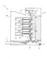
図1は本実施の形態に係る画像形成装置を示す概略構成図、図2はそのフロントカバーを開放した状態を示す概略構成図である。
図1に示す画像形成装置10は、本体10a内に4つの色のプロセスカートリッジ30(30Y,30M,30C,30K)を縦方向に順に配列した所謂タンデム型である。また、各プロセスカートリッジ30の各々の対応した箇所に、記録用紙Pを下方から上方に略垂直に搬送する搬送路12が配置されている。そして、最下段(最上流)のプロセスカートリッジ30Yの更に下方(上流側)には、搬送路12を搬送されてトナー像が順に転写される記録用紙Pを収容するための給紙カセット13が配設されている。Embodiments of the present invention will be described below in detail with reference to the accompanying drawings.
FIG. 1 is a schematic configuration diagram showing an image forming apparatus according to the present embodiment, and FIG. 2 is a schematic configuration diagram showing a state in which the front cover is opened.
The
プロセスカートリッジ30(30Y,30M,30C,30K)は、搬送路12の上流側(図中下側)から順にイエロー(Y)のトナー像を形成するプロセスカートリッジ30Y、マゼンタ(M)のトナー像を形成するプロセスカートリッジ30M、シアン(C)のトナー像を形成するプロセスカートリッジ30C、ブラック(K)のトナー像を形成するプロセスカートリッジ30Kの順に配設されている。これらの各プロセスカートリッジ30は、トナーの色を除いて同様な構成となっており、以下、別個に説明する必要がある場合以外はプロセスカートリッジ30として説明する。プロセスカートリッジ30は、感光体ドラム(像保持体)14と、感光体ドラム14の周囲に順次配設されている各種の電子写真用デバイスとを一体的にカートリッジ化したものである。内蔵したトナーが消費されると、このプロセスカートリッジ30ごと新たなものに交換される。このプロセスカートリッジ30が、本実施の形態における本発明の収容物供給容器であり画像形成ユニットである。その構成については後に詳述する。 The process cartridge 30 (30Y, 30M, 30C, 30K) forms a yellow (Y) toner image in order from the upstream side (lower side in the figure) of the
プロセスカートリッジ30を挟んで搬送路12と反対の側には、各プロセスカートリッジ30に共通の露光装置15が配設されている。この露光装置15は、各色に対応した画像データに基づいて図示しない4つの半導体レーザを点灯駆動する。そして、この4つの半導体レーザからの光を図示しないポリゴンミラーで偏向走査し、図示しないfθレンズ及び複数枚の反射ミラーを介して感光体ドラム14上の露光ポイントに導くことで、感光体ドラム14上に光像を描くように構成されている。 An
各プロセスカートリッジ30の感光体ドラム14に対応した箇所には、搬送路12に沿って循環移動する搬送ベルト16が配設されている。この搬送ベルト16は、記録用紙Pを静電吸着し得るベルト素材にて構成され、一対からなる駆動ローラ17A及び従動ローラ17Bに掛け渡されている。また、搬送路12には、搬送ベルト16に記録用紙Pを静電吸着させるための吸着ローラ18が配設されている。 A
各プロセスカートリッジ30の感光体ドラム14と対応する搬送ベルト16の裏面側には、それぞれ転写ローラ19が配設されている。この転写ローラ19は、感光体ドラム14と搬送ベルト16上の記録用紙Pとを密着させて感光体ドラム14に形成されたトナー像を記録用紙Pに転写するためのものである。 A
最上段(最下流)プロセスカートリッジ30Kの更に上方(下流側)の搬送路12には、定着装置20が設けられている。本体10aの上部には、定着装置20によりトナー像が定着されて排出された記録用紙Pを収容するための排紙部21が本体10aと一体に設けられている。また、本体10aには、定着装置20によって片面が定着された記録用紙Pを表裏反転させて搬送路12に再度送り込むための反転用搬送路22が配置されている。 A fixing
画像形成装置10の本体10aには、図2に示すように、下端に設けた回動支点Jを中心に回動可能なフロントカバー25が設けられている。このフロントカバー25は、閉じた状態では本体10aと共に外部カバーとして機能する。すなわち、フロントカバー25は、給紙カセット13よりも上側でかつ画像形成装置10の手前側の側壁部を構成する。 As shown in FIG. 2, the
フロントカバー25には、搬送ベルト16、駆動ローラ17A、従動ローラ17B、吸着ローラ18、転写ローラ19及び反転用搬送路22が取り付けられている。したがって、フロントカバー25を開けると、これらの部品が随伴して本体10a側から離間する。このため、フロントカバー25を開けることでプロセスカートリッジ30が露出し、また、搬送路12へのユーザによるアクセスが容易になる。 The
ここで、各プロセスカートリッジ30は、図2中プロセスカートリッジ30Kを例として示すように、各々本体10aに対して略水平方向に着脱自在に装着されている。このため、本体10aのフロントカバー25を開けることにより、各プロセスカートリッジ30の着脱操作を行うことが可能になる。なお、図示しないセット検出センサがプロセスカートリッジ30の各々のセット状態を検出し、その検出結果を図示しない制御装置に出力する。
このように、フロントカバー25を開放することで、プロセスカートリッジ30を露出させて交換することができる。また、感光体ドラム14を露出した状態にして紙詰まりに対処(ジャムクリア)することができる。Here, each
Thus, by opening the
そして、上記のごとき構成の画像形成装置10は、下記のごとく作用して画像形成を行う。
まず、図示しない画像読取装置(スキャナ)や図示しないコンピュータ装置等から画像データが画像形成装置10に入力されると、図示しない画像処理装置によって所定の画像処理を施した後、各色(YMCK)の画像データとして露光装置15に出力する。The
First, when image data is input to the
露光装置15は、入力された各色の画像データに応じて各半導体レーザから出射された露光ビームを、プロセスカートリッジ30の感光体ドラム14に照射する。各プロセスカートリッジ30では、露光によって感光体ドラム14に形成された静電潜像をそれぞれの色のトナーで現像してトナー像化する。
ついで、各プロセスカートリッジ30の各感光体ドラム14上に形成されたトナー像を、各転写ローラ19と当接する転写部で、カセット給紙部26から吸着ローラ18の作用によって搬送ベルト16に吸着された状態で供給される記録用紙Pに順次重畳して転写する。
そして、トナー像が静電転写された記録用紙Pを、搬送ベルト16に静電吸着した状態で定着装置20に搬送し、定着装置20による熱および圧力による定着処理によってトナー像を定着した後、画像形成装置10の上部に設けられた排紙部21に排出する。これによって、一連の画像形成プロセスが終了する。The
Next, the toner image formed on each
Then, the recording paper P on which the toner image is electrostatically transferred is conveyed to the fixing
つぎに、プロセスカートリッジ30について詳細に説明する。
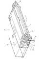
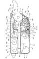
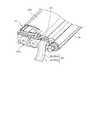
図3はプロセスカートリッジ30の外観斜視図、図4はそのA−A断面図である。
本実施の形態におけるプロセスカートリッジ30の外形形状は、図3に示すように平たい直方体状を呈している。大きくは上下二層に分かれており、その間が露光装置15からの露光ビームが通る光路空間となっている。
プロセスカートリッジ30は、感光体ドラム14と、帯電装置31と、現像装置32と、除電装置33およびクリーニング装置34を備えている。さらに、プロセスカートリッジ30は、サブトナー補給ユニット35と把手36とを備えている。
クリーニング装置34とサブトナー補給ユニット35とは上層部分に、現像装置32は下層部分にそれぞれ構成される。また、感光体ドラム14と帯電装置31とは上下層の間に位置している。
なお、以下、感光体ドラム14の軸方向を左右、これと直交する水平方向を前後、前後左右と直交する方向を上下として説明する。Next, the
FIG. 3 is an external perspective view of the
The outer shape of the
The
The
In the following description, the axial direction of the
感光体ドラム14は回転可能に配設されており、図示しない駆動モータによって図中矢印で示す方向に回転駆動される。感光体ドラム14の外周面には図示しないが感光層が形成されている。この感光体ドラム14の周囲に、帯電装置31、現像装置32、除電装置33およびクリーニング装置34が図中矢印で示すその回転方向に沿って配設されている。そして、感光体ドラム14の回転に伴って、その周面の感光体を、帯電装置31が帯電させ、現像装置32が前述の露光装置15によって形成された静電潜像をトナー像化する。また、除電装置33がトナー像を記録用紙に転写した後の感光体の帯電履歴を消去し、クリーニング装置34が感光体上に残存するトナーを機械的に除去する。 The
以下、これらプロセスカートリッジ30の各機構部の構成を説明する。
帯電装置31は、感光体ドラム14に接触配置される帯電ロール31aと、帯電ロール31aに接触配置される帯電クリーナ31bとを備える。帯電ロール31aは回転可能に取り付けられており、感光体ドラム14の回転に伴って従動回転する。そして、帯電ロール31aには、図示しない電源により感光体ドラム14を所定の電位(本実施の形態では負極性)に帯電させるための帯電バイアスが印加される。また、帯電クリーナ31bは、回転可能なロール部材あるいはブラシ部材等によって構成され、帯電ロール14の回転に伴って従動回転する。そして、帯電クリーナ31bは、感光体ドラム14から帯電ロール31aに転移付着したトナー等の異物を除去する。Hereinafter, the structure of each mechanism part of the
The charging
除電装置33は、感光体ドラム14の軸方向に向かって伸びる透明のロッド部材33aと、ロッド部材33aを保持するフレーム33bと、ロッド部材33aの軸方向端面に対向配置されるLED(図示せず)とを備える。ロッド部材33aは例えばプラスチック等にて構成され、外周面の軸方向に直交する方向に複数の溝が形成されている。 The
クリーニング装置34は、クリーニングブレード34aと、ブラケット34bと、トナー回収機構34cとを備える。クリーニングブレード34aは感光体ドラム14の軸方向に沿って取り付けられる短冊状の部材であり、例えばウレタンゴム等にて構成される。また、クリーニングブレード34aは、感光体ドラム14の回転方向と対向する方向に圧接配置される。そして、クリーニングブレード34aは、ブラケット34bを介してクリーニング装置34のハウジングに固定されている。トナー回収機構34cは、軸34dを中心に回転可能に配設されるアーム34eと、このアーム34eの自由端側に装着される掻き取り部材34fとを備える。 The
サブトナー補給ユニット35は、トナーを収容するサブトナー収容室35a内に、第1サブアジテータ35bと第2サブアジテータ35cとが設けられている。そして、このサブトナー補給ユニット35は、接続通路66を介してメイントナー補給ユニット60と接続されている。接続通路66は、露光装置15による露光ビームの光路の邪魔とならないように、プロセスカートリッジ30の図中奥側の位置に配設されている。
また、把手36はプロセスカートリッジ30の装着時あるいは交換時にユーザによる操作性を向上させると共に、揺動操作によってプロセスカートリッジ30を所定位置に固定する機能を有しているものである。The sub
The
つぎに、現像装置32について詳細に説明する。
現像装置32は、感光体ドラム14との対向部に開口部42を有するハウジング41内に、感光体ドラム14上の静電潜像をトナーで現像する現像ユニット部40と、この現像ユニット部40にトナーを補給するメイントナー補給ユニット60とが、水平方向に一体化して構成されている。また、上記サブトナー補給ユニット35も、現像装置32の一部を構成し、後述するようにメイントナー補給ユニット60にトナーを補給する。なお、この現像装置32は、トナーおよびキャリアを含む現像剤を用いる二成分方式のものである。
本実施の形態では、現像ユニット部40は感光体ドラム14の斜め下側に位置しており、ハウジング41に形成された開口部42は上向きとなっている。Next, the developing
The developing
In the present embodiment, the developing
ハウジング41は、下部ハウジング41aと、この下部ハウジング41aに嵌め合わせられる上部ハウジング41bと、下部ハウジング41aおよび上部ハウジング41bの内側で両者に取り付けられるサブハウジング41cとから成る。
サブハウジング41cは、下部ハウジング41aの上面との間にトナー補給室64を形成し、また、その上面に垂立形成された仕切り壁61aが、上部ハウジング41bの下面に嵌合してハウジング41の内部を現像ユニット部40(攪拌域47)とメイントナー補給ユニット60(トナー収容室61)とに仕切っている。
また、上部ハウジング41bの下面には、仕切り壁61aの現像ユニット部40側に隣接して現像剤室70が形成されている。この現像剤室70は、前後に所定間隔で垂下形成された二条の壁板41dと左右方向両端部の側板41e(後述する図7参照)とによって矩形の枠状に突出しており、攪拌域47の上側に位置して下側に開口(開口部71)している。この現像剤室70が、本実施の形態における本発明の収容物を収容する容器の一つであり、第一又は第二の粉体収容部の一方である。また、開口部71が供給開口部である。The
The sub-housing 41c forms a
Further, a
また、現像ユニット部40は、現像ロール43、一対のオーガ(供給オーガ44、攪拌オーガ45)と、層厚規制部材50とを備えている。
現像ロール43は、ハウジング41の開口部42に面した部位に取り付けられている。この現像ロール43は、内部に固定配設されるマグネットロール43aと、このマグネットロール43aの外周面に回転可能に配設される現像スリーブ43bとから成り、現像スリーブ43bは図示しない電源により所定の現像バイアスが印加され、図示しない駆動機構によって回転駆動される。Further, the developing
The developing
供給オーガ44および攪拌オーガ45は、ハウジング41内の現像ロール43の背面側下部に配設されている。
現像ロール43の背面側は、下部ハウジング41aに立設された仕切り壁48によって、供給域46と攪拌域47とに仕切られている。なお、仕切り壁48は左右両端部の所定範囲には設けられておらず、その部分で供給域46と攪拌域47との間で現像剤の流通が可能となっている。この供給域46が、本実施の形態における本発明の供給空間である。The
The rear side of the developing
供給オーガ44は現像ロール43に近い側である供給域46に配設され、攪拌オーガ45は供給域46と仕切り壁48を挟んでメイントナー補給ユニット60側の攪拌域47に配設されている。
層厚規制部材50は、現像ロール43の図中左斜め上方のハウジング41内に設けられている。この層厚規制部材50は、現像ロール43の軸方向に沿って、現像ロール43に対し一定のギャップを形成する。この層厚規制部材50は円柱状のシャフトにて構成されており、現像ロール43上に保持された現像剤を所定厚さに規制する。The
The layer
メイントナー補給ユニット60は、サブハウジング41cに立設された仕切り壁61aによって現像ユニット部40に対して仕切られたトナー収容室61と、サブハウジング41cと下部ハウジング41aとの間に形成されたトナー補給室64とを備えている。トナー収容室61の内部には、第1アジテータ62と、第2アジテータ63とが設けられており、また、トナー補給室64には補給オーガ65が設けられている。このトナー収容室61が、本実施の形態における本発明の収容物を収容する容器の一つであり、第一又は第二の粉体収容部の一方である。 The main
サブハウジング41cの図中奥側には、トナー収容室61とトナー補給室64とを連通接続するトナー搬入口67が形成される。また、サブハウジング41cの図中手前側には、トナー補給室64と攪拌域47とを連通接続するトナー補給口68が形成される。これにより、トナー収容室61に収容されたトナーを、トナー搬入口67、トナー補給室64、トナー補給口68を介して現像ユニット部40(供給域46)に供給し得るようになっている。このトナー補給口68が、本実施の形態における本発明の供給開口部である。 A toner carry-in
上記のごとく構成された現像装置32は、画像形成時において下記のごとく作用する。
現像ユニット部40では、供給オーガ44が供給域46において図中奥側から手前側に向けて現像剤を搬送し、攪拌オーガ45が攪拌域47において図中手前側から奥側に向けて現像剤を搬送する。供給域46および攪拌域47は上述したように長手方向両端側で連通接続されているため、現像剤はハウジング41内で攪拌されながら循環搬送されることになる。このとき、キャリアは正の帯電極性を有し、トナーは負の帯電極性を有している。このため、攪拌搬送にともなって現像剤中のトナー及びキャリアが互いに摩擦され、キャリアは正極性に帯電し、トナーは負極性に帯電する。The developing
In the developing
そして、攪拌搬送される現像剤が現像ロール43と対向する供給域46に搬送されると、マグネットロール43aに設けられた磁極の磁力により、現像剤中のキャリアが磁気的に吸引され、現像スリーブ43b上にキャリアが転移付着する。このとき、正極性に帯電したキャリアには負極性に帯電したトナーが静電吸着しているため、キャリアに付随してトナーも現像スリーブ43b上に転移付着する。したがって、現像スリーブ43b上には、トナー及びキャリアを含む現像剤が付着することになる。そして、現像スリーブ43b上の現像剤は、現像スリーブ43bの回転およびマグネットロール43aの磁力によって現像スリーブ43b上に保持された状態で搬送され、層厚規制部材50によって所定の厚さに規制されて、感光体ドラム14と対向する開口部42まで運ばれる。 When the developer to be stirred and conveyed is conveyed to the
現像スリーブ43bには図示しない電源から所定の現像バイアスが印加されており、これによって感光体ドラム14と近接する現像領域において、現像スリーブ43b上の現像剤層より感光体ドラム14上に形成された静電潜像にトナーが転移し、可視像化(トナー像化)する。
ハウジング41の開口部42を通過し現像を終了した現像スリーブ43b上の現像剤層は、マグネットロール43aの同極性の磁極間に形成される反発磁界によって離脱して供給域46に落下する。供給域46に落下した現像剤は、再び供給オーガ44および攪拌オーガ45によって攪拌搬送され、次の現像作用に供される。A predetermined developing bias is applied to the developing
The developer layer on the developing
このように、現像ユニット部40では、感光体ドラム14上の静電潜像を現像して可視像化することにより、現像剤に占めるトナーの割合(トナー濃度)が徐々に低下していく。このため、本実施の形態では、メイントナー補給ユニット60から、トナー濃度が低下した現像ユニット部40に新たなトナーを補給する。
メイントナー補給ユニット60から現像ユニット部40へのトナーの補給は、メイントナー補給ユニット60のトナー収容室61内のトナーを、第1アジテータ62と第2アジテータ63とがトナー搬入口67を介してトナー補給室64に供給し、トナー補給室64内のトナーを補給オーガ65が搬送してトナー補給口68を介して現像ユニット部40の攪拌域47に供給する。このようにして現像ユニット部40の攪拌域47に補給されたトナーは、既に現像ユニット部40内に存在する現像剤とともに攪拌オーガ45によって攪拌搬送され、これら現像剤と新たに供給されたトナーとが攪拌混合された状態で攪拌域47から供給域46に搬送され、現像に供されるものである。As described above, in the developing
Toner is replenished from the main
また、トナー収容室61に収容されたトナーが現像ユニット部40に供給されて減少すると、サブトナー補給ユニット35からその収容するトナーが接続通路66を介して補給される。
このようにして、現像ユニット部40でのトナーの消費に伴って、トナーをメイントナー補給ユニット60から補給し、また、メイントナー補給ユニット60にサブトナー補給ユニット35から補給するようになっている。これにより、プロセスカートリッジ30の寿命が尽きるまでの間、現像ユニット部40における現像剤中のトナー濃度をほぼ一定に維持することができるものである。When the toner stored in the
In this way, as the toner in the developing
ここで、プロセスカートリッジ30は、単独で梱包されて輸送され、たとえばユーザによって画像形成装置10の本体10aに装着されるようになっている。
そのプロセスカートリッジ30が供給される態様では、現像装置32の内部に、キャリアとトナーとが所定の比率で混合された現像剤と、補給用のトナーとが、それぞれ漏洩することのない状態で収容されている。この現像剤と補給用のトナーとが、本実施の形態における本発明の収容物であり第一又は第二の粉体である。
つぎに、この配送時における現像剤とトナーの収容構造、および画像形成装置10の本体10aに装着する際に現像剤とトナーを供給可能とする構成について、前述の図4と下記の各図面に基づいて説明する。Here, the
In the aspect in which the
Next, the developer and toner storage structure at the time of delivery, and the configuration in which the developer and toner can be supplied when mounted on the
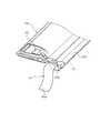
図5は下部ハウジング41aの斜視図、図6はサブハウジング41cを斜め前方(現像ユニット部40)側から見た斜視図、図7は上部ハウジング41bを天地反転させて見た斜視図である。なお、下部ハウジング41a、上部ハウジング41bおよびサブハウジング41cは、一体に組み立てられてハウジング41を構成しており、図5乃至図7は説明のための図であって、実際にこのように分解し得ることを示しているものではない。さらに、図8は上部ハウジング41bの端部の斜視図、図9は下部ハウジング41aの端部の斜視図、図10は下部ハウジング41aに上部ハウジング41bが組み合わされた状態の端部の斜視図である。 5 is a perspective view of the
現像剤を収容する現像剤室70は、前述のごとく上部ハウジング41bの下面に、二条の壁板41dと左右方向両端部の側板41eとによって囲まれた矩形の枠状に形成されており、攪拌域47の上側に位置して下側の開口部71で開口している。この現像剤室70に現像剤が収容され、開口部71が図4および図7に示すようにシール部材としての現像剤シールテープ81によって閉ざされている。 As described above, the
また、メイントナー補給ユニット60とサブトナー補給ユニット35とにはトナーが充填され、トナー補給室64と現像ユニット部40(攪拌域47)とを連通させるトナー補給口68が、図4および図6に示すようにサブハウジング41cの現像ユニット部40側の面に接着されたシール部材としてのトナーシールテープ82によって閉ざされている。
つまり、プロセスカートリッジ30が供給される状態では、現像装置32の攪拌域47および供給域46にトナーや現像剤は入っていない空の状態であり、現像剤シールテープ81を剥離することで、開口部71が開放して現像剤室70が攪拌域47を介して供給空間としての供給域46と連通し、トナーシールテープ82を剥離することでトナー補給口68が開放して攪拌域47を介して供給域46と連通し、はじめて供給域46に現像剤およびトナーが供給され得るようになっている。Further, a
That is, in the state where the
本実施の形態では、現像剤室70の開口部71は水平より僅かにトナー補給室64に向かうように傾斜しており、トナー補給口68は開口部71の斜め下方に位置し、僅かに上向きに傾斜してはいるが、両者は90度に近い角度を成している。
現像剤シールテープ81およびトナーシールテープ82は、樹脂テープの一面に熱溶融層が形成されたもので、その接着面(熱溶融層が形成された面)を被接着部(開口部71およびトナー補給口68)に当接させて表面側(熱溶融層が形成されない側)から熱板で加熱加圧することで、熱粘着材層が溶融して被接着部材に接着する。その接着力は、内部の現像剤又はトナーの漏れがなく、しかも容易に引き剥がすことができるように設定される。In this embodiment, the
The
現像剤室70の開口部を密封する現像剤シールテープ81は、図7に示すように、現像剤室70を形成する壁板41dおよび側板41eの端面に貼り付けられて開口部71を閉ざしている。その長さは開口部71の長手方向の二倍以上あり、先端が開口部71の一方の端部に対応し、開口部71の他端で折り返されて、自由端は図8に示すように上部ハウジング41bの側端より外側に達している。この自由端が操作部81aとなっている。これが、本実施の形態における本発明の第一又は第二の操作部の一方である。
一方、トナー補給口68を密封するトナーシールテープ82は、図6に示すように、トナー補給口68の周縁に貼り付けられてそのトナー補給口68を閉ざしている。シールテープ82は、その先端がトナー補給口68の一方の端部に対応し、トナー補給口68の端部で折り返されて自由端が図9に示すように下部ハウジング41aの外側に達している。この自由端が操作部82aとなっている。これが、本実施の形態における本発明の第一又は第二の操作部の一方である。As shown in FIG. 7, the
On the other hand, as shown in FIG. 6, the
ここで、現像剤シールテープ81とトナーシールテープ82とは、角度は異なるものの配設部位は近接しているために両者の自由端はほぼ同じ位置となり、また、両者の接着面は角度を有して対向することとなる。そして、現像剤シールテープ81の下側(接着面側)にトナーシールテープ82が接着面を対向させて重なった状態で、現像剤室70の側板41eと下部ハウジング41aの側縁の内面の間を通り、図10に示すように下部ハウジング41aと上部ハウジング41bとの間に形成されたスリット41fを介してハウジング41の側端から外側に導き出されている。
スリット41fは、現像剤室70の開口部71の端面と略等しい角度に設定されており、現像剤シールテープ81はそのままの姿勢で導き出される。一方、開口部71に対して角度を有するトナー補給口68を塞ぐトナーシールテープ82は現像剤室70の側板41eによって規定される経路中で捻られて現像剤シールテープ81に重なって導き出される。Here, although the
The
このように現像剤シールテープ81とトナーシールテープ82とが、接着面を対向させて重なった状態でスリット41fを通して導き出されるため、接着面でない表面が外部と接触することとなり、引き抜き操作する際に円滑な摺動移動が可能となる。
なお、現像剤シールテープ81とトナーシールテープ82との幅は、閉ざすべき対象(開口部71,トナー補給口68)の幅より広く設定されることは勿論であるが、その要因とは別に、上側に位置する現像剤シールテープ81が下側に位置するトナーシールテープ82より所定量広く設定されている。As described above, the
Of course, the widths of the
そして、現像剤シールテープ81とトナーシールテープ82とは、ハウジング41の外側に至った自由端(操作部81a,82a)で接着され、重合テープ部80として一枚に纏められている。その接着は、接着面(熱溶融層)が対向していることから熱溶着であっても良い。また、別に両面接着テープや接着剤を用いても良く、その場合、熱溶融層同士を接着することとなるために剥がれ難い良好な接着が可能となる。これらが本実施の形態における本発明の連結手段および貼り付け手段である。
また、上側に位置する現像剤シールテープ81を下側に位置するトナーシールテープ82より幅広としたため、トナーシールテープ82にたとえば両面接着テープを貼り付けて現像剤シールテープ81に接着すれば、現像剤シールテープ81に対してトナーシールテープ82がズレて接着された場合でも、トナーシールテープ82の側縁は現像剤シールテープ81に隠れて表面側からは見えないために見苦しくはならず、従って、接着作業に際して繊細な注意は不要となる。The
Further, since the
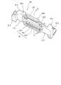
ハウジング41の側端から外側に導き出されて、現像剤シールテープ81とトナーシールテープ82とが接着されて一枚となった重合テープ部80は、図3に示すように、保持部材90によってプロセスカートリッジ30の側面に装着されている。ハウジング41の側面には、突出する軸受け等の突起物を覆って平坦な側面を形成するためのカバー37が装着されており、保持部材90はこのカバー37の外面に係合して固定されている。 As shown in FIG. 3, the superposed
図11は自由状態の保持部材90の外観斜視図、図12はその作用を説明する断面図であって(a)は図11のB−B断面に相当し、(b)は重合テープ部80に係合した状態を示す。
保持部材90は、合成樹脂による成形品であり、左右両端の固定部91L,91Rの間に、テープ係合部92を備えている。
テープ係合部92は、それぞれ左右の固定部91L,91Rの間をつなぐように設けられた、支持板92Aと、ガイドバー92Bとから成る。FIG. 11 is an external perspective view of the holding
The holding
The
支持板92Aは、平板状で板面を図中上下方向として形成されており、上下方向所定位置に、左右方向ほぼ全域に亘る長さの係合スリット92Cが開口形成されている。この係合スリット92Cの下側の内面は山形に形成されている。
また、支持板92Aの上縁に、可撓部92Dを介して係合部92Eが延設されている。係合部92Eの先端には、係合突条92Fが突設されている。そして、図12(a)中に矢印で示すように可撓部92Dを弾性屈曲させることで、係合部92Eが係合スリット92Cに嵌合し、先端の係合突条92Fが係合スリット92Cの山形の内面に係合するようになっている。可撓部92Dは、支持板92Aの両端部のみに所定幅で設けられており、支持板92Aと係合部92Eとの間に重合テープ部80を挿通し得るようになっている。The
Further, an engaging
ガイドバー92Bは、支持板92Aの斜め下側に、支持板92Aとの間に重合テープ部80を挿通可能な隙間を有して設けられている。
このような構成のテープ係合部92は、図12(a)に示すように、重合テープ部80を、支持板92Aと係合部92Eとの間を図中右側から左側に通し、さらに、支持板92Aの前面側(図中左側)から支持板92Aとガイドバー92Bの間を下側に通した後、可撓部92Dを屈曲させて係合部92Eを係合スリット92Cに係合させることで、(b)に示すように係合部92Eが重合テープ部80を噛み込んで係合スリット92Cに係合する。これにより、保持部材90が重合テープ部80に固定される。この保持部材90と重合テープ部80の係合は、保持部材90を支持して重合テープ部80の先端を強く引っ張れば、重合テープ部80によって係合部92Eが係合スリット92Cから押し出され、解除することができる。The
As shown in FIG. 12A, the
左右の固定部91L,91Rは、カバー37の側面に当接する当接部91Aと、カバー37に形成された係合孔に係合する係合固定部91Bとを備えている。また、一方の固定部91Lには、干渉突起91Cが外側に所定高さに突出形成されている。
そして、上記のごとく構成された保持部材90は、テープ係合部92で重合テープ部80に装着され、プロセスカートリッジ30のカバー37に係合固定される。これにより、図3に示すように重合テープ部80をプロセスカートリッジ30の側面に沿わせて収まりを良くすることができる。なお、その際、重合テープ部80の先端は図中に示すように保持部材90より所定量下側に突出させる。また、保持部材90のカバー37への係合強度は、容易に外すことのできる程度に設定される。The left and right fixing portions 91 </ b> L and 91 </ b> R include a contact portion 91 </ b> A that contacts the side surface of the
The holding
このような構成によれば、保持部材90の下側に突出する重合テープ部80の先端を支持してプロセスカートリッジ30から離間する側に引っ張ることで、保持部材90がカバー37(プロセスカートリッジ30)から外れ、その後、二本のシールテープ81,82を同時に引き剥がして、現像剤室70の開口部とトナー補給口68とを同時に開放することができる。つまり、一度の引き剥がし操作で現像剤室70の開口部とトナー補給口68の開口とを容易且つ簡便に行えるものである。 According to such a configuration, the holding
さらに、保持部材90がプロセスカートリッジ30(カバー37)に装着された状態では、保持部材90はプロセスカートリッジ30の側面に突出した状態で固定される。ここで、図3中に二点鎖線で示すように、画像形成装置10の本体10aの、プロセスカートリッジ30が装着される部位(装着開口部10b)の幅を、プロセスカートリッジ30のみの状態で挿入可能な大きさに設定しておく。これにより、保持部材90が装着された状態では、図2中にハッチングで示す装着開口部10bの周縁部に保持部材90が干渉し、プロセスカートリッジ30を本体10aに装着することができない。つまり、保持部材90を外して重合テープ部80(すなわちシールテープ81,82)を除去しないと、プロセスカートリッジ30を本体10aに装着できないようになっている。これにより、シールテープ81,82を剥がし忘れて装着することは無く、剥がし忘れたシールテープ81,82に起因する不具合を未然に防ぐことができるものである。 Further, when the holding
なお、本発明は、上記の実施の形態に限定されるものではなく、適宜変更可能なものである。たとえば、上記実施の形態では現像剤シールテープ81とトナーシールテープ82とはハウジング41の外側の自由端で接着されて重合テープ部80となっているが、接着することなく保持部材90によって一体化しても良い。つまり、保持部材90が連結手段を兼用するものである。
また、適用する画像形成装置も、実施の形態に記載の構成に限定されるものではない。In addition, this invention is not limited to said embodiment, It can change suitably. For example, in the above embodiment, the
Further, the image forming apparatus to be applied is not limited to the configuration described in the embodiment.
10…画像形成装置、10a…本体、10b…装着開口部(画像形成装置の装着部位)、14…感光体ドラム(像保持体)、30…プロセスカートリッジ(収容物供給容器,画像形成ユニット)、32…現像装置、46…供給域(供給空間)、68…トナー補給口(供給開口部)、70…現像剤室(容器,粉体収容部)、71…開口部(供給開口部)、81…現像剤シールテープ(シール部材)、82…トナーシールテープ(シール部材)、81a,82a…操作部、90…保持部材DESCRIPTION OF
Claims (5)
Translated fromJapanese静電潜像を形成する像保持体と、
第一の粉体と第二の粉体とで構成される現像剤を用いて前記静電潜像を顕像化する現像装置と、
前記第一の粉体と前記第二の粉体とを供給空間で混合して前記現像装置に供給する現像剤収容手段と、を備え、
前記現像剤収容手段は、
前記第一の粉体を収容し前記供給空間に向かって開口する第一の供給開口部を有する第一の粉体収容部と、
前記第一の供給開口部を閉ざす第一のシール部材と、
前記第二の粉体を収容し前記供給空間に向かって開口する第二の供給開口部を有する第二の粉体収容部と、
前記第二の供給開口部を閉ざす第二のシール部材と、
係合部と当該係合部が係合する被係合部とを有し当該係合部と当該被係合部とが前記第一のシール部材と前記第二のシール部材とを挟み込んで係合することにより当該第一のシール部材と当該第二のシール部材とを束ねるとともに、前記画像形成ユニットの外面に係合して固定されることで、束ねられた当該第一のシール部材と当該第二のシール部材とを当該画像形成ユニットの当該外面に保持する保持部材と
を備え、
前記第一のシール部材と前記第二のシール部材とを一度に操作して、前記第一の供給開口部と前記第二の供給開口部とを開放し得るとともに、当該第一のシール部材及び当該第二のシール部材の少なくとも一方が操作されることにより前記保持部材が前記画像形成ユニットの前記外面から外れるように構成されていることを特徴とする画像形成ユニット。An image forming unit configured to be detachable from the image forming apparatus main body,
An image carrier that forms an electrostatic latent image;
A developing device that visualizes the electrostatic latent image using a developer composed of a first powder and a second powder;
Developer containing means for mixing the first powder and the second powder in a supply space and supplying the developer to the developing device,
The developer containing means is
A first powder container having a first supply opening for accommodating the first powder and opening toward the supply space;
A first seal member for closing the first supply opening;
A second powder container having a second supply opening for accommodating the second powder and opening toward the supply space;
A second seal member for closing the second supply opening;
An engaging portion and an engaged portion with which the engaging portion engages, and the engaging portion and the engaged portion sandwich the first seal member and the second seal member and engage with each other. By combining, the first seal member and the second seal member are bundled, andby being engaged with and fixed to the outer surface of the image forming unit, the bundled first seal member and the second seal member a second sealing member and a holding member for holding tothe outer surface ofthe image forming unit,
The first seal member and the second seal member can be operated at a time to open the first supply opening and the second supply opening, and the first seal member and An image forming unit, wherein the holding member is configured to be detached from the outer surface of the image forming unit when at least one of the second seal members is operated.
前記保持部材は、前記係合孔に係合することにより固定される係合固定部を備え、
前記係合固定部が前記係合孔に係合することにより、前記保持部材が前記画像形成ユニットの前記外面に保持されることを特徴とする請求項1記載の画像形成ユニット。The image forming unit includes an engagement hole formed in the outer surface,
The holding member includes an engagement fixing portion that is fixed by engaging with the engagement hole,
The image forming unit according to claim 1, wherein the holding member is held on the outer surface of the image forming unit by the engagement fixing portion engaging with the engagement hole.
前記第二のシール部材は、前記第二の供給開口部から離れる側への移動操作によって当該第二の供給開口部を開放させる第二の操作部を備え、
前記第一の操作部の前記第一の供給開口部と対向する側の面と、前記第二の操作部の前記第二の供給開口部と対向する側の面とが向かい合い、同一部位を介して前記供給空間の外部に導き出されていることを特徴とする請求項1または2に記載の画像形成ユニット。The first seal member includes a first operation portion that opens the first supply opening by a moving operation away from the first supply opening.
The second seal member includes a second operation portion that opens the second supply opening portion by a moving operation away from the second supply opening portion,
The surface of the first operation portion facing the first supply opening and the surface of the second operation portion facing the second supply opening face each other and pass through the same portion. The image forming unit according to claim 1, wherein the image forming unit is led outside the supply space.
前記連結手段は、前記第一のシール部材と前記第二のシール部材とを貼り付ける貼り付け手段であることを特徴とする請求項1乃至3の何れかに記載の画像形成ユニット。A connecting means for connecting the first seal member and the second seal member;
4. The image forming unit according to claim 1, wherein the connecting unit is an attaching unit that attaches the first seal member and the second seal member. 5.
Priority Applications (5)
| Application Number | Priority Date | Filing Date | Title |
|---|---|---|---|
| JP2006128486AJP4946157B2 (en) | 2006-05-02 | 2006-05-02 | Image forming unit |
| US11/595,862US8023858B2 (en) | 2006-05-02 | 2006-11-13 | Material supplying container having sealing member, and image forming unit including same |
| AU2007200525AAU2007200525A1 (en) | 2006-05-02 | 2007-02-07 | Material supplying container and image forming unit |
| CN2007100792852ACN101067734B (en) | 2006-05-02 | 2007-02-16 | Material supplying container and image forming unit |
| AU2010202433AAU2010202433B2 (en) | 2006-05-02 | 2010-06-10 | Material supplying container and image forming unit |
Applications Claiming Priority (1)
| Application Number | Priority Date | Filing Date | Title |
|---|---|---|---|
| JP2006128486AJP4946157B2 (en) | 2006-05-02 | 2006-05-02 | Image forming unit |
Publications (2)
| Publication Number | Publication Date |
|---|---|
| JP2007298871A JP2007298871A (en) | 2007-11-15 |
| JP4946157B2true JP4946157B2 (en) | 2012-06-06 |
Family
ID=38661270
Family Applications (1)
| Application Number | Title | Priority Date | Filing Date |
|---|---|---|---|
| JP2006128486AExpired - Fee RelatedJP4946157B2 (en) | 2006-05-02 | 2006-05-02 | Image forming unit |
Country Status (4)
| Country | Link |
|---|---|
| US (1) | US8023858B2 (en) |
| JP (1) | JP4946157B2 (en) |
| CN (1) | CN101067734B (en) |
| AU (2) | AU2007200525A1 (en) |
Families Citing this family (12)
| Publication number | Priority date | Publication date | Assignee | Title |
|---|---|---|---|---|
| JP5250343B2 (en)* | 2008-08-27 | 2013-07-31 | 京セラドキュメントソリューションズ株式会社 | Image forming apparatus and image forming unit |
| JP5423065B2 (en)* | 2009-03-09 | 2014-02-19 | 富士ゼロックス株式会社 | Seal member detection apparatus, image forming apparatus, and seal member detection program |
| JP5431423B2 (en) | 2011-07-08 | 2014-03-05 | 東芝テック株式会社 | Decolorizable toner and method for producing the same |
| KR101580841B1 (en)* | 2011-11-17 | 2015-12-30 | 삼성전자주식회사 | Devoloping device and image forming apparatus using the same |
| CN104678734B (en)* | 2013-12-02 | 2022-05-06 | 纳思达股份有限公司 | Method for repairing process cartridge, process cartridge obtained after repair, and sealing stay for repair |
| US9996025B1 (en)* | 2017-03-02 | 2018-06-12 | Kabushiki Kaisha Toshiba | Cartridge, image forming apparatus and image forming method |
| JP6664139B2 (en) | 2018-02-26 | 2020-03-13 | キヤノン株式会社 | Developing device |
| JP7242917B2 (en)* | 2020-02-12 | 2023-03-20 | キヤノン株式会社 | developing device |
| JP7009528B2 (en)* | 2020-02-12 | 2022-01-25 | キヤノン株式会社 | Developer |
| CN114253110A (en)* | 2020-09-25 | 2022-03-29 | 江西亿铂电子科技有限公司 | Developing box |
| CN113515026A (en)* | 2021-06-16 | 2021-10-19 | 珠海天威飞马打印耗材有限公司 | Powder box without waste powder |
| JP2023142274A (en)* | 2022-03-24 | 2023-10-05 | 富士フイルムビジネスイノベーション株式会社 | Developing device and image forming apparatus |
Family Cites Families (26)
| Publication number | Priority date | Publication date | Assignee | Title |
|---|---|---|---|---|
| US4607938A (en)* | 1983-04-26 | 1986-08-26 | Canon Kabushiki Kaisha | Method and apparatus for forming a thin layer of developer |
| US4615608A (en)* | 1983-10-31 | 1986-10-07 | Canon Kabushiki Kaisha | Developing apparatus |
| JPS6193469A (en)* | 1984-10-12 | 1986-05-12 | Canon Inc | developing device |
| JPS6095561A (en)* | 1983-10-31 | 1985-05-28 | Canon Inc | Developing device |
| US4969557A (en)* | 1985-11-26 | 1990-11-13 | Ricoh Co., Ltd. | Toner cartridge |
| DE3816859A1 (en)* | 1988-05-18 | 1989-11-23 | Henkel Kgaa | MULTI-COMPONENT CASE |
| JP3071850B2 (en)* | 1991-04-16 | 2000-07-31 | 株式会社東芝 | Container device |
| JPH05188667A (en) | 1992-01-07 | 1993-07-30 | Canon Inc | Process cartridge and recorder |
| JPH05289502A (en)* | 1992-04-09 | 1993-11-05 | Ricoh Co Ltd | Toner cartridge |
| US5392947A (en)* | 1993-10-29 | 1995-02-28 | Chesebrough-Pond's Usa Co., Division Of Conopco, Inc. | Dental mouthwash product |
| JP3352569B2 (en)* | 1994-08-31 | 2002-12-03 | 株式会社リコー | Supply cartridge for two-component developer and supply device provided with the cartridge |
| JPH08202239A (en)* | 1995-01-20 | 1996-08-09 | Canon Inc | Image forming apparatus, process cartridge, developing device, and developer supply container |
| JPH10171233A (en)* | 1996-10-07 | 1998-06-26 | Canon Inc | Developing cartridge and electrophotographic image forming apparatus |
| JP3083091B2 (en) | 1997-12-09 | 2000-09-04 | キヤノン株式会社 | Seal member for developer storage container, developer storage container, developing device, process cartridge, and image forming apparatus |
| JP2954140B2 (en) | 1998-02-27 | 1999-09-27 | 新潟日本電気株式会社 | Toner cartridge |
| JP2000187379A (en)* | 1998-12-22 | 2000-07-04 | Ricoh Co Ltd | Developing device and image forming device |
| JP3943761B2 (en)* | 1999-06-08 | 2007-07-11 | キヤノン株式会社 | Process cartridge and electrophotographic image forming apparatus |
| JP3499506B2 (en) | 2000-05-22 | 2004-02-23 | シャープ株式会社 | Toner cartridge |
| JP4132728B2 (en)* | 2001-06-08 | 2008-08-13 | 株式会社リコー | Developing device, image forming apparatus, and process cartridge |
| JP2003173076A (en) | 2001-12-07 | 2003-06-20 | Canon Inc | Developing device and developing cartridge |
| JP2003195614A (en) | 2001-12-28 | 2003-07-09 | Canon Inc | Color developing cartridge and color electrophotographic image forming apparatus |
| US6679594B2 (en)* | 2002-02-16 | 2004-01-20 | Hewlett-Packard Development Company, Lp. | Imaging media cartridge having a reserve chamber |
| US6669048B2 (en)* | 2002-03-12 | 2003-12-30 | Basf Corporation | Neck apparatus and closure system for a multi-compartment bottle |
| US20050077316A1 (en) | 2003-10-08 | 2005-04-14 | Roberts Thomas C. | Multiple-opening container and method |
| US20050249519A1 (en)* | 2004-05-06 | 2005-11-10 | Rec & Assign | Cartridge for toner having removable seal |
| JP4606279B2 (en) | 2004-10-19 | 2011-01-05 | シャープ株式会社 | Waste developer collection container for image forming apparatus |
- 2006
- 2006-05-02JPJP2006128486Apatent/JP4946157B2/ennot_activeExpired - Fee Related
- 2006-11-13USUS11/595,862patent/US8023858B2/enactiveActive
- 2007
- 2007-02-07AUAU2007200525Apatent/AU2007200525A1/ennot_activeAbandoned
- 2007-02-16CNCN2007100792852Apatent/CN101067734B/enactiveActive
- 2010
- 2010-06-10AUAU2010202433Apatent/AU2010202433B2/enactiveActive
Also Published As
| Publication number | Publication date |
|---|---|
| CN101067734B (en) | 2010-09-01 |
| AU2007200525A1 (en) | 2007-11-22 |
| AU2010202433B2 (en) | 2011-07-28 |
| US20070258727A1 (en) | 2007-11-08 |
| AU2010202433A1 (en) | 2010-07-01 |
| US8023858B2 (en) | 2011-09-20 |
| CN101067734A (en) | 2007-11-07 |
| JP2007298871A (en) | 2007-11-15 |
Similar Documents
| Publication | Publication Date | Title |
|---|---|---|
| JP4946157B2 (en) | Image forming unit | |
| JP4437476B2 (en) | Toner supply device, image forming apparatus, and toner supply method | |
| CN101046657B (en) | Toner replenishing device, image forming device, and toner shortage detection method | |
| JP4208905B2 (en) | Image forming apparatus | |
| CN101206442B (en) | Developer transport device, developing device, and image forming apparatus | |
| JP4376232B2 (en) | Toner container and toner supply device using the same | |
| JP2009036920A (en) | Image forming apparatus | |
| JP4522381B2 (en) | Toner container and toner supply device using the same | |
| CN100492203C (en) | developer supply container | |
| JP4440901B2 (en) | Image forming apparatus | |
| CN100517112C (en) | Toner Container and Toner Filling Method | |
| JP5273263B2 (en) | Developer container, developing device, process unit, and image forming apparatus | |
| JP2007271884A (en) | Toner supply device and image forming apparatus using the same | |
| JP2011008144A (en) | Toner supply device and toner supply mechanism | |
| JP4356674B2 (en) | Developer housing case, process cartridge having the same, and image forming apparatus | |
| JP5168556B2 (en) | Containment supply container and image forming apparatus | |
| JP2010217238A (en) | Developing device and image forming device | |
| JP6033596B2 (en) | Image forming apparatus and toner supply device | |
| JP3379660B2 (en) | Image forming device | |
| JP6025417B2 (en) | Image forming apparatus and toner supply device | |
| AU2007201512B2 (en) | Container, stored material supply container, image forming unit and image forming apparatus | |
| JPH07160106A (en) | Image forming device | |
| JP2007279337A (en) | Toner supply device and image forming apparatus using the same | |
| JP2000181211A (en) | Image forming device |
Legal Events
| Date | Code | Title | Description |
|---|---|---|---|
| A621 | Written request for application examination | Free format text:JAPANESE INTERMEDIATE CODE: A621 Effective date:20090210 | |
| A977 | Report on retrieval | Free format text:JAPANESE INTERMEDIATE CODE: A971007 Effective date:20110421 | |
| A131 | Notification of reasons for refusal | Free format text:JAPANESE INTERMEDIATE CODE: A131 Effective date:20110426 | |
| A521 | Request for written amendment filed | Free format text:JAPANESE INTERMEDIATE CODE: A523 Effective date:20110621 | |
| A131 | Notification of reasons for refusal | Free format text:JAPANESE INTERMEDIATE CODE: A131 Effective date:20110712 | |
| A521 | Request for written amendment filed | Free format text:JAPANESE INTERMEDIATE CODE: A523 Effective date:20110909 | |
| TRDD | Decision of grant or rejection written | ||
| A01 | Written decision to grant a patent or to grant a registration (utility model) | Free format text:JAPANESE INTERMEDIATE CODE: A01 Effective date:20120207 | |
| A01 | Written decision to grant a patent or to grant a registration (utility model) | Free format text:JAPANESE INTERMEDIATE CODE: A01 | |
| A61 | First payment of annual fees (during grant procedure) | Free format text:JAPANESE INTERMEDIATE CODE: A61 Effective date:20120220 | |
| FPAY | Renewal fee payment (event date is renewal date of database) | Free format text:PAYMENT UNTIL: 20150316 Year of fee payment:3 | |
| R150 | Certificate of patent or registration of utility model | Ref document number:4946157 Country of ref document:JP Free format text:JAPANESE INTERMEDIATE CODE: R150 | |
| S533 | Written request for registration of change of name | Free format text:JAPANESE INTERMEDIATE CODE: R313533 | |
| R350 | Written notification of registration of transfer | Free format text:JAPANESE INTERMEDIATE CODE: R350 | |
| LAPS | Cancellation because of no payment of annual fees |