JP4943543B2 - MAP DISPLAY DEVICE, MAP DISPLAY METHOD, MAP DISPLAY PROGRAM, AND RECORDING MEDIUM - Google Patents
MAP DISPLAY DEVICE, MAP DISPLAY METHOD, MAP DISPLAY PROGRAM, AND RECORDING MEDIUMDownload PDFInfo
- Publication number
- JP4943543B2 JP4943543B2JP2010534307AJP2010534307AJP4943543B2JP 4943543 B2JP4943543 B2JP 4943543B2JP 2010534307 AJP2010534307 AJP 2010534307AJP 2010534307 AJP2010534307 AJP 2010534307AJP 4943543 B2JP4943543 B2JP 4943543B2
- Authority
- JP
- Japan
- Prior art keywords
- map
- display
- angle
- overhead
- touch panel
- Prior art date
- Legal status (The legal status is an assumption and is not a legal conclusion. Google has not performed a legal analysis and makes no representation as to the accuracy of the status listed.)
- Expired - Fee Related
Links
Images


Classifications
- G—PHYSICS
- G09—EDUCATION; CRYPTOGRAPHY; DISPLAY; ADVERTISING; SEALS
- G09B—EDUCATIONAL OR DEMONSTRATION APPLIANCES; APPLIANCES FOR TEACHING, OR COMMUNICATING WITH, THE BLIND, DEAF OR MUTE; MODELS; PLANETARIA; GLOBES; MAPS; DIAGRAMS
- G09B29/00—Maps; Plans; Charts; Diagrams, e.g. route diagram
- G09B29/003—Maps
- G—PHYSICS
- G01—MEASURING; TESTING
- G01C—MEASURING DISTANCES, LEVELS OR BEARINGS; SURVEYING; NAVIGATION; GYROSCOPIC INSTRUMENTS; PHOTOGRAMMETRY OR VIDEOGRAMMETRY
- G01C21/00—Navigation; Navigational instruments not provided for in groups G01C1/00 - G01C19/00
- G01C21/26—Navigation; Navigational instruments not provided for in groups G01C1/00 - G01C19/00 specially adapted for navigation in a road network
- G01C21/34—Route searching; Route guidance
- G01C21/36—Input/output arrangements for on-board computers
- G01C21/3626—Details of the output of route guidance instructions
- G01C21/3635—Guidance using 3D or perspective road maps
- G01C21/3638—Guidance using 3D or perspective road maps including 3D objects and buildings
- G—PHYSICS
- G01—MEASURING; TESTING
- G01C—MEASURING DISTANCES, LEVELS OR BEARINGS; SURVEYING; NAVIGATION; GYROSCOPIC INSTRUMENTS; PHOTOGRAMMETRY OR VIDEOGRAMMETRY
- G01C21/00—Navigation; Navigational instruments not provided for in groups G01C1/00 - G01C19/00
- G01C21/26—Navigation; Navigational instruments not provided for in groups G01C1/00 - G01C19/00 specially adapted for navigation in a road network
- G01C21/34—Route searching; Route guidance
- G01C21/36—Input/output arrangements for on-board computers
- G01C21/3664—Details of the user input interface, e.g. buttons, knobs or sliders, including those provided on a touch screen; remote controllers; input using gestures
- G—PHYSICS
- G06—COMPUTING OR CALCULATING; COUNTING
- G06F—ELECTRIC DIGITAL DATA PROCESSING
- G06F3/00—Input arrangements for transferring data to be processed into a form capable of being handled by the computer; Output arrangements for transferring data from processing unit to output unit, e.g. interface arrangements
- G06F3/01—Input arrangements or combined input and output arrangements for interaction between user and computer
- G06F3/048—Interaction techniques based on graphical user interfaces [GUI]
- G06F3/0487—Interaction techniques based on graphical user interfaces [GUI] using specific features provided by the input device, e.g. functions controlled by the rotation of a mouse with dual sensing arrangements, or of the nature of the input device, e.g. tap gestures based on pressure sensed by a digitiser
- G06F3/0488—Interaction techniques based on graphical user interfaces [GUI] using specific features provided by the input device, e.g. functions controlled by the rotation of a mouse with dual sensing arrangements, or of the nature of the input device, e.g. tap gestures based on pressure sensed by a digitiser using a touch-screen or digitiser, e.g. input of commands through traced gestures
- G—PHYSICS
- G06—COMPUTING OR CALCULATING; COUNTING
- G06T—IMAGE DATA PROCESSING OR GENERATION, IN GENERAL
- G06T17/00—Three dimensional [3D] modelling, e.g. data description of 3D objects
- G06T17/05—Geographic models
- G—PHYSICS
- G09—EDUCATION; CRYPTOGRAPHY; DISPLAY; ADVERTISING; SEALS
- G09B—EDUCATIONAL OR DEMONSTRATION APPLIANCES; APPLIANCES FOR TEACHING, OR COMMUNICATING WITH, THE BLIND, DEAF OR MUTE; MODELS; PLANETARIA; GLOBES; MAPS; DIAGRAMS
- G09B29/00—Maps; Plans; Charts; Diagrams, e.g. route diagram
- G09B29/10—Map spot or coordinate position indicators; Map reading aids
Landscapes
- Engineering & Computer Science (AREA)
- Physics & Mathematics (AREA)
- Remote Sensing (AREA)
- Theoretical Computer Science (AREA)
- Radar, Positioning & Navigation (AREA)
- General Physics & Mathematics (AREA)
- Automation & Control Theory (AREA)
- Business, Economics & Management (AREA)
- Software Systems (AREA)
- Human Computer Interaction (AREA)
- Mathematical Physics (AREA)
- Geometry (AREA)
- Educational Administration (AREA)
- Educational Technology (AREA)
- General Engineering & Computer Science (AREA)
- Computer Graphics (AREA)
- Navigation (AREA)
- Instructional Devices (AREA)
Description
Translated fromJapaneseこの発明は、地図データを表示する地図表示装置、地図表示方法、地図表示プログラムおよび記録媒体に関する。ただし、この発明の利用は、上述した地図表示装置、地図表示方法、地図表示プログラムおよび記録媒体に限られない。 The present invention relates to a map display device that displays map data, a map display method, a map display program, and a recording medium. However, the use of the present invention is not limited to the above-described map display device, map display method, map display program, and recording medium.
従来、ナビゲーション装置などにおいて地図データを表示する際に、操作バーの操作つまみを上下することによって平面図から俯瞰図へと地図データの表示を切り替える技術が知られている(たとえば、下記特許文献1参照)。下記特許文献1では、地図操作バーにおいて操作つまみが一番上に位置している場合は、平面地図による道路地図を表示する。地図操作バーの操作つまみが画面下方向に移動されると、地図の表示形式を平面地図から俯瞰地図へと切り替え、俯瞰地図を表示する。さらに画面下方向に移動されると、それに応じて俯瞰地図の見下ろし角度や視点の高さを変化させ、先の方の地図範囲を表示する。操作つまみが一番下まで移動されると、俯瞰地図を表示する。 2. Description of the Related Art Conventionally, when displaying map data in a navigation device or the like, a technique for switching display of map data from a plan view to an overhead view by moving an operation knob of an operation bar up and down is known (for example, Patent Document 1 below). reference). In Patent Document 1 below, when the operation knob is located at the top of the map operation bar, a road map based on a planar map is displayed. When the operation knob of the map operation bar is moved downward on the screen, the map display format is switched from the planar map to the overhead map, and the overhead map is displayed. When the screen is further moved downward, the look-down angle of the overhead map and the height of the viewpoint are changed accordingly, and the earlier map range is displayed. When the operation knob is moved to the bottom, an overhead map is displayed.
また、タッチパネル式の入力デバイスを備える情報処理装置において、タッチ強度を2段階に判別し、それぞれの強度によるタッチを異なる操作入力として処理する技術が知られている(たとえば、下記特許文献2参照)。 In addition, in an information processing apparatus including a touch panel type input device, a technique is known in which touch intensity is determined in two stages, and touches of the respective intensities are processed as different operation inputs (for example, see
しかしながら、上述した特許文献1では、操作バーを用いて地図データの表示態様を変更している。このため、操作バーを表示画面上に表示する必要があり、地図データの表示領域が狭くなってしまうという問題点が一例として挙げられる。たとえば、移動体に搭載されたナビゲーション装置や可搬性の情報処理端末などは、表示画面の大きさが限られていることが多い。操作バーの表示によって地図データを表示できる領域の大きさがさらに狭まると、必要な情報を得ることができず、ユーザに不都合を生じさせる可能性が大きくなる。 However, in patent document 1 mentioned above, the display mode of map data is changed using the operation bar. For this reason, it is necessary to display an operation bar on a display screen, and the problem that the display area of map data becomes narrow is mentioned as an example. For example, a navigation device mounted on a mobile body, a portable information processing terminal, and the like often have a limited display screen size. If the size of the area where the map data can be displayed is further reduced by the display of the operation bar, necessary information cannot be obtained, and the possibility of causing inconvenience to the user increases.
上述した課題を解決し、目的を達成するため、請求項1の発明にかかる地図表示装置は、地表面に対して所定の俯瞰角度から眺めた地図を表示可能な表示手段と、前記表示手段に重ねて設けられるタッチパネルと、前記タッチパネルに物体が接触する際の接触強度を判別する判別手段と、前記判別手段の判別結果に基づいて前記表示手段に表示する前記地図の表示態様を制御する表示制御手段と、を備え、前記表示制御手段は、前記接触強度が所定の強度以下の場合は前記地図をスクロールし、前記接触強度が所定の強度より大きい場合は前記俯瞰角度を変更することを特徴とする。 In order to solve the above-described problems and achieve the object, a map display device according to the invention of claim 1 includes a display unit capable of displaying a map viewed from a predetermined overhead angle with respect to the ground surface, and the display unit. A touch panel that is provided in an overlapping manner, a determination unit that determines contact strength when an object contacts the touch panel, and display control that controls a display mode of the map displayed on the display unit based on a determination result of the determination unit And the display control means scrolls the map when the contact strength is lower than a predetermined strength, and changes the overhead angle when the contact strength is higher than a predetermined strength. To do.
また、請求項6の発明にかかる地図表示方法は、表示手段と、前記表示手段に重ねて設けられるタッチパネルと、を備える地図表示装置における地図表示方法であって、前記表示手段に地表面に対して所定の俯瞰角度から眺めた地図を表示する表示工程と、前記タッチパネルに物体が接触する際の接触強度を判別する判別工程と、前記判別工程の判別結果に基づいて前記表示手段に表示する前記地図の表示態様を制御する表示制御工程と、を含み、前記表示制御工程では、前記接触強度が所定の強度以下の場合は前記地図をスクロールし、前記接触強度が所定の強度より大きい場合は前記俯瞰角度を変更することを特徴とする。 A map display method according to a sixth aspect of the present invention is a map display method in a map display device comprising a display means and a touch panel provided on the display means, wherein the display means is applied to the ground surface. A display step for displaying a map viewed from a predetermined overhead angle, a determination step for determining contact strength when an object contacts the touch panel, and the display means for displaying on the display means based on the determination result of the determination step A display control step for controlling a display mode of a map, and in the display control step, when the contact strength is equal to or lower than a predetermined strength, the map is scrolled, and when the contact strength is higher than a predetermined strength, It is characterized by changing the overhead angle.
また、請求項7の発明にかかる地図表示プログラムは、請求項6に記載の地図表示方法をコンピュータに実行させることを特徴とする。 According to a seventh aspect of the present invention, a map display program causes a computer to execute the map display method according to the sixth aspect.
また、請求項8の発明にかかる記録媒体は、請求項7に記載の地図表示プログラムをコンピュータに読み取り可能な状態で記録したことを特徴とする。 A recording medium according to an eighth aspect of the invention is characterized in that the map display program according to the seventh aspect is recorded in a computer-readable state.
以下に添付図面を参照して、この発明に係る地図表示装置、地図表示方法、地図表示プログラムおよび記録媒体の好適な実施の形態を詳細に説明する。 Exemplary embodiments of a map display device, a map display method, a map display program, and a recording medium according to the present invention will be explained below in detail with reference to the accompanying drawings.
(実施の形態)
図1は、実施の形態にかかる地図表示装置の機能的構成を示すブロック図である。実施の形態にかかる地図表示装置100は、表示部101、タッチパネル102、判別部103、表示制御部104によって構成される。(Embodiment)
FIG. 1 is a block diagram illustrating a functional configuration of the map display device according to the embodiment. A map display device 100 according to the embodiment includes a display unit 101, a
表示部101は、地表面に対して所定の俯瞰角度から眺めた地図を表示する。俯瞰角度の取り方は任意であるが、本実施の形態では、地表面から所定の高さにある視点位置から地表面上の基準点を眺めた場合(すなわち、地表面上の基準点を斜め上方から眺めた場合)において、視点位置と基準点とを結ぶ線分と、地表面とのなす角度を俯瞰角度という。表示部101は、地表面を斜め上方から眺めた地図の俯瞰図を表示する際に、表示部101上の基準点を中心として地表面を傾斜させた(傾斜角度を変更した)地図を表示する。 The display unit 101 displays a map viewed from a predetermined overhead angle with respect to the ground surface. Although the method for obtaining the bird's-eye view angle is arbitrary, in the present embodiment, when the reference point on the ground surface is viewed from the viewpoint position at a predetermined height from the ground surface (that is, the reference point on the ground surface is slanted). (When viewed from above), an angle formed by a line segment connecting the viewpoint position and the reference point and the ground surface is referred to as an overhead angle. The display unit 101 displays a map in which the ground surface is tilted (the tilt angle is changed) around the reference point on the display unit 101 when displaying a bird's-eye view of the map when the ground surface is viewed obliquely from above. .
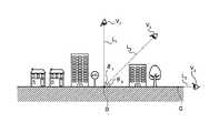
図2は、地図表示装置における俯瞰角度の取り方の一例を示す説明図である。図2において、地表面Gにはビルや居宅、道路標識などの地物が存在している。たとえば、視点位置がV1にある場合、視点位置V1と基準点Dとを結ぶ線分L1と、地表面Gとのなす角度をθ1とする。θ1はおよそ90°である。同様に、視点位置がV2にある場合、視点位置V2と基準点Dとを結ぶ線分L1と、地表面Gとのなす角度はθ2であり、θ2<θ1である。また、視点位置がV3にある場合、視点位置V3と基準点Dとを結ぶ線分L3と、地表面Gとのなす角度は0°に近い角度になる。なお、視点V3は、地表面に近い位置の視点を示しており、たとえば歩行者や車両の運転者の視点と同じ高さである。一般に、視点V1から地表面(基準点)を眺めた地図を平面図、視点V2から地表面(基準点)を眺めた地図を俯瞰図といい、視点V3から基準点を眺めた地図はドライバーズビューとなる。よって、「地表面に対して所定の俯瞰角度から眺めた地図」には、視点V1から視点V3までのいずれかの視点から眺めた地図が含まれる。FIG. 2 is an explanatory diagram illustrating an example of how to obtain an overhead angle in the map display device. In FIG. 2, features such as buildings, homes, and road signs exist on the ground surface G. For example, when the viewpoint position is V1 , the angle formed by the line segment L1 connecting the viewpoint position V1 and the reference point D and the ground surface G is θ1 . θ1 is approximately 90 °. Similarly, when the viewpoint position is V2 , the angle between the line segment L1 connecting the viewpoint position V2 and the reference point D and the ground surface G is θ2 , and θ2 <θ1 . When the viewpoint position is at V3 , the angle formed by the line segment L3 connecting the viewpoint position V3 and the reference point D and the ground surface G is an angle close to 0 °. The viewpoint V3 indicates a viewpoint close to the ground surface, and is, for example, the same height as the viewpoint of a pedestrian or a vehicle driver. In general, a map looking at the ground surface (reference point) from the viewpoint V1 is called a plan view, a map looking at the ground surface (reference point) from the viewpoint V2 is called an overhead view, and a map looking at the reference point from the viewpoint V3 Becomes Driver's View. Therefore, the “map viewed from a predetermined overhead angle with respect to the ground surface” includes a map viewed from any one of the viewpoints V1 to V3 .
図1の説明に戻り、タッチパネル102は、表示部101に重ねて設けられる。タッチパネル102は、地図表示装置100に対する操作入力の受け付けなどに用いられる。具体的には、たとえば、表示部101に操作ボタンなどを表示し、ユーザに所望の操作位置をタッチ(接触)させることによって操作入力を受け付ける。 Returning to the description of FIG. 1, the
判別部103は、タッチパネルに物体が接触する際の接触強度を判別する。物体とは、たとえばユーザの手や指である。判別部103は、物体の接触強度を少なくとも2段階(たとえば、物体の接触強度が所定強度より大きいか、所定強度以下であるか)で判別する。 The
表示制御部104は、判別部103の判別結果に基づいて表示部101に表示する地図の表示態様を制御する。具体的には、表示制御部104は、接触強度が所定の強度以下の場合は地図をスクロールし、接触強度が所定の強度より大きい場合は俯瞰角度を変更する。地図をスクロールする場合、表示制御部104は、たとえば、現在表示している地図データの中心点からタッチパネル102(表示部101)上における物体の接触点に向かう方向に地図データをスクロールする。 The
俯瞰角度を変更する場合、表示制御部104は、地表面が傾斜したときに基準点より奥側の地図を表示するタッチパネル102の領域に物体が接触した場合には、俯瞰角度を小さくする。すなわち、基準点より奥側にタッチされた場合は、表示する地図をドライバーズビューに近づける。一方、表示制御部104は、地表面が傾斜したときに基準点より手前側の地図を表示するタッチパネル102の領域に物体が接触した場合には、俯瞰角度を大きくする。すなわち、基準点より手前側がタッチされた場合は、地図を平面図に近づける。 When changing the bird's-eye view angle, the
また、俯瞰角度を変更する際、表示制御部104は、基準点とタッチパネル102に物体が接触した点との距離が遠いほど俯瞰角度を変更する速度を速くするようにしてもよい。この場合、ユーザは、俯瞰角度を大きく変更したい場合はタッチパネル102上の基準点から遠い点に接触し、多少変更したいのみの場合はタッチパネル102上の基準点から近い点に接触すれば、効率的に俯瞰角度を変更することができる。 When changing the overhead angle, the
また、表示制御部104は、タッチパネル102に対する物体の接触が継続している間、スクロールまたは俯瞰角度の変更を継続するようにしてもよい。この場合、表示制御部104は、地図のスクロールが継続されている間に接触強度が所定の強度より大きくなった場合は、俯瞰角度を変更するのではなく、スクロールする速度を速くするようにしてもよい。また、表示制御部104は、地図のスクロールが継続されている間に接触強度が所定の強度より大きくなっても、接触強度の変化を処理に反映せずに引き続きスクロールを継続してもよい。 Further, the
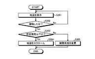
図3は、地図表示装置による地図表示処理の手順を示すフローチャートである。図2のフローチャートにおいて、地図表示装置100は、まず、表示部101に地表面に対して所定の俯瞰角度から眺めた地図を表示する(ステップS301)。このとき表示される地図は、上記の視点V1から視点V3までのいずれかの俯瞰角度から眺めた地図である。つぎに、地図表示装置100は、タッチパネル102に物体が接触したか否かを判断する(ステップS302)。物体が接触しない場合は(ステップS302:No)、ステップS301に戻り、そのまま地図の表示を継続する。FIG. 3 is a flowchart showing the procedure of map display processing by the map display device. In the flowchart of FIG. 2, the map display device 100 first displays a map viewed from a predetermined overhead angle with respect to the ground surface on the display unit 101 (step S301). The map displayed at this time is a map viewed from any overhead angle from the viewpoint V1 to the viewpoint V3 . Next, the map display apparatus 100 determines whether or not an object has touched the touch panel 102 (step S302). If the object does not contact (step S302: No), the process returns to step S301 and the display of the map is continued as it is.
一方、物体が接触した場合(ステップS302:Yes)、地図表示装置100は、判別部103によって物体の接触強度を判別して、接触強度が所定強度以下か否かを判断する(ステップS303)。所定強度以下の場合(ステップS303:Yes)、地図表示装置100は、表示部101に表示している地図をスクロールして(ステップS304)、本フローチャートによる処理を終了する。一方、接触強度が所定強度以下ではない(所定強度より大きい)場合(ステップS303:No)、地図表示装置100は、表示している地図の俯瞰角度を変更して(ステップS305)、本フローチャートによる処理を終了する。 On the other hand, when the object is in contact (step S302: Yes), the map display device 100 determines the contact strength of the object by the
以上説明したように、地図表示装置100は、タッチパネル102に対する物体の接触強度を判別し、接触強度が所定の強度以下の場合は地図をスクロールし、接触強度が所定の強度より大きい場合は地図の俯瞰角度を変更する。これにより、俯瞰図の俯瞰角度を変更するためのインターフェースを設ける必要がなく、表示部101の表示領域やその他の操作デバイスを有効に活用することができる。 As described above, the map display device 100 determines the contact strength of an object with respect to the
また、地図表示装置100は、タッチパネル102への接触強度の強弱のみで2種類の操作入力を受け付けることができる。タッチパネル102への接触強度の強弱を変更することは、他の操作(たとえば2種類のボタンを押し分けるなど)と比較して容易におこなうことができる。このため、地図表示装置100が車両などの移動体に搭載されている場合などであっても、移動に支障をきたすことなく操作をおこなうことができる。 Further, the map display device 100 can accept two types of operation inputs only with the strength of the contact strength with the
また、地図表示装置100は、タッチパネル102に対する物体の接触が継続している間、スクロールまたは俯瞰角度の変更を継続する。これにより、地図の表示領域や俯瞰角度を大きく変更したり、地図の表示領域や俯瞰角度を連続的に変更したりする操作を容易におこなうことができる。また、地図表示装置100は、地図のスクロールが継続されている間に接触強度が所定の強度より大きくなった場合はスクロールする速度を速くする。これは、現在のスクロール速度が遅いと感じている場合、ユーザのタッチパネル102への接触強度が強くなる傾向があるためである。接触強度に基づいてスクロール速度を変更することによって、より直感的にスクロール操作をおこなうことができる。 Further, the map display device 100 continues to scroll or change the overhead angle while the contact of the object with the
また、地図表示装置100は、俯瞰角度を変更する際、基準点より奥側の領域に物体が接触すると俯瞰角度を小さくし、基準点より手前側の領域に物体が接触すると俯瞰角度を大きくする。これにより、俯瞰角度の変更操作を直感的におこなうことができ、ユーザは容易に俯瞰角度を所望の角度に変更することができる。 In addition, when changing the overhead angle, the map display device 100 decreases the overhead angle when an object comes in contact with a region deeper than the reference point, and increases the overhead angle when the object comes in contact with a region closer to the reference point. . Thereby, the overhead angle changing operation can be intuitively performed, and the user can easily change the overhead angle to a desired angle.
また、地図表示装置100は、俯瞰角度を変更する際、基準点とタッチパネルに前記物体が接触した点との距離が遠いほど俯瞰角度を変更する速度を速くする。これにより、俯瞰角度を大きく変更したい場合などに効率的に表示を変更することができる。 Further, when changing the bird's-eye view angle, the map display device 100 increases the speed at which the bird's-eye view angle is changed as the distance between the reference point and the point where the object touches the touch panel is longer. Thereby, a display can be changed efficiently, when changing a bird's-eye view angle largely.
以下に、本発明の実施例について説明する。本実施例では、実施の形態にかかる地図表示装置100を、車両に搭載されたナビゲーション装置400として本発明を適用した場合の一例について説明する。 Examples of the present invention will be described below. In this example, an example in which the present invention is applied to the map display device 100 according to the embodiment as a
(ナビゲーション装置400のハードウェア構成)
図4は、ナビゲーション装置のハードウェア構成を示すブロック図である。実施例にかかるナビゲーション装置400は、CPU401、ROM402、RAM403、各種データを記録/再生する記録再生部404、各種データを記録する記録部405、音声I/F(インターフェース)406、マイク407、スピーカ408、入力デバイス409、映像I/F410、ディスプレイ411、カメラ412、通信I/F413、GPSユニット414を備えている。各構成部401〜414は、バス420によってそれぞれ接続されている。(Hardware configuration of navigation device 400)
FIG. 4 is a block diagram illustrating a hardware configuration of the navigation apparatus. The
CPU401は、ナビゲーション装置400の全体の制御を司る。ROM402は、ブートプログラム、地図データ表示プログラム、経路探索プログラム、施設検索プログラムなどのプログラムを記録している。RAM403は、CPU401のワークエリアとして使用される。すなわち、CPU401は、RAM403をワークエリアとして使用しながら、ROM402に記録された各種プログラムを実行することによって、ナビゲーション装置400の全体の制御を司る。 The
記録再生部404は、CPU401の制御に従って記録部405に対するデータの読み取り/書き込みを制御する。記録部405は、記録再生部404の制御で書き込まれたデータを記録する。記録再生部404としては、たとえば、磁気ディスクドライブや光ディスクドライブ、記録部405としては、たとえば、HD(ハードディスク)、FD(フレキシブルディスク)、フラッシュメモリ、MO、SSD(Solid State Disk)、メモリカードなどを用いることができる。 The recording / reproducing
記録部405に記録される情報の一例としては、たとえば地図データが挙げられる。地図データは、建物、河川、地表面などの地物(フィーチャ)をあらわす背景データと、道路の形状をあらわす道路形状データとを含んでおり、地区ごとに分けられた複数のデータファイルによって構成されている。 An example of information recorded in the
道路形状データは、さらに交通条件データを有する。交通条件データには、たとえば、各ノードについて、信号や横断歩道などの有無、高速道路の出入り口やジャンクションの有無、各リンクについての長さ(距離)、道幅、進行方向、道路種別(高速道路、有料道路、一般道路など)などの情報が含まれている。 The road shape data further includes traffic condition data. The traffic condition data includes, for example, whether or not there is a signal or a pedestrian crossing, whether or not there is a highway doorway or junction, the length (distance) of each link, road width, direction of travel, road type (highway, Such as toll roads and general roads).
機能データは、地図上の施設の形状をあらわす3次元データ、当該施設の説明をあらわす文字データ、その他地図データ以外の各種のデータである。地図データや機能データは、地区ごとあるいは機能ごとにブロック分けされた状態で記録されている。具体的には、たとえば、地図データは、各々が、表示画面に表示された地図において所定の地区をあらわすように、地区ごとにブロック分けすることができる状態で記録されている。また、たとえば、機能データは、各々が、1つの機能を実現するように、機能ごとに複数にブロック分けすることができる状態で記録されている。 The function data is three-dimensional data representing the shape of the facility on the map, character data representing the description of the facility, and other various data other than the map data. Map data and function data are recorded in blocks divided by district or function. Specifically, for example, the map data is recorded in a state where each block can be divided into blocks such that each represents a predetermined district on the map displayed on the display screen. Further, for example, the function data is recorded in a state where each function can be divided into a plurality of blocks so as to realize one function.
また、機能データは、上述した3次元データや文字データに加えて、経路探索、所要時間の算出、経路誘導などを実現するプログラムデータなどの機能を実現するためのデータである。地図データおよび機能データは、それぞれ、地区ごとあるいは機能ごとに分けられた複数のデータファイルによって構成されている。なお、本実施例では地図データが記録部405に記録されているものとするが、通信I/F413などを介して必要な地図データを受信して各種処理に用いるようにしてもよい。 The function data is data for realizing functions such as program data for realizing route search, calculation of required time, route guidance, etc. in addition to the above-described three-dimensional data and character data. Each of the map data and the function data is composed of a plurality of data files divided for each district or each function. In the present embodiment, map data is recorded in the
音声I/F406は、音声入力用のマイク407および音声出力用のスピーカ408に接続される。音声I/F406は、再生が指示された音声データをD/A変換して、スピーカ408から音声として出力させる。なお、スピーカ408は、ナビゲーション装置400から着脱可能であってもよいし、ナビゲーション装置400の本体から離れた場所にあってもよい。マイク407は、たとえば、車両のサンバイザー付近に設置され、ユーザの発話などを集音し、音声I/F406に出力する。マイク407に集音された音声は、音声I/F406内でA/D変換される。 The audio I /
入力デバイス409は、文字、数値、各種指示などの入力のための複数のキーを備えたリモコン、キーボード、およびタッチパネルなどによって構成される。本実施例にかかるナビゲーション装置400は、入力デバイス409として、少なくともディスプレイ411を利用したタッチパネルを備える。後述するように、ナビゲーション装置400のタッチパネルは、ユーザの指などの物体がディスプレイ411の表面に接触したことを検知する他、ディスプレイ411の表面の近傍に物体が接近したことも検知することができる。 The
映像I/F410は、ディスプレイ411およびカメラ412に接続される。映像I/F410は、具体的には、たとえば、ディスプレイ411を制御するグラフィックコントローラと、即時表示可能な画像情報を一時的に記録するVRAM(Video RAM)などのバッファメモリと、グラフィックコントローラから出力される画像データに基づいてディスプレイ411を制御する制御ICなどによって構成される。 The video I /
ディスプレイ411には、地図データやアイコン、カーソル、メニュー、ウィンドウ、あるいは文字や画像などの各種データが表示される。また、ディスプレイ411の表面にはセンサが設けられており、物体の接近および接触を検知することによって入力デバイス409(タッチパネル)として利用される。本実施例では、実施の形態にかかる表示部101およびタッチパネル102(図1参照)を、ディスプレイ411を利用したタッチパネルとして説明する。 The
カメラ412は、ナビゲーション装置400が搭載された車両の内部あるいは外部の映像を撮影する。カメラ412で撮影する映像は静止画あるいは動画のどちらでもよい。カメラ412によって撮影された映像は、映像I/F410を介して記録部405などに記録される。 The
通信I/F413は、無線を介してネットワークに接続され、ネットワークを介したデータの送受信を可能とする。通信I/F413を用いることにより、ナビゲーション装置400は、ネットワークを介して地図データ(地図データの更新データなどを含む)を取得することも可能となる。すなわち、記録部305に地図データが記録されていなくても、ディスプレイ311の表示に必要な地図データを外部のサーバから取得することが可能である。通信網には、たとえばLAN、WAN、公衆回線網や携帯電話網などがある。 The communication I /
GPSユニット414は、GPS衛星からの電波を受信し、ナビゲーション装置400が搭載された車両の現在地点を示す情報を出力する。また、GPSユニット414は、速度センサ、加速度センサ、角速度センサなどの各種センサを備える。GPSユニット414の出力情報は、CPU401によるナビゲーション装置400の現在地点の算出に際して利用される。現在地点を示す情報は、たとえば緯度・経度、高度などの、地図データ上の1点を特定する情報である。 The
図1に示した地図表示装置100の各構成部は、図4におけるROM402、RAM403、記録部405などに記録されたプログラムやデータを用いて、CPU401が所定のプログラムを実行し、各部を制御することによってその機能を実現する。 Each component of the map display device 100 shown in FIG. 1 uses the programs and data recorded in the
(ナビゲーション装置400による地図表示処理)
つぎに、ナビゲーション装置400による地図表示処理について説明する。ナビゲーション装置400は、経路誘導をおこなう際、車両の現在位置周辺の地図データをディスプレイ411に表示する。また、ナビゲーション装置400は、ユーザから指定された任意の地点周辺の地図データを記録部405から読み出してディスプレイ411に表示することも可能である。(Map display processing by the navigation device 400)
Next, map display processing by the
ナビゲーション装置400における地図データの表示態様には様々な種類があるが、その一例として、地表面を所定の俯瞰角度から眺めた地図が挙げられる。地図は、俯瞰角度を変更することによって、地表面を真上から見た平面図に近いもの(俯瞰角度90°)から、地表面上から地表面上の他の点を見たドライバーズビューに近いもの(俯瞰角度0°に近い角度)まで、表示態様を変更することが可能である。 There are various types of display modes of the map data in the
ユーザから俯瞰角度の変更を受け付けるインターフェースは各種の形態が考えられる。しかし、走行中のナビゲーション装置400のディスプレイ411には、経路案内情報や目的地点までの距離、地図の縮尺変更ボタンなど各種の情報が表示されている。このため、俯瞰角度の変更を受け付けるインターフェースを常時ディスプレイ411に表示していると、地図データの表示領域が狭くなるなど、ユーザが必要とする情報が即座に得られなくなってしまう可能性がある。 There are various types of interfaces that accept a change in the overhead angle from the user. However, various information such as route guidance information, a distance to the destination, and a map scale change button are displayed on the
このため、本実施例にかかるナビゲーション装置400では、物体の接触強度を検知することができる感圧検知型のタッチパネルを用いて、ディスプレイ411に対するユーザの手の接触強度を検知する。そして、ナビゲーション装置400は、地図を表示中のディスプレイ411に対して接触があった場合、接触強度が所定強度以下の場合は表示中の地図をスクロールするための操作入力として処理する。一方、接触強度が所定強度より大きい場合には地図の俯瞰角度を変更するための操作入力として処理する。これにより、俯瞰角度の変更を受け付けるインターフェースを常時表示しなくても、容易に俯瞰角度を変更するための操作入力を受け付けることができる。なお、接触強度が所定強度以下の場合に、地図をスクロールする操作入力とするのは、地図を表示しているディスプレイ411への接触は、表示中の地図をスクロールするための操作入力として扱うのが一般的なためである。 For this reason, in the
図5および図6は、感圧検知型のタッチパネルの概要を示す説明図である。図5は、感圧検知型のタッチパネル500を横方向から見た図であり、図5は、タッチパネル500を正面から見た図である。図5に示すように、タッチパネル500は、ディスプレイ411の表面に、物体の接触強度を検出するタッチセンサ501を備えている。タッチセンサ501は、少なくとも2段階(所定強度以下か、所定強度より大きいか)で物体の接触強度を検出することができる。 5 and 6 are explanatory diagrams showing an outline of a pressure-sensitive detection type touch panel. FIG. 5 is a view of the pressure-sensitive detection
また、図6に示すように、タッチセンサ501は、ユーザの指Fが接触したタッチパネル500上の位置を検出する。ユーザの指Fが接触した位置を検出する場合、タッチセンサ501は、たとえばタッチパネル500の横方向にX座標、縦方向にY座標を取り、ユーザの指Fが接触した位置Pを座標(X,Y)のように検出する。 In addition, as illustrated in FIG. 6, the
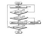
つぎに、ナビゲーション装置400による地図表示処理の手順について説明する。図7は、ナビゲーション装置による地図表示処理の手順を示すフローチャートである。図7のフローチャートにおいて、ナビゲーション装置400は、ディスプレイ411に所定地点を基準点とした地図を表示する(ステップS701)。所定地点とは、たとえば、車両の現在位置やユーザから指定された地点である。基準点は表示する地図の中心としてもよいし、その他の位置(たとえば、ディスプレイ411の中心よりもやや下側)としてもよい。また、ステップS701で表示する俯瞰図の俯瞰角度は、デフォルトで指定されている角度やユーザから指定された角度、前回地図を表示した際に指定された角度などにする。 Next, the procedure of map display processing by the
つぎに、ナビゲーション装置400は、ディスプレイ411に物体(ユーザの手など)の接触があったか否かを判断する(ステップS702)。物体の接触があるまでは(ステップS702:No)、ステップS701に戻り、地図の表示を継続する。一方、物体の接触があった場合は(ステップS702:Yes)、接触強度が所定強度以下であるか否かを判断する(ステップS703)。物体の接触強度は、図5および図6で説明したタッチセンサによる検知結果などを用いて判断する。 Next, the
接触強度が所定強度以下の場合(ステップS703:Yes)、ナビゲーション装置400は、接触された方向に地図をスクロールする(ステップS704)。接触された方向とは、たとえば地図データの基準点からディスプレイ411上の接触された点に向かう方向である。 If the contact strength is less than or equal to the predetermined strength (step S703: Yes), the
一方、接触強度が所定強度より大きい場合(ステップS703:No)、ナビゲーション装置400は、表示している俯瞰図の俯瞰角度を変更する(ステップS705)。このとき、たとえば、物体が接触した位置が基準点より奥側の地図を表示する領域である場合は俯瞰角度を小さくする。一方、物体が接触した位置が基準点より手前側の地図を表示する領域である場合は俯瞰角度を大きくする。なお、俯瞰角度が小さくなると、ディスプレイ411に表示される俯瞰図は、基準点を地表面上の他の点(視点位置)から見た図(ドライバーズビュー)に近づく。また、俯瞰角度が大きくなると、ディスプレイ411に表示される俯瞰図は、基準点を真上から見た図(平面図)に近づく。 On the other hand, when the contact strength is higher than the predetermined strength (step S703: No), the
ディスプレイ411の表示が俯瞰図以外の表示に変更されるまで(ステップS706:No)、ナビゲーション装置400は、ステップS701に戻り、以降の処理を継続する。そして、ディスプレイ411の表示が俯瞰図以外の表示に変更されると(ステップS706:Yes)、本フローチャートによる処理を終了する。 Until the display on the
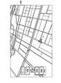
図8〜図12は、ディスプレイに表示される地図の一例を示す説明図である。図8には、所定の俯瞰角度で地表面上の基準点Dを見た俯瞰図800が示されている、基準点Dは、車両の現在位置であり、車両の現在位置を示すアイコンが表示されている。俯瞰図800の俯瞰角度を変更したい場合、ユーザはディスプレイ411の表面を強く(所定強度よりも大きい強度で)押下すればよい。このとき、基準点Dよりも奥側の領域A1を押下した場合は、俯瞰角度が小さくなり、ディスプレイ411に表示される俯瞰図は、図9の俯瞰図900のようになる。図9の俯瞰図900は、図8の俯瞰図800と比較して視点が地表面に近づいている。一方、図8において、基準点Dよりも手前側の領域A2を押下した場合は、俯瞰角度が大きくなり、ディスプレイ411に表示される俯瞰図は、図10の俯瞰図1000のようになる。図10の俯瞰図1000は、図8の俯瞰図800と比較して視点が地表面から離れ、より上空から見下ろした図になっている。 8-12 is explanatory drawing which shows an example of the map displayed on a display. FIG. 8 shows an
なお、上記の例では、車両の現在位置を基準点Dとしているが、基準点Dの位置はこれに限らない。たとえば、ディスプレイの表示画面の中央を基準点Dとしてもよいし、後述する図11、図12におけるアイコン(十字アイコン)を基準点Dとしてもよい。また、ナビゲーション装置400は、斜め上方から眺めた俯瞰図を表示する際に、地表面を示す領域の中央に基準点Dを設けてもよい。この場合、俯瞰角度を変更するたびに画面全体における地表面を示す領域の割合が変化する(俯瞰角度が小さいほど空を示す領域が増大し、地表面を示す領域が減少する)ので、これに伴い基準点Dの位置も変化する。さらに、この場合、ナビゲーション装置400は、空を示す領域を強く押圧しても俯瞰角度を変更しないようにしてもよい。このようにすることで、ユーザは、地表面を押下するとその面が傾くという感覚がより明確になり、俯瞰角度を変更する操作が直感的に行える。 In the above example, the current position of the vehicle is the reference point D, but the position of the reference point D is not limited to this. For example, the center of the display screen of the display may be set as the reference point D, and an icon (cross icon) in FIGS. Further, the
なお、俯瞰角度には最小値および最大値があり、俯瞰角度が最小値(たとえば0°に近い角度)のときに基準点Dよりも奥側の領域A1を強く押下しても、それ以上俯瞰角度を小さくすることができないため、操作は無効とされる。同様に、俯瞰角度が最大値(たとえば90°)のときに基準点Dよりも手前側の領域A2を強く押下しても、それ以上俯瞰角度を大きくすることができないため、操作は無効とされる。 Note that the bird's-eye view angle has a minimum value and a maximum value, and even when the bird's-eye view angle is the minimum value (for example, an angle close to 0 °), even if the area A1 on the back side from the reference point D is pressed strongly, the bird's-eye view angle further increases. Since the angle cannot be reduced, the operation is invalidated. Similarly, even if the area A2 closer to the front side than the reference point D is strongly pressed when the overhead angle is the maximum value (for example, 90 °), the overhead angle cannot be increased any more, so the operation is invalidated. The
また、図8において、俯瞰図800の表示範囲を変更(スクロール)したい場合、ユーザはディスプレイ411の表面を弱めに(所定強度以下で)押下すればよい。このとき、基準点Dよりも奥側の領域A1を押下した場合は、図11の俯瞰図1100に示すように、基準点Dよりも奥側の領域の地図へと表示がスクロールする。図11では、基準点Dが車両の現在位置ではなくなり、基準点を示すアイコンが表示されている。一方、図8において、基準点Dよりも手前側の領域A2を押下した場合は、図12の俯瞰図1200に示すように、基準点Dよりも手前側の領域の地図へと表示がスクロールする。図12においても、基準点Dは車両の現在位置ではなくなり、車両の現在位置を示すアイコンから離れた位置に基準点を示すアイコンが表示されている。 In addition, in FIG. 8, when the display range of the
また、ユーザが、ディスプレイ411に対する接触を継続しておこなった場合、すなわち、ディスプレイ411を長押しした場合、ナビゲーション装置400は、接触強度に基づく処理(俯瞰角度の変更またはスクロール)を継続しておこなう。たとえば、図8において俯瞰図800の領域A1が強く長押しされた場合は、押下が中止されるか、俯瞰角度が最小値になるまで、俯瞰角度を徐々に小さくするようにディスプレイ411の表示を変化させる。また、図8において俯瞰図800の領域A1が弱く長押しされた場合は、押下が中止されるまで、基準位置Dより手前側の方向に地図をスクロールさせ続ける。 In addition, when the user continues to touch the
このようにディスプレイ411が長押しされている間に、接触強度が変化した場合であっても、ナビゲーション装置400は開始した処理を継続しておこなう。たとえば、ディスプレイ411が弱く長押しされている間(すなわち、スクロールをおこなっている間)に、接触強度が変化して所定強度より大きくなった場合であっても、ナビゲーション装置400は、地図のスクロールを継続する。また、このようにスクロール中に接触強度が強くなった場合、ナビゲーション装置400は、地図のスクロール速度を速めるようにしてもよい。これは、現在のスクロール速度が遅いと感じている場合、ユーザのディスプレイ411への接触強度が強くなる傾向があるためである。接触強度に基づいてスクロール速度を変更することによって、より直感的にスクロール操作をおこなうことができる。 Thus, even if the contact strength changes while the
また、ディスプレイ411上の接触された点と地図の基準点との距離に応じて、俯瞰角度の変更速度またはスクロール速度を変更してもよい。たとえば、ディスプレイ411上の接触された点と地図の基準点と距離が長いほど、俯瞰角度の変更速度またはスクロール速度を早めるようにする。これにより、俯瞰角度を大きく変更したい場合や現在表示している領域から離れた地点の地図を見たい場合に、効率的に表示を変更することができる。 Further, the overhead angle changing speed or the scrolling speed may be changed according to the distance between the point touched on the
以上説明したように、ナビゲーション装置400は、ディスプレイ411に対する物体の接触強度を判別し、接触強度が所定の強度以下の場合は地図をスクロールし、接触強度が所定の強度より大きい場合は地図の俯瞰角度を変更する。これにより、俯瞰図の俯瞰角度を変更するためのインターフェースを設ける必要がなく、ディスプレイ411の表示領域やその他の操作デバイスを有効に活用することができる。 As described above, the
また、ナビゲーション装置400は、ディスプレイ411への接触強度の強弱のみで2種類の操作入力を受け付けることができる。ディスプレイ411への接触強度の強弱を変更することは、他の操作(たとえば2種類のボタンを押し分けるなど)と比較して容易におこなうことができる。このため、ナビゲーション装置400のように車両などの移動体に搭載されている機器においても、移動に支障をきたすことなく操作をおこなうことができる。 Further, the
また、ナビゲーション装置400は、ディスプレイ411に対する物体の接触が継続している間、スクロールまたは俯瞰角度の変更を継続する。これにより、地図の表示領域や俯瞰角度を大きく変更したり、地図の表示領域や俯瞰角度を連続的に変更したりする操作を容易におこなうことができる。また、ナビゲーション装置400は、地図のスクロールが継続されている間に接触強度が所定の強度より大きくなった場合はスクロールする速度を速くする。これは、現在のスクロール速度が遅いと感じている場合、ユーザのディスプレイ411への接触強度が強くなる傾向があるためである。接触強度に基づいてスクロール速度を変更することによって、より直感的にスクロール操作をおこなうことができる。 In addition, the
また、ナビゲーション装置400は、俯瞰角度を変更する際、基準点より奥側の領域に物体が接触すると俯瞰角度を小さくし、基準点より手前側の領域に物体が接触すると俯瞰角度を大きくする。これにより、俯瞰角度の変更操作を直感的におこなうことができ、ユーザは容易に俯瞰角度を所望の角度に変更することができる。 In addition, when changing the overhead angle, the
また、ナビゲーション装置400は、俯瞰角度を変更する際、基準点とタッチパネルに前記物体が接触した点との距離が遠いほど俯瞰角度を変更する速度を速くする。これにより、俯瞰角度を大きく変更したい場合などに効率的に表示を変更することができる。 In addition, when changing the overhead angle, the
なお、本実施の形態で説明した地図表示方法は、あらかじめ用意されたプログラムをパーソナル・コンピュータやワークステーションなどのコンピュータで実行することにより実現することができる。このプログラムは、ハードディスク、フレキシブルディスク、CD−ROM、MO、DVDなどのコンピュータで読み取り可能な記録媒体に記録され、コンピュータによって記録媒体から読み出されることによって実行される。またこのプログラムは、インターネットなどのネットワークを介して配布することが可能な伝送媒体であってもよい。 The map display method described in this embodiment can be realized by executing a program prepared in advance on a computer such as a personal computer or a workstation. This program is recorded on a computer-readable recording medium such as a hard disk, a flexible disk, a CD-ROM, an MO, and a DVD, and is executed by being read from the recording medium by the computer. The program may be a transmission medium that can be distributed via a network such as the Internet.
100 地図表示装置
101 表示部
102 タッチパネル
103 判別部
104 表示制御部DESCRIPTION OF SYMBOLS 100 Map display apparatus 101
Claims (8)
Translated fromJapanese前記表示手段に重ねて設けられるタッチパネルと、
前記タッチパネルに物体が接触する際の接触強度を判別する判別手段と、
前記判別手段の判別結果に基づいて前記表示手段に表示する前記地図の表示態様を制御する表示制御手段と、を備え、
前記表示制御手段は、前記接触強度が所定の強度以下の場合は前記地図をスクロールし、前記接触強度が所定の強度より大きい場合は前記俯瞰角度を変更することを特徴とする地図表示装置。Display means capable of displaying a map viewed from a predetermined overhead angle with respect to the ground surface;
A touch panel provided over the display means;
Discriminating means for discriminating contact strength when an object contacts the touch panel;
Display control means for controlling the display mode of the map displayed on the display means based on the determination result of the determination means,
The map display device characterized in that the display control means scrolls the map when the contact strength is equal to or lower than a predetermined strength, and changes the overhead angle when the contact strength is higher than a predetermined strength.
前記表示制御手段は、前記俯瞰角度を変更する際、前記地表面が傾斜したときに前記基準点より奥側の地図を表示する前記タッチパネルの領域に前記物体が接触すると前記俯瞰角度を小さくし、前記地表面が傾斜したときに前記基準点より手前側の地図を表示する前記タッチパネルの領域に前記物体が接触すると前記俯瞰角度を大きくすることを特徴とする請求項1〜3のいずれか一つに記載の地図表示装置。The display means displays the map in which the ground surface is inclined with a reference point on the display means as a center when displaying an overhead view of the map when the ground surface is viewed obliquely from above.
When changing the overhead angle, the display control means reduces the overhead angle when the object comes into contact with the area of the touch panel that displays a map behind the reference point when the ground surface is inclined, The bird's-eye view angle is increased when the object comes into contact with the area of the touch panel that displays a map in front of the reference point when the ground surface is inclined. The map display device described in 1.
前記表示手段に地表面に対して所定の俯瞰角度から眺めた地図を表示する表示工程と、
前記タッチパネルに物体が接触する際の接触強度を判別する判別工程と、
前記判別工程の判別結果に基づいて前記表示手段に表示する前記地図の表示態様を制御する表示制御工程と、を含み、
前記表示制御工程では、前記接触強度が所定の強度以下の場合は前記地図をスクロールし、前記接触強度が所定の強度より大きい場合は前記俯瞰角度を変更することを特徴とする地図表示方法。A map display method in a map display device comprising: a display means; and a touch panel provided on the display means.
A display step of displaying a map viewed from a predetermined overhead angle with respect to the ground surface on the display means;
A discriminating step for discriminating contact strength when an object contacts the touch panel;
A display control step for controlling the display mode of the map displayed on the display means based on the determination result of the determination step,
The map display method characterized in that, in the display control step, the map is scrolled when the contact strength is equal to or lower than a predetermined strength, and the overhead angle is changed when the contact strength is higher than the predetermined strength.
Applications Claiming Priority (1)
| Application Number | Priority Date | Filing Date | Title |
|---|---|---|---|
| PCT/JP2009/070139WO2011064895A1 (en) | 2009-11-30 | 2009-11-30 | Map display device, map display method, map display program, and recording medium |
Publications (2)
| Publication Number | Publication Date |
|---|---|
| JP4943543B2true JP4943543B2 (en) | 2012-05-30 |
| JPWO2011064895A1 JPWO2011064895A1 (en) | 2013-04-11 |
Family
ID=44066014
Family Applications (1)
| Application Number | Title | Priority Date | Filing Date |
|---|---|---|---|
| JP2010534307AExpired - Fee RelatedJP4943543B2 (en) | 2009-11-30 | 2009-11-30 | MAP DISPLAY DEVICE, MAP DISPLAY METHOD, MAP DISPLAY PROGRAM, AND RECORDING MEDIUM |
Country Status (3)
| Country | Link |
|---|---|
| US (1) | US8922592B2 (en) |
| JP (1) | JP4943543B2 (en) |
| WO (1) | WO2011064895A1 (en) |
Families Citing this family (29)
| Publication number | Priority date | Publication date | Assignee | Title |
|---|---|---|---|---|
| JP5767525B2 (en)* | 2011-08-08 | 2015-08-19 | 東芝アルパイン・オートモティブテクノロジー株式会社 | Input device |
| EP2763010A4 (en)* | 2011-09-26 | 2015-06-03 | Nec Casio Mobile Comm Ltd | Mobile information processing terminal |
| WO2013046426A1 (en)* | 2011-09-30 | 2013-04-04 | パイオニア株式会社 | Head-up display, image display method, image display program, and display device |
| US10191641B2 (en) | 2011-12-29 | 2019-01-29 | Apple Inc. | Device, method, and graphical user interface for navigation of information in a map-based interface |
| JP5780193B2 (en)* | 2012-03-29 | 2015-09-16 | アイシン・エィ・ダブリュ株式会社 | Image display apparatus, image display method, and computer program |
| US9367959B2 (en) | 2012-06-05 | 2016-06-14 | Apple Inc. | Mapping application with 3D presentation |
| US8880336B2 (en) | 2012-06-05 | 2014-11-04 | Apple Inc. | 3D navigation |
| US8965696B2 (en) | 2012-06-05 | 2015-02-24 | Apple Inc. | Providing navigation instructions while operating navigation application in background |
| US9311750B2 (en) | 2012-06-05 | 2016-04-12 | Apple Inc. | Rotation operations in a mapping application |
| US9159153B2 (en) | 2012-06-05 | 2015-10-13 | Apple Inc. | Method, system and apparatus for providing visual feedback of a map view change |
| US9997069B2 (en) | 2012-06-05 | 2018-06-12 | Apple Inc. | Context-aware voice guidance |
| US9886794B2 (en) | 2012-06-05 | 2018-02-06 | Apple Inc. | Problem reporting in maps |
| US10176633B2 (en) | 2012-06-05 | 2019-01-08 | Apple Inc. | Integrated mapping and navigation application |
| US9418672B2 (en) | 2012-06-05 | 2016-08-16 | Apple Inc. | Navigation application with adaptive instruction text |
| US9482296B2 (en) | 2012-06-05 | 2016-11-01 | Apple Inc. | Rendering road signs during navigation |
| US9269178B2 (en) | 2012-06-05 | 2016-02-23 | Apple Inc. | Virtual camera for 3D maps |
| US8983778B2 (en) | 2012-06-05 | 2015-03-17 | Apple Inc. | Generation of intersection information by a mapping service |
| US9135751B2 (en) | 2012-06-05 | 2015-09-15 | Apple Inc. | Displaying location preview |
| US9541417B2 (en) | 2012-06-05 | 2017-01-10 | Apple Inc. | Panning for three-dimensional maps |
| US9230556B2 (en) | 2012-06-05 | 2016-01-05 | Apple Inc. | Voice instructions during navigation |
| CN104823218A (en)* | 2012-12-03 | 2015-08-05 | 哈曼国际工业有限公司 | System and method for detecting pedestrians using a single normal camera |
| JP5821895B2 (en)* | 2013-05-22 | 2015-11-24 | トヨタ自動車株式会社 | Map display controller |
| US9418485B2 (en) | 2013-05-31 | 2016-08-16 | Apple Inc. | Adjusting heights for road path indicators |
| US9678651B2 (en) | 2013-06-08 | 2017-06-13 | Apple Inc. | Mapping application with interactive compass |
| JP6347934B2 (en) | 2013-10-11 | 2018-06-27 | 株式会社デンソーテン | Image display device, image display system, image display method, and program |
| US9903735B2 (en) | 2015-03-30 | 2018-02-27 | International Business Machines Corporation | Route stabilization scrolling mode |
| US10740972B2 (en)* | 2017-04-28 | 2020-08-11 | Harman International Industries, Incorporated | System and method for presentation and control of augmented vehicle surround views |
| JP6730972B2 (en)* | 2017-10-20 | 2020-07-29 | ヤフー株式会社 | Information control program, information control method, and terminal device |
| JP2019032886A (en)* | 2018-10-24 | 2019-02-28 | パイオニア株式会社 | Display control device, display control method, and display control device program |
Citations (8)
| Publication number | Priority date | Publication date | Assignee | Title |
|---|---|---|---|---|
| JPH06282378A (en)* | 1993-03-30 | 1994-10-07 | Toshiba Corp | Display monitoring device |
| JP2006330428A (en)* | 2005-05-27 | 2006-12-07 | Xanavi Informatics Corp | Map display apparatus |
| JP2007034101A (en)* | 2005-07-29 | 2007-02-08 | Matsushita Electric Ind Co Ltd | Data processing device |
| JP2007094708A (en)* | 2005-09-28 | 2007-04-12 | Kddi Corp | Information terminal equipment |
| JP2007192881A (en)* | 2006-01-17 | 2007-08-02 | Xanavi Informatics Corp | On-vehicle map display apparatus |
| JP2007328570A (en)* | 2006-06-08 | 2007-12-20 | Xanavi Informatics Corp | Map display device |
| JP2009140368A (en)* | 2007-12-07 | 2009-06-25 | Sony Corp | Input device, display device, input method, display method, and program |
| JP2009157908A (en)* | 2007-12-07 | 2009-07-16 | Sony Corp | Information display terminal, information display method, and program |
Family Cites Families (7)
| Publication number | Priority date | Publication date | Assignee | Title |
|---|---|---|---|---|
| US4790028A (en)* | 1986-09-12 | 1988-12-06 | Westinghouse Electric Corp. | Method and apparatus for generating variably scaled displays |
| US6654014B2 (en)* | 1995-04-20 | 2003-11-25 | Yoshinori Endo | Bird's-eye view forming method, map display apparatus and navigation system |
| US8479122B2 (en)* | 2004-07-30 | 2013-07-02 | Apple Inc. | Gestures for touch sensitive input devices |
| US9513765B2 (en) | 2007-12-07 | 2016-12-06 | Sony Corporation | Three-dimensional sliding object arrangement method and system |
| JP4605214B2 (en)* | 2007-12-19 | 2011-01-05 | ソニー株式会社 | Information processing apparatus, information processing method, and program |
| US20100309228A1 (en)* | 2009-06-04 | 2010-12-09 | Camilo Mattos | Displaying Multi-Dimensional Data Using a Rotatable Object |
| US8363020B2 (en)* | 2009-08-27 | 2013-01-29 | Symbol Technologies, Inc. | Methods and apparatus for pressure-based manipulation of content on a touch screen |
- 2009
- 2009-11-30WOPCT/JP2009/070139patent/WO2011064895A1/enactiveApplication Filing
- 2009-11-30USUS13/063,879patent/US8922592B2/enactiveActive
- 2009-11-30JPJP2010534307Apatent/JP4943543B2/ennot_activeExpired - Fee Related
Patent Citations (8)
| Publication number | Priority date | Publication date | Assignee | Title |
|---|---|---|---|---|
| JPH06282378A (en)* | 1993-03-30 | 1994-10-07 | Toshiba Corp | Display monitoring device |
| JP2006330428A (en)* | 2005-05-27 | 2006-12-07 | Xanavi Informatics Corp | Map display apparatus |
| JP2007034101A (en)* | 2005-07-29 | 2007-02-08 | Matsushita Electric Ind Co Ltd | Data processing device |
| JP2007094708A (en)* | 2005-09-28 | 2007-04-12 | Kddi Corp | Information terminal equipment |
| JP2007192881A (en)* | 2006-01-17 | 2007-08-02 | Xanavi Informatics Corp | On-vehicle map display apparatus |
| JP2007328570A (en)* | 2006-06-08 | 2007-12-20 | Xanavi Informatics Corp | Map display device |
| JP2009140368A (en)* | 2007-12-07 | 2009-06-25 | Sony Corp | Input device, display device, input method, display method, and program |
| JP2009157908A (en)* | 2007-12-07 | 2009-07-16 | Sony Corp | Information display terminal, information display method, and program |
Also Published As
| Publication number | Publication date |
|---|---|
| US20110249030A1 (en) | 2011-10-13 |
| WO2011064895A1 (en) | 2011-06-03 |
| US8922592B2 (en) | 2014-12-30 |
| JPWO2011064895A1 (en) | 2013-04-11 |
Similar Documents
| Publication | Publication Date | Title |
|---|---|---|
| JP4943543B2 (en) | MAP DISPLAY DEVICE, MAP DISPLAY METHOD, MAP DISPLAY PROGRAM, AND RECORDING MEDIUM | |
| JP5174704B2 (en) | Image processing apparatus and image processing method | |
| JP5349493B2 (en) | Display input device and in-vehicle information device | |
| CN102224479B (en) | Input device, vehicle peripheral monitoring device, icon switch selection method and program | |
| JP4111885B2 (en) | Map search and display method and apparatus | |
| JP6429886B2 (en) | Touch control system and touch control method | |
| CN102239068A (en) | Display input device | |
| JP5754410B2 (en) | Display device | |
| JP4067374B2 (en) | Image processing device | |
| CN111126995A (en) | A payment method and electronic device | |
| JP5358215B2 (en) | Map display device | |
| JP7683970B2 (en) | DISPLAY CONTROL DEVICE, DISPLAY CONTROL METHOD, AND DISPLAY CONTROL PROGRAM | |
| KR20150005386A (en) | A mobile terminal comprising a touch screen supporting a multi touch and method for controlling the mobile terminal | |
| JP5453069B2 (en) | MAP DISPLAY DEVICE, MAP DISPLAY METHOD, MAP DISPLAY PROGRAM, AND RECORDING MEDIUM | |
| JP2019096026A (en) | Operation reception system and operation reception program | |
| JP5389624B2 (en) | Information processing apparatus, input control method, input control program, and recording medium | |
| JP2014170337A (en) | Information display control device, information display device, and information display control method | |
| JP2011117742A (en) | Information processing apparatus, input method, input program, and recording medium | |
| JP5665838B2 (en) | Image processing apparatus, image display method, and program | |
| JP5453070B2 (en) | MAP DISPLAY DEVICE, MAP DISPLAY METHOD, MAP DISPLAY PROGRAM, AND RECORDING MEDIUM | |
| WO2015151154A1 (en) | Display apparatus, display method, and display program | |
| JP2019036325A (en) | Display device, method for display, and display program | |
| JP5472021B2 (en) | Map display device | |
| JP2011196702A (en) | Navigation device including touch panel and map image display method thereof | |
| JP2017182260A (en) | Display processing apparatus and display processing program |
Legal Events
| Date | Code | Title | Description |
|---|---|---|---|
| TRDD | Decision of grant or rejection written | ||
| A01 | Written decision to grant a patent or to grant a registration (utility model) | Free format text:JAPANESE INTERMEDIATE CODE: A01 Effective date:20120214 | |
| A01 | Written decision to grant a patent or to grant a registration (utility model) | Free format text:JAPANESE INTERMEDIATE CODE: A01 | |
| A61 | First payment of annual fees (during grant procedure) | Free format text:JAPANESE INTERMEDIATE CODE: A61 Effective date:20120229 | |
| R150 | Certificate of patent or registration of utility model | Ref document number:4943543 Country of ref document:JP Free format text:JAPANESE INTERMEDIATE CODE: R150 Free format text:JAPANESE INTERMEDIATE CODE: R150 | |
| FPAY | Renewal fee payment (event date is renewal date of database) | Free format text:PAYMENT UNTIL: 20150309 Year of fee payment:3 | |
| LAPS | Cancellation because of no payment of annual fees |