JP4942891B2 - Shaving cartridges and containers for other items - Google Patents
Shaving cartridges and containers for other itemsDownload PDFInfo
- Publication number
- JP4942891B2 JP4942891B2JP2001514214AJP2001514214AJP4942891B2JP 4942891 B2JP4942891 B2JP 4942891B2JP 2001514214 AJP2001514214 AJP 2001514214AJP 2001514214 AJP2001514214 AJP 2001514214AJP 4942891 B2JP4942891 B2JP 4942891B2
- Authority
- JP
- Japan
- Prior art keywords
- container
- cartridge
- synthetic resin
- film
- storage area
- Prior art date
- Legal status (The legal status is an assumption and is not a legal conclusion. Google has not performed a legal analysis and makes no representation as to the accuracy of the status listed.)
- Expired - Lifetime
Links
- 229920003002synthetic resinPolymers0.000claimsdescription90
- 239000000057synthetic resinSubstances0.000claimsdescription90
- 238000007789sealingMethods0.000claimsdescription74
- 238000003860storageMethods0.000claimsdescription52
- 238000000034methodMethods0.000claimsdescription25
- 210000003811fingerAnatomy0.000claimsdescription16
- 239000002184metalSubstances0.000claimsdescription14
- 230000014759maintenance of locationEffects0.000claimsdescription12
- 238000004806packaging method and processMethods0.000claimsdescription12
- 230000004888barrier functionEffects0.000claimsdescription9
- 210000003813thumbAnatomy0.000claimsdescription6
- 238000004519manufacturing processMethods0.000claimsdescription5
- 238000005520cutting processMethods0.000claimsdescription4
- 238000007639printingMethods0.000claimsdescription4
- 238000000465mouldingMethods0.000claimsdescription3
- 230000000977initiatory effectEffects0.000claims3
- 241001391944Commicarpus scandensSpecies0.000claims1
- 230000000149penetrating effectEffects0.000claims1
- 239000002985plastic filmSubstances0.000claims1
- 229920006255plastic filmPolymers0.000claims1
- 229920000098polyolefinPolymers0.000claims1
- 238000000926separation methodMethods0.000claims1
- 239000010408filmSubstances0.000description40
- 239000010410layerSubstances0.000description36
- 229920001903high density polyethylenePolymers0.000description24
- 239000004700high-density polyethyleneSubstances0.000description24
- 229920001684low density polyethylenePolymers0.000description17
- 239000004702low-density polyethyleneSubstances0.000description16
- 229920000139polyethylene terephthalatePolymers0.000description16
- 239000005020polyethylene terephthalateSubstances0.000description16
- -1polypropylenePolymers0.000description16
- 239000011888foilSubstances0.000description14
- 239000000463materialSubstances0.000description10
- 235000013305foodNutrition0.000description5
- 239000012790adhesive layerSubstances0.000description4
- XLYOFNOQVPJJNP-UHFFFAOYSA-NwaterSubstancesOXLYOFNOQVPJJNP-UHFFFAOYSA-N0.000description4
- 239000004743PolypropyleneSubstances0.000description3
- 239000004793PolystyreneSubstances0.000description3
- 239000003599detergentSubstances0.000description3
- 239000005038ethylene vinyl acetateSubstances0.000description3
- 239000002991molded plasticSubstances0.000description3
- 229920000728polyesterPolymers0.000description3
- 229920001155polypropylenePolymers0.000description3
- 229920002223polystyrenePolymers0.000description3
- 238000003466weldingMethods0.000description3
- 239000004278EU approved seasoningSubstances0.000description2
- 239000004698PolyethyleneSubstances0.000description2
- DQXBYHZEEUGOBF-UHFFFAOYSA-Nbut-3-enoic acid;etheneChemical compoundC=C.OC(=O)CC=CDQXBYHZEEUGOBF-UHFFFAOYSA-N0.000description2
- 239000013039cover filmSubstances0.000description2
- 235000011194food seasoning agentNutrition0.000description2
- 229920005669high impact polystyrenePolymers0.000description2
- 239000004797high-impact polystyreneSubstances0.000description2
- 238000005304joiningMethods0.000description2
- 230000002093peripheral effectEffects0.000description2
- 230000035699permeabilityEffects0.000description2
- 229920003023plasticPolymers0.000description2
- 239000004033plasticSubstances0.000description2
- 229920001200poly(ethylene-vinyl acetate)Polymers0.000description2
- 229920002285poly(styrene-co-acrylonitrile)Polymers0.000description2
- 229920000573polyethylenePolymers0.000description2
- 235000011888snacksNutrition0.000description2
- JOYRKODLDBILNP-UHFFFAOYSA-NEthyl urethaneChemical compoundCCOC(N)=OJOYRKODLDBILNP-UHFFFAOYSA-N0.000description1
- 241001272720Medialuna californiensisSpecies0.000description1
- 239000004677NylonSubstances0.000description1
- 239000004820Pressure-sensitive adhesiveSubstances0.000description1
- 230000002745absorbentEffects0.000description1
- 239000002250absorbentSubstances0.000description1
- 239000004676acrylonitrile butadiene styreneSubstances0.000description1
- 239000000853adhesiveSubstances0.000description1
- 230000001070adhesive effectEffects0.000description1
- 230000032683agingEffects0.000description1
- 235000014121butterNutrition0.000description1
- 239000003795chemical substances by applicationSubstances0.000description1
- 239000011248coating agentSubstances0.000description1
- 238000000576coating methodMethods0.000description1
- 230000032798delaminationEffects0.000description1
- 238000010586diagramMethods0.000description1
- 239000000428dustSubstances0.000description1
- 239000013536elastomeric materialSubstances0.000description1
- 238000005516engineering processMethods0.000description1
- 239000006260foamSubstances0.000description1
- 239000000499gelSubstances0.000description1
- 238000005469granulationMethods0.000description1
- 230000003179granulationEffects0.000description1
- 239000012943hotmeltSubstances0.000description1
- 238000002347injectionMethods0.000description1
- 239000007924injectionSubstances0.000description1
- 230000002452interceptive effectEffects0.000description1
- 229920001778nylonPolymers0.000description1
- 239000012785packaging filmSubstances0.000description1
- 229920006280packaging filmPolymers0.000description1
- 239000004417polycarbonateSubstances0.000description1
- 229920000515polycarbonatePolymers0.000description1
- 235000013324preserved foodNutrition0.000description1
- 239000003566sealing materialSubstances0.000description1
- 239000000344soapSubstances0.000description1
- 229920005992thermoplastic resinPolymers0.000description1
- 238000001771vacuum depositionMethods0.000description1
- 238000011179visual inspectionMethods0.000description1
- 235000013618yogurtNutrition0.000description1
Images


Classifications
- B—PERFORMING OPERATIONS; TRANSPORTING
- B65—CONVEYING; PACKING; STORING; HANDLING THIN OR FILAMENTARY MATERIAL
- B65D—CONTAINERS FOR STORAGE OR TRANSPORT OF ARTICLES OR MATERIALS, e.g. BAGS, BARRELS, BOTTLES, BOXES, CANS, CARTONS, CRATES, DRUMS, JARS, TANKS, HOPPERS, FORWARDING CONTAINERS; ACCESSORIES, CLOSURES, OR FITTINGS THEREFOR; PACKAGING ELEMENTS; PACKAGES
- B65D77/00—Packages formed by enclosing articles or materials in preformed containers, e.g. boxes, cartons, sacks or bags
- B65D77/10—Container closures formed after filling
- B—PERFORMING OPERATIONS; TRANSPORTING
- B65—CONVEYING; PACKING; STORING; HANDLING THIN OR FILAMENTARY MATERIAL
- B65D—CONTAINERS FOR STORAGE OR TRANSPORT OF ARTICLES OR MATERIALS, e.g. BAGS, BARRELS, BOTTLES, BOXES, CANS, CARTONS, CRATES, DRUMS, JARS, TANKS, HOPPERS, FORWARDING CONTAINERS; ACCESSORIES, CLOSURES, OR FITTINGS THEREFOR; PACKAGING ELEMENTS; PACKAGES
- B65D1/00—Rigid or semi-rigid containers having bodies formed in one piece, e.g. by casting metallic material, by moulding plastics, by blowing vitreous material, by throwing ceramic material, by moulding pulped fibrous material or by deep-drawing operations performed on sheet material
- B65D1/22—Boxes or like containers with side walls of substantial depth for enclosing contents
- B65D1/26—Thin-walled containers, e.g. formed by deep-drawing operations
- A—HUMAN NECESSITIES
- A45—HAND OR TRAVELLING ARTICLES
- A45D—HAIRDRESSING OR SHAVING EQUIPMENT; EQUIPMENT FOR COSMETICS OR COSMETIC TREATMENTS, e.g. FOR MANICURING OR PEDICURING
- A45D27/00—Shaving accessories
- A45D27/22—Containers or carriers for storing shaving appliances
- A45D27/225—Containers or carriers for storing shaving appliances for storing razor blade cartridges, e.g. after use
- B—PERFORMING OPERATIONS; TRANSPORTING
- B65—CONVEYING; PACKING; STORING; HANDLING THIN OR FILAMENTARY MATERIAL
- B65D—CONTAINERS FOR STORAGE OR TRANSPORT OF ARTICLES OR MATERIALS, e.g. BAGS, BARRELS, BOTTLES, BOXES, CANS, CARTONS, CRATES, DRUMS, JARS, TANKS, HOPPERS, FORWARDING CONTAINERS; ACCESSORIES, CLOSURES, OR FITTINGS THEREFOR; PACKAGING ELEMENTS; PACKAGES
- B65D1/00—Rigid or semi-rigid containers having bodies formed in one piece, e.g. by casting metallic material, by moulding plastics, by blowing vitreous material, by throwing ceramic material, by moulding pulped fibrous material or by deep-drawing operations performed on sheet material
- B65D1/40—Details of walls
- B—PERFORMING OPERATIONS; TRANSPORTING
- B65—CONVEYING; PACKING; STORING; HANDLING THIN OR FILAMENTARY MATERIAL
- B65D—CONTAINERS FOR STORAGE OR TRANSPORT OF ARTICLES OR MATERIALS, e.g. BAGS, BARRELS, BOTTLES, BOXES, CANS, CARTONS, CRATES, DRUMS, JARS, TANKS, HOPPERS, FORWARDING CONTAINERS; ACCESSORIES, CLOSURES, OR FITTINGS THEREFOR; PACKAGING ELEMENTS; PACKAGES
- B65D25/00—Details of other kinds or types of rigid or semi-rigid containers
- B65D25/20—External fittings
- B—PERFORMING OPERATIONS; TRANSPORTING
- B65—CONVEYING; PACKING; STORING; HANDLING THIN OR FILAMENTARY MATERIAL
- B65D—CONTAINERS FOR STORAGE OR TRANSPORT OF ARTICLES OR MATERIALS, e.g. BAGS, BARRELS, BOTTLES, BOXES, CANS, CARTONS, CRATES, DRUMS, JARS, TANKS, HOPPERS, FORWARDING CONTAINERS; ACCESSORIES, CLOSURES, OR FITTINGS THEREFOR; PACKAGING ELEMENTS; PACKAGES
- B65D77/00—Packages formed by enclosing articles or materials in preformed containers, e.g. boxes, cartons, sacks or bags
- B65D77/10—Container closures formed after filling
- B65D77/20—Container closures formed after filling by applying separate lids or covers, i.e. flexible membrane or foil-like covers
- B65D77/2024—Container closures formed after filling by applying separate lids or covers, i.e. flexible membrane or foil-like covers the cover being welded or adhered to the container
- B65D77/2028—Means for opening the cover other than, or in addition to, a pull tab
- B65D77/2032—Means for opening the cover other than, or in addition to, a pull tab by peeling or tearing the cover from the container
- B65D77/2044—Means for opening the cover other than, or in addition to, a pull tab by peeling or tearing the cover from the container whereby a layer of the container or cover fails, e.g. cohesive failure
- B—PERFORMING OPERATIONS; TRANSPORTING
- B65—CONVEYING; PACKING; STORING; HANDLING THIN OR FILAMENTARY MATERIAL
- B65D—CONTAINERS FOR STORAGE OR TRANSPORT OF ARTICLES OR MATERIALS, e.g. BAGS, BARRELS, BOTTLES, BOXES, CANS, CARTONS, CRATES, DRUMS, JARS, TANKS, HOPPERS, FORWARDING CONTAINERS; ACCESSORIES, CLOSURES, OR FITTINGS THEREFOR; PACKAGING ELEMENTS; PACKAGES
- B65D77/00—Packages formed by enclosing articles or materials in preformed containers, e.g. boxes, cartons, sacks or bags
- B65D77/22—Details
- B65D77/24—Inserts or accessories added or incorporated during filling of containers
- B65D77/26—Elements or devices for locating or protecting articles
- B—PERFORMING OPERATIONS; TRANSPORTING
- B65—CONVEYING; PACKING; STORING; HANDLING THIN OR FILAMENTARY MATERIAL
- B65D—CONTAINERS FOR STORAGE OR TRANSPORT OF ARTICLES OR MATERIALS, e.g. BAGS, BARRELS, BOTTLES, BOXES, CANS, CARTONS, CRATES, DRUMS, JARS, TANKS, HOPPERS, FORWARDING CONTAINERS; ACCESSORIES, CLOSURES, OR FITTINGS THEREFOR; PACKAGING ELEMENTS; PACKAGES
- B65D77/00—Packages formed by enclosing articles or materials in preformed containers, e.g. boxes, cartons, sacks or bags
- B65D77/22—Details
- B65D77/30—Opening or contents-removing devices added or incorporated during filling or closing of containers
- B—PERFORMING OPERATIONS; TRANSPORTING
- B65—CONVEYING; PACKING; STORING; HANDLING THIN OR FILAMENTARY MATERIAL
- B65D—CONTAINERS FOR STORAGE OR TRANSPORT OF ARTICLES OR MATERIALS, e.g. BAGS, BARRELS, BOTTLES, BOXES, CANS, CARTONS, CRATES, DRUMS, JARS, TANKS, HOPPERS, FORWARDING CONTAINERS; ACCESSORIES, CLOSURES, OR FITTINGS THEREFOR; PACKAGING ELEMENTS; PACKAGES
- B65D2213/00—Safety means
Landscapes
- Engineering & Computer Science (AREA)
- Mechanical Engineering (AREA)
- Ceramic Engineering (AREA)
- Packages (AREA)
- Packaging Of Annular Or Rod-Shaped Articles, Wearing Apparel, Cassettes, Or The Like (AREA)
- Closures For Containers (AREA)
- Closing Of Containers (AREA)
Description
Translated fromJapanese【0001】
本発明はひげ剃りカートリッジのような品目を格納するための容器に関する。
【0002】
ひげ剃りカートリッジは一般的に、容器内の各部分に配置された複数のひげ剃りカートリッジを含む合成樹脂製ディスペンサに入れられて販売される。
【0003】
スナックおよび調味料を包装する技術においては、外周縁部を有する全般的に開いた箱形の矩形状に成形されるとともにその縁部に封着される合成樹脂箔によって蓋がされる合成樹脂容器と、隣接する縁部との間に殆どスペースを取らないようにみぞ削りナイフによって縁部の1つの角部を斜めに剪断して密封箔に取り付いたままとなるように成形された三角形状のプルタブとを持たせることは周知である。例えば、そのような容器は「フィリアスフォッグ(Phileas Fogg)」という登録商品名の下に合衆国内で入手可能な容器スナックに用いられている。
【0004】
そのような従来技術の容器は添付の図1および図2に描かれている。本願の出願人が理解するところでは、食品適合性を有する熱可塑性樹脂から製造された合成樹脂容器100は、その4側面の周りに成形された縁部102(これらの縁部は、互いに対向する側面においては全般的に同じ幅であるが、隣接する側面においてはわずかに異なっている)と、縁部周りに封着された合成樹脂カバーフィルム104とを備えている。このフィルムは、その下面が金属色(真空蒸着によるものと考えられれる)であるとともにその上面に製品情報が印刷され、かつプルタブ106はフィルムが剥がされたときにこのフィルムに固着したまま残る。本願の出願人は、合成樹脂容器から合成樹脂フィルムを剥がすときにその全体を取り除かないで放置すると、このフィルムが図2に示される位置から降下して開口を妨げ、(以下に論じるように)開口をアクセス可能なままとする「折返し状態保持(deadfold)」の機能に完全に欠けていることを見出した。しかしながら、古くなることから製品を保護するために合成樹脂食品包装フィルムが湿気およびガスについてバリヤ性を有することは知られている。
【0005】
このように認められる従来技術はまた、パティサイズのバター用の合成樹脂容器、またはナッツベリーファーム食品社(Knotts Berry Farm Foods, Inc.)(プラセンシア, カリフォルニア州)の名前で米国内において入手可能な調味料若しくは保存食品用の類似の容器を覆うために用いられる折り曲げ可能な金属箔を有しているが、これらの容器もまたその縁部にスリットを入れることによって設けられたコーナプルタブを有している。このラミネート(積層)カバー箔は、その外側が(図柄が印刷された)合成樹脂でコーティングされるとともにヒートシール接着剤の下側層を有した薄い金属箔であると理解される。この合成樹脂コーティングは、単に水分およびガスに対するバリヤ性を与えるだけである。これらの容器の箔は後方に引き剥がすことはできるが、永久変形を可能とするために金属から作らなければならない。
【0006】
このように認められる従来技術は、例えばヨープレイト(Yoplait)の名前の下に米国内で利用可能であると考えられるとともにそれぞれがヨーグルトを供給する6個包装に用いられているような、ホットメルト接着剤のような下側シール材層を有してポリエステルでコートされた紙の層を更に有している。このポリエステルは1つの片としての取り外しを補助する。紙は、後方に折り返されたままとするための最小限の能力を有するが、吸収性材料であるので水分に対するバリヤ性(防湿性)に欠けている。
【0007】
フランス特許2,714,031は、容器内における材料の適切な方向決めを確実にするための手段を備えた食料品用容器を開示している。それは、カバーフィルムが設けられている。
欧州特許EP―A―0548785は、包装された内容物を湿気、埃および光線から保護するための写真フィルム包装に関連している。蓋は包装を密封可能に閉じ込めると共に折返し状態保持特性を与えるために金属箔とすることができ、水分に対するバリヤ性(防湿性)を与えるために箔を含まないラミネートとすることもできる。
ドイツ特許19751428は、切り込みないしは穿孔によってフランジ領域に生成された引裂きタブを有するフィルムにより密封される容器を開示している。
【0008】
本発明によれば、収納領域を画成すると共に前記領域への入口周囲に密封表面を有する合成樹脂容器であって、底部壁と、その上に一体的に成形されると共にそこから内側に突出する保持構造をそれぞれ有した少なくとも2つの対向側壁とを有し、前記保持構造は、前記収納領域へのカートリッジの進入を許容するために外側に移動すると共に、その後に前記カートリッジを前記領域内に保持するために内側に移動することができるような容器と、前記収納領域内に含まれると共に前記保持構造によって保持されるひげ剃りカートリッジであって、合成樹脂ハウジングおよび複数の刃を含むカートリッジと、前記密封表面に封着されて前記入口を覆う取り外し可能なフィルムとを備えることを特徴とする密封包装が提供される。
本発明の別の態様によれば、底部壁およびこの底部壁から上方に延びる側壁によって画成される収納領域を画成している成形された合成樹脂容器であって、前記収納領域への入口を有すると共に、長さおよび幅と前記長さに沿った容器長手方向軸線とを有しており、その少なくとも一つの側壁は前記容器長手方向軸線に沿って延びる長い方の長手方向側壁であり、かつその少なくとも一つの前記側壁は前記容器長手方向軸線に対して横断方向に延びる短い方の側壁であるような容器と、前記収納領域内でハンドルと接続されるべき位置にあるひげ剃りカートリッジであって、合成樹脂ハウジングおよび複数の刃を有し、かつ長さおよび幅と、前記容器の長手方向軸線と整列する前記長さに沿ったカートリッジ長手方向軸線とを有するカートリッジと、前記長い方の長手方向側壁に隣接して成形されると共に、前記領域からの前記カートリッジの取り出しの間に前記入口からユーザの親指ないし他の指を離間させるために前記入口において前記長い方の長手方向側壁と一体に延びる合成樹脂リップとを備えることを特徴とする包装が提供される。
本発明の別の態様によれば、収納領域を画成すると共に前記領域への入口周囲に密封表面を有する合成樹脂容器と、前記収納領域内でハンドルと接続されるべき位置にある、合成樹脂ハウジングおよび複数の刃を有したひげ剃りカートリッジと、前記密封表面に封着されて前記入口を覆い、折返し状態保持特性を有する少なくとも一つの合成樹脂層を有した、取り外し可能なフィルムとを備えることを特徴とする密封包装が提供される。
本発明の別の態様によれば、収納領域を画成すると共に前記領域への入口周囲に密封表面を有し、その一部に沿って第1の対向端面を有すると共に、外側を向いた主面を有しする合成樹脂容器と、前記収納領域内に格納された、ユニット全体として取り外し可能なユニットと、前記密封表面に封着されて前記入口を覆う取り外し可能なフィルムと、前記成形された合成樹脂容器から切れ目によって離間すると共に、前記密封表面を越えて延びる前記フィルムの一部に取り付けられた、前記フィルムをユーザが掴んで前記密封表面からの剥離を開始するための合成樹脂タブと、を備え、前記タブは、その一部に沿うととも前記第1の対向端面に対向する第2の対向端面を有しており、前記切れ目は各対向端面によって画成され、各対向端面に沿って延びると共に、前記容器の主面から前記フィルムと平行な表面に構成された軸線と平行な方向に延びている、ことを特徴とする包装が提供される。
本発明の別の態様によれば、底部壁と側面を有する側壁とによって画成された収納領域を画成し、かつ前記収納領域への入口を有している成形された合成樹脂容器と、前記収納領域内に格納された、ユニット全体として取り外し可能なユニットと、前記容器の内側に形成されて前記側面から内側に延びると共に、前記容器内の所望の位置に前記ユニットを保持し、かつ前記収納領域への前記ユニットの進入を許容するために外側に移動すると共に、その後に前記カートリッジを前記領域内に保持するために内側に移動することができる保持構造と、前記密封表面に封着されて前記入口を覆う取り外し可能なフィルムとを備えることを特徴とする密封包装が提供される。
本発明の別の態様によれば、収納領域と、容器縁部と、前記領域への入口周囲の密封表面とを画成している成形された合成樹脂容器と、前記密封表面に隣接すると共に、前記容器縁部に隣接するタブ端部を有する合成樹脂タブと、前記タブを前記合成樹脂容器に接続する第1の仮設コネクタとを備え、前記第1の仮設コネクタは、前記タブ縁部から横断方向に延びる第1の部分と、全体として前記容器縁部および前記タブ縁部に対して平行に前記第1の部分から延びる第2の部分と、前記容器縁部から前記第2の部分に対して横断方向に延びる第3の部分とを有し、それによって前記第1の仮設コネクタは、前記容器縁部および前記タブ縁部に対して平行な一回の切断によって切り取られることが可能である、ことを特徴とする包装部品が提供される。
【0009】
本発明の別の態様によれば、収納領域および前記領域への入口周囲の密封表面を画成すると共に、前記収納領域が、内側に突出する保持構造をそれぞれ有した少なくとも2つの対向側壁によって画成されるような合成樹脂容器を準備する段階と、合成樹脂ハウジングと複数の刃とを含んだひげ剃りカートリッジを前記収納領域内に配置する段階と、前記収納領域への前記カートリッジの進入を許容するために外側に移動すると共にその後に前記カートリッジを前記領域内に保持するために内側に移動することができる前記保持構造を、前記ひげ剃りカートリッジに接触させることによって、前記ひげ剃りカートリッジを前記収納領域内に保持する段階と、取り外し可能なフィルムを、前記入口を覆うように前記密封表面に封着する段階とを備えることを特徴とする密封包装の製造方法が提供される。
本発明によれば、収納領域および前記領域への入口周囲の密封表面を画成する合成樹脂容器を準備する段階と、ユニット全体として取り外し可能なユニットを、前記収納領域内に配置する段階と、取り外し可能なフィルムを、前記入口を覆うように前記密封表面に封着する段階と、前記密封表面からの前記フィルムの剥離を開始するために、前記密封表面を越えて延びている前記フィルムの一部に、前記密封表面に隣接した第1の位置に設けられる合成樹脂タブを取り付ける段階と、前記合成樹脂タブを仮設コネクタによって前記容器に接続する段階と、前記封着する段階および前記取り付ける段階の後の、前記仮設コネクタを分離し、前記密封表面に隣接した前記第1の位置に前記タブを残す段階と、を備えることを特徴とする密封包装の製造方法が提供される。
本発明によれば、収納領域内にひげ剃りカートリッジを収納する成形された合成樹脂容器と、前記容器における前記収納領域への入口周囲の密封表面に封着される取り外し可能なフィルムとを含み、前記カートリッジが合成樹脂ハウジングおよび複数の刃を有すると共に前記容器の壁上に成形された保持構造によって保持されているような密封包装を準備する段階と、前記ひげ剃りカートリッジへのアクセスをもたらすために前記密封表面から前記フィルムを剥がす段階と、前記カートリッジをハンドルに取り付ける段階と、前記保持構造から前記カートリッジを解放する段階とを備えることを特徴とする、ひげ剃りカートリッジをひげ剃り上に設ける方法が提供される。
本発明によれば、収納領域内にひげ剃りカートリッジを収納する成形された合成樹脂容器と、前記容器における前記収納領域への入口周囲の密封表面に封着される取り外し可能なフィルムとを含み、前記フィルムは構造的に金属層なしに成形された複数の合成樹脂層を備えており、かつ前記カートリッジは合成樹脂ハウジングおよび複数の刃を有しているような密封包装を準備する段階と、前記ひげ剃りカートリッジへのアクセスをもたらすために前記密封表面から前記フィルムを剥がす段階と、前記カートリッジをハンドルに取り付ける段階とを備え、前記剥がす段階は、剥離する力が取り除かれると、前記フィルムが前記密封表面に取り付けられかつ前記取り付けを妨げないように折り返されたままであることを含む、ことを特徴とするひげ剃りカートリッジをひげ剃り上に設ける方法が提供される。
【0010】
一つの態様において、密封包装は、成形された合成樹脂容器と、容器の収納領域内にあるひげ剃りカートリッジ(若しくは他の格納されるユニット)と、収納領域への入口周囲の密封表面に封着されて収納領域を覆う取り外し可能なフィルムとを含む。容器の側壁は、内側に突出してひげ剃りカートリッジ(若しくは他の格納されるユニット)を保持する保持構造を有する。
他の態様において、密封包装は、取り外し可能なフィルムによって密封される成形された合成樹脂容器内にひげ剃りカートリッジを収納する。容器は、カートリッジを取り出す間にユーザの親指ないし他の指を入口から離間させるために、収納領域の入口において容器の側壁に隣接しかつそこから延びるリップを有する。
別の態様において、密封包装は、取り外し可能なフィルムによって密封される成形された合成樹脂容器内にひげ剃りカートリッジを収納する。フィルムは、それが依然として容器の後部に部分的に接続されているときにカートリッジの取り出しを容易にするような折返し状態保持特性を有する。
別の態様において、密封包装は、取り外し可能なフィルムによって密封される成形された合成樹脂容器内に、格納されるユニットを収納する。合成樹脂タブは、フィルムの密封表面からの剥離を開始するために、容器の密封表面を越えて延びるフィルムの一部に取り付けられる。合成樹脂タブは、成形された合成樹脂容器から切れ目によって間隔を開けて配置される。
【0011】
本発明の特定の実施例は、下記の特徴の1又は2以上を含むことができる。カートリッジの刃は収納領域への入口から離れる方向を向く。容器は所望の向きでカートリッジを支持する支持部材を底壁上に有し、この支持部材はカートリッジの上側表面の輪郭に合った曲面を有する。容器の側壁上のカートリッジ保持構造は、容器の入口および底壁を向いて傾斜する表面を有する。容器は透明である。容器は1又は2以上の外側表面上に突出する複数の指掴み隆起を有し、これらの隆起はそのいくつかの表面上にユーザの指に合わせてくぼんだ輪郭を有する。取り外し可能なフィルムに接続された合成樹脂タブは、その表面から延びる掴み用隆起を有する。合成樹脂タブは、容器のリップの切欠部分に配置される。タブは半月状の形状を有する。取り外し可能なフィルムは、成形された合成樹脂容器の壁より柔軟である。フィルムは、1.5ニュートン(好ましくは3〜5ニュートン)より大きい取り外し力で容器に封着される。フィルムは、フィルム層の間の内側表面上に印刷を載せる。フィルムは、容器の密封表面にヒートシールないしは高周波(RF)溶着される。
【0012】
別の態様において、本発明は概して、収納領域とこの領域への入口周囲の密封表面とを画成する合成樹脂容器と、密封表面と隣接する合成樹脂タブと、このタブを合成樹脂容器に接続する仮設コネクタとを含む包装部品を特徴とする。
【0013】
包装部品の特定の実施例は以下の特徴の1又は2以上を有する。仮設コネクタは、タブ縁部から横断方向に延びる第1の部分と、全体として前記容器縁部と平行に前記第1の部分および前記タブ縁部から延びる第2の部分と、前記容器縁部から前記第2の部分に対して横断方向に延びる第3の部分とを有し、結果としてリング状のコネクタを生じさせる。仮設コネクタは、成形された合成樹脂容器およびタブと同時成型される。これに対して、仮設コネクタは、合成樹脂の折れやすいブリッジ部分であることができる。
【0014】
他の態様において、本発明は概して、記載された密封包装を製造する方法および記載された密封包装を使用する方法を特徴付ける。
【0015】
本発明の実施例は、以下の利点の1又は2以上を含むことができる。この密封包装は、使用の前にシャワーないしは風呂の浴槽領域内に保管されたときに、水分、石鹸や泡ないしジェルのようなひげ剃り前処理製品、および洗剤からカートリッジを保護する。環状のブリッジ部材は、包装の外側に沿った一回の切断によって容易に切り離すことができる。傾斜した表面は、収納領域内に装填されるときにカートリッジを所望の位置に案内する。支持部材および保持構造は、ハンドルへの取り付けのための所望の位置にカートリッジを保持する。合成樹脂タブは、剥離を始めるための良好な掴み部材を提供する。折返し状態保持特性は、部分的に取り外された箔がハンドルへのカートリッジの接続を妨げることを防止する。傾斜構造は、容器内に収納されたカートリッジの接続部分にハンドルを案内する。リップは、容器からのカートリッジの取り出しの間に、ユーザの親指ないし他の指を刃の切刃から保護する。
【0016】
本発明のその他の利点および特徴は、下記の本発明の実施例の詳細な説明および請求項から明らかとなる。
【0017】
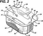
図1を参照すると、成形された合成樹脂容器12、カバーシート14、および容器12の収納領域18内に収納されたひげ剃りカートリッジ16を含む密封包装10が示されている。図2は、カバーシート14を取り付ける前の容器12を示している。容器12は収納領域18への入口22を囲む密封表面20を有しており、かつカバーシート14はこの密封表面20に封着される。(図1にその1つだけが示されている)合成樹脂タブ24は、カバーシート14の2つの角部の下面に取り付けられている。合成樹脂タブ24は、シート14の剥離を開始するために用いられる。剥離の前に、合成樹脂タブ24は、容器12の片側に沿って延びるリップ28の末端に配置された切欠部分26(図1)に配置されている。図2から分かるように、曲線状の切れ目29がタブ24とリップ28との間にある。
【0018】
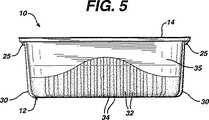
図1から図7を参照すると、容器12は、2つの端面(図1、図2および図7)上の指掴み用隆起30と、前側表面35(図1、図2、図5および図7)上の垂直掴み部34を与える浮き彫り部32と、後側表面40(図6および7)上の掴み用隆起38を与える浮き彫り36を有している。おそらくは図7の底面図から最も良く判るように、ユーザの指をよりよく収めるために掴み用隆起の最も外側の表面が全体的にくぼんだ輪郭を有するように、末端側の掴み用隆起30は中央の掴み用隆起30よりもさらに遠くまで外方へ延びている。
【0019】
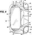
図2および図4は、ひげ剃りカートリッジ16を装填してその上にシート14を封着する前の合成樹脂容器12を示している。製造時のこの段階においては、合成樹脂タブ24は容器12の一部であり、(図4および図8に最も良く示されている)内側のブリッジ部材46によって容器に接続されている。ブリッジ部材46は、薄くて折れやすい部材であるが、密封前の取り扱い中にタブ24を所定位置に保持するには十分に強く、ユーザがカバー14の剥離を始めるためにタブ24を持ち上げるときには容易に折れる程度に充分に弱い。(これに代わるブリッジ部材を提供するために、リップを機械的に除去するか、少なくとも部分的に切断することができる。)タブ24は、ユーザの指による掴みを容易にするために外側端部の周辺隆起25を有している(図5、図6および図7参照)。
【0020】
図1〜図4を参照すると、リップ28が容器の側壁48に、カートリッジ16のカートリッジ接続構造52(図1)に導くための傾斜構造50によって接続されていることがわかる。適当なカートリッジ16は、1998年4月24日に出願された米国特許出願第09/066,499号に記載されているが、その内容はこの引用によって本願明細書に組み込まれる。米国意匠特許D407,851号は、カートリッジ16と嵌合するハンドルを記載している。ひげ剃りハンドル(図13)のカートリッジ16への接続の間、ハンドルの接続端がリップ28上に持って来られると、傾斜部分50はハンドルの端部を接続構造52(図1)に案内しようとする。カートリッジ16に接続されるとハンドルは引き出されれ、カートリッジ16が容器12から取り出される。リップ28は、容器12から引き出す間にユーザの親指および他の指をカートリッジ16の刃によって切れることから保護する。
【0021】
図3および図4を参照すると、容器12が、湾曲して凹状の上側表面53を有した2つの支持部材51を備えていることがわかる。これの部材51は、所望の位置にカートリッジ16を支持するためにカートリッジ16の刃ユニット上面の輪郭に整合している。支持部材51は、カートリッジ16の刃の外側で、カートリッジ16の端部を支持している。容器12内に収納されると刃の切刃は下側を向く。係合突起(戻り止め)54、56が各側壁48,58から内側に突出している。両係合突起54,56は、入口22を向いた上側傾斜面60および底部壁64を向いた下側傾斜面62を有している。カートリッジが容器12に装着されるときには、上側斜面60上を移動して係合突起54、56を(スナップ動作で)ぱちんと通り過ぎる際に、カートリッジは容器の壁をわずかに変形させる。容器12からの取り出しの間、カートリッジが斜面62を通過するときにも、カートリッジは容器の壁をわずかに変形させる。係合突起54はカートリッジ16のガード部分を下向きに保持すると共に、係合突起56はひげ剃りカートリッジのキャップ部分を下向きに保持する。
【0022】
製造の際には、容器12はポリプロピレンから射出成形される。容器12のために用い得るその他の材料には、ポリスチレン(特に結晶性ポリスチレン)、耐高衝撃性ポリスチレン(HIPS)、または耐中衝撃性ポリスチレン(MIPS)、ポリカーボネート、アクリロニトリルブタジエンスチレン(ABS)、ナイロンおよびスチレンアクリロニトリルコポリマー(SAN)が含まれる。ポリプロピレン以外の材料を用いる際に、当業者は(図12に示されるとともに後述される)密封層118にとって適切な密封層材料を選択する。容器12を成形した後、カートリッジ16は、その接続構造52がリップ28近傍の傾斜部50に隣接するような所望の接続位置において、刃ユニットが係合突起54、56を(スナップ動作で)ぱちんと通り過ぎて上側表面53上に載置されるようにして、容器12内に装填される。それから、カバーシート14が、上側シール面20および合成樹脂タブ24の上側表面にヒートシールによって封着される。これに代えて高周波溶着、超音波溶着または感圧接着剤を用いることができる。
【0023】
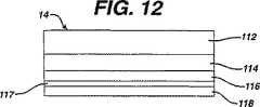
容器12は、内部のカートリッジの目視検査を可能とするように、透明な合成樹脂で作られている。カバーシート14は印刷可能であり、開封およびカートリッジの使用法の説明を載せることができる。カバーシート14は(異なる縮尺で)図12に示すラミネートからできている。このラミネートは、0.48ミル(0.012mm、48ゲージ)厚の(反転印刷される)ポリエチレンテレフタレート(PET)製の上側層112と、その下側の0.50ミル(0.013mm、50ゲージ、若しくは「7.5ポンド/連」と称される)厚の(好ましくは低密度の)ポリエチレン層114(好ましくは不透明とするために白色であるが、透明にしてもよい)と、その下の1.15ミル(0.029mm、115ゲージ)厚の配向された高密度ポリエチレン(HDPE)層116と、その下の約0.1ミル(「2ポンド/連」と称される)厚のポリエステルウレタン接着剤層117と、その下の1.25ミル(0.32mm)厚の同時押出された低密度ポリエチレン−エチレンビニルアセテート(LDPE-EVA)(28%)の封着層118とで構成され、下側のエチレンビニルアセテート(EVA)部分が容器12に封着される。
【0024】
このカバーシート14においては、高密度ポリエチレン(HDPE)層と、それより小さな限度において低密度ポリエチレン(LDPE)層とが、水分に対するバリヤ特性(防湿性)および折返し状態保持特性を与える。ポリエチレンテレフタレート(PET)は、嵩の高さと透明性および、その下側表面の印刷への保護を与える。ポリエチレンテレフタレート(PET)はまた、破れを防止するとともに1つの片としての取り外しをもたらすための構造的な一体性をラミネートに与える。ポリエチレンテレフタレート(PET)は、層間剥離することなしに24時間の華氏100度の温水浴条件下での促進試験に耐えるように選択される。ポリエチレン層(好ましくは低密度ポリエチレン(LDPE))は、高密度ポリエチレン(HDPE)層とポリエチレンテレフタレート(PET)層とを接合するための接着層として作用する。ポリエチレンテレフタレート(PET)は、ポリエチレンテレフタレート(PET)と高密度ポリエチレン(HDPE)との間の接着層として(華氏約600度の)高熱が負荷される低密度ポリエチレン(LDPE)との使用のために化学的に準備されている。
【0025】
ポリエチレン層(好ましくは低密度ポリエチレン(LDPE))は、好ましくは不透明であり、特に印刷のための背景色を与えるために白色であり、かつ密封による熱の影響を受ける領域と、シール面からほど遠い領域との間に、審美的により一様な外観をもたらすためには不透明である。ポリエステル-ウレタン層117は、とても薄くて1ミル未満、好ましくは約0.1ミルであるが、高密度ポリエチレン(HDPE)層116と低密度ポリエチレン−エチレンビニルアセテート(LDPE-EVA)密封層118とを接合するための接着層として作用する。層118の低密度ポリエチレン−エチレンビニルアセテート(LDPE-EVA)は、容器12のポリプロピレンに対する密封を提供するために特に適している。密封層118内のエチレンビニルアセテート(EVA)の量を容器12の材料に応じて変化させられることが分かる。さらに、高周波若しくは超音波溶着を用いる場合には別個の下側密封層118を省けることが分かる。密封層118は好ましくは1.25ミルより厚くなく、さもなければその嵩が、剥離状態を保つための高密度ポリエチレン(HDPE)層の折返し状態保持能力を上回ってしまう。
【0026】
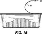
ラミネートのための「折返し状態保持」特性は、低密度ポリエチレン(LDPE)および高密度ポリエチレン(HDPE)層、主として高密度ポリエチレン(HDPE)層によってもたらされる。この折返し状態保持特性とは、カバーシート14が、容器12に依然として取り付いている部分を残して剥がされ、次いでユーザの手から解放されたとき、カートリッジへの容易なアクセスを許容するために、図13ないし図16に示されるようにシート14が後方に折り返されたまま若しくは後方に曲げられたままとなることである。格納された物品にユーザの手がアクセスする場合には、折返し状態保持特性とは、内側の物品にアクセスするときに手の指が実質的に妨害されないということである。
【0027】
一般的には、図16に示されるように、折返し状態への充分な保持は、取り外された部分と密封表面22との間の角度が30度、最も好ましくは(模式的に点線で描かれているように)45度よりも大きいときに起こる。他の観点によると、図15または図16の実施例に示されるように、充分な折返し状態への保持とは、カバーシートの取り外された部分が容器の入口領域の少なくとも半分を露出させる位置よりも後方に残ることで、収納された物品に対する実質的に妨げられないアクセスを許容することに帰着する。好ましくは、図15に示されるように、カバーシートの取り外された部分は側面間の半分の位置において容器を貫通する中線の後方に残る。特に、カバーシート14は、カートリッジに接続するときにハンドルが実質的に妨げられず、かつカートリッジを実質的に妨害なしに取り除くことができる程度に、後ろ側に十分に折り返されたままとなる。
【0028】
水蒸気に対するバリヤ特性(防湿性)は、低密度ポリエチレン(LDPE)および高密度ポリエチレン(HDPE)層、主として高密度ポリエチレン(HDPE)層によってもたらされる。水分に対するシートのバリヤ特性(防湿性)は、水蒸気通気率(MVTR)によって表すことができる。この水蒸気通気率(MVTR)は、華氏100度(摂氏37.8度)で相対湿度が90%の状態下において24時間につき100平方インチあたり約0.16グラム以下の水分量であることが好ましい。
【0029】
低密度ポリエチレン(LDPE)層と共に高密度ポリエチレン(HDPE)層を使用することは、折返し状態保持特性と水分バリヤ特性との所望の組み合わせを有利に提供する。さらにカバーシートは、外側のポリエチレンテレフタレート(PET)層と高密度ポリエチレン(HDPE)層との間にサンドイッチされる低密度ポリエチレン(LDPE)層の使用によって改善され、破れに対する抵抗力および印刷の完全性のようなフィルムの完全性を保護するための追加の利点が与えられる。
【0030】
カバー14における、金属箔ではなく合成樹脂のシート構造は、それが電子商品監視(EAS)要件を満たすので好ましい。電子商品監視(EAS)システムにおいては、お金を支払っている客が店を出るときに警報を解除するように、製品上の(一般的にそれらの内部に金属を含んでいる)小さなタグが支払時に不活性化される。ひげ剃りカートリッジを含んでいる容器上に金属箔が用いられると、金属箔と金属刃との接近した組み合わせが電子商品監視(EAS)タグの適切な機能と対立することがある。
【0031】
カバーシート14は、構造の一体性を維持するとともに層間剥離せず、取り外されるときに破れず(すなわち1つの片として取り外し可能であり)、水および(例えば浴槽内に用い得る)家庭用洗剤若しくはひげ剃り用前処理製品が存在しても劣化せず、その中に格納される物品を水分および洗剤から保護し、製品取り出しの容易さのための所望の折返し状態保持特性を有し、公知の金属箔よりも高価ではなく、印刷可能であり、かつ電子商品監視(EAS)システムと干渉しない。
【0032】
カバーシート14は、予め定められた初期剥離力を有するように容器12に固着される。剥離力は、角部のタブが下方を向くと共にその角部から反対側の角部への対角線が鉛直方向に位置合わせされた状態でカバーシート14が鉛直面内にあってるように容器12を支持することによって決定される。容器12は取付具によってこの位置に維持されるが、下側の角部のタブは(Instronという登録商品名で入手可能な)力と距離との関係を測定する機械に接続され、かつこの機械によって上方に引き上げられる。その結果として得られる力と距離との関係を表すグラフは典型的に、密封温度が160℃〜215℃のときに約3〜5ポンド(13.6〜22.7N)である単一のピークを有するが、それが重要な初期剥離力である。好ましい密封温度は、約175℃である。
【0033】
使用の際にユーザは、ブリッジ部分46を折るために合成樹脂タブ24を曲げると共に、剥離を始めるためにカバーシートの表面に沿ってタブ24を後方に引っ張る。ユーザは、容器の2つの端部における掴み用隆起30を掴むことができるし、その代わりに前面および後面の隆起34、38を掴むこともできる。次いでユーザは、(図示しない)ハンドルをカートリッジの接続構造52に接続してカートリッジ16を取り出す。係合突起56は、カートリッジ16が取り出されるときに支点として作用する。前方および後方の隆起34、38がユーザによって握持される場合、リップ28は、カートリッジの取り出しの間にユーザの親指または指が刃によって切れることから保護する。
【0034】
本発明のその他の実施例は特許請求の範囲内にある。例えば(好ましい実施例を描いている)図9は、仮設の接続構造を提供するための、容器12のタブ24および側面から外側に延びる輪状部分100の使用を示している。カバーシートが容器12およびタブ24に封着された後に、輪状部分100は、容器12の側面ないしリップ28の端部に対して平行な一回の切断によって切り取ることができる。加えて、タブ24および容器は同一の材料ないしは異なる材料から作ることができ、かつ仮設の接続部、例えば輪状部分100は同一の材料ないしは異なる材料から作ることができる。タブは、より良好な掴み表面を提供するためにエラストマ材料で作ることができる。ある角度を有する係合突起54、56に加えて、カートリッジを所望の位置に保持するためにその他の突出構造を用いることができる。カバーシート14は、いくつかの用途において所望の折返し状態保持特性を有する金属箔から作ることができる。
【図面の簡単な説明】
【図1】 部分的に開けられた状態で、内部のひげ剃りカートリッジと共に示す密封包装の斜視図。
【図2】 図1の包装における成形された合成樹脂容器を示す斜視図。
【図3】 図2中の3−3線に沿った図2の包装の断面図。
【図4】 図2の合成樹脂容器の平面図。
【図5】 図2の合成樹脂容器の正面図。
【図6】 図2の合成樹脂容器の背面図。
【図7】 図2の合成樹脂容器の底面図。
【図8】 図4の容器の接続ブリッジ構造を示す、図4の8−8線に沿った部分断面図。
【図9】 他のブリッジ構造を示す要部平面図。
【図10】 従来技術の密封された食品容器を示す図。
【図11】 従来技術の密封された食品容器を示す図。
【図12】 図1の包装の取り外し可能なフィルムの積層構造を示す図。
【図13】 図1の包装内に収納されたひげ剃りカートリッジに接続されるハンドルを示す図。
【図14】 図1の包装内に収納されたひげ剃りカートリッジに接続されるハンドルを示す図。
【図15】 図3の包装の開けられたカバーシートを、安定した第1の典型的な剥離状態で示す図。
【図16】 図3の包装の開けられたカバーシートを、安定した第2の典型的な剥離状態で示す図。[0001]
The present invention relates to a container for storing items such as a shaving cartridge.
[0002]
Shaving cartridges are typically sold in a synthetic resin dispenser that includes a plurality of shaving cartridges disposed in portions within the container.
[0003]
In the technology for packaging snacks and seasonings, a synthetic resin container that is formed into a generally open box-shaped rectangular shape having an outer peripheral edge and is covered with a synthetic resin foil that is sealed to the edge And a triangular shape shaped so that one corner of the edge is diagonally sheared with a knives knife so as to leave little space between adjacent edges and remain attached to the sealing foil It is well known to have a pull tab. For example, such containers are used in container snacks available in the United States under the registered trade name “Phileas Fogg”.
[0004]
Such prior art containers are depicted in the accompanying FIGS. As understood by the applicant of the present application, a
[0005]
Prior art recognized in this way is also available in the United States under the name of plastic containers for butter-sized butter or Knotts Berry Farm Foods, Inc. (Placencia, CA) Has foldable metal foil used to cover similar containers for seasonings or preserved foods, but these containers also have corner pull tabs provided by slitting the edges ing. This laminate cover foil is understood to be a thin metal foil whose outer side is coated with a synthetic resin (printed with a graphic) and has a lower layer of heat seal adhesive. This synthetic resin coating merely provides barrier properties against moisture and gas. These container foils can be peeled back, but must be made of metal to allow permanent deformation.
[0006]
Prior art recognized in this way is, for example, hot melt bonding, which is considered to be available in the United States under the name of Yoplait and is used for six packages each supplying yogurt It further comprises a paper layer coated with polyester with a lower sealing material layer such as an agent. This polyester aids removal as a single piece. Paper has the minimum ability to remain folded back, but is an absorbent material and lacks barrier properties (moisture resistance) against moisture.
[0007]
French Patent 2,714,031 discloses a food container with means for ensuring proper orientation of the material within the container. It is provided with a cover film.
European patent EP-A-0548785 relates to photographic film packaging for protecting the packaged contents against moisture, dust and light. The lid can be a metal foil to seal the package in a sealable manner and provide folded state retention properties, and can also be a laminate that does not include a foil to provide barrier properties (moisture resistance) to moisture.
German Patent 19751428 discloses a container sealed by a film having a tear tab created in the flange region by incision or perforation.
[0008]
According to the present invention, a synthetic resin container that defines a storage area and has a sealing surface around an entrance to the area, and is integrally molded on the bottom wall and protrudes inwardly therefrom. At least two opposing side walls each having a retaining structure that moves outwardly to allow entry of the cartridge into the storage area and thereafter places the cartridge into the area. A container that can be moved inwardly to hold, a shaving cartridge that is contained within the storage area and is held by the holding structure, the cartridge including a synthetic resin housing and a plurality of blades; A sealed package is provided comprising a removable film sealed to the sealing surface and covering the inlet.
According to another aspect of the present invention, a molded synthetic resin container defining a storage area defined by a bottom wall and a sidewall extending upwardly from the bottom wall, the inlet to the storage area And having a length and width and a container longitudinal axis along the length, at least one side wall of which is a longer longitudinal side wall extending along the container longitudinal axis, And at least one of the side walls is a container such that the side wall is a short side wall extending in a direction transverse to the longitudinal axis of the container, and a shaving cartridge in a position to be connected to a handle in the storage area. A cartridge having a synthetic resin housing and a plurality of blades, and having a length and width, and a cartridge longitudinal axis along the length aligned with the longitudinal axis of the container. And is formed adjacent to the longer longitudinal side wall and the long at the inlet to separate the user's thumb or other finger from the inlet during removal of the cartridge from the area. A packaging is provided, comprising a longitudinal side wall and a synthetic resin lip extending integrally therewith.
According to another aspect of the present invention, a synthetic resin container defining a storage area and having a sealing surface around an entrance to the area, and a synthetic resin in a position to be connected to a handle in the storage area A shaving cartridge having a housing and a plurality of blades; and a removable film having at least one synthetic resin layer sealed to the sealing surface to cover the inlet and having folded-back properties. A hermetically sealed package is provided.
According to another aspect of the present invention, the main area defining the storage area and having a sealing surface around the entrance to the area, having a first opposing end surface along a portion thereof and facing outward. A synthetic resin container having a surface, a removable unit as a whole unit stored in the storage area, a removable film sealed to the sealing surface and covering the inlet, and the molded A synthetic resin tab separated from the synthetic resin container by a break and attached to a portion of the film extending beyond the sealing surface for a user to grip the film and initiate release from the sealing surface; And the tab has a second opposing end surface that faces the first opposing end surface along a part of the tab, and the cut is defined by each opposing end surface. Extends Te, the extends from the main surface of the container to the film and has been a direction parallel to the axis arrangement parallel surfaces, it is provided a packaging, characterized in that.
According to another aspect of the present invention, a molded synthetic resin container defining a storage area defined by a bottom wall and a side wall having a side surface and having an inlet to the storage area; A unit detachable as a whole unit stored in the storage area, formed inside the container and extending inward from the side surface, holding the unit at a desired position in the container; and A holding structure that can move outward to allow entry of the unit into a storage area and then move inward to hold the cartridge in the area, and is sealed to the sealing surface And a removable film covering the inlet.
According to another aspect of the present invention, a molded synthetic resin container defining a storage area, a container edge, and a sealing surface around the entrance to the area, and adjacent to the sealing surface , A synthetic resin tab having a tab end adjacent to the container edge, and a first temporary connector for connecting the tab to the synthetic resin container, the first temporary connector from the tab edge A first portion extending in a transverse direction; a second portion extending generally from the first portion parallel to the container edge and the tab edge; and from the container edge to the second portion. A third portion extending transversely to the first temporary connector so that the first temporary connector can be cut by a single cut parallel to the container edge and the tab edge. There are packaging parts characterized by It is.
[0009]
According to another aspect of the invention, the storage area and the sealing surface around the entrance to the area are defined, and the storage area is defined by at least two opposing side walls each having a retaining structure protruding inwardly. Preparing a synthetic resin container to be formed; arranging a shaving cartridge including a synthetic resin housing and a plurality of blades in the storage area; and allowing the cartridge to enter the storage area Storing the shaving cartridge by contacting the shaving cartridge with the holding structure that can be moved outwardly and then moved inward to hold the cartridge in the region. Holding in the area and sealing a removable film to the sealing surface over the inlet. Method for manufacturing a sealed package, characterized in Rukoto is provided.
According to the present invention, preparing a synthetic resin container that defines a storage area and a sealing surface around the entrance to the area, and disposing a unit removable as a whole unit in the storage area; Sealing a removable film to the sealing surface to cover the inlet and one of the films extending beyond the sealing surface to initiate peeling of the film from the sealing surface. Attaching a synthetic resin tab provided at a first position adjacent to the sealing surface to the part, connecting the synthetic resin tab to the container with a temporary connector, sealing, and attaching Separating the temporary connector and leaving the tab in the first position adjacent to the sealing surface; and Granulation method is provided.
According to the present invention, a molded synthetic resin container that houses a shaving cartridge in a storage area, and a removable film that is sealed to a sealing surface around the entrance to the storage area in the container, Providing a sealed package such that the cartridge has a plastic housing and a plurality of blades and is held by a retaining structure molded on the wall of the container; and to provide access to the shaving cartridge A method of providing a shave cartridge on a shave comprising: peeling the film from the sealing surface; attaching the cartridge to a handle; and releasing the cartridge from the holding structure. Provided.
According to the present invention, a molded synthetic resin container that houses a shaving cartridge in a storage area, and a removable film that is sealed to a sealing surface around the entrance to the storage area in the container, The film has a plurality of synthetic resin layers formed structurally without a metal layer, and the cartridge has a synthetic resin housing and a plurality of blades to prepare a sealed package; and Peeling the film from the sealing surface to provide access to a shaving cartridge; and attaching the cartridge to a handle, the peeling step including removing the film when the peeling force is removed. Including being attached to a surface and remaining folded so as not to interfere with the attachment. A method of providing a lower shaving cartridge on shaving is provided.
[0010]
In one embodiment, the sealed package is sealed to a molded synthetic resin container, a shaving cartridge (or other stored unit) within the container storage area, and a sealing surface around the entrance to the storage area. And a removable film covering the storage area. The side wall of the container has a holding structure that protrudes inward to hold the shaving cartridge (or other stored unit).
In other embodiments, the hermetic package houses the shaving cartridge in a molded plastic container that is sealed by a removable film. The container has a lip adjacent to and extending from the side wall of the container at the entrance of the storage area to separate the user's thumb or other finger from the entrance during removal of the cartridge.
In another embodiment, the hermetic package houses the shaving cartridge in a molded synthetic resin container that is sealed by a removable film. The film has folded properties that facilitate removal of the cartridge when it is still partially connected to the rear of the container.
In another aspect, hermetic packaging houses the unit to be stored in a molded plastic container that is sealed by a removable film. The synthetic resin tab is attached to a portion of the film that extends beyond the sealing surface of the container to initiate release from the sealing surface of the film. The synthetic resin tabs are arranged with a gap from the molded synthetic resin container.
[0011]
Particular embodiments of the invention can include one or more of the following features. The blade of the cartridge faces away from the entrance to the storage area. The container has a support member on the bottom wall that supports the cartridge in a desired orientation, and the support member has a curved surface that matches the contour of the upper surface of the cartridge. The cartridge holding structure on the side wall of the container has a surface that slopes toward the inlet and bottom wall of the container. The container is transparent. The container has a plurality of finger grip ridges protruding on one or more outer surfaces, and these ridges have a contour that is recessed on the user's finger to fit on several surfaces thereof. The synthetic resin tab connected to the removable film has a gripping ridge extending from its surface. The synthetic resin tab is disposed in the cutout portion of the lip of the container. The tab has a half-moon shape. The removable film is more flexible than the wall of the molded plastic container. The film is sealed to the container with a removal force greater than 1.5 Newtons (preferably 3-5 Newtons). The film carries the print on the inner surface between the film layers. The film is heat sealed or radio frequency (RF) welded to the sealing surface of the container.
[0012]
In another aspect, the present invention generally includes a synthetic resin container defining a storage area and a sealing surface around an entrance to the area, a synthetic resin tab adjacent to the sealing surface, and connecting the tab to the synthetic resin container. It features a packaging part including a temporary connector.
[0013]
Particular embodiments of the packaging component have one or more of the following features. The temporary connector includes a first portion extending transversely from the tab edge, a second portion extending generally from the first portion and the tab edge parallel to the container edge, and the container edge. A third portion extending transversely to the second portion, resulting in a ring-shaped connector. The temporary connector is molded simultaneously with the molded synthetic resin container and the tab. On the other hand, the temporary connector can be a bridge portion where the synthetic resin is easily broken.
[0014]
In another aspect, the invention generally features a method of manufacturing the described sealed package and a method of using the described sealed package.
[0015]
Embodiments of the invention can include one or more of the following advantages. This hermetic package protects the cartridge from moisture, pre-shaving products such as soap, foam or gel, and detergent when stored in the shower or bath tub area prior to use. The annular bridge member can be easily separated by a single cut along the outside of the package. The inclined surface guides the cartridge to the desired position when loaded into the storage area. The support member and the holding structure hold the cartridge in a desired position for attachment to the handle. The synthetic resin tab provides a good gripping member to begin peeling. The folded state retention feature prevents the partially removed foil from interfering with the connection of the cartridge to the handle. The inclined structure guides the handle to the connecting portion of the cartridge housed in the container. The lip protects the user's thumb or other finger from the cutting edge of the blade during removal of the cartridge from the container.
[0016]
Other advantages and features of the invention will be apparent from the following detailed description of the embodiments of the invention and from the claims.
[0017]
Referring to FIG. 1, a
[0018]
Referring to FIGS. 1-7, the
[0019]
2 and 4 show the
[0020]
1-4, it can be seen that the
[0021]
3 and 4, it can be seen that the
[0022]
During manufacture, the
[0023]
The
[0024]
In this
[0025]
The polyethylene layer (preferably low density polyethylene (LDPE)) is preferably opaque, especially white to give a background color for printing, and is far from the sealing surface and the heat affected area due to sealing It is opaque to provide an aesthetically more uniform appearance between the areas. The polyester-
[0026]
The “folded state retention” property for the laminate is provided by low density polyethylene (LDPE) and high density polyethylene (HDPE) layers, primarily high density polyethylene (HDPE) layers. This folded state retention characteristic is illustrated in order to allow easy access to the cartridge when the
[0027]
In general, as shown in FIG. 16, sufficient retention in the folded state is that the angle between the removed portion and the sealing
[0028]
Barrier properties against moisture (moisture resistance) are provided by low density polyethylene (LDPE) and high density polyethylene (HDPE) layers, primarily high density polyethylene (HDPE) layers. The barrier property (moisture resistance) of the sheet with respect to moisture can be expressed by the water vapor permeability (MVTR). The water vapor permeability (MVTR) is preferably less than about 0.16 grams per 100 square inches per 24 hours under conditions of 100 degrees Fahrenheit (37.8 degrees Celsius) and 90% relative humidity. .
[0029]
The use of a high density polyethylene (HDPE) layer with a low density polyethylene (LDPE) layer advantageously provides the desired combination of folded state retention properties and moisture barrier properties. The cover sheet is further improved by the use of a low density polyethylene (LDPE) layer sandwiched between an outer polyethylene terephthalate (PET) layer and a high density polyethylene (HDPE) layer, resistance to tearing and printing integrity. An additional advantage is provided for protecting the integrity of the film.
[0030]
A synthetic resin sheet structure, rather than a metal foil, in the
[0031]
The
[0032]
The
[0033]
In use, the user bends the
[0034]
Other embodiments of the invention are within the scope of the claims. For example, FIG. 9 (illustrating a preferred embodiment) illustrates the use of
[Brief description of the drawings]
FIG. 1 is a perspective view of a sealed package shown with an internal shaving cartridge in a partially opened state.
FIG. 2 is a perspective view showing a synthetic resin container molded in the packaging of FIG.
3 is a cross-sectional view of the package of FIG. 2 taken along line 3-3 in FIG.
4 is a plan view of the synthetic resin container in FIG. 2;
FIG. 5 is a front view of the synthetic resin container in FIG. 2;
6 is a rear view of the synthetic resin container in FIG. 2;
7 is a bottom view of the synthetic resin container of FIG. 2. FIG.
8 is a partial cross-sectional view taken along line 8-8 of FIG. 4, showing the connection bridge structure of the container of FIG.
FIG. 9 is a plan view of a main part showing another bridge structure.
FIG. 10 shows a prior art sealed food container.
FIG. 11 shows a prior art sealed food container.
12 is a view showing a laminated structure of the removable film of the package of FIG. 1. FIG.
13 is a view showing a handle connected to a shaving cartridge housed in the package of FIG. 1. FIG.
14 is a diagram showing a handle connected to a shaving cartridge housed in the package of FIG. 1. FIG.
FIG. 15 is a view showing the opened cover sheet of FIG. 3 in a stable first typical peeled state.
FIG. 16 is a view showing the opened cover sheet of FIG. 3 in a stable second typical peeled state.
Claims (49)
Translated fromJapanese前記収納領域への入口、底部壁と、その上に一体的に成形されると共に内側に突出する保持構造をそれぞれ有した少なくとも2つの対向側壁とを有し、前記保持構造は、前記収納領域へのカートリッジの進入を許容するために外側に移動すると共に、その後に前記カートリッジを前記領域内に保持するために内側に移動することができるような容器と、
前記収納領域内に含まれると共に前記保持構造によって保持されるひげ剃りカートリッジであって、合成樹脂ハウジングおよび複数の刃を含むカートリッジと、
密封表面に封着されて前記入口を覆う取り外し可能なフィルムと、
を備えることを特徴とする密封包装体。In a sealed package with a molded synthetic resin container defining a storage area,
An inlet to the storage area, a bottom wall, and at least two opposing sidewalls each integrally formed thereon and having a holding structure protruding inward, the holding structure to the storage area A container that can be moved outward to allow entry of a cartridge of the cartridge and then moved inward to retain the cartridge in the region;
A shaving cartridge contained in the storage area and held by the holding structure, the cartridge including a synthetic resin housing and a plurality of blades;
A removable film sealed to a sealing surface and covering the inlet;
A hermetically sealed package comprising:
前記収納領域内でハンドルと接続されるべき位置にあるひげ剃りカートリッジであって、合成樹脂ハウジングおよび複数の刃を有し、かつ長さおよび幅と、前記容器の長手方向軸線と整列する前記長さに沿ったカートリッジ長手方向軸線とを有するカートリッジと、
前記長い方の長手方向側壁に隣接して成形されると共に、前記領域からの前記カートリッジの取り出しの間に前記入口からユーザの親指ないし他の指を離間させるために前記入口において前記長い方の長手方向側壁と一体に延びる合成樹脂リップと、
を備えることを特徴とする包装体。An elongate synthetic resin container having a molded longitudinal axis defining a storage area defined by a bottom wall and a sidewall extending upwardly from the bottom wall, having an inlet to the storage area And a length and width and a container longitudinal axis along the length, at least one side wall of which is a longer longitudinal side wall extending along the container longitudinal axis, and A container wherein at least one of the side walls is a shorter side wall extending transversely to the container longitudinal axis;
A shaving cartridge in a position to be connected to a handle within the storage area, the shaving cartridge having a synthetic resin housing and a plurality of blades, the length and width being aligned with a longitudinal axis of the container A cartridge having a cartridge longitudinal axis along the length;
The long longitudinal at the inlet is molded adjacent the long longitudinal side wall and separates the user's thumb or other finger from the inlet during removal of the cartridge from the area. A synthetic resin lip extending integrally with the directional side wall;
A package characterized by comprising.
前記収納領域内で外方から侵入するハンドルと接続されるべき位置にある、合成樹脂ハウジングおよび複数の刃を有したひげ剃りカートリッジと、
前記密封表面に封着されて前記入口を覆い、折返し状態保持特性を有する少なくとも一つの合成樹脂層を有した、取り外し可能なフィルムと、
を備えることを特徴とする密封包装体。A synthetic resin container defining a storage area and having a sealing surface around the entrance to the area;
A shaving cartridge having a synthetic resin housing and a plurality of blades in a position to be connected to a handle penetrating from the outside in the storage area;
A removable film having at least one synthetic resin layer sealed to the sealing surface to cover the inlet and having folded-back properties;
A hermetically sealed package comprising:
かつ前記保持構造は、前記支持体部材より高い位置において前記容器の前記側壁上に配置されている、
ことを特徴とする請求項1に記載の包装体。The container has a support member on the bottom wall for supporting the cartridge in a desired direction,
And the holding structure is arranged on the side wall of the container at a position higher than the support member.
The package according to claim 1.
前記容器は、前記リップを前記側壁に接続すると共に前記カートリッジを前記領域内に案内する傾斜構造を有し、
かつ前記カートリッジを所望の向きで支持するための前記底壁上にある複数の支持部材と、
前記互いに対向側壁から突出して前記ひげ剃りカートリッジを前記容器内の所望の位置に保持する保持構造と、
をさらに備えることを特徴とする請求項2に記載の包装体。The side walls have opposing side walls;
The container has an inclined structure that connects the lip to the side wall and guides the cartridge into the region;
A plurality of support members on the bottom wall for supporting the cartridge in a desired orientation;
A holding structure that protrudes from the opposing side walls and holds the shaving cartridge in a desired position in the container;
The package according to claim 2, further comprising:
かつ前記隆起はユーザの指を収容するためにくぼんだ輪郭を有している、
ことを特徴とする請求項1または2に記載の包装体。The container has a plurality of ridges for gripping with fingers, protruding on one or more outer surfaces;
And the ridge has a recessed profile to accommodate a user's finger,
The package according to claim 1 or 2, wherein
前記タブは、その外側部分の周りで表面から延びる掴み用隆起を有している、
ことを特徴とする請求項1または3に記載の包装体。Further comprising a synthetic resin tab attached to a portion of the film extending beyond the sealing surface for initiating peeling of the film from the sealing surface;
The tab has a gripping ridge extending from the surface around its outer portion;
The package according to claim1 or 3 , wherein
合成樹脂ハウジングと複数の刃とを含んだひげ剃りカートリッジを前記収納領域内に配置する段階と、
前記収納領域への前記カートリッジの進入を許容するために外側に移動すると共にその後に前記カートリッジを前記領域内に保持するために内側に移動することができる前記保持構造を、前記ひげ剃りカートリッジに接触させることによって、前記ひげ剃りカートリッジを前記収納領域内に保持する段階と、
取り外し可能なフィルムを、前記入口を覆うように前記密封表面に封着する段階と、
を備えることを特徴とする密封包装体の製造方法。A synthetic resin container is provided that defines a storage area and a sealing surface around an entrance to the area, and the storage area is defined by at least two opposing side walls each having a holding structure protruding inwardly. And the stage of
Placing a shaving cartridge including a synthetic resin housing and a plurality of blades in the storage area;
Contact the shaving cartridge with the holding structure that can move outward to allow the cartridge to enter the storage area and then move inward to hold the cartridge in the area. Holding the shaving cartridge in the storage area by:
Sealing a removable film to the sealing surface to cover the inlet;
A method for producing a sealed package, comprising:
かつ前記配置する段階は、前記カートリッジを前記支持部材上に配置することと、所望の向きで前記カートリッジを支持することを含む、
ことを特徴とする請求項27に記載の方法。The preparing step includes providing a support member on a bottom wall of the container;
And the step of placing includes placing the cartridge on the support member and supporting the cartridge in a desired orientation.
28. The method of claim27 .
前記封着する段階は、前記密封表面を越えて延びている前記フィルムの一部に前記タブを密封可能に取り付けることを更に含み、
かつ前記封着する段階の後に前記仮設コネクタを分離する段階を更に備えることを特徴とする請求項27に記載の方法。The preparing step includes providing a synthetic resin tab adjacent to the sealing surface connected to the container by a temporary connector;
The sealing further comprises sealably attaching the tab to a portion of the film extending beyond the sealing surface;
28. The method of claim27 , further comprising the step of separating the temporary connector after the sealing step.
かつ前記準備する段階は、前記合成樹脂タブおよび仮設コネクタを前記合成樹脂容器の成形と同時に成形することを含む、
ことを特徴とする請求項32に記載の方法。The temporary connector is made of synthetic resin,
And the step of preparing includes molding the synthetic resin tab and the temporary connector simultaneously with the molding of the synthetic resin container,
35. The method of claim32 .
かつ前記分離する段階は前記折れやすいブリッジ部分を折ることを含む、
ことを特徴とする請求項33に記載の方法。The temporary connector is a bridge part that is easy to break,
And the step of separating includes folding the breakable bridge portion.
34. The method of claim33 .
前記第1の仮設コネクタは、前記タブ縁部から外方に延びる第1の部分と、全体として前記容器縁部および前記タブ縁部に対して平行に前記第1の部分から延びる第2の部分と、前記容器縁部から前記第2の部分に対して外方に延びる第3の部分とを有し、
かつ前記分離する段階は、前記容器縁部に平行な一回の切断によって前記仮設コネクタを前記容器から切り取ることを含む、
ことを特徴とする請求項33に記載の方法。The tab has a tab edge aligned with the container edge. The first temporary connector includes a first portion extending outward from the tab edge, and the container edge and the tab edge as a whole. A second portion extending from the first portion parallel to the third portion and a third portion extending outwardly from the container edge with respect to the second portion;
And the step of separating includes cutting the temporary connector from the container by a single cut parallel to the container edge,
34. The method of claim33 .
前記ひげ剃りカートリッジへのアクセスをもたらすために前記密封表面から前記フィルムを剥がす段階と、
前記カートリッジをハンドルに取り付ける段階と、
前記保持構造から前記カートリッジを解放する段階と
を備えることを特徴とする、ひげ剃りカートリッジをひげ剃り上に設ける方法。A molded synthetic resin container that houses a shaving cartridge in a storage area, and a removable film that is sealed to a sealing surface around the entrance to the storage area in the container, the cartridge being a synthetic resin housing And providing a sealed package having a plurality of blades and being held by a holding structure molded on the wall of the container;
Peeling the film from the sealing surface to provide access to the shaving cartridge;
Attaching the cartridge to a handle;
Releasing the cartridge from the holding structure. A method of providing a shave cartridge on a shave.
前記ひげ剃りカートリッジへのアクセスをもたらすために前記密封表面から前記フィルムを剥がす段階と、
前記カートリッジをハンドルに取り付ける段階と
を備え、
前記剥がす段階は、剥離する力が取り除かれると、前記フィルムが前記密封表面に取り付けられかつ前記取り付けを妨げないように折り返されたままであることを含む、
ことを特徴とする、ひげ剃りカートリッジをひげ剃り上に設ける方法。A molded synthetic resin container that houses a shaving cartridge in a storage area; and a removable film that is sealed to a sealing surface around an entrance to the storage area in the container, the film being structurally Providing a sealed package having a plurality of synthetic resin layers molded without a metal layer, and wherein the cartridge has a synthetic resin housing and a plurality of blades;
Peeling the film from the sealing surface to provide access to the shaving cartridge;
Attaching the cartridge to a handle,
The peeling step includes that when the peeling force is removed, the film is attached to the sealing surface and remains folded so as not to interfere with the attachment.
A method for providing a shave cartridge on a shave.
かつ前記取り付ける段階は、前記ハンドルをカートリッジ接続構造に向かって移動させることを含む、ことを特徴とする請求項36に記載の方法。The step of preparing comprises preparing the cartridge with a handle connection structure of the cartridge facing upward and having a connection axis that is transverse to the inlet region;
The method of claim36 , wherein the attaching step includes moving the handle toward a cartridge connection structure.
Applications Claiming Priority (3)
| Application Number | Priority Date | Filing Date | Title |
|---|---|---|---|
| US09/364,242US6499595B1 (en) | 1999-07-29 | 1999-07-29 | Container for shaving cartridge or other stored item |
| US09/364,242 | 1999-07-29 | ||
| PCT/US2000/020067WO2001009002A2 (en) | 1999-07-29 | 2000-07-24 | Container for shaving cartridge or other stored item |
Related Child Applications (1)
| Application Number | Title | Priority Date | Filing Date |
|---|---|---|---|
| JP2011243514ADivisionJP2012071149A (en) | 1999-07-29 | 2011-11-07 | Container for shaving cartridge or other stored item |
Publications (2)
| Publication Number | Publication Date |
|---|---|
| JP2003506268A JP2003506268A (en) | 2003-02-18 |
| JP4942891B2true JP4942891B2 (en) | 2012-05-30 |
Family
ID=23433655
Family Applications (2)
| Application Number | Title | Priority Date | Filing Date |
|---|---|---|---|
| JP2001514214AExpired - LifetimeJP4942891B2 (en) | 1999-07-29 | 2000-07-24 | Shaving cartridges and containers for other items |
| JP2011243514APendingJP2012071149A (en) | 1999-07-29 | 2011-11-07 | Container for shaving cartridge or other stored item |
Family Applications After (1)
| Application Number | Title | Priority Date | Filing Date |
|---|---|---|---|
| JP2011243514APendingJP2012071149A (en) | 1999-07-29 | 2011-11-07 | Container for shaving cartridge or other stored item |
Country Status (23)
| Country | Link |
|---|---|
| US (4) | US6499595B1 (en) |
| EP (4) | EP1790586B1 (en) |
| JP (2) | JP4942891B2 (en) |
| KR (1) | KR100772769B1 (en) |
| CN (6) | CN100406357C (en) |
| AR (1) | AR029384A1 (en) |
| AT (2) | ATE529353T1 (en) |
| AU (2) | AU774147B2 (en) |
| BR (1) | BR0012770B1 (en) |
| CA (1) | CA2378311C (en) |
| CO (1) | CO5280036A1 (en) |
| DE (1) | DE60036386T2 (en) |
| DK (1) | DK1204567T3 (en) |
| ES (1) | ES2292458T3 (en) |
| HU (1) | HUP0202236A2 (en) |
| MX (1) | MXPA02000976A (en) |
| NZ (4) | NZ516628A (en) |
| PL (1) | PL202713B1 (en) |
| PT (1) | PT1204567E (en) |
| RU (2) | RU2250186C2 (en) |
| TW (1) | TW472021B (en) |
| WO (1) | WO2001009002A2 (en) |
| ZA (1) | ZA200110544B (en) |
Families Citing this family (150)
| Publication number | Priority date | Publication date | Assignee | Title |
|---|---|---|---|---|
| US6415517B1 (en)* | 1999-07-29 | 2002-07-09 | The Gillette Company | Storage device for shaving razor, cartridges, or other stored items |
| US6499595B1 (en) | 1999-07-29 | 2002-12-31 | The Gillette Company | Container for shaving cartridge or other stored item |
| EP1340693A1 (en)* | 2002-02-26 | 2003-09-03 | Cryovac, Inc. | Easy open package |
| US8038713B2 (en) | 2002-04-23 | 2011-10-18 | Spinecore, Inc. | Two-component artificial disc replacements |
| US20080027548A9 (en) | 2002-04-12 | 2008-01-31 | Ferree Bret A | Spacerless artificial disc replacements |
| AU2003212582A1 (en)* | 2002-05-07 | 2003-11-11 | Eveready Battery Company, Inc. | Container for replacement cartridge |
| EP1920894A1 (en)* | 2002-05-07 | 2008-05-14 | Eveready Battery Company, Inc. | Container for replacement cartridge |
| US7172779B2 (en) | 2002-09-27 | 2007-02-06 | Kraft Foods Holdings, Inc. | Container for sliced and fluffed food products |
| CA2511822C (en) | 2002-12-27 | 2011-06-28 | Noven Pharmaceuticals, Inc. | Product retention package |
| NL1022368C2 (en)* | 2003-01-13 | 2004-07-15 | H J Heinz Holding B V | Packaging. |
| US6908484B2 (en) | 2003-03-06 | 2005-06-21 | Spinecore, Inc. | Cervical disc replacement |
| GB0305663D0 (en)* | 2003-03-12 | 2003-04-16 | Ultraframe Uk Ltd | Base for a building structure |
| US20050077297A1 (en)* | 2003-10-09 | 2005-04-14 | Sonoco Development, Inc. | Container with easily removable membrane lid |
| US20070221218A1 (en)* | 2003-10-27 | 2007-09-27 | Warden Jeffrey A | Dry Powder Drug Containment System Packages with Tabs, Inhalers and Associated Methods |
| US20050198825A1 (en)* | 2004-03-11 | 2005-09-15 | Apprille Domenic V.Jr. | Dispensers for razor blade cartridges |
| US7178672B2 (en)* | 2005-05-03 | 2007-02-20 | Unilever Home & Personal Care Usa, Division Of Conopco, Inc. | Erect package |
| EP1896115B2 (en)* | 2005-06-27 | 2020-01-22 | 3M Innovative Properties Company | Microneedle cartridge assembly |
| US7810302B2 (en) | 2005-10-25 | 2010-10-12 | Kraft Foods Global Brands Llc | Method of forming reclose mechanism in a reclosable package |
| US20070164045A1 (en)* | 2006-01-13 | 2007-07-19 | Wydler Hans L | Dual mode container |
| DE102006005700A1 (en)* | 2006-02-08 | 2007-08-09 | Robert Bosch Gmbh | Apparatus and method for removing a cover sheet from a container |
| US7475780B2 (en)* | 2006-02-24 | 2009-01-13 | Kraft Foods Global Brands Llc | Reclosable food package having an easy-open feature |
| USD549574S1 (en) | 2006-06-16 | 2007-08-28 | The Gillette Company | Container |
| FR2904299B1 (en)* | 2006-07-27 | 2008-09-19 | Bongrain Sa | PACKAGING PARTICULARLY FOR FOOD PRODUCT COMPRISING A SOFT OPERATOR OVERLOADED WITH A COVER. |
| US8419713B1 (en) | 2012-08-01 | 2013-04-16 | The University Of Utah Research Foundation | Carrier assembly with caps for medical connectors |
| US8343112B2 (en) | 2009-10-30 | 2013-01-01 | Catheter Connections, Inc. | Disinfecting caps having an extendable feature and related systems and methods |
| US8328767B2 (en) | 2007-01-16 | 2012-12-11 | Catheter Connections, Inc. | Disinfecting caps for medical male luer connectors |
| USD558063S1 (en) | 2007-03-20 | 2007-12-25 | The Gillette Company | Razor cartridge container |
| USD579347S1 (en) | 2007-03-20 | 2008-10-28 | The Gillette Company | Razor cartridge container |
| US7798324B2 (en)* | 2007-04-17 | 2010-09-21 | Crescent Manufacturing Company | System and method for packaging cutting blades |
| US20080303855A1 (en)* | 2007-06-07 | 2008-12-11 | Alan Bidwell | Compliant Sealing Materials and Methods For Sealing Nozzles For A Micro-Fluid Ejection Head |
| US8051979B2 (en)* | 2007-06-28 | 2011-11-08 | Philip Morris Usa Inc. | Innovative packaging for consumer product |
| US8113347B2 (en)* | 2007-08-30 | 2012-02-14 | Gillette Company | Razor storage case having mating closure members |
| US8251219B1 (en) | 2007-10-22 | 2012-08-28 | Walgreen Co. | Package for medicine |
| US7878324B2 (en)* | 2007-11-30 | 2011-02-01 | Philip Morris Usa Inc. | Pocket-size container for consumer items |
| AT506463B1 (en)* | 2008-02-18 | 2010-07-15 | Teich Ag | PACK CONSISTING OF A CONTAINER AND A LID |
| USD596953S1 (en) | 2008-05-22 | 2009-07-28 | American Safety Razor | Razor tray |
| USD596047S1 (en) | 2008-05-22 | 2009-07-14 | American Safety Razor | Razor dispenser |
| USD587567S1 (en)* | 2008-06-24 | 2009-03-03 | Eveready Battery Company, Inc. | Tub and lid |
| US20090321292A1 (en)* | 2008-06-30 | 2009-12-31 | The Gillette Company | Protective container for razor |
| USD594762S1 (en) | 2008-08-01 | 2009-06-23 | American Safety Razor | Razor tray |
| USD633398S1 (en) | 2008-12-04 | 2011-03-01 | American Safety Razor | Razor tray |
| US20100181323A1 (en)* | 2009-01-20 | 2010-07-22 | Anchor Packaging, Inc. | Food container having improved tamper evident features |
| EP2391550A1 (en) | 2009-02-02 | 2011-12-07 | The Gillette Company | Dispenser package with protective covers |
| SG173148A1 (en) | 2009-02-02 | 2011-08-29 | Gillette Co | Package with internal sensory elements |
| BRPI1008097A2 (en) | 2009-02-02 | 2016-03-08 | Gillette Co | shaver cartridge pack |
| US7854320B2 (en)* | 2009-02-09 | 2010-12-21 | The Gillette Company | Package for holding and displaying shaving razors |
| MX2011009229A (en) | 2009-03-04 | 2011-09-28 | Gillette Co | Package with external sensory elements. |
| JP2012524701A (en)* | 2009-04-23 | 2012-10-18 | エイチ.ジェイ.ハインツ カンパニー | Multi-function container |
| US9061796B2 (en)* | 2009-04-23 | 2015-06-23 | H.J. Heinz Company | Multi-function condiment container |
| USD620809S1 (en) | 2009-04-23 | 2010-08-03 | Del Monte Corporation | Condiment package |
| US20110005089A1 (en)* | 2009-07-10 | 2011-01-13 | Richard Kevin Sennett | Cover for shaving cartridges |
| US20110166555A1 (en)* | 2009-09-30 | 2011-07-07 | Jianbo Zhou | Carrier for an insertable medical device, insertion tools, methods of use, and kits |
| KR101066643B1 (en) | 2009-10-28 | 2011-09-21 | 씨제이제일제당 (주) | Container structure with lead film integrated sealing cap |
| US8911807B2 (en) | 2009-11-06 | 2014-12-16 | Kraft Foods Group Brands Llc | Container for sliced and fluffed food products |
| US20110119923A1 (en)* | 2009-11-20 | 2011-05-26 | Roy Nicoll | Razors and kits for applying shaving aids |
| US20110139649A1 (en)* | 2009-12-15 | 2011-06-16 | Stanley Michael Marcinkowski | Package with External Sensory Elements |
| US20110139646A1 (en)* | 2009-12-15 | 2011-06-16 | Neville Sonnenberg | Package with Internal Sensory Elements |
| US20110139647A1 (en)* | 2009-12-15 | 2011-06-16 | John David Petricca | Dispenser Package with Protective Covers |
| US8006834B2 (en)* | 2009-12-22 | 2011-08-30 | The Gillette Company | Co-packaged articles |
| US8529974B2 (en)* | 2010-01-19 | 2013-09-10 | Pepsico., Inc. | Collapsible container |
| USD646968S1 (en) | 2010-01-19 | 2011-10-18 | Pepsico, Inc. | Container |
| US8256636B2 (en)* | 2010-02-25 | 2012-09-04 | Sonoco Development, Inc. | Tamper-evident package having a peelable lid |
| USD634643S1 (en) | 2010-04-23 | 2011-03-22 | H.J. Heinz Company | Condiment package |
| USD627219S1 (en)* | 2010-04-28 | 2010-11-16 | Clear Lam Packaging, Inc. | Container and lid |
| USD739552S1 (en) | 2010-05-03 | 2015-09-22 | Rhinosystems, Inc. | Portion cup |
| USD662217S1 (en) | 2010-05-03 | 2012-06-19 | Rhinosystems, Inc. | Portion cup |
| USD630109S1 (en) | 2010-05-11 | 2011-01-04 | American Safety Razor | Razor cartridge dispenser |
| USD630527S1 (en) | 2010-05-11 | 2011-01-11 | American Safety Razor | Razor tray |
| USD630526S1 (en) | 2010-05-11 | 2011-01-11 | American Safety Razor | Razor cartridge dispenser |
| USD634649S1 (en) | 2010-06-23 | 2011-03-22 | American Safety Razor | Razor tray |
| USD643751S1 (en) | 2010-06-23 | 2011-08-23 | American Safety Razor | Razor cartridge dispenser |
| USD652719S1 (en) | 2010-06-24 | 2012-01-24 | H.J. Heinz Company | Smile creases for a container |
| USD632565S1 (en) | 2010-06-24 | 2011-02-15 | H.J. Heinz Company | Container |
| USD632564S1 (en) | 2010-06-24 | 2011-02-15 | H.J. Heinz Company | Container |
| USD652298S1 (en) | 2010-06-24 | 2012-01-17 | H. J. Heinz Company | Smile creases for a container |
| USD632567S1 (en) | 2010-06-24 | 2011-02-15 | H.J. Heinz Company | Container |
| USD632560S1 (en) | 2010-06-24 | 2011-02-15 | H.J. Heinz Company | Container |
| USD632568S1 (en) | 2010-06-24 | 2011-02-15 | H.J. Heinz Company | Container |
| USD632566S1 (en) | 2010-06-24 | 2011-02-15 | H.J. Heinz Company | Container |
| USD629702S1 (en) | 2010-06-25 | 2010-12-28 | H.J. Heinz Company | Package of containers |
| USD641238S1 (en) | 2010-06-25 | 2011-07-12 | H.J. Heinz Company | Dispenser banner |
| USD628903S1 (en) | 2010-06-25 | 2010-12-14 | H.J. Heinz Company | Container |
| USD632570S1 (en) | 2010-06-25 | 2011-02-15 | H.J. Heinz Company | Condiment package container |
| USD649406S1 (en) | 2010-06-25 | 2011-11-29 | H.J. Heinz Company | Dispenser |
| USD640921S1 (en) | 2010-06-25 | 2011-07-05 | H.J. Heinz Company | Container |
| USD652718S1 (en) | 2010-06-25 | 2012-01-24 | H.J. Heinz Company | Container |
| USD636220S1 (en) | 2010-06-25 | 2011-04-19 | H.J. Heinz Company | Condiment package caddy handle |
| USD632569S1 (en) | 2010-06-25 | 2011-02-15 | H.J. Heinz Company | Container |
| USD644101S1 (en) | 2010-06-25 | 2011-08-30 | H.J. Heinz Company | Container |
| US8342359B2 (en) | 2010-08-16 | 2013-01-01 | Cannon Financial, Inc. | Condiment and sauce container with gripping area |
| USD638309S1 (en) | 2010-10-19 | 2011-05-24 | American Safety Razor | Razor cartridge dispenser |
| AU2011326523B2 (en) | 2010-11-09 | 2017-02-23 | La Vit Technology Llc | Capsule based system for preparing and dispensing a beverage |
| US20150079240A1 (en) | 2010-11-09 | 2015-03-19 | Gian Matteo Lo Foro | Capsule based system for preparing and dispensing a beverage |
| USD655206S1 (en)* | 2011-01-21 | 2012-03-06 | Avery Dennison Corporation | Safety razor tray |
| US8365910B2 (en) | 2011-06-02 | 2013-02-05 | Cook Medical Technologies Llc | Medical device packaging |
| CN103029143B (en)* | 2011-09-29 | 2016-01-06 | 任向荣 | Razor tool tip accommodation box |
| US10034570B2 (en) | 2011-11-09 | 2018-07-31 | LaVit Technology LLC | Capsule based system for preparing and dispensing a beverage |
| US10080459B2 (en) | 2011-11-09 | 2018-09-25 | La Vit Technology Llc | Capsule-based system for preparing and dispensing a beverage |
| USD660719S1 (en) | 2011-11-10 | 2012-05-29 | H.J. Heinz Company | Condiment container |
| USD670573S1 (en) | 2011-11-10 | 2012-11-13 | H.J. Heinz Company | Condiment container |
| USD682710S1 (en) | 2011-11-10 | 2013-05-21 | H.J. Heinz Company | Condiment container |
| USD660718S1 (en) | 2011-11-10 | 2012-05-29 | H.J. Heinz Company | Condiment container |
| USD663631S1 (en) | 2011-11-11 | 2012-07-17 | H.J. Heinz Company | Condiment container |
| USD669367S1 (en) | 2011-11-11 | 2012-10-23 | H.J. Heinz Company | Condiment container |
| USD676334S1 (en) | 2011-11-11 | 2013-02-19 | H.J. Heinz Company | Condiment container |
| JP5936338B2 (en)* | 2011-12-02 | 2016-06-22 | 小林製薬株式会社 | Storage container for oral hygiene |
| PL2614938T3 (en) | 2012-01-12 | 2020-06-29 | Spectrum Brands, Inc. | Electric hair trimmer |
| US8662302B2 (en) | 2012-03-21 | 2014-03-04 | Jan R. Lau | Packaging for energy foods or other substances |
| PL2650228T3 (en) | 2012-04-10 | 2015-09-30 | Eveready Battery Inc | Tamper resistant and tamper evident monolithic container |
| JP2016501078A (en)* | 2012-11-19 | 2016-01-18 | コルゲート・パーモリブ・カンパニーColgate−Palmolive Company | Oral care kit and package for it |
| KR200471762Y1 (en) | 2012-12-18 | 2014-03-13 | 대상 주식회사 | Container for food with sealing film |
| PL2956384T3 (en)* | 2013-02-15 | 2019-10-31 | Spreadpac Ltd | A portion package for foodstuff such as butter |
| USD836004S1 (en)* | 2013-03-15 | 2018-12-18 | The Dannon Company, Inc. | Package of containers |
| US9320382B2 (en) | 2013-07-15 | 2016-04-26 | La Vit Technology Llc | Capsule based system for preparing and dispensing a beverage |
| USD734169S1 (en)* | 2013-10-15 | 2015-07-14 | Printpack Illinois, Inc. | Cigar package |
| USD734170S1 (en)* | 2013-10-15 | 2015-07-14 | Printpack Illinois, Inc. | Cigar package |
| USD715139S1 (en)* | 2013-12-13 | 2014-10-14 | The Gillette Company | Package |
| US9526312B2 (en) | 2014-05-30 | 2016-12-27 | Harry's, Inc | Razor cartridge dispenser |
| US20150367990A1 (en)* | 2014-06-20 | 2015-12-24 | Cool-Pak, Llc. | Container utlizing label seal technology |
| US11628288B1 (en) | 2014-07-14 | 2023-04-18 | Merit Medical Systems, Inc. | Disinfecting cap for needleless injection sites |
| US9469521B2 (en)* | 2014-07-25 | 2016-10-18 | Alps South Europe S.R.O. | Induction heating device for shaving and cosmetic applications |
| DK3223902T3 (en) | 2014-11-24 | 2022-01-24 | Merit Medical Systems Inc | DISINFECTING CAP FOR MEDICAL CONNECTORS |
| CN105730890A (en)* | 2014-12-11 | 2016-07-06 | 杨雅菁 | Drawing type package structure with lifting cover |
| WO2016130910A1 (en) | 2015-02-13 | 2016-08-18 | Direct Pack, Inc. | Container comprising integral film lid |
| AU2015101728A4 (en)* | 2015-07-21 | 2016-01-07 | South Plastic Industry Co., Ltd. | Tamper-evident container structure |
| US20170035177A1 (en)* | 2015-08-03 | 2017-02-09 | The Gillette Company | Protective casing for a shaving head |
| US10086986B2 (en)* | 2015-10-09 | 2018-10-02 | Snacktops, Inc. | Food container with seal-on cover |
| EP3377420A4 (en) | 2015-11-16 | 2019-07-10 | Merit Medical Systems, Inc. | Disinfecting cap for male luers |
| US10479580B1 (en)* | 2016-07-13 | 2019-11-19 | Placon Corporation | Process for separating package blister from cards for recycling |
| US11530064B2 (en) | 2016-09-13 | 2022-12-20 | Vanrx Pharmasystems Inc. | Apparatus and method for monitoring and controlling the removal of a cover from a sealed tube in an aseptic environment |
| WO2018140284A1 (en) | 2017-01-27 | 2018-08-02 | Merit Medical Systems, Inc. | Disinfecting luer cap and method of use |
| US11046501B1 (en)* | 2017-08-28 | 2021-06-29 | Michael Mogan | Insulation sleeve for beverage container |
| US11058858B2 (en) | 2017-10-04 | 2021-07-13 | Merit Medical Systems, Inc. | Disinfecting cap for valved connectors and method of use |
| DE102017123809A1 (en)* | 2017-10-12 | 2019-04-18 | Swiss Spa System Ltd. | In one hand durable device for electrically assisted skin treatment, additional part for this device and blister for this additional part |
| WO2019123255A1 (en)* | 2017-12-22 | 2019-06-27 | Cryovac, Llc | Package, apparatus and process of manufacturing said package |
| GB2570366B (en) | 2018-01-26 | 2020-03-18 | Ne Innovations Ltd | Pod and dispensing method |
| USD884485S1 (en) | 2018-03-09 | 2020-05-19 | Pcmr International Ltd | Dispenser |
| DK3747786T3 (en)* | 2019-06-04 | 2022-07-11 | Silver Plastics Gmbh & Co Kg | PACKAGING TRAY WITH PROFILED SEALING EDGE |
| US11970323B2 (en)* | 2020-03-13 | 2024-04-30 | Cryovac, Llc | Package and process for making said package |
| JP7345420B2 (en)* | 2020-03-31 | 2023-09-15 | 株式会社吉野工業所 | Cylindrical injection molded body |
| CN113735133B (en)* | 2020-05-29 | 2023-03-24 | 中国石油化工股份有限公司 | Modified nano carbon material and preparation method and application thereof |
| US20220002056A1 (en)* | 2020-07-01 | 2022-01-06 | Saint-Gobain Performance Plastics Corporation | Packaging bag and method of making and using the same |
| US20220151412A1 (en)* | 2020-10-22 | 2022-05-19 | Jeffrey Julian | Taco holder with storage compartment |
| EP4257509B1 (en)* | 2020-12-09 | 2024-12-04 | TERUMO Kabushiki Kaisha | Packaging container for medical instrument and packaged medical instrument |
| US11642807B2 (en)* | 2021-04-08 | 2023-05-09 | Excelsior Inc. | Support for cutting a linear product |
| DE102021114653A1 (en)* | 2021-06-08 | 2022-12-08 | Henkel Ag & Co. Kgaa | Toilet basket with an outer packaging |
| US12037150B2 (en) | 2022-01-31 | 2024-07-16 | Vanrx Pharmasystems Inc. | Apparatus and method for monitoring and controlling the aseptic filling and sealing of pharmaceutical containers with a pharmaceutical fluid using rotary stage |
| US20240023692A1 (en)* | 2022-07-21 | 2024-01-25 | Benjamin Avery | Razor Cartridge Packaging |
| WO2024020818A1 (en)* | 2022-07-27 | 2024-02-01 | 温州美葆科技技术有限公司 | Shaver head packaging box molded by stretching polypropylene |
| US20240246713A1 (en)* | 2023-01-23 | 2024-07-25 | The Gillette Company Llc | Shaving cartridge dispenser |
Citations (7)
| Publication number | Priority date | Publication date | Assignee | Title |
|---|---|---|---|---|
| US3559865A (en)* | 1967-09-01 | 1971-02-02 | Armour & Co | Bacon container |
| US3964670A (en)* | 1974-12-09 | 1976-06-22 | The Procter & Gamble Company | Closure |
| US4946038A (en)* | 1989-12-20 | 1990-08-07 | Rolland Eaton | Medicine container and cover therefor |
| JPH05249619A (en)* | 1991-12-26 | 1993-09-28 | Eastman Kodak Co | Barrier package for photographic film product |
| FR2714031A1 (en)* | 1993-12-21 | 1995-06-23 | Forez Porc Sa | Packaging for display of food product portions in paste or other forms |
| DE19751428A1 (en)* | 1996-11-26 | 1998-05-28 | Danubia Petrochem Deutschland | Childproof packaging for pharmaceutical or detergent tablets in deep drawn container |
| WO1998036879A1 (en)* | 1997-02-19 | 1998-08-27 | The Gillette Company | Dispensing razor blade cartridges used with a handle |
Family Cites Families (114)
| Publication number | Priority date | Publication date | Assignee | Title |
|---|---|---|---|---|
| US227083A (en)* | 1880-04-27 | white | ||
| US306216A (en)* | 1884-10-07 | Saw jointer and set | ||
| US296191A (en)* | 1884-04-01 | Paper-cutter and die-press | ||
| US253040A (en)* | 1882-01-31 | Hydraulic elevator | ||
| US90931A (en)* | 1869-06-08 | Improvement in machinery for cutting cards | ||
| US253167A (en)* | 1882-01-31 | Christopher lideen | ||
| US29937A (en)* | 1860-09-04 | Improvement in seed-planters | ||
| US345233A (en)* | 1886-07-06 | Wolcott a | ||
| US1489379A (en) | 1921-10-29 | 1924-04-08 | Isaiah N Zeller | Safety-bazor-blade package |
| US1986230A (en) | 1932-12-08 | 1935-01-01 | John C Sherman | Wrapping and protecting device for razor blades |
| US2075178A (en) | 1934-12-03 | 1937-03-30 | Copeman Lab Co | Dispensing device for sheet rubber deposited from an aqueous dispersion of rubber and the process of forming and using same |
| US2194281A (en) | 1935-05-09 | 1940-03-19 | Gillette Safety Razor Co | Protected blade |
| US2138241A (en) | 1935-08-09 | 1938-11-29 | Koch Herman | Sealed package |
| US2220046A (en) | 1938-12-10 | 1940-10-29 | Lang Karl Theodor | Sheet feeding device |
| US2378622A (en) | 1943-09-17 | 1945-06-19 | Armstrong Cork Co | Safety razor case |
| US2518423A (en) | 1945-10-04 | 1950-08-08 | Jenett Caroline Louise Maria | Method of packaging |
| US2849109A (en) | 1953-08-19 | 1958-08-26 | Rommel Max | Razor blade package |
| US2822916A (en) | 1953-11-20 | 1958-02-11 | Gillette Co | Safety razor case |
| US3084791A (en) | 1958-04-11 | 1963-04-09 | E P S Res & Dev Ltd | Method and means of packing and preserving corrodible objects or components |
| US3045812A (en) | 1959-06-25 | 1962-07-24 | Randolph Harry Beckham | Containers for safety razors |
| GB896753A (en)* | 1960-06-28 | 1962-05-16 | Nat Dairy Prod Corp | Packaging |
| US3095965A (en) | 1961-05-12 | 1963-07-02 | Philip Morris Inc | Case for a razor set or the like |
| US3367482A (en) | 1965-10-15 | 1968-02-06 | Gillette Co | Container and fixture combination |
| CA926760A (en) | 1970-02-09 | 1973-05-22 | W.R. Grace And Co. | Thermoplastic vacuum packaging process and apparatus |
| US3760938A (en) | 1970-09-28 | 1973-09-25 | T Ferrier | Combined magazine receptacle for used blades and protective cover for safety razor heads having blades therein |
| BE792317A (en) | 1971-12-06 | 1973-03-30 | Warner Lambert Co | SAFETY RAZOR CARTRIDGES AND DEVICE FOR THEIR DISTRIBUTION |
| US3834018A (en) | 1972-03-21 | 1974-09-10 | Warner Lambert Co | Dispensing system for razor blade cartridges |
| US3933245A (en) | 1973-07-09 | 1976-01-20 | Mullen Patrick E | Article holding and dispensing container |
| USRE29937E (en) | 1974-02-15 | 1979-03-20 | Mahaffy & Harder Engineering Co. | Continuous movement packaging machine |
| US3970194A (en) | 1975-01-08 | 1976-07-20 | Philip Morris Incorporated | Razor blade cartridge and display article |
| US4019793A (en) | 1975-03-14 | 1977-04-26 | Gerding Paul W | Pharmaceutical dosage distribution apparatus |
| US3972417A (en) | 1975-04-01 | 1976-08-03 | Philip Morris Incorporated | Cutting blade package |
| US4095691A (en) | 1976-06-10 | 1978-06-20 | American Safety Razor Company | Package for releasable containment of razor blades and the like |
| US4285428A (en) | 1976-08-27 | 1981-08-25 | Warner-Lambert Company | Razor cartridge dispenser |
| USD253167S (en) | 1977-07-25 | 1979-10-16 | Erick-Pierre Fournier | Toiletry blister package |
| USD253040S (en) | 1977-07-25 | 1979-10-02 | Erick-Pierre Fournier | Toiletry blister package |
| US4106620A (en)* | 1977-10-03 | 1978-08-15 | Brimmer Frances M | Surgical blade dispenser |
| USD251896S (en) | 1978-02-03 | 1979-05-22 | The Gillette Company | Holder for a shaving unit |
| US4173285A (en) | 1978-07-31 | 1979-11-06 | Warner-Lambert Company | Dispenser for bonded razor blade cartridges |
| JPS55121076U (en)* | 1979-02-19 | 1980-08-27 | ||
| US4275498A (en) | 1979-12-31 | 1981-06-30 | Warner-Lambert Company | Safety razor blade cartridge |
| US4452842A (en) | 1982-05-19 | 1984-06-05 | Borges Gary G | Laminated lidding material |
| US4943780A (en) | 1983-04-05 | 1990-07-24 | American National Can Company | Multi-layer sheet structure, method of making same and containers made therefrom |
| US4612705A (en) | 1983-08-24 | 1986-09-23 | Wilkinson Sword Limited | Open razor |
| JPS6070508U (en)* | 1983-10-21 | 1985-05-18 | 大日本印刷株式会社 | square plastic container |
| JPS60105541A (en) | 1983-11-14 | 1985-06-11 | 出光石油化学株式会社 | Multilayer film |
| CA1256230A (en)* | 1983-11-21 | 1989-06-20 | Peter J. Canterino | Film blends of a polyethylene and polystyrene |
| US4656068A (en) | 1983-12-23 | 1987-04-07 | Plicon Corporation | Pellable seal package |
| US4659408A (en) | 1984-05-29 | 1987-04-21 | American Can Company | Multi-layer sheet structure, method of making same and containers made therefrom |
| US5012578A (en) | 1984-03-05 | 1991-05-07 | Warner-Lambert Company | One-piece razor with hinged sliding cap |
| US4539259A (en) | 1984-07-02 | 1985-09-03 | Crown Zellerbach Corporation | Laminate for making tubes |
| US4701359A (en) | 1985-01-28 | 1987-10-20 | Fuji Photo Film Co., Ltd. | Packaging material for photosensitive materials |
| AU588321B2 (en)* | 1985-05-30 | 1989-09-14 | Shell Oil Company | Film for food wrap |
| USD296191S (en) | 1985-06-12 | 1988-06-14 | Terumo Kabushiki Kaisha | Packaging container |
| USD299085S (en) | 1985-11-04 | 1988-12-27 | Vistakon, Inc. | Container for contact lens |
| US4691820A (en) | 1985-11-18 | 1987-09-08 | Vistakon, Inc. | Package for hydrophilic contact lens |
| CA1303522C (en)* | 1986-04-08 | 1992-06-16 | Takanori Suzuki | Easily-openable packaging container |
| USD305478S (en) | 1986-06-20 | 1990-01-16 | Vistakon, Inc. | Contact lens package |
| USD306216S (en) | 1987-05-12 | 1990-02-20 | The Gillette Company | Overcap for a shaving unit |
| US4742909A (en) | 1987-05-12 | 1988-05-10 | Apprille Jr Domenic V | Shaving cartridge retaining casings and storage tray therefor |
| JPS63183075U (en)* | 1987-05-19 | 1988-11-25 | ||
| US4735318A (en) | 1987-07-13 | 1988-04-05 | Keffeler Paul J | Medication dispenser with removable liner and full skirted compartment covers |
| NL8701701A (en) | 1987-07-17 | 1989-02-16 | Heijenga S Management B V | HOLDER FOR A LITTLE AMOUNT OF MILK, CREAM OR THE LIKE. |
| US4807745A (en) | 1987-11-27 | 1989-02-28 | R. J. Reynolds Tobacco Company | Barrier sealed packages for cigarettes and other smoking articles |
| USD316962S (en) | 1989-01-19 | 1991-05-21 | The Gillette Company | Shaving cartridge dispenser |
| FR2649071B1 (en) | 1989-06-28 | 1991-10-25 | Erca Holding | |
| USD320342S (en) | 1989-08-07 | 1991-10-01 | The Gillette Company | Tray portion of sales packaging for a razor and razor blade cartridges |
| DE8911246U1 (en) | 1989-09-21 | 1991-01-24 | Wilkinson Sword GmbH, 5650 Solingen | Shaver head, especially razor blade unit |
| EP0423855B1 (en) | 1989-10-16 | 1994-07-20 | Cordis Europa N.V. | Packaging |
| US5131539A (en) | 1989-12-06 | 1992-07-21 | Canon Kabushiki Kaisha | Package for ink jet cartridge |
| DE69018606T2 (en)* | 1990-02-01 | 1995-09-07 | Borden Inc | Modified polyolefin film with stable insertion behavior, folding properties and blocking characteristics. |
| US4955530A (en) | 1990-03-28 | 1990-09-11 | Westvaco Corporation | Easy opening lid for ovenable carton |
| NZ237840A (en) | 1990-05-25 | 1993-05-26 | Grace W R & Co | High density polyethylene shrink film |
| US5265759A (en) | 1990-08-02 | 1993-11-30 | Wilkinson Sword Gesellschaft Mit Beschrankter Haftung | Arrangement for the accommodation and sales display of razor blade units of wet razors packaged in dispensers |
| USD342853S (en) | 1990-09-13 | 1994-01-04 | Wilkinson Sword Gesellschaft Mit Beschrankter Haftung | Razor holder |
| DE59107459D1 (en) | 1990-10-27 | 1996-04-04 | Wilkinson Sword Gmbh | Blister packaging for items |
| DE9014878U1 (en) | 1990-10-27 | 1992-02-27 | Wilkinson Sword GmbH, 5650 Solingen | Holder for a wet shaver |
| US5096084A (en)* | 1990-12-28 | 1992-03-17 | Oscar Mayer Foods Corporation | Two-piece merchandising container |
| US5082112A (en) | 1991-02-05 | 1992-01-21 | United States Surgical Corporation | Package for endoscopic ligating instrument |
| US5144942A (en) | 1991-03-21 | 1992-09-08 | United States Surgical Corporation | Endoscopic instrumentation kit and package therefor |
| DE9103752U1 (en) | 1991-03-27 | 1992-07-30 | Wilkinson Sword GmbH, 5650 Solingen | Packaging for the presentation of cuboid-shaped goods |
| US5176258A (en) | 1991-04-03 | 1993-01-05 | Linvatec Corporation | Sealed package and method for sealing products in a package |
| DE4118048A1 (en) | 1991-06-01 | 1992-12-03 | Wolff Walsrode Ag | METAL-FREE BARRIER FILMS |
| US5506036A (en) | 1991-09-04 | 1996-04-09 | Ab Tetra Pak | Easy-to-recycle laminated material for packaging use |
| FR2682935B1 (en)* | 1991-10-25 | 1995-03-17 | Speed Ftb | BREAKING INDICATOR FOR PACKAGING CONTAINERS, CONTAINERS CONTAINING SUCH A INDICATOR AND APPLICATIONS. |
| US5346069A (en)* | 1992-09-24 | 1994-09-13 | Intini Thomas D | Container |
| GB9221173D0 (en) | 1992-10-08 | 1992-11-25 | Gillette Co | Shaving systems |
| USD345233S (en) | 1992-10-08 | 1994-03-15 | The Gillette Company | Protective overcap for a shaving head |
| DK152492A (en) | 1992-12-21 | 1994-06-29 | Raackmanns Fab As | Packaging comprising a tray-shaped base and a cover portion |
| DE9300149U1 (en) | 1993-01-08 | 1994-05-19 | Wilkinson Sword Gmbh, 42659 Solingen | Packaging for objects |
| US5372249A (en) | 1993-01-22 | 1994-12-13 | Warner-Lambert Company | Device for keeping a razor |
| US5885673A (en) | 1993-07-30 | 1999-03-23 | Eastman Kodak Company | Peelable pouch-like packaging for photographic sheet film |
| ZA949549B (en) | 1993-12-01 | 1996-05-30 | Mobil Oil Corp | Oriented HDPE films with skin layers |
| US5725962A (en) | 1993-12-01 | 1998-03-10 | Mobil Oil Corporation | Oriented HDPE films with metallized skin layer |
| US5407062A (en) | 1994-01-28 | 1995-04-18 | Bausch & Lomb Incorporated | Contact lens mold packaging |
| US5662221A (en) | 1994-05-18 | 1997-09-02 | Bloom & Kreten | Low-cost safe blade package for surgical purposes |
| US5409104A (en) | 1994-06-01 | 1995-04-25 | Ciba-Geigy Corporation | Contact lens package having improved access features |
| US5879028A (en) | 1998-04-23 | 1999-03-09 | Mobil Oil Corporation | Weakened oriented high density polyethylene film for multilayer security document lamination |
| US5518114A (en) | 1994-07-28 | 1996-05-21 | The Gillette Company | Cartridge dispenser |
| GB9425783D0 (en)* | 1994-12-21 | 1995-02-22 | Ethical Pharma Ltd | Packaging of patches |
| NZ303159A (en) | 1995-03-15 | 1998-01-26 | Danisco | Tray has flexible plastic cover sheet having a peelable part and a further sheet rigidly held to the peelable part |
| US5772031A (en)* | 1996-02-15 | 1998-06-30 | Zimmer, Inc. | Package for an elongated medical product |
| US5868253A (en)* | 1996-03-29 | 1999-02-09 | St. Jude Medical, Inc. | Hinged support collar for mechanical heart valve packaging |
| US5830545A (en) | 1996-04-29 | 1998-11-03 | Tetra Laval Holdings & Finance, S.A. | Multilayer, high barrier laminate |
| US5890605A (en) | 1997-05-02 | 1999-04-06 | Percudani; Gene P. | Article organizer |
| US5937522A (en) | 1997-05-05 | 1999-08-17 | Warner-Lambert Company | Blade replacement device with used blade storage |
| USD407851S (en) | 1998-04-24 | 1999-04-06 | The Gillette Company | Razor handle |
| US6082533A (en) | 1998-12-15 | 2000-07-04 | Bausch & Lomb Incorporated | Contact lens package |
| USD423845S (en) | 1998-12-22 | 2000-05-02 | Warner-Lambert Company | Razor holder |
| US6135304A (en)* | 1999-04-23 | 2000-10-24 | Redex Packaging Corporation | Polymeric package with removable non-peelable flange opening element |
| CA2305111A1 (en) | 1999-05-26 | 2000-11-26 | David C. Coffin | Convertible display stand and travel case |
| US6413599B1 (en) | 1999-07-29 | 2002-07-02 | The Gillette Company | Sealed container for an article of personal use such as a razor cartridge |
| US6499595B1 (en)* | 1999-07-29 | 2002-12-31 | The Gillette Company | Container for shaving cartridge or other stored item |
| USD481237S1 (en) | 2001-11-26 | 2003-10-28 | Kai R&D Center Co., Ltd. | Safety razor holder |
- 1999
- 1999-07-29USUS09/364,242patent/US6499595B1/ennot_activeExpired - Lifetime
- 2000
- 2000-07-11TWTW089113728Apatent/TW472021B/ennot_activeIP Right Cessation
- 2000-07-24CNCNB2003101242601Apatent/CN100406357C/ennot_activeExpired - Lifetime
- 2000-07-24EPEP06022398Apatent/EP1790586B1/ennot_activeExpired - Lifetime
- 2000-07-24DKDK00950585Tpatent/DK1204567T3/enactive
- 2000-07-24ESES00950585Tpatent/ES2292458T3/ennot_activeExpired - Lifetime
- 2000-07-24MXMXPA02000976Apatent/MXPA02000976A/enactiveIP Right Grant
- 2000-07-24KRKR1020027000737Apatent/KR100772769B1/ennot_activeExpired - Fee Related
- 2000-07-24PLPL365003Apatent/PL202713B1/enunknown
- 2000-07-24BRBRPI0012770-1Apatent/BR0012770B1/ennot_activeIP Right Cessation
- 2000-07-24EPEP06022399Apatent/EP1790587B1/ennot_activeExpired - Lifetime
- 2000-07-24EPEP06022400Apatent/EP1790588B1/ennot_activeExpired - Lifetime
- 2000-07-24WOPCT/US2000/020067patent/WO2001009002A2/enactiveIP Right Grant
- 2000-07-24EPEP00950585Apatent/EP1204567B1/ennot_activeExpired - Lifetime
- 2000-07-24CNCNB00810820XApatent/CN1246199C/ennot_activeExpired - Lifetime
- 2000-07-24RURU2002105005/12Apatent/RU2250186C2/ennot_activeIP Right Cessation
- 2000-07-24CNCNB2005101134911Apatent/CN100418859C/ennot_activeExpired - Lifetime
- 2000-07-24CACA002378311Apatent/CA2378311C/ennot_activeExpired - Fee Related
- 2000-07-24JPJP2001514214Apatent/JP4942891B2/ennot_activeExpired - Lifetime
- 2000-07-24PTPT00950585Tpatent/PT1204567E/enunknown
- 2000-07-24CNCNB2003101242635Apatent/CN100406358C/ennot_activeExpired - Lifetime
- 2000-07-24AUAU63672/00Apatent/AU774147B2/ennot_activeCeased
- 2000-07-24NZNZ516628Apatent/NZ516628A/enunknown
- 2000-07-24HUHU0202236Apatent/HUP0202236A2/enunknown
- 2000-07-24ATAT06022398Tpatent/ATE529353T1/ennot_activeIP Right Cessation
- 2000-07-24ATAT00950585Tpatent/ATE372937T1/ennot_activeIP Right Cessation
- 2000-07-24RURU2005100181/12Apatent/RU2284955C2/ennot_activeIP Right Cessation
- 2000-07-24CNCNA2004100946096Apatent/CN1611423A/enactivePending
- 2000-07-24CNCNB2003101242616Apatent/CN100450889C/ennot_activeExpired - Lifetime
- 2000-07-24DEDE60036386Tpatent/DE60036386T2/ennot_activeExpired - Lifetime
- 2000-07-25ARARP000103844Apatent/AR029384A1/enactiveIP Right Grant
- 2000-07-26COCO00056116Apatent/CO5280036A1/ennot_activeApplication Discontinuation
- 2001
- 2001-12-21ZAZA200110544Apatent/ZA200110544B/enunknown
- 2002
- 2002-12-19USUS10/325,364patent/US6648140B2/ennot_activeExpired - Lifetime
- 2003
- 2003-10-23NZNZ529113Apatent/NZ529113A/enunknown
- 2003-10-23NZNZ529112Apatent/NZ529112A/enunknown
- 2003-10-23NZNZ529111Apatent/NZ529111A/enunknown
- 2003-10-29USUS10/696,120patent/US6886690B2/ennot_activeExpired - Lifetime
- 2004
- 2004-05-04AUAU2004201874Apatent/AU2004201874A1/ennot_activeAbandoned
- 2005
- 2005-02-09USUS11/054,326patent/US7631757B2/ennot_activeExpired - Lifetime
- 2011
- 2011-11-07JPJP2011243514Apatent/JP2012071149A/enactivePending
Patent Citations (7)
| Publication number | Priority date | Publication date | Assignee | Title |
|---|---|---|---|---|
| US3559865A (en)* | 1967-09-01 | 1971-02-02 | Armour & Co | Bacon container |
| US3964670A (en)* | 1974-12-09 | 1976-06-22 | The Procter & Gamble Company | Closure |
| US4946038A (en)* | 1989-12-20 | 1990-08-07 | Rolland Eaton | Medicine container and cover therefor |
| JPH05249619A (en)* | 1991-12-26 | 1993-09-28 | Eastman Kodak Co | Barrier package for photographic film product |
| FR2714031A1 (en)* | 1993-12-21 | 1995-06-23 | Forez Porc Sa | Packaging for display of food product portions in paste or other forms |
| DE19751428A1 (en)* | 1996-11-26 | 1998-05-28 | Danubia Petrochem Deutschland | Childproof packaging for pharmaceutical or detergent tablets in deep drawn container |
| WO1998036879A1 (en)* | 1997-02-19 | 1998-08-27 | The Gillette Company | Dispensing razor blade cartridges used with a handle |
Also Published As
Similar Documents
| Publication | Publication Date | Title |
|---|---|---|
| JP4942891B2 (en) | Shaving cartridges and containers for other items | |
| US6413599B1 (en) | Sealed container for an article of personal use such as a razor cartridge | |
| AU2004201884B9 (en) | Container for Shaving Cartridge or Other Stored Item |
Legal Events
| Date | Code | Title | Description |
|---|---|---|---|
| A621 | Written request for application examination | Free format text:JAPANESE INTERMEDIATE CODE: A621 Effective date:20070720 | |
| A131 | Notification of reasons for refusal | Free format text:JAPANESE INTERMEDIATE CODE: A131 Effective date:20100622 | |
| A601 | Written request for extension of time | Free format text:JAPANESE INTERMEDIATE CODE: A601 Effective date:20100921 | |
| A602 | Written permission of extension of time | Free format text:JAPANESE INTERMEDIATE CODE: A602 Effective date:20100929 | |
| A521 | Request for written amendment filed | Free format text:JAPANESE INTERMEDIATE CODE: A523 Effective date:20101029 | |
| A131 | Notification of reasons for refusal | Free format text:JAPANESE INTERMEDIATE CODE: A131 Effective date:20110506 | |
| A601 | Written request for extension of time | Free format text:JAPANESE INTERMEDIATE CODE: A601 Effective date:20110808 | |
| A602 | Written permission of extension of time | Free format text:JAPANESE INTERMEDIATE CODE: A602 Effective date:20110815 | |
| A521 | Request for written amendment filed | Free format text:JAPANESE INTERMEDIATE CODE: A523 Effective date:20111107 | |
| TRDD | Decision of grant or rejection written | ||
| A01 | Written decision to grant a patent or to grant a registration (utility model) | Free format text:JAPANESE INTERMEDIATE CODE: A01 Effective date:20120203 | |
| A01 | Written decision to grant a patent or to grant a registration (utility model) | Free format text:JAPANESE INTERMEDIATE CODE: A01 | |
| A61 | First payment of annual fees (during grant procedure) | Free format text:JAPANESE INTERMEDIATE CODE: A61 Effective date:20120229 | |
| R150 | Certificate of patent or registration of utility model | Ref document number:4942891 Country of ref document:JP Free format text:JAPANESE INTERMEDIATE CODE: R150 Free format text:JAPANESE INTERMEDIATE CODE: R150 | |
| FPAY | Renewal fee payment (event date is renewal date of database) | Free format text:PAYMENT UNTIL: 20150309 Year of fee payment:3 | |
| R250 | Receipt of annual fees | Free format text:JAPANESE INTERMEDIATE CODE: R250 | |
| R250 | Receipt of annual fees | Free format text:JAPANESE INTERMEDIATE CODE: R250 | |
| R250 | Receipt of annual fees | Free format text:JAPANESE INTERMEDIATE CODE: R250 | |
| R250 | Receipt of annual fees | Free format text:JAPANESE INTERMEDIATE CODE: R250 | |
| S111 | Request for change of ownership or part of ownership | Free format text:JAPANESE INTERMEDIATE CODE: R313111 | |
| R350 | Written notification of registration of transfer | Free format text:JAPANESE INTERMEDIATE CODE: R350 | |
| R250 | Receipt of annual fees | Free format text:JAPANESE INTERMEDIATE CODE: R250 | |
| R250 | Receipt of annual fees | Free format text:JAPANESE INTERMEDIATE CODE: R250 | |
| EXPY | Cancellation because of completion of term |