JP4940279B2 - Relay device - Google Patents
Relay deviceDownload PDFInfo
- Publication number
- JP4940279B2 JP4940279B2JP2009224296AJP2009224296AJP4940279B2JP 4940279 B2JP4940279 B2JP 4940279B2JP 2009224296 AJP2009224296 AJP 2009224296AJP 2009224296 AJP2009224296 AJP 2009224296AJP 4940279 B2JP4940279 B2JP 4940279B2
- Authority
- JP
- Japan
- Prior art keywords
- physical address
- hdmi
- command
- address
- relay
- Prior art date
- Legal status (The legal status is an assumption and is not a legal conclusion. Google has not performed a legal analysis and makes no representation as to the accuracy of the status listed.)
- Active
Links
Images


Landscapes
- Small-Scale Networks (AREA)
Description
Translated fromJapanese本発明は、映像ストリームの伝送を中継する中継装置に関する。 The present invention relates to a relay device that relays transmission of a video stream.
現在、テレビと録画装置との間の映像信号および音声信号の伝達にHDMI(High-Definition Multimedia Interface)規格が用いられつつある。 Currently, the High-Definition Multimedia Interface (HDMI) standard is being used for transmission of video signals and audio signals between a television and a recording apparatus.
特許文献1には、表示装置で、HDMIネットワーク上の機器へ物理アドレスを要求し、表示装置と外部機器の接続状態を取得し管理する技術が開示されている。 Japanese Patent Application Laid-Open No. 2004-133620 discloses a technique for requesting a physical address from a device on an HDMI network and acquiring and managing a connection state between the display device and an external device.
また、特許文献2には、表示システムで、HDMI入力が一つしかない表示装置に接続されたリピータ機器であるAVアンプが2つの入力端子を設けて中継装置の役割を果たすことが開示されている。 Patent Document 2 discloses that an AV amplifier, which is a repeater device connected to a display device having only one HDMI input in a display system, has two input terminals and serves as a relay device. Yes.
従来の技術では、伝送路B上の機器間のみの伝送(Native)、もしくは伝送路Bを経由し伝送路Aを1対1接続した伝送(Pass Through)にしか対応できず、複数のシンク(Sink)機器(TVなど)が存在する場合に、物理アドレス変換をうまく行うことができず、経路制御および映像ストリーム伝送を行うことができなかった。 The conventional technology can only support transmission between devices on the transmission line B (Native), or transmission through the transmission line B in a one-to-one connection (Pass Through). When there is a sink device (such as a TV), physical address conversion cannot be performed well, and path control and video stream transmission cannot be performed.
本発明の目的は、それぞれシンク機器およびソース装置を有する複数のシステム間において、正しく物理アドレス変換を行うことが可能な中継装置を提供することにある。 An object of the present invention is to provide a relay device capable of correctly performing physical address conversion between a plurality of systems each having a sink device and a source device.
本発明の一例に係わる中継装置は、他の中継装置と通信する通信手段と、第1のシンク装置を基準にして割り当てられる第1物理アドレスを取得する手段と、前記第1のシンク装置又はソース装置のいずれかから送信された、パラメータに物理アドレスを含むコマンドを受信する受信手段と、前記コマンドを前記他の中継装置に転送する場合に、前記パラメータの中の物理アドレスを、前記第1物理アドレスに基づいて前記他の中継装置越しに接続された第2のシンク装置を基準にした物理アドレスに変換するアドレス変換手段とを備え、前記通信手段は、前記変換された物理アドレスを含むコマンドを前記他の中継装置に送信することを特徴とする。A relay device according to an example of the present invention includes a communication unit that communicates with another relay device, a unit that acquires a first physical address assigned with reference to the first sink device, and the first sink device or source sent from any device, receiving means for receiving a command including the physical address in the parameter, thecase to forwardthe commandbefore Symbol another relay device, the physical address in the parameter, the Address conversion means for converting into a physical address based on the second sink device connected via the other relay device based on the first physical address, and the communication means includes the converted physical address A command including the command is transmitted to the other relay device.
本発明の別の一例に係わる中継装置は、他の中継装置と通信する通信手段と、第1のシンク装置及びソース装置のいずれかから送信された、前記第1のシンク装置を基準にして割り当てられる物理アドレスをパラメータに含むコマンドを受信する受信手段と、を備え、前記通信手段は、前記コマンドを前記他の中継装置に転送する必要がある場合に、前記他の中継装置に、前記パラメータ中の物理アドレスの、前記他の中継装置越しに接続された第2のシンク装置を基準にした物理アドレスへの変換を要求する情報と共に前記コマンドを送信することを特徴とする。 A relay device according to another example of the present invention is assigned with reference to the first sink device transmitted from any one of the communication means for communicating with another relay device and the first sink device or the source device. Receiving means for receiving a command including a physical address to be included in a parameter, wherein the communication means sends the command to the other relay device when the command needs to be transferred to the other relay device. The command is transmitted together with information for requesting conversion of the physical address to a physical address based on the second sink device connected via the other relay device.
本発明によれば、それぞれシンク機器およびソース装置を有する複数のシステム間において、正しく物理アドレス変換を行うことが可能になる。 According to the present invention, it is possible to correctly perform physical address conversion between a plurality of systems each having a sink device and a source device.
本発明の実施の形態を以下に図面を参照して説明する。 Embodiments of the present invention will be described below with reference to the drawings.
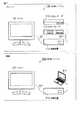
図1は、本発明の一実施形態に係わる、リビングにおよび書斎のそれぞれに設置されたHDMI(High-Definition Multimedia Interface)システムを示す概略図である。 FIG. 1 is a schematic diagram showing a high-definition multimedia interface (HDMI) system installed in each of a living room and a study according to an embodiment of the present invention.
先ず、リビングに設置されたHDMIシステム100について説明する。HDMIシステム100は、アンテナから地上デジタル放送波を受信し復調して表示、または外部入力から映像信号を受信して表示する電子機器であるテレビ1と、中継装置と、DVD等のメディアを再生するDVDプレーヤ111と、放送および外部入力からの映像信号を記録し、記録したコンテンツを外部に出力可能なHDD(Hard Disk Drive)レコーダ122とを有する。 First, the
テレビと中継装置とがHDMIケーブルによって接続されている。中継装置とDVDプレーヤとがHDMIケーブルによって接続されている。中継装置とHDDレコーダとがHDMIケーブルによって接続されている。HDMIケーブルは、HDMI規格に基づいて映像信号および音声信号の伝送に用いられる。また、HDMIケーブル内には、CEC規格に準拠した信号を伝送するためのCECラインが設けられている。CEC規格は、HDMI端子にある1本の端子(CEC端子)を介して、HDMI接続機器の制御を相互に行うことができるシリアル通信プロトコルである。 The television and the relay device are connected by an HDMI cable. The relay device and the DVD player are connected by an HDMI cable. The relay device and the HDD recorder are connected by an HDMI cable. The HDMI cable is used for transmission of video signals and audio signals based on the HDMI standard. Further, a CEC line for transmitting a signal compliant with the CEC standard is provided in the HDMI cable. The CEC standard is a serial communication protocol that enables mutual control of HDMI connected devices via one terminal (CEC terminal) in the HDMI terminal.
テレビ101は、HDMIケーブル121で接続された各電子機器との接続を、テレビ101の電源投入時に確認するほか、通常動作中に定期的に確認する。接続確認の情報の送受信はHDMIケーブル内のコマンド線を用いて行う。 The
次に、居間に設置されたHDMIシステム200について説明する。HDMIシステム200は、アンテナから地上デジタル放送波を受信し復調して表示、または外部入力から映像信号を受信して表示する電子機器であるテレビ1と、中継装置と、DVD等のメディアを再生が再生可能、且つ放送および外部入力からの映像信号を記録し、記録したコンテンツを外部に出力可能なパーソナルコンピュータ211とを有する。それぞれを図示するようにHDMIケーブル221で接続することで構成される。 Next, the HDMI system 200 installed in the living room will be described. The HDMI system 200 reproduces media such as the television 1, which is an electronic device that receives and displays a digital terrestrial broadcast wave from an antenna, demodulates and displays it, or receives and displays a video signal from an external input, a relay device, and a DVD. A
図2は、本発明の一実施形態に係わるHDMIシステム構成の一例を示すブロック図である。
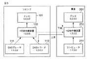
本システム構成では、リビングと書斎にそれぞれテレビが一台づつありHDMI中継装置を経由してDVDプレーヤ111,DVDレコーダ112,ノートブック型パーソナルコンピュータ211などのHDMI機器と接続されている。リビングと書斎のそれぞれのHDMI経路はHDMI中継装置を介して、無線接続などで相互に接続されている。なお本実施形態ではHDMI中継装置間は無線で接続されているが、有線の接続を用いてもよい。FIG. 2 is a block diagram showing an example of an HDMI system configuration according to an embodiment of the present invention.
In this system configuration, one TV is provided in each of the living room and the study, and is connected to HDMI devices such as a
図3は、HDMI中継装置の上流および下流の概念について説明する図である。 FIG. 3 is a diagram illustrating the upstream and downstream concepts of the HDMI relay device.
HDMIは映像ストリームの伝送に方向性があり、DVDプレーヤなどのソース機器のHDMI出力から、TV(シンク機器)のHDMI入力まで映像ストリームが流れる。このとき映像ストリームの流れを、川の流れにたとえて、HDMI中継装置からみて、映像ストリームが流れ込む側を下流、映像ストリームが流れ出す側を上流と呼ぶ。 HDMI has directionality in transmission of a video stream, and a video stream flows from an HDMI output of a source device such as a DVD player to an HDMI input of a TV (sink device). At this time, the flow of the video stream is compared to the flow of the river, and when viewed from the HDMI relay apparatus, the side on which the video stream flows is called downstream, and the side on which the video stream flows is called upstream.
図4は、中継区間を経由してストリームを受信する場合におけるHDMI中継装置の上流および下流の概念について説明する図である。中継経路は双方伝送が可能であり、図4の例ではNote PCからリビングTVまで映像ストリームが流れている。この場合、映像ストリームが流れ込む中継経路側を上流、TVへ流れ出すHDMI経路側を下流と呼ぶ。 FIG. 4 is a diagram for explaining the concept of upstream and downstream of the HDMI relay apparatus when a stream is received via the relay section. Both transmissions are possible on the relay path, and in the example of FIG. 4, a video stream flows from the Note PC to the living TV. In this case, the relay path side into which the video stream flows is referred to as upstream, and the HDMI path side to flow out to the TV is referred to as downstream.
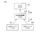
図5は、中継区間を経由してストリームを送信する場合におけるHDMI中継装置の上流および下流の概念について説明する図である。中継経路は双方伝送が可能であり、図5の例ではDVD Playerから書斎TVまで映像ストリームが流れている。この場合、映像ストリームが流れ込むHDMI経路側を上流、映像ストリームが流れ出すHDMI経路側を下流と呼ぶ。 FIG. 5 is a diagram for explaining the concept of upstream and downstream of the HDMI relay apparatus when a stream is transmitted via a relay section. The relay path can be transmitted in both directions, and in the example of FIG. 5, a video stream flows from the DVD player to the study TV. In this case, the HDMI path side on which the video stream flows is called upstream, and the HDMI path side on which the video stream flows is called downstream.
図6は、図2に示す本実施形態のシステム構成において、それぞれのTVを基準にした物理アドレスの違いを説明する図である。 FIG. 6 is a diagram for explaining a difference in physical address based on each TV in the system configuration of the present embodiment shown in FIG.
物理アドレスは、0.0.0.0の物理アドレスをもつTVを起点として、TVからの接続の段数(物理アドレスの桁数)と各接続の端子番号により表される。例えば図2のリビングTVを基準にした場合、リビングTVのHDMI入力1に接続されたHDMI中継装置の物理アドレスは、1桁目を1にして1.0.0.0、同様にHDMI中継装置のHDMI入力2に接続されたDVD Recorderの物理アドレスは、HDMI中継装置のアドレスからさらに2桁目を2にして1.2.0.0のように表す。このように物理アドレスはTVのアドレス0.0.0.0を起点として設定されるため、図2のように複数のTVがHDMI中継装置を経由して接続されている場合、リビングTVを起点に設定したDVD Recorderの物理アドレス(1.2.0.0)と書斎TVを基点に設定したDVD Recorderの物理アドレス(1.2.2.0)は異なる値を示すこととなり、リビングTVもしくは書斎TVから物理アドレスを用いて正しく映像ストリームの伝送制御(経路制御)を行うためには、HDMI中継装置間で正しくアドレス変換を行う必要がある。 The physical address is represented by the number of stages of connection from the TV (the number of digits of the physical address) and the terminal number of each connection starting from the TV having the physical address of 0.0.0.0. For example, when the living TV shown in FIG. 2 is used as a reference, the physical address of the HDMI relay apparatus connected to the HDMI input 1 of the living TV is 1.0.0.0 with the first digit being 1, and similarly the HDMI relay apparatus. The physical address of the DVD Recorder connected to the HDMI input 2 is expressed as 1.2.0.0 by setting the second digit to 2 from the address of the HDMI relay device. Thus, since the physical address is set starting from the TV address 0.0.0.0, when a plurality of TVs are connected via the HDMI relay device as shown in FIG. 2, the living TV is the starting point. The physical address (1.2.0.0) of the DVD Recorder set to 1 and the physical address (1.2.2.0) of the DVD Recorder set based on the study TV show different values. In order to correctly perform video stream transmission control (path control) using the physical address from the study TV, it is necessary to correctly perform address conversion between HDMI relay apparatuses.
図7は、本発明の一実施形態に係わるHDMI中継装置の概略を示すブロック図である。
HDMI中継装置110,210は、HDMI入力1、HDMI入力2、HDMI入力3を有する。HDMI入力1は、アドレス線301、およびコマンド線311等を有する。HDMI入力2は、アドレス線302、およびコマンド線312等を有する。HDMI入力3は、アドレス線303、およびコマンド線313等を有する。FIG. 7 is a block diagram showing an outline of an HDMI relay apparatus according to an embodiment of the present invention.
The
なお、図7ではHDMI入力端子が3端子の例を示していあるが、この端子数は3以外の数でも構わない。 Although FIG. 7 shows an example in which the HDMI input terminal is three terminals, the number of terminals may be other than three.
また、HDMI中継装置110,210は、EDID(Extended Display Identification Data)321、EDID322、EDID323等を有する。EDID321には、HDMI入力1のアドレス線301が接続されている。EDID322には、HDMI入力2のアドレス線302が接続されている。EDID323には、HDMI入力3のアドレス線303が接続されている。各EDID321〜323には、HDMI入力に接続されたソース機器が使うべき物理アドレスが記述されている。 Also, the
また、HDMI中継装置110,210は、HDMIスイッチ部330、HDMI受信部331、HDMI送信部332、スイッチ制御部334、CECコマンド制御部335、コマンド処理部336、AVCコマンド制御部337、アドレス管理部338、映像転送部339、無線MAC(Media Access Control)部340、無線PHY(PHYsical)部341等を有する。 The
HDMIスイッチ部330は、各HDMI入力端子1〜3から入力される映像ストリームの一本を選択して、HDMI受信部331に伝送する。HDMI受信部331では、伝送された映像ストリームに対して受信のための処理を実行し、処理後の信号を映像伝送部339に送る。HDMI受信部331で行われる処理の例としては、暗号化された映像ストリームの復号処理や映像ストリーム中のメタデータ取得処理などがある。 The
映像伝送部339は、受信した信号を無線MAC部340、或いはHDMI送信部332に送信する。無線MAC部340は、無線PHY部341から送信されるパケットの送出時点及び送出順序を決定する。無線PHY部341は、無線PHY部341で送出時点および送出順序に従って、接続先のHDMI中継装置に送信する。一方、接続先のHDMI中継装置より伝送された映像ストリームは、無線PHY部341および無線MAC部340により受信され、映像伝送部を経由してHDMI送信部332に転送される。 The
HDMI出力のアドレス線を経由して下流の機器より取得した物理アドレス情報は、HDMI送信部332を経由してアドレス管理部338で受け取るとともに、アドレス処理を施されたあとEDID1〜3にそれぞれ設定される。アドレス管理部338では、HDMI中継装置間の接続の端子番号をHDMI入力端子数+1とする。アドレス処理の具体例はHDMI Specification 1.3a(「High-Definition Multimedia Interface Specification Version 1.3a」 Hitachi, Ltd./Matsushita Electric Industrial Co. , Ltd. / Philips Consumer Electronics, International B.V./Silicon Image, Inc. / Sony Corporation /Thomson Inc. /Toshiba Corporation November 10,2006)に詳しい記載がある。 The physical address information acquired from the downstream device via the HDMI output address line is received by the
HDMI入力1〜3もしくはHDMI出力より受信したCECコマンドは、コマンド線311〜314を経由して、CECコマンド制御部335に渡される。CECコマンドの内容はコマンド処理部336に渡り、適切な処理が行われる。 The CEC command received from the HDMI inputs 1 to 3 or the HDMI output is passed to the CEC
一方無線PHY部341および無線MAC部340経由で受信したコマンドは、AVCコマンド制御部337を経由して同様にコマンド処理部336に渡される。コマンド処理部336はCECコマンド制御部335やAVCコマンド制御部337経由で受信したコマンドの内容に応じて適切な処理を行い、アドレス管理部338やHDMIスイッチ部330に指示を出したり、CECコマンド制御部335やAVCコマンド制御部337を経由して、コマンド送信などの処理を行う。 On the other hand, the command received via the
なお本ブロックでは、無線MAC部340および無線PHY部341を搭載しているが、この部分を有線伝送部で置き換えるなど別の接続部を設けてもよい。 In this block, the
図8は、本発明の一実施形態に係わるHDMI中継機器の物理アドレス通知方法を示すフローチャートである。なお、リビングのHDMIシステム100が稼働している状態で、書斎のHDMIシステムが稼働させた場合について説明する。 FIG. 8 is a flowchart showing a physical address notification method for an HDMI relay device according to an embodiment of the present invention. A case where the study HDMI system is operated while the living
先ず、HDMI中継装置210のアドレス管理部338は、HDMIケーブル経由で下流の機器であるテレビ201のEDIDから、自己の物理アドレスを取得する(ステップS11)。本実施形態の場合、HDMI中継装置210のアドレス管理部338は自己の物理アドレスとして(1.0.0.0)を取得する。 First, the
HDMI中継装置210のアドレス管理部338は、取得した物理アドレスの有効範囲の次の桁に、中継経路の端子番号を割り当てて、接続先のHDMI中継装置110の物理アドレスを生成する(ステップS12)。本実施形態の場合、有効範囲が上位1桁目であるので、2桁目に中継経路の端子番号を割り当て、接続先のHDMI中継装置110の物理アドレスとして(1.2.0.0)を生成する。 The
HDMI中継装置210のアドレス管理部338は、生成した物理アドレス(1.2.0.0)をHDMI中継装置110に通知する(ステップS13)。 The
同様に、HDMI中継装置110のアドレス管理部338は、既に割り当てられている物理アドレス(1.0.0.0)からHDMI中継装置210の物理アドレス(1.3.0.0)を生成し、HDMI中継装置210に通知する。 Similarly, the
図9は、本発明の一実施形態に係わる、物理アドレス変換に用いるHDMI中継装置のアドレス管理部のアドレス情報の伝達方法を示す図である。 FIG. 9 is a diagram illustrating a method of transmitting address information of the address management unit of the HDMI relay apparatus used for physical address conversion according to an embodiment of the present invention.
HDMI中継装置110のアドレス管理部338は、テレビ101を基準にしたHDMI中継装置210の物理アドレスをHDMI中継装置210に通知する。HDMI中継装置110のアドレス管理部338は、物理アドレスの設定ルールに従いHDMI中継装置110の物理アドレス(1.0.0.0)の2桁目を3で置き換えたアドレス(1.3.0.0)を、HDMI中継装置210のテレビ101を基準にした物理アドレスとしてHDMI中継装置210に通知する。 The
同様に、HDMI中継装置210のアドレス管理部338は、テレビ201を基準にしたHDMI中継装置110の物理アドレスをHDMI中継装置110に通知する。HDMI中継装置210からHDMI中継装置110を見た場合、HDMI中継装置間の接続の端子番号は設定ルールにより2と求まるので、HDMI中継装置210の物理アドレス(1.0.0.0)の2桁目を2に置き換えた物理アドレス(1.2.0.0)を、HDMI中継装置210を基準にしたHDMI中継装置110の物理アドレスとしてHDMI中継装置110に通知する。 Similarly, the
次に、図10および図11を参照して、コマンドの送信側のHDMI中継装置のアドレス管理部における物理アドレス変換処理方法を説明する。
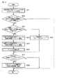
送信側のHDMI中継装置のアドレス管理部338が、HDMI経由で送信機器の物理アドレスを含むCECコマンドを受信する(ステップS21)。送信側のHDMI中継装置のアドレス管理部338は、ステップS21で受信したコマンドに含まれる送信機器の物理アドレスに該当する機器は自機器の上流の機器であるか否かを判別する(ステップS22)。Next, a physical address conversion processing method in the address management unit of the HDMI relay apparatus on the command transmission side will be described with reference to FIG. 10 and FIG.
The
例えば、図11に示すように、書斎のテレビ201に物理アドレス(2.0.0.0)を有するカムコーダ220が接続され、カムコーダ220が自己の物理アドレスをシンク装置に報告するための<Report Physical Address>コマンドを送信した場合を考える。HDMI中継装置210のアドレス管理部338は、<Report Physical Address>コマンドを受信した場合、HDMI中継装置110に転送するべきかを判断するために、<Report Physical Address>コマンドに含まれる物理アドレス(2.0.0.0)を有する機器(カムコーダ220)が自機器の上流の機器であるか否かを判別する。 For example, as shown in FIG. 11, a
例えば、図11に示すカムコーダ220のように、HDMI経由で受信したCECコマンドに含まれる物理アドレス(2.0.0.0)が、HDMI中継装置110からみて、HDMI側の上流でも、中継経路側の上流のいずれでもない場合、受信したCECコマンドの転送は不要と判断し、アドレス変換処理およびコマンド転送処理を行わないようにする。 For example, as in the
自機器の上流ではないと判断した場合(ステップS22のNO)、送信側のHDMI中継装置のアドレス管理部338は、コマンドを転送する必要がないので、処理を終了する。自機器の上流であると判断した場合(ステップS22のYES)、送信側のHDMI中継装置のアドレス管理部338は、ステップS21で受信した送信元の物理アドレスに該当する機器は同一HDMI経路上の機器であるか否かを判別する(ステップS23)。なお、同一HDMI経路上の機器とは、自己に割り当てられている物理アドレスの基準となったシンク装置を基準にした物理アドレスが割り当てられている機器のことである。 If it is determined that it is not upstream of the own device (NO in step S22), the
同一HDMI経路上の機器であると判断した場合(ステップS23のYES)、送信側のHDMI中継装置のアドレス管理部338は、同一HDMI経路上のシンク装置を基準にして自己に割り当てられている物理アドレスを変換元物理アドレスとして設定する(ステップS24)。 If it is determined that the devices are on the same HDMI path (YES in step S23), the
そして、送信側のHDMI中継装置のアドレス管理部338は、コマンドを転送するHDMI中継装置と同一HDMI経路上のシンク装置を帰順した物理アドレスを変換先物理アドレスとして設定する(ステップS25)。送信側のHDMI中継装置のアドレス管理部338は、アドレス変換処理ルーチンを呼び出し、アドレス変換処理を実行する(ステップS26)。 Then, the
また、ステップS23において、同一HDMI経路上の機器ではないと判断した場合(ステップS23のNO)、送信側のHDMI中継装置のアドレス管理部338は、HDMI中継装置210に転送するコマンドにアドレス変換を要求する情報を付加する(ステップS29)。本実施形態の場合、コマンドを送るヘッダにアドレス変換要求フラグを設け、アドレス変換要求フラグをイネーブルにする。 If it is determined in step S23 that the devices are not on the same HDMI path (NO in step S23), the
ステップS26またはステップS29の処理後、変換後の物理アドレスがF.F.F.Fであるか否かを判別する(ステップS27)。F.F.F.Fは無効なアドレスを表している。物理アドレスがF.F.F.Fではないと判断した場合(ステップS27のYES)、CECコマンドを接続先のHDMI中継装置に転送する(ステップS28)。物理アドレスがF.F.F.Fであると判断した場合(ステップS27のNO)、処理を終了する。 After the process of step S26 or step S29, the converted physical address is F.D. F. F. It is determined whether or not it is F (step S27). F. F. F. F represents an invalid address. Physical address is F. F. F. When it is determined that it is not F (YES in step S27), the CEC command is transferred to the connection destination HDMI relay apparatus (step S28). Physical address is F. F. F. If it is determined that it is F (NO in step S27), the process is terminated.
次に、ステップS26のアドレス変換処理について、図13および図14を参照して説明する。図12は、本発明の一実施形態におけるアドレス変換方法を示すフローチャートである。図13は、本発明の一実施形態におけるアドレス変換方法の説明に用いる図である。 Next, the address conversion process in step S26 will be described with reference to FIGS. FIG. 12 is a flowchart showing an address conversion method according to an embodiment of the present invention. FIG. 13 is a diagram used for explaining the address conversion method according to the embodiment of the present invention.
先ず、変換対象の物理アドレスから、変換元物理アドレスの有効範囲と共通部分を削除する(ステップS31)。削除後の物理アドレスを、変換先物理アドレスの有効範囲に接続する(ステップS32)。接続後の物理アドレスは5桁以上であるか否かを判別する(ステップS33)。 First, the effective range and common part of the conversion source physical address are deleted from the conversion target physical address (step S31). The physical address after deletion is connected to the effective range of the conversion destination physical address (step S32). It is determined whether the physical address after connection is 5 digits or more (step S33).
5桁以上であると判断した場合(ステップS33のYES)、5桁以降の物理アドレスが全て0であるか否かを判別する(ステップS34)。全て0であると判断した場合(ステップS34のYES)、5桁以降の0を削除する(ステップS35)。また、全て0ではないと判断した場合(ステップS34のNO)、4桁を全て16進数の“F”(10進数で15に相当に設定する。 When it is determined that the number is 5 digits or more (YES in step S33), it is determined whether or not the physical addresses after the 5th digit are all 0 (step S34). If it is determined that all are 0 (YES in step S34), 0 after the fifth digit is deleted (step S35). If it is determined that all are not 0 (NO in step S34), all four digits are set to hexadecimal "F" (decimal number 15).
ステップS33において、5桁以上ではないと判断した場合(ステップS33のNO)、接続語の物理アドレスが3桁以下であるか否かを判別する(ステップS37)。3桁であると判断した場合、4桁まで0を追加する(ステップS38)。3桁以下ではないと判断した場合、処理を終了する。 If it is determined in step S33 that the number is not 5 digits or more (NO in step S33), it is determined whether or not the physical address of the connection word is 3 digits or less (step S37). If it is determined that there are 3 digits, 0 is added up to 4 digits (step S38). If it is determined that it is not less than 3 digits, the process is terminated.
次に、図13のフローチャートを参照して転送コマンド受信側のHDMI中継装置のアドレス管理部における物理アドレス変換処理について説明する。図13は、本実施形態における転送コマンド受信側のHDMI中継装置のアドレス管理部における物理アドレス変換処理方法を示すフローチャートである。 Next, physical address conversion processing in the address management unit of the HDMI relay device on the transfer command receiving side will be described with reference to the flowchart of FIG. FIG. 13 is a flowchart showing a physical address conversion processing method in the address management unit of the HDMI relay device on the transfer command receiving side in this embodiment.
受信側のHDMI中継装置のアドレス管理部338は、送信側のHDMI中継装置との間の中継経路経由(本実施形態の場合は無線通信)でCECコマンドを受信する(ステップS41)。受信側のHDMI中継装置のアドレス管理部338は、CECコマンドのヘッダに含まれるアドレス変換要求フラグがイネーブルであるか否かを判別する(ステップS42)。イネーブルであると判断した場合(ステップS42のYES)、受信側のHDMI中継装置のアドレス管理部338は、送信側のHDMI中継装置の物理アドレスの基準となるシンク装置を基準にした自己の物理アドレスを変換元物理アドレスとして設定する(ステップS43)。また、受信側のHDMI中継装置のアドレス管理部338は、同一HDMI経路上のシンク装置を基準にした物理アドレスを変換先物理アドレスとして設定する(ステップS44)。受信側のHDMI中継装置のアドレス管理部338は、ステップS26と同様に、アドレス変換処理ルーチンを呼び出し、アドレス変換処理を実行する(ステップS45)。ステップS42においてイネーブルではないと判断した場合(ステップS42のNO)、或いはステップS45のアドレス変換処理後、変換後の物理アドレスがF.F.F.Fであるか否かを判別する(ステップS46)。F.F.F.Fではないと判断した場合(ステップS46のYES)、CECコマンドを接続先のHDMI経路に転送する(ステップS47)。F.F.F.Fであると判断した場合(ステップS46のNO)、処理を終了する。 The
次に、図14を参照して本発明の一実施形態に係わるアドレス変換処理の第1の例について説明する。図14は、本発明の一実施形態に係わるアドレス変換処理の第一の例を示す図である。 Next, a first example of address conversion processing according to an embodiment of the present invention will be described with reference to FIG. FIG. 14 is a diagram showing a first example of address conversion processing according to an embodiment of the present invention.
この例では、1.2.0.0の物理アドレスを持つDVDレコーダ112から<Report Physical Address>コマンドというCECコマンドを送信した例について示している。<Report Physical Address>コマンドは、パラメータとして、送信元の機器の物理アドレス情報を含む。<Report Physical Address>コマンドを受信したHDMI中継装置110のアドレス管理部338は、物理アドレスに該当する機器がHDMI中継装置のHDMI入力端子の上流に存在するか判定する(ステップS22)。本実施形態では、送信元であるDVD RecorderはHDMI中継装置110とHDMI接続され上流に位置するので、HDMI中継装置110でアドレス変換が必要と判定する(ステップS22のYES)。HDMI中継装置110のアドレス管理部338は、自身の物理アドレス1.0.0.0とHDMI中継装置210から取得した物理アドレス1.2.0.0を用いて、<Report Physical Address>コマンドのパラメータに含まれる物理アドレス(1.2.0.0)をテレビ201を基準にした物理アドレス(1.2.2.0)に変換する(ステップS24〜26)。HDMI中継装置110のアドレス管理部338は、変換した物理アドレスを含む<Report Physical Address>コマンドを、HDMI中継装置110からHDMI中継装置210に転送する。 In this example, a CEC command called <Report Physical Address> command is transmitted from the
次に、図15を参照して、アドレス変換方法の具体例を説明する。以下では、図14を参照して説明した、DVDレコーダ112が送信した<Report Physical Address>コマンドに含まれる物理アドレスをHDMI中継装置110が変換する例について説明する。 Next, a specific example of the address conversion method will be described with reference to FIG. Hereinafter, an example in which the
まずHDMI中継装置110自身の物理アドレス情報が少なくとも2つ必要となる。1つは下流のHDMI機器(テレビ101)のHDMI入力端子から取得した物理アドレス(1.0.0.0)、もう一方は中継経路の先にあるHDMI中継装置210から取得した物理アドレス(1.2.0.0)である。 First, at least two pieces of physical address information of the
図15の例において、HDMI中継装置110中継装置が<Report Physical Address>[1.2.0.0]コマンドを受信した際、このコマンドのパラメータに含まれる1.2.0.0が変換対象の物理アドレスとなる。変換対象の物理アドレスが、同一HDMI経路の機器から受信した場合、まずHDMI側に対応するHDMI中継装置110の物理アドレス(1.0.0.0)と変換対象の物理アドレス(1.2.0.0)との比較を行い、HDMI中継装置110の物理アドレスの有効範囲(1桁目の1)と一致する部分を変換対象の物理アドレスから削除する。その結果、変換対象の物理アドレスは2.0.0の部分が残る。次に削除した物理アドレスを、テレビ201を基準にしたHDMI中継装置110の物理アドレス(1.2.0.0)の有効範囲(1.2)と結合する。その結果、変換対象の物理アドレスは1.2.2.0.0となる。最後にアドレスの桁数を確認し4桁以上の場合、4桁目以降の0を削除する。その結果最終的な変換後の物理アドレスは1.2.2.0となる。最後の桁数確認において、桁数調整前の物理アドレスが3桁以下(1.3.0など)の場合、4桁になるまで末尾に0を追加する(1.3.0.0)。桁数調整前にちょうど4桁の場合、調整処理は行わない。なお桁数が5桁以上あり、かつ5桁目以降に0以外の数値が含まれる場合(1.3.2.2.1など)、4桁すべての値が16進数のF(10進数で15)となるよう調整し、F.F.F.Fというアドレスに変換する。F.F.F.Fは無効なアドレスを表し、以後転送などの処理は行わないようにする。図14の例では同一HDMI経路の機器が送信したCECコマンドの変換だったため、テレビ101を基準にしたのHDMI中継装置110の物理アドレス(1.0.0.0)を変換元アドレス、テレビ201を基準にしたHDMI中継装置110自身の物理アドレス(1.2.0.0)を変換先アドレスとした。 In the example of FIG. 15, when the
中継経路経由で受信したコマンドにアドレス変換要求フラグがあり、それに従い物理アドレス変換を行う場合、上述した説明とは逆にお、中継経路側のHDMI中継装置110自身の物理アドレス(1.2.0.0)を変換元アドレス、HDMI側のHDMI中継装置110の物理アドレス(1.0.0.0)を変換先アドレスとして用いる。 If the command received via the relay path has an address translation request flag and physical address translation is performed in accordance with the flag, the physical address (1.2. 0.0) is used as the conversion source address, and the physical address (1.0.0.0) of the
次に、図16を参照して本発明の一実施形態に係わるアドレス変換処理の第2の例について説明する。図16は、本発明の一実施形態に係わるアドレス変換処理の第2の例を示す図である。 Next, a second example of the address conversion process according to an embodiment of the present invention will be described with reference to FIG. FIG. 16 is a diagram showing a second example of the address conversion process according to the embodiment of the present invention.
この例では、書斎のテレビ201から<Set Stream Path>[1.2.2.0]というCECコマンドが送信された場合を示す。<Set Stream Path>コマンドにはパラメータとして、接続先の機器の物理アドレス情報が含まれている。本CECコマンドを受信したHDMI中継装置210のアドレス管理部338は、パラメータに含まれる物理アドレスに該当する機器(DVDレコーダ112)がHDMI中継装置210の上流に存在するか判定する(ステップS22)。 In this example, a CEC command <Set Stream Path> [1.2.2.0] is transmitted from the
図16に示す例では、パラメータに含まれる物理アドレスに該当する機器(DVDレコーダ112)は、中継経路を介してHDMI中継装置210の上流に存在する。従って、HDMI中継装置210のアドレス管理部338は、パラメータに含まれる物理アドレスに該当する機器(DVDレコーダ112)は上流の機器であると判断する(ステップS22のYES)。 In the example illustrated in FIG. 16, the device (DVD recorder 112) corresponding to the physical address included in the parameter exists upstream of the
次に、HDMI中継装置210のアドレス管理部338は、パラメータに含まれる物理アドレスに該当する機器(DVDレコーダ112)は同一HDMI経路上の機器であるか否かを判別する(ステップS23)。図16に示す例では、パラメータに含まれる物理アドレスに該当する機器は、HDMI中継装置210とは同一HDMI経路上にはない。従って、HDMI中継装置210のアドレス管理部338は、パラメータに含まれる物理アドレスに該当する機器は、同一HDMI経路上にはないと判断する(ステップS23のNO)。 Next, the
そこでHDMI中継装置210のアドレス管理部338はアドレス変換は行わず、CECコマンドのヘッダに含まれるアドレス変換要求フラグをイネーブルにして(ステップS29)、<Set Stream Path>コマンドをHDMI中継装置110に転送する(ステップS28)。 Therefore, the
HDMI中継装置110のアドレス管理部338はアドレス変換要求フラグがイネーブルにセットされていることを確認した後、物理アドレス1.2.2.0を1.2.0.0に変換する。その後HDMI中継装置110は変換後のアドレスをパラメータとして含む<Set Stream Path>コマンドをHDMIのコマンド線経由で送信する。 After confirming that the address conversion request flag is set to enable, the
本実施形態の中継装置によれば、複数のシンク機器(テレビ)が混在するHDMI経路を、無線などで中継した場合にも、正しく物理アドレス変換および経路制御を行い、映像ストリーム伝送を行うことができる。 According to the relay device of the present embodiment, even when an HDMI route in which a plurality of sink devices (televisions) are mixed is relayed wirelessly or the like, it is possible to correctly perform physical address conversion and route control and perform video stream transmission. it can.
なお、本発明は、上記実施形態そのままに限定されるものではなく、実施段階ではその要旨を逸脱しない範囲で構成要素を変形して具体化できる。また、上記実施形態に開示されている複数の構成要素の適宜な組み合せにより種々の発明を形成できる。例えば、実施形態に示される全構成要素から幾つかの構成要素を削除してもよい。更に、異なる実施形態に亘る構成要素を適宜組み合せてもよい。 Note that the present invention is not limited to the above-described embodiment as it is, and can be embodied by modifying the constituent elements without departing from the scope of the invention in the implementation stage. Further, various inventions can be formed by appropriately combining a plurality of constituent elements disclosed in the embodiment. For example, some components may be deleted from all the components shown in the embodiment. Furthermore, you may combine suitably the component covering different embodiment.
301〜303…アドレス線,311〜314…コマンド線,321〜323…EDID,330…HDMIスイッチ部,331…HDMI受信部,332…HDMI送信部,334…スイッチ制御部,335…CECコマンド制御部,336…コマンド処理部,337…AVCコマンド制御部,338…アドレス管理部,339…映像伝送部,340…無線MAC部,341…無線PHY部。 301-303 ... Address line, 311-314 ... Command line, 321-323 ... EDID, 330 ... HDMI switch unit, 331 ... HDMI reception unit, 332 ... HDMI transmission unit, 334 ... Switch control unit, 335 ... CEC command control unit 336: Command processing unit 337: AVC command control unit 338: Address management unit 339: Video transmission unit 340: Wireless MAC unit 341: Wireless PHY unit
Claims (5)
Translated fromJapanese第1のシンク装置を基準にして割り当てられる第1物理アドレスを取得する手段と、
前記第1のシンク装置又はソース装置のいずれかから送信された、パラメータに物理アドレスを含むコマンドを受信する受信手段と、
前記コマンドを前記他の中継装置に転送する場合に、前記パラメータの中の物理アドレスを、前記第1物理アドレスに基づいて前記他の中継装置越しに接続された第2のシンク装置を基準にした物理アドレスに変換するアドレス変換手段と
を備え、
前記通信手段は、前記変換された物理アドレスを含むコマンドを前記他の中継装置に送信すること
を特徴とする中継装置。Communication means for communicating with other relay devices;
Means for obtaining a first physical address assigned with reference to the first sink device;
Receiving means for receiving a command including a physical address as a parameter, transmitted from either the first sink device or the source device;
Thecase to forwardthe commandbefore Symbol another relay device, the physical address in the parameter, the second sink device connected to said another relay device over on the basis of the first physical address An address conversion means for converting the physical address to a reference,
The communication device transmits the command including the converted physical address to the other relay device.
を更に備え、
前記アドレス変換手段は、前記物理アドレスの変換を前記他の中継装置で行なわない場合に、前記コマンドに含まれる物理アドレスを変換すること
を特徴とする請求項1記載の中継装置。Means for determining whether or not the other relay device performs conversion of a physical address included in the command;
2. The relay apparatus according to claim 1, wherein the address translation unit translates a physical address included in the command when the physical address is not translated by the other relay apparatus.
前記アドレス変換手段は、前記第1物理アドレスおよび前記第2物理アドレスに基づいて、前記パラメータの中の物理アドレスを前記他の中継装置越しに接続された第2のシンク装置を基準にした物理アドレスに変換すること
を特徴とする請求項1に記載の中継装置。Means for obtaining a second physical address assigned with reference to the second sink device;
The address conversion unit is configured to make the physical address in theparameter based on the second physical device based on the first physical address and the second physical address based on the second sink device connected via the other relay device.The relay device according toclaim 1, wherein the relay device is converted into a relay device.
第1のシンク装置及びソース装置のいずれかから送信された、前記第1のシンク装置を基準にして割り当てられる物理アドレスをパラメータに含むコマンドを受信する受信手段と、
を備え、
前記通信手段は、前記コマンドを前記他の中継装置に転送する場合に、前記他の中継装置に、前記パラメータ中の物理アドレスの、前記他の中継装置越しに接続された第2のシンク装置を基準にした物理アドレスへの変換を要求する情報と共に前記コマンドを送信すること
を特徴とする中継装置。Communication means for communicating with other relay devices;
Receiving means for receiving a command transmitted from one of the first sink device and the source device and including as a parameter a physical address assigned with reference to the first sink device;
With
Said communication means, said commandif you transfer to the other relay device, the other relay device, the physical address in the parameter, the other second sink connected to the relay device over A relay device, wherein the command is transmitted together with information requesting conversion to a physical address based on the device.
を更に備え、
前記通信手段は、前記物理アドレスの変換を前記他の中継装置で行う場合であって、前記コマンドに含まれる物理アドレスの、前記他の中継装置越しに接続された前記第2のシンク装置を基準にした物理アドレスへの変換を要求する情報と共に前記コマンドを送信すること
を特徴とする請求項4記載の中継装置。Means for determining whether or not the other relay device performs conversion of a physical address included in the command;
The communication means is a case where the physical address conversion is performed by the other relay device, and the physical address included in the command is based on the second sink device connected through the other relay device. 5. The relay apparatus according to claim 4, wherein the command is transmitted together with information requesting conversion to a physical address.
Priority Applications (1)
| Application Number | Priority Date | Filing Date | Title |
|---|---|---|---|
| JP2009224296AJP4940279B2 (en) | 2009-09-29 | 2009-09-29 | Relay device |
Applications Claiming Priority (1)
| Application Number | Priority Date | Filing Date | Title |
|---|---|---|---|
| JP2009224296AJP4940279B2 (en) | 2009-09-29 | 2009-09-29 | Relay device |
Related Parent Applications (1)
| Application Number | Title | Priority Date | Filing Date |
|---|---|---|---|
| JP2008126081ADivisionJP4388125B2 (en) | 2008-05-13 | 2008-05-13 | Relay device and relay method |
Related Child Applications (1)
| Application Number | Title | Priority Date | Filing Date |
|---|---|---|---|
| JP2012034913ADivisionJP2012138933A (en) | 2012-02-21 | 2012-02-21 | Communication system |
Publications (2)
| Publication Number | Publication Date |
|---|---|
| JP2009303273A JP2009303273A (en) | 2009-12-24 |
| JP4940279B2true JP4940279B2 (en) | 2012-05-30 |
Family
ID=41549593
Family Applications (1)
| Application Number | Title | Priority Date | Filing Date |
|---|---|---|---|
| JP2009224296AActiveJP4940279B2 (en) | 2009-09-29 | 2009-09-29 | Relay device |
Country Status (1)
| Country | Link |
|---|---|
| JP (1) | JP4940279B2 (en) |
Families Citing this family (1)
| Publication number | Priority date | Publication date | Assignee | Title |
|---|---|---|---|---|
| JP2013005265A (en) | 2011-06-17 | 2013-01-07 | Sony Corp | Content reproducing device and content reproduction control method |
Family Cites Families (8)
| Publication number | Priority date | Publication date | Assignee | Title |
|---|---|---|---|---|
| JP3561107B2 (en)* | 1997-01-09 | 2004-09-02 | 株式会社東芝 | Network connection device |
| JP2004274608A (en)* | 2003-03-11 | 2004-09-30 | Sharp Corp | Communication equipment |
| EP1646227B1 (en)* | 2003-07-14 | 2016-08-31 | Panasonic Intellectual Property Management Co., Ltd. | Signal switching device, signal distribution device, display device, and signal transmission system |
| WO2007136038A1 (en)* | 2006-05-19 | 2007-11-29 | Panasonic Corporation | Logic address allocation method |
| JP4868225B2 (en)* | 2006-06-20 | 2012-02-01 | ソニー株式会社 | Information processing apparatus and method, and program |
| JP4822972B2 (en)* | 2006-07-28 | 2011-11-24 | シャープ株式会社 | Display device |
| JP2008153826A (en)* | 2006-12-15 | 2008-07-03 | Matsushita Electric Ind Co Ltd | Device identifier setting method and wireless transmission device |
| JP2008153974A (en)* | 2006-12-18 | 2008-07-03 | Canon Inc | Switch device and data relay method |
- 2009
- 2009-09-29JPJP2009224296Apatent/JP4940279B2/enactiveActive
Also Published As
| Publication number | Publication date |
|---|---|
| JP2009303273A (en) | 2009-12-24 |
Similar Documents
| Publication | Publication Date | Title |
|---|---|---|
| JP4388125B2 (en) | Relay device and relay method | |
| US9769520B2 (en) | Electronic equipment, control information transmission and reception methods having bidirectional communication using predetermined lines | |
| JP4251460B2 (en) | Display system and display device | |
| JP4844230B2 (en) | COMMUNICATION SYSTEM, TRANSMISSION DEVICE AND RECEPTION DEVICE, COMMUNICATION METHOD, AND PROGRAM | |
| JP5460530B2 (en) | Display system, display device, and relay device | |
| JP5079872B2 (en) | Wireless communication device | |
| JP5560282B2 (en) | Wireless transmission method, wireless transmission device, wireless transmission system, program, and integrated circuit | |
| JP2005057714A (en) | Transmission device and transmission method | |
| US8925020B2 (en) | Transmission system, reproduction device, transmission method, and program | |
| JP2009111738A (en) | Network conversion transmission control apparatus | |
| US20090046998A1 (en) | Video apparatus capable of changing video output mode of external video apparatus and control method thereof | |
| JP4940279B2 (en) | Relay device | |
| JPWO2014155621A1 (en) | COMMUNICATION DEVICE, COMMUNICATION METHOD, AND PROGRAM | |
| JP2012138933A (en) | Communication system | |
| JP4889610B2 (en) | Display device and display system | |
| JP2004328383A (en) | Device control system, device control method, controlled device, program, recording medium | |
| JP4920112B2 (en) | Signal output device and signal output method | |
| JP4663601B2 (en) | Digital signal transmitting apparatus and digital signal transmitting method | |
| JP2009118528A (en) | Digital signal transmission method | |
| JP2005223644A (en) | Data receiver, data control device and data control system |
Legal Events
| Date | Code | Title | Description |
|---|---|---|---|
| A621 | Written request for application examination | Free format text:JAPANESE INTERMEDIATE CODE: A621 Effective date:20090929 | |
| A977 | Report on retrieval | Free format text:JAPANESE INTERMEDIATE CODE: A971007 Effective date:20110909 | |
| A131 | Notification of reasons for refusal | Free format text:JAPANESE INTERMEDIATE CODE: A131 Effective date:20111108 | |
| A521 | Written amendment | Free format text:JAPANESE INTERMEDIATE CODE: A523 Effective date:20120110 | |
| TRDD | Decision of grant or rejection written | ||
| A01 | Written decision to grant a patent or to grant a registration (utility model) | Free format text:JAPANESE INTERMEDIATE CODE: A01 Effective date:20120131 | |
| A01 | Written decision to grant a patent or to grant a registration (utility model) | Free format text:JAPANESE INTERMEDIATE CODE: A01 | |
| A61 | First payment of annual fees (during grant procedure) | Free format text:JAPANESE INTERMEDIATE CODE: A61 Effective date:20120227 | |
| FPAY | Renewal fee payment (event date is renewal date of database) | Free format text:PAYMENT UNTIL: 20150302 Year of fee payment:3 | |
| R151 | Written notification of patent or utility model registration | Ref document number:4940279 Country of ref document:JP Free format text:JAPANESE INTERMEDIATE CODE: R151 | |
| FPAY | Renewal fee payment (event date is renewal date of database) | Free format text:PAYMENT UNTIL: 20150302 Year of fee payment:3 |