JP4940029B2 - Continuous panel wall structure - Google Patents
Continuous panel wall structureDownload PDFInfo
- Publication number
- JP4940029B2 JP4940029B2JP2007166068AJP2007166068AJP4940029B2JP 4940029 B2JP4940029 B2JP 4940029B2JP 2007166068 AJP2007166068 AJP 2007166068AJP 2007166068 AJP2007166068 AJP 2007166068AJP 4940029 B2JP4940029 B2JP 4940029B2
- Authority
- JP
- Japan
- Prior art keywords
- panel
- wall
- members
- continuous
- connecting member
- Prior art date
- Legal status (The legal status is an assumption and is not a legal conclusion. Google has not performed a legal analysis and makes no representation as to the accuracy of the status listed.)
- Expired - Fee Related
Links
Images


Landscapes
- Load-Bearing And Curtain Walls (AREA)
Description
Translated fromJapanese本発明は、連結部材を用いてパネル部材を連設して天井面と床面とで固定させた連設パネル壁構造および自立型の連設仕切り壁に関するものである。The present invention relates to a continuous panel wall structure in which panel members are connected using a connecting member and fixed on a ceiling surface and a floor surface,and a self-standing continuous partition wall .
この種の連設パネル壁の簡易な構造として、例えば特許文献1には、横断面形状がH形の連結部材によって、複数のパネル部材を連設させるようにしたパネル連結構造が開示されている。 As a simple structure of this type of continuous panel wall, for example,
この文献に記載されている連結部材は、ウェブ片とフランジ片とによって両側部にパネル挿入部が形成され、そのパネル挿入部にパネル部材を挿入して、隣り合うパネルを連結できるようにしている。
ところで、事務所や住宅などでは、壁や柱には、時計や連絡ボード、額縁、日用品などが、フックなどを使用して吊り下げ、掛け止めされることが一般的に行われており、特に近年では、壁掛けテレビや壁掛け棚などの重量のあるものも壁付けされるようになっている。 By the way, in offices and homes, clocks, contact boards, picture frames, daily necessities, etc. are generally suspended and hooked on walls and pillars using hooks, etc. In recent years, heavy items such as wall-mounted televisions and wall-mounted shelves have also been walled.
このように、種々の物を壁や柱に取り付ける場合、従来では、住居者が必要に応じて、所望の箇所に、壁や柱にネジや釘、その他掛止部材で対応することが一般的である。 As described above, when attaching various objects to walls and pillars, conventionally, it is common for a resident to respond to a desired location with screws, nails, or other retaining members as required. It is.
しかしながら、上記のような壁掛けテレビや壁掛け棚などを設ける場合には、壁構造を十分に調べたうえで、それらの重量に十分に耐え得るように固定しなければならないため、住居者が簡易には取り付けることはできない。 However, when installing a wall-mounted TV or wall shelf as described above, the wall structure must be carefully examined and fixed so that it can sufficiently withstand the weight of the wall. Cannot be installed.
本発明は、このような事情を考慮して提案されたもので、住居者などが壁掛けテレビや壁掛け棚などを簡易に壁付けできる連設パネル壁構造および自立型の連設仕切り壁を提供することにある。The present invention has been proposed in view of such circumstances, and provides acontinuous panel wall structureand a self-supporting continuous partition wall that allows a resident or the like to easily attach a wall-mounted television, a wall shelf, or the like. There is.
なお、上記特許文献には、上述するように、簡易なパネル連結構造が記載されているが、物を壁に掛止させる構造については、特に提案されていない。 In addition, although the simple panel connection structure is described in the said patent document as mentioned above, especially the structure which latches an object on a wall is not proposed.
上記目的を達成するために、請求項1に記載の連設パネル壁構造は、パネル部材を連結部材を介在させて連設し、天井面と床面とで固定させて連続した壁を形成させるようにした連設パネル壁構造であって、連結部材は、上下にわたる中空部を有した構造とされ、両側端部にパネル部材を連結させる嵌合連結部を形成するとともに、前面、後面の少なくとも一方には上記中空部に通じる複数の掛止穴を形成した支柱構造となっており、連結部材の複数の掛止穴を設けた面の下端に、複数の掛止穴と連通する下端開口が形成されており、電化製品のコードを掛止穴に挿入し、中空部を通し、下端開口より取り出せるようになっている。In order to achieve the above object, the continuous panel wall structure according to
請求項2では、請求項1において、連結部材は、連設すべきパネル部材のそれぞれの側端部を突合せ方向に嵌入させる連結縦溝を嵌合連結部として有している。 According to a second aspect of the present invention, in the first aspect of the present invention, the connecting member has a connecting longitudinal groove for fitting each side end portion of the panel member to be connected in the butting direction as a fitting connecting portion.
請求項3に記載の自立型の連設仕切り壁は、請求項1または2に記載の連結部材を少なくとも一組用いて、3枚以上のパネル部材を連結し、連結部材に棚板を架け渡すとともに、パネル部材を天井面と床面とに固定した構造としている。 The self-standing continuous partition wall according to
(削除) (Delete)
請求項1に記載の連設パネル壁構造によれば、パネル部材を連設するための連結部材は、両側端部にパネル部材を連結させる嵌合連結部を形成し、かつ前後面の少なくとも一方には複数の掛止穴を形成した支柱構造となっているため、それらの掛止穴を使用して、種々の物を吊るしたり掛けたりすることができる。特に、パネル部材を挟んだ一組の連結部材の水平位置にある2つの掛止穴を使用すれば、壁掛けテレビや壁掛け棚などの重量があり所定の幅があるものでも、それらを一組の連結部材に架け渡すことで、所望の位置に容易に壁付けすることができる。 According to the continuous panel wall structure according to
また、連結部材が上下にわたる中空部を有し、掛止穴がその中空部に通じた構造であるため、その中空部に配線を通すことで壁に沿う配線を隠すことができる。 In addition, since the connecting member has a hollow portion extending vertically, and the latching hole communicates with the hollow portion, the wiring along the wall can be hidden by passing the wiring through the hollow portion.
さらに、連結部材の下端に、複数の掛止穴と連通する下端開口が形成されているため、高所に設けた電気器具の配線を低所のコンセントに接続する場合に、壁面に沿って縦に走る配線をほとんど露出させることなく、美観を損なわずに配線できる。 In addition, the lower end of the connecting member is formed with a lower end opening that communicates with a plurality of retaining holes. Therefore, when connecting the wiring of an electric appliance provided at a high place to a low-outlet outlet, Wiring can be done without losing aesthetics, with almost no exposed wiring.
請求項2に記載の連設パネル壁構造によれば、連結部材は嵌合連結部として、連設すべきパネル部材のそれぞれの側端部を突合せ方向に嵌入させる連結縦溝を有しているため、簡易な作業で、頑丈な連設パネル壁を構築できる。
請求項3に記載の自立型の連設仕切り壁によれば、請求項1または2に記載の連結部材を少なくとも一組用いて、3枚以上のパネル部材を連結し、連結部材に棚板を架け渡すとともに、パネル部材を天井面と床面とに固定した構造としているので、パネル部材の両面に物を掛け止めすることができ、そうすることでバランスもとれる。According to the continuous panel wall structure according to
According to the self-standing continuous partition wall according to
以下に、本発明の実施の形態について、添付図面を参照しながら説明する。 Embodiments of the present invention will be described below with reference to the accompanying drawings.
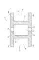
図1は、本発明の連設パネル壁構造の一例を模式的に示したもので、(a)は正面図、(b)は横断面図、(c)は右側面図である。 FIG. 1 schematically shows an example of a continuous panel wall structure according to the present invention, in which (a) is a front view, (b) is a cross-sectional view, and (c) is a right side view.
本例では、3枚のパネル部材1と、2個の連結部材2とを使用して連設パネル壁10を構成した例を示している。 In this example, an example in which the
3枚のパネル部材1は、連結部材2をパネル部材1間に介在させて連設されており、連設させた状態で、L字形の固定部材3を使用して、天井面Sと床面Fとに固定されている。 The three
図例では、固定部材3によって、連設パネル壁10の両側端に位置するパネル部材1、1の、連結部材2に連結されていない側端部11、11の上下端14、15と、各連結部材2、2の前後面22,23の上下端24、25との全12箇所を固定させている。このように、少なくとも両側のパネル部材1と全連結部材2について固定すれば、中央に位置する(連結部材2間に挟まれた)パネル部材1を固定しなくとも、連設パネル壁10を強固に固定できる。 In the illustrated example, the upper and
連結部材2は、その両側端(左右端)部21、21にパネル部材1を連結させるための嵌合連結部2aを形成した、中空の支柱構造となっており、前後面22,23のそれぞれに形成された複数の掛止穴2bと、前後面22、23のそれぞれの床面Fに接する下端に切欠き形成された下端開口2cとを有している。この下端開口2cは、中空部2d(図2参照)を介して複数の掛止穴2bと連通している。なお、中空部2dおよび連結部材2の他の詳細構造については、図2にて詳述する。 The connecting
図2は、連結部材2の横断面図である。 FIG. 2 is a cross-sectional view of the connecting
連結部材2は、アルミなどの金属または硬質樹脂などより製される中空の支柱であり、両側端部21、21には、2枚のパネル部材1の隣り合わせるべきそれぞれの側端部11、11を、突合せ方向に嵌入させる嵌合連結部2a、2aを備えている。この嵌合連結部2aは、連結部材2の腹部片2aaと、前後面22、23から側方側に突出した2つのフランジ片2ab、2abとより形成される、横断面視コ字形の嵌合凹所であり、上下にわたる、パネル部材1の連結用の縦溝として形成されている。The connecting
また中空部2dは、左右の腹部片2aa、2aaと、前後面22、23とによって囲まれた上下にわたる空間であり、適所に開設された掛止穴2bおよび下端開口2cを連通させている。このように、連結部材2は中空構造であるため、現場で切断して高さ調整が容易に行える。 The
なお本例では、連結部材2として中空部2dを有したものを示しているが、中実構造のものでもよい。その場合には、掛止穴は、後述するフック部材6(図5参照)を掛け止めできるような凹部が形成されていればよい。 In this example, the connecting
図3は、同連設パネル壁10の使用例を示す模式図で、(a)は正面図、(b)は横断面図である。 FIG. 3 is a schematic view showing an example of use of the
本例は、図1と同様、3枚のパネル部材1と2個の連結部材2とを使用した連設パネル壁10で、固定部材3を使用して天井面Sと床面Fとに固定されており、左右1組の連結部材2の前面側の水平位置にある1組の掛止穴2bに、壁掛けテレビ4を掛け止めしている。なお、壁掛けテレビ4の裏面の掛止穴2bに対応する位置には、フック部材6(図3では不図示)が固着されている。このフック部材6の掛止構造については、図5にて後述する。 In this example, as in FIG. 1, a
このように、3枚以上のパネル部材1を、2個以上の連結部材2を使用して連設したものでは、1組の連結部材2の対応する左右2箇所の掛止穴2bを使用できるので、壁掛けテレビ4など重量があり所定の幅を有したものでも、安定的に壁付けできる。壁掛けテレビ4の荷重は連結部材2にかかるが、2つに分散されて床に逃げるため、安定感がある。 Thus, in the case where three or
また、壁掛けテレビ4の配線は、先端にプラグ4bを接続したコード4aを、左右いずれか一方の連結部材2の掛止穴2bに挿入し、中空部2dを通し、下端開口2cより取り出すように配線しているため、壁に沿って縦に走る配線を連結部材2で隠すことができ、配線によって室内の美観が損なわれることを防止できる。 The wiring of the wall-mounted
このような中空構造は、壁掛けテレビ4に限らず、他の電化製品の配線にも使用でき、例えばエアコンなどの高所に設置するものでは、天井面近くにコンセントを特設しなくても、コードを連結部材2の中空部2dに隠して、床面に近い位置のコンセントに接続できる。また、中空部2dには、連結部材2に掛止しない電化製品の配線を通すこともできる。 Such a hollow structure can be used not only for the wall-mounted
また、中空構造であるため、連結部材2の前面22、後面23のいずれにも、掛止穴2bと下端開口2cを設けたものでは、壁掛けした面の掛止穴2bから挿入したコードを、反対側の面の下端開口2cより取り出して、反対側のコンセントに接続することができる。特に連設パネル壁10を間仕切りとして利用する場合、コンセントの位置によらず仕切ることができるので、利便性が高い。 Moreover, since it is a hollow structure, in the case where both the
さらに、連結部材2には下端開口2cが設けられているため、中空部2dの床面に溜まったホコリやゴミを取り出しやすい。 Furthermore, since the lower end opening 2c is provided in the connecting
図4は、同連設パネル壁10の他の使用例を示す模式図で、(a)は正面図、(b)は横断面図である。 FIG. 4 is a schematic view showing another example of use of the
本例も図1と同様、3枚のパネル部材1と2個の連結部材2とを使用した連設パネル壁10で、固定部材3を使用して天井面Sと床面Fとに固定されており、左右1組の連結部材2の前面の水平位置にある1組(2つ)の掛止穴2bを3段使用して、3枚の壁掛け棚5を掛け止めしている。なお、壁掛け棚5の壁側の側端5aの掛止穴2bに対応する位置には、上記壁掛けテレビ4の例と同様のフック部材6(図4では不図示)が固着されている。 As in FIG. 1, this example is a
このように、3枚以上のパネル部材1を、2個以上の連結部材2を使用して連設したものでは、1組の連結部材2の対応する左右2箇所の掛止穴2bを使用できるので、複数段の壁掛け棚5を架け渡して安定的に壁付けできる。例えば、台所用品棚、飾り棚、書棚などを簡易に設けることができる。なお、3個以上の連結部材2を使用する場合では、1枚の壁掛け棚5を、それら連結部材2の水平位置にある3箇所以上の掛止穴2bを使用して架け渡せば、さらに安定感が得られる。 Thus, in the case where three or
図5は、金属製のフック部材6の掛止構造の3例を示す斜視図で、(a)には図3,4で示した連結部材2に対応したものを示しており、(b)、(c)には他例の斜視図を示している。なお、図5(a)、(b)には、フック部材6の掛止部の部分斜視図を示している。 FIG. 5 is a perspective view showing three examples of the latching structure of the
図5(a)に示したフック部材6の掛止部は、連結部材2の掛止穴2bに掛止させる鉤片6aと、連結部材2の掛止穴2bより下方の垂直面より支持される被支持部6bとを有した構造とされる。 The hook portion of the
壁掛けテレビ4などに設けた1対のフック部材6の鉤片6aを、1組の連結部材2の掛止穴2bに引っ掛けることで、壁掛けテレビ4などを安定的に壁付けすることができる。 By hooking the
また図5(b)のフック部材6は、縦に並ぶ3つの鉤片6aを有しており、間隔を詰めて掛止穴を形成した連結部材に使用できる。3つの鉤片6aで掛け止めする構造であるため、さらに強固に壁付けできる。 The
図5(c)のフック部材6は、図5(a)と同様の形状の鉤片6aと、被支持部6bとを備え、さらに本体片6cの左右側に水平に突出させた棚固着片6dを有した構造となっている。なお、図中の6eは棚を固着させるためのネジ孔である。 The
このものでは、棚の左右端を、左右1組のフック部材6の対向する棚固着片6dに架け渡し、ネジ止めすることで、連結部材2間にパネル部材1の幅に応じた壁掛け棚を設けることができる。また、このフック部材6を使用すれば、使用するパネル部材1の枚数に応じて、同一形状、同一サイズの複数の壁掛け棚を左右方向に隙間なく連設することができる。なお、壁掛け棚のフック部材6の載置片6dへの固着は、かしめ接合によるものでもよい。 In this structure, the left and right ends of the shelf are bridged to the opposing
図6は、本発明の連設パネル壁構造を採用した自立型の連設仕切り壁による間仕切り例を示す間取図である。 FIG. 6 is a floor plan showing an example of partitioning by a self-standing continuous partition wall adopting the continuous panel wall structure of the present invention.
図例は、室内に仕切りのないリビングダイニングを、連設パネル壁10によって、一部に通路Pを設けるようにして、ダイニングキッチンDと、リビングLとに仕切った例を示している。連設パネル壁10は、インナー階段ISの室内側の側壁Wに直交するように固定され、ダイニングキッチンD側の連設パネル壁面には壁掛け棚5が取り付けられ、リビングL側の連設パネル壁面には壁掛けテレビ4が取り付けられている。 The figure shows an example in which a living dining room without a partition in a room is partitioned into a dining kitchen D and a living room L by providing a passage P in part by a
このように、本発明の連設パネル壁構造は簡易な室内リフォームなどで使用でき、完成した後は、住居者が壁掛けテレビ4や壁掛け棚5などを、所望の位置、高さに壁付けすることができる。また図例のように、両面に物を掛け止めすれば、バランスもとれる。 As described above, the continuous panel wall structure of the present invention can be used for simple indoor renovation and the like. After completion, the resident attaches the wall-mounted
以上の例では、連結部材2を1組(2個)使用して3枚のパネル部材1を連設させた連設パネル壁10を示しているが、3個以上使用してもよく、また1個の連結部材2を使用して、2枚のパネル部材1を連設させたものでもよい。1個の連結部材2を使用したものでも、縦に並ぶ掛止穴2bを使用して日用小物や額などを掛けたり吊り下げたりできる。 In the above example, one set (two) of the connecting
10 連設パネル壁、自立型の連設仕切り壁
1 パネル部材
11 側端(左右端)部
12 前面
13 後面
14 上端
15 下端
2 連結部材
21 側端部
22 前面
23 後面
24 上端
25 下端
2a 嵌合連結部(連結縦溝)
2aa 腹部片
2ab フランジ片
2b 掛止穴
2c 下端開口
2d 中空部
3 固定部材
4 壁掛けテレビ
5 壁掛け棚
6 フック部材
S 天井面
F 床面
DESCRIPTION OF
2aa Abdominal piece
Claims (3)
Translated fromJapanese上記連結部材は、上下にわたる中空部を有した構造とされ、両側端部にパネル部材を連結させる嵌合連結部を形成するとともに、前面、後面の少なくとも一方には上記中空部に通じる複数の掛止穴を形成した支柱構造となっており、
上記連結部材の上記複数の掛止穴を設けた面の下端に、上記複数の掛止穴と連通する下端開口が形成されており、電化製品のコードを上記掛止穴に挿入し、上記中空部を通し、上記下端開口より取り出せるようにしたことを特徴とする連設パネル壁構造。A panel panel wall structure in which a panel member is continuously provided with a connecting member interposed therebetween, and is fixed by a ceiling surface and a floor surface to form a continuous wall,
The connecting member has a structure having a hollow portion extending vertically, and forms a fitting connecting portion for connecting the panel member to both side end portions, and at least one of the front surface and the rear surface has a plurality of hooks that communicate with the hollow portion. It has a strut structure with a blind hole,
A lower end opening that communicates with the plurality of retaining holes is formed at the lower end of the surface of the connecting member on which the plurality of retaining holes are provided, anda cord of an electrical appliance is inserted into the retaining hole, and the hollow A continuous panel wall structure characterizedin that it can be taken out through the lower end opening .
上記連結部材は、連設すべきパネル部材のそれぞれの側端部を、突合せ方向に嵌入させる連結縦溝を嵌合連結部として有している連設パネル壁構造。In claim 1,
The connecting member has a connecting panel wall structure having connecting longitudinal grooves as fitting connecting portions for fitting the respective side end portions of the panel members to be provided in the butting direction.
Using at least one set of the connection members according to claim 1 or 2, three or more panel members are connected, a shelf board is bridged over the connection members, and the panel members are fixed to a ceiling surface and a floor surface. A self-standing continuous partition wall characterized by having a structured structure.
Priority Applications (1)
| Application Number | Priority Date | Filing Date | Title |
|---|---|---|---|
| JP2007166068AJP4940029B2 (en) | 2007-06-25 | 2007-06-25 | Continuous panel wall structure |
Applications Claiming Priority (1)
| Application Number | Priority Date | Filing Date | Title |
|---|---|---|---|
| JP2007166068AJP4940029B2 (en) | 2007-06-25 | 2007-06-25 | Continuous panel wall structure |
Publications (2)
| Publication Number | Publication Date |
|---|---|
| JP2009002100A JP2009002100A (en) | 2009-01-08 |
| JP4940029B2true JP4940029B2 (en) | 2012-05-30 |
Family
ID=40318778
Family Applications (1)
| Application Number | Title | Priority Date | Filing Date |
|---|---|---|---|
| JP2007166068AExpired - Fee RelatedJP4940029B2 (en) | 2007-06-25 | 2007-06-25 | Continuous panel wall structure |
Country Status (1)
| Country | Link |
|---|---|
| JP (1) | JP4940029B2 (en) |
Families Citing this family (3)
| Publication number | Priority date | Publication date | Assignee | Title |
|---|---|---|---|---|
| KR101166213B1 (en)* | 2012-01-17 | 2012-07-20 | 주식회사 엘제이테크 | Supporting device for security light being easy to install and maintenance |
| US8910580B1 (en)* | 2013-03-06 | 2014-12-16 | Stetforme Cockrell | Wall mount cabinet assembly |
| CN107218763A (en)* | 2017-04-28 | 2017-09-29 | 安徽豪迈机械科技有限公司 | A kind of suspension type refrigerator mounting bracket being easily installed |
Family Cites Families (2)
| Publication number | Priority date | Publication date | Assignee | Title |
|---|---|---|---|---|
| JPS51102798A (en)* | 1975-03-07 | 1976-09-10 | Hitachi Ltd | |
| JP2000087479A (en)* | 1998-09-10 | 2000-03-28 | Mitsuisa Ogata | Column for fixing partition wall and partition wall |
- 2007
- 2007-06-25JPJP2007166068Apatent/JP4940029B2/ennot_activeExpired - Fee Related
Also Published As
| Publication number | Publication date |
|---|---|
| JP2009002100A (en) | 2009-01-08 |
Similar Documents
| Publication | Publication Date | Title |
|---|---|---|
| US8365449B2 (en) | Configurable large-depth panel display | |
| US20080224579A1 (en) | Modular storage system | |
| US20080061018A1 (en) | Modular double-sided display panel | |
| US8887459B2 (en) | Modular wall assembly system | |
| JP4940029B2 (en) | Continuous panel wall structure | |
| US8407946B1 (en) | Closet liner | |
| US7784626B2 (en) | Wall hanging system | |
| EP1680976A1 (en) | Modular equipped wall | |
| CN1213954A (en) | storage device | |
| JP6749178B2 (en) | Hanging panel and smoke-proof hanging wall | |
| CN205053297U (en) | Suspension type multilayer partition plate for locker | |
| CN115551247A (en) | Expansion kit | |
| EP3498129B1 (en) | A furnishing item comprising a harness assembly integrated | |
| JP4067452B2 (en) | Free layout system for fixed objects using panels | |
| KR200451957Y1 (en) | Prefab shelves | |
| CN205338261U (en) | Locker interlayer | |
| JP4466381B2 (en) | Skirting skirting board for furniture | |
| KR20190131862A (en) | A sectional shelf capable of installing pipe hanger | |
| KR200191073Y1 (en) | Fixed structure of furniture | |
| JP3431017B2 (en) | Kitchen counter | |
| KR20110081508A (en) | Two way prefabricated lathe | |
| US20100077682A1 (en) | Screen opening for a drop ceiling | |
| JP2001061212A (en) | Structure for mounting wall socket and cabinet unit having structure for mounting wall socket | |
| KR0135588Y1 (en) | Angle for fixing bracket and panel | |
| JP2007307319A (en) | Multipurpose panel |
Legal Events
| Date | Code | Title | Description |
|---|---|---|---|
| A621 | Written request for application examination | Free format text:JAPANESE INTERMEDIATE CODE: A621 Effective date:20081222 | |
| A977 | Report on retrieval | Free format text:JAPANESE INTERMEDIATE CODE: A971007 Effective date:20110223 | |
| A131 | Notification of reasons for refusal | Free format text:JAPANESE INTERMEDIATE CODE: A131 Effective date:20110301 | |
| A521 | Written amendment | Free format text:JAPANESE INTERMEDIATE CODE: A523 Effective date:20110425 | |
| A131 | Notification of reasons for refusal | Free format text:JAPANESE INTERMEDIATE CODE: A131 Effective date:20110726 | |
| A521 | Written amendment | Free format text:JAPANESE INTERMEDIATE CODE: A523 Effective date:20110920 | |
| A711 | Notification of change in applicant | Free format text:JAPANESE INTERMEDIATE CODE: A712 Effective date:20120111 | |
| TRDD | Decision of grant or rejection written | ||
| A01 | Written decision to grant a patent or to grant a registration (utility model) | Free format text:JAPANESE INTERMEDIATE CODE: A01 Effective date:20120131 | |
| A01 | Written decision to grant a patent or to grant a registration (utility model) | Free format text:JAPANESE INTERMEDIATE CODE: A01 | |
| A61 | First payment of annual fees (during grant procedure) | Free format text:JAPANESE INTERMEDIATE CODE: A61 Effective date:20120227 | |
| FPAY | Renewal fee payment (event date is renewal date of database) | Free format text:PAYMENT UNTIL: 20150302 Year of fee payment:3 | |
| R150 | Certificate of patent or registration of utility model | Ref document number:4940029 Country of ref document:JP Free format text:JAPANESE INTERMEDIATE CODE: R150 Free format text:JAPANESE INTERMEDIATE CODE: R150 | |
| LAPS | Cancellation because of no payment of annual fees |