JP4939765B2 - Displacement measuring method and apparatus - Google Patents
Displacement measuring method and apparatusDownload PDFInfo
- Publication number
- JP4939765B2 JP4939765B2JP2005090460AJP2005090460AJP4939765B2JP 4939765 B2JP4939765 B2JP 4939765B2JP 2005090460 AJP2005090460 AJP 2005090460AJP 2005090460 AJP2005090460 AJP 2005090460AJP 4939765 B2JP4939765 B2JP 4939765B2
- Authority
- JP
- Japan
- Prior art keywords
- light
- polarization
- reflected
- polarization state
- interference
- Prior art date
- Legal status (The legal status is an assumption and is not a legal conclusion. Google has not performed a legal analysis and makes no representation as to the accuracy of the status listed.)
- Expired - Fee Related
Links
Images


Classifications
- G—PHYSICS
- G01—MEASURING; TESTING
- G01B—MEASURING LENGTH, THICKNESS OR SIMILAR LINEAR DIMENSIONS; MEASURING ANGLES; MEASURING AREAS; MEASURING IRREGULARITIES OF SURFACES OR CONTOURS
- G01B9/00—Measuring instruments characterised by the use of optical techniques
- G01B9/02—Interferometers
- G01B9/02055—Reduction or prevention of errors; Testing; Calibration
- G01B9/02056—Passive reduction of errors
- G01B9/02057—Passive reduction of errors by using common path configuration, i.e. reference and object path almost entirely overlapping
- G—PHYSICS
- G01—MEASURING; TESTING
- G01B—MEASURING LENGTH, THICKNESS OR SIMILAR LINEAR DIMENSIONS; MEASURING ANGLES; MEASURING AREAS; MEASURING IRREGULARITIES OF SURFACES OR CONTOURS
- G01B9/00—Measuring instruments characterised by the use of optical techniques
- G01B9/02—Interferometers
- G01B9/02001—Interferometers characterised by controlling or generating intrinsic radiation properties
- G01B9/02002—Interferometers characterised by controlling or generating intrinsic radiation properties using two or more frequencies
- G01B9/02003—Interferometers characterised by controlling or generating intrinsic radiation properties using two or more frequencies using beat frequencies
- G—PHYSICS
- G01—MEASURING; TESTING
- G01B—MEASURING LENGTH, THICKNESS OR SIMILAR LINEAR DIMENSIONS; MEASURING ANGLES; MEASURING AREAS; MEASURING IRREGULARITIES OF SURFACES OR CONTOURS
- G01B9/00—Measuring instruments characterised by the use of optical techniques
- G01B9/02—Interferometers
- G01B9/02055—Reduction or prevention of errors; Testing; Calibration
- G01B9/02075—Reduction or prevention of errors; Testing; Calibration of particular errors
- G01B9/02078—Caused by ambiguity
- G01B9/02079—Quadrature detection, i.e. detecting relatively phase-shifted signals
- G01B9/02081—Quadrature detection, i.e. detecting relatively phase-shifted signals simultaneous quadrature detection, e.g. by spatial phase shifting
- G—PHYSICS
- G03—PHOTOGRAPHY; CINEMATOGRAPHY; ANALOGOUS TECHNIQUES USING WAVES OTHER THAN OPTICAL WAVES; ELECTROGRAPHY; HOLOGRAPHY
- G03F—PHOTOMECHANICAL PRODUCTION OF TEXTURED OR PATTERNED SURFACES, e.g. FOR PRINTING, FOR PROCESSING OF SEMICONDUCTOR DEVICES; MATERIALS THEREFOR; ORIGINALS THEREFOR; APPARATUS SPECIALLY ADAPTED THEREFOR
- G03F7/00—Photomechanical, e.g. photolithographic, production of textured or patterned surfaces, e.g. printing surfaces; Materials therefor, e.g. comprising photoresists; Apparatus specially adapted therefor
- G03F7/70—Microphotolithographic exposure; Apparatus therefor
- G03F7/70691—Handling of masks or workpieces
- G03F7/70775—Position control, e.g. interferometers or encoders for determining the stage position
- G—PHYSICS
- G01—MEASURING; TESTING
- G01B—MEASURING LENGTH, THICKNESS OR SIMILAR LINEAR DIMENSIONS; MEASURING ANGLES; MEASURING AREAS; MEASURING IRREGULARITIES OF SURFACES OR CONTOURS
- G01B2290/00—Aspects of interferometers not specifically covered by any group under G01B9/02
- G01B2290/30—Grating as beam-splitter
- G—PHYSICS
- G01—MEASURING; TESTING
- G01B—MEASURING LENGTH, THICKNESS OR SIMILAR LINEAR DIMENSIONS; MEASURING ANGLES; MEASURING AREAS; MEASURING IRREGULARITIES OF SURFACES OR CONTOURS
- G01B2290/00—Aspects of interferometers not specifically covered by any group under G01B9/02
- G01B2290/70—Using polarization in the interferometer
Landscapes
- Physics & Mathematics (AREA)
- General Physics & Mathematics (AREA)
- Length Measuring Devices By Optical Means (AREA)
- Instruments For Measurement Of Length By Optical Means (AREA)
Description
Translated fromJapanese本発明は、光干渉を用いて対象物の変位を計測する方法とその装置に係り、特にレーザ光を対象物に照射し、その反射光を参照光と干渉させ、得られた干渉信号から対象物の変位量を計測する変位計測方法とその装置に関する。 The present invention relates to a method and apparatus for measuring the displacement of an object using optical interference, and in particular, irradiates the object with laser light, causes the reflected light to interfere with reference light, and uses the obtained interference signal as a target. The present invention relates to a displacement measuring method and apparatus for measuring the amount of displacement of an object.
対象物の変位量あるいは移動量を計測する方法として、光干渉を用いる方法が広く知られている(Meas. Sci. Technol., 9 (1998), 1024-1030)。その一例を図10に示す。 As a method for measuring the amount of displacement or movement of an object, a method using optical interference is widely known (Meas. Sci. Technol., 9 (1998), 1024-1030). An example is shown in FIG.
図10に示す干渉計において、レーザヘッド301からは、偏光方向が互いに直交し、かつ両者の光周波数が20MHz異なる2周波直交偏光ビーム302が出射される。このビームは偏光ビームスプリッタ303により、2つの偏光成分に分離される。S偏光ビーム303は偏光ビームスプリッタ303で反射された後、直角プリズム304で反射され、参照光として偏光ビームスプリッタ303に入射する。P偏光ビーム305は偏光ビームスプリッタ303を透過し、測定対象物400上に載置された直角プリズム306で反射され、偏光ビームスプリッタ303に入射する。両反射ビームは偏光ビームスプリッタ303で合成され、両反射ビームの偏光方向に対し45°方向に偏光角を有する偏光板307を透過後ヘテロダイン干渉する。 In the interferometer shown in FIG. 10, the
このヘテロダイン干渉光は光電変換素子308で受光され電気信号309に変換される。このヘテロダイン干渉信号309の周波数fMは、測定対象物400の移動速度Vに応じたドップラーシフト周波数が加わり、(数1)で与えられる。This heterodyne interference light is received by the
fM=fB±NV/λ ・・・ (数1)
ここで、fB=20MHzである。λはレーザ光の波長である。また、N=2、4、・・・で、光路の往復回数により決まる定数であり、図10の場合、N=2である。一方、レーザヘッド301からは、参照信号としてfB=20MHzのビート信号310が出力されている。fM = fB ± NV / λ (Equation 1)
Here, fB = 20 MHz. λ is the wavelength of the laser beam. Further, N = 2, 4,... Are constants determined by the number of reciprocations of the optical path, and in the case of FIG. 10, N = 2. On the other hand, a
測定されたヘテロダイン干渉信号309及び参照信号310は位相検出回路311に入力され、両信号間の位相差から測定対象物400の移動速度V及び移動量400dが求められ、移動量出力信号312として出力される。 The measured
図10に示す干渉計においては、プローブ光路、即ちプローブ光であるP偏光ビーム305が通過する光路と参照光であるS偏光ビーム303が通過する参照光路とが空間的に分離しているため、空気の揺らぎ等による温度分布や屈折率分布、あるいは機械振動が生じた場合、両光路間で光路差が変動し、これがナノメートルオーダの測定誤差となってしまう。将来の45nmノードや32nmノード対応の半導体微細パターン製造用露光装置やパターン寸法測定装置のステージ、あるいは局所的なキャラクタリゼーションに用いられるプローブ顕微鏡のプローブ位置制御にはサブナノメートルオーダ以下の位置決め精度が要求されており、図10に示す従来技術では、この要求に応えることができない。温度、湿度、機械振動といった環境要因を高精度に制御する方法も考えられうるが、装置コスト、装置サイズ、使い勝手の面で、経済的効果が著しく低下してしまう。 In the interferometer shown in FIG. 10, the probe optical path, that is, the optical path through which the P-polarized
本発明は、上記した課題を解決して、対象物の変位量や移動量を安定に計測可能な変位計測方法とその装置を提供するものである。 The present invention solves the above-described problems and provides a displacement measuring method and apparatus capable of stably measuring the amount of displacement and the amount of movement of an object.
本発明では、光源からの光を第1の光と第2の光に分離し、第1の光の光軸と第2の光の光軸とを近接させて第1の光を移動可能な対象物に照射し、第2の光を参照面に照射することにより、対象物からの反射光と参照面からの反射光とを干渉させてその干渉光から前記対象物の移動量を求める際に、外乱の影響を受けることなく高精度に対象物の移動量を求めることを可能にした。 In the present invention, the light from the light source is separated into the first light and the second light, and the first light can be moved by bringing the optical axis of the first light and the optical axis of the second light close to each other. When irradiating the object and irradiating the reference light with the second light, the reflected light from the object interferes with the reflected light from the reference surface, and the amount of movement of the object is obtained from the interference light In addition, the movement amount of the object can be obtained with high accuracy without being affected by disturbance.
また、本発明では、第1の光の光軸と第2の光の光軸とを近接させる際に、第1の光の光軸と第2の光の光軸の周囲の媒体の物性変化が第1の光の光軸と第2の光の光軸に等しく作用する距離として設定することにより、外乱の影響が2つの光に等しく作用して相殺させることとなり、外乱の影響を受けることなく高精度に対象物の移動量を求めることを可能にした。 In the present invention, when the optical axis of the first light and the optical axis of the second light are brought close to each other, the physical property change of the medium around the optical axis of the first light and the optical axis of the second light is changed. Is set as the distance that acts equally on the optical axis of the first light and the optical axis of the second light, the influence of the disturbance acts on the two lights equally to cancel each other, and is affected by the disturbance. The amount of movement of the object can be obtained with high accuracy.
また、本発明では、第1の光の光軸と第2の光の光軸とを近接させる際に、第1の光の光軸と第2の光の光軸とを一致させることにより、外乱の影響が2つの光に等しく作用して相殺させることとなり、外乱の影響を受けることなく高精度に対象物の移動量を求めることを可能にした。 In the present invention, when the optical axis of the first light and the optical axis of the second light are brought close to each other, by matching the optical axis of the first light and the optical axis of the second light, The influence of the disturbance acts on the two lights equally to cancel each other, making it possible to determine the amount of movement of the object with high accuracy without being affected by the disturbance.
また、本発明では、参照面を回折格子で構成することにより、第1の光の光軸と第2の光の光軸とを一致させることが可能となり、外乱の影響が2つの光に等しく作用し相殺されることとなり、外乱の影響を受けることなく高精度に対象物の移動量を求めることが可能となる。 Further, in the present invention, by configuring the reference surface with a diffraction grating, it is possible to make the optical axis of the first light coincide with the optical axis of the second light, and the influence of the disturbance is equal to the two lights. It acts and cancels out, and it becomes possible to determine the amount of movement of the object with high accuracy without being affected by disturbance.
また、本発明は、光源からの光を第1の光と第2の光に分離し、第1の光の光軸と第2の光の光軸とを近接させて第1の光を対象物の表面に照射し、第2の光を参照面に照射することにより、対象物の表面からの反射光と参照面からの反射光とを干渉させてその干渉光から前記対象物の表面の形状を求める際に、外乱の影響を受けることなく高精度に対象物の表面形状を求めることが可能となる。 In the present invention, the light from the light source is separated into the first light and the second light, and the optical axis of the first light and the optical axis of the second light are brought close to each other. By irradiating the surface of the object and irradiating the reference light with the second light, the reflected light from the surface of the object interferes with the reflected light from the reference surface, and the interference light reflects the surface of the object. When obtaining the shape, the surface shape of the object can be obtained with high accuracy without being affected by disturbance.
本発明によれば、空気の揺らぎ等による温度分布や屈折率分布あるいは機械振動といった外乱の影響が、プローブ光(第1の光)と参照光(第2の光)に等しく作用するので、2つの光が干渉した際に上記外乱の影響を相殺することが可能となる。この結果、空気揺らぎや機械振動といった外乱の影響を受けることなく、サブナノメートルオーダ以下の精度で干渉光から安定かつ高精度に対象物の変位量や移動量を求めることが可能となる。 According to the present invention, the influence of disturbance such as temperature distribution, refractive index distribution, or mechanical vibration due to air fluctuations acts on the probe light (first light) and the reference light (second light) equally. When two lights interfere with each other, it is possible to cancel the influence of the disturbance. As a result, it is possible to obtain the displacement amount and the movement amount of the target object from the interference light with accuracy of sub-nanometer order or less without being affected by disturbance such as air fluctuation and mechanical vibration.
また、上記共通光路形干渉計を構成することにより変位計測装置を小さくすることができ、測定対象物周辺のスペースが小さい場合にも本装置の適用が可能となる。 Further, by configuring the common optical path type interferometer, the displacement measuring device can be made small, and this device can be applied even when the space around the measurement object is small.
更に、温度、湿度、機械振動といった環境要因を高精度に制御する必要が無いため、装置コスト、装置サイズ、使い勝手の面で、経済的効果が著しく向上するという効果も有する。 Furthermore, since it is not necessary to control environmental factors such as temperature, humidity, and mechanical vibration with high accuracy, there is an effect that the economic effect is remarkably improved in terms of apparatus cost, apparatus size, and usability.
本発明の実施の形態を、図により説明する。 Embodiments of the present invention will be described with reference to the drawings.
本発明の第1の実施例を図1に基づいて説明する。本実施例の変位計測装置は、図1(a)に示すように、光源ユニット2、干渉計ユニット3及び位相検出ユニット18から成る。図1(b)に示すように、光源ユニット2においては、直線偏光レーザ光源21(例えば波長632.8nmの周波数安定化He−Neレーザ)からの直線偏光ビーム22を45°の偏光方向で偏光ビームスプリッタ23に入射させ、2つの偏光成分に分離する。P偏光ビーム24は偏光ビームスプリッタ23を透過し、周波数f1で駆動される音響光学変調素子25(AOM:Acousto−Optic Modulator)により、光周波数がf1だけシフトする。A first embodiment of the present invention will be described with reference to FIG. As shown in FIG. 1A, the displacement measuring apparatus according to the present embodiment includes a
一方、S偏光ビーム28は偏光ビームスプリッタ23で反射され、周波数f1+fBで駆動される音響光学変調素子29より、光周波数がf1+fBシフトする。ここで、fBは例えば100kHzから数10MHzである。P偏光ビーム24及びS偏光ビーム28は各々ミラー26及び26’で反射された後、偏光ビームスプリッタ27で合成された後、ミラー26”で反射されて、光源ユニット2から2周波直交偏光ビーム4として出射される。図1(c)中の24Pが2周波直交偏光ビーム4のP偏光ビーム24の偏光方向を、28SがS偏光ビーム28の偏光方向を示している。On the other hand, the S polarized
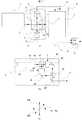
2周波直交偏光ビーム4は干渉計ユニット3に入射し、非偏光ビームスプリッタ5により、2つの光路に分離される。非偏光ビームスプリッタ5により反射された2周波直交偏光ビーム6は、図1(c)の破線7aで示すように両偏光方向に対し45°方向に偏光角を有する偏光板7を透過することによりヘテロダイン干渉する。このヘテロダイン干渉光はホトダイオード等の光電変換素子8で受光されビート周波数fBの電気信号9に変換され、参照信号として用いられる。一方、非偏光ビームスプリッタ5を透過した2周波直交偏光ビーム10は、参照ミラー11に入射する。参照ミラー11は、図2に示すように、合成石英基板11b上にAl等の金属材料で回折格子11gが形成された構成となっている。The two-frequency
このような回折格子は、図中に示すように、2周波直交偏光ビーム10のうち、回折格子の長手方向と平行なS偏光成分28Sは反射し、直交するP偏光成分24Pははそのまま透過する、いわゆる偏光素子(Wire Grid Polarizer)としての性質を示す。本実施例の場合、回折格子11gのピッチは144nm、線幅は65nm、高さは165nmとした。参照ミラー11で反射されたS偏光ビーム10rは参照光として用いる。透過したP偏光ビーム10mはプローブ光として用いる。 As shown in the figure, such a diffraction grating reflects the S-polarized
P偏光ビーム10mは1/4波長板12を透過した後円偏光となり、測定対象物1上に載置されたターゲットミラー13で反射され、再び1/4波長板12を透過後S偏光となり、参照ミラー11で反射され、1/4波長板12を透過後円偏光としてターゲットミラー13で反射され、1/4波長板12を透過後P偏光となり、参照ミラー11を透過する。即ち、プローブ光10mは参照ミラー11とターゲットミラー13との間の光路を2往復することになり、測定対象物1の移動量1dを2倍に拡大して検出することになる。 The P-polarized
参照ミラー11で反射されたS偏光ビーム10rと透過したP偏光ビーム10mは、2周波直交偏光ビーム14として非偏光ビームスプリッタ5で反射される。この2周波直交偏光ビーム14は、図1(c)の破線15aで示すように両偏光方向に対し45°方向に偏光角を有する偏光板15を透過することによりヘテロダイン干渉する。このヘテロダイン干渉光はホトダイオード等の光電変換素子16で受光され、電気信号17に変換される。このヘテロダイン干渉信号17の周波数fMは、測定対象物1の移動速度Vに応じたドップラーシフト周波数が加わり、(数1)で与えられる。The S-polarized beam 10 r reflected by the
(数1)において、N=4である。測定されたヘテロダイン干渉信号I(t)17及び光電変換素子8で得られた参照信号9は位相検出ユニット18に入力され、両信号間の位相差から測定対象物1の移動速度V及び移動量1dが求められ、移動量信号19として出力される。位相検出ユニット18は、例えばロックインアンプ等が使用可能である。ヘテロダイン干渉信号I(t)17は(数2)で与えられる。 In (Expression 1), N = 4. The measured heterodyne interference signal I (t) 17 and the reference signal 9 obtained by the photoelectric conversion element 8 are input to the
I(t)=Im+Ir
+2(Im・Ir)1/2cos(2πfBt±2πNVt/λ) ・・・ (数2)
ここで、Imはプローブ光の検出強度、Irは参照光の検出強度、nは空気の屈折率、λはレーザ光22の波長である。位相検出ユニット18からは、(数2)のcos成分の中の第2項:±2πNVt/λが位相信号として出力される。例えば、位相信号がπ/1800の場合、移動量1d=0.044nmとなる。I (t) = Im + Ir
+2 (Im · Ir )1/2 cos (2πfB t ± 2πNVt / λ) (Equation 2)
Here, Im detected intensity of the probe light, the detection intensity of Ir is the reference light, n is the refractive index of the air, lambda is the wavelength of the laser beam 22. The
図1から明らかなように、ターゲットミラー13に向かうプローブ光10mと参照光10rの2つのビームは、光源ユニット2から出射されて干渉計ユニット3に入射し、参照ミラー11に至るまで、更に参照ミラー11から光電変換素子16で受光されるに至るまで、完全に同一の光路を通る。即ち、共通光路形干渉計の構成となる。従って、仮に光路中に空気の揺らぎ等による温度分布や屈折率分布、あるいは機械振動が生じたとしても、これらの外乱は両ビームに等しく影響を及ぼすため、両ビームが干渉した際にこれら外乱の影響は完全に相殺され、干渉光は外乱の影響を受けない。唯一、参照ミラー11とターゲットミラー13との間の光路においてプローブ光10mのみが存在するが、例えば、プローブ顕微鏡等のストロークは高々数百ミクロン程度であるので、参照ミラー11とターゲットミラー13との間隙は1mm以下に設定することが可能であり、このような微小間隙での外乱の影響は無視できる。 As is clear from FIG. 1, the two beams of the
また、図1(b)に示す光源ユニット2では、直交する2つの偏光ビーム24、28が別光路を通る構成となっており、両光路間に外乱の影響が重畳する可能性がある。しかし、仮に外乱の影響がのったとしても、その影響は測定されたヘテロダイン干渉光と参照光の両方に等しくのるため、位相検出ユニット18において両者の位相差を検出する際に相殺される。 Further, in the
本実施例の干渉計の構成により、温度、湿度、音響振動といった環境因子を高精度に制御することなく、測定対象物1の移動速度V及び移動量1dをサブナノメートルからピコメートルの精度で安定に計測することが可能である。本実施例では、参照ミラーとして金属回折格子(Wire Grid Polarizer)を用いることにより、2周波直交偏光ビームのうち一方の偏光ビームからプローブ光を、他方の偏光ビームから参照光を同軸上に生成することが可能となり、共通光路形ヘテロダイン干渉計を構成することができるものである。 With the configuration of the interferometer of the present embodiment, the moving speed V and the moving
第1の実施例では、2周波直交偏光ビーム4を生成するために、図1(b)に示すように、2つの偏光ビームスプリッタ23、27と2つの音響光学変調素子25、29を用いたが、第2の実施例では、上記した第1の実施例において図1(b)に示した光源ユニット2の代わりに図3(a)に示すように、光源ユニット2’に2周波He−Neレーザ31(2本の縦モード発振を有するデュアルモードレーザ)を用いる。得られる2周波直交偏光ビーム32の偏光方向は、図3(b)中の32P及び32Sに示す通りであり、一例として640MHz程度のビート信号が得られる。干渉計ユニット3及び位相検出ユニット18の構成と機能は第1の実施例と同様であるので、説明を省略する。本実施例によれば、第1の実施例と同様、温度、湿度、音響振動といった環境因子を高精度に制御することなく、測定対象物1の移動速度V及び移動量1dをサブナノメートルからピコメートルの精度で安定に計測することが可能である。In the first embodiment, two
次に本発明の第3の実施例として、光源ユニット2から出射された2周波直交偏光ビーム4、32を偏波面保存ファイバにより干渉計ユニット3に伝送する変位計測装置について、図4により説明する。2周波直交偏光ビーム4、32は、偏光ビームスプリッタ41により、P偏光ビーム42とS偏光ビーム45に分離される。P偏光ビーム42は集光レンズ43により偏波面保存ファイバ44の入射端面44aに集光され、直線偏光を維持したまま伝送される。偏波面保存ファイバ44の出射端面44bから出射したP偏光ビームはコリメーティングレンズ46で平行ビームとなり、偏光ビームスプリッタ41を透過する。同様にS偏光ビーム45は集光レンズ43’により偏波面保存ファイバ44’の入射端面44’aに集光され、直線偏光を維持したまま伝送される。Next, as a third embodiment of the present invention, a displacement measuring apparatus for transmitting the two-frequency orthogonally
偏波面保存ファイバ44’の出射端面44’bから出射したS偏光ビームはコリメーティングレンズ46’で平行ビームとなり、偏光ビームスプリッタ41で反射される。P偏光ビームとS偏光ビームは合成されて再び2周波直交偏光ビーム48となり、干渉計ユニット3に入射する。干渉計ユニット3及び位相検出ユニット18の構成と機能は第1の実施例と同様であるので、説明を省略する。 The S-polarized beam emitted from the emission end face 44 ′ b of the polarization
なお、本実施例において、光源2の代わりに、第2の実施例で説明した光源2’を用いてもよい。 In this embodiment, the
本実施例によれば、第1の実施例と同様、温度、湿度、音響振動といった環境因子を高精度に制御することなく、測定対象物1の移動速度V及び移動量1dをサブナノメートルからピコメートルの精度で安定に計測することが可能である。また、光源ユニット2を干渉計ユニット3から分離して編波面保存ファイバ44及び44'で接続することにより遠方に配置し、測定対象物1の近傍には干渉計ユニット3のみが配置されるので、測定対象物1の近傍にスペースが無い場合にも適用できるという利点がある。 According to the present embodiment, as in the first embodiment, the moving speed V and the moving
次に本発明の第4の実施例として、複屈折プリズムを用いて参照光を生成する方法について、図5により説明する。本実施例の変位計測装置では、光源ユニット2及び位相検出ユニット18の基本構成とその機能は第1の実施例と同様であるので、説明を省略する。 また、本実施例においても、光源2の代わりに、第2の実施例で説明した光源2’を用いてもよい。Next, as a fourth embodiment of the present invention, a method of generating reference light using a birefringent prism will be described with reference to FIG. In the displacement measuring apparatus of the present embodiment, the basic configurations and functions of the
以下では、参照光の生成方法と干渉計ユニット503についてのみ説明する。非偏光ビームスプリッタ5を透過した2周波直交偏光ビーム10のうちS偏光ビーム10brは、複屈折特性を示す光学材料51と51’、例えば方解石を2枚張り合わせた複屈折プリズム50により、その光軸が概ね200μm平行シフトし、誘電体多層膜で構成された反射ミラー52で反射された後、参照光として元の光軸を戻っていく。一方、P偏光ビーム10bmは複屈折プリズム50をそのまま透過し、プローブ光としてターゲットミラー13で反射された後、元の光軸を戻り、参照光10brと合成され、2周波直交偏光ビーム14として非偏光ビームスプリッタ5で反射される。この2周波直交偏光ビーム14は、第1の実施例と同様、図1(c)の破線15aで示すように両偏光方向に対し45°方向に偏光角を有する偏光板15を透過することによりヘテロダイン干渉する。このヘテロダイン干渉光は光電変換素子16で受光され、電気信号67に変換される。以降の動作、信号処理は第1の実施例と同様であるので、説明を省略する。 Only the reference light generation method and the
図5から明らかなように、ターゲットミラー13に向かうプローブ光10bmと参照光10brの2つのビームは、光源ユニット2から出射されて干渉計ユニット503に入射し、複屈折プリズム50の入射面に至るまで、更に複屈折プリズム50の入射面から光電変換素子16で受光されるに至るまで、完全に同一の光路を通る。即ち、共通光路形干渉計の構成となる。従って、仮に光路中に空気の揺らぎ等による温度分布や屈折率分布、あるいは機械振動が生じたとしても、これらの外乱は両ビームに等しく影響を及ぼすため、両ビームが干渉した際にこれら外乱の影響は完全に相殺され、干渉光は外乱の影響を受けない。唯一、複屈折プリズム50の入射面とターゲットミラー13との間の光路においてプローブ光10bmのみが存在するが、例えば、プローブ顕微鏡等のストロークは高々数百ミクロン程度であるので、複屈折プリズム50の入射面とターゲットミラー13との間隙は数mm以下に設定することが可能であり、このような微小間隙での外乱の影響は無視できる。 As apparent from FIG. 5, the two beams of the probe light 10 bm and the reference light 10 br toward the
従って、本実施例によれば、第1の実施例と同様、温度、湿度、音響振動といった環境因子を高精度に制御することなく、測定対象物1の移動速度V及び移動量1dをサブナノメートルからピコメートルの精度で安定に計測することが可能である。本実施例では、複屈折プリズム50と反射ミラー52を用いることにより、2周波直交偏光ビームのうち一方の偏光ビームからプローブ光を、他方の偏光ビームから参照光をほぼ同軸上に生成することが可能となり、共通光路形ヘテロダイン干渉計を構成することができるものである。 Therefore, according to the present embodiment, similarly to the first embodiment, the moving speed V and the moving
次に本発明の第5の実施例として、偏光ビームスプリッタと反射ミラーを用いて参照光を生成する方法について、図6により説明する。本実施例の変位計測装置では、光源ユニット2及び位相検出ユニット18の基本構成とその機能は第1の実施例と同様であるので、説明を省略する。また、本実施例において、光源2の代わりに、第2の実施例で説明した光源2’を用いてもよい。Next, as a fifth embodiment of the present invention, a method of generating reference light using a polarizing beam splitter and a reflecting mirror will be described with reference to FIG. In the displacement measuring apparatus of the present embodiment, the basic configurations and functions of the
以下では、参照光の生成方法と干渉計ユニット603についてのみ説明する。光源ユニット2から出射された2周波直交偏光ビーム4のうちおよそ4%が、ビームスプリッタ61(透過率96%、反射率4%)で反射され、反射された2周波直交偏光ビーム62は図1(c)の破線7aで示すように両偏光方向に対し45°方向に偏光角を有する偏光板7を透過することによりヘテロダイン干渉する。このヘテロダイン干渉光は光電変換素子8で受光されビート周波数fBの電気信号69に変換され、参照信号として用いられる。Only the reference light generation method and the
一方、ビームスプリッタ61を透過した2周波直交偏光ビーム63は、偏光ビームスプリッタ60によりS偏光ビーム64とP偏光ビ−ム65に分離される。S偏光ビーム64は1/4波長板12’透過後円偏光となり、誘電体多層膜で構成された反射ミラー66で反射された後、再び1/4波長板12’透過後P偏光となり、参照光として元の光軸を戻り偏光ビームスプリッタ60を透過する。 On the other hand, the two-frequency
P偏光ビーム65は1/4波長板12”透過後円偏光となり、プローブ光としてターゲットミラー13で反射された後、再び1/波長4板12”透過後S偏光となり、元の光軸を戻り偏光ビームスプリッタ60で反射される。2つの戻り光は合成されて2周波直交偏光ビーム67となり、第1の実施例と同様、図1(c)の破線15aで示すように両偏光方向に対し45°方向に偏光角を有する偏光板15を透過することによりヘテロダイン干渉する。このヘテロダイン干渉光は光電変換素子16で受光され、電気信号68に変換される。以降の動作、信号処理は第1の実施例と同様であるので、説明を省略する。 The P-polarized
図6から明らかなように、ターゲットミラー13に向かうプローブ光65と参照光64の2つのビームは、光源ユニット2から出射されて干渉計ユニット603に入射し、偏光ビームスプリッタ60内のみを透過する。空気の揺らぎ等による温度分布や屈折率分布、あるいは機械振動が生じたとしても、これらの外乱は両ビームに等しく影響を及ぼすと考えられ、両ビームが干渉した際にこれら外乱の影響は完全に相殺され、干渉光は外乱の影響を受けにくい。唯一、1/4波長板12”とターゲットミラー13との間の光路においてプローブ光65は空気中を通過するが、例えば、プローブ顕微鏡等のストロークは高々数百ミクロン程度であるので、1/4波長板12”とターゲットミラー13との間隙は1mm以下に設定することが可能であり、このような微小間隙での外乱の影響は無視できる。従って、本実施例によれば、第1の実施例と同様、温度、湿度、音響振動といった環境因子を高精度に制御することなく、測定対象物1の移動速度V及び移動量1dをサブナノメートルからピコメートルの精度で安定に計測することが可能である。 As is clear from FIG. 6, the two beams of the
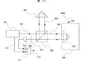
次に本発明の第6の実施例として、プローブ光が1/4波長板とターゲットミラーとの間の光路を4往復する場合について、図7により説明する。本実施例の変位計測装置では、光源ユニット2及び位相検出ユニット18の基本構成とその機能は第1の実施例と同様であるので、説明を省略する。また、本実施例において、光源2の代わりに、第2の実施例で説明した光源2’を用いてもよい。Next, as a sixth embodiment of the present invention, the case where the probe light reciprocates four times in the optical path between the quarter-wave plate and the target mirror will be described with reference to FIG. In the displacement measuring apparatus of the present embodiment, the basic configurations and functions of the
以下では、干渉計ユニット703についてのみ説明する。光源ユニット2から出射された2周波直交偏光ビーム4または32は干渉計ユニット703に入射し、ミラー71で反射された後、非偏光ビームスプリッタ70により2つの光路に分離される。非偏光ビームスプリッタ70を透過した2周波直交偏光ビーム72は、図1(c)の破線7aで示すように両偏光方向に対し45°方向に偏光角を有する偏光板7を透過することによりヘテロダイン干渉する。このヘテロダイン干渉光は光電変換素子8で受光されビート周波数fBの電気信号79に変換され、参照信号として用いられる。Only the
一方、非偏光ビームスプリッタ70で反射された2周波直交偏光ビーム73は、参照ミラー11に入射する。参照ミラー11は、第1の実施例と同様、図2に示すように、合成石英基板11b上にAl等の金属材料で回折格子が形成された構成となっており、その機能は第1の実施例と全く同一であり、偏光素子(Wire Grid Polarizer)として機能する。参照ミラー11で反射されたS偏光ビーム10rは参照光として非偏光ビームスプリッタ70を透過し、反射面70m及び70nで反射された後、再び非偏光ビームスプリッタ70を透過し、参照ミラー11で反射された後、非偏光ビームスプリッタ70で反射される。 On the other hand, the two-frequency
一方、参照ミラー11を透過したP偏光ビーム10mはプローブ光として用いる。P偏光ビーム10mは1/4波長板12を透過した後円偏光となり、ターゲットミラー13で反射され、再び1/4波長板12を透過後S偏光となり、参照ミラー11で反射され、1/4波長板12を透過後円偏光としてターゲットミラー13で反射され、1/4波長板12を透過後P偏光となり、参照ミラー11を透過する。 On the other hand, the P-polarized
このP偏光ビーム10mは参照光と同一の光路を通り、非偏光ビームスプリッタ70を透過し、反射面70m及び70nで反射された後、再び非偏光ビームスプリッタ70を透過し、再度1/4波長板12を透過した後円偏光となり、ターゲットミラー13で反射され、再び1/4波長板12を透過後S偏光となり、参照ミラー11で反射され、1/4波長板12を透過後円偏光としてターゲットミラー13で反射され、1/4波長板12を透過後P偏光となり、参照ミラー11を透過する。即ち、プローブ光10mは参照ミラー11とターゲットミラー13との間の光路を4往復することになり、測定対象物1の移動量1dを4倍に拡大して検出することになる。 This P-polarized
このP偏光ビーム10mは参照光であるS偏光ビーム10rと合成されて2周波直交偏光ビーム74となり、非偏光ビームスプリッタ70で反射された後、ミラー71で反射される。2周波直交偏光ビーム74は、図1(c)の破線15aで示すように両偏光方向に対し45°方向に偏光角を有する偏光板15を透過することによりヘテロダイン干渉する。このヘテロダイン干渉光は光電変換素子16で受光され、電気信号77に変換される。以降の動作、信号処理は第1の実施例と同様であるので、説明を省略する。 This P-polarized
図7から明らかなように、第1の実施例と同様、ターゲットミラー13に向かうプローブ光10mと参照光10rの2つのビームは、光源ユニット2から出射されて干渉計ユニット703に入射し、参照ミラー11に至るまで、更に参照ミラー11から光電変換素子16で受光されるに至るまで、完全に同一の光路を通る。即ち、共通光路形干渉計の構成となる。 As is clear from FIG. 7, as in the first embodiment, the two beams of the
従って、仮に光路中に空気の揺らぎ等による温度分布や屈折率分布、あるいは機械振動が生じたとしても、これらの外乱は両ビームに等しく影響を及ぼすため、両ビームが干渉した際にこれら外乱の影響は完全に相殺され、干渉光は外乱の影響を受けない。唯一、参照ミラー11とターゲットミラー13との間の光路においてプローブ光10mのみが存在するが、例えば、プローブ顕微鏡等のストロークは高々数百ミクロン程度であるので、参照ミラー11とターゲットミラー13との間隙は1mm以下に設定することが可能であり、このような微小間隙での外乱の影響は無視できる。 Therefore, even if a temperature distribution, refractive index distribution, or mechanical vibration occurs due to air fluctuations in the optical path, these disturbances affect both beams equally, so when both beams interfere, The influence is completely cancelled, and the interference light is not affected by the disturbance. Only the
また、図1(b)に示す光源ユニット2では、直交する2つの偏光ビーム24、28が別光路を通る構成となっており、両光路間に外乱の影響が重畳する可能性がある。しかし、仮に外乱の影響がのったとしても、その影響は測定されたヘテロダイン干渉光と参照光の両方に等しくのるため、位相検出ユニット18において両者の位相差を検出する際に相殺される。 Further, in the
本実施例の干渉計の構成により、温度、湿度、音響振動といった環境因子を高精度に制御することなく、測定対象物1の移動速度V及び移動量1dをサブナノメートルからピコメートルの精度で安定に計測することが可能である。本実施例では、参照ミラーとして金属回折格子(Wire Grid Polarizer)を用いることにより、2周波直交偏光ビームのうち一方の偏光ビームからプローブ光を、他方の偏光ビームから参照光を同軸上に生成することが可能となり、共通光路形ヘテロダイン干渉計を構成することができるものである。更に、本実施例では、プローブ光10mが参照ミラー11とターゲットミラー13との間の光路を4往復することになり、測定対象物1の移動量1dを4倍に拡大して検出することになり、第1の実施例に対し2倍の変位計測感度が得られる。 With the configuration of the interferometer of the present embodiment, the moving speed V and the moving
第1から第6の実施例はいずれもヘテロダイン共通光路形干渉計を基本系としているが、次に本発明の第7の実施例として、ホモダイン共通光路形干渉計を基本系とする場合について、図8により説明する。本実施例の変位計測装置は、図8(a)に示すように、光源ユニット802、干渉計ユニット803及び変位検出ユニット102から成る。図8(b)に示すように、光源ユニット802においては、直線偏光レーザ821(例えば波長632.8nmの周波数安定化He−Neレーザ)からの出射ビーム822を45°の偏光方向で偏光ビームスプリッタ823に入射し、2つの偏光成分、P偏光ビーム824とS偏光ビーム828とに分離する。P偏光ビーム824は偏光ビームスプリッタ823を透過し、S偏光ビーム828は偏光ビームスプリッタ823で反射され、各々ミラー826、826’で反射された後、偏光ビームスプリッタ827で合成された、ミラー826”で反射されて、直交偏光ビーム881として出射される。In any of the first to sixth embodiments, a heterodyne common optical path type interferometer is used as a basic system. Next, as a seventh embodiment of the present invention, a homodyne common optical path type interferometer is used as a basic system. This will be described with reference to FIG. As shown in FIG. 8A, the displacement measuring apparatus of this embodiment includes a
即ち、本実施例では、第1の実施例のように、直交偏光ビームに対し光周波数シフトは与えない。図1(c)中の24Pが直交偏光ビーム4のP偏光ビーム824の偏光方向を、28SがS偏光ビーム828の偏光方向を示している。 That is, in this embodiment, unlike the first embodiment, no optical frequency shift is given to the orthogonal polarization beam. In FIG. 1C, 24P indicates the polarization direction of the P-polarized
図8(a)に示すように、直交偏光ビーム881は干渉計ユニット803に入射する。干渉計ユニット803において、非偏光ビームスプリッタ805を透過した直交偏光ビーム882は参照ミラー811に入射する。参照ミラー811は、第1の実施例と同様、図2に示すように、合成石英基板11b上にAl等の金属材料で回折格子が形成された構成となっており、その機能は第1の実施例と全く同一であり、偏光素子(Wire Grid Polarizer)として機能する。 As shown in FIG. 8A, the orthogonally polarized
参照ミラー811で反射されたS偏光ビーム10rは参照光として用いる。透過したP偏光ビーム10mはプローブ光として用いる。P偏光ビーム10mは1/4波長板812を透過した後円偏光となり、ターゲットミラー13で反射され、再び1/4波長板812を透過後S偏光となり、参照ミラー811で反射され、1/4波長板812を透過後円偏光としてターゲットミラー13で反射され、1/4波長板812を透過後P偏光となり、参照ミラー811を透過する。即ち、プローブ光10mは参照ミラー811とターゲットミラー13との間の光路を2往復することになり、測定対象物1の移動量1dを2倍に拡大して検出することになる。 The S-polarized beam 10r reflected by the
参照ミラー811で反射されたS偏光ビーム10rと透過したP偏光ビーム10mは合成されて、直交偏光ビーム883として非偏光ビームスプリッタ805で反射される。この直交偏光ビーム883は1/2波長板884を透過後偏光方向が45°回転し、非偏光ビームスプリッタ885で2つのビームに分離される。非偏光ビームスプリッタ885で反射された直交偏光ビーム886は偏光ビームスプリッタ887に入射し、互いに位相が180°シフトした2つのホモダイン干渉光888及び890に分離される。ホモダイン干渉光888はホトダイオード等の光電変換素子889で受光され、電気信号92に変換される。位相が180°シフトしたホモダイン干渉光890は光電変換素子891で受光され、電気信号93に変換される。 The S-polarized beam 10r reflected by the
非偏光ビームスプリッタ885を透過した直交偏光ビーム894は1/4波長板895透過後±90°の位相差が付加されて、偏光ビームスプリッタ887に入射し、更に互いに位相が180°シフトした2つのホモダイン干渉光896及び898に分離される。ホモダイン干渉光896はホトダイオード等の光電変換素子897で受光され、電気信号100に変換される。位相が180°シフトしたホモダイン干渉光898は光電変換素子899で受光され、電気信号101に変換される。 The orthogonally polarized
4つのホモダイン干渉信号92、93、100、101は各々(数3)〜(数6)で与えられる。 Four homodyne interference signals 92, 93, 100, and 101 are given by (Equation 3) to (Equation 6), respectively.
I1=Im+Ir+2(Im・Ir)1/2cos(4πnD/λ) ・・・(数3)
I2=Im+Ir+2(Im・Ir)1/2cos(4πnD/λ+π)
=Im+Ir−2(Im・Ir)1/2cos(4πnD/λ) ・・・(数4)
I3=Im+Ir+2(Im・Ir)1/2cos(4πnD/λ+π/2)
=Im+Ir−2(Im・Ir)1/2sin(4πnD/λ) ・・・(数5)
I4=Im+Ir+2(Im・Ir)1/2cos(4πnD/λ+3π/2)
=Im+Ir+2(Im・Ir)1/2sin(4πnD/λ) ・・・(数6)
ここで、Imはプローブ光の検出強度、Irは参照光の検出強度、nは空気の屈折率、Dは測定対象物1の移動量1d、λはレーザ光822の波長である。変位検出ユニット102では、(数3)〜(数6)より(数7)に基づいて、測定対象物1の移動量Dが算出されて、移動量信号103として出力される。I1 = Im + Ir +2 (Im · Ir )1/2 cos (4πnD / λ) (Equation 3)
I2 = Im + Ir +2 (Im · Ir )1/2 cos (4πnD / λ + π)
= Im + Ir −2 (Im · Ir )1/2 cos (4πnD / λ) (Equation 4)
I3 = Im + Ir +2 (Im · Ir )1/2 cos (4πnD / λ + π / 2)
= Im + Ir −2 (Im · Ir )1/2 sin (4πnD / λ) (Equation 5)
I4 = Im + Ir +2 (Im · Ir )1/2 cos (4πnD / λ + 3π / 2)
= Im + Ir +2 (Im · Ir )1/2 sin (4πnD / λ) (Equation 6)
Here, Im detected intensity of the probe light, the detection intensity of Ir is the reference light, n is the refractive index of the air, D is the
D=(λ/4πn)tan−1{(I4−I3)/(I1−I2)} ・・・(数7)
図8(a)から明らかなように、ターゲットミラー13に向かうプローブ光10mと参照光10rの2つのビームは、光源ユニット802から出射されて干渉計ユニット803に入射し、参照ミラー811に至るまで、更に参照ミラー811から光電変換素子889、891、897、899で受光されるに至るまで、完全に同一の光路を通る。即ち、共通光路形干渉計の構成となる。D = (λ / 4πn) tan−1 {(I4 −I3 ) / (I1 −I2 )} (Expression 7)
As is clear from FIG. 8A, the two beams of the
従って、仮に光路中に空気の揺らぎ等による温度分布や屈折率分布、あるいは機械振動が生じたとしても、これらの外乱は両ビームに等しく影響を及ぼすため、両ビームが干渉した際にこれら外乱の影響は完全に相殺され、干渉光は外乱の影響を受けない。唯一、参照ミラー811とターゲットミラー13との間の光路においてプローブ光10mのみが存在するが、例えば、プローブ顕微鏡等のストロークは高々数百ミクロン程度であるので、参照ミラー811とターゲットミラー13との間隙は1mm以下に設定することが可能であり、このような微小間隙での外乱の影響は無視できる。また、図8(b)に示す光源ユニット802では、直交する2つの偏光ビーム824、828が別光路を通る構成となっており、両光路間に外乱の影響が重畳する可能性がある。しかし、仮に外乱の影響がのったとしても、その影響は測定された4つのホモダイン干渉光に等しくのるため、変位検出ユニット102における(数7)の処理において相殺される。 Therefore, even if a temperature distribution, refractive index distribution, or mechanical vibration occurs due to air fluctuations in the optical path, these disturbances affect both beams equally, so when both beams interfere, The influence is completely cancelled, and the interference light is not affected by the disturbance. Only the
本実施例の干渉計の構成により、温度、湿度、音響振動といった環境因子を高精度に制御することなく、測定対象物1の移動速度V及び移動量1dをサブナノメートルからピコメートルの精度で安定に計測することが可能である。本実施例では、参照ミラーとして金属回折格子(Wire Grid Polarizer)を用いることにより、直交偏光ビームのうち一方の偏光ビームからプローブ光を、他方の偏光ビームから参照光を同軸上に生成することが可能となり、共通光路形ホモダイン干渉計を構成することができるものである。 With the configuration of the interferometer of the present embodiment, the moving speed V and the moving
次に本発明の第8の実施例として、第7の実施例と同様ホモダイン干渉計を基本系とする場合について、図9により説明する。本実施例の変位計測装置は、第7の実施例と同様、光源ユニット802、干渉計ユニット903及び変位検出ユニット102から成るが、光源ユニット802及び変位検出ユニット102の構成と機能は第7の実施例と同一であるので、説明を省略する。光源ユニット802から出射された直交偏光ビーム881は干渉計ユニット903に入射する。干渉計ユニット903において、非偏光ビームスプリッタ905を透過した直交偏光ビーム982は参照ミラー911に入射する。参照ミラー911は、第1の実施例の参照ミラー11と同様、図2に示すように、合成石英基板11b上にAl等の金属材料で回折格子が形成された構成となっており、その機能は第1の実施例と全く同一であり、偏光素子(Wire Grid Polarizer)として機能する。参照ミラー911で反射されたS偏光ビーム10rは参照光として用いる。Next, as an eighth embodiment of the present invention, a case where a homodyne interferometer is used as a basic system as in the seventh embodiment will be described with reference to FIG. As in the seventh embodiment, the displacement measuring apparatus of the present embodiment includes a
透過したP偏光ビーム10mはプローブ光として用いる。P偏光ビーム10mは1/4波長板912を透過した後円偏光となり、ターゲットミラー13で反射され、再び1/4波長板912を透過後S偏光となり、参照ミラー911で反射され、1/4波長板912を透過後円偏光としてターゲットミラー13で反射され、1/4波長板912を透過後P偏光となり、参照ミラー911を透過する。即ち、プローブ光10mは参照ミラー911とターゲットミラー13との間の光路を2往復することになり、測定対象物1の移動量1dを2倍に拡大して検出することになる。参照ミラー911で反射されたS偏光ビーム10rと透過したP偏光ビーム10mは合成されて、直交偏光ビーム983として非偏光ビームスプリッタ905で反射される。この直交偏光ビーム983はビームエキスパンダ201で拡大される。 The transmitted P-polarized
この拡大ビーム202はDOE203(Diffractive Optical Element:回折光学素子)により4つの直交偏光ビーム204、205、206、207に分割され、複屈折材料で構成された位相シフトマスク208に入射する。この位相シフトマスク208は、4つの直交偏光ビーム204〜207に対応した4つの領域208a、208b、208c、208dに分割されており、各領域を透過する互いに直交する偏光ビームの間に、0°、90°、180°、270°の位相シフトを与える。位相シフトが与えられた4つの直交偏光ビームは、更に両偏光方向に対し45°方向に偏光角を有する偏光板209を透過することによりホモダイン干渉する。 The expanded
4つのホモダイン干渉光210〜213は4分割された光電変換素子214で受光され、電気信号215〜218に変換される。4つのホモダイン干渉信号215〜218は、第7の実施例と同様、各々(数3)〜(数6)で与えられる。変位検出ユニット102では、(数3)〜(数6)より(数7)に基づいて、測定対象物1の移動量Dが算出されて、移動量信号103として出力される。 The four homodyne interference lights 210 to 213 are received by the four-divided
図9から明らかなように、ターゲットミラー13に向かうプローブ光10mと参照光10rの2つのビームは、光源ユニット902から出射されて干渉計ユニット903に入射し、参照ミラー911に至るまで、更に参照ミラー911から光電変換素子214で受光されるに至るまで、同じ光路を通る。即ち、共通光路形干渉計の構成となる。従って、仮に光路中に空気の揺らぎ等による温度分布や屈折率分布、あるいは機械振動が生じたとしても、これらの外乱は両ビームに等しく影響を及ぼすため、両ビームが干渉した際にこれら外乱の影響は完全に相殺され、干渉光は外乱の影響を受けない。唯一、参照ミラー911とターゲットミラー13との間の光路においてプローブ光10mのみが存在するが、例えば、プローブ顕微鏡等のストロークは高々数百ミクロン程度であるので、参照ミラー911とターゲットミラー13との間隙は1mm以下に設定することが可能であり、このような微小間隙での外乱の影響は無視できる。 As is clear from FIG. 9, the two beams of the
本実施例の干渉計の構成により、温度、湿度、音響振動といった環境因子を高精度に制御することなく、測定対象物1の移動速度V及び移動量1dをサブナノメートルからピコメートルの精度で安定に計測することが可能である。本実施例では、参照ミラーとして金属回折格子(Wire Grid Polarizer)を用いることにより、直交偏光ビームのうち一方の偏光ビームからプローブ光を、他方の偏光ビームから参照光を同軸上に生成することが可能となり、共通光路形ホモダイン干渉計を構成することができるものである。また、本実施例では、位相シフトされた4つの干渉光の生成に、DOE203と平面状の位相シフトマスク208を用いているため、干渉計ユニット3の構成が簡素化されてより安定性が増し、更に寸法が小さくなるという利点がある。従って、測定対象物1の周辺にスペースが無い場合でも適用可能である。 With the configuration of the interferometer of the present embodiment, the moving speed V and the moving
以上、本発明の実施例を、測定対象物1の移動量1dを計測する場合を例にとり説明した。測定対象物1としては、半導体露光装置や検査装置等のステージ等、プローブ顕微鏡のプローブあるいは測定試料搭載ステージ等、また加工用の工具(バイト等)が想定される。更に、本発明はこれらの実施例に限定されるものではなく、例えばターゲットミラー13を除去し、対象物1表面にプローブ光10mを直接照射し、プローブ光10mに対し直交する方向に対象物1を移動させつつ測定を行えば、対象物1表面の微小な凹凸をサブナノメートルからピコメートルの分解能で高精度に計測することも可能である。この場合の対象物としては、磁気ディスク表面や磁気ヘッド浮上面の面粗さ、マイクロレンズ等のMEMS(Micro−Electro−Mechanical Systems)部品等が考えられる。また、参照ミラー11と対象物1との間に集光レンズを挿入すれば、面内空間分解能もサブミクロンオーダに達する。 The embodiment of the present invention has been described above by taking the case of measuring the
また、本発明の第3の実施例を、第4〜第8の実施例に組み合わせうることも自明である。 It is also obvious that the third embodiment of the present invention can be combined with the fourth to eighth embodiments.
1、400・・・測定対象物 2、2’、802・・・光源ユニット 3、503、603、703、803、903・・・干渉計ユニット 5、85・・・非偏光ビームスプリッタ 7、15、209、307・・・偏光板 8、16、89、91、97、99、214、308・・・光電変換素子 11・・・参照ミラー 11b・・・合成石英基板 11g・・・回折格子 12、95・・・1/4波長板 13・・・ターゲットミラー 18・・・位相検出ユニット 21・・・直線偏光レーザ 23、27、41、87、303・・・偏光ビームスプリッタ 25、29・・・音響光学変調素子 31・・・2周波He−Neレーザ 44・・・偏波面保存ファイバ 50・・・複屈折プリズム 51・・・複屈折材料 52、66・・・反射ミラー 60・・・偏光ビームスプリッタ 70・・・非偏光ビームスプリッタ 84・・・1/2波長板 102・・・変位検出ユニット 201・・・ビームエキスパンダ 203・・・DOE 208・・・位相シフトマスク 304、306・・・直角プリズム 311・・・位相検出回路
DESCRIPTION OF SYMBOLS 1,400 ...
Claims (8)
Translated fromJapanese前記偏光素子を透過した前記第1の偏光状態の透過光を対象物に照射し前記対象物で反射した前記第1の偏光状態の反射光と、前記偏光素子で反射した前記第2の偏光状態の反射光と、をホモダイン干渉させて干渉光を生じさせ、
前記干渉光に含まれている情報から前記対象物の変位情報を求めることを特徴とする変位計測方法であって、
前記第1の偏光状態の透過光の光軸と、前記第1の偏光状態の反射光の光軸と、前記第2の偏光状態の反射光の光軸とは同軸であることを特徴とする変位計測方法。A single-polarized linearly polarized light including light in two polarization states whose polarization directions are orthogonal to each otheris transmitted through the light in the first polarization state, and the second polarization whose polarization direction is orthogonal to the light in the first polarization state Irradiatethe polarizing elementthat reflects the light of the state ,
The reflected light of the polarization element is irradiated to the object light transmitted throughthe transmitted through the first polarization state ofthe first polarization state reflected by the object, beforethe second reflected byKihen optical element The interference light is generated byhomodyne interference between the reflected light in the polarization state,
Displacement measurement method characterized by obtaining displacement information of the object from information contained in the interference light,
The optical axis of the transmitted light in the first polarization state, the optical axis of the reflected light in the first polarization state, and the optical axis of the reflected light in the second polarization state are coaxial. Displacement measurement method .
前記偏光素子を透過した前記第1の偏光状態の透過光は、前記偏光素子と前記対象物との間を2往復した後、前記偏光素子を透過して、前記偏光素子で反射した前記第2の偏光状態の反射光と干渉させることを特徴とする変位計測方法。The displacement measuring method accordingto claim 1,
Light transmitted through the first polarization state transmitted through the frontKihen light element, after 2 reciprocates between the frontKihen optical element and the object is transmitted through the frontKihen optical device, beforeKihen A displacement measuring method comprising causing interference with reflected light in the second polarization state reflected by an optical element.
前記偏光素子は、回折格子で構成されることを特徴とする変位計測方法。The displacement measuring method according to claim 1or 2 ,
BeforeKihen optical device is a displacement measurement method characterized in that it is constituted by a diffraction grating.
前記偏光素子は、Wire Grid Polarizerで構成されることを特徴とする変位計測方法。The displacement measuring method according to claim 1or 2 ,
BeforeKihen optical device is a displacement measurement method characterized in that it is constituted by a Wire Grid Polarizer.
第1の偏光状態の光を透過し、前記第1の偏光状態の光と偏光方向が直交する第2の偏光状態の光を反射する偏光素子と、
前記光源からの光を前記偏光素子に照射する照射手段と、
前記偏光素子を透過した前記第1の偏光状態の透過光を対象物に照射し前記対象物で反射した前記第1の偏光状態の反射光と、前記偏光素子で反射した前記第2の偏光状態の反射光と、をホモダイン干渉させて干渉光を生じさせる干渉手段と、
前記干渉手段で生じさせた干渉光を検出して前記対象物の変位情報を求める変位情報抽出手段と、
を備え、
前記干渉手段は、前記第1の偏光状態の透過光の光軸と、前記第1の偏光状態の反射光の光軸と、前記第2の偏光状態の反射光の光軸とが同軸となるように構成したことを特徴とする変位計測装置。A light source thatemits linearly polarized light of a single wavelength including light in two polarization states whose polarization directions are orthogonal to each other ;
A polarizing element that transmits light in a first polarization state and reflects light in a second polarization state whose polarization direction is orthogonal to the light in the first polarization state ;
Irradiating means for irradiating a light from the light source beforeKihen optical element,
BeforeKihen light element reflected light transmitted throughsaid first ofsaid first polarization state transmitted light is irradiated to the object and reflected by the object of the polarization state,the first reflected in the previousKihen optical element Interference means for causing interference light by causinghomodyne interference between the reflected light of two polarization states;
Displacement information extraction means for detecting interference light generated by the interference means and obtaining displacement information of the object;
Equipped witha,
In the interference means, the optical axis of the transmitted light in the first polarization state, the optical axis of the reflected light in the first polarization state, and the optical axis of the reflected light in the second polarization state are coaxial. Displacement measuring apparatus characterizedby being configured as described above .
前記干渉手段は、前記偏光素子と対象物との間に配置した1/4波長板を有することを特徴とする変位計測装置。The displacement measuring device according to claim5 ,
The interference means before the displacement measuring apparatus characterized by having a quarter wave plate disposedbetween theKihen optical elementand the object.
前記偏光素子は、回折格子で構成されることを特徴とする変位計測装置。The displacement measuring device according to claim5 or 6 ,
BeforeKihen optical device is a displacement measuring apparatus characterized by being constituted by a diffraction grating.
前記偏光素子は、Wire Grid Polarizerで構成されることを特徴とする変位計測装置。The displacement measuring device according to claim5 or 6 ,
BeforeKihen optical device is a displacement measuring apparatus characterized by being composed of a Wire Grid Polarizer.
Priority Applications (6)
| Application Number | Priority Date | Filing Date | Title |
|---|---|---|---|
| JP2005090460AJP4939765B2 (en) | 2005-03-28 | 2005-03-28 | Displacement measuring method and apparatus |
| US11/188,732US7612889B2 (en) | 2005-03-28 | 2005-07-26 | Method and apparatus for measuring displacement of a sample |
| DE602005012228TDE602005012228D1 (en) | 2005-03-28 | 2005-07-26 | Method and device for measuring the distance of a sample |
| EP05016216AEP1707916B1 (en) | 2005-03-28 | 2005-07-26 | Method and apparatus for measuring displacement of a sample |
| US12/605,089US8064066B2 (en) | 2005-03-28 | 2009-10-23 | Method and apparatus for measuring displacement of a sample to be inspected using an interference light |
| US13/302,948US8659761B2 (en) | 2005-03-28 | 2011-11-22 | Method and apparatus for measuring displacement of a sample using a wire grid polarizer to generate interference light |
Applications Claiming Priority (1)
| Application Number | Priority Date | Filing Date | Title |
|---|---|---|---|
| JP2005090460AJP4939765B2 (en) | 2005-03-28 | 2005-03-28 | Displacement measuring method and apparatus |
Related Child Applications (1)
| Application Number | Title | Priority Date | Filing Date |
|---|---|---|---|
| JP2009296689ADivisionJP5093220B2 (en) | 2009-12-28 | 2009-12-28 | Displacement measuring method and apparatus |
Publications (2)
| Publication Number | Publication Date |
|---|---|
| JP2006275531A JP2006275531A (en) | 2006-10-12 |
| JP4939765B2true JP4939765B2 (en) | 2012-05-30 |
Family
ID=35311328
Family Applications (1)
| Application Number | Title | Priority Date | Filing Date |
|---|---|---|---|
| JP2005090460AExpired - Fee RelatedJP4939765B2 (en) | 2005-03-28 | 2005-03-28 | Displacement measuring method and apparatus |
Country Status (4)
| Country | Link |
|---|---|
| US (3) | US7612889B2 (en) |
| EP (1) | EP1707916B1 (en) |
| JP (1) | JP4939765B2 (en) |
| DE (1) | DE602005012228D1 (en) |
Families Citing this family (26)
| Publication number | Priority date | Publication date | Assignee | Title |
|---|---|---|---|---|
| JP4869656B2 (en)* | 2005-08-08 | 2012-02-08 | 株式会社ミツトヨ | Interferometer |
| US7928409B2 (en)* | 2005-10-11 | 2011-04-19 | The United States Of America As Represented By The Secretary Of Commerce | Real-time, active picometer-scale alignment, stabilization, and registration in one or more dimensions |
| JP2008286518A (en)* | 2007-05-15 | 2008-11-27 | Hitachi Ltd | Displacement measuring method and apparatus |
| JP5133614B2 (en)* | 2007-06-22 | 2013-01-30 | 株式会社ブリヂストン | 3D shape measurement system |
| GB0715102D0 (en)* | 2007-08-03 | 2007-09-12 | Infinitesima Ltd | Vibration correction for probe microscopy and a method thereof |
| TWI447351B (en)* | 2009-02-24 | 2014-08-01 | Univ Nat Taipei Technology | Orthogonal-polarization mirau interferometry and beam-splitting module and interferometric system using the same |
| US8387158B2 (en)* | 2009-08-05 | 2013-02-26 | The United States of America as represented by the Secretary of Commerce, the National Institute of Standards and Technology | Laser guided tip approach with 3D registration to a surface |
| JP5629455B2 (en)* | 2009-12-14 | 2014-11-19 | キヤノン株式会社 | Interferometer |
| CN102661709B (en)* | 2012-04-23 | 2014-08-13 | 清华大学 | Large-journey measuring method of moving platform displacement |
| US20140149023A1 (en)* | 2012-11-29 | 2014-05-29 | Ford Global Technologies, Llc | Method and system for engine position control |
| US20140149018A1 (en)* | 2012-11-29 | 2014-05-29 | Ford Global Technologies, Llc | Engine with laser ignition and measurement |
| DE102013212640A1 (en)* | 2013-06-28 | 2014-12-31 | Robert Bosch Gmbh | Device for emitting electromagnetic radiation |
| CN103644849B (en)* | 2013-12-12 | 2016-02-03 | 哈尔滨工业大学 | A kind of three dimensional grating displacement measurement system surveying vertical displacement |
| CN103644848B (en)* | 2013-12-12 | 2016-02-03 | 哈尔滨工业大学 | A kind of three dimensional grating displacement measurement system using double-frequency laser |
| CN105045042B (en)* | 2015-04-23 | 2017-06-16 | 清华大学 | A kind of silicon wafer stage exposure area six-degree of freedom displacement measuring method |
| KR20180041168A (en)* | 2015-08-17 | 2018-04-23 | 큐에스오 인터페로메터 시스템즈 에이비 | Method and apparatus for deriving a topography of a target surface |
| CN105547157B (en)* | 2016-03-07 | 2018-04-06 | 安徽电气工程职业技术学院 | Three-dimensional micro-nano trigger probe |
| CN105627949B (en)* | 2016-03-07 | 2017-12-26 | 合肥工业大学 | Optical sensing formula three-dimensional high-precision contact scanning measuring probe |
| US10094648B2 (en)* | 2016-06-30 | 2018-10-09 | Keysight Technologies, Inc. | Homodyne optical sensor system incorporating a multi-phase beam combining system |
| US10508898B2 (en)* | 2017-03-23 | 2019-12-17 | Hitachi, Ltd. | Interference measurement device having a variable phase element |
| CN108286943B (en)* | 2018-01-15 | 2020-10-16 | 中国科学院长春光学精密机械与物理研究所 | Displacement measurement optical system applied to workbench of photoetching system |
| EP3595196A1 (en)* | 2018-07-12 | 2020-01-15 | Nederlandse Organisatie voor toegepast- natuurwetenschappelijk onderzoek TNO | Laser device for optical communication, optical communication system and use of these |
| US11262191B1 (en)* | 2018-07-12 | 2022-03-01 | Onto Innovation Inc. | On-axis dynamic interferometer and optical imaging systems employing the same |
| CN112739981B (en)* | 2021-02-23 | 2022-05-06 | 华为技术有限公司 | An optical system, device and terminal |
| CN119779634A (en)* | 2024-12-20 | 2025-04-08 | 中国科学院西安光学精密机械研究所 | Air refractive index self-correction dual-frequency laser interferometer and wavefront aberration detection method |
| CN119779633A (en)* | 2024-12-20 | 2025-04-08 | 中国科学院西安光学精密机械研究所 | Air refractive index self-correcting triple-frequency laser interferometer and wavefront aberration detection method |
Family Cites Families (24)
| Publication number | Priority date | Publication date | Assignee | Title |
|---|---|---|---|---|
| US4711574A (en)* | 1984-04-27 | 1987-12-08 | Hewlett-Packard Company | Minimum deadpath interferometer and dilatometer |
| JPS6227603A (en) | 1985-07-29 | 1987-02-05 | Hitachi Ltd | Optical displacement measurement device |
| US4784490A (en)* | 1987-03-02 | 1988-11-15 | Hewlett-Packard Company | High thermal stability plane mirror interferometer |
| JPH01206283A (en)* | 1988-02-13 | 1989-08-18 | Brother Ind Ltd | Optical heterodyne measurement device |
| JPH01318902A (en)* | 1988-06-20 | 1989-12-25 | Hitachi Ltd | Measuring apparatus for displacement by two-wavelength optical heterodyne system |
| JPH0225803A (en)* | 1988-07-14 | 1990-01-29 | Kuraray Co Ltd | polarizing beam splitter |
| JP2760830B2 (en) | 1989-01-20 | 1998-06-04 | 株式会社日立製作所 | Optical measuring device for displacement |
| US4883357A (en)* | 1989-03-01 | 1989-11-28 | Zygo Corporation | Dual high stability interferometer |
| DE69017159T2 (en)* | 1989-12-11 | 1995-08-10 | Konishiroku Photo Ind | Laser interferometric measuring device. |
| DE3942896A1 (en) | 1989-12-23 | 1991-06-27 | Zeiss Carl Fa | INTERFEROMETRIC SENSOR FOR MEASURING DISTANCE CHANGES IN A SMALL AREA |
| US5172186A (en) | 1990-07-03 | 1992-12-15 | Konica Corporation | Laser interferometry length measuring an apparatus employing a beam slitter |
| JP2821817B2 (en)* | 1991-03-11 | 1998-11-05 | コニカ株式会社 | Differential interference prism |
| US5289434A (en)* | 1992-09-18 | 1994-02-22 | Shell Oil Company | Retroreflector apparatus for remote seismic sensing |
| US5404222A (en)* | 1994-01-14 | 1995-04-04 | Sparta, Inc. | Interferametric measuring system with air turbulence compensation |
| GB2293249A (en)* | 1994-09-09 | 1996-03-20 | Sharp Kk | Polarisation sensitive device and a method of manufacture thereof |
| JP2000097666A (en) | 1998-09-22 | 2000-04-07 | Nikon Corp | Surface shape measuring interferometer, wavefront aberration measuring device, method for manufacturing projection optical system using the interferometer and the wavefront aberration measuring device, and method for calibrating the interferometer |
| US6312373B1 (en) | 1998-09-22 | 2001-11-06 | Nikon Corporation | Method of manufacturing an optical system |
| JP2002540446A (en)* | 1999-03-22 | 2002-11-26 | エムイーエムエス・オプティカル・インコーポレイテッド | Diffraction selective polarization beam splitter and beam routing prism produced thereby |
| JP2000310507A (en)* | 1999-04-26 | 2000-11-07 | Canon Inc | Interference device |
| EP1347315A1 (en) | 2000-12-28 | 2003-09-24 | Fuji Electric Co., Ltd. | Light guiding plate and liquid crystal display device with the light guiding plate |
| DE10202120A1 (en)* | 2002-01-21 | 2003-07-31 | Scinex Ag Zug | Interferometric optical arrangement |
| JP4063042B2 (en) | 2002-10-23 | 2008-03-19 | ウシオ電機株式会社 | Polarized light irradiation device for photo-alignment |
| US6992778B2 (en)* | 2003-08-08 | 2006-01-31 | Mitutoyo Corporation | Method and apparatus for self-calibration of a tunable-source phase shifting interferometer |
| JP2008286518A (en)* | 2007-05-15 | 2008-11-27 | Hitachi Ltd | Displacement measuring method and apparatus |
- 2005
- 2005-03-28JPJP2005090460Apatent/JP4939765B2/ennot_activeExpired - Fee Related
- 2005-07-26DEDE602005012228Tpatent/DE602005012228D1/ennot_activeExpired - Lifetime
- 2005-07-26USUS11/188,732patent/US7612889B2/ennot_activeExpired - Fee Related
- 2005-07-26EPEP05016216Apatent/EP1707916B1/ennot_activeCeased
- 2009
- 2009-10-23USUS12/605,089patent/US8064066B2/ennot_activeExpired - Fee Related
- 2011
- 2011-11-22USUS13/302,948patent/US8659761B2/ennot_activeExpired - Fee Related
Also Published As
| Publication number | Publication date |
|---|---|
| US7612889B2 (en) | 2009-11-03 |
| EP1707916B1 (en) | 2009-01-07 |
| US20120062903A1 (en) | 2012-03-15 |
| EP1707916A1 (en) | 2006-10-04 |
| US8659761B2 (en) | 2014-02-25 |
| DE602005012228D1 (en) | 2009-02-26 |
| US20060215171A1 (en) | 2006-09-28 |
| US8064066B2 (en) | 2011-11-22 |
| US20100039652A1 (en) | 2010-02-18 |
| JP2006275531A (en) | 2006-10-12 |
Similar Documents
| Publication | Publication Date | Title |
|---|---|---|
| JP4939765B2 (en) | Displacement measuring method and apparatus | |
| CN107003155B (en) | Interferometric encoder system | |
| JP4030960B2 (en) | Dynamic interferometry control of input beam direction | |
| US6819434B2 (en) | Multi-axis interferometer | |
| WO2007020856A1 (en) | Method and equipment for measuring displacement, stage equipment and probe microscope | |
| JP6162137B2 (en) | Low coherence interferometry using an encoder system | |
| JP4198929B2 (en) | Laser length measuring instrument and laser length measuring method | |
| KR20010041209A (en) | Interferometer and method for measuring the refractive index and optical path length effects of air | |
| CN104792424A (en) | Equal optical path position adjusting method of optical fiber point diffraction interferometer | |
| JP5348224B2 (en) | Displacement measuring method and apparatus | |
| CN115727756A (en) | Heterodyne light source for a metrology system | |
| JP5093220B2 (en) | Displacement measuring method and apparatus | |
| JPH11183116A (en) | Light wave interference measurement method and apparatus | |
| US7298493B2 (en) | Interferometric optical assemblies and systems including interferometric optical assemblies | |
| JP2006064451A (en) | Interferometer | |
| JP3421309B2 (en) | Surface shape measuring method and surface shape measuring instrument | |
| EP2652519B1 (en) | Tracking type laser interferometer for objects with rotational degrees of freedom | |
| JP3340792B2 (en) | Microstructure measuring device | |
| JP2005233772A (en) | Interferometer | |
| JP2886755B2 (en) | Microstructure measuring device | |
| JP3184914B2 (en) | Surface shape measuring method and surface shape measuring instrument | |
| JP2002333304A (en) | Optical heterodyne interferometer | |
| JPH0510733A (en) | Three-dimensional shape measuring apparatus | |
| TW202532973A (en) | An optical filter, a heterodyne interferometer system comprising the filter, and a method for filtering an input beam for a heterodyne interferometer | |
| CN115727778A (en) | Digital Holographic Metrology System |
Legal Events
| Date | Code | Title | Description |
|---|---|---|---|
| A621 | Written request for application examination | Free format text:JAPANESE INTERMEDIATE CODE: A621 Effective date:20070320 | |
| A977 | Report on retrieval | Free format text:JAPANESE INTERMEDIATE CODE: A971007 Effective date:20090402 | |
| A131 | Notification of reasons for refusal | Free format text:JAPANESE INTERMEDIATE CODE: A131 Effective date:20090428 | |
| A521 | Request for written amendment filed | Free format text:JAPANESE INTERMEDIATE CODE: A523 Effective date:20090609 | |
| A131 | Notification of reasons for refusal | Free format text:JAPANESE INTERMEDIATE CODE: A131 Effective date:20091027 | |
| A521 | Request for written amendment filed | Free format text:JAPANESE INTERMEDIATE CODE: A523 Effective date:20091228 | |
| A02 | Decision of refusal | Free format text:JAPANESE INTERMEDIATE CODE: A02 Effective date:20100316 | |
| A521 | Request for written amendment filed | Free format text:JAPANESE INTERMEDIATE CODE: A523 Effective date:20100615 | |
| A911 | Transfer to examiner for re-examination before appeal (zenchi) | Free format text:JAPANESE INTERMEDIATE CODE: A911 Effective date:20100624 | |
| A912 | Re-examination (zenchi) completed and case transferred to appeal board | Free format text:JAPANESE INTERMEDIATE CODE: A912 Effective date:20100806 | |
| A521 | Request for written amendment filed | Free format text:JAPANESE INTERMEDIATE CODE: A523 Effective date:20111226 | |
| A01 | Written decision to grant a patent or to grant a registration (utility model) | Free format text:JAPANESE INTERMEDIATE CODE: A01 | |
| A61 | First payment of annual fees (during grant procedure) | Free format text:JAPANESE INTERMEDIATE CODE: A61 Effective date:20120227 | |
| FPAY | Renewal fee payment (event date is renewal date of database) | Free format text:PAYMENT UNTIL: 20150302 Year of fee payment:3 | |
| FPAY | Renewal fee payment (event date is renewal date of database) | Free format text:PAYMENT UNTIL: 20150302 Year of fee payment:3 | |
| LAPS | Cancellation because of no payment of annual fees |