JP4938465B2 - Apparatus and method for separating a large amount of hybrid liquid into at least two components - Google Patents
Apparatus and method for separating a large amount of hybrid liquid into at least two componentsDownload PDFInfo
- Publication number
- JP4938465B2 JP4938465B2JP2006554136AJP2006554136AJP4938465B2JP 4938465 B2JP4938465 B2JP 4938465B2JP 2006554136 AJP2006554136 AJP 2006554136AJP 2006554136 AJP2006554136 AJP 2006554136AJP 4938465 B2JP4938465 B2JP 4938465B2
- Authority
- JP
- Japan
- Prior art keywords
- component
- bag
- flow rate
- separation
- separation bag
- Prior art date
- Legal status (The legal status is an assumption and is not a legal conclusion. Google has not performed a legal analysis and makes no representation as to the accuracy of the status listed.)
- Expired - Fee Related
Links
Images


Classifications
- B—PERFORMING OPERATIONS; TRANSPORTING
- B04—CENTRIFUGAL APPARATUS OR MACHINES FOR CARRYING-OUT PHYSICAL OR CHEMICAL PROCESSES
- B04B—CENTRIFUGES
- B04B5/00—Other centrifuges
- B04B5/04—Radial chamber apparatus for separating predominantly liquid mixtures, e.g. butyrometers
- B—PERFORMING OPERATIONS; TRANSPORTING
- B04—CENTRIFUGAL APPARATUS OR MACHINES FOR CARRYING-OUT PHYSICAL OR CHEMICAL PROCESSES
- B04B—CENTRIFUGES
- B04B13/00—Control arrangements specially designed for centrifuges; Programme control of centrifuges
- A—HUMAN NECESSITIES
- A61—MEDICAL OR VETERINARY SCIENCE; HYGIENE
- A61M—DEVICES FOR INTRODUCING MEDIA INTO, OR ONTO, THE BODY; DEVICES FOR TRANSDUCING BODY MEDIA OR FOR TAKING MEDIA FROM THE BODY; DEVICES FOR PRODUCING OR ENDING SLEEP OR STUPOR
- A61M1/00—Suction or pumping devices for medical purposes; Devices for carrying-off, for treatment of, or for carrying-over, body-liquids; Drainage systems
- A61M1/02—Blood transfusion apparatus
- A61M1/0209—Multiple bag systems for separating or storing blood components
- A—HUMAN NECESSITIES
- A61—MEDICAL OR VETERINARY SCIENCE; HYGIENE
- A61M—DEVICES FOR INTRODUCING MEDIA INTO, OR ONTO, THE BODY; DEVICES FOR TRANSDUCING BODY MEDIA OR FOR TAKING MEDIA FROM THE BODY; DEVICES FOR PRODUCING OR ENDING SLEEP OR STUPOR
- A61M1/00—Suction or pumping devices for medical purposes; Devices for carrying-off, for treatment of, or for carrying-over, body-liquids; Drainage systems
- A61M1/02—Blood transfusion apparatus
- A61M1/029—Separating blood components present in distinct layers in a container, not otherwise provided for
- B—PERFORMING OPERATIONS; TRANSPORTING
- B04—CENTRIFUGAL APPARATUS OR MACHINES FOR CARRYING-OUT PHYSICAL OR CHEMICAL PROCESSES
- B04B—CENTRIFUGES
- B04B13/00—Control arrangements specially designed for centrifuges; Programme control of centrifuges
- B04B2013/006—Interface detection or monitoring of separated components
Landscapes
- Health & Medical Sciences (AREA)
- Heart & Thoracic Surgery (AREA)
- Biomedical Technology (AREA)
- Vascular Medicine (AREA)
- Engineering & Computer Science (AREA)
- Anesthesiology (AREA)
- Hematology (AREA)
- Life Sciences & Earth Sciences (AREA)
- Animal Behavior & Ethology (AREA)
- General Health & Medical Sciences (AREA)
- Public Health (AREA)
- Veterinary Medicine (AREA)
- Pathology (AREA)
- External Artificial Organs (AREA)
- Centrifugal Separators (AREA)
Abstract
Description
Translated fromJapanese本発明は、多量の混成液体を少なくとも2つの成分に分離する装置及び方法に関する。 The present invention relates to an apparatus and method for separating a large volume of mixed liquid into at least two components.
血液成分を処理する装置が、国際公開第03/089027号から周知である。この装置は、少なくとも1つの生成物バッグ、例えば、血小板成分バッグに接続される環状分離バッグと協働するように構成される遠心分離機を備える。遠心分離機は、
―分離バッグを支持するターンテーブルと、分離バッグに接続される生成物バッグを含む中央区画とを有する、ロータと、
―分離バッグを圧搾して、分離バックから生成物バッグへ分離成分(例えば、希薄溶液中に懸濁される血小板)を移送させる、圧搾システムと、
を含む。An apparatus for treating blood components is known from WO 03/089027. The apparatus comprises a centrifuge configured to cooperate with at least one product bag, eg, an annular separation bag connected to a platelet component bag. The centrifuge
A rotor having a turntable supporting the separation bag and a central compartment containing a product bag connected to the separation bag;
A squeezing system that squeezes the separation bag to transfer separation components (eg, platelets suspended in dilute solution) from the separation bag to the product bag;
including.
本発明の目的は、最小限の時間で、全血などの混成液体を少なくとも2つの高品質成分に分離するために最適化分離プロセスを行うことが可能な、遠心分離装置を設計することである。 An object of the present invention is to design a centrifuge that can perform an optimized separation process to separate a mixed liquid, such as whole blood, into at least two high quality components in a minimum amount of time. .
本発明によれば、多量の混成液体(例えば、全血)を少なくとも第1の成分(例えば、血漿、それぞれ、血小板を含む)と、第2の成分(例えば、血小板、それぞれ、単核球を含む)とに分離する装置の第1の実施形態において、多量の混成液体は、少なくとも第1の成分バッグと第2の成分バッグとに接続される軟質分離バッグに含まれ、この実施形態は、
・分離バッグをスピンするロータを有する遠心分離機と、
・分離バッグを圧搾して、分離バッグから第1の成分バッグへ第1の成分を移送させ、かつ、分離バッグから第2の成分バッグへ第2の成分を移送させる、圧搾部材と、
・分離バッグ内に少なくとも第1の成分と第2の成分との沈降を可能にする少なくとも1つの遠心分離速度と、第1の成分バッグへの第1の成分の少なくとも1つの第1の移送流速及び第2の成分バッグへの第2の成分の少なくとも1つの第2の移送流速に関する情報とを格納する、メモリであり、それによって、少なくとも1つの第1の移送流速及び少なくとも1つの第2の移送流速は異なる、メモリと、
―少なくとも1つの遠心分離速度と、少なくとも1つの第1の移送流速と少なくとも1つの第2の移送流速とに関する情報とをメモリから受信するように、
―ロータを少なくとも1つの遠心分離速度で回転させるように、
―分離バッグ内に少なくとも第1の成分と第2の成分とが沈降後、少なくとも1つの第1の移送流速で分離バッグから第1の成分バッグへ第1の成分を移送するように、かつ、少なくとも1つの第2の移送流速で分離バッグから第2の成分バッグへ第2の成分を移送するように、圧搾部材に分離バッグを圧搾させるように、
プログラムされる制御ユニットと、
を備える。According to the present invention, a large amount of mixed liquid (eg, whole blood) is added to at least a first component (eg, plasma, each containing platelets) and a second component (eg, platelets, each containing mononuclear cells). In a first embodiment of the separating device, the bulk of the mixed liquid is contained in at least a soft separation bag connected to the first component bag and the second component bag, this embodiment comprising:
A centrifuge having a rotor that spins the separation bag;
A pressing member that squeezes the separation bag to transfer the first component from the separation bag to the first component bag and to transfer the second component from the separation bag to the second component bag;
At least one centrifuge speed that allows sedimentation of at least a first component and a second component into the separation bag, and at least a first transfer flow rate of the first component into the first component bag. And information relating to at least one second transfer flow rate of the second component to the second component bag, whereby at least one first transfer flow rate and at least one second The transfer flow rate is different, with memory,
-Receiving from the memory at least one centrifugation speed and information on at least one first transfer flow rate and at least one second transfer flow rate;
-To rotate the rotor at at least one centrifugal speed,
Transferring the first component from the separation bag to the first component bag at at least one first transfer flow rate after at least the first component and the second component have settled in the separation bag; and Causing the squeezing member to squeeze the separation bag to transfer the second component from the separation bag to the second component bag at at least one second transfer flow rate;
A control unit to be programmed;
Is provided.
本発明によれば、多量の混成液体(例えば、全血)を少なくとも第1の成分(例えば、血漿を含む)と、第2の成分(例えば、血小板と、白血球と、赤血球を含む)とに分離する装置の第2の実施形態において、多量の混成液体は、少なくとも第1の成分バッグに接続される軟質分離バッグに含まれ、この実施形態は、
・分離バッグをスピンするロータを有する遠心分離機と、
・分離バッグを圧搾して、分離バッグから第1の成分バッグへ第1の成分を移送させる圧搾部材と、
・分離バッグ内に少なくとも第1の成分と第2の成分との沈降を可能にする少なくとも1つの遠心分離速度と、第1の成分バッグへの第1の成分の少なくとも第1の移送流速と第2の移送流速とに関する情報とを格納する、メモリと、
―少なくとも1つの遠心分離速度と、少なくとも第1の移送流速と少なくとも第2の移送流速とに関する情報とをメモリから受信するように、
―ロータを少なくとも1つの遠心分離速度で回転させるように、
―分離バッグ内に少なくとも第1の成分と第2の成分とが沈降後、第1の移送流速で分離バッグから第1の成分バッグへ第1の成分の第1の部分を移送するように、かつ、第2の移送流速で分離バッグから第1の成分バッグへ第1の成分の第2の部分を移送するように、圧搾部材に分離バッグを圧搾させるように、
プログラムされる制御ユニットと、
を備える。According to the present invention, a large amount of a mixed liquid (eg, whole blood) is converted into at least a first component (eg, containing plasma) and a second component (eg, containing platelets, white blood cells, and red blood cells). In a second embodiment of the separating device, a large amount of hybrid liquid is contained in a soft separation bag connected to at least the first component bag, this embodiment comprising:
A centrifuge having a rotor that spins the separation bag;
A pressing member that squeezes the separation bag to transfer the first component from the separation bag to the first component bag;
At least one centrifugal speed that allows sedimentation of at least a first component and a second component in the separation bag, at least a first transfer flow rate of the first component to the first component bag, and a first A memory for storing information relating to two transfer flow rates;
-Receiving from the memory at least one centrifugation speed and information on at least a first transfer flow rate and at least a second transfer flow rate;
-To rotate the rotor at at least one centrifugal speed,
-Transferring at least a first component and a second component in the separation bag, and then transferring a first portion of the first component from the separation bag to the first component bag at a first transfer flow rate; And so as to cause the squeezing member to squeeze the separation bag so as to transfer the second part of the first component from the separation bag to the first component bag at the second transfer flow rate
A control unit to be programmed;
Is provided.
より詳細には、多量の混成液体(例えば、全血)を少なくとも第1の成分(例えば、血漿を含む)と、第2の成分(例えば、血小板を含む)を含む中間成分と、第3の成分(例えば、赤血球を含む)とに分離する装置において、多量の混成液体は、少なくとも第1の成分バッグと中間成分バッグとに接続される軟質分離バッグに含まれ、この装置は、
・分離バッグをスピンするロータを有する遠心分離機と、
・分離バッグを圧搾して、分離バッグから第1の成分バッグへ第1の成分の少なくとも1つの部分を移送させ、かつ、分離バッグから中間成分バッグへ中間成分を移送させる圧搾部材と、
・分離バッグ内に少なくとも第1の成分と第2の成分と第3の成分との沈降を可能にする少なくとも1つの遠心分離速度と、第1の成分バッグへの第1の成分の少なくとも1つの第1の移送流速及び中間成分バッグへの中間成分の少なくとも1つの第2の移送流速に関する情報とを格納する、メモリであり、それによって、少なくとも1つの第1の移送流速及び少なくとも1つの第2の移送流速は異なる、メモリと、
―少なくとも1つの遠心分離速度と、少なくとも1つの第1の移送流速と少なくとも1つの第2の移送流速とに関する情報とをメモリから受信するように、
―ロータを少なくとも1つの遠心分離速度で回転させるように、
―分離バッグ内に少なくとも第1の成分と第2の成分と第3の成分とが沈降後、少なくとも1つの第1の移送流速で、分離バッグから第1の成分バッグへ第1の成分の少なくとも1つの部分を移送するように、かつ、少なくとも1つの第2の移送流速で、分離バッグから中間成分バッグへ中間成分を移送するように、圧搾部材に分離バッグを圧搾させるように
プログラムされる制御ユニットと、
を備える。More particularly, a large amount of a mixed liquid (eg, whole blood) includes at least a first component (eg, including plasma), a second component (eg, including platelets), an intermediate component, and a third In a device that separates into components (eg, containing red blood cells), a large amount of hybrid liquid is contained in a soft separation bag connected to at least a first component bag and an intermediate component bag, the device comprising:
A centrifuge having a rotor that spins the separation bag;
A pressing member that squeezes the separation bag to transfer at least one portion of the first component from the separation bag to the first component bag and to transfer the intermediate component from the separation bag to the intermediate component bag;
At least one centrifuge speed that allows sedimentation of at least a first component, a second component, and a third component in the separation bag; and at least one of the first component into the first component bag A memory storing information about the first transfer flow rate and at least one second transfer flow rate of the intermediate component to the intermediate component bag, whereby at least one first transfer flow rate and at least one second The transfer flow rate of the memory is different,
-Receiving from the memory at least one centrifugation speed and information on at least one first transfer flow rate and at least one second transfer flow rate;
-To rotate the rotor at at least one centrifugal speed,
-At least the first component, the second component and the third component settled in the separation bag and then at least one first component from the separation bag to the first component bag at at least one first transfer flow rate; Controls programmed to cause the squeeze member to squeeze the separation bag to transfer one part and to transfer the intermediate component from the separation bag to the intermediate component bag at at least one second transfer flow rate. Unit,
Is provided.
各分離成分が対応する成分バッグへ移送される流速(又は様々な流速)は、
―できる限り速いが、同時であるように、
―分離成分と、接触する成分とのかなりの汚染(例えば、血漿成分と血球との汚染)を生じないほど遅いように、
―分離成分が構成されることがある細胞に実質的に有害な衝撃(例えば、血小板又は赤血球の溶血現象の活性化)を有さないほど遅いように、
選択される。The flow rate (or various flow rates) at which each separated component is transferred to the corresponding component bag is
-As fast as possible, but at the same time,
-Slow enough not to cause significant contamination between the separated components and the components in contact (eg, contamination of plasma components with blood cells)
-So slow that it does not have a substantially detrimental impact (eg activation of hemolysis of platelets or red blood cells) on the cells in which the separation component may be composed
Selected.
したがって、本発明の主要な関心事の1つは、できる限り迅速に多量の混成液体を高品質の成分(すなわち、実質的に他の成分によって汚染されない、かつ、損傷されない)に分離することを可能にすることである。 Thus, one of the main concerns of the present invention is to separate as much of the hybrid liquid as possible into high quality components (ie, substantially uncontaminated and not damaged by other components). Is to make it possible.
本発明による装置の他の機構は、以下のとおりである。 Other features of the device according to the invention are as follows.
―圧搾部材は、さらに、分離バッグに接続された第3の成分バッグへ第3の成分を移送させるためであり、
・メモリは、さらに、第3の成分バッグへの第3の成分の少なくとも1つの第3の移送流速に関する情報を格納するためであり、それによって、少なくとも1つの第3の移送流速は、少なくとも1つの第2の移送流速と異なり、
・制御ユニットは、さらに、
―少なくとも1つの第3の移送流速に関する情報をメモリから受信するように、
―少なくとも1つの第3の移送流速で、分離バッグから第3の成分バッグへ第3の成分を移送するように、圧搾部材に分離バッグを圧搾させるように、
プログラムされる。The pressing member is further for transferring the third component to a third component bag connected to the separation bag;
The memory is further for storing information relating to at least one third transfer flow rate of the third component to the third component bag, whereby at least one third transfer flow rate is at least 1 Unlike one second transfer flow rate,
・ The control unit
-Receiving information from the memory about at least one third transfer flow rate,
-Causing the pressing member to squeeze the separation bag to transfer the third component from the separation bag to the third component bag at at least one third transfer flow rate;
Programmed.
―少なくとも1つの第1の移送流速は、ほぼ一定の流速である。 The at least one first transfer flow rate is a substantially constant flow rate;
―少なくとも1つの第2の移送流速は、初期流速と最終流速とを備え、最終流速は、初期流速より遅い。 The at least one second transfer flow rate comprises an initial flow rate and a final flow rate, the final flow rate being slower than the initial flow rate.
―少なくとも1つの第3の移送流速は、初期流速と最終流速とを備え、最終流速は、初期流速より遅い。 The at least one third transfer flow rate comprises an initial flow rate and a final flow rate, the final flow rate being slower than the initial flow rate;
―本発明の第1の変形では、制御ユニットは、さらに、
―分離バッグ内に第1の成分と第2の成分と第3の成分とが沈降時、少なくとも1つの第1の移送流速で、分離バッグから第1の成分バッグへ第1の成分の第1の部分を移送するように、圧搾部材に分離バッグを圧搾させるのに対して、第1の成分の第2の部分が、分離バッグ内にとどまるように、
―第1の成分バッグへ第1の成分の第1の部分を移送後、第2の成分を第1の成分の第2の部分と混合して、中間成分を形成するように、遠心分離速度を変化させるように、
プログラムされる。In a first variant of the invention, the control unit further comprises:
The first component of the first component from the separation bag to the first component bag with at least one first transfer flow rate when the first component, the second component and the third component settle in the separation bag; So that the squeezing member squeezes the separation bag so as to transport the part of the first component, while the second part of the first component remains in the separation bag,
The centrifugation speed so that after transferring the first portion of the first component to the first component bag, the second component is mixed with the second portion of the first component to form an intermediate component; To change
Programmed.
―本発明の第1の変形では、制御ユニットは、さらに、
―分離バッグから第1の成分バッグへ第1の成分の第1の部分の移送の間、第1の遠心分離速度で、ロータを回転させるように、
―第2の成分を第1の成分の第2の部分と混合して、中間成分を形成するように、第1の遠心分離速度から第2の遠心分離速度へ遠心分離速度を迅速に減速させるように、
プログラムされる。In a first variant of the invention, the control unit further comprises:
-Rotating the rotor at a first centrifuge speed during the transfer of the first portion of the first component from the separation bag to the first component bag;
-Rapidly reducing the centrifuge speed from the first centrifuge speed to the second centrifuge speed so as to mix the second component with the second part of the first component to form an intermediate component like,
Programmed.
―別の方法として、本発明の第2の変形では、制御ユニットは、さらに、
―分離バッグ内に第1の成分と第2の成分と第3の成分とが沈降時、少なくとも1つの第1の移送流速で、分離バッグから第1の成分バッグへ第1の成分の第1の部分を移送するように、圧搾部材に分離バッグを圧搾させるのに対して、第1の成分の第2の部分は、分離バッグ内にとどまるように、
―第1の成分バッグへ第1の成分の第1の部分を移送後、第2の成分を第1の成分の第2の部分及び第3の成分と混合させるように、第1の遠心分離速度から第2の遠心分離速度へ遠心分離速度を迅速に減速させるように、
―第2の成分と、第1の成分の第2の部分及び第3の成分とを混合後、第2の成分を備える中間成分と第1の成分の第2の部分とから第3の成分を分離するように、第2の遠心分離速度から第3の遠心分離速度へ遠心分離速度を加速させるように、
プログラムされる。-Alternatively, in a second variant of the invention, the control unit further comprises:
The first component of the first component from the separation bag to the first component bag with at least one first transfer flow rate when the first component, the second component and the third component settle in the separation bag; So that the squeezing member squeezes the separation bag so as to transport the part of the first component, while the second part of the first component remains in the separation bag,
-A first centrifuge so that the second component is mixed with the second portion of the first component and the third component after transferring the first portion of the first component to the first component bag; So as to rapidly reduce the centrifuge speed from the speed to the second centrifuge speed,
The second component, the second component of the first component and the third component, then the third component from the intermediate component comprising the second component and the second component of the first component So as to accelerate the centrifuge speed from the second centrifuge speed to the third centrifuge speed so as to separate
Programmed.
制御ユニットは、さらに、分離バッグから第1の成分バッグへ第1の成分を移送前、分離バッグから成分バッグの1つへ空気を移送させるようにプログラムされる。 The control unit is further programmed to transfer air from the separation bag to one of the component bags prior to transferring the first component from the separation bag to the first component bag.
―装置は、
・分離バッグを第1の成分バッグに接続する第1のチューブと相互に作用して、それを通る流体のフローを選択的に可能にする、又はブロックするように、ロータに取り付けられる第1のバルブ部材と、
・分離バッグを中間成分バッグに接続する第2のチューブと相互に作用して、それを通る流体のフローを選択的に可能にする、又はブロックするように、ロータに取り付けられる第2のバルブ部材と、
・分離バッグを第3の成分バッグに接続する第3のチューブと相互に作用して、それを通る流体のフローを選択的に可能にする、又はブロックするように、ロータに取り付けられる第3のバルブ部材と、
をさらに備え、
制御ユニットは、さらに、第1のバルブ部材と第2のバルブ部材と第3のバルブ部材とを制御するようにプログラムされる。-The equipment
A first attached to the rotor to interact with the first tube connecting the separation bag to the first component bag to selectively allow or block the flow of fluid therethrough; A valve member;
A second valve member attached to the rotor to interact with a second tube connecting the separation bag to the intermediate component bag to selectively allow or block the flow of fluid therethrough; When,
A third attached to the rotor to interact with the third tube connecting the separation bag to the third component bag to selectively allow or block the flow of fluid therethrough; A valve member;
Further comprising
The control unit is further programmed to control the first valve member, the second valve member, and the third valve member.
―装置は、
・中間成分バッグへの流体の経路の第3の成分を検知する第1のセンサと、
・第1のセンサの上流側の中間成分バッグへの流体の経路の第3の成分を検知する第2のセンサと、
・第1の成分バッグへの流体の経路の第3の成分を検知する第3のセンサと、
をさらに備える。-The equipment
A first sensor for detecting a third component of the fluid path to the intermediate component bag;
A second sensor for detecting a third component of the fluid path to the intermediate component bag upstream of the first sensor;
A third sensor for detecting a third component of the fluid path to the first component bag;
Is further provided.
―制御ユニットは、さらに、
―第1のバルブ部材を開口させることによって、
―第2のバルブ部材と第3のバルブ部材とを閉鎖させることによって、
―第3のセンサが第1の成分バッグへの流体の経路の第3の成分を検知するまで、圧搾部材に分離バッグを圧搾させることによって、
分離バッグから第1の成分バッグへ第1の成分の少なくとも1つの部分を移送させるように、プログラムされる。-The control unit
-By opening the first valve member,
By closing the second valve member and the third valve member,
By causing the squeezing member to squeeze the separation bag until the third sensor detects the third component of the fluid path to the first component bag,
Programmed to transfer at least one portion of the first component from the separation bag to the first component bag.
―制御ユニットは、さらに、
―第2のバルブ部材を開口させることによって、
―第1のバルブ部材と第3のバルブ部材とを閉鎖させることによって、
―第1のセンサが中間成分バッグへの流体の経路の第3の成分を検知するまで、圧搾部材に分離バッグを圧搾させることによって、
分離バッグから中間成分バッグへ中間成分を移送させるように、プログラムされる。-The control unit
-By opening the second valve member,
By closing the first valve member and the third valve member,
By letting the squeeze member squeeze the separation bag until the first sensor detects the third component of the fluid path to the intermediate component bag,
Programmed to transfer the intermediate component from the separation bag to the intermediate component bag.
―制御ユニットは、さらに、第2のセンサが第3の成分を検知するまで、初期流速で、かつ、第1のセンサが第3の成分を検知するとき、最終流速で、中間成分を移送させるように、プログラムされる。 The control unit further transfers the intermediate component at the initial flow rate until the second sensor detects the third component and at the final flow rate when the first sensor detects the third component; As programmed.
―制御ユニットは、さらに、
―第3のバルブ部材を開口させることによって、
―第1のバルブ部材と第2のバルブ部材とを閉鎖させることによって、
―分離バッグが実質的に空になるまで、圧搾部材に分離バッグを圧搾させることによって、
分離バッグから第3の成分バッグへ第3の成分を移送させるように、プログラムされる。-The control unit
-By opening the third valve member,
By closing the first valve member and the second valve member,
By letting the squeezing member squeeze the separation bag until the separation bag is substantially empty,
Programmed to transfer the third component from the separation bag to the third component bag.
―第1のセンサは、さらに、
―第1のバルブ部材と第2のバルブ部材とを閉鎖させることによって、
―第3のバルブ部材を開口させることによって、
―第1のセンサが第1の成分を検知するまで、圧搾部材に分離バッグを圧搾させることによって、
分離バッグから第3の成分バッグへの経路の液体を検知するように構成され、かつ、制御ユニットは、さらに、分離バッグから第3の成分バッグへ空気を移送させるようにプログラムされる。-The first sensor
By closing the first valve member and the second valve member,
-By opening the third valve member,
By letting the squeeze member squeeze the separation bag until the first sensor detects the first component,
The control unit is configured to sense liquid in the path from the separation bag to the third component bag, and the control unit is further programmed to transfer air from the separation bag to the third component bag.
―ロータは、
・分離バッグを支持するターンテーブルと、
・軟質分離バッグを囲むようにターンテーブルに固定されることが可能なふたと、
を備え、
―圧搾部材は、
・ターンテーブルに固定されるフレキシブルなダイヤフラムと、
・ターンテーブルとフレキシブルなダイヤフラムとの間に境界が定められる拡張可能なチャンバの内外に作動液をポンプで注入するポンプステーションであり、それによって、軟質分離バッグは、作動液が拡張可能なチャンバへポンプで注入されるとき、ふたに圧搾される、ポンプステーションと、
・作動液の圧力を感知して、分離バッグが実質的に空であるときを検知する圧力センサと、
を備える。―The rotor
A turntable that supports the separation bag;
A lid that can be secured to the turntable so as to surround the soft separation bag;
With
―The compressed material is
-A flexible diaphragm fixed to the turntable;
A pumping station that pumps hydraulic fluid into and out of an expandable chamber that is bounded between a turntable and a flexible diaphragm, whereby the soft separation bag is moved into the expandable chamber A pump station that is squeezed into a lid when pumped;
A pressure sensor that senses the pressure of the hydraulic fluid and detects when the separation bag is substantially empty;
Is provided.
―制御ユニットは、さらに、圧力センサによって測定された液圧が決定された圧力しきい値に達するまで、第1の流速で、かつ、圧力センサによって測定される液圧が決定された圧力しきい値に達した後、第2の流速で、第3の成分を移送させるようにプログラムされ、第2の流速は、第1の流速より遅い。 The control unit further determines the fluid pressure measured at the first flow rate and the fluid pressure measured by the pressure sensor until the fluid pressure measured by the pressure sensor reaches a determined pressure threshold; After reaching the value, it is programmed to transfer the third component at a second flow rate, the second flow rate being slower than the first flow rate.
本発明によれば、多量の混成液体(例えば、全血)を少なくとも第1の成分(例えば、血漿、それぞれ血小板を含む)と、第2の成分(例えば、血小板、それぞれ単核球を含む)とに分離する、第1の方法が、
―多量の混成液体を遠心分離機にかけて、少なくとも第1の成分と第2の成分とを沈降させるように、多量の混成液体を含む分離バッグをスピンすることと、
―少なくとも第1の成分及び第2の成分が沈降したとき、少なくとも1つの第1の移送流速で、分離バッグに接続される第1の成分バッグへ第1の成分を移送することと、
―第1の成分が第1の成分バッグへ移送されたとき、少なくとも1つの第2の移送流速で、分離バッグに接続された第2の成分バッグへ第2の成分を移送することと、
の各ステップを備え、それによって、少なくとも1つの第1の移送流速及び少なくとも1つの第2の移送流速は、異なる。According to the present invention, a large amount of mixed liquid (eg, whole blood) includes at least a first component (eg, plasma, each containing platelets) and a second component (eg, platelets, each containing mononuclear cells). The first method of separating into
-Spinning a separation bag containing a large amount of mixed liquid so that at least a first component and a second component are allowed to settle by centrifuging a large amount of the mixed liquid;
Transferring the first component to the first component bag connected to the separation bag at at least one first transfer flow rate when at least the first component and the second component settle;
-Transferring the second component to a second component bag connected to the separation bag at at least one second transfer flow rate when the first component is transferred to the first component bag;
The at least one first transfer flow rate and the at least one second transfer flow rate are different.
本発明によれば、多量の混成液体(例えば、全血)を少なくとも第1の成分(例えば、血漿を含む)と、第2の成分(例えば、血小板と、白血球と、赤血球とを含む)とに分離する第2の方法が、
―多量の混成液体を遠心分離機にかけて、少なくとも第1の成分と第2の成分とを沈降させるように、多量の混成液体を含む分離バッグをスピンすることと、
―少なくとも第1の成分及び第2の成分が沈降したとき、少なくとも1つの第1の移送流速で、分離バッグに接続された第1の成分バッグへ第1の成分の第1の部分を移送することと、
―第1の成分の第1の部分が第1の成分バッグへ移送されたとき、少なくとも1つの第2の移送流速で、第2の成分バッグへ第1の成分の第2の部分を移送することと、
の各ステップを備え、それによって、少なくとも1つの第1の移送流速及び少なくとも1つの第2の移送流速は、異なる。According to the present invention, a large amount of a mixed liquid (eg, whole blood) is at least a first component (eg, containing plasma) and a second component (eg, containing platelets, white blood cells, and red blood cells). The second method of separating
-Spinning a separation bag containing a large amount of mixed liquid so that at least a first component and a second component are allowed to settle by centrifuging a large amount of the mixed liquid;
Transferring a first portion of the first component to the first component bag connected to the separation bag at at least one first transfer flow rate when at least the first component and the second component have settled; And
-When the first portion of the first component is transferred to the first component bag, at least one second transfer flow rate transfers the second portion of the first component to the second component bag And
The at least one first transfer flow rate and the at least one second transfer flow rate are different.
より詳細には、多量の混成液体(例えば、全血)を第1の成分(例えば、血漿を含む)と、第2の成分(例えば、血小板を含む)を含む中間成分と、第3の成分(例えば、赤血球を含む)とに分離する方法が、
―多量の混成液体を遠心分離機にかけて、第1の成分と第2の成分と第3の成分とを沈降させるように、少なくとも1つの遠心分離速度で、多量の混成液体を含む分離バッグをスピンすることと、
―3つの成分が沈降したとき、少なくとも1つの第1の移送流速で、分離バッグに接続される第1の成分バッグへ第1の成分の少なくとも1つの部分を移送することと、
―第1の成分の少なくとも1つの部分が第1の成分バッグへ移送されたとき、少なくとも1つの第2の移送流速で、分離バッグに接続された中間成分バッグへ中間成分を移送することと、
の各ステップを備え、それによって、少なくとも1つの第1の移送流速及び少なくとも1つの第2の移送流速は、異なる。More specifically, a large amount of a mixed liquid (eg, whole blood) includes a first component (eg, including plasma), an intermediate component including a second component (eg, includes platelets), and a third component. (For example, containing red blood cells)
-Spin a separation bag containing a large amount of mixed liquid at at least one centrifuge speed so that a large amount of the mixed liquid is centrifuged and the first, second and third components are allowed to settle. To do
Transferring at least one portion of the first component to the first component bag connected to the separation bag at at least one first transfer flow rate when the three components settle;
Transferring the intermediate component to the intermediate component bag connected to the separation bag at at least one second transfer flow rate when at least one portion of the first component is transferred to the first component bag;
The at least one first transfer flow rate and the at least one second transfer flow rate are different.
本発明による方法の他の機構は、以下のとおりである。 Other mechanisms of the method according to the invention are as follows.
―方法は、さらに、少なくとも1つの第3の移送流速で、分離バッグから、分離バッグに接続された第3の成分バックへ第3の成分を移送するステップを備え、それによって、少なくとも1つの第3の移送流速は、少なくとも1つの第2の移送流速と異なる。 The method further comprises the step of transferring the third component from the separation bag to a third component bag connected to the separation bag at at least one third transfer flow rate, whereby at least one first transfer The transfer flow rate of 3 is different from the at least one second transfer flow rate.
―少なくとも1つの第1の移送流速は、ほぼ一定の流速である。 The at least one first transfer flow rate is a substantially constant flow rate;
―少なくとも1つの第2の移送流速は、初期流速と最終流速とを備え、最終流速は、初期流速より遅い。 The at least one second transfer flow rate comprises an initial flow rate and a final flow rate, the final flow rate being slower than the initial flow rate.
―少なくとも1つの第3の移送流速は、初期流速と最終流速とを備え、最終流速は、初期流速より遅い。 The at least one third transfer flow rate comprises an initial flow rate and a final flow rate, the final flow rate being slower than the initial flow rate;
―中間成分を中間成分バッグへ移送するステップは、
―第3の成分が中間成分バッグへの中間成分の経路の第1の位置で検知されるまで、初期流速で、中間成分を中間成分バッグへ移送することと、
―第3の成分が中間成分バッグへの中間成分の経路の第2の位置で検知されるとき、最終流速で、中間成分を中間成分バッグへ移送することと、
の各ステップを備え、第1の位置は、第2の位置の上流側にある。-The step of transferring the intermediate component to the intermediate component bag is
Transferring the intermediate component to the intermediate component bag at an initial flow rate until a third component is detected at a first position in the intermediate component path to the intermediate component bag;
Transferring the intermediate component to the intermediate component bag at a final flow rate when the third component is detected at a second position in the intermediate component path to the intermediate component bag;
The first position is upstream of the second position.
―第1の成分の少なくとも1つの部分を移送するステップは、分離バッグから第1の成分バッグへ第1の成分の第1の部分を移送することを備えるのに対して、第1の成分の第2の部分は、分離バッグにとどまる。 -Transferring at least one portion of the first component comprises transferring a first portion of the first component from the separation bag to the first component bag, whereas The second part remains in the separation bag.
―方法は、さらに、第1の成分バッグへ第1の成分の第1の部分を移送後、中間成分を形成するように、第2の成分を第1の成分の第2の部分と混合するステップを備える。 The method further mixes the second component with the second component of the first component so as to form an intermediate component after transferring the first component of the first component to the first component bag; Comprising steps.
―本発明の第1の変形では、第2の成分を第1の成分の第2の部分と混合するステップは、第1の遠心分離速度から第2の遠心分離速度へ遠心分離速度を迅速に減速するステップを備える。 -In a first variant of the invention, the step of mixing the second component with the second part of the first component quickly increases the centrifuge speed from the first centrifuge speed to the second centrifuge speed. A step of decelerating.
―本発明の第2の変形では、第2の成分を第1の成分の第2の部分と混合するステップは、
―第1の成分の第2の部分を第2の成分及び第3の成分と混合するように、第1の回転速度から、第1の遠心分離速度より実質的に遅い第2の遠心分離速度に遠心分離速度を迅速に減速することと、
―第2の成分と、中間成分を形成する第1の成分の第2の部分との混合物から第3の成分を分離するように、第2の回転速度から、第1の遠心分離速度より遅い第3の遠心分離速度に遠心分離速度を加速することと、
を備える。In a second variant of the invention, the step of mixing the second component with the second part of the first component comprises
A second centrifuge speed that is substantially lower than the first centrifuge speed from the first rotational speed so as to mix the second part of the first component with the second and third components; Rapidly reducing the centrifugation speed,
-From the second rotational speed, slower than the first centrifugal speed, so as to separate the third component from the mixture of the second component and the second part of the first component forming the intermediate component Accelerating the centrifuge speed to a third centrifuge speed;
Is provided.
―方法は、さらに、分離バッグから第1の成分バッグへ第1の成分を移送する前に、分離バッグから成分バッグの1つへ空気を移送するステップを備える。 The method further comprises the step of transferring air from the separation bag to one of the component bags before transferring the first component from the separation bag to the first component bag;
―分離バッグから第1の成分バッグへ第1の成分を移送するステップは、
―分離バッグを第1の成分バッグに接続する第1のチューブを通る流体のフローを可能にすることと、
―分離バッグを中間成分バッグに接続する第2のチューブを通る流体のフローをブロックすることと、
―分離バッグを第3の成分バッグに接続する第3のチューブを通る流体のフローをブロックすることと、
―第3の成分が第1の成分バッグへの流体の経路で検知されるまで、分離バッグを圧搾することと、
を備える。-Transferring the first component from the separation bag to the first component bag;
Enabling fluid flow through a first tube connecting the separation bag to the first component bag;
-Blocking the flow of fluid through the second tube connecting the separation bag to the intermediate component bag;
-Blocking the flow of fluid through the third tube connecting the separation bag to the third component bag;
Squeezing the separation bag until a third component is detected in the fluid path to the first component bag;
Is provided.
―分離バッグから中間成分バッグへ中間成分を移送するステップは、
―分離バッグを第1の成分バッグに接続する第1のチューブを通る流体のフローをブロックすることと、
―分離バッグを中間成分バッグに接続する第2のチューブを通る流体のフローを可能にすることと、
―分離バッグを第3の成分バッグに接続する第3のチューブを通る流体のフローをブロックすることと、
―第3の成分が中間成分バッグへの流体の経路で検知されるまで、分離バッグを圧搾することと、
を備える。-The step of transferring the intermediate component from the separation bag to the intermediate component bag is
-Blocking the flow of fluid through the first tube connecting the separation bag to the first component bag;
Allowing fluid flow through a second tube connecting the separation bag to the intermediate component bag;
-Blocking the flow of fluid through the third tube connecting the separation bag to the third component bag;
Squeezing the separation bag until a third component is detected in the fluid path to the intermediate component bag;
Is provided.
―分離バッグから第3の成分バッグへ第3の成分を移送するステップは、
―分離バッグを第1の成分バッグに接続する第1のチューブを通る流体のフローをブロックすることと、
―分離バッグを中間成分バッグに接続する第2のチューブを通る流体のフローをブロックすることと、
―分離バッグを第3の成分バッグに接続する第3のチューブを通る流体のフローを可能にすることと、
―分離バッグが実質的に空になるまで、分離バッグを圧搾することと、
を備える。-Transferring the third component from the separation bag to the third component bag;
-Blocking the flow of fluid through the first tube connecting the separation bag to the first component bag;
-Blocking the flow of fluid through the second tube connecting the separation bag to the intermediate component bag;
Allowing fluid flow through a third tube connecting the separation bag to the third component bag;
Squeezing the separation bag until the separation bag is substantially empty;
Is provided.
―分離バッグを圧搾するステップは、
―分離バッグを液圧へさらすことと、
―液圧を測定することと、
を備え、
分離バッグから第3の成分バッグへ第3の成分を移送するステップは、
―測定された液圧が決定された圧力しきい値に達するまで、第1の流速で、第3の成分を移送することと、
―測定された液圧が決定された圧力しきい値に達した後、第2の流速で、第3の成分を移送することと、
を備え、第2の流速は、第1の流速より遅い。-The step of squeezing the separation bag is
-Exposing the separation bag to hydraulic pressure;
-Measuring fluid pressure;
With
Transferring the third component from the separation bag to the third component bag comprises:
Transferring the third component at a first flow rate until the measured hydraulic pressure reaches a determined pressure threshold;
-Transferring the third component at a second flow rate after the measured hydraulic pressure has reached the determined pressure threshold;
And the second flow rate is slower than the first flow rate.
―方法は、さらに、分離バッグから第1の成分バッグへ第1の成分を移送する前に、分離バッグから第3の成分バッグへ空気を移送するステップを備え、前記ステップは、
―分離バッグを第1の成分バッグに接続する第1のチューブを通る流体のフローをブロックすることと、
―分離バッグを中間成分バッグに接続する第2のチューブを通る流体のフローをブロックすることと、
―分離バッグを第3の成分バッグに接続する第3のチューブを通る流体のフローを可能にすることと、
―液体が第3の成分バッグへの第1の成分の経路で検知されるまで、分離バッグを圧搾することと、
を備える。The method further comprises transferring air from the separation bag to the third component bag before transferring the first component from the separation bag to the first component bag, said step comprising:
-Blocking the flow of fluid through the first tube connecting the separation bag to the first component bag;
-Blocking the flow of fluid through the second tube connecting the separation bag to the intermediate component bag;
Allowing fluid flow through a third tube connecting the separation bag to the third component bag;
Squeezing the separation bag until liquid is detected in the path of the first component to the third component bag;
Is provided.
本発明の他の特色及び利点は、単なる例示であると考慮される、下記の説明及び添付の図面から明らかである。 Other features and advantages of the present invention will be apparent from the following description and accompanying drawings, which are considered to be exemplary only.
明瞭化のために、本発明は、特定の使用、すなわち、少なくとも2つの成分、特に、血漿を備える第1の成分、血小板を備える第2の成分及び赤血球を備える第3の成分への、全血の分離について説明している。しかしながら、この特定の使用は単なる例示であることを理解されたい。 For the sake of clarity, the present invention provides a total use for a specific use, ie at least two components, in particular a first component comprising plasma, a second component comprising platelets and a third component comprising red blood cells. Describes the separation of blood. However, it should be understood that this particular use is merely exemplary.
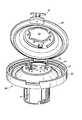
血漿生成物、血小板生成物及び赤血球生成物に全血を分離するように構成される分離バッグのセットが、図1に示されている。このセットは、分離バッグ1と3つの生成物バッグ2、3、4とを備える。分離バッグ1は、環状であり、外側円形エッジ5と内側円形エッジ6とを有する。分離バッグの変形が、内側エッジ6から外側エッジ5へ延出する1つ又は2つの壁を含み、そのために、バッグ内に画定されるチャンバは、環状である代わりに、C形状を有し、このCは多少開口する。さらに、分離バッグは、遠心分離機のロータの平坦なサポート表面、又は切頭円錐状サポート表面のいずれかに合うように形作られることが可能である。血漿生成物を含むように意図される第1の生成物バッグ2は、第1のチューブ7によって、分離バッグ1に、それの内側エッジ6で接続される。血小板生成物を含むように意図される第2の生成物バッグ3は、第2のチューブ8によって、分離バッグ1に、これの内側エッジ6で接続される。赤血球生成物を含むように意図される第3の生成物バッグ4は、第3のチューブ9によって、分離バッグ1に、これの内側エッジ6で接続される。これは、白血球減数フィルタ12(白血球を除去するフィルタ)の入口と出口とにそれぞれ接続される2つのセグメントを有するチューブ11によって、二次バッグ10に接続される。二次バッグ10は、多量の赤血球用貯蔵溶液を含む。二次バッグ10内から取り外し可能なプラグ13(例えば、いわゆる「脆いピン」)が、接続チューブ11を通る液体のフローをブロックして、この貯蔵溶液が第3の生成物バッグ4へ流動することを防止する。このバッグセットは、さらに、1つの端部において、分離バッグ1に、これの内側エッジで接続される供給チューブ14を備える。供給チューブ14のもう1つの端部は、多量の分離される血液がドナーから分離バッグ1へ直接取り出される場合、カニューレに接続されるか、又は、ドナーチューブ18(図1に示されるように)によって順番にカニューレ17に接続された収集バッグ16に、直接あるいは滅菌コネクタ15を介して接続されるかのいずれかである。ドナーからの多量の血液が直接移送されるバッグ(分離バッグ1又は収集バッグ16)は、多量の抗凝血溶液(一般に、約450mlの血液供血に対して約70mlのクエン酸ナトリウム液)を含む。 A set of separation bags configured to separate whole blood into plasma products, platelet products and red blood cell products is shown in FIG. This set comprises a separation bag 1 and three
図2は、分離バッグ1を示し、これは、狭い通路22を経由して内側半円形分配チャネル21と連絡する環状チャンバ20を画定する溶接線によって互いに結合される、軟質プラスチック材料の2枚の重ね合わせシートから作られる。より詳細には、環状チャンバ20は、外側エッジ5を形成する第1の円形溶接線と、内側エッジ6を形成する第2の円形溶接線とによって画定され、2つの円形線は、実質的に同軸である。分配チャネル21は、2つの実質的に平行かつ半円形の溶接線によって画定され、分配チャネル21の外側エッジ23と内側エッジ24とを形成する。環状チャンバの内側エッジ6及び分配チャネル21の外側エッジ24は、2つのポイントで結合して、それらの間に通路22を画定する。環状チャンバ20の内側エッジ6は、2つの連絡点の方へ向って内方に集中して、環状チャネル20の別の円形内側エッジ6の結果として生じる陥凹部は、通路22のちょうど上流側の環状チャンバ20内に三角形のベイエリア25を画定する。 FIG. 2 shows a separation bag 1, which consists of two pieces of soft plastic material joined together by a weld line defining an
通路22は、分配チャネル21において、チャネルの全長の約3分の2で開口する。通路22に関して、分配チャネル21は、その結果、相互に連結され、通路22から反対方向に延在する長いセグメントと小さいセグメントとを備えるように画定され得る。赤血球生成物用生成物バッグ4を分離チャンバ1に接続するチューブ9は、チャネル21の小さいセグメントに、その端部で接続される。血小板生成物用生成物バッグ3を分離チャンバ1に接続するチューブ8は、チャネル21の長いセグメントに、その端部で接続される。血漿生成物用生成物バッグ2を分離チャンバ1に接続するチューブ7は、チャネル21の長いセグメントに、これの全長の約2分の1で接続される。全血の源(ドナー又は収集バッグ16)を分離バッグ1に接続するチューブ14は、分配チャネル21の小さいセグメントが延在する方向と同じ方向に、通路22から内側エッジ6の周辺の約3分の1において、環状チャンバ1に、それの内側エッジ6で接続される。 The
分配チャネル21及びチューブ7、8、9、14の端部部分は、半硬質プラスチック材料の1枚のシートから作られるディスク形状サポート26に埋め込まれ、環状チャンバ20の内側エッジ6に、これの周辺で固定される。ディスク形状サポート26は、これの中間に大きいカットアウトと、分配チャネル21へのチューブ7、8、9の接続ポイントに隣接する3つの小さい円形カットアウト28、29、30とを備える。円形カットアウト28、29、30は、チューブ7、8、9の端部部分に対して位置決めされ、そのため各チューブは、対応する円形カットアウトの直径に沿って延在して、その結果、ディスク形状サポート26によってこれの全長の部分全体にわたりまっすぐに維持される。 The
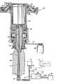
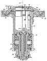
図3、図4及び図5は、遠心分離によって多量の混成液体を分離する装置を示す。この装置は、図1及び図2に示される分離バッグと生成物バッグとのセットを受容するように構成される遠心分離機と、分離バッグを圧搾して、分離された成分を生成物バッグへ移送させる圧搾システムとを備える。 3, 4 and 5 show an apparatus for separating a large amount of mixed liquid by centrifugation. The apparatus includes a centrifuge configured to receive the set of separation bag and product bag shown in FIGS. 1 and 2, and squeezing the separation bag to transfer the separated components to the product bag. And a pressing system for transport.
遠心分離機は、ベアリングアセンブリ33によって支持されるロータを備え、このロータが垂直中心軸34のまわりに回転することを可能にする。ロータは、円筒形ロータシャフト35、36と、ロータシャフト35、36の長手方向軸及びコンテナ37の長手方向軸がロータの中心軸34と一直線に並べられるように、このロータシャフト35、36にそれの上方端部で接続される円筒形コンテナ37と、ターンテーブル37の中心軸がロータの中心軸34と一直線に並べられるように、コンテナ37にそれの上方端部で接続される円形ターンテーブル38と、を備える。ロータシャフトは、第1の上方部分35と第2の下方部分36とを備える。シャフトの上方部分35は、一部はベアリングアセンブリ33を通って延在する。プーリ39は、シャフトの上方部分35の下方端部に接続される。 The centrifuge includes a rotor supported by a bearing
遠心分離機は、さらに、中心垂直軸34まわりにロータを回転するように、プーリ39の溝に係合されるベルト41によってロータに結合されるモータ40を備える。 The centrifuge further includes a
分離装置は、さらに、プラスチックチューブを通る流体のフローを選択的にブロックする、又は可能にして、プラスチックチューブを選択的に密閉及び中断するように、ロータに取り付けられる3つのピンチバルブ部材42、43、44を備える。各バルブ42、43、44は、細長い円筒形本体と、定置の上方ジョー及び開口位置と閉鎖位置との間を移動可能な下方ジョーによって画定される溝を有するヘッドとを備え、この溝は、下方ジョーが開口位置にあるとき、図1及び図2に示されるバッグセットのプラスチックチューブ7、8、9の1つが、その中に寄り添うように係合されることが可能なような大きさに作られる。細長い本体は、下方ジョーを動かすソレノイド始動メカニズムを含み、これは、プラスチックチューブを密閉及び中断するのに必要なエネルギーを供給する無線周波発電機に接続される。ピンチバルブ部材42、43、44は、円筒形コンテナ37の内側に、これの内部表面に隣接して取り付けられ、そのために、それらの長手方向軸は、ロータの中心軸34に平行であり、それらのヘッドは、コンテナ37のリムの上に突出する。図2に示される分離バッグ1のサポート部分26の3つの円形カットアウト28、29、30は、それを通る3つのピンチバルブ部材42、43、44のヘッドの係合を可能にするような大きさに作られて、位置決めされ、チューブ7、8、9の部分は、ピンチバルブ部材42、43、44のヘッドの溝に面するように方向付けられる、円形カットアウト28、29、30全体にわたり延在する。電力が、ロータシャフトの下方部分36まわりに取り付けられるスリップリング45を介してピンチバルブ部材42、43、44に供給される。 The separation device further includes three
ターンテーブル38は、上方の小さいエッジがコンテナ37のリムに接続される中心切頭円錐部分46と、切頭円錐部分46の下方の大きいエッジに接続される環状の平坦部分47と、環状部分47の外側周辺から上方に延在する外側円筒形フランジ48とを備える。ターンテーブル38は、さらに、開口位置と閉鎖位置との間を旋回するようにヒンジ50によってフランジ48に固定される、アーチ形天井の円形ふた49を備える。ふた49には、ロック51が装着され、これによって、ふたが閉鎖位置でブロックされることが可能である。ふた49は、これの上方部分に、ロータの円筒形コンテナ37にアクセスする大きいカットアウト52を備える。ふた49は、ふた49が閉鎖位置にあるとき、これが、ターンテーブル38の切頭円錐部分46と環状の平坦部分47とで、ほぼ平行四辺形の形状を有する径方向断面を有する切頭円錐環状区画53を画定するように形作られる、環状内部表面を有する。切頭円錐環状区画53は、以下「分離区画」とするが、図2に示される分離バッグの分離チャンバを含むように意図される。 The
分離区画53内で分離バッグを圧搾して、分離成分を生成物バッグへ移送させる圧搾システムは、ターンテーブル38の切頭円錐部分46と環状平坦部分47との内側を覆うように形作られるフレキシブルな環状ダイヤフラム54を備え、これは、これの小さい円形エッジと大きい円形エッジとに沿ってそれに固定される。圧搾システムは、さらに、ロータシャフトの下方部分36の下方端部からターンテーブル38へロータを延通するダクト55を経由して、フレキシブルなダイヤフラム54とターンテーブル38との間に画定される、拡張可能な液圧チャンバ32内外に作動液をポンプで注入する、液圧ポンプステーション31を備える。ポンプステーション31は、回転流体カプーリング58を経由してロータダクト55に流動的に接続される液圧シリンダ57内を移動可能なピストン56を有するピストンポンプを備える。ピストン56は、ピストンロッドにリンクされる親ねじ60を動かすステッパモータ59によって作動される。液圧シリンダ57は、さらに、液圧シリンダ57、ロータダクト55及び拡張可能な液圧チャンバ32を含む液圧回路へ、かつ、から作動液の導入又は回収を選択的に可能にするために、バルブ62によって制御されるアクセスを有する作動液貯蔵所61に接続される。圧力ゲージ63が、中の液圧を測定するために液圧回路に接続される。 The squeezing system for squeezing the separation bag in the
分離装置は、さらに、装置が作動するとき、分離バッグ内に生じる分離プロセスの特性を検知する3つのセンサ64、65、66を備える。3つのセンサ64、65、66は、ふた49が閉鎖されるとき、図2に示されるように分離バッグ1に面するようにふた49内に埋め込まれる。第1のセンサ64(以下、「チャネルセンサ」とする)は、分配チャネル21の長いセグメント全体にわたり位置決めされるように、ふた49内に埋め込まれる。チャネルセンサ64は、分配チャネル21内の液体の有無、液体中の赤血球を検知することとができる。第2のセンサ65(以下、「ベイセンサ」とする)は、ベイエリア25全体にわたり位置決めされるようにふた49内に埋め込まれる。ベイセンサ65は、液体中の赤血球を検知することができる。第3のセンサ66(以下、「バッグセンサ」とする)は、分配チャネル21の小さいセグメントの側のベイエリア25のわずかに外側に、分離チャンバ20の内側エッジ6から分離チャンバの全幅の約3分の1に、分離チャンバ20全体にわたり位置決めされるように、ふた49内に埋め込まれる。バッグセンサ66は、液体中の赤血球を検知することができる。各センサ64、65、66は、赤外線LEDと光検知器とを含む光電池を備えることが可能である。 The separation device further comprises three
分離装置は、さらに、マイクロプロセッサと、このマイクロプロセッサに、装置の作動に関する情報及びプログラムされた命令を供給するメモリとを含む、制御装置67を備える。特に、マイクロプロセッサは、ロータが分離プロセスの様々な段階の間に回転される様々な遠心分離速度に関する情報と、分離成分が分離バッグ1から生成物バッグ2、3、4へ移送される様々な移送流速に関する情報と、を受信するようにプログラムされる。様々な移送流速に関する情報は、例えば、液圧回路の作動液流速として、又は、液圧ポンプステーション31のステッパモータ59の回転速度として表示されることが可能である。マイクロプロセッサは、さらに、圧力ゲージ63からと、光電池64、65、66からとの情報を、直接又はメモリを介して受信するようにプログラムされる。 The separation device further comprises a
マイクロプロセッサは、さらに、分離装置を所定の分離プロトコルに沿って作動させるように、遠心分離機のモータ40と、ステッパモータ59と、ピンチバルブ部材42、43、44とを制御するように、プログラムされる。 The microprocessor is further programmed to control the
分離プロトコルの第1の例は、以下のとおりである。 A first example of a separation protocol is as follows.
第1段階:分離される多量の抗凝固血液は、使い捨てセットが以下の変形の1つにより遠心分離装置に装填される前又は後に、分離バッグへ移送される。 First stage: A large amount of anticoagulated blood to be separated is transferred to a separation bag before or after the disposable set is loaded into the centrifuge device by one of the following variants.
―第1の変形:分離される多量の抗凝固血液(例えば、約500ml)が、使い捨てセットが遠心分離装置に装着される前に、分離バッグへ移送される。クランプが分離バッグ1への各チューブ7、8、9の接続部に置かれた後、収集バッグ16に含まれる多量の抗凝固血液が、重力によって分離バッグ1へ移送される。収集バッグ16を分離バッグに接続するチューブ14は、密閉及び中断される。分離バッグ1は、ターンテーブル38内に装着され、チューブ7、8、9は、ピンチバルブ部材42、44、43に係合され、生成物バッグ2、3、4及び二次バッグ10は、コンテナ37へ置かれる。ピンチバルブ部材42、43、44は、閉鎖されて、チューブ7、8、9のクランプは、取り外される。別の方法として、分離装置の作動の間分離バッグ内で増加する圧力が脆いシ―ルを壊すほど十分に高くない限りは、生成物バッグ2、3、4と分離バッグ1との間の連通を防止するように、圧力に脆いシ―ルが分配チャネル21の両セグメントに設けられるとき、クランプはチューブ7、8、9に置かれない。 First variant: A large amount of anticoagulated blood to be separated (eg about 500 ml) is transferred to the separation bag before the disposable set is installed in the centrifuge. After the clamp is placed at the connection of each
―第2の変形:多量の抗凝血剤を含む分離バッグ1が、直接ドナーに接続されることと、ドナーの血液が、その後さらに収集バッグとして使用される分離バッグ1へ直接取り出されることとを除いては、第1の変形と同じである。 The second variant: the separation bag 1 containing a large amount of anticoagulant is connected directly to the donor, and the donor's blood is then taken directly into the separation bag 1 which is then used as a further collection bag; Is the same as the first modification.
第2段階:分離バッグ1に存在する空気は、赤血球成分が後に移送されることになる生成物バッグ4へ一掃される。 Second stage: The air present in the separation bag 1 is swept into the product bag 4 where the red blood cell component will be transferred later.
ピンチバルブ部材42、43は、閉鎖され、チューブ9が係合されるピンチバルブ部材44は、開口する。ロータは、遠心分離機のモータ40によって動くようにセットされ、これの回転速度は、これが第1の速い遠心分離速度(例えば、約3200RPM)で回転するまで確実に増加する。ロータが第1の遠心分離速度で回転する前に、ポンプステーション31は、一定の流速(例えば、約240ml/分)で、作動液を液圧チャンバ32へポンプで注入するように作動し、その結果として、分離バッグ1を圧搾する。分離バッグ1に存在する空気は、赤血球成分用生成物バッグ4へ排出される。チャネルセンサ64が分配チャネル21の液体を検知すると、ポンプステーション31は、停止され、ピンチバルブ部材44は、閉鎖される。 The
分離バッグ1の分配チャネル21が脆いシ―ルによって初めに閉鎖されるとき、分離バッグ1で増加する圧力が脆いシ―ルを壊させるほど十分に高くなると、分離バッグ1から生成物バッグ4へ空気が移送される。 When the
別の方法として、分離バッグ1に含まれる空気は、血漿成分用生成物バッグ2、又は血小板成分用生成物バッグ3のいずれかへ排出されることが可能であることに留意されたい。しかしながら、これにより、赤血球成分が後に、重力によって、生成物バッグ4から二次バッグ10へ移送されることを可能にするので、赤血球成分用バッグ4中の空気を排出することは興味深いことである。 Alternatively, it should be noted that the air contained in the separation bag 1 can be discharged to either the plasma
第3段階:分離チャンバ内の血液は、所望のレベルまで沈降される。 Third stage: The blood in the separation chamber is sedimented to a desired level.
この段階の始めに、3つのピンチバルブ部材42、43、44は、閉鎖される。ロータは、多量の血液のヘマトクリットが分離チャンバ1に初めに移送したとしても、血液は、外側の環状赤血球層のヘマトクリットが約90であり、かつ、内側の環状血漿層の血漿が実質的に細胞、赤血球層と血漿層との間の中間の環状層をその場合占める血小板と白血球を含まないポイントにまで、選択した周期の終わりに、その中に沈降するように選択される、所定の周期時間(例えば、約220秒)、第1の速い遠心分離速度(例えば、約3200RPM)で回転される。 At the beginning of this stage, the three
第4段階:第1の成分(血漿成分)が、生成物バッグ2へ移送される。 Fourth stage: The first component (plasma component) is transferred to the
この段階の始めに、3つのピンチバルブ部材42、43、44は、閉鎖される。第4段階を通して、ロータは、第1の速い遠心分離速度(例えば、3200RPM)で回転される。所定の沈降周期が終わる前に起こり得る、バッグセンサ66が赤血球の検知を停止した後の所定の周期時間後、血漿成分バッグ2へのアクセスを制御するピンチバルブ部材42は、開口され、ポンプステーション31は、一定の流速(例えば、約220ml/分)で、作動液を液圧チャンバ32へポンプで注入するように作動され、その結果として、血漿の第1の部分を生成物バッグ2へ移送させるように分離バッグ1を圧搾するのに対して、血漿の第2の部分(例えば、約60ml)が、分離バッグ1にとどまる。ポンプステーション31は、バッグセンサ66が赤血球を検知した後、所定の周期時間が経過したときに停止される。 At the beginning of this stage, the three
血漿成分の移送流速(作動液の流速に直接関連する)は、血漿成分を血小板で汚染することを回避するように血小板層をかき乱すことなく、できる限り速いように選択される。 The plasma component transport flow rate (directly related to the working fluid flow rate) is selected to be as fast as possible without disturbing the platelet layer to avoid contaminating the plasma component with platelets.
第5段階:中間成分(血小板成分)が、分離バッグ1で準備される。 Fifth stage: An intermediate component (platelet component) is prepared in the separation bag 1.
―第1の変形:血小板成分バッグ3へのアクセスを制御するピンチバルブ部材43は、開口され、ピンチバルブ部材42、44は、閉鎖される。ロータの回転速度は、血漿の第2の部分への血小板の懸濁の結果として生じる中間成分を形成するように、第1の遠心分離速度から第2の遠心分離速度(例えば、約10秒内に、約3200RPMへ約2000RPM)へ迅速に減速されるのに対して、赤血球層及び懸濁血小板層は、実質的に分離されたままである。 First variant: The
―第2の変形:3つのピンチバルブ部材42、43、44は、閉鎖される。ロータの回転速度は、赤血球と、血小板と、血漿の第2の部分とを混合するように、第1の遠心分離速度から第2の遠心分離速度へ(例えば、約20秒内に、約3200RPMから約1000RPMへ)迅速に減速される。ロータの回転速度は、次に、分離バッグ1で赤血球成分と、血漿中に血小板の懸濁液を備える中間成分とを分離するように、第2の遠心分離速度から、第1の遠心分離速度よりも遅い第3の遠心分離速度へ(例えば、約1000RPMから約2500RPMへ)加速される。 Second variant: the three
第6段階:中間成分(血小板成分)は、生成物バッグ3へ移送される。 Sixth stage: The intermediate component (platelet component) is transferred to the product bag 3.
血小板成分バッグ3へのアクセスを制御するピンチバルブ部材43は、開口され、ピンチバルブ部材42、44は、閉鎖される。ロータは、第2の遠心分離速度(例えば、先行段階が第5段階の第1の変形である場合、約2000RPM)又は第3の回転速度(例えば、先行段階が第5段階の第2の変形である場合、約2500RPM)で回転される。ポンプステーション31は、第1の流速で、作動液を液圧チャンバ32へポンプで注入するように作動され、その結果として、分離バッグ1を圧搾し、血小板成分を生成物バッグ3へ移送させる。第1の流速(例えば、約140ml/分)は、血漿成分が第4段階で生成物バッグ2へ移送される流速(例えば、約220ml/分)より実質的に遅い。血小板成分の第1の移送流速(作動液の第1の流速に直接関連する)は、血小板の活性化を同時にトリガすることなく、懸濁された血小板が沈降することを防止するのに十分に速いように選択される。 The
ベイセンサ65が赤血球を検知するとき、ポンプステーション31は、赤血球による血小板成分の汚染を防止するために、第1の流速より実質的に遅い第2の流速(例えば、40ml/分)で、作動液を液圧チャンバ32へポンプで注入するように作動される。 When the
作動液が所定の周期時間(例えば、約4秒)、第2の流速で液圧チャンバ32へポンプで注入されたとき、ポンプステーションは、チャネルセンサ64が赤血球を検知した後、所定の周期時間(例えば、約12秒)が経過するまで、第2の流速より遅い第3の流速(例えば、約20ml/分)で作動液をポンプで注入するように作動される。ポンプステーション31は、次に、停止される。 When hydraulic fluid is pumped into the
第7段階:第3の成分(赤血球成分)は、生成物バッグ4へ移送される。 Seventh stage: The third component (red blood cell component) is transferred to the product bag 4.
赤血球成分バッグ4へのアクセスを制御するピンチバルブ部材44は、開口され、ピンチバルブ部材42、43は、閉鎖される。ロータの回転速度は、第2の遠心分離速度(例えば、約2000RPM)又は第3の遠心分離速度(例えば、約2500RPM)から、第4の遅い遠心分離速度(例えば、約1500RPM)へ減速される。ポンプステーション31は、第1の流速で、作動液を液圧チャンバ32へポンプで注入するように作動され、その結果として、赤血球成分を生成物バッグ4へ移送させるように、分離バッグ1を圧搾する。第1の流速(例えば、約350ml/分)は、血漿成分が第4段階で生成物バッグ2へ移送される流速(例えば、約220ml/分)より実質的に速い。赤血球成分の第1の移送流速(作動液の流速に直接関連する)は、赤血球を損傷する(溶血現象)ことなく、できる限り速いように選択される。 The
圧力ゲージ63によって測定される作動液の圧力が第1の高い圧力しきい値(例えば、約0.7バール)に達するとき、作動液の流速は、第1の流速から第2の流速(例えば、約100ml/分)へ減速される。 When the hydraulic fluid pressure measured by the
圧力ゲージ63によって測定される作動液の圧力が第2の高い圧力しきい値(例えば、約1.6バール)に達するとき、作動液の流速は、第2の流速から第3の流速(例えば、約37ml/分)へさらに減速される。 When the hydraulic fluid pressure measured by the
赤血球成分の第2の移送流速及び第3の移送流速(作動液の流速に直接関連する)は、赤血球成分の最大部分が赤血球成分バッグ4へ移送されるように選択される。 The second transfer flow rate and the third transfer flow rate (related directly to the flow rate of the working fluid) of the red blood cell component are selected such that the largest part of the red blood cell component is transferred to the red blood cell component bag 4.
作動液の圧力が第2の圧力しきい値に達した後所定の周期時間(例えば、約30秒)が経過したとき、ロータの回転速度は、ロータが停止するまで減速され、ポンプステーション31は、液圧チャンバ32が空になるまで速い流速(例えば、約800ml/分)で液圧チャンバ32から作動液をポンプで吸い上げるように作動されて、3つのピンチバルブ部材42、43、44は、チューブ7、8、9を密閉及び中断するように作動される。 When a predetermined period of time (eg, about 30 seconds) elapses after the hydraulic fluid pressure reaches the second pressure threshold, the rotational speed of the rotor is reduced until the rotor stops, and the
血漿成分用の少なくとも1つの第1の移送流速(上述の例の1つの流速)、血小板成分用の少なくとも1つの第2の移送流速(上述の例の3つの連続的流速)、赤血球成分用の少なくとも1つの第3の流速(上述の例の3つの連側的流速)のうちいずれかは、上述の例のように、ほぼ一定でよく、又は変化してもよく、例えば、ランプ又は一連の小さいステップを備えることもできる。 At least one first transfer flow rate for plasma components (one flow rate in the above example), at least one second transfer flow rate for platelet components (three consecutive flow rates in the above example), for red blood cell components Any of the at least one third flow rate (the three continuous flow rates in the above example) may be substantially constant, as in the above example, or may vary, eg, a ramp or a series of Small steps can also be provided.
分離プロトコルの第2の例によれば、多量の血液が、4つの成分、すなわち血漿成分と、第1の中間成分(血漿中に懸濁される血小板を備える)と、第2の中間成分(白血球の2つのタイプのうち1つ、すなわち単核球を備える)と、赤血球成分とに分離される。 According to a second example of the separation protocol, a large amount of blood is divided into four components: a plasma component, a first intermediate component (comprising platelets suspended in plasma), and a second intermediate component (white blood cells). One of the two types, i.e. comprising mononuclear cells) and the red blood cell component.
この第2の分離プロトコルでは、血小板成分を血小板バッグへ移送する段階の後、単核球は、特定の単核球バッグか、又は、全血収集バッグかのいずれかへ移送され、それはこの場合、多量の抗凝固血液を収集バッグから分離バッグへ移送する初期段階の後、分離バッグから断絶されない。単核球は、血小板の移送と同じ回転速度(例えば、約2500RPM)で、血小板の第3の移送流速及び最終移送流速(例えば、約20ml/分)より速い移送速度(例えば、約40ml/分)で移送される。単核球成分の移送は、所定の周期時間が経過後完了される。 In this second separation protocol, after transferring the platelet component to the platelet bag, the mononuclear cells are transferred to either a specific mononuclear cell bag or a whole blood collection bag, which in this case After the initial stage of transferring a large amount of anticoagulated blood from the collection bag to the separation bag, it is not disconnected from the separation bag. Mononuclear cells have a transfer rate (eg, about 40 ml / min) that is faster than the third and final transfer flow rates (eg, about 20 ml / min) of platelets at the same rotational speed (eg, about 2500 RPM) as platelet transfer. ). The transfer of the mononuclear cell component is completed after a predetermined period of time has elapsed.
第2の分離プロトコルによれば、単核球成分を単核球バッグへ移送する段階の後、分離バッグにとどまる赤血球は、遠心分離機が停止して、分離バッグが遠心分離機から取り外された後、重力によって赤血球バッグへ移送される。この第2のプロトコルに適用されるバッグのセットでは、赤血球バッグは、分離バッグの外側エッジで接続されることが好ましい。上述のバッグのセットが使用される場合、分離プロセスの初めに分離バッグに存在する空気は、その場合、分離バッグの内側エッジに接続される成分バッグの1つに、例えば単核球バッグに排出される。 According to the second separation protocol, after transferring the mononuclear cell component to the mononuclear bag, red blood cells that remain in the separation bag were stopped by the centrifuge and the separation bag was removed from the centrifuge. Later, it is transferred to the red blood cell bag by gravity. In the set of bags applied to this second protocol, the red blood cell bags are preferably connected at the outer edge of the separation bag. If the set of bags described above is used, the air present in the separation bag at the beginning of the separation process is then discharged into one of the component bags connected to the inner edge of the separation bag, for example into a mononuclear cell bag Is done.
分離プロトコルの第3の例によれば、多量の血液が、3つの成分、すなわち血漿成分と、中間成分(血小板と単核球を備える)と、赤血球成分とに分離される。 According to a third example of the separation protocol, a large amount of blood is separated into three components: a plasma component, an intermediate component (comprising platelets and mononuclear cells), and a red blood cell component.
多量の抗凝固血液が所望のレベルにまで沈降したとき、血漿成分の主要部分は、最大流速(例えば、約220ml/分)で血漿バッグへ移送される。血漿の移送は、赤血球が、分離バッグに残るように望まれる血漿の残留容量により、バッグセンサ66によって、又はベイセンサ65によって検知された後、決定された周期時間が経過した後停止される。中間成分(残留血漿、血小板、単核球及び多少の赤血球)は、次に、特定の成分バッグ又は全血収集バッグ16のいずれかあってよい、中間成分バッグへ移送される。血小板/単核球成分は、血漿の移送と同じ回転速度(例えば、約3200RPM)で、さらに、一定移送流速だが、血漿の移送流速より遅い流速(例えば、約140ml/分)で、移送される。血小板/単核球成分の移送は、所定の容量が中間成分バッグへ絞り出された後完了される。 When a large amount of anticoagulated blood settles to the desired level, the major portion of the plasma component is transferred to the plasma bag at the maximum flow rate (eg, about 220 ml / min). Plasma transfer is stopped after a determined period of time has elapsed after red blood cells are detected by the
第3の分離プロトコルでは、血小板/単核球成分を中間成分バッグへ移送する段階の後、分離バッグにとどまる赤血球は、遠心分離機が停止して、分離バッグが遠心分離機から取り外された後、重力によって赤血球バッグへ移送される。 In the third separation protocol, after transferring the platelet / mononuclear cell component to the intermediate component bag, red blood cells remaining in the separation bag are removed after the centrifuge is stopped and the separation bag is removed from the centrifuge. , Transferred to the red blood cell bag by gravity.
分離プロトコルの第4の例によれば、多量の血液が、2つの成分、すなわち血漿成分と細胞成分(血小板、白血球及び赤血球)に分離される。分離バッグの適切なセットが、唯一の成分(血漿)バッグに接続される分離バッグを備えてよい。 According to a fourth example of the separation protocol, a large amount of blood is separated into two components: a plasma component and a cellular component (platelet, white blood cell and red blood cell). A suitable set of separation bags may comprise a separation bag connected to a single component (plasma) bag.
この第4の分離プロトコルでは、分離バッグ1に初めに存在する空気は、血漿バッグに排出される。多量の抗凝固血液が所望のレベルにまで沈降したとき、血漿成分が、2つの異なる速度で血漿バッグへ移送される。血漿の主要部分が、最大流速で移送され、血漿の残りの部分は、次に、遅い流速で移送される。第2の流速は、血漿の最大容量が血漿バッグへ移送され、血球による血漿の汚染が回避されるように選択される。細胞成分は、遠心分離機が停止した後さらに処理するために、分離バッグにとどまる。 In this fourth separation protocol, the air initially present in the separation bag 1 is discharged into the plasma bag. When a large amount of anticoagulated blood settles to the desired level, plasma components are transferred to the plasma bag at two different rates. The main part of the plasma is transferred at the maximum flow rate and the remaining part of the plasma is then transferred at the slow flow rate. The second flow rate is selected such that the maximum volume of plasma is transferred to the plasma bag and plasma contamination with blood cells is avoided. Cell components remain in the separation bag for further processing after the centrifuge has stopped.
様々な変更がここに説明される装置及び方法に行われ得ることは、当業者には明らかである。したがって、本発明は、明細書に論じられる内容に制限されるものではないことを理解されたい。むしろ、本発明は、変更例及び変形例を包含するように意図される。 It will be apparent to those skilled in the art that various modifications can be made to the devices and methods described herein. Accordingly, it should be understood that the invention is not limited to what is discussed in the specification. Rather, the present invention is intended to cover modifications and variations.
Claims (25)
Translated fromJapanese前記分離バッグ(1)をスピンするロータ(35、36、37、38)を有する、遠心分離機と、
前記分離バッグ(1)を圧搾して、前記分離バッグ(1)から前記第1の成分バッグ(2)へ前記第1の成分の少なくとも1つの部分を移送させ、かつ、前記分離バッグ(1)から前記中間成分バッグ(3)へ前記中間成分を移送させる、圧搾部材(31、54、55)と、
前記分離バッグ(1)内への前記少なくとも第1の成分と第2の成分と第3の成分との沈降を可能にする少なくとも1つの遠心分離速度と、前記第1の成分バッグ(2)への前記第1の成分の少なくとも1つの第1の移送流速及び前記中間成分バッグ(3)への前記中間成分の少なくとも1つの第2の移送流速に関する情報とを格納する、メモリであり、それによって、前記少なくとも1つの第1の移送流速及び前記少なくとも1つの第2の移送流速は異なる、メモリと、
前記少なくとも1つの遠心分離速度と、前記少なくとも1つの第1の移送流速及び前記少なくとも1つの第2の移送流速に関する情報とを、前記メモリから受信するように、
前記ロータ(35、36、37、38)を前記少なくとも1つの遠心分離速度で回転させるように、
前記分離バッグ(1)内に前記少なくとも第1の成分と第2の成分と第3の成分とが沈降後、前記少なくとも1つの第1の移送流速で前記分離バッグ(1)から前記第1の成分バッグ(2)へ前記第1の成分の前記少なくとも1つの部分を移送するように、かつ、前記少なくとも1つの第2の移送流速で前記分離バッグ(1)から前記中間成分バッグ(3)へ前記中間成分を移送するように、前記圧搾部材(31、54、55)に前記分離バッグ(1)を圧搾させるように、
さらに、前記分離バッグ(1)内に前記少なくとも第1の成分と第2の成分と第3の成分とが沈降時、前記少なくとも1つの第1の移送流速で前記分離バッグ(1)から前記第1の成分バッグ(2)へ前記第1の成分の第1の部分を移送するように、前記圧搾部材(31、54、55)に前記分離バッグ(1)を圧搾させるのに対して、前記第1の成分の第2の部分が、前記分離バッグ(1)内にとどまるように、
前記第1の成分バッグ(2)へ前記第1の成分の前記第1の部分を移送後、前記第2の成分を前記第1の成分の前記第2の部分と混合して、前記中間成分を形成するように、前記遠心分離速度を変化させるように、
プログラムされる制御ユニット(67)と、
を備える、装置。An apparatus for separating a large amount of mixed liquid into at least a first component, an intermediate component including a second component, and a third component, wherein the large amount of mixed liquid is at least a first component bag (2 ) And the intermediate component bag (3) included in the soft separation bag (1), the device comprising:
A centrifuge having a rotor (35, 36, 37, 38) for spinning the separation bag (1);
Squeezing the separation bag (1) to transfer at least one portion of the first component from the separation bag (1) to the first component bag (2), and to the separation bag (1) A pressing member (31, 54, 55) for transferring the intermediate component from the intermediate component bag (3) to the intermediate component bag (3);
At least one centrifuge speed allowing sedimentation of the at least first component, second component and third component into the separation bag (1), and to the first component bag (2). A memory for storing at least one first transfer flow rate of said first component and information relating to at least one second transfer flow rate of said intermediate component to said intermediate component bag (3), thereby The memory wherein the at least one first transfer flow rate and the at least one second transfer flow rate are different;
Receiving from the memory the at least one centrifugation speed and information about the at least one first transfer flow rate and the at least one second transfer flow rate;
Rotating the rotor (35, 36, 37, 38) at the at least one centrifuge speed;
After the at least first component, the second component, and the third component settle in the separation bag (1), the first bag from the separation bag (1) at the at least one first transfer flow rate. In order to transfer the at least one portion of the first component to the component bag (2) and at the at least one second transfer flow rate from the separation bag (1) to the intermediate component bag (3). To squeeze the separation bag (1) to the squeezing member (31, 54, 55) so as to transfer the intermediate component,
Further, when the at least first component, the second component, and the third component settle in the separation bag (1), the separation bag (1) moves from the separation bag (1) at the first transfer flow rate. Whereas the squeezing member (31, 54, 55) squeezes the separation bag (1) so as to transfer the first part of the first component to one component bag (2), So that the second part of the first component remains in the separation bag (1),
After transferring the first portion of the first component to the first component bag (2), the second component is mixed with the second portion of the first component and the intermediate component So as to change the centrifugation speed so as to form
A control unit (67) to be programmed;
An apparatus comprising:
前記第1のセンサ(64)の上流側の前記中間成分バッグ(3)への流体の経路の前記第3の成分を検知する、第2のセンサ(65)と、
をさらに備える装置であって、
前記制御ユニット(67)は、さらに、前記第1のセンサ(64)と前記第2のセンサ(65)とから情報を受信して、前記第1のセンサ(64)が前記第3の成分を検知するまで前記初期流速で、かつ、前記第2のセンサ(65)が前記第3の成分を検知するとき前記最終流速で、前記中間成分を移送させるようにプログラムされる、請求項3に記載の装置。A first sensor (64) for detecting the third component of the fluid path to the intermediate component bag (3);
A second sensor (65) for detecting the third component of the fluid path to the intermediate component bag (3) upstream of the first sensor (64);
A device further comprising:
The control unit (67) further receives information from the first sensor (64) and the second sensor (65), and the first sensor (64) receives the third component. 4. The intermediate component is programmed to transfer at the initial flow rate until detection and at the final flow rate when the second sensor (65) detects the third component. Equipment.
前記分離バッグ(1)を前記中間成分バッグ(3)に接続する第2のチューブ(8)と相互に作用して、それを通る流体のフローを選択的に可能にする、又はブロックするように、前記ロータ(35、36、37、38)に取り付けられる、第2のバルブ部材(43)と、
をさらに備える装置であって、
前記制御ユニット(67)は、さらに、前記第2の成分と前記第1の成分の前記第2の部分との混合及び前記中間成分の前記形成の間、前記第1のバルブ部材(42)を閉鎖させて、前記第2のバルブ部材(43)を開口させるようにプログラムされる、請求項6に記載の装置。The separation bag (1) interacts with a first tube (7) connecting to the first component bag (2) to selectively allow or block the flow of fluid therethrough. A first valve member (42) attached to the rotor (35, 36, 37, 38);
Interacting with the second tube (8) connecting the separation bag (1) to the intermediate component bag (3) to selectively allow or block the flow of fluid therethrough A second valve member (43) attached to the rotor (35, 36, 37, 38);
A device further comprising:
The control unit (67) further moves the first valve member (42) during the mixing of the second component and the second portion of the first component and the formation of the intermediate component. 7. The device according to claim 6, programmed to close and open the second valve member (43).
前記第1の成分バッグ(2)へ前記第1の成分の前記第1の部分を移送後、前記第2の成分と前記第1の成分の前記第2の部分及び前記第3の成分とを混合させるように、第1の遠心分離速度から第2の遠心分離速度へ前記遠心分離速度を迅速に減速させるように、
前記第2の成分と前記第1の成分の前記第2の部分及び前記第3の成分とを混合後、前記第2の成分と前記第1の成分の前記第2の部分とを備える中間成分から前記第3の成分を分離するように、前記第2の遠心分離速度から第3の遠心分離速度へ前記遠心分離速度を加速させるように、
プログラムされる、請求項1に記載の装置。The control unit (67) further comprises:
After transferring the first portion of the first component to the first component bag (2), the second component, the second portion of the first component, and the third component. So as to rapidly reduce the centrifuge speed from the first centrifuge speed to the second centrifuge speed so as to mix.
An intermediate component comprising the second component and the second portion of the first component after mixing the second component, the second portion of the first component and the third component Accelerating the centrifuge speed from the second centrifuge speed to a third centrifuge speed so as to separate the third component from
The apparatus of claim 1 programmed.
前記分離バッグ(1)を前記中間成分バッグに接続する第2のチューブ(8)と相互に作用して、それを通る流体のフローを選択的に可能にする、又はブロックするように、前記ロータ(35、36、37、38)に取り付けられる、第2のバルブ部材(43)と、
をさらに備える装置であって、
前記制御ユニット(67)は、さらに、第1の遠心分離速度から第2の遠心分離速度へ前記遠心分離速度を迅速に減速させる前に、前記第1のバルブ部材(42)と前記第2のバルブ部材(43)とを閉鎖させるようにプログラムされる、請求項8に記載の装置。The separation bag (1) interacts with a first tube (7) connecting to the first component bag (2) to selectively allow or block the flow of fluid therethrough. A first valve member (42) attached to the rotor (35, 36, 37, 38);
The rotor to interact with the second tube (8) connecting the separation bag (1) to the intermediate component bag to selectively allow or block the flow of fluid therethrough. A second valve member (43) attached to (35, 36, 37, 38);
A device further comprising:
The control unit (67) further includes the first valve member (42) and the second valve before rapidly reducing the centrifugal speed from a first centrifugal speed to a second centrifugal speed. Device according to claim 8, programmed to close the valve member (43).
前記センサ(66)から情報を受信するように、
前記遠心分離速度が前記第2の回転速度から前記第3の回転速度へ加速された後、前記センサ(66)がそれ以上前記第3の成分を検知しないとき、前記第2のバルブ部材(43)を開口させて、前記圧搾部材(31、54、55)に前記分離バッグ(1)から前記中間成分バッグ(3)へ前記中間成分を移送させるように、
プログラムされる、請求項9に記載の装置。The apparatus further comprising a sensor (66) for detecting the third component of the fluid path to the intermediate component bag (3), the control unit (67) further comprising:
To receive information from the sensor (66),
When the sensor (66) no longer detects the third component after the centrifugal speed is accelerated from the second rotational speed to the third rotational speed, the second valve member (43 ) Is opened, and the intermediate component is transferred from the separation bag (1) to the intermediate component bag (3) by the pressing member (31, 54, 55).
The apparatus of claim 9, which is programmed.
前記分離バッグ(1)を前記中間成分バッグ(3)に接続する第2のチューブ(8)と相互に作用して、それを通る流体のフローを選択的に可能にする、又はブロックするように、前記ロータ(35、36、37、38)に取り付けられる、第2のバルブ部材(43)と、
前記第1の成分バッグ(2)への流体の経路の前記第3の成分を検知する、センサ(66)と、
をさらに備える装置であって、
前記制御ユニット(67)は、さらに、前記センサ(66)から情報を受信するように、かつ、前記第1のバルブ部材(42)と前記第2のバルブ部材(43)とを制御するようにプログラムされる、請求項1に記載の装置。The separation bag (1) interacts with a first tube (7) connecting to the first component bag (2) to selectively allow or block the flow of fluid therethrough. A first valve member (42) attached to the rotor (35, 36, 37, 38);
Interacting with the second tube (8) connecting the separation bag (1) to the intermediate component bag (3) to selectively allow or block the flow of fluid therethrough A second valve member (43) attached to the rotor (35, 36, 37, 38);
A sensor (66) for sensing the third component of the fluid path to the first component bag (2);
A device further comprising:
The control unit (67) is further configured to receive information from the sensor (66) and to control the first valve member (42) and the second valve member (43). The apparatus of claim 1 programmed.
前記第1のバルブ部材(42)を開口させることによって、
前記第2のバルブ部材(43)を閉鎖させることによって、
前記第1の成分バッグ(2)への流体の経路の前記センサ(66)が前記第1の成分バッグ(2)への流体の経路の前記第3の成分を検知するまで、前記圧搾部材(31、54、55)に前記分離バッグ(2)を圧搾させることによって、
前記分離バッグ(1)から前記第1の成分バッグ(2)へ、前記第1の成分の前記少なくとも1つの部分を移送させるようにプログラムされる、請求項11に記載の装置。The control unit (67) further comprises:
By opening the first valve member (42),
By closing the second valve member (43),
Until the sensor (66) of the fluid path to the first component bag (2) detects the third component of the fluid path to the first component bag (2), the pressing member ( 31, 54, 55) by squeezing the separation bag (2),
12. Apparatus according to claim 11, programmed to transfer the at least one portion of the first component from the separation bag (1) to the first component bag (2).
第2のバルブ部材(43)を開口させることによって、
第1のバルブ部材(42)を閉鎖させることによって、
前記第1のセンサ(64)が前記中間成分バッグへの流体の経路の前記第3の成分を検知するまで、前記圧搾部材(31、54、55)に前記分離バッグ(1)を圧搾させることによって、
前記分離バッグ(1)から前記中間成分バッグへ、前記中間成分を移送させるようにプログラムされる、請求項13に記載の装置。The control unit (67) is further
By opening the second valve member (43),
By closing the first valve member (42),
Squeezing the separation bag (1) to the squeeze member (31, 54, 55) until the first sensor (64) detects the third component of the fluid path to the intermediate component bag. By
14. Apparatus according to claim 13, programmed to transfer the intermediate component from the separation bag (1) to the intermediate component bag.
前記メモリは、さらに、前記第3の成分バッグ(4)への前記第3の成分の少なくとも1つの第3の移送流速に関する情報を格納するためのものであり、それによって、前記少なくとも1つの第3の移送流速は、前記少なくとも1つの第2の移送流速と異なり、
前記制御ユニット(67)は、さらに、
前記少なくとも1つの第3の移送流速に関する前記情報を前記メモリから受信するように、
前記少なくとも1つの第3の移送流速で、前記分離バッグ(1)から前記第3の成分バッグ(4)へ前記第3の成分を移送するように、前記圧搾部材(31、54、55)に前記分離バッグ(1)を圧搾させるように、
プログラムされる、請求項1に記載の装置。The pressing member (31, 54, 55) is for transferring the third component to a third component bag (4) connected to the separation bag (1),
The memory is further for storing information relating to at least one third transfer flow rate of the third component to the third component bag (4), whereby the at least one first component bag (4). 3 is different from the at least one second transfer flow rate,
The control unit (67) further comprises:
Receiving the information from the memory about the at least one third transfer flow rate;
The squeezing member (31, 54, 55) is adapted to transfer the third component from the separation bag (1) to the third component bag (4) at the at least one third transfer flow rate. To squeeze the separation bag (1),
The apparatus of claim 1 programmed.
前記分離バッグ(1)を前記中間成分バッグ(3)に接続する第2のチューブ(8)と相互に作用して、それを通る流体のフローを選択的に可能にする、又はブロックするように、前記ロータ(35、36、37、38)に取り付けられる、第2のバルブ部材(43)と、
前記分離バッグ(1)を前記第3の成分バッグ(4)に接続する第3のチューブ(9)と相互に作用して、それを通る流体のフローを選択的に可能にする、又はブロックするように、前記ロータ(35、36、37、38)に取り付けられる、第3のバルブ部材(44)と、
をさらに備える装置であって、
前記制御ユニット(67)は、さらに、前記第1のバルブ部材(42)と前記第2のバルブ部材(43)と前記第3のバルブ部材(44)とを制御するようにプログラムされる、請求項16から18のいずれか1項に記載の装置。The separation bag (1) interacts with a first tube (7) connecting to the first component bag (2) to selectively allow or block the flow of fluid therethrough. A first valve member (42) attached to the rotor (35, 36, 37, 38);
Interacting with the second tube (8) connecting the separation bag (1) to the intermediate component bag (3) to selectively allow or block the flow of fluid therethrough A second valve member (43) attached to the rotor (35, 36, 37, 38);
The separation bag (1) interacts with a third tube (9) that connects to the third component bag (4) to selectively allow or block the flow of fluid therethrough. A third valve member (44) attached to the rotor (35, 36, 37, 38);
A device further comprising:
The control unit (67) is further programmed to control the first valve member (42), the second valve member (43), and the third valve member (44). Item 19. The apparatus according to any one of Items 16 to 18.
前記第3のバルブ部材(44)を開口させることによって、
前記第1のバルブ部材(42)と前記第2のバルブ部材(43)とを閉鎖させることによって、
分離バッグが実質的に空になるまで、前記圧搾部材(31、54、55)に前記分離バッグ(1)を圧搾させることによって、
前記分離バッグ(1)から前記第3の成分バッグへ前記第3の成分を移送させるようにプログラムされる、請求項19に記載の装置。The control unit (67) further comprises:
By opening the third valve member (44),
By closing the first valve member (42) and the second valve member (43),
By squeezing the separation bag (1) to the pressing member (31, 54, 55) until the separation bag is substantially empty,
20. Apparatus according to claim 19, programmed to transfer the third component from the separation bag (1) to the third component bag.
前記分離バッグ(1)を支持するターンテーブル(38)と、
前記軟質分離バッグ(1)を囲むように前記ターンテーブル(38)に固定されることが可能なふた(49)と、
を備える装置であって、
前記圧搾部材(31、54、55)は、
前記ターンテーブル(38)に固定されるフレキシブルなダイヤフラム(54)と、
前記ターンテーブル(38)と前記フレキシブルなダイヤフラム(54)との間に境界が定められる拡張可能なチャンバ(32)の内外に、作動液をポンプで注入するポンプステーション(31)であり、それによって、前記軟質分離バッグ(1)は、前記作動液が前記拡張可能なチャンバ(32)へポンプで注入されるとき、前記ふた(49)に圧搾される、ポンプステーション(31)と、
前記作動液の圧力を感知する圧力センサ(63)であり、前記分離バッグ(1)が実質的に空であるときを検知する前記空状態センサは、前記圧力センサである、圧力センサ(63)と、
を備える、請求項21に記載の装置。The rotor (35, 36, 37, 38)
A turntable (38) for supporting the separation bag (1);
A lid (49) that can be secured to the turntable (38) so as to surround the soft separation bag (1);
A device comprising:
The pressing members (31, 54, 55)
A flexible diaphragm (54) fixed to the turntable (38);
A pump station (31) for pumping hydraulic fluid into and out of an expandable chamber (32) delimited between the turntable (38) and the flexible diaphragm (54), thereby The soft separation bag (1) comprises a pump station (31), which is squeezed into the lid (49) when the hydraulic fluid is pumped into the expandable chamber (32);
A pressure sensor (63) that senses the pressure of the hydraulic fluid, and the empty state sensor that senses when the separation bag (1) is substantially empty is the pressure sensor. When,
The apparatus of claim 21, comprising:
前記第1のバルブ部材(42)と前記第2のバルブ部材(43)とを閉鎖させることによって、
前記第3のバルブ部材(44)を開口させることによって、
前記第1のセンサ(64)が前記第1の成分を検知するまで、前記圧搾部材(31、54、55)に前記分離バッグ(1)を圧搾させることによって、
前記センサ(64)から情報を受信するように、かつ、前記分離バッグ(1)から前記第3の成分バッグへ空気を移送させるようにプログラムされる、請求項19から23のいずれか1項に記載の装置。A device further comprising a sensor (64) for detecting fluid in a path from the separation bag (1) to the third component bag (4), wherein the control unit (67) further comprises:
By closing the first valve member (42) and the second valve member (43),
By opening the third valve member (44),
By squeezing the separation bag (1) to the pressing member (31, 54, 55) until the first sensor (64) detects the first component,
24. According to any one of claims 19 to 23, programmed to receive information from the sensor (64) and to transfer air from the separation bag (1) to the third component bag. The device described.
Applications Claiming Priority (3)
| Application Number | Priority Date | Filing Date | Title |
|---|---|---|---|
| US54663704P | 2004-02-20 | 2004-02-20 | |
| US60/546,637 | 2004-02-20 | ||
| PCT/US2005/004252WO2005082540A1 (en) | 2004-02-20 | 2005-02-10 | Apparatus and method for separating a volume of composite liquid into at least two components |
Publications (2)
| Publication Number | Publication Date |
|---|---|
| JP2007522875A JP2007522875A (en) | 2007-08-16 |
| JP4938465B2true JP4938465B2 (en) | 2012-05-23 |
Family
ID=34710275
Family Applications (1)
| Application Number | Title | Priority Date | Filing Date |
|---|---|---|---|
| JP2006554136AExpired - Fee RelatedJP4938465B2 (en) | 2004-02-20 | 2005-02-10 | Apparatus and method for separating a large amount of hybrid liquid into at least two components |
Country Status (10)
| Country | Link |
|---|---|
| EP (2) | EP2210629B1 (en) |
| JP (1) | JP4938465B2 (en) |
| KR (1) | KR101188482B1 (en) |
| CN (1) | CN100593438C (en) |
| AT (1) | ATE554808T1 (en) |
| AU (1) | AU2005216883A1 (en) |
| BR (1) | BRPI0507183A (en) |
| CA (1) | CA2553997A1 (en) |
| ES (2) | ES2565513T3 (en) |
| WO (1) | WO2005082540A1 (en) |
Families Citing this family (21)
| Publication number | Priority date | Publication date | Assignee | Title |
|---|---|---|---|---|
| EP2206527B1 (en) | 2006-09-06 | 2016-01-27 | Terumo BCT, Inc. | Apparatus and method for separating a composite liquid into at least two components |
| WO2008140561A1 (en) | 2007-05-14 | 2008-11-20 | Caridianbct, Inc. | Apparatus and method for separating a composite liquid into at least two components |
| CN100546725C (en)* | 2007-09-21 | 2009-10-07 | 翟周宣 | A kind of high speed bag type centrifugal device |
| EP2310851B1 (en)* | 2008-07-31 | 2018-11-07 | Terumo BCT, Inc. | Method and apparatus for determining the yield of at least one component |
| WO2011156068A1 (en) | 2010-06-07 | 2011-12-15 | Caridianbct, Inc. | Multi-unit blood processor with volume prediction |
| US11013850B2 (en)* | 2016-12-02 | 2021-05-25 | Terumo Bct, Inc. | Composite fluid separation |
| CA3066361A1 (en) | 2017-06-07 | 2018-12-13 | Shifamed Holdings, Llc | Intravascular fluid movement devices, systems, and methods of use |
| CN107308516B (en)* | 2017-06-22 | 2020-05-05 | 北京麦邦光电仪器有限公司 | Device, system and method for collecting special liquid components by precise rotating speed control |
| WO2019094963A1 (en) | 2017-11-13 | 2019-05-16 | Shifamed Holdings, Llc | Intravascular fluid movement devices, systems, and methods of use |
| CN112004563B (en) | 2018-02-01 | 2024-08-06 | 施菲姆德控股有限责任公司 | Intravascular blood pump and methods of use and manufacture |
| US12161857B2 (en) | 2018-07-31 | 2024-12-10 | Shifamed Holdings, Llc | Intravascular blood pumps and methods of use |
| WO2020073047A1 (en) | 2018-10-05 | 2020-04-09 | Shifamed Holdings, Llc | Intravascular blood pumps and methods of use |
| CN109350788A (en)* | 2018-11-20 | 2019-02-19 | 中国人民解放军总医院第附属医院 | A system and method for preparing platelet-rich plasma gel |
| WO2021011473A1 (en) | 2019-07-12 | 2021-01-21 | Shifamed Holdings, Llc | Intravascular blood pumps and methods of manufacture and use |
| US11654275B2 (en) | 2019-07-22 | 2023-05-23 | Shifamed Holdings, Llc | Intravascular blood pumps with struts and methods of use and manufacture |
| EP4501393A3 (en) | 2019-09-25 | 2025-04-09 | Shifamed Holdings, LLC | Catheter blood pumps and collapsible pump housings |
| WO2021062265A1 (en) | 2019-09-25 | 2021-04-01 | Shifamed Holdings, Llc | Intravascular blood pump systems and methods of use and control thereof |
| US12121713B2 (en) | 2019-09-25 | 2024-10-22 | Shifamed Holdings, Llc | Catheter blood pumps and collapsible blood conduits |
| EP4072650A4 (en) | 2019-12-11 | 2024-01-10 | Shifamed Holdings, LLC | Descending aorta and vena cava blood pumps |
| TWI742754B (en)* | 2020-07-08 | 2021-10-11 | 輔仁大學學校財團法人輔仁大學 | Liquid separation kit |
| US20240091419A1 (en)* | 2022-09-15 | 2024-03-21 | Terumo Bct, Inc. | Disposable Set |
Citations (3)
| Publication number | Priority date | Publication date | Assignee | Title |
|---|---|---|---|---|
| JPH0614992A (en)* | 1992-06-30 | 1994-01-25 | Terumo Corp | Liquid separating device |
| JP2001245968A (en)* | 2000-03-07 | 2001-09-11 | Terumo Corp | Method and device for separating blood component |
| WO2004018021A2 (en)* | 2002-08-23 | 2004-03-04 | Gambro, Inc. | Methods and apparatuses for blood component separation |
Family Cites Families (7)
| Publication number | Priority date | Publication date | Assignee | Title |
|---|---|---|---|---|
| US5733545A (en)* | 1995-03-03 | 1998-03-31 | Quantic Biomedical Partners | Platelet glue wound sealant |
| DE19728089A1 (en)* | 1997-07-02 | 1999-01-07 | Fresenius Ag | Cell suspension separation |
| US6296602B1 (en)* | 1999-03-17 | 2001-10-02 | Transfusion Technologies Corporation | Method for collecting platelets and other blood components from whole blood |
| US6605223B2 (en)* | 2000-06-20 | 2003-08-12 | Medicept, Inc. | Blood component preparation (BCP) device and method of use thereof |
| US6500107B2 (en)* | 2001-06-05 | 2002-12-31 | Baxter International, Inc. | Method for the concentration of fluid-borne pathogens |
| CA2642653A1 (en) | 2002-04-16 | 2003-10-30 | Gambro Bct, Inc. | Blood component processing system, apparatus and method |
| US6982038B2 (en)* | 2002-06-14 | 2006-01-03 | Medtronic, Inc. | Centrifuge system utilizing disposable components and automated processing of blood to collect platelet rich plasma |
- 2005
- 2005-02-10JPJP2006554136Apatent/JP4938465B2/ennot_activeExpired - Fee Related
- 2005-02-10WOPCT/US2005/004252patent/WO2005082540A1/enactiveApplication Filing
- 2005-02-10KRKR1020067016637Apatent/KR101188482B1/ennot_activeExpired - Fee Related
- 2005-02-10BRBRPI0507183-6Apatent/BRPI0507183A/ennot_activeIP Right Cessation
- 2005-02-10CACA002553997Apatent/CA2553997A1/ennot_activeAbandoned
- 2005-02-10AUAU2005216883Apatent/AU2005216883A1/ennot_activeAbandoned
- 2005-02-10CNCN200580005449Apatent/CN100593438C/ennot_activeExpired - Lifetime
- 2005-02-14EPEP10003381.0Apatent/EP2210629B1/ennot_activeExpired - Lifetime
- 2005-02-14ESES10003381.0Tpatent/ES2565513T3/ennot_activeExpired - Lifetime
- 2005-02-14ESES05003022Tpatent/ES2386375T3/ennot_activeExpired - Lifetime
- 2005-02-14EPEP05003022Apatent/EP1566191B1/ennot_activeExpired - Lifetime
- 2005-02-14ATAT05003022Tpatent/ATE554808T1/enactive
Patent Citations (3)
| Publication number | Priority date | Publication date | Assignee | Title |
|---|---|---|---|---|
| JPH0614992A (en)* | 1992-06-30 | 1994-01-25 | Terumo Corp | Liquid separating device |
| JP2001245968A (en)* | 2000-03-07 | 2001-09-11 | Terumo Corp | Method and device for separating blood component |
| WO2004018021A2 (en)* | 2002-08-23 | 2004-03-04 | Gambro, Inc. | Methods and apparatuses for blood component separation |
Also Published As
| Publication number | Publication date |
|---|---|
| ES2565513T3 (en) | 2016-04-05 |
| CN100593438C (en) | 2010-03-10 |
| CA2553997A1 (en) | 2005-09-09 |
| EP1566191B1 (en) | 2012-04-25 |
| ATE554808T1 (en) | 2012-05-15 |
| EP1566191A3 (en) | 2006-03-15 |
| EP2210629A1 (en) | 2010-07-28 |
| BRPI0507183A (en) | 2007-06-26 |
| WO2005082540A1 (en) | 2005-09-09 |
| JP2007522875A (en) | 2007-08-16 |
| KR20070004632A (en) | 2007-01-09 |
| EP2210629B1 (en) | 2016-01-06 |
| CN1921947A (en) | 2007-02-28 |
| EP1566191A2 (en) | 2005-08-24 |
| KR101188482B1 (en) | 2012-10-05 |
| AU2005216883A1 (en) | 2005-09-09 |
| ES2386375T3 (en) | 2012-08-20 |
Similar Documents
| Publication | Publication Date | Title |
|---|---|---|
| JP4938465B2 (en) | Apparatus and method for separating a large amount of hybrid liquid into at least two components | |
| US7648639B2 (en) | Method for separating a volume of composite liquid into at least two components | |
| EP1736186B1 (en) | Apparatus and method for separating at least two discrete volumes of composite liquid into at least two components | |
| JP5405313B2 (en) | Apparatus and method for separating a composite liquid into at least two components | |
| JP5161301B2 (en) | Apparatus and method for separating a mixture into at least two components | |
| JP2009525153A (en) | Adjustment of pH in the method of separating whole blood | |
| US20100210441A1 (en) | Apparatus And Method For Separating Discrete Volumes Of A Composite Liquid | |
| EP1925328B1 (en) | Set of bags for the separation of a composite liquid in a centrifuge |
Legal Events
| Date | Code | Title | Description |
|---|---|---|---|
| A621 | Written request for application examination | Free format text:JAPANESE INTERMEDIATE CODE: A621 Effective date:20071217 | |
| A131 | Notification of reasons for refusal | Free format text:JAPANESE INTERMEDIATE CODE: A131 Effective date:20100817 | |
| A521 | Request for written amendment filed | Free format text:JAPANESE INTERMEDIATE CODE: A523 Effective date:20101116 | |
| A131 | Notification of reasons for refusal | Free format text:JAPANESE INTERMEDIATE CODE: A131 Effective date:20110524 | |
| A521 | Request for written amendment filed | Free format text:JAPANESE INTERMEDIATE CODE: A523 Effective date:20110722 | |
| TRDD | Decision of grant or rejection written | ||
| A01 | Written decision to grant a patent or to grant a registration (utility model) | Free format text:JAPANESE INTERMEDIATE CODE: A01 Effective date:20120124 | |
| A01 | Written decision to grant a patent or to grant a registration (utility model) | Free format text:JAPANESE INTERMEDIATE CODE: A01 | |
| A61 | First payment of annual fees (during grant procedure) | Free format text:JAPANESE INTERMEDIATE CODE: A61 Effective date:20120223 | |
| FPAY | Renewal fee payment (event date is renewal date of database) | Free format text:PAYMENT UNTIL: 20150302 Year of fee payment:3 | |
| R150 | Certificate of patent or registration of utility model | Ref document number:4938465 Country of ref document:JP Free format text:JAPANESE INTERMEDIATE CODE: R150 Free format text:JAPANESE INTERMEDIATE CODE: R150 | |
| FPAY | Renewal fee payment (event date is renewal date of database) | Free format text:PAYMENT UNTIL: 20150302 Year of fee payment:3 | |
| S533 | Written request for registration of change of name | Free format text:JAPANESE INTERMEDIATE CODE: R313533 | |
| FPAY | Renewal fee payment (event date is renewal date of database) | Free format text:PAYMENT UNTIL: 20150302 Year of fee payment:3 | |
| R350 | Written notification of registration of transfer | Free format text:JAPANESE INTERMEDIATE CODE: R350 | |
| R250 | Receipt of annual fees | Free format text:JAPANESE INTERMEDIATE CODE: R250 | |
| R250 | Receipt of annual fees | Free format text:JAPANESE INTERMEDIATE CODE: R250 | |
| R250 | Receipt of annual fees | Free format text:JAPANESE INTERMEDIATE CODE: R250 | |
| R250 | Receipt of annual fees | Free format text:JAPANESE INTERMEDIATE CODE: R250 | |
| R250 | Receipt of annual fees | Free format text:JAPANESE INTERMEDIATE CODE: R250 | |
| R250 | Receipt of annual fees | Free format text:JAPANESE INTERMEDIATE CODE: R250 | |
| R250 | Receipt of annual fees | Free format text:JAPANESE INTERMEDIATE CODE: R250 | |
| R250 | Receipt of annual fees | Free format text:JAPANESE INTERMEDIATE CODE: R250 | |
| R250 | Receipt of annual fees | Free format text:JAPANESE INTERMEDIATE CODE: R250 | |
| LAPS | Cancellation because of no payment of annual fees |