Movatterモバイル変換


[0]ホーム

URL:


JP4936197B2 - Wiring device - Google Patents

Wiring device
Download PDF

Info

Publication number
JP4936197B2
JP4936197B2JP2008217378AJP2008217378AJP4936197B2JP 4936197 B2JP4936197 B2JP 4936197B2JP 2008217378 AJP2008217378 AJP 2008217378AJP 2008217378 AJP2008217378 AJP 2008217378AJP 4936197 B2JP4936197 B2JP 4936197B2
Authority
JP
Japan
Prior art keywords
wiring device
mounting
wiring
plate
peripheral surfaces
Prior art date
Legal status (The legal status is an assumption and is not a legal conclusion. Google has not performed a legal analysis and makes no representation as to the accuracy of the status listed.)
Expired - Fee Related
Application number
JP2008217378A
Other languages
Japanese (ja)
Other versions
JP2010057227A (en
Inventor
秀哲 氏原
哲靖 川本
将一 新谷
Current Assignee (The listed assignees may be inaccurate. Google has not performed a legal analysis and makes no representation or warranty as to the accuracy of the list.)
Panasonic Corp
Panasonic Holdings Corp
Original Assignee
Panasonic Corp
Matsushita Electric Industrial Co Ltd
Priority date (The priority date is an assumption and is not a legal conclusion. Google has not performed a legal analysis and makes no representation as to the accuracy of the date listed.)
Filing date
Publication date
Application filed by Panasonic Corp, Matsushita Electric Industrial Co LtdfiledCriticalPanasonic Corp
Priority to JP2008217378ApriorityCriticalpatent/JP4936197B2/en
Priority to CN2009101704576Aprioritypatent/CN101662092B/en
Publication of JP2010057227ApublicationCriticalpatent/JP2010057227A/en
Application grantedgrantedCritical
Publication of JP4936197B2publicationCriticalpatent/JP4936197B2/en
Expired - Fee Relatedlegal-statusCriticalCurrent
Anticipated expirationlegal-statusCritical

Links

Images

Landscapes

Description

Translated fromJapanese

本発明は、配線器具用プレートを用いて配線器具を施工面に取り付ける配線装置に関するものである。  The present invention relates to a wiring device for attaching a wiring device to a construction surface using a wiring device plate.

従来より、壁などの施工面に取り付けらた配線器具用プレートにスイッチやコンセントなどの配線器具を取り付ける配線装置が提供されている。  2. Description of the Related Art Conventionally, there has been provided a wiring device for attaching a wiring device such as a switch or an outlet to a wiring device plate attached to a construction surface such as a wall.

この種の配線装置においては、配線器具用プレートは、施工面側を後面としてねじで施工面に取り付けられる。配線器具用プレートには配線器具を取り付けるための取付孔が前後方向に貫設されている。配線器具は、配線器具用プレートを施工面に取り付ける前に、取付孔に後方より挿通さてれ配線器具用プレートに取り付けられる。  In this type of wiring device, the wiring device plate is attached to the construction surface with screws with the construction surface side as the rear surface. A mounting hole for mounting the wiring device is provided in the wiring device plate in the front-rear direction. Before the wiring device plate is attached to the construction surface, the wiring device is inserted into the attachment hole from behind and attached to the wiring device plate.

この配線装置の取付方法では、配線器具を配線器具用プレートから取り外すためには、ねじを外して配線器具用プレートを施工面から取り外す必要があり、配線器具の取り外しに手間がかかる。  In this method of attaching the wiring device, in order to remove the wiring device from the wiring device plate, it is necessary to remove the screw and remove the wiring device plate from the construction surface, which takes time to remove the wiring device.

一方、図14に示すように、配線器具2を車に設けた板状の取付部材5に前方より取り付ける構成が従来より提供されている(特許文献1参照)。取付部材5には、取付孔12が前後方向に貫設され、配線器具2は前方より取付孔12に挿通されて取り付けられる。  On the other hand, as shown in FIG. 14, the structure which attaches thewiring fixture 2 from the front to the plate-shaped attachment member 5 provided in the vehicle is provided conventionally (refer patent document 1). Anattachment hole 12 is provided in theattachment member 5 in the front-rear direction, and thewiring device 2 is inserted through theattachment hole 12 from the front and attached.

この配線器具2は、前面が矩形状に形成された器体21と、器体21の前部周面に突設されるフランジ29とを備え、フランジ29の後面には、器体21の周面のうち互いに並行する一組の周面25にそれぞれ沿う一対の取付脚26(係止爪)が突設されている。各取付脚26には弾性が付与され、また、先端部には、互いに離れる向きに引掛爪27が突設され、各引掛爪27が取付部材5の後面に引っ掛かることで配線器具2は取付部材5に固定される。  Thewiring device 2 includes acontainer body 21 whose front surface is formed in a rectangular shape, and aflange 29 protruding from the front peripheral surface of thecontainer body 21, and the rear surface of theflange 29 has a peripheral surface of thecontainer body 21. A pair of mounting legs 26 (locking claws) are provided so as to project along a pair ofperipheral surfaces 25 parallel to each other among the surfaces. Elasticity is imparted to eachmounting leg 26, and hookingclaws 27 project from the front end portions in directions away from each other, and each hookingclaw 27 is hooked on the rear surface of themounting member 5, whereby thewiring device 2 is attached to the mounting member. 5 is fixed.

取付脚26には、一端がフランジ29の前面に達する切欠溝26aが前後方向に沿って凹設されている。切欠溝26aにマイナスドライバーなどの工具の先端を前方より差し込み、取付脚26を撓ませることで引掛爪27を取付部材5の後面から外すことができる。Themounting leg 26 is provided with anotch groove 26a having one end reaching the front surface of theflange 29 along the front-rear direction. The hookingclaw 27 can be removed from the rear surface of themounting member 5 by inserting the tip of a tool such as a flathead screwdriver into thecutout groove26 a from the front and bending themounting leg 26.

取付部材5に代えて配線器具用プレートを用いると、配線器具を配線器具用プレートの前方より着脱可能にして取り外しの手間を低減した配線装置を提供できると考えられる。
特開2005−347074号公報
If a wiring instrument plate is used in place of theattachment member 5, it is considered that the wiring apparatus can be provided from the front side of the wiring instrument plate to reduce the labor of removal.
JP 2005-347074 A

しかしながら、図14の構成では、取付脚26に弾性を付与する必要性から取付脚の厚み寸法には制限があり、また、切欠溝26aは取付脚26に設けられるから、工具の先端を差し込む隙間の寸法(切欠溝26aの深さ寸法)は小さくなる。したがって、前記工具の先端を差し込む作業がし難く、配線器具2の取り外し作業が容易でないという問題がある。  However, in the configuration of FIG. 14, the thickness dimension of the mounting leg is limited because of the necessity to give elasticity to themounting leg 26, and thenotch groove 26 a is provided in themounting leg 26, so that a gap for inserting the tip of the tool is inserted. (The depth dimension of thenotch groove 26a) becomes smaller. Therefore, it is difficult to insert the tip of the tool, and there is a problem that it is not easy to remove thewiring device 2.

本発明は上記事由に鑑みて為されたものであり、その目的は、配線器具を配線器具用プレートの前方より着脱する配線装置において、配線器具を配線器具用プレートから取り外すための工具を差し込む隙間の寸法を大きくして配線器具の取り外し作業を容易にすることができる配線装置を提供することにある。  The present invention has been made in view of the above-mentioned reasons, and the object thereof is a gap for inserting a tool for removing the wiring device from the wiring device plate in the wiring device for attaching and detaching the wiring device from the front of the wiring device plate. It is an object of the present invention to provide a wiring device capable of increasing the size of the wiring device and facilitating the work of removing the wiring device.

請求項1の発明は、施工面側を後面として施工面に固定され前面が矩形状に開口した取付孔を有する配線器具用プレートと、前面が矩形状である器体を有し取付孔に挿入された形で取り付けられた配線器具とを備える配線装置であって、配線器具は、器体の周面のうち互いに並行する一組の周面に沿って後方にそれぞれ突設され当該周面との距離を可変とする向きの弾性をそれぞれ有する取付脚を備え、各取付脚の先端部には、互いに離れる向きに引掛爪がそれぞれ突設され、配線器具用プレートは、取付孔の4面の内周面のうち互いに対向する一組の内周面において前後方向に沿って凹設され各取付脚とそれぞれ嵌合する取付溝と、各取付溝の後方にそれぞれ設けられて各引掛爪の前面をそれぞれ係止する爪受部と、取付溝が形成された取付孔の各内周面に設けられ配線器具を後方より支持する支持台とを備え、各取付溝の底面は、前方に向かうに従って互いに離れる向きに傾斜する傾斜面であり、取付脚と前記底面との間に配線器具用プレートの前面に露出する隙間が形成されていることを特徴とする。  The invention ofclaim 1 includes a wiring fixture plate having a mounting hole which is fixed to the construction surface with the construction surface side as the rear surface and has a front surface opened in a rectangular shape, and a front body having a rectangular shape and is inserted into the mounting hole. A wiring device including a wiring device attached in the form of a wiring device, the wiring device projecting rearward along a set of peripheral surfaces parallel to each other among the peripheral surfaces of the container body and the peripheral surface Mounting legs each having elasticity in a direction that makes the distance variable, hooking claws projecting from the distal ends of the mounting legs in directions away from each other, and the wiring device plate has four mounting holes. A pair of inner peripheral surfaces facing each other on the inner peripheral surface, a mounting groove recessed along the front-rear direction and fitted to each mounting leg, and a front surface of each hooking claw provided behind each mounting groove, respectively Claw receiving portions for locking A support base that is provided on each inner peripheral surface of the hole and supports the wiring device from the rear, and the bottom surface of each mounting groove is an inclined surface that inclines away from each other toward the front, and the mounting leg and the bottom surface A gap that is exposed on the front surface of the wiring device plate is formed between the two.

請求項2の発明は、請求項1に記載の発明において、配線器具用プレートには、各爪受部にそれぞれ隣接する部位において前面に開口する差込孔が形成され、前記配線器具は、各差込孔にそれぞれ差し込まれる複数個の鉤片を備えることを特徴とする。  According to a second aspect of the present invention, in the invention according to the first aspect, the wiring device plate is formed with insertion holes that open to the front surface at portions adjacent to the respective nail receiving portions. It is characterized by comprising a plurality of flanges respectively inserted into the insertion holes.

請求項3の発明は、請求項1または請求項2に記載の発明において、前記取付孔は、前記取付溝が並ぶ内周面の延長方向において複数個の配線器具を取付可能な大きさに形成され、前記配線器具は、前記延長方向における寸法が前端部より小さい幅狭部を後端部に有し、取付孔の内周面のうち取付溝が形成された2つの内周面間は変形防止用桟により連結され、変形防止用桟は、変形防止用桟を挟んで隣接して隙間なく取り付けられる2つの配線器具の中間であって前記配線器具の幅狭部間に形成されることを特徴とする。  According to a third aspect of the present invention, in the first or second aspect of the present invention, the mounting hole is formed to a size that allows a plurality of wiring devices to be mounted in the extending direction of the inner peripheral surface where the mounting grooves are arranged. The wiring device has a narrow portion at the rear end portion whose dimension in the extending direction is smaller than the front end portion, and a deformation between two inner peripheral surfaces in which the mounting grooves are formed among the inner peripheral surfaces of the mounting holes. It is connected by a prevention crosspiece, and the deformation prevention crosspiece is formed between the narrow portions of the wiring appliance, which is intermediate between two wiring appliances that are attached adjacent to each other with no gap between the deformation prevention crosspieces. Features.

請求項4の発明は、請求項1乃至請求項3の何れか1項に記載の発明において、前記取付脚が沿う前記器体の一組の周面は、後方ほど互いに近づくように傾斜していることを特徴とする。  According to a fourth aspect of the present invention, in the invention according to any one of the first to third aspects, the pair of peripheral surfaces of the vessel body along which the mounting legs extend are inclined so as to approach each other toward the rear. It is characterized by being.

請求項1に記載の構成によれば、取付溝の底面と取付脚との間に配線器具用プレートの前面に露出する隙間を形成しているから、当該隙間にマイナスドライバーなどの工具の先端を前方より差し込んで取付脚を撓ませることで引掛爪を爪受部から外し、配線器具を配線器具用プレートから取り外すことができる。また、取付溝の底面が傾斜していることにより前記工具の先端を挿入する開口部位を取付脚に押力を作用させる部位より広くして前記工具を案内するから、工具の先端を差し込む作業を容易にすることができるという利点がある。  According to the configuration of the first aspect, since the gap exposed on the front surface of the wiring device plate is formed between the bottom surface of the mounting groove and the mounting leg, the tip of a tool such as a minus screwdriver is formed in the gap. By hooking from the front and bending the mounting leg, the hooking claw can be removed from the claw receiving portion, and the wiring device can be removed from the wiring device plate. In addition, since the bottom surface of the mounting groove is inclined, the opening portion into which the tip of the tool is inserted is made wider than the portion where the pressing force is applied to the mounting leg to guide the tool. There is an advantage that it can be made easy.

請求項2に記載の構成によれば、配線器具用プレートにおいて、爪受部に隣接して設けた差込孔に配線器具に設けた鉤片を差し込むから、配線器具によって取付孔の周部間が拘束されて配線器具用プレートの変形が防止され、その結果、引掛爪の爪受部への係止状態が維持され引掛爪が爪受部から外れて配線器具が配線器具用プレートから脱落することがないという利点がある。  According to the configuration of the second aspect of the present invention, in the wiring device plate, since the flange provided on the wiring device is inserted into the insertion hole provided adjacent to the claw receiving portion, the wiring device causes the gap between the peripheral portions of the mounting holes. Is restrained and deformation of the wiring device plate is prevented. As a result, the hooking claw is kept locked to the claw receiving portion, the hooking claw is detached from the claw receiving portion, and the wiring device is dropped from the wiring device plate. There is an advantage that there is nothing.

請求項3に記載の構成によれば、変形防止用桟は、取付溝が形成された取付孔の2つの内周面間を連結するから、変形防止用桟によって取付孔の周部間が拘束されて配線器具用プレートの変形が防止され、その結果、引掛爪の爪受部への係止状態が維持され引掛爪が爪受部から外れて配線器具が配線器具用プレートから脱落することがないという利点がある。  According to the configuration of the third aspect, since the deformation preventing bar connects the two inner peripheral surfaces of the mounting hole in which the mounting groove is formed, the deformation preventing bar restrains the periphery of the mounting hole. As a result, deformation of the wiring device plate is prevented, and as a result, the hooking claw is kept locked to the claw receiving portion, and the hooking claw is detached from the claw receiving portion, so that the wiring device may fall off the wiring device plate. There is no advantage.

また、変形防止用桟は、前記配線器具の幅狭部間に形成されるから、配線器具により変形防止用桟が隠され、変形防止用桟により美観が損なわれることがないという利点がある。  Further, since the deformation preventing bar is formed between the narrow portions of the wiring device, there is an advantage that the deformation preventing beam is hidden by the wiring device and the aesthetic appearance is not impaired by the deformation preventing beam.

請求項4に記載の構成によれば、配線器具の後端部を取付孔に容易に挿入することができ、かつ、器体を取付孔に挿入するに従って器体が定位置に案内されることになり、配線器具を取付孔に取り付ける作業が容易になるという利点がある。  According to the configuration of the fourth aspect, the rear end portion of the wiring device can be easily inserted into the mounting hole, and the container is guided to a fixed position as the container is inserted into the mounting hole. Thus, there is an advantage that the work of attaching the wiring device to the attachment hole becomes easy.

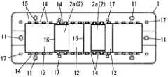
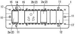
以下では、図1および図2のように、壁などの施工面(図示せず)側を後面として施工面に取り付けられる配線器具用プレート1に、配線器具2を取り付けた配線装置を示す。  Hereinafter, as shown in FIGS. 1 and 2, a wiring device is shown in which awiring device 2 is attached to awiring device plate 1 that is attached to a construction surface with a construction surface (not shown) side such as a wall as a rear surface.

本実施形態で例示する配線器具用プレート1は、前面が矩形状に形成され、配線器具2が前方より挿入されて取り付けられる取付孔12が前後方向(厚み方向)に貫設される。  Thewiring device plate 1 exemplified in the present embodiment has a rectangular front surface, and amounting hole 12 into which thewiring device 2 is inserted and attached from the front is provided in the front-rear direction (thickness direction).

配線器具用プレート1の後面には、取付孔12を囲む形で挿入リブ18が突設され、取付孔12の周部には、施工面への固定用の取付ねじが挿通されるねじ用挿通孔11が複数個、前後方向に貫設される。施工面に設けられた施工孔(図示せず)に挿入リブ18を挿入した後、取付ねじで配線器具用プレート1は施工面に固定される。  Insertion ribs 18 project from the rear surface of thewiring instrument plate 1 so as to surround theattachment holes 12, and screw attachments through which attachment screws for fixing to the construction surface are inserted are inserted into the periphery of theattachment holes 12. A plurality ofholes 11 are provided in the front-rear direction. After inserting theinsertion rib 18 into a construction hole (not shown) provided on the construction surface, thewiring device plate 1 is fixed to the construction surface with a mounting screw.

すなわち、取付孔12は、施工孔の前方に位置し、配線器具2は、後部が施工面に埋め込まれる形で取付孔12に取り付けられる。  That is, theattachment hole 12 is located in front of the construction hole, and thewiring device 2 is attached to theattachment hole 12 such that the rear part is embedded in the construction surface.

配線器具2が取り付けられた配線器具用プレート1の前面には、配線器具用プレート1の前面の形状と略同形状の化粧プレートPが取り付けられる。化粧プレートPは、配線器具2を前面側に露出される窓42を備える。化粧プレートPの配線器具用プレート1への取り付けは、配線器具用プレート1の前面に形成した複数個の係合孔17と、化粧プレートPの後面に形成した複数個の係合爪41とをそれぞれ係合させることにより行う。  A decorative plate P having substantially the same shape as the front surface of thewiring device plate 1 is attached to the front surface of thewiring device plate 1 to which thewiring device 2 is attached. The decorative plate P includes awindow 42 through which thewiring device 2 is exposed to the front side. The decorative plate P is attached to thewiring device plate 1 with a plurality ofengaging holes 17 formed on the front surface of thewiring device plate 1 and a plurality ofengaging claws 41 formed on the rear surface of the decorative plate P. It is performed by engaging each.

配線器具用プレート1の長手方向に沿って複数個(図示例では、8個)の配線器具2を密に並べて取付孔12に取り付けることができる配線器具2の大きさを、単位寸法として、配線器具2は、単位寸法を基にその形状が決められる。たとえば、配線器具2は単位寸法や、単位寸法の2、3、1.5倍などの大きさで形成される。  The size of thewiring device 2 that can be mounted in themounting hole 12 by arranging a plurality (eight in the illustrated example) ofwiring devices 2 along the longitudinal direction of thewiring device plate 1 is set as a unit dimension. The shape of theinstrument 2 is determined based on the unit dimensions. For example, thewiring device 2 is formed in a unit dimension or a size such as 2, 3, 1.5 times the unit dimension.

配線器具2は、たとえば、スイッチやコンセントなどである。但し、電話線やテレビ用のアンテナ線などが接続される器具であってもよい。本実施形態では、配線器具2として、単位寸法で形成されるスイッチ2aと、単位寸法の2倍の大きさで形成されるコンセント2bとを例示する。すなわち、スイッチ2aは、取付孔12に8個取り付けることができ、コンセント2bは、取付孔12に4個取り付けることができる。  Thewiring device 2 is, for example, a switch or an outlet. However, it may be a device to which a telephone line or a television antenna line is connected. In the present embodiment, as thewiring device 2, aswitch 2a formed with unit dimensions and anoutlet 2b formed with twice the unit dimensions are illustrated. That is, eightswitches 2a can be attached to theattachment holes 12, and fouroutlets 2b can be attached to theattachment holes 12.

配線器具2は、前面が矩形状に形成され電源線(図示せず)が接続される端子部を内部に有する器体21を備える。スイッチ2aにおいては、器体21の前面にはスイッチ操作部30が設けられる。コンセント2bにおいては、プラグの栓刃(図示せず)が差し込まれるプラグ挿入孔31が器体21の前面に開設される。  Thewiring device 2 includes acontainer body 21 having a terminal portion to which a front surface is formed in a rectangular shape and a power line (not shown) is connected. In theswitch 2 a, aswitch operation unit 30 is provided on the front surface of thecontainer body 21. In theoutlet 2b, aplug insertion hole 31 into which a plug blade (not shown) of the plug is inserted is opened on the front surface of thecontainer body 21.

器体21の後面には、電源線が挿入される端子孔22が開設される。また、器体21の前端部の周面には、フランジ23が突設される。以下では、配線器具用プレート1の長手方向を横方向、短手方向を縦方向として説明を行う。  Aterminal hole 22 into which a power supply line is inserted is opened on the rear surface of thecontainer body 21. Further, aflange 23 projects from the peripheral surface of the front end portion of thecontainer body 21. Below, the longitudinal direction of theplate 1 for wiring devices is demonstrated as a horizontal direction, and a transversal direction is demonstrated as a vertical direction.

図3に示すように、縦方向におけるフランジ23の両端部の後面には、取付脚26が形成される。スイッチ2aにおいては、フランジ23の各端部の中央に各1個(合計2個)形成され、コンセント2bにおいては、フランジ23の各端部に各2個(合計4個)形成される。  As shown in FIG. 3, mountinglegs 26 are formed on the rear surfaces of both end portions of theflange 23 in the vertical direction. In theswitch 2a, one piece (two in total) is formed at the center of each end of theflange 23, and two pieces (four in total) are formed in each end of theflange 23 in theoutlet 2b.

単位寸法で形成されるスイッチ2aを2個近接して縦方向に並べた場合の4つの取付脚26の位置と同じ位置になるように、コンセント2bに形成される4つの取付脚26の形成位置が決められる。  Positions of the four mountinglegs 26 formed on theoutlet 2b so that they are in the same position as the positions of the four mountinglegs 26 when twoswitches 2a formed with unit dimensions are arranged close to each other in the vertical direction. Is decided.

各取付脚26は、器体21の4つの周面のうち縦方向に互いに並行する一組の周面25にそれぞれ沿うとともに、周面25との間に隙間を有するようにそれぞれ形成される。さらに、取付脚26は、周面25との間の距離を可変とする弾性を有する。すなわち、取付脚26は、周面25に近づくように撓むことができる。  Each mountingleg 26 is formed so as to be along a set ofperipheral surfaces 25 parallel to each other in the vertical direction among the four peripheral surfaces of thecontainer body 21 and to have a gap between the peripheral surfaces 25. Furthermore, theattachment leg 26 has elasticity that makes the distance between theperipheral surface 25 variable. That is, the mountingleg 26 can be bent so as to approach theperipheral surface 25.

各取付脚26の先端部には、縦方向において互いに離れる向きに引掛爪27がそれぞれ突設される。  A hookingclaw 27 projects from the tip of each mountingleg 26 in a direction away from each other in the vertical direction.

また、フランジ23における縦方向に互いに対向する両端面には、鉤片28がそれぞれ突設される。鉤片28は、フランジ23の端面から突出する鉤片基部28aと、鉤片基部28aの先端部から後方に突出する鉤片凸部28bとを備える。鉤片28は、各取付脚26の両側に形成される。すなわち、スイッチ2aにおいては、各端面に2個ずつ、計4個の鉤片28が形成され、コンセント2bにおいては、各端面に4個ずつ、計8個の鉤片28が形成される。  Further,flanges 28 are respectively provided on both end surfaces of theflange 23 facing each other in the vertical direction. Theflange piece 28 includes a flangepiece base portion 28a that protrudes from the end face of theflange 23, and a flangepiece protrusion portion 28b that protrudes backward from the tip end portion of the flangepiece base portion 28a. Thecollar piece 28 is formed on both sides of each mountingleg 26. That is, in theswitch 2a, a total of fourhooks 28 are formed, two on each end face, and in theoutlet 2b, a total of eighthooks 28 are formed on each end face.

なお、図4(a)に示すように、スイッチ2a’において、取付脚26を各側に2個ずつ形成し(すなわち、取付脚26を4個形成)、横方向に並ぶ2つの取付脚26の中間に鉤片28を形成する構成とすることもできる。  As shown in FIG. 4A, in theswitch 2a ′, two mountinglegs 26 are formed on each side (that is, four mountinglegs 26 are formed), and two mountinglegs 26 aligned in the lateral direction are formed. It can also be set as the structure which forms thecollar piece 28 in the middle.

また、図4(b)に示すように、コンセント2b’において、鉤片28を取付脚26の片側(図示例では、2個の取付脚26間に位置することになる側)のみに形成する構成とすることもできる。  Further, as shown in FIG. 4B, in theoutlet 2b ′, thehook piece 28 is formed only on one side of the mounting leg 26 (in the illustrated example, the side that is to be positioned between the two mounting legs 26). It can also be configured.

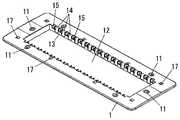
一方、配線器具用プレート1においては、図1および図2に示すように、取付孔12の4つの内周面のうち、縦方向に互いに対向する一組の内周面13には、前後方向に沿う取付溝14が複数本づつ凹設される。  On the other hand, in thewiring device plate 1, as shown in FIGS. 1 and 2, among the four inner peripheral surfaces of the mountinghole 12, the set of innerperipheral surfaces 13 facing each other in the vertical direction has a front-rear direction. A plurality of mountinggrooves 14 are recessed along the line.

取付溝14は、配線器具用プレート1の前面に開口を有し、取付溝14は前面に露出する。取付溝14の幅寸法(横方向の長さ寸法)は、取付溝14が取付脚26と嵌合可能なように、取付脚26の幅寸法(横方向の長さ寸法)と略同一寸法で形成される。  The mountinggroove 14 has an opening on the front surface of thewiring device plate 1, and the mountinggroove 14 is exposed on the front surface. The width dimension (lateral length dimension) of the mountinggroove 14 is substantially the same as the width dimension (lateral length dimension) of the mountingleg 26 so that the mountinggroove 14 can be fitted to the mountingleg 26. It is formed.

取付溝14の前面の開口の両側には、各鉤片28がそれぞれ差し込まれる複数個の差込孔15が開設される。配線器具用プレート1における差込孔15と取付孔12との間の部位の前面は、差込孔15の開口より後方に位置し、支持台19を形成する。
図5および図6に示すように、各取付脚26が各取付溝14内にそれぞれ進入するように、配線器具2を前方より取付孔12内に挿入すると、引掛爪27が取付溝14の底面14cに接触して撓み、また、各鉤片凸部28bが各差込孔15にそれぞれ差し込まれて、鉤片基部28aの後面が支持台19の前面に当接する。ここに、取付脚26と周面25との間の距離は、引掛爪27の突出寸法よりも大きく形成され、取付脚26は、周面25に当ることはない。
A plurality of insertion holes 15 into which theflanges 28 are respectively inserted are opened on both sides of the front opening of the mountinggroove 14. The front surface of the portion between theinsertion hole 15 and theattachment hole 12 in thewiring instrument plate 1 is located behind the opening of theinsertion hole 15 and forms asupport base 19.
As shown in FIG. 5 and FIG. 6, when thewiring device 2 is inserted into the mountinghole 12 from the front so that each mountingleg 26 enters the mountinggroove 14, the hookingclaw 27 is placed on the bottom surface of the mountinggroove 14. 14 c contacts and bends, and theflange protrusions 28 b are inserted into the insertion holes 15, respectively, and the rear surface of theflange base 28 a comes into contact with the front surface of thesupport 19. Here, the distance between the mountingleg 26 and theperipheral surface 25 is formed to be larger than the protruding dimension of the catchingclaw 27, and the mountingleg 26 does not hit theperipheral surface 25.

また、鉤片基部28aの後面が支持台19の前面に当接したときに引掛爪27が配線器具用プレート1の後面(取付孔12に沿う部位の後面)に引っ掛かるような前後方向の長さ寸法で、取付孔12は形成される。すなわち、鉤片基部28aの後面が支持台19の前面に当接すると、引掛爪27の前面は配線器具用プレート1の後面に係止される。本実施形態では、上述のように、配線器具用プレート1の後面(取付孔12に沿う部位の後面)を、引掛爪27を受ける爪受部としている。  Further, the length in the front-rear direction is such that the hookingclaw 27 is caught on the rear surface of the wiring device plate 1 (the rear surface along the mounting hole 12) when the rear surface of theflange base 28a comes into contact with the front surface of thesupport base 19. With dimensions, the mountinghole 12 is formed. That is, when the rear surface of thehook base 28 a comes into contact with the front surface of thesupport base 19, the front surface of the hookingclaw 27 is locked to the rear surface of thewiring device plate 1. In the present embodiment, as described above, the rear surface of the wiring device plate 1 (the rear surface of the portion along the attachment hole 12) is a claw receiving portion that receives the hookingclaw 27.

上述より、配線器具2は、取付脚26が取付溝14に嵌まることで縦方向および横方向の移動が規制され、鉤片基部28aの後面が支持台19の前面に当接し、かつ、引掛爪27の前面が配線器具用プレート1の後面に係止されることで、前後方向の移動が規制される。すなわち、配線器具2は、配線器具用プレート1に固定される。  As described above, thewiring device 2 is restricted from moving in the vertical direction and the horizontal direction by fitting the mountinglegs 26 into the mountinggrooves 14, the rear surface of thehook base 28 a abuts against the front surface of thesupport base 19, and the hook. Since the front surface of theclaw 27 is locked to the rear surface of thewiring device plate 1, movement in the front-rear direction is restricted. That is, thewiring device 2 is fixed to thewiring device plate 1.

なお、図7に示すように、差込孔15における横方向に互いに対向する一組の壁面に、前後方向に沿う一対のリブ15cを形成することができる。リブ15cは、その突出方向(横方向)に潰れることができる程度の厚み寸法(縦方向の幅寸法)で形成される。また、後方ほど突出寸法が大きくなるように、リブ15は形成される。  In addition, as shown in FIG. 7, a pair of rib 15c along a front-back direction can be formed in a pair of wall surface which mutually opposes in theinsertion hole 15 in the horizontal direction. The rib 15c is formed with a thickness dimension (width dimension in the vertical direction) that can be crushed in the protruding direction (lateral direction). Further, theribs 15 are formed so that the protruding dimension increases toward the rear.

一方、鉤片28の幅寸法(横方向の長さ寸法)は、差込孔15の幅寸法よりも小さく、かつ、一対のリブ15cの後部における先端間の寸法よりも大きく形成され、鉤片凸部28dは、差込孔15内に進入する際にリブ15cを押し潰す。したがって、鉤片28と差込孔15との間の横方向における隙間が、押し潰されたリブ15cにより埋められ、配線器具2の横方向のがたつきが防止される。  On the other hand, the width dimension (lateral length dimension) of theflange piece 28 is smaller than the width dimension of theinsertion hole 15 and larger than the dimension between the tips of the rear portions of the pair of ribs 15c. The convex portion 28 d crushes the rib 15 c when entering theinsertion hole 15. Therefore, the gap in the lateral direction between theflange piece 28 and theinsertion hole 15 is filled with the crushed rib 15c, and the rattling of thewiring device 2 in the lateral direction is prevented.

次に、配線器具2の取り外しについて、図8を参照して説明する。上述したように、取付溝14は前面側に開口を有し、前面側に露出している。マイナスドライバーなどの工具Aの先端を取付溝14に前方より差し込んで図中の矢印のように動かして取付脚26を器体21の周面25側に撓ませると、引掛爪27は配線器具用プレート1の後面から外れ、引掛爪27の後面と配線器具用プレート1の後面との係止が解除される。すなわち、配線器具2は、配線器具用プレート1から取り外される。  Next, removal of thewiring device 2 will be described with reference to FIG. As described above, the mountinggroove 14 has an opening on the front side and is exposed on the front side. When the tip of a tool A such as a flat-blade screwdriver is inserted into the mountinggroove 14 from the front and moved as indicated by the arrow in the figure, the mountingleg 26 is bent toward theperipheral surface 25 side of thebody 21, and the hookingclaw 27 is used for wiring equipment. It comes off from the rear surface of theplate 1 and the engagement between the rear surface of the hookingclaw 27 and the rear surface of thewiring device plate 1 is released. That is, thewiring device 2 is removed from thewiring device plate 1.

ここに、図5に示すように、2つの内周面13にそれぞれ形成されて縦方向に互いに向かい合う2つの取付溝14の各底面14cは、前方に向かうに従って互いに離れる向きに傾斜する傾斜面に形成される。したがって、底面14cの傾斜角度に応じて、取付溝14の開口における底面14cと取付脚26との間の隙間寸法dが決まる。  Here, as shown in FIG. 5, the bottom surfaces 14 c of the two mountinggrooves 14 formed on the two innerperipheral surfaces 13 and facing each other in the vertical direction are inclined surfaces that are inclined away from each other toward the front. It is formed. Therefore, the gap dimension d between thebottom surface 14c and the mountingleg 26 at the opening of the mountinggroove 14 is determined according to the inclination angle of thebottom surface 14c.

本実施形態では、隙間寸法dは、配線器具用プレート1の枠部の幅寸法(縦方向における取付孔12の縁と配線器具用プレート1の外縁との間の長さ寸法)まで大きくできるから、当該枠部の幅寸法を大きくすることで取付脚26に工具Aを差し込むための切欠溝を形成した従来構成よりも隙間寸法dを大きくすることができ、結果、図8に示すように、工具Aの先端を取付溝14の開口に差し込み易くなっている。また、工具Aの先端が底面14cを摺動することにより取付脚26側に案内されるから、取付溝14の開口を大きくても、配線器具2を取り外す作業に支障を及ぼすことがなく、配線器具2の取り外し作業が容易である。  In the present embodiment, the gap dimension d can be increased up to the width dimension of the frame portion of the wiring instrument plate 1 (the length dimension between the edge of the mountinghole 12 and the outer edge of thewiring instrument plate 1 in the vertical direction). By increasing the width dimension of the frame portion, the gap dimension d can be made larger than the conventional configuration in which the notch groove for inserting the tool A into the mountingleg 26 is formed. As a result, as shown in FIG. It is easy to insert the tip of the tool A into the opening of the mountinggroove 14. In addition, since the tip of the tool A is guided to the mountingleg 26 side by sliding on thebottom surface 14c, even if the opening of the mountinggroove 14 is large, the work for removing thewiring device 2 is not hindered. The removal work of theinstrument 2 is easy.

なお、前記従来構成では、切欠溝の深さ寸法を大きくするとその分取付脚の厚み寸法が小さくなり工具Aによって取付脚が損壊する虞があるが、本実施形態では、取付溝14は配線器具用プレート1に形成されるから、隙間寸法dを大きくしても取付脚26の強度が低下することはない。また、取付溝14の周囲における配線器具用プレート1の肉厚を大きくすることで取付溝14の強度も十分に確保することができる。結果、前記従来構成よりも、工具Aによる損壊の可能性を低下させることができる。  In the above-described conventional configuration, when the depth dimension of the notch groove is increased, the thickness dimension of the mounting leg is reduced accordingly, and the mounting leg may be damaged by the tool A. However, in this embodiment, the mountinggroove 14 is a wiring device. Since it is formed on theplate 1, the strength of the mountingleg 26 does not decrease even if the gap dimension d is increased. Moreover, the strength of the mountinggroove 14 can be sufficiently ensured by increasing the thickness of thewiring device plate 1 around the mountinggroove 14. As a result, the possibility of damage by the tool A can be reduced as compared with the conventional configuration.

また、前記従来構成では、切欠溝を取付脚に形成するから、切欠溝の幅寸法は取付脚の幅寸法より小さくなるが、本実施形態では、取付溝14の幅寸法(横方向の長さ寸法)は、取付脚26の幅寸法と略同一寸法である。すなわち、取付溝14の幅寸法は、前記従来構成よりも大きくなり、工具Aの先端を取付溝14に差し込み易くなる。  In the conventional configuration, since the notch groove is formed in the mounting leg, the width dimension of the notch groove is smaller than the width dimension of the mounting leg. However, in this embodiment, the width dimension of the mounting groove 14 (the length in the lateral direction). The dimension) is substantially the same as the width dimension of the mountingleg 26. That is, the width dimension of the mountinggroove 14 is larger than that of the conventional configuration, and the tip of the tool A can be easily inserted into the mountinggroove 14.

ところで、図9に示すように、取付孔12の内周面13において横方向に並んで形成される各取付溝14は、スイッチ2aの横方向の長さ寸法の寸法間隔で形成される取付溝14aと、隣接する2つの取付溝14aの中間に形成される取付溝14bとで構成される。  By the way, as shown in FIG. 9, the mountinggrooves 14 formed side by side in the innerperipheral surface 13 of the mountinghole 12 are mounting grooves formed at intervals of the lateral length of theswitch 2 a. 14a and a mountinggroove 14b formed between two adjacent mountinggrooves 14a.

また、隣接する2個の取付溝14aの中間には、2つの内周面13間を連結する複数本(図示例では3本)の変形防止用桟16が設けられる。各変形防止用桟16は、スイッチ2aの横方向の長さ寸法の2倍の寸法間隔で形成される。  In addition, a plurality of (three in the illustrated example)deformation preventing bars 16 that connect the two innerperipheral surfaces 13 are provided in the middle between two adjacent mountinggrooves 14a. Thedeformation preventing bars 16 are formed at a dimensional interval twice as long as the lateral length of theswitch 2a.

なお、図における3本の変形防止用桟16のうち、中央の変形防止用桟16のように、隣接する2個の取付溝14aの間に形成された取付溝14bに変形防止用桟16を接続することもできるし、図における3本の変形防止用桟16のうち、両端の変形防止用桟16のように、隣接する2つの取付溝14aの間であって取付溝14bを形成していない部位に、変形防止用桟16を形成することもできる。  Of the three deformation prevention bars 16 in the figure, the deformation prevention bars 16 are formed in the mountinggrooves 14b formed between two adjacent mountinggrooves 14a, like the central deformation prevention bars 16. Of the three deformation prevention bars 16 in the figure, like the deformation prevention bars 16 at both ends, a mountinggroove 14b is formed between two adjacent mountinggrooves 14a. It is also possible to form thedeformation prevention bar 16 in a portion that is not present.

上述より、各内周面13に設けられる各取付溝14は、3個ごとに変形防止用桟16により区切られた形になっている。変形防止用桟16に区切られた取付孔12の各部位において、3個の取付溝14のうち端に位置する取付溝14に取付脚26が嵌るようにスイッチ2aを取り付けると、前述したように、変形防止用桟16は隣接する2個の取付溝14aの中間に形成され、隣接する2個の取付溝14a間の距離はスイッチ2aの横方向の長さ寸法と略同一寸法であり、取付脚26は器体前端部22の横方向における中央に形成されているから、スイッチ2a(図における左側のスイッチ2a)は、変形防止用桟16に寄り添う。  As described above, each mountinggroove 14 provided on each innerperipheral surface 13 is divided into three by the deformation preventing bars 16. When theswitch 2a is attached so that theattachment leg 26 fits into theattachment groove 14 located at the end of the threeattachment grooves 14 in each part of theattachment hole 12 partitioned by thedeformation prevention bar 16, as described above. Thedeformation prevention bar 16 is formed in the middle of the two adjacent mountinggrooves 14a, and the distance between the two adjacent mountinggrooves 14a is substantially the same as the horizontal dimension of theswitch 2a. Since theleg 26 is formed at the center in the lateral direction of thefront end portion 22 of the body, theswitch 2a (theswitch 2a on the left side in the figure) approaches thedeformation preventing bar 16.

また、変形防止用桟16に区切られた取付孔12の各部位において、3個の取付溝14のうち真ん中に位置する取付溝14に取付脚26が嵌るようにスイッチ2aを取り付けると、スイッチ2a(図における右側のスイッチ2a)は、2つの変形防止用桟16の真ん中に位置する。  Further, when theswitch 2a is attached so that theattachment leg 26 fits into theattachment groove 14 located in the middle of the threeattachment grooves 14 in each part of theattachment hole 12 partitioned by thedeformation preventing bar 16, theswitch 2a (Theswitch 2a on the right side in the figure) is located in the middle of the two deformation preventing bars 16.

上述のように、変形防止用桟16に区切られた取付孔12の各部位において、横方向におけるスイッチ2aの長さ寸法の半分の長さごとに横方向にずらしてスイッチ2aを取付孔12に取り付けることができる。  As described above, in each part of the mountinghole 12 partitioned by thedeformation prevention bar 16, theswitch 2a is shifted to the mountinghole 12 by shifting in the horizontal direction every half of the length of theswitch 2a in the horizontal direction. Can be attached.

なお、図11に示すように、変形防止用桟16(図9参照)を設けない構成とすることもできる。その場合、取付溝14は、横方向におけるスイッチ2aの長さ寸法の半分の寸法間隔で形成される。すなわち、配線器具2は、図12に示すように、横方向におけるスイッチ2aの長さ寸法の半分の寸法間隔で横方向にずらして取付孔12に取り付けることができる。  In addition, as shown in FIG. 11, it can also be set as the structure which does not provide the deformation | transformation prevention crosspiece 16 (refer FIG. 9). In that case, the mountinggroove 14 is formed at a dimensional interval that is half the length of theswitch 2a in the lateral direction. That is, as shown in FIG. 12, thewiring device 2 can be attached to theattachment hole 12 while being shifted in the horizontal direction at a distance that is half the length of theswitch 2 a in the horizontal direction.

ところで、変形防止用桟16は、取付孔12の2つの内周面13を連結するから、変形防止用桟16により、2つの内周面13間の距離が広がるように配線器具用プレート1が変形することが防止される。  By the way, thedeformation preventing bar 16 connects the two innerperipheral surfaces 13 of the mountinghole 12, so thedeformation preventing bar 16 allows thewiring device plate 1 to be extended so that the distance between the two innerperipheral surfaces 13 is increased. Deformation is prevented.

したがって、配線器具用プレート1が変形して、引掛爪27が爪受部である配線器具用プレート1の後面(取付孔12に沿う端部における後面)から外れるということがない。  Therefore, thewiring device plate 1 is not deformed, and the hookingclaw 27 does not come off the rear surface of thewiring device plate 1 that is the claw receiving portion (the rear surface at the end portion along the attachment hole 12).

変形防止用桟16は、図13に示すように、器体21の前端部であるフランジ23の後方となる位置に、かつ、器体21の後端部である幅狭部の側方に位置するように形成される。したがって、配線器具2を、変形防止用桟16に寄り添うように、変形防止用桟16の両側に取り付けると、2つの配線器具2のそれぞれのフランジ23により変形防止用桟16が隠される。結果、変形防止用桟16により美観が損なわれることがない。  As shown in FIG. 13, thedeformation preventing bar 16 is located at a position behind theflange 23 that is the front end portion of thecontainer body 21 and at a side of the narrow portion that is the rear end portion of thecontainer body 21. To be formed. Therefore, when thewiring device 2 is attached to both sides of thedeformation preventing beam 16 so as to be close to thedeformation preventing beam 16, thedeformation preventing beam 16 is hidden by therespective flanges 23 of the twowiring devices 2. As a result, the aesthetic appearance is not impaired by thedeformation preventing bar 16.

ところで、本実施形態では、器体21の2つの周面25は、図3に示すように、後方(図における下向き)ほど互いに近づくように傾斜させて形成される。したがって、縦方向における器体21の後面の長さ寸法は、取付孔12の縦方向の長さ寸法よりも小さくなり、配線器具2を取付孔12に前方より挿入する際に、器体21,21bを取付孔12に挿入し易く、また、周面25と取付孔12の内周面13とが摺接することにより、配線器具2が定位置(取付位置)に案内されるから、配線器具2を取付孔12に取り付ける作業が容易になる。  By the way, in this embodiment, as shown in FIG. 3, the twoperipheral surfaces 25 of thecontainer body 21 are formed to be inclined so as to approach each other toward the rear (downward in the drawing). Accordingly, the length dimension of the rear surface of thecontainer body 21 in the vertical direction is smaller than the length dimension of the mountinghole 12 in the vertical direction, and when thewiring device 2 is inserted into the mountinghole 12 from the front, 21 b can be easily inserted into the mountinghole 12, and thewiring device 2 is guided to a fixed position (mounting position) by the sliding contact between theperipheral surface 25 and the innerperipheral surface 13 of the mountinghole 12. The operation of attaching the to theattachment hole 12 becomes easy.

なお、配線器具用プレート1は、縦方向を上下方向として施工面に取り付けることもできるし、横方向を上下方向として施工面に取り付けることをできる。  In addition, theplate 1 for wiring devices can also be attached to a construction surface by making a vertical direction into an up-down direction, and can be attached to a construction surface by making a horizontal direction into an up-down direction.

実施形態の前面側から見た分解斜視図である。It is the disassembled perspective view seen from the front side of embodiment.実施形態の後面側から見た分解斜視図である。It is the disassembled perspective view seen from the rear surface side of embodiment.実施形態の配線器具の平面図である。It is a top view of the wiring device of an embodiment.実施形態の配線器具の別形態の斜視図である。It is a perspective view of another form of the wiring device of an embodiment.実施形態の取付脚部分における垂直断面図である。It is a vertical sectional view in the mounting leg portion of the embodiment.実施形態の鉤片部分における垂直断面図である。It is a vertical sectional view of the flange portion of the embodiment.実施形態の配線器具用プレートにおける差込孔部分の拡大図である。It is an enlarged view of the insertion hole part in the plate for wiring devices of embodiment.実施形態の配線器具を配線器具用プレートから取り外す状態の図である。It is a figure of the state which removes the wiring device of embodiment from the plate for wiring devices.実施形態の配線器具用プレートの斜視図である。It is a perspective view of the plate for wiring devices of embodiment.実施形態の配線器具用プレートに配線器具を取り付けた平面図である。It is the top view which attached the wiring device to the plate for wiring devices of embodiment.実施形態の配線器具用プレートの別形態の斜視図である。It is a perspective view of another form of the plate for wiring devices of embodiment.実施形態の別形態の配線器具用プレートに配線器具を取り付けた平面図である。It is the top view which attached the wiring apparatus to the plate for wiring apparatuses of another form of embodiment.実施形態の取付孔の長手方向に沿う垂直断面図である。It is a vertical sectional view along the longitudinal direction of the mounting hole of the embodiment.従来例を示す分解斜視図である。It is a disassembled perspective view which shows a prior art example.

符号の説明Explanation of symbols

1 配線器具用プレート
2 配線器具
2a スイッチ
2b コンセント
12 取付孔
13 内周面
14,14a,14b 取付溝
14c 底面
15 差込孔
16 変形防止用桟
19 支持台
21 器体
25 周面
26 取付脚
27 引掛爪
28 鉤片
DESCRIPTION OFSYMBOLS 1Wiring device plate 2Wiringdevice 2aSwitch 2b Outlet 12Mounting hole 13 Innerperipheral surface 14, 14a,14b Mounting groove14c Bottom surface 15Insertion hole 16Deformation prevention crosspiece 19Support base 21Body 25Peripheral surface 26 Mountingleg 27Hook nail 28

Claims (4)

Translated fromJapanese
施工面側を後面として施工面に固定され前面が矩形状に開口した取付孔を有する配線器具用プレートと、前面が矩形状である器体を有し取付孔に挿入された形で取り付けられた配線器具とを備える配線装置であって、配線器具は、器体の周面のうち互いに並行する一組の周面に沿って後方にそれぞれ突設され当該周面との距離を可変とする向きの弾性をそれぞれ有する取付脚を備え、各取付脚の先端部には、互いに離れる向きに引掛爪がそれぞれ突設され、配線器具用プレートは、取付孔の4面の内周面のうち互いに対向する一組の内周面において前後方向に沿って凹設され各取付脚とそれぞれ嵌合する取付溝と、各取付溝の後方にそれぞれ設けられて各引掛爪の前面をそれぞれ係止する爪受部と、取付溝が形成された取付孔の各内周面に設けられ配線器具を後方より支持する支持台とを備え、各取付溝の底面は、前方に向かうに従って互いに離れる向きに傾斜する傾斜面であり、取付脚と前記底面との間に配線器具用プレートの前面に露出する隙間が形成されていることを特徴とする配線装置。  It was fixed to the construction surface with the construction surface side as the rear surface, and the wiring equipment plate having a mounting hole whose front surface was opened in a rectangular shape, and the front surface was mounted in a shape inserted into the mounting hole with a rectangular body A wiring device comprising a wiring device, wherein the wiring device protrudes rearward along a set of peripheral surfaces parallel to each other of the peripheral surfaces of the vessel body, and the distance between the peripheral surfaces is variable. Each of the mounting legs has hooking claws projecting in directions away from each other, and the wiring device plates are opposed to each other among the four inner peripheral surfaces of the mounting holes. A pair of inner circumferential surfaces that are recessed along the front-rear direction and fitted with each mounting leg, and a claw receiver that is provided behind each mounting groove and that locks the front surface of each hooking claw. And each inner peripheral surface of the mounting hole where the mounting groove is formed A support base that supports the wiring device from the rear, and the bottom surface of each mounting groove is an inclined surface that is inclined away from each other toward the front, and the wiring device plate is disposed between the mounting leg and the bottom surface. A wiring device having a gap exposed on the front surface. 前記配線器具用プレートには、前記各爪受部にそれぞれ隣接する部位において前面に開口する差込孔が形成され、前記配線器具は、各差込孔にそれぞれ差し込まれる複数個の鉤片を備えることを特徴とする請求項1に記載の配線装置。  The wiring device plate is formed with insertion holes that open to the front surface at portions adjacent to the respective claw receiving portions, and the wiring device includes a plurality of flanges that are respectively inserted into the insertion holes. The wiring device according to claim 1. 前記取付孔は、前記取付溝が並ぶ内周面の延長方向において単位寸法の複数個の配線器具を取付可能な大きさに形成され、前記配線器具は、前記延長方向における寸法が前端部より小さい幅狭部を後端部に有し、取付孔の内周面のうち取付溝が形成された2つの内周面間は変形防止用桟により連結され、変形防止用桟は、変形防止用桟を挟んで隣接して隙間なく取り付けられる2つの配線器具の中間であって前記配線器具の幅狭部間に形成されることを特徴とする請求項1または請求項2に記載の配線装置。  The mounting hole is formed to have a size capable of mounting a plurality of wiring devices having unit dimensions in the extending direction of the inner peripheral surface in which the mounting grooves are arranged, and the wiring device has a size in the extending direction smaller than the front end portion. The inner peripheral surface of the mounting hole having a narrow portion at the rear end portion is connected between the two inner peripheral surfaces formed with the mounting grooves by a deformation preventing bar, and the deformation preventing bar is a deformation preventing bar. 3. The wiring device according to claim 1, wherein the wiring device is formed between a narrow portion of the wiring device that is intermediate between two wiring devices that are attached adjacent to each other with no gap therebetween. 前記取付脚が沿う前記器体の一組の周面は、後方ほど互いに近づくように傾斜していることを特徴とする請求項1乃至請求項3の何れか1項に記載の配線装置。


4. The wiring device according to claim 1, wherein a pair of peripheral surfaces of the container along which the mounting legs are aligned are inclined so as to approach each other toward the rear. 5.


JP2008217378A2008-08-262008-08-26 Wiring deviceExpired - Fee RelatedJP4936197B2 (en)

Priority Applications (2)

Application NumberPriority DateFiling DateTitle
JP2008217378AJP4936197B2 (en)2008-08-262008-08-26 Wiring device
CN2009101704576ACN101662092B (en)2008-08-262009-08-26Wiring device

Applications Claiming Priority (1)

Application NumberPriority DateFiling DateTitle
JP2008217378AJP4936197B2 (en)2008-08-262008-08-26 Wiring device

Publications (2)

Publication NumberPublication Date
JP2010057227A JP2010057227A (en)2010-03-11
JP4936197B2true JP4936197B2 (en)2012-05-23

Family

ID=41789957

Family Applications (1)

Application NumberTitlePriority DateFiling Date
JP2008217378AExpired - Fee RelatedJP4936197B2 (en)2008-08-262008-08-26 Wiring device

Country Status (2)

CountryLink
JP (1)JP4936197B2 (en)
CN (1)CN101662092B (en)

Families Citing this family (8)

* Cited by examiner, † Cited by third party
Publication numberPriority datePublication dateAssigneeTitle
WO2011146429A1 (en)*2010-05-172011-11-24Thales Avionics, Inc.Airline passenger seat modular user interface device
JP5608028B2 (en)*2010-09-272014-10-15パナソニック株式会社 Mounting frame and wiring device
JP5557706B2 (en)*2010-11-152014-07-23株式会社日立産機システム Protective cover for electrical equipment
CN105280412B (en)*2014-07-142019-06-04进联电子科技(上海)有限公司Switching device improved structure
ZA201509303B (en)*2014-12-222022-12-21Schneider Electric Australia Pty LtdSwitch assembly, system and method
JP6459674B2 (en)*2015-03-182019-01-30三菱電機株式会社 Wall installation device
JP6390981B2 (en)*2016-09-152018-09-19パナソニックIpマネジメント株式会社 Wiring device, mounting frame, and wiring device system
CN108122697B (en)*2016-11-282021-01-29松下知识产权经营株式会社Plate for wiring device and wiring device assembly

Family Cites Families (6)

* Cited by examiner, † Cited by third party
Publication numberPriority datePublication dateAssigneeTitle
JPH0297819A (en)*1988-09-301990-04-10Matsushita Refrig Co Ltd perishable storage equipment
JPH02228208A (en)*1989-02-281990-09-11Toshiba Lighting & Technol CorpMounting frame
JP3901819B2 (en)*1997-11-282007-04-04神保電器株式会社 Wiring equipment for equipment
JP3503503B2 (en)*1998-11-252004-03-08松下電工株式会社 Wiring plate
JP2001216871A (en)*2000-02-042001-08-10Matsushita Electric Works LtdPiano handle-type switch
JP2005347074A (en)*2004-06-022005-12-15Daiwa Kasei Ind Co LtdSwitch mounting structure of vehicle

Also Published As

Publication numberPublication date
CN101662092A (en)2010-03-03
CN101662092B (en)2012-05-23
JP2010057227A (en)2010-03-11

Similar Documents

PublicationPublication DateTitle
JP4936197B2 (en) Wiring device
JP4126179B2 (en) connector
US20060166549A1 (en)Wire cover for connectors
JP2006253017A (en)Joint connector
KR101275569B1 (en)An accepting box mounting structure for refrigerator
JP5649638B2 (en) Control device
JP2008082018A (en)Vehicular door handle
JP2013013203A (en)Cabinet for housing electric apparatus
JP4749147B2 (en) Breaker mounting structure
US10044178B2 (en)Notification appliance enclosure
JP2009167777A (en)Form panel, connecting fixture and removing fixture
JP3740997B2 (en) Wiring plate
JP2012054092A (en)Connector and retainer
KR101287223B1 (en)A fixing device for multi terminal main PCB
JP2009153667A (en) Mounting structure of slide rail device
JP4919835B2 (en) Door lock bracket
JP5385750B2 (en) Terminal equipment
JP5080800B2 (en) Distribution board
JP5086825B2 (en) Mounting frame and wiring device using the same
JP6490143B2 (en) Mounting device
JP2008171708A (en)Connector fixing jig
JP6016158B2 (en) Mounting frame for wiring apparatus and wiring device using the same
KR20160056244A (en)Box for vehicle
JP5456603B2 (en) Stove
JP6148550B2 (en) Cable holder and wiring device

Legal Events

DateCodeTitleDescription
A621Written request for application examination

Free format text:JAPANESE INTERMEDIATE CODE: A621

Effective date:20100205

A977Report on retrieval

Free format text:JAPANESE INTERMEDIATE CODE: A971007

Effective date:20100614

A131Notification of reasons for refusal

Free format text:JAPANESE INTERMEDIATE CODE: A131

Effective date:20100727

RD04Notification of resignation of power of attorney

Free format text:JAPANESE INTERMEDIATE CODE: A7424

Effective date:20100805

A521Written amendment

Free format text:JAPANESE INTERMEDIATE CODE: A523

Effective date:20100927

A131Notification of reasons for refusal

Free format text:JAPANESE INTERMEDIATE CODE: A131

Effective date:20110510

TRDDDecision of grant or rejection written
A711Notification of change in applicant

Free format text:JAPANESE INTERMEDIATE CODE: A712

Effective date:20120112

A01Written decision to grant a patent or to grant a registration (utility model)

Free format text:JAPANESE INTERMEDIATE CODE: A01

Effective date:20120117

A01Written decision to grant a patent or to grant a registration (utility model)

Free format text:JAPANESE INTERMEDIATE CODE: A01

A61First payment of annual fees (during grant procedure)

Free format text:JAPANESE INTERMEDIATE CODE: A61

Effective date:20120210

FPAYRenewal fee payment (event date is renewal date of database)

Free format text:PAYMENT UNTIL: 20150302

Year of fee payment:3

R150Certificate of patent or registration of utility model

Free format text:JAPANESE INTERMEDIATE CODE: R150

LAPSCancellation because of no payment of annual fees

[8]ページ先頭

©2009-2025 Movatter.jp