Movatterモバイル変換


[0]ホーム

URL:


JP4934778B2 - Electrical equipment - Google Patents

Electrical equipment
Download PDF

Info

Publication number
JP4934778B2
JP4934778B2JP2007219042AJP2007219042AJP4934778B2JP 4934778 B2JP4934778 B2JP 4934778B2JP 2007219042 AJP2007219042 AJP 2007219042AJP 2007219042 AJP2007219042 AJP 2007219042AJP 4934778 B2JP4934778 B2JP 4934778B2
Authority
JP
Japan
Prior art keywords
rail
screw insertion
load
connection terminal
screw
Prior art date
Legal status (The legal status is an assumption and is not a legal conclusion. Google has not performed a legal analysis and makes no representation as to the accuracy of the status listed.)
Active
Application number
JP2007219042A
Other languages
Japanese (ja)
Other versions
JP2009052987A (en
Inventor
裕明 室井
隆之 都所
Current Assignee (The listed assignees may be inaccurate. Google has not performed a legal analysis and makes no representation or warranty as to the accuracy of the list.)
Panasonic Eco Solutions Switchgear Devices Co Ltd
Original Assignee
Panasonic Eco Solutions Switchgear Devices Co Ltd
Priority date (The priority date is an assumption and is not a legal conclusion. Google has not performed a legal analysis and makes no representation as to the accuracy of the date listed.)
Filing date
Publication date
Application filed by Panasonic Eco Solutions Switchgear Devices Co LtdfiledCriticalPanasonic Eco Solutions Switchgear Devices Co Ltd
Priority to JP2007219042ApriorityCriticalpatent/JP4934778B2/en
Publication of JP2009052987ApublicationCriticalpatent/JP2009052987A/en
Application grantedgrantedCritical
Publication of JP4934778B2publicationCriticalpatent/JP4934778B2/en
Activelegal-statusCriticalCurrent
Anticipated expirationlegal-statusCritical

Links

Images

Landscapes

Description

Translated fromJapanese

本発明は、DINレールに取付けるための取付手段と、取付ねじを用いて被取付部に取付けるための取付手段とを備えた電気機器に関するものである。  The present invention relates to an electric device including an attaching means for attaching to a DIN rail and an attaching means for attaching to an attached portion using an attaching screw.

従来より、例えばDINレールなどに取付けるための取付手段と、取付ねじを用いて被取付部に取付けるための取付手段とを備えた電気機器があった(例えば特許文献1参照)。この電気機器は、DINレールが嵌入される凹溝が底面に形成された縦長の器体と、凹溝内に挿入され凹溝の底面との間でDINレールの一方の係止片を挟持してDINレールを保持する保持位置と、凹溝内から後退してDINレールの保持を解除する解除位置との間で進退自在に器体に取付けられた操作桿とを備えている。器体の長手方向における一端側には、電気機器を被取付部に取付けるための取付ねじが挿通されるねじ挿通部が器体の厚み方向に貫設されており、他端側の底面には操作桿が後端側を器体の外側面から外側に突出させた状態で取付けられている。また、操作桿の後端側には、取付ねじが挿通されるねじ挿通孔が貫設されている。  2. Description of the Related Art Conventionally, there has been an electric device provided with an attaching means for attaching to a DIN rail or the like, and an attaching means for attaching to an attached portion using an attaching screw (for example, see Patent Document 1). In this electrical device, one locking piece of the DIN rail is sandwiched between a vertically long body in which a concave groove into which the DIN rail is inserted is formed on the bottom surface and the bottom surface of the concave groove inserted into the concave groove. And an operating rod attached to the body so as to be movable back and forth between a holding position for holding the DIN rail and a release position for releasing the holding of the DIN rail by retreating from the inside of the groove. On one end side in the longitudinal direction of the vessel body, a screw insertion portion through which a mounting screw for attaching an electric device to the attached portion is inserted is penetrated in the thickness direction of the vessel body, and on the bottom surface on the other end side The operating rod is attached in a state where the rear end side protrudes outward from the outer surface of the container. Further, a screw insertion hole through which the mounting screw is inserted is provided in the rear end side of the operation rod.

この電気機器は、DINレールの一方の係止片を凹溝の底面と凹溝端縁に設けた係止突起との間に差し込んだ状態で他方の係止片を凹溝の底面と操作桿の前端部との間で挟持することでDINレールに取付けられ、また器体のねじ挿通部及び操作桿のねじ挿通孔にそれぞれ挿通した取付ねじを用いてねじ固定することで被取付部に取付けられる。
実開昭62−160421号公報(第6頁−第7頁、及び、第1図−第3図)
In this electrical device, one locking piece of the DIN rail is inserted between the bottom surface of the groove and the locking protrusion provided on the edge of the groove, and the other locking piece is connected to the bottom surface of the groove and the operation rod. It is attached to the DIN rail by being sandwiched between the front end part, and it is attached to the attached part by screwing using the mounting screws inserted into the screw insertion part of the body and the screw insertion hole of the operation rod. .
Japanese Utility Model Publication No. 62-160421 (pages 6 to 7 and FIGS. 1 to 3)

このような電気機器の流通過程において、発生が想定される落下や振動による衝撃に対して破損を防止するために、電気機器を包装箱に梱包して流通させているが、上述の特許文献1に示した電気機器では、操作桿の後端側が器体の外側面よりも外側に突出しており、また操作桿が器体の底面から下側に突出しているため、電気機器を梱包する包装箱の展開面積は、操作桿が器体の外側面から突出していない電気機器と比べて大きくなり、包装箱の材料費用が増加するとともに省資源化に逆行するという問題があった。  In such a distribution process of electrical equipment, the electrical equipment is packaged and circulated in a packaging box in order to prevent damage due to impact caused by dropping or vibration that is expected to occur. In the electrical equipment shown in Fig. 2, the rear end side of the operating rod protrudes outward from the outer surface of the container, and the operating rod protrudes downward from the bottom surface of the container. The expansion area is larger than that of the electric device in which the operation rod does not protrude from the outer surface of the container, and there is a problem that the material cost of the packaging box increases and the resource saving is reversed.

また、電気機器を梱包した包装箱が操作桿に対応する部位から落下した場合には、操作桿が器体から外れたり、操作桿や器体の一部が壊れたりする場合もあり、さらに操作桿の端部によって包装箱が引き裂かれ操作桿の一部が露出する可能性もあった。  In addition, if the packaging box that packs the electrical equipment falls from the part corresponding to the operating rod, the operating rod may come off from the container, or the operating rod or part of the container may be broken. There was a possibility that the packaging box was torn by the edge of the bag and a part of the operation bag was exposed.

さらに、包装箱が操作桿に対応する部位から落下した場合を想定して、操作桿を保護するように包装箱の内側を補強したり、包装箱の空きスペースに落下衝撃や振動衝撃を吸収する保護部材を入れることも可能であるが、保護部材の手配や在庫管理や収納作業などの費用が発生するため、コストアップになるという問題があった。  Furthermore, assuming that the packaging box has fallen from the part corresponding to the operation stick, the inside of the packaging box is reinforced to protect the operation stick, or the drop impact or vibration shock is absorbed in the empty space of the packaging box. Although it is possible to insert a protective member, there is a problem in that the cost increases due to costs for arrangement of the protective member, inventory management, and storage work.

また、操作桿を器体に取付けずに包装箱に同包して出荷することも可能であるが、電気機器を被取付部に取付ける際には操作桿を器体に取付ける必要があるため取扱いが煩雑になり、また無意識に器体のみを包装箱から取り出し、操作桿の取り出しを忘れることで操作桿を紛失してしまう可能性もあった。  In addition, it is possible to ship with the operation rod enclosed in a packaging box without being attached to the container, but it is necessary to attach the operation rod to the instrument when installing the electrical equipment on the attachment part. In addition, there is a possibility that the operation rod may be lost by unconsciously removing only the body from the packaging box and forgetting to remove the operation rod.

さらに、特許文献1の電気機器では、電源接続端子及び負荷接続端子が、器体の幅方向に均等に並べて配置されているため、電源接続端子の位置と負荷接続端子の位置を見分けにくいという問題もあった。  Furthermore, in the electric device ofPatent Document 1, since the power connection terminals and the load connection terminals are arranged evenly in the width direction of the body, it is difficult to distinguish the position of the power connection terminal and the position of the load connection terminal. There was also.

また、特許文献1の電気機器では、器体のねじ挿通部及び操作桿のねじ挿通孔にそれぞれ挿通した取付ねじを用いて被取付部に取付ける場合、操作桿の後端側が器体の外側面よりも外側に突出しているため、操作桿の一部及び取付ねじが前方から見えることになり、外観が損なわれるという問題もあった。  Moreover, in the electric device ofpatent document 1, when attaching to a to-be-attached part using the attachment screw penetrated to the screw insertion part of an instrument body, and the screw insertion hole of an operating rod, respectively, the rear end side of an operating rod is an outer side surface of an instrument body. Since it protrudes to the outside, a part of the operating rod and the mounting screw can be seen from the front, and there is a problem that the appearance is impaired.

本発明は上記問題点に鑑みて為されたものであり、その目的とするところは、コストアップを抑えるとともに外観を向上させた作業性のよい電気機器を提供することにある。  The present invention has been made in view of the above problems, and an object of the present invention is to provide an electric device with good workability that suppresses cost increase and has improved appearance.

請求項1の発明は、少なくとも幅方向の両側縁からそれぞれ外向きに係止片が延設されたレールが嵌入されるレール取付溝が形成された器体と、レール取付溝内に挿入され当該レール取付溝の底面との間でレールの一方の係止片を挟持してレールを保持する保持位置とレール取付溝内から後退してレールの保持を解除する解除位置との間で進退自在に器体に取付けられたレール取付具とを備え、器体の一端側には当該器体を被取付部に取付けるための取付ねじが挿通されるねじ挿通部が器体の厚み方向に貫設されるとともに、器体の他端側には取付ねじが挿通されるねじ挿通凹部が一側面の一部に凹設され、レール取付具の一端側にはねじ挿通凹部内に挿入された取付ねじが挿通されるねじ挿通孔が設けられ、当該レール取付具は、器体の一側面から突出しないように、ねじ挿通孔が設けられた部位をねじ挿通凹部内に配置したことを特徴とする。  According to the first aspect of the present invention, there is provided a container having a rail mounting groove into which a rail having a locking piece extending outwardly from at least both side edges in the width direction is inserted, and a device inserted into the rail mounting groove. It is possible to move forward and backward between a holding position for holding the rail by holding one of the locking pieces of the rail with the bottom surface of the rail mounting groove and a release position for releasing the rail holding by retreating from the rail mounting groove A rail fitting attached to the vessel body, and a screw insertion portion through which a mounting screw for attaching the vessel body to the attached portion is inserted in one end side of the vessel body in the thickness direction of the vessel body. In addition, a screw insertion recess into which the mounting screw is inserted is provided in a part of one side surface on the other end side of the vessel body, and a mounting screw inserted into the screw insertion recess is provided on one end side of the rail fixture. A screw insertion hole to be inserted is provided, and the rail attachment is one of the body. So as not to protrude from the surface, characterized in that a portion screw insertion hole is provided in the screw insertion recess.

請求項2の発明は、少なくとも現在時刻を計時する時計手段と、所望の時刻に負荷を制御するためのプログラムを設定するプログラム設定手段と、少なくとも現在時刻を表示する表示手段と、電源が接続される電源接続端子と、負荷が接続される負荷接続端子と、電源接続端子及び負荷接続端子と直列に接続されて負荷への電源供給をオン/オフする開閉手段と、現在時刻が所望の時刻と一致した際に開閉手段をオン/オフする制御信号を出力する出力制御手段とを備え、電源接続端子及び負荷接続端子は器体の他端側の側部に並べて配置され、当該電源接続端子と負荷接続端子との間にねじ挿通凹部を設けたことを特徴とする。  The power supply is connected to the clock means for measuring at least the current time, the program setting means for setting a program for controlling the load at a desired time, the display means for displaying at least the current time, and the power supply. A power connection terminal, a load connection terminal to which a load is connected, an opening / closing means connected in series with the power connection terminal and the load connection terminal to turn on / off power supply to the load, and a current time is a desired time Output control means for outputting a control signal for turning on / off the opening / closing means when they coincide with each other, and the power connection terminal and the load connection terminal are arranged side by side on the other end side of the container body, and the power connection terminal A screw insertion recess is provided between the load connection terminal and the load connection terminal.

請求項3の発明は、ねじ挿通凹部を覆うカバーを設けたことを特徴とする。  The invention ofclaim 3 is characterized in that a cover for covering the screw insertion recess is provided.

請求項1の発明によれば、レール取付具が器体の一側面から突出しないように、ねじ挿通孔が設けられた部位をねじ挿通凹部内に配置した状態でレール取付具を器体に取付けているので、レール取付具が器体の側面から外側に出っ張ることがなく、電気機器を梱包する包装箱の展開面積を小さくすることができ、包装箱の材料費用を低減できるとともに省資源化に寄与することができるという効果がある。また、レール取付具が器体から突出していないので、電気機器を梱包した包装箱を落下させた場合でも、従来例のようにレール取付具が器体から外れたり、レール取付具や器体の一部が破損することがなく、さらにレール取付具の端部によって包装箱が引き裂かれレール取付具の一部が露出することがないという効果がある。さらに、従来例のように包装箱を補強したり、空きスペースに保護部材を入れる必要がないので、包装箱の補強や保護部材にかかる費用が不要になり、また保護部材の手配や在庫管理や収納作業などの費用も発生しないので、コストアップを抑えることができるという効果がある。また、レール取付具を器体に取付けた状態で出荷できるため、電気機器の取付時においてレール取付具を器体に取付ける作業を省くことができ、またレール取付具を紛失することがないという効果もある。  According to the first aspect of the present invention, the rail fixture is attached to the container in a state where the portion provided with the screw insertion hole is disposed in the screw insertion recess so that the rail fixture does not protrude from one side surface of the container. As a result, the rail mounting tool does not protrude from the side of the body, and the development area of the packaging box for packing electrical equipment can be reduced, reducing the material cost of the packaging box and saving resources. There is an effect that it can contribute. In addition, since the rail fixture does not protrude from the container, even if the packaging box packed with electrical equipment is dropped, the rail fixture may come off from the container as in the conventional example, or the rail fixture or instrument There is an effect that part of the rail attachment is not broken, and further, the packaging box is torn by the end of the rail attachment and part of the rail attachment is not exposed. Furthermore, since there is no need to reinforce the packaging box or put a protective member in the empty space as in the conventional example, the cost for reinforcing the packaging box and the protective member becomes unnecessary, and the arrangement of the protective member, inventory management, etc. Since there is no cost for storage work, there is an effect that an increase in cost can be suppressed. In addition, since the rail fixture can be shipped in a state of being attached to the body, the work of attaching the rail fixture to the body can be omitted at the time of installation of the electrical equipment, and the rail attachment is not lost. There is also.

請求項2の発明によれば、器体の他端側の側部に並べて配置された電源接続端子と負荷接続端子との間にねじ挿通凹部を設けているので、電源接続端子の位置と負荷接続端子の位置を容易に見分けることができ、作業性が向上するという効果がある。  According to the invention ofclaim 2, since the screw insertion recess is provided between the power connection terminal and the load connection terminal arranged side by side on the other end side of the container body, the position of the power connection terminal and the load The position of the connection terminal can be easily identified, and the workability is improved.

請求項3の発明によれば、電気機器を取付ねじを用いて被取付部に取付ける場合、ねじ挿通凹部を覆うようにカバーを取付けることによって、レール取付具の一部や取付ねじが前面側から見えることがなく、外観を向上させた電気機器を提供することができるという効果がある。  According to invention ofClaim 3, when attaching an electric equipment to a to-be-attached part using an attachment screw, by attaching a cover so that a screw penetration recessed part may be covered, a part of rail attachment tool and an attachment screw are from the front side. There is an effect that it is possible to provide an electric device that is not visible and has an improved appearance.

本発明の実施形態を図1〜図6に基づいて説明する。本実施形態の電気機器は、例えば接続された負荷L(例えば、照明など)を予め設定した時刻にオン/オフするタイムスイッチであって、例えば被取付部に取付けられたDINレール(図示せず)に取付けられたり、固定ねじ25を用いて直接被取付部に取付けられる。尚、以下の説明では特に断りがない限り、図3中の矢印a−bの方向を前後方向、矢印c−dの方向を上下方向、矢印e−fの方向を左右方向として説明を行う。  An embodiment of the present invention will be described with reference to FIGS. The electrical device according to the present embodiment is a time switch that turns on / off a connected load L (for example, lighting) at a preset time, for example, and is, for example, a DIN rail (not shown) attached to a mounted portion. ) Or directly attached to the attached portion using thefixing screw 25. In the following description, unless otherwise specified, the direction of the arrow ab in FIG. 3 is the front-rear direction, the direction of the arrow cd is the up-down direction, and the direction of the arrow ef is the left-right direction.

このタイムスイッチは、図1〜図4に示すように前面側が開口するボディ2と、後面側が開口しボディ2の開口を閉塞する形でボディ2に被着されるカバー3と、ボディ2とカバー3とを結合することで形成されるケース1内に収納される基板ブロック4とを備えている。ここに、ボディ2とカバー3とを結合することで形成されるケース1が器体を構成している。  1 to 4, the time switch includes abody 2 that opens on the front side, acover 3 that is opened on the rear side and closes the opening of thebody 2, and thebody 2 and the cover. 3 and asubstrate block 4 housed in acase 1 formed by joining together. Here, acase 1 formed by joining thebody 2 and thecover 3 constitutes a container.

基板ブロック4は、後述するタイマ回路5が形成された基板38と、電源接続端子36、36及び負荷接続端子37、37を有する端子台ブロック6とで構成されている。図5はタイマ回路5のブロック図を示しており、タイマ回路5は、マイクロコンピュータからなり、計時用発振部30からのクロック信号に基づいて現在の曜日や現在時刻を計時する時計部31、及び、所望の時刻に負荷Lを制御するためのプログラムが格納されたプログラム記憶部33が内蔵された制御部17と、複数のプッシュ型ボタンからなる設定用スイッチ部13と、スライドスイッチからなるモード切替スイッチ16と、スライドスイッチからなる動作設定スイッチ15と、液晶ディスプレイからなる液晶表示部12と、複数のLEDからなるLED表示部14(14a、14b)と、電源接続端子36、36を介して入力された商用電源ACから動作電源を生成する電源部35と、商用電源ACの停電を検出する停電検出部28と、商用電源ACの停電時に制御部17に電源を供給する停電補償電源部39と、負荷接続端子37、37を介して接続された負荷Lへの電源供給を制御部17からのオン/オフ指令にしたがってオン/オフする出力部19と、制御部17の動作をリセットするリセット部29と、制御部17を動作させるクロック信号を生成する発振部32とを備えている。ここに、制御部17が出力制御手段を構成し、出力部19が開閉手段を構成し、時計部31が時計手段を構成し、設定用スイッチ部13がプログラム設定手段を構成し、液晶表示部12が表示手段を構成している。尚、本実施形態のタイマスイッチでは、動作条件として所望の曜日を設定することもでき、例えば毎週月曜日の午前8時に負荷Lをオンさせるようなプログラムを設定することも可能である。  Thesubstrate block 4 includes asubstrate 38 on which a timer circuit 5 to be described later is formed, and aterminal block 6 havingpower connection terminals 36 and 36 andload connection terminals 37 and 37. FIG. 5 shows a block diagram of the timer circuit 5. The timer circuit 5 is composed of a microcomputer, and aclock unit 31 that clocks the current day of the week and the current time based on a clock signal from theclock oscillation unit 30, and , A control unit 17 including aprogram storage unit 33 storing a program for controlling the load L at a desired time, asetting switch unit 13 including a plurality of push-type buttons, and mode switching including a slide switch Input via aswitch 16, anoperation setting switch 15 comprising a slide switch, a liquidcrystal display unit 12 comprising a liquid crystal display, an LED display unit 14 (14a, 14b) comprising a plurality of LEDs, andpower connection terminals 36, 36 Apower supply unit 35 that generates an operating power supply from the commercial power supply AC and a powerfailure detection unit 28 that detects a power failure of the commercial power supply AC. An on / off command from the control unit 17 to supply power to the power failure compensationpower source unit 39 that supplies power to the control unit 17 in the event of a power failure of the commercial power source AC and theload connection terminals 37 and 37 The output unit 19 that is turned on / off according to the above, areset unit 29 that resets the operation of the control unit 17, and anoscillation unit 32 that generates a clock signal for operating the control unit 17 are provided. Here, the control unit 17 constitutes an output control unit, the output unit 19 constitutes an opening / closing unit, theclock unit 31 constitutes a clock unit, thesetting switch unit 13 constitutes a program setting unit, and a liquid crystal displayunit Reference numeral 12 constitutes display means. In the timer switch according to the present embodiment, a desired day of the week can be set as an operation condition. For example, a program for turning on the load L at 8:00 am every Monday can be set.

電源部35は、図5に示すように電源接続端子36、36から入力される商用電源ACを降圧する降圧回路35aと、降圧した入力電圧を直流変換して動作電源として上記各部へ供給する直流変換回路35bとで構成され、電源の通電時には通電状態表示部14bが点灯する。また、停電検出部28により商用電源ACの停電が検出されると、停電補償電源部39からの電源供給に切り替わるようになっている。  As shown in FIG. 5, thepower supply unit 35 includes a step-down circuit 35a for stepping down the commercial power supply AC input from the powersupply connection terminals 36 and 36, and a direct current converted from the stepped down input voltage to supply the operation power supply to the above-described units. It is comprised with theconversion circuit 35b, and the electricity supply state displaypart 14b lights up at the time of electricity supply of a power supply. Further, when a power failure of the commercial power supply AC is detected by the powerfailure detection unit 28, the power supply is switched from the power failure compensationpower supply unit 39.

また、出力部19は、図5に示すように制御部17からのオン/オフ指令にしたがって駆動信号を生成するドライブ回路19bと、この駆動信号によって接点がオン/オフするリレー19aとで構成され、負荷Lはリレー19aの接点を介して電源に接続されており、リレー19aのオン/オフに応じて電源供給のオン/オフが切り替えられる。すなわち、リレー19aがオンして負荷Lへ電源が供給されている運転状態と、リレー19aがオフして負荷Lへ電源が供給されていない停止状態とが制御部17によって制御されているのである。さらに、負荷Lを運転状態に制御しているときは出力状態表示部14aが点灯する。  As shown in FIG. 5, the output unit 19 includes adrive circuit 19b that generates a drive signal in accordance with an on / off command from the control unit 17, and arelay 19a whose contact is turned on / off by the drive signal. The load L is connected to the power source via the contact of therelay 19a, and the power supply is switched on / off according to the on / off of therelay 19a. That is, the operation state in which therelay 19a is turned on and power is supplied to the load L and the stop state in which therelay 19a is turned off and power is not supplied to the load L are controlled by the control unit 17. . Further, when the load L is controlled to the operating state, the outputstate display unit 14a is lit.

また、図4及び図5に示すように一方の電源接続端子36とリレー19aの一方の出力端子19cとの間は帯板状に形成された導電部材20により電気的に接続され、一方の負荷接続端子37とリレー19aの他方の出力端子19cとの間は帯板状に形成された導電部材21により電気的に接続されている。  Also, as shown in FIGS. 4 and 5, onepower connection terminal 36 and oneoutput terminal 19c of therelay 19a are electrically connected by aconductive member 20 formed in a strip shape, and oneload terminal 19c is connected. Theconnection terminal 37 and theother output terminal 19c of therelay 19a are electrically connected by aconductive member 21 formed in a strip shape.

端子台ブロック6は、図3及び図4に示すように、例えば合成樹脂からなる横長の端子台9を有し、端子台9の長手方向中央部にはタイムスイッチのケース1を被取付部に取付けるための固定ねじ25が挿通されるねじ挿通凹部9bが凹設され、ねじ挿通凹部9bの上部にはねじ孔9dが形成されている。また、ねじ挿通凹部9bを間にして長手方向両側には、前面及び下面が開口し電源接続端子36、36及び負荷接続端子37、37を構成する端子金具10及び端子ねじ11が収納される端子収納部9cがそれぞれ2個ずつ設けられており、隣接する端子収納部9c、9c間には端子間の絶縁を確保するための絶縁壁9aがそれぞれ設けられている。さらに、端子台9の幅方向に沿う両側壁には、ボディ2に設けた嵌合部2kの嵌合孔と嵌合する嵌合突起9eがそれぞれ設けられている。  As shown in FIGS. 3 and 4, theterminal block 6 has a horizontallylong terminal block 9 made of, for example, a synthetic resin. Theterminal block 9 has atime switch case 1 as a mounting portion at a central portion in the longitudinal direction. Ascrew insertion recess 9b through which a fixingscrew 25 for attachment is inserted is provided, and ascrew hole 9d is formed in the upper part of thescrew insertion recess 9b. Further, the front and lower surfaces are opened on both sides in the longitudinal direction with thescrew insertion recess 9b in between, and the terminal fitting 10 and theterminal screw 11 constituting thepower connection terminals 36 and 36 and theload connection terminals 37 and 37 are accommodated. Twostorage portions 9c are provided, and between the adjacentterminal storage portions 9c, 9c, insulating walls 9a for ensuring insulation between the terminals are provided. Further, on both side walls along the width direction of theterminal block 9, fitting protrusions 9 e that fit into fitting holes of thefitting portions 2 k provided on thebody 2 are provided.

尚、本実施形態では、図3中の左側に配置した2個の端子が電源接続端子36、36を構成し、右側に配置した2個の端子が負荷接続端子37、37を構成している。而して、本実施形態のタイムスイッチでは、ケース1の幅方向に並べて配置された電源接続端子36、36と負荷接続端子37、37との間にねじ挿通凹部9bを設けているので、電源接続端子36、36の位置と負荷接続端子37、37の位置を容易に見分けることができ、作業性が向上する。  In the present embodiment, the two terminals arranged on the left side in FIG. 3 constitute thepower connection terminals 36 and 36, and the two terminals arranged on the right side constitute theload connection terminals 37 and 37. . Thus, in the time switch of the present embodiment, thescrew insertion recess 9b is provided between thepower connection terminals 36, 36 and theload connection terminals 37, 37 arranged side by side in the width direction of thecase 1. The positions of theconnection terminals 36 and 36 and the positions of theload connection terminals 37 and 37 can be easily distinguished, and workability is improved.

基板ブロック4を構成する基板38はプリント基板であって、図1及び図4に示すように略矩形板状の基板本体38aを有し、基板本体38aの一端側には端子台ブロック6を基板本体38aに実装する際に端子台9を載置するための端子台載置部(図示せず)が一体に形成されている。尚、この端子台載置部は、端子台ブロック6を基板本体38aに実装した後、基板本体38aから切り離される。  Theboard 38 constituting theboard block 4 is a printed board, and has a substantially rectangular plate-like board body 38a as shown in FIGS. 1 and 4, and theterminal block 6 is placed on one end of theboard body 38a. A terminal block mounting portion (not shown) for mounting theterminal block 9 when mounted on themain body 38a is integrally formed. The terminal block mounting portion is separated from thesubstrate body 38a after theterminal block block 6 is mounted on thesubstrate body 38a.

基板本体38aの前面において上部の左寄りには図4に示すように液晶表示部12が配置されており、この液晶表示部12は現在の時刻状態(例えば、現在の曜日、現在時刻、時刻カウント動作ドットなど)やタイマの設定状態(例えば、タイマを設定する時刻や負荷の動作状態を示す「入」、「切」など)などを表示する。また、基板本体38aの前面において液晶表示部12の下部には設定用スイッチ部13が配置されており、設定用スイッチ部13を構成する各プッシュ型ボタンの押操作により所望の曜日や時刻に負荷Lをオン/オフさせるプログラムが設定される。尚、各プッシュ型ボタンは、押圧された導電ゴムが基板本体38aに形成された導電パターンに導通することによって、オン/オフ操作される所謂導電ゴムスイッチが用いられる。  As shown in FIG. 4, a liquidcrystal display unit 12 is arranged on the front left side of the substratemain body 38a as shown in FIG. 4, and the liquidcrystal display unit 12 has a current time state (for example, current day of the week, current time, time counting operation). Dot, etc.) and timer setting status (for example, “ON” and “OFF” indicating the timer setting time and load operating status) are displayed. In addition, a settingswitch unit 13 is disposed below the liquidcrystal display unit 12 on the front surface of thesubstrate body 38a, and a load is applied on a desired day of the week or time by pressing each push-type button constituting the settingswitch unit 13. A program for turning on / off L is set. Each push-type button uses a so-called conductive rubber switch that is turned on / off by conducting the pressed conductive rubber to a conductive pattern formed on thesubstrate body 38a.

さらに、基板本体38aの前面において液晶表示部12及び設定用スイッチ部13の右側には、負荷Lの出力状態を表示するLEDからなる出力状態表示部14a、スライド操作に応じて自動動作、連続入動作、連続切動作、手動一時入動作又は手動一時切動作の何れかの動作を設定する動作設定スイッチ15、電源の通電状態を表示するLEDからなる通電状態表示部14b、並びに、現在時刻を表示する時計表示モード、タイマを設定するタイマ設定モード又は現在時刻を設定する時計設定モードの何れかのモードに切替えられるモード切替スイッチ16が上下方向に並んで配置されている。  Further, on the front side of thesubstrate body 38a, on the right side of the liquidcrystal display unit 12 and the settingswitch unit 13, an outputstate display unit 14a composed of LEDs for displaying the output state of the load L, automatic operation according to slide operation, continuous inputOperation setting switch 15 for setting any one of operation, continuous turn-off operation, manual temporary turn-on operation or manual temporary turn-off operation, energizationstate display unit 14b including an LED for indicating the energization state of the power source, and displaying the current time Amode changeover switch 16 that is switched to any one of a clock display mode, a timer setting mode for setting a timer, and a clock setting mode for setting the current time is arranged side by side in the vertical direction.

ここに、自動動作とは、制御部17がプログラム記憶部33に記憶しているプログラムに基づいて時計部31で計時している現在時刻とプログラムで設定された時刻(設定時刻)とを比較し、現在時刻が設定時刻に一致すると負荷を運転又は停止させる負荷制御動作のことをいい、連続入動作とは、制御部17がプログラムに基づく運転/停止制御に関係なく負荷の運転状態を連続的に維持する負荷制御動作のことをいい、連続切動作とは、制御部17がプログラムに基づく運転/停止制御に関係なく負荷の停止状態を連続的に維持する負荷制御動作のことをいう。また、手動一時入動作とは、制御部17がプログラムに基づく運転/停止制御に関係なく停止状態の負荷を一時的に運転状態にする負荷制御動作のことをいい、手動一時切動作とは、制御部17がプログラムに基づく運転/停止制御に関係なく運転状態の負荷を一時的に停止状態にする負荷制御動作のことをいう。尚、手動一時入動作は、動作設定スイッチ15の操作部を自動動作の位置(図3中の真ん中の位置)から連続入動作の位置(図3中の上側の位置)に切替えた後、所定時間内に再び自動動作の位置に戻すことで設定され、手動一時切動作は、動作設定スイッチ15の操作部を自動動作の位置から連続切動作の位置(図3中の下側の位置)に切替えた後、所定時間内に再び自動動作の位置に戻すことで設定される。  Here, the automatic operation compares the current time measured by theclock unit 31 with the time (set time) set by the program based on the program stored in theprogram storage unit 33 by the control unit 17. The load control operation that operates or stops the load when the current time coincides with the set time. The continuous input operation indicates that the control unit 17 continuously changes the operation state of the load regardless of the operation / stop control based on the program. The continuous cut operation refers to a load control operation in which the control unit 17 continuously maintains the load stop state regardless of the operation / stop control based on the program. The manual temporary turning-on operation refers to a load control operation in which the control unit 17 temporarily turns a stopped load into an operating state regardless of the operation / stop control based on the program. It refers to a load control operation in which the control unit 17 temporarily sets a load in an operation state to a stop state regardless of the operation / stop control based on the program. The manual temporary entry operation is performed after the operation unit of theoperation setting switch 15 is switched from the automatic operation position (middle position in FIG. 3) to the continuous entry operation position (upper position in FIG. 3). It is set by returning to the automatic operation position again within the time, and the manual temporary cut operation is performed by moving the operation unit of theoperation setting switch 15 from the automatic operation position to the continuous cut operation position (the lower position in FIG. 3). After switching, it is set by returning to the automatic operation position again within a predetermined time.

基板本体38aの後面には、図1及び図4に示すように下部の右寄りに出力部19を構成するリレー19aが配置され、リレー19aの下部には端子台ブロック6が配置されている。また、リレー19aの一方(図4中の左側)の出力端子19cと端子台ブロック6の一方の電源接続端子36との間は、後面に配置された導電部材20を介して電気的に接続され、リレー19aの他方(図4中の右側)の出力端子19cと端子台ブロック6の一方の負荷接続端子37との間は、後面に配置された導電部材21を介して電気的に接続されている。すなわち、本実施形態の基板本体38aには、前面に液晶表示部12や制御部17を構成する演算素子23や各操作スイッチ(設定用スイッチ部13、動作設定スイッチ15、モード切替スイッチ16)などの弱電回路部品が配置されるとともに、後面にリレー19aや端子台ブロック6や導電部材20、21などの強電回路部品が配置されている。  As shown in FIGS. 1 and 4, arelay 19 a constituting the output unit 19 is disposed on the rear surface of thesubstrate body 38 a, and aterminal block 6 is disposed below therelay 19 a. Further, theoutput terminal 19c on one side (left side in FIG. 4) of therelay 19a and the onepower connection terminal 36 of theterminal block 6 are electrically connected via theconductive member 20 disposed on the rear surface. Theother output terminal 19c (right side in FIG. 4) of therelay 19a and oneload connection terminal 37 of theterminal block 6 are electrically connected via aconductive member 21 disposed on the rear surface. Yes. That is, the substratemain body 38a of the present embodiment has, on the front surface, thearithmetic element 23 constituting the liquidcrystal display unit 12 and the control unit 17, each operation switch (settingswitch unit 13,operation setting switch 15, mode change switch 16) and the like. The weak electric circuit parts are arranged, and the high electric circuit parts such as therelay 19a, theterminal block 6 and theconductive members 20, 21 are arranged on the rear surface.

導電部材20は、図1及び図4に示すように略L字状の主片20aを有し、主片20aの両端部には電源接続端子36を構成する端子金具10の先端部10aが挿通される挿通孔(図示せず)が貫設された接続部20b、及び、リレー19aの出力端子19cが挿通される挿通孔(図示せず)が貫設された接続部20cがそれぞれ一体に設けられている。また、各接続部20b、20cと主片20aとの間には、主片20aにおける接続部20b、20cとの連結部位を斜め下方に折り曲げることによって前後方向(基板本体38aの厚み方向)に段差が設けられている。さらに、主片20aにおいて接続部20c側の部位には、前面側(基板本体38a側)に突出し基板本体38aに貫設した固定孔(図示せず)にそれぞれ差し込まれる一対の固定爪20f、20fが一体に設けられている。  As shown in FIGS. 1 and 4, theconductive member 20 has a substantially L-shapedmain piece 20 a, and theend portions 10 a of theterminal fittings 10 constituting thepower connection terminals 36 are inserted into both ends of themain piece 20 a. A connectingportion 20b through which an insertion hole (not shown) is inserted, and aconnection portion 20c through which an insertion hole (not shown) through which theoutput terminal 19c of therelay 19a is inserted are integrally provided. It has been. Further, a step is formed between the connectingportions 20b and 20c and themain piece 20a in the front-rear direction (thickness direction of thesubstrate body 38a) by bending the connecting portion of themain piece 20a with the connectingportions 20b and 20c obliquely downward. Is provided. Further, a pair of fixing claws 20f and 20f that are respectively inserted into fixing holes (not shown) that protrude to the front surface side (substrate body 38a side) and penetrate thesubstrate body 38a are provided on themain piece 20a on theconnection portion 20c side. Are provided integrally.

また、導電部材21は、図4に示すように略I字状の主片21aを有し、主片21aの両端部には負荷接続端子37を構成する端子金具10の先端部10aが挿通される挿通孔(図示せず)が貫設された接続部21b、及び、リレー19aの出力端子19cが挿通される挿通孔(図示せず)が貫設された接続部21cがそれぞれ一体に設けられている。また、各接続部21b、21cと主片21aとの間には、主片21aにおける接続部21b、21cとの連結部位を斜め下方に折り曲げることによって前後方向(基板本体38aの厚み方向)に段差が設けられている。さらに、主片21aにおいて接続部21c側の部位には、前面側(基板本体38a側)に突出し基板本体38aに貫設した固定孔(図示せず)に差し込まれる固定爪21fが一体に設けられている。  Further, theconductive member 21 has a substantially I-shapedmain piece 21a as shown in FIG. 4, and thedistal end portion 10a of the terminal fitting 10 constituting theload connection terminal 37 is inserted into both ends of themain piece 21a. A connectingportion 21b through which an insertion hole (not shown) is inserted and aconnection portion 21c through which an insertion hole (not shown) through which theoutput terminal 19c of therelay 19a is inserted are integrally provided. ing. Further, a step is formed between the connectingportions 21b and 21c and themain piece 21a in the front-rear direction (thickness direction of thesubstrate body 38a) by bending the connecting portion of themain piece 21a with the connectingportions 21b and 21c obliquely downward. Is provided. Further, a fixingclaw 21f that protrudes to the front side (substrate body 38a side) and is inserted into a fixing hole (not shown) penetrating thesubstrate body 38a is integrally provided at a portion of themain piece 21a on theconnection portion 21c side. ing.

一方、基板本体38aにおいて、導電部材20の接続部20b及び導電部材21の接続部21bに対応する部位にはそれぞれ切欠部(図示せず)が貫設され、接続部20c及び接続部21cに対応する部位にはそれぞれ略矩形状の開口部(図示せず)が貫設されている。  On the other hand, in the substratemain body 38a, notches (not shown) are respectively penetrated at portions corresponding to the connectingportion 20b of theconductive member 20 and the connectingportion 21b of theconductive member 21, and correspond to the connectingportion 20c and the connectingportion 21c. A substantially rectangular opening (not shown) is provided through each of the parts.

而して、導電部材20を基板本体38aに取付ける場合には、接続部20bを切欠部に、接続部20cを開口部にそれぞれ填め込むとともに、各固定爪20fを対応する固定孔にそれぞれ差し込んで嵌合させると、導電部材20が基板本体38aに取付けられる。この時、各接続部20b、20cはその表面が基板本体38aの後面と略同じ高さとなるように配置されている。尚、導電部材21についても導電部材20と同様にして基板本体38aに取付けられるため、説明は省略する。  Thus, when theconductive member 20 is attached to the boardmain body 38a, the connectingportion 20b is inserted into the notch portion, the connectingportion 20c is inserted into the opening portion, and each fixing claw 20f is inserted into the corresponding fixing hole. When fitted, theconductive member 20 is attached to thesubstrate body 38a. At this time, the connectingportions 20b and 20c are arranged so that the surfaces thereof are substantially the same height as the rear surface of thesubstrate body 38a. Theconductive member 21 is also attached to the substratemain body 38a in the same manner as theconductive member 20, and the description thereof is omitted.

ボディ2は、例えば厚みが薄い略矩形箱状の合成樹脂成形品であって、ボディ2の長手方向一端側(図4中の上側)の底面において幅方向中央部には、タイムスイッチのケース1を被取付部に取付けるための固定ねじ25が挿通されるねじ挿通孔2cが設けられ、ボディ2の長手方向他端側(図4中の下側)の底面には、端子台ブロック6をガイドするための一対のガイド壁2g、2gが前面側に向かって突設されている。而して、ボディ2の長手方向において、これらのガイド壁2g、2gに対して上側に基板38を収納するための基板収納部2hが形成され、ガイド壁2g、2gに対して下側には端子台ブロック6を収納するための端子台収納部2b、2bが形成される。  Thebody 2 is a synthetic resin molded product having a substantially rectangular box shape with a small thickness, for example, and atime switch case 1 is provided at the center in the width direction on the bottom surface on one end side in the longitudinal direction of the body 2 (upper side in FIG. 4). Is provided with ascrew insertion hole 2c through which a fixingscrew 25 is inserted, and theterminal block 6 is guided on the bottom of the other end in the longitudinal direction of the body 2 (the lower side in FIG. 4). A pair ofguide walls 2g and 2g for projecting is projected toward the front side. Thus, in the longitudinal direction of thebody 2, asubstrate storage portion 2h for storing thesubstrate 38 is formed above theguide walls 2g and 2g, and below theguide walls 2g and 2g. Terminalblock storage portions 2b and 2b for storing theterminal block 6 are formed.

また、ボディ2の基板収納部2h側において長手方向に沿う両側壁及び幅方向に沿う側壁には、基板38の下面が当接する当接面を有する基板受け部2eが前面側に向かって複数(本実施形態では4個)突設されており、ボディ2の長手方向に沿う両側壁には、外側に向かって突出する嵌合突起2dがそれぞれ長手方向に沿って所定の間隔で2個ずつ設けられている。さらに、ボディ2の長手方向他端側(図4中の下側)において端子台収納部2b、2b間には、端子台ブロック6の端子台9に設けたねじ挿通凹部9bと連通するねじ挿通凹部2aが凹設されており、ボディ2の端子台収納部2b側において長手方向に沿う両側壁には端子台9の両側壁にそれぞれ設けた嵌合突起9eが嵌合する嵌合孔が形成された嵌合部2kがそれぞれ前面側に向かって突設されている。  In addition, a plurality ofsubstrate receiving portions 2e having contact surfaces with which the lower surface of thesubstrate 38 abuts on both side walls along the longitudinal direction and side walls along the width direction on thesubstrate storage portion 2h side of thebody 2 toward the front side ( In this embodiment, four projections are provided, and twofitting projections 2d projecting outward are provided on each side wall along the longitudinal direction of thebody 2 at predetermined intervals along the longitudinal direction. It has been. Further, on the other end side in the longitudinal direction of the body 2 (lower side in FIG. 4), a screw insertion communicating with ascrew insertion recess 9b provided in theterminal block 9 of theterminal block block 6 is provided between the terminalblock storage portions 2b and 2b.Recesses 2a are provided in the recesses, and fitting holes for fitting fitting protrusions 9e provided on both side walls of theterminal block 9 are formed on both side walls along the longitudinal direction on the terminalblock storage portion 2b side of thebody 2. Each of the fittedportions 2k protrudes toward the front side.

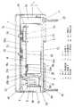
また、ボディ2の裏面の長手方向中央部には、図1に示すようにタイムスイッチのケース1をDINレール(図示せず)に取付けるための取付溝2jが幅方向(図1中の前後方向)に沿って設けられており、さらにボディ2の裏面の長手方向一端側(図1中の左側)には、レール取付具8が取付けられている。また、取付溝2jにおいてレール取付具8と反対側の端縁には、内側に向かって突出する係止突部2lが一体に設けられている。  Further, as shown in FIG. 1, anattachment groove 2j for attaching thecase 1 of the time switch to a DIN rail (not shown) is provided in the width direction (front-rear direction in FIG. 1). Further, arail attachment 8 is attached to one end of the back surface of thebody 2 in the longitudinal direction (left side in FIG. 1). In addition, a locking projection 2l that protrudes inward is integrally provided at the end of the mountinggroove 2j opposite to therail mounting tool 8.

レール取付具8は例えば合成樹脂成形品であって、図1及び図4に示すように縦長の略I字状の主片8dを有し、主片8dの先端側には主片8dと交差する方向に延出するばね体8cが一体に設けられている。このレール取付具8は、ボディ2の底面に設けられた溝(図示せず)内に主片8dを挿通させることでボディ2に取付けられ、主片8dはこの溝に沿って、取付溝2j内に挿入され取付溝2jの底面との間でDINレールの一方の係止片を挟持してDINレールを保持する保持位置と、取付溝2j内から後退してDINレールの保持を解除する解除位置との間で進退自在に移動できるようになっている。  Therail fixture 8 is, for example, a synthetic resin molded product, and has a vertically long substantially I-shapedmain piece 8d as shown in FIGS. 1 and 4, and intersects themain piece 8d at the front end side of themain piece 8d. A spring body 8c extending in the direction to be integrated is integrally provided. Therail attachment 8 is attached to thebody 2 by inserting themain piece 8d through a groove (not shown) provided on the bottom surface of thebody 2, and themain piece 8d extends along the groove along theattachment groove 2j. A holding position for holding the DIN rail by sandwiching one locking piece of the DIN rail with the bottom surface of the mountinggroove 2j inserted therein, and a release for retreating from the mountinggroove 2j and releasing the holding of the DIN rail It can move freely between positions.

而して、ケース1をDINレールに取付ける場合には、DINレールの幅方向一端側の係止片を取付溝2jの底面と係止突部2lとの間に差し込んだ状態で他端側の係止片を主片8dの先端部8bに当接させながらDINレールを取付溝2j側に押し込むと、DINレールからの押圧力により主片8dが外側(図1中の左側)に移動するとともにばね体8cが外側に付勢され、さらにDINレールを押込んで他端側の係止片が取付溝2jの底面と主片8dの先端部8bとの間に配置されると、ばね体8cからの反力(図1中の右方向の力)により主片8dが内側(図1中の右側)に移動し、DINレールの他端側の係止片が取付溝2jの底面と主片8dの先端部8bとの間に挟持されて、ケース1がDINレールに取付けられる。  Thus, when thecase 1 is attached to the DIN rail, the engaging piece on the one end side in the width direction of the DIN rail is inserted between the bottom surface of the attachinggroove 2j and the engaging protrusion 2l. When the DIN rail is pushed into the mountinggroove 2j while the locking piece is in contact with thetip 8b of themain piece 8d, themain piece 8d is moved outward (left side in FIG. 1) by the pressing force from the DIN rail. When the spring body 8c is urged outward, and the DIN rail is further pushed in and the other end side locking piece is disposed between the bottom surface of the mountinggroove 2j and thetip 8b of themain piece 8d, the spring body 8c 1 (the rightward force in FIG. 1) causes themain piece 8d to move inward (right side in FIG. 1), and the locking piece on the other end of the DIN rail is the bottom surface of the mountinggroove 2j and themain piece 8d. And thecase 1 is attached to the DIN rail.

逆に、ケース1をDINレールから取り外す場合には、ばね体8cからの反力に抗してレール取付具8を取付溝2j内から後退(図1中の左側に移動)させると、上記他端側の係止片の挟持状態が解除されて、DINレールからケース1が取り外される。  On the contrary, when removing thecase 1 from the DIN rail, if therail fixture 8 is moved backward (moved to the left in FIG. 1) from the inside of the mountinggroove 2j against the reaction force from the spring body 8c, The clamping state of the end side locking piece is released, and thecase 1 is removed from the DIN rail.

また、レール取付具8の主片8dには、図4に示すように下端側(先端部8bと反対側)に固定ねじ25が挿通されるねじ挿通孔8aが設けられており、このねじ挿通孔8aと上述したボディ2のねじ挿通孔2cにそれぞれ挿通した固定ねじ25、25を用いて被取付部にねじ固定することもできる。ここにおいて、レール取付具8は、図2及び図3に示すように組立状態においてケース1の下側の側面から外側へ突出しないように、ねじ挿通孔8aが設けられた部位をねじ挿通凹部9b、ねじ挿通凹部2a及びねじ挿通凹部3cで構成されるねじ挿通凹部内に配置している。  Further, as shown in FIG. 4, themain piece 8d of therail fixture 8 is provided with ascrew insertion hole 8a through which the fixingscrew 25 is inserted on the lower end side (the side opposite to thetip portion 8b). It is also possible to fix the screw to the attached portion by using the fixing screws 25, 25 respectively inserted into thehole 8a and thescrew insertion hole 2c of thebody 2 described above. Here, as shown in FIGS. 2 and 3, therail attachment 8 has ascrew insertion recess 9 b at a portion where thescrew insertion hole 8 a is provided so as not to protrude outward from the lower side surface of thecase 1 in the assembled state. Thescrew insertion recess 2a and thescrew insertion recess 3c are arranged in a screw insertion recess.

而して、本実施形態のタイムスイッチでは、レール取付具8がケース1の側面から外側へ出っ張ることがなく、タイムスイッチを梱包する包装箱の展開面積を小さくすることができるので、包装箱の材料費用を低減できるとともに省資源化に寄与することができる。また、レール取付具8がケース1の側面から外側へ突出していないので、タイムスイッチを梱包した包装箱を落下させた場合でも、従来例のようにレール取付具8がケース1から外れたり、レール取付具8やケース1の一部が破損することがなく、さらにレール取付具8の端部によって包装箱が引き裂かれレール取付具8の一部が露出することがない。さらに、従来例のように包装箱を補強したり、空きスペースに保護部材を入れる必要がないので、包装箱の補強や保護部材にかかる費用が不要になり、また保護部材の手配や在庫管理や収納作業などの費用も発生しないので、コストアップを抑えることができる。また、レール取付具8をケース1に取付けた状態で出荷できるため、タイムスイッチの取付時においてレール取付具8をケース1に取付ける作業を省くことができ、またレール取付具8を紛失することがない。  Thus, in the time switch of the present embodiment, therail attachment 8 does not protrude from the side surface of thecase 1 and the development area of the packaging box for packing the time switch can be reduced. Material costs can be reduced and resources can be saved. Further, since therail fixture 8 does not protrude outward from the side surface of thecase 1, even when the packaging box packed with the time switch is dropped, therail fixture 8 can be detached from thecase 1 as in the conventional example, Thefixture 8 and part of thecase 1 are not damaged, and the packaging box is torn by the end of therail fixture 8 so that therail fixture 8 is not partially exposed. Furthermore, since there is no need to reinforce the packaging box or put a protective member in the empty space as in the conventional example, the cost for reinforcing the packaging box and the protective member becomes unnecessary, and the arrangement of the protective member, inventory management, etc. Costs such as storage work are not incurred, so cost increases can be suppressed. In addition, since therail fixture 8 can be shipped with thecase 1 attached, it is possible to omit the work of attaching therail fixture 8 to thecase 1 when the time switch is attached, and therail fixture 8 can be lost. Absent.

カバー3は、上下方向及び左右方向の寸法がボディ2と略同寸法に形成された略矩形箱状の合成樹脂成形品であって、ボディ2に被着することでボディ2とともにケース1を形成する。カバー3の長手方向一端側(図4中の上側)には、ボディ2のねじ挿通孔2cと連通するねじ挿通孔3aが設けられ、カバー3の前面においてねじ挿通孔3aの下側には、操作部表示シート7が取付けられる略矩形状の取付凹所3lが設けられている。また、取付凹所3lの底面において液晶表示部12に対応する部位には、液晶表示部12の表示内容を前方から視認可能とする略矩形状の開口窓3dが設けられ、この開口窓3dの下側には設定用スイッチ部13を構成する各プッシュ型ボタンの操作部を前面側に露出させる複数の孔からなる露出部3eが設けられている。また、開口窓3d及び露出部3eの右側には、出力状態表示部14a及び通電状態表示部14bに対応する部位にLEDからの光を前面側に露光するための露光窓3f、3hがそれぞれ設けられるとともに、動作設定スイッチ15及びモード切替スイッチ16に対応する部位に各スイッチの操作部に取付けられる摘み18を配置する溝3g、3jがそれぞれ設けられ、溝3g、3jの底部には各スイッチの操作部を前面側に露出させる露出孔が貫設されている。これらの露光窓3f、3h及び溝3g、3jは、取付凹所3l内において上下方向に並んで設けられている。尚、摘み18は、各スイッチの操作性を向上させるために取付けられるものであり、溝3g、3j内に上下方向に移動自在に配置される。ここに、ボディ2のねじ挿通孔2c及びカバー3のねじ挿通孔3aでねじ挿通部が構成されている。  Thecover 3 is a substantially rectangular box-shaped synthetic resin molded product whose vertical and horizontal dimensions are approximately the same as those of thebody 2, and is attached to thebody 2 to form thecase 1 together with thebody 2. To do. Ascrew insertion hole 3a communicating with thescrew insertion hole 2c of thebody 2 is provided on one end side in the longitudinal direction of the cover 3 (upper side in FIG. 4), and on the front side of thecover 3 below thescrew insertion hole 3a, A substantially rectangular mounting recess 3l to which the operationsection display sheet 7 is mounted is provided. In addition, a substantiallyrectangular opening window 3d that allows the display contents of the liquidcrystal display unit 12 to be visually recognized from the front is provided at a portion corresponding to the liquidcrystal display unit 12 on the bottom surface of the mounting recess 3l. On the lower side, there is provided an exposedportion 3e composed of a plurality of holes for exposing the operation portion of each push type button constituting the settingswitch portion 13 to the front side. Further, on the right side of theopening window 3d and the exposedportion 3e,exposure windows 3f and 3h for exposing light from the LED to the front side are provided at portions corresponding to the outputstate display portion 14a and the energizationstate display portion 14b, respectively. In addition,grooves 3g and 3j are provided at positions corresponding to theoperation setting switch 15 and themode changeover switch 16 to disposeknobs 18 attached to the operation portions of the respective switches. An exposure hole for exposing the operation unit to the front side is provided. Theseexposure windows 3f and 3h andgrooves 3g and 3j are provided side by side in the vertical direction in the mounting recess 3l. Theknob 18 is attached to improve the operability of each switch, and is arranged in thegrooves 3g and 3j so as to be movable in the vertical direction. Here, a screw insertion portion is constituted by thescrew insertion hole 2 c of thebody 2 and thescrew insertion hole 3 a of thecover 3.

さらに、カバー3の長手方向他端側(図4中の下側)には、端子台ブロック6を露出するための切欠部3bが設けられ、切欠部3bの上部には各端子の名称(本実施形態では、電源及び負荷)が記載されたネームプレート27が取付けられている。また、カバー3の長手方向他端側において幅方向中央部には、側壁を内側に略コ字型に折り曲げて形成され、端子台9に設けたねじ挿通凹部9b及びボディ2に設けたねじ挿通凹部2aと連通するねじ挿通凹部3cが設けられている。さらに、カバー3の長手方向に沿う両側壁においてボディ2に設けた嵌合突起2dに対応する部位には、嵌合突起2dが嵌合する嵌合孔3kが設けられており、ボディ2の前面側からカバー3を被着するとともに、各嵌合突起2dを対応する嵌合孔3kにそれぞれ嵌合させることでケース1が組立てられる。  Further, anotch 3b for exposing theterminal block 6 is provided on the other end in the longitudinal direction of the cover 3 (the lower side in FIG. 4), and the name of each terminal (book) is provided above thenotch 3b. In the embodiment, aname plate 27 on which a power source and a load are described is attached. Further, at the other end in the longitudinal direction of thecover 3, ascrew insertion recess 9 b provided in theterminal block 9 and a screw insertion provided in thebody 2 are formed by bending the side wall into a substantially U shape at the center in the width direction. Ascrew insertion recess 3c communicating with therecess 2a is provided. Further, on both side walls along the longitudinal direction of thecover 3, a portion corresponding to thefitting projection 2d provided on thebody 2 is provided with afitting hole 3k into which thefitting projection 2d is fitted. Thecover 3 is attached from the side, and thecase 1 is assembled by fitting eachfitting projection 2d into the correspondingfitting hole 3k.

操作部表示シート7は、例えばアクリル樹脂などにより略矩形状に形成され、液晶表示部12、出力状態表示部14a及び通電状態表示部14bに対応する部位には表示内容やLEDからの光が前面側から視認できるように透明部7a、7bがそれぞれ設けられている。また、設定用スイッチ部13、動作設定スイッチ15及びモード切替スイッチ16に対応する部位には、各スイッチの操作部を露出させる露出孔7c、7dが設けられており、さらに透明部7b、露出孔7c、7dの近傍には、各スイッチのモードやLEDの表示対象などを示す文字列26が例えば印刷により形成されている。この操作部表示シート7は、取付凹所3l内に配置された状態でカバー3に固着され、上記摘み18はこの操作部表示シート7とカバー3との間に挟まれた状態で溝3g、3j内に配置される。  The operationunit display sheet 7 is formed in a substantially rectangular shape using, for example, an acrylic resin, and the display content and light from the LEDs are on the front surface at the portions corresponding to the liquidcrystal display unit 12, the outputstate display unit 14a, and the energizationstate display unit 14b.Transparent portions 7a and 7b are provided so as to be visible from the side. Further, exposure holes 7c and 7d for exposing the operation parts of the respective switches are provided in portions corresponding to the settingswitch part 13, theoperation setting switch 15 and themode change switch 16, and further, thetransparent part 7b and the exposure hole are provided. In the vicinity of 7c and 7d, acharacter string 26 indicating the mode of each switch, LED display target, and the like is formed by printing, for example. The operationportion display sheet 7 is fixed to thecover 3 in a state where the operationportion display sheet 7 is disposed in the mounting recess 3l, and theknob 18 is provided between the operationportion display sheet 7 and thecover 3 in a state where thegroove 3g, 3j.

カバー3の切欠部3bには、図2及び図3に示すように電源接続端子36、36及び負荷接続端子37、37を覆う端子カバー40が開閉自在に取付けられる。この端子カバー40は、略L字状に形成されたカバー本体40aを有し、カバー本体40aの裏面側において長手方向(図3中の左右方向)中央部には、主片40aに設けたねじ挿通孔40dと連通する略円筒状のねじ挿通部40cが一体に設けられ、さらにねじ挿通部40cを間にして長手方向両側には、リブ40b、40bが突設されている。  As shown in FIGS. 2 and 3, aterminal cover 40 that covers thepower connection terminals 36 and 36 and theload connection terminals 37 and 37 is attached to thenotch 3b of thecover 3 so as to be freely opened and closed. Thisterminal cover 40 has a covermain body 40a formed in a substantially L shape, and a screw provided on themain piece 40a at the center in the longitudinal direction (left-right direction in FIG. 3) on the back side of the covermain body 40a. A substantially cylindricalscrew insertion portion 40c that communicates with theinsertion hole 40d is integrally provided, andribs 40b and 40b project from both sides in the longitudinal direction with thescrew insertion portion 40c therebetween.

この端子カバー40は、長手方向両端縁にそれぞれ設けた軸突起(図示せず)をカバー3の切欠部3bの両端部に形成した軸孔(図示せず)にそれぞれ軸支することによって開閉自在にカバー3に取付けられ、ねじ挿通孔40dを通してねじ挿通部40cに挿通した固定ねじ41を端子台9に設けたねじ孔9dに螺合させると、図2に示すように端子カバー40が端子台9に固定される。この状態において、ねじ挿通凹部(ねじ挿通凹部2a、3c及び9b)は端子カバー40により覆われており、前面側から見えないようになっている。  Theterminal cover 40 can be opened and closed by axially supporting shaft projections (not shown) provided at both ends in the longitudinal direction in shaft holes (not shown) formed at both ends of thenotch 3b of thecover 3, respectively. When the fixingscrew 41 attached to thecover 3 and inserted into thescrew insertion portion 40c through thescrew insertion hole 40d is screwed into thescrew hole 9d provided in theterminal block 9, theterminal cover 40 is attached to the terminal block as shown in FIG. 9 is fixed. In this state, the screw insertion recesses (screwinsertion recesses 2a, 3c, and 9b) are covered with theterminal cover 40 and are not visible from the front side.

而して、本実施形態のタイムスイッチでは、ねじ挿通凹部が前面側から見えないように端子カバー40で覆われているので、タイムスイッチを固定ねじ25を用いて被取付部に取付ける場合、ねじ挿通凹部内に配置されたレール取付具8や固定ねじ25が前面側から見えることがなく、外観を向上させたタイムスイッチを提供することができる。  Thus, in the time switch of the present embodiment, the screw insertion recess is covered with theterminal cover 40 so that it cannot be seen from the front side. Therefore, when the time switch is attached to the attached portion using the fixingscrew 25, the screw Therail switch 8 and the fixingscrew 25 arranged in the insertion recess are not seen from the front side, and a time switch with improved appearance can be provided.

また、カバー3の前面側には、図1に示すように前面カバー22が取付けられる。この前面カバー22は下面が開口する略矩形箱状であって、例えば透明なアクリル樹脂などにより形成されており、前面カバー22をカバー3に取付けた状態でも液晶表示部12の表示内容や各スイッチの設定状態などが確認できるようになっている。  Afront cover 22 is attached to the front side of thecover 3 as shown in FIG. Thefront cover 22 has a substantially rectangular box shape with an open bottom surface, and is formed of, for example, a transparent acrylic resin. Even when thefront cover 22 is attached to thecover 3, the display contents of the liquidcrystal display unit 12 and each switch You can check the setting status.

ここで、タイムスイッチの組立手順について図3及び図4に基づいて説明する。まず、ボディ2の底面にレール取付具8を取付けるとともに、基板本体38aが基板収納部2h側、端子台ブロック6が端子台収納部2b、2b側となるように前面側から基板ブロック4をボディ2内に収納する。この時、端子台9は両側壁に設けた嵌合突起9eがそれぞれ対応する嵌合部2kの嵌合孔に嵌合してボディ2に固定され、基板本体38aは4つの基板受け部2eの当接面(上面)と当接する。次に、カバー3を前面側からボディ2に被着するとともにボディ2の各嵌合突起2dを対応するカバー3の嵌合孔3kに嵌合させてケース1を組立てる。この時、液晶表示部12は開口窓3dを臨んだ状態で配置され、設定用スイッチ部13の各プッシュ型ボタンは操作部を露出部3eの対応する孔からそれぞれ露出させた状態で配置される。また、出力状態表示部14a及び通電状態表示部14bは、それぞれ露光窓3f、3hを臨んだ状態で配置されるとともに、動作設定スイッチ15及びモード切替スイッチ16は操作部を溝3g、3jと連通する露出孔からそれぞれ露出させた状態で配置され、さらに端子台ブロック6はカバー3の切欠部3bを臨んだ状態で配置される。さらに、基板本体38aは、カバー3の内側面に設けた複数の基板押さえ部(図示せず)の下面と、ボディ2に設けた基板受け部2eの当接面との間で挟持される。最後に、各摘み18をそれぞれ対応するスイッチの操作部に取付けるとともに溝3g、3j内に配置し、前面側から操作部表示シート7をカバー3の取付凹所3l内に固着した後、端子カバー40をカバー3に軸支すると、タイムスイッチの組立てが完了する。  Here, the assembly procedure of the time switch will be described with reference to FIGS. First, therail fixture 8 is attached to the bottom surface of thebody 2, and theboard block 4 is mounted from the front side so that theboard body 38a is on theboard housing part 2h side and theterminal block 6 is on the terminalboard housing parts 2b and 2b side. 2 to store. At this time, theterminal block 9 is fixed to thebody 2 with the fitting protrusions 9e provided on both side walls fitted in the fitting holes of the correspondingfitting portions 2k, and thesubstrate body 38a is formed of the foursubstrate receiving portions 2e. Abuts against the abutment surface (upper surface). Next, thecover 3 is attached to thebody 2 from the front side, and thefitting protrusions 2d of thebody 2 are fitted into thefitting holes 3k of thecorresponding cover 3 to assemble thecase 1. At this time, the liquidcrystal display unit 12 is arranged in a state of facing theopening window 3d, and each push-type button of the settingswitch unit 13 is arranged in a state in which the operation unit is exposed from the corresponding hole of theexposure unit 3e. . The outputstate display unit 14a and the energizationstate display unit 14b are arranged with theexposure windows 3f and 3h facing, respectively, and theoperation setting switch 15 and themode switch 16 communicate the operation unit with thegrooves 3g and 3j. Theterminal block 6 is arranged in a state of facing thenotch 3 b of thecover 3. Further, thesubstrate body 38 a is sandwiched between the lower surfaces of a plurality of substrate pressing portions (not shown) provided on the inner side surface of thecover 3 and the contact surfaces of thesubstrate receiving portions 2 e provided on thebody 2. Finally, eachknob 18 is attached to the corresponding switch operating portion and disposed in thegrooves 3g, 3j, and the operationportion display sheet 7 is fixed in the mounting recess 3l of thecover 3 from the front side. When 40 is pivotally supported on thecover 3, the assembly of the time switch is completed.

さらに、組立てられたタイムスイッチはDINレールに取付けられたり、固定ねじ25を用いて被取付部に取付けられ、電源線や負荷Lからの電線(ともに図示せず)がカバー3の切欠部3bを通して端子台ブロック6の電源接続端子36、36及び負荷接続端子37、37にそれぞれ接続される。そして、端子カバー40を固定ねじ41を用いて端子台9に螺着し、前面カバー22をカバー3に被着するとタイムスイッチの取付けが完了する。  Further, the assembled time switch is attached to the DIN rail or attached to the attached portion using the fixingscrew 25, and the power line and the electric wire from the load L (both not shown) pass through thenotch 3b of thecover 3. The powersupply connection terminals 36 and 36 and theload connection terminals 37 and 37 of theterminal block 6 are respectively connected. Then, when theterminal cover 40 is screwed to theterminal block 9 using the fixing screws 41 and thefront cover 22 is attached to thecover 3, the time switch is completely attached.

次に、タイムスイッチによる負荷Lの制御動作について図6に基づいて説明する。制御部17が動作を開始すると(ステップS1)、時計部31により現在時刻の計時動作を行わせた後(ステップS2)、制御部17は動作設定スイッチ15のスライド操作によって設定された動作が自動動作であるか否かを判定する(ステップS3)。ステップS3において自動動作であると判定した場合には、制御部17はプログラム記憶部33に記憶されたプログラムで設定した曜日及び時刻と、現在の曜日及び時刻とを比較し(ステップS4)、現在の曜日及び時刻が設定された曜日及び時刻に一致すると制御部17は出力部19に対してオン/オフ指令を出力し、このオン/オフ指令に基づいて出力部19が負荷Lをオン/オフさせる(ステップS5)。  Next, the control operation of the load L by the time switch will be described based on FIG. When the control unit 17 starts the operation (step S1), after theclock unit 31 performs the current time measuring operation (step S2), the control unit 17 automatically performs the operation set by the slide operation of theoperation setting switch 15. It is determined whether or not it is an operation (step S3). If it is determined in step S3 that the operation is automatic, the control unit 17 compares the day of the week and time set by the program stored in theprogram storage unit 33 with the current day of the week and time (step S4), When the day of the week and time coincide with the set day of the week and time, the control unit 17 outputs an on / off command to the output unit 19, and the output unit 19 turns on / off the load L based on the on / off command. (Step S5).

また、ステップS3において自動動作でないと判定した場合には、制御部17は動作設定スイッチ15のスライド操作によって設定された動作が連続入動作または連続切動作であるかを判定する(ステップS6)。ステップS6において連続入動作または連続切動作であると判定した場合には、制御部17はプログラムに関係なく出力部19に対して連続的にオン/オフ指令を出力し、このオン/オフ指令に基づいて出力部19が負荷Lを連続的にオン/オフさせる(ステップS7)。  When it is determined in step S3 that the operation is not an automatic operation, the control unit 17 determines whether the operation set by the slide operation of theoperation setting switch 15 is a continuous on operation or a continuous cut operation (step S6). When it is determined in step S6 that the operation is the continuous input operation or the continuous cut operation, the control unit 17 continuously outputs an on / off command to the output unit 19 regardless of the program. Based on this, the output unit 19 continuously turns on / off the load L (step S7).

さらに、ステップS6において連続入動作または連続切動作の何れでもないと判定した場合には、制御部17は動作設定スイッチ15のスライド操作によって設定された動作が手動一時入動作または手動一時切動作であるかを判定する(ステップS8)。ステップS8において手動一時入動作または手動一時切動作であると判定した場合には、制御部17はプログラムに関係なく出力部19に対して一時的にオン/オフ指令を出力し、このオン/オフ指令に基づいて出力部19が負荷Lを一時的にオン/オフさせる(ステップS9)。  Further, when it is determined in step S6 that neither the continuous input operation nor the continuous cut operation is performed, the control unit 17 determines that the operation set by the slide operation of theoperation setting switch 15 is a manual temporary input operation or a manual temporary cut operation. It is determined whether or not there is (step S8). If it is determined in step S8 that the operation is a manual temporary turning-on operation or a manual temporary turning-off operation, the control unit 17 temporarily outputs an on / off command to the output unit 19 regardless of the program, and this on / off operation is performed. Based on the command, the output unit 19 temporarily turns on / off the load L (step S9).

そして、負荷Lの制御動作が終了すると、計時動作に戻り(ステップS2)、以降、上記ステップS2〜S9を繰り返して負荷Lの動作制御を行う。  Then, when the control operation of the load L is completed, the operation returns to the time measuring operation (step S2), and thereafter, the operation control of the load L is performed by repeating the above steps S2 to S9.

尚、本実施形態では、電気機器としてタイムスイッチを例に説明したが、DINレールに取付けられるような電気機器であればよく、例えば回路遮断器のようなものであってもよい。  In the present embodiment, the time switch has been described as an example of the electric device. However, any electric device that can be attached to the DIN rail may be used. For example, a circuit breaker may be used.

本実施形態の電気機器の断面図である。It is sectional drawing of the electric equipment of this embodiment.同上の端子カバーを閉じた状態の斜視図である。It is a perspective view of the state which closed the terminal cover same as the above.同上の端子カバーを開けた状態の斜視図である。It is a perspective view of the state which opened the terminal cover same as the above.同上の分解斜視図である。It is an exploded perspective view same as the above.同上に用いられる基板に形成されたタイマ回路のブロック図である。It is a block diagram of the timer circuit formed in the board | substrate used for the same as the above.同上の負荷の制御動作を示すフローチャート図である。It is a flowchart figure which shows the control operation of load same as the above.

符号の説明Explanation of symbols

1 ケース(器体)
2 ボディ
2a ねじ挿通凹部
2c ねじ挿通部
2j 取付溝
3 カバー
3a ねじ挿通部
3c ねじ挿通凹部
8 レール取付具
8a ねじ挿通孔
9b ねじ挿通凹部
1 Case (container)
2Body 2aScrew insertion recess 2cScrew insertion portion2j Mounting groove 3Cover 3aScrew insertion portion 3cScrew insertion recess 8Rail attachment 8aScrew insertion hole 9b Screw insertion recess

Claims (3)

Translated fromJapanese
少なくとも幅方向の両側縁からそれぞれ外向きに係止片が延設されたレールが嵌入されるレール取付溝が形成された器体と、レール取付溝内に挿入され当該レール取付溝の底面との間でレールの一方の係止片を挟持してレールを保持する保持位置とレール取付溝内から後退してレールの保持を解除する解除位置との間で進退自在に器体に取付けられたレール取付具とを備え、器体の一端側には当該器体を被取付部に取付けるための取付ねじが挿通されるねじ挿通部が器体の厚み方向に貫設されるとともに、器体の他端側には取付ねじが挿通されるねじ挿通凹部が一側面の一部に凹設され、レール取付具の一端側にはねじ挿通凹部内に挿入された取付ねじが挿通されるねじ挿通孔が設けられ、当該レール取付具は、器体の一側面から突出しないように、ねじ挿通孔が設けられた部位をねじ挿通凹部内に配置したことを特徴とする電気機器。  A container having a rail mounting groove into which a rail having a locking piece extending outward from at least both side edges in the width direction is formed, and a bottom surface of the rail mounting groove inserted into the rail mounting groove. A rail that is attached to the body so that it can be moved forward and backward between a holding position for holding the rail by sandwiching one of the locking pieces between it and a release position for retreating from the rail mounting groove to release the holding of the rail A screw insertion portion through which a mounting screw for attaching the device body to the attached portion is inserted in the thickness direction of the device body. A screw insertion recess into which the mounting screw is inserted is formed in a part of one side surface on the end side, and a screw insertion hole into which the mounting screw inserted into the screw insertion recess is inserted on one end side of the rail fixture. Provided, the rail fixture does not protrude from one side of the vessel Sea urchin, electrical equipment, characterized in that a portion screw insertion hole is provided in the screw insertion recess. 少なくとも現在時刻を計時する時計手段と、所望の時刻に負荷を制御するためのプログラムを設定するプログラム設定手段と、少なくとも現在時刻を表示する表示手段と、電源が接続される電源接続端子と、負荷が接続される負荷接続端子と、電源接続端子及び負荷接続端子と直列に接続されて負荷への電源供給をオン/オフする開閉手段と、現在時刻が所望の時刻と一致した際に開閉手段をオン/オフする制御信号を出力する出力制御手段とを備え、電源接続端子及び負荷接続端子は前記器体の他端側の側部に並べて配置され、当該電源接続端子と負荷接続端子との間に前記ねじ挿通凹部を設けたことを特徴とする請求項1記載の電気機器。  Clock means for measuring at least the current time, program setting means for setting a program for controlling the load at a desired time, display means for displaying at least the current time, a power connection terminal to which a power source is connected, a load A load connection terminal connected to the power supply terminal, a switching means connected in series with the power connection terminal and the load connection terminal to turn on / off power supply to the load, and a switching means when the current time coincides with a desired time. Output control means for outputting a control signal for turning on / off, and the power connection terminal and the load connection terminal are arranged side by side on the other end side of the container, and between the power connection terminal and the load connection terminal. The electric device according to claim 1, wherein the screw insertion concave portion is provided in the electric device. 前記ねじ挿通凹部を覆うカバーを設けたことを特徴とする請求項1又は2の何れか1項に記載の電気機器。  The electrical apparatus according to claim 1, wherein a cover that covers the screw insertion recess is provided.
JP2007219042A2007-08-242007-08-24 Electrical equipmentActiveJP4934778B2 (en)

Priority Applications (1)

Application NumberPriority DateFiling DateTitle
JP2007219042AJP4934778B2 (en)2007-08-242007-08-24 Electrical equipment

Applications Claiming Priority (1)

Application NumberPriority DateFiling DateTitle
JP2007219042AJP4934778B2 (en)2007-08-242007-08-24 Electrical equipment

Publications (2)

Publication NumberPublication Date
JP2009052987A JP2009052987A (en)2009-03-12
JP4934778B2true JP4934778B2 (en)2012-05-16

Family

ID=40504198

Family Applications (1)

Application NumberTitlePriority DateFiling Date
JP2007219042AActiveJP4934778B2 (en)2007-08-242007-08-24 Electrical equipment

Country Status (1)

CountryLink
JP (1)JP4934778B2 (en)

Family Cites Families (4)

* Cited by examiner, † Cited by third party
Publication numberPriority datePublication dateAssigneeTitle
IT1179808B (en)*1984-10-311987-09-16Hospal Dasco Spa DETECTION AND CONTROL EQUIPMENT FOR THE PRESENCE OF A GASEOUS FLUID IN CORRESPONDENCE WITH A PREFIXED LEVEL OF A LIQUID CONTAINER
JPS62160421A (en)*1986-01-081987-07-16Shinto Paint Co LtdMethod for forming functional coated film between fine conductive circuits
JPH0432584A (en)*1990-05-291992-02-04Furukawa Alum Co LtdProduction of aluminum alloy sheet usable for can body
JP4504745B2 (en)*2004-06-182010-07-14パナソニック電工株式会社 Program time switch

Also Published As

Publication numberPublication date
JP2009052987A (en)2009-03-12

Similar Documents

PublicationPublication DateTitle
PT1404170E (en)Combination of apparatus
RU2413130C2 (en)Electric appliance comprising suspension facilities installed on bracket of instrument
JP4934778B2 (en) Electrical equipment
US6429547B1 (en)Time switch
JP4881261B2 (en) Time switch
JP4931146B2 (en) Time switch
JP5816862B2 (en) Switch device
JP2010055844A (en)Ventilation fan switch
JP4981621B2 (en) Photoelectric flasher
JPH10326541A (en)Switch and switch device using it
US6429549B1 (en)Time switch
KR100881362B1 (en) A breaker
JP6355044B2 (en) Dimming switch
WO2016113800A1 (en)Push-button switch device, radio wave transmitter and lighting control system
JP7555050B2 (en) Circuit breakers and distribution boards
JPH1186682A (en)Switch and switch apparatus using the switch
KR101175559B1 (en)Fixing apparatus for lamp in refrigerator
KR101030715B1 (en) Switch device
JP3124038U (en) Remote control device
JP2017034864A (en)Power distribution board
JPH038054B2 (en)
JP6490165B2 (en) Remote receiver
JP4533131B2 (en) Operation board
KR200371938Y1 (en)A Holder of Fuse
JP2007014160A (en)Distribution panel

Legal Events

DateCodeTitleDescription
A621Written request for application examination

Free format text:JAPANESE INTERMEDIATE CODE: A621

Effective date:20100112

A977Report on retrieval

Free format text:JAPANESE INTERMEDIATE CODE: A971007

Effective date:20110815

A131Notification of reasons for refusal

Free format text:JAPANESE INTERMEDIATE CODE: A131

Effective date:20110830

TRDDDecision of grant or rejection written
A01Written decision to grant a patent or to grant a registration (utility model)

Free format text:JAPANESE INTERMEDIATE CODE: A01

Effective date:20111220

A01Written decision to grant a patent or to grant a registration (utility model)

Free format text:JAPANESE INTERMEDIATE CODE: A01

A61First payment of annual fees (during grant procedure)

Free format text:JAPANESE INTERMEDIATE CODE: A61

Effective date:20120113

FPAYRenewal fee payment (event date is renewal date of database)

Free format text:PAYMENT UNTIL: 20150302

Year of fee payment:3

R150Certificate of patent or registration of utility model

Ref document number:4934778

Country of ref document:JP

Free format text:JAPANESE INTERMEDIATE CODE: R150

Free format text:JAPANESE INTERMEDIATE CODE: R150

R250Receipt of annual fees

Free format text:JAPANESE INTERMEDIATE CODE: R250

R250Receipt of annual fees

Free format text:JAPANESE INTERMEDIATE CODE: R250

R250Receipt of annual fees

Free format text:JAPANESE INTERMEDIATE CODE: R250

R250Receipt of annual fees

Free format text:JAPANESE INTERMEDIATE CODE: R250

R250Receipt of annual fees

Free format text:JAPANESE INTERMEDIATE CODE: R250

R250Receipt of annual fees

Free format text:JAPANESE INTERMEDIATE CODE: R250

R250Receipt of annual fees

Free format text:JAPANESE INTERMEDIATE CODE: R250

R250Receipt of annual fees

Free format text:JAPANESE INTERMEDIATE CODE: R250

R250Receipt of annual fees

Free format text:JAPANESE INTERMEDIATE CODE: R250

R250Receipt of annual fees

Free format text:JAPANESE INTERMEDIATE CODE: R250

R250Receipt of annual fees

Free format text:JAPANESE INTERMEDIATE CODE: R250


[8]ページ先頭

©2009-2025 Movatter.jp