JP4933842B2 - Portable device for body fluid analysis - Google Patents
Portable device for body fluid analysisDownload PDFInfo
- Publication number
- JP4933842B2 JP4933842B2JP2006162130AJP2006162130AJP4933842B2JP 4933842 B2JP4933842 B2JP 4933842B2JP 2006162130 AJP2006162130 AJP 2006162130AJP 2006162130 AJP2006162130 AJP 2006162130AJP 4933842 B2JP4933842 B2JP 4933842B2
- Authority
- JP
- Japan
- Prior art keywords
- incision
- instrument
- imparting
- wound
- analytical instrument
- Prior art date
- Legal status (The legal status is an assumption and is not a legal conclusion. Google has not performed a legal analysis and makes no representation as to the accuracy of the status listed.)
- Expired - Fee Related
Links
Images


Classifications
- A—HUMAN NECESSITIES
- A61—MEDICAL OR VETERINARY SCIENCE; HYGIENE
- A61B—DIAGNOSIS; SURGERY; IDENTIFICATION
- A61B5/00—Measuring for diagnostic purposes; Identification of persons
- A61B5/15—Devices for taking samples of blood
- A61B5/151—Devices specially adapted for taking samples of capillary blood, e.g. by lancets, needles or blades
- A61B5/15146—Devices loaded with multiple lancets simultaneously, e.g. for serial firing without reloading, for example by use of stocking means.
- A61B5/15148—Constructional features of stocking means, e.g. strip, roll, disc, cartridge, belt or tube
- A61B5/15157—Geometry of stocking means or arrangement of piercing elements therein
- A61B5/15159—Piercing elements stocked in or on a disc
- A61B5/15163—Characterized by propelling the piercing element in an axial direction relative to the disc
- A—HUMAN NECESSITIES
- A61—MEDICAL OR VETERINARY SCIENCE; HYGIENE
- A61B—DIAGNOSIS; SURGERY; IDENTIFICATION
- A61B5/00—Measuring for diagnostic purposes; Identification of persons
- A61B5/145—Measuring characteristics of blood in vivo, e.g. gas concentration or pH-value ; Measuring characteristics of body fluids or tissues, e.g. interstitial fluid or cerebral tissue
- A61B5/1468—Measuring characteristics of blood in vivo, e.g. gas concentration or pH-value ; Measuring characteristics of body fluids or tissues, e.g. interstitial fluid or cerebral tissue using chemical or electrochemical methods, e.g. by polarographic means
- A61B5/1486—Measuring characteristics of blood in vivo, e.g. gas concentration or pH-value ; Measuring characteristics of body fluids or tissues, e.g. interstitial fluid or cerebral tissue using chemical or electrochemical methods, e.g. by polarographic means using enzyme electrodes, e.g. with immobilised oxidase
- A—HUMAN NECESSITIES
- A61—MEDICAL OR VETERINARY SCIENCE; HYGIENE
- A61B—DIAGNOSIS; SURGERY; IDENTIFICATION
- A61B5/00—Measuring for diagnostic purposes; Identification of persons
- A61B5/15—Devices for taking samples of blood
- A61B5/150007—Details
- A61B5/150015—Source of blood
- A61B5/150022—Source of blood for capillary blood or interstitial fluid
- A—HUMAN NECESSITIES
- A61—MEDICAL OR VETERINARY SCIENCE; HYGIENE
- A61B—DIAGNOSIS; SURGERY; IDENTIFICATION
- A61B5/00—Measuring for diagnostic purposes; Identification of persons
- A61B5/15—Devices for taking samples of blood
- A61B5/150007—Details
- A61B5/150175—Adjustment of penetration depth
- A61B5/150198—Depth adjustment mechanism at the proximal end of the carrier of the piercing element
- A—HUMAN NECESSITIES
- A61—MEDICAL OR VETERINARY SCIENCE; HYGIENE
- A61B—DIAGNOSIS; SURGERY; IDENTIFICATION
- A61B5/00—Measuring for diagnostic purposes; Identification of persons
- A61B5/15—Devices for taking samples of blood
- A61B5/150007—Details
- A61B5/150374—Details of piercing elements or protective means for preventing accidental injuries by such piercing elements
- A61B5/150381—Design of piercing elements
- A61B5/150412—Pointed piercing elements, e.g. needles, lancets for piercing the skin
- A—HUMAN NECESSITIES
- A61—MEDICAL OR VETERINARY SCIENCE; HYGIENE
- A61B—DIAGNOSIS; SURGERY; IDENTIFICATION
- A61B5/00—Measuring for diagnostic purposes; Identification of persons
- A61B5/15—Devices for taking samples of blood
- A61B5/150007—Details
- A61B5/150374—Details of piercing elements or protective means for preventing accidental injuries by such piercing elements
- A61B5/150381—Design of piercing elements
- A61B5/150503—Single-ended needles
- A—HUMAN NECESSITIES
- A61—MEDICAL OR VETERINARY SCIENCE; HYGIENE
- A61B—DIAGNOSIS; SURGERY; IDENTIFICATION
- A61B5/00—Measuring for diagnostic purposes; Identification of persons
- A61B5/15—Devices for taking samples of blood
- A61B5/151—Devices specially adapted for taking samples of capillary blood, e.g. by lancets, needles or blades
- A61B5/15101—Details
- A61B5/15115—Driving means for propelling the piercing element to pierce the skin, e.g. comprising mechanisms based on shape memory alloys, magnetism, solenoids, piezoelectric effect, biased elements, resilient elements, vacuum or compressed fluids
- A61B5/15117—Driving means for propelling the piercing element to pierce the skin, e.g. comprising mechanisms based on shape memory alloys, magnetism, solenoids, piezoelectric effect, biased elements, resilient elements, vacuum or compressed fluids comprising biased elements, resilient elements or a spring, e.g. a helical spring, leaf spring, or elastic strap
- A—HUMAN NECESSITIES
- A61—MEDICAL OR VETERINARY SCIENCE; HYGIENE
- A61B—DIAGNOSIS; SURGERY; IDENTIFICATION
- A61B5/00—Measuring for diagnostic purposes; Identification of persons
- A61B5/15—Devices for taking samples of blood
- A61B5/151—Devices specially adapted for taking samples of capillary blood, e.g. by lancets, needles or blades
- A61B5/15101—Details
- A61B5/15126—Means for controlling the lancing movement, e.g. 2D- or 3D-shaped elements, tooth-shaped elements or sliding guides
- A61B5/15132—Means for controlling the lancing movement, e.g. 2D- or 3D-shaped elements, tooth-shaped elements or sliding guides comprising tooth-shaped elements, e.g. toothed wheel or rack and pinion
- A—HUMAN NECESSITIES
- A61—MEDICAL OR VETERINARY SCIENCE; HYGIENE
- A61B—DIAGNOSIS; SURGERY; IDENTIFICATION
- A61B5/00—Measuring for diagnostic purposes; Identification of persons
- A61B5/15—Devices for taking samples of blood
- A61B5/151—Devices specially adapted for taking samples of capillary blood, e.g. by lancets, needles or blades
- A61B5/15101—Details
- A61B5/15103—Piercing procedure
- A61B5/15107—Piercing being assisted by a triggering mechanism
Landscapes
- Health & Medical Sciences (AREA)
- Life Sciences & Earth Sciences (AREA)
- Physics & Mathematics (AREA)
- Molecular Biology (AREA)
- Animal Behavior & Ethology (AREA)
- Pathology (AREA)
- Engineering & Computer Science (AREA)
- Biomedical Technology (AREA)
- Heart & Thoracic Surgery (AREA)
- Medical Informatics (AREA)
- Veterinary Medicine (AREA)
- Surgery (AREA)
- Biophysics (AREA)
- General Health & Medical Sciences (AREA)
- Public Health (AREA)
- Hematology (AREA)
- Geometry (AREA)
- Chemical & Material Sciences (AREA)
- Chemical Kinetics & Catalysis (AREA)
- General Chemical & Material Sciences (AREA)
- Optics & Photonics (AREA)
- Dermatology (AREA)
- Measurement Of The Respiration, Hearing Ability, Form, And Blood Characteristics Of Living Organisms (AREA)
Description
Translated fromJapanese本願発明は体液の分析を実行するための携帯型分析機器に関するものであり、前記分析機器であって、それが身体の一部、より具体的には一本の指、を置くための開口部を有する本体容器、本体容器の前記開口部におかれた指に切開による傷口がつけられ、前記切開された傷口から流出し採取された体液を分析する分析器具、ランセットと、前記ランセットが切開傷をつくるために必要な高速度でランセットの運動を生起させるランセット発射機からなる切開傷付与器具、その収納位置と前記本体容器の開口部に置かれ前記開口部に押し付けられた身体の部分に前記ランセットにより切開傷をつける行為が実行される場所である切開動作位置とのあいだで、前記切開傷付与器具を位置移動させる輸送器具、切開傷付与器具の機械的構造を動作させる駆動器具から構成されることを特徴とするような携帯用分析機器は独国出願公開第10332488号明細書に開示されているとおり公知である。 The present invention relates to a portable analytical instrument for performing an analysis of body fluid, wherein the analytical instrument is an opening for placing a part of the body, more specifically, one finger. A body container, an analysis instrument for analyzing a collected body fluid flowing out from the incised wound, a lancet, and a lancet being an incision wound An incision imparting device comprising a lancet launcher that causes lancet motion at a high speed necessary to make the lancet, and the storage position and the body part placed in the opening of the main body container and pressed against the opening Operates the mechanical structure of the transporting device and the incision wound imparting device for moving the position of the incision wound imparting device between the incision operation position that is the place where the act of making the incision wound is performed by the lancet To a portable analytical instrument, such as, characterized in that it is composed of a drive device is known as disclosed in the specification DE Application Publication No. 10332488.
前記切開された傷口から採取される体液はその傷口の深さに応じて間質液であったり、血液であったりあるいはその双方であったりする。本文書においては、今後、このような区別がある体液について、その代表としての血液という単語を用いて表現するが、血液に限定するものでなく、広い範囲の様々な種類の体液を意味するものとする。 The body fluid collected from the incised wound may be interstitial fluid, blood, or both depending on the depth of the wound. In this document, in the future, body fluids with such distinction will be expressed using the word blood as a representative example, but this is not limited to blood, and it means various types of body fluids in a wide range. And
携帯型の分析機器、それとは別のユニットとして形成されたランセット器具、ならびに複数本の前記血液検査用試料採取片で構成される分析システムを用いて実施される血糖値レベルの検査は、切開傷を付ける切開傷付与器具を血液の分析器具と一体化してなる携帯型分析機器を用いることで格段に容易なものになる。 A blood glucose level test carried out using a portable analytical instrument, a lancet device formed as a separate unit, and an analysis system comprising a plurality of specimens for blood tests is an incisional wound. By using a portable analytical instrument in which the incision wound imparting instrument for attaching is integrated with a blood analytical instrument, it becomes much easier.
上記した器具ユニット分離型の分析システムを使用する場合にあっては、その実行者はまずランセット器具で切開、傷口の付与作業を行い、その後、前記傷口から流出してくる血液を試料採取片に吸収させ、さらに次の工程として前記試料採取片を携帯型分析機器に挿入することで血液中の糖濃度の測定を実施することになる。 When using the instrument unit separation type analysis system described above, the performer first performs incision and wound application work with a lancet instrument, and then the blood flowing out from the wound is used as a sample collection piece. Then, as a next step, the sample collection piece is inserted into a portable analytical instrument to measure the blood sugar concentration.
血液の採取とその採取血液の分析を実施する者にとって、上記した一体構成タイプの携帯型分析機器を使用することでその一連の操作は明らかに簡便なものになる。ちなみに当該携帯型分析機器の本体容器の開口部に一本の指を押し付けるだけですべてが完結することになる。一本の指を押し付けると前記機器に内蔵されている切開傷付与器具によって切開傷が付与される。流出した血液はその分析が実行される箇所にまで、前記機器の使用者の手を煩わせることなく、自動的に移動することになる。切開傷を付与するためのものである前記切開傷付与器具は、初めの段階において機器本体容器の開口部に設定されたその切開動作位置に位置しており、次の段階において輸送器具の働きによって収納位置に移動させられるという構成になっており、このような構成の結果、前記切開傷付与器具はそれ自体が本体容器の開口部に移動することならびに生成された傷口から直接に試料を採取することが可能となる。 For a person who collects blood and analyzes the collected blood, the series of operations is obviously simpler by using the above-described one-piece type portable analyzer. By the way, everything is completed simply by pressing one finger against the opening of the main body container of the portable analytical instrument. When one finger is pressed, an incision wound is applied by an incision wound applying device built in the device. The blood that has flowed out automatically moves to the place where the analysis is performed without bothering the user of the device. The incision wound imparting device for imparting an incision wound is located in the incision operation position set in the opening of the device main body container in the first stage, and in the next stage by the action of the transport instrument. It is configured to be moved to a storage position, and as a result of such a configuration, the incision wound applying device itself moves to the opening of the main body container and collects a sample directly from the generated wound. It becomes possible.
糖尿病患者は毎日数回にわたり自身の血糖値を測定することを要求され、そのために携帯型の分析機器を常時携帯することが必要となることから、携帯型の分析機器は、より小さく、より多くの機能を有するものであることが望ましい。このような要請に対応するにあたっては、前記分析機器に内蔵できる電源の電力には限度があることから、その消費電力を小さいものとすることが重要である。電源であるバッテリーへ頻繁に充電しなければならないとしたら、そのユーザーの快適度が低下することになる。一方、バッテリーを大きくするやり方はより小さく多機能にするとの要請に反するものである。 Because diabetics are required to measure their blood glucose levels several times daily, which requires the portable analytical instrument to be carried at all times, the portable analytical instrument is smaller and more It is desirable to have the function of In responding to such a request, since there is a limit to the power of the power supply that can be built into the analytical instrument, it is important to reduce the power consumption. If the battery, which is the power source, must be charged frequently, the user's comfort level will be reduced. On the other hand, the way to increase the battery is against the demand for smaller and more versatile functions.
本願発明は前記したような構成の携帯型分析機器を従来以上にコンパクトで、かつ、そのユーザーの使用快適度を犠牲にしない様に低電力で動作するものとする方法を提供することにある。 It is an object of the present invention to provide a method for making a portable analytical instrument having the above-described configuration more compact than before and operating at low power so as not to sacrifice the user's comfort level.
上記の課題を解決するため、本願発明になるものであって、前記体液の分析を実行するのに使用する携帯型の分析機器は、本体容器、分析器具、切開傷付与器具、駆動器具、並びに輸送器具で構成される。ここで切開傷付与器具はランセット発射機を有するものであり、輸送器具によって作動され、その収納位置と切開動作位置とのあいだを移動する。この切開動作位置に着いた切開傷付与器具は、本体容器の開口部に位置すると共に、ランセットによって前記開口部に押し付けられている身体の一部に切開傷を付与できる姿勢をとる。この収納位置についた切開傷付与器具は本体容器の前記開口部からは離れた状態にあるものであり、その結果、前記開口部の手前で形成される空間が、そこに分析器具が進入してきて当該本体容器の開口部に押し付けられた身体部分から流出する血液を採取できる姿勢をとるに必要な大きさになるために必要な距離だけ離れている。 In order to solve the above problems, the present invention is an invention of the present application, in which a portable analytical instrument used for analyzing the body fluid includes a main body container, an analytical instrument, an incision wound imparting instrument, a driving instrument, and Consists of transport equipment. Here, the incision wound imparting instrument has a lancet launcher, and is actuated by the transport instrument to move between the storage position and the incision operation position. The incision wound imparting device arrived at this incision operation position is positioned at the opening of the main body container, and takes a posture capable of imparting an incision wound to a part of the body pressed against the opening by the lancet. The incision imparting device attached to the storage position is in a state of being separated from the opening of the main body container. As a result, a space formed in front of the opening is inserted into the analysis instrument. They are separated by a distance necessary to obtain a size necessary for taking a posture capable of collecting blood flowing out from the body part pressed against the opening of the main body container.
前記した発明が解決する課題の達成するために、本願発明にあっては、切開傷付与器具が係合されることになる前記した二つの位置の内の一方にあるときには、前記切開傷付与器具は駆動器具との係合が解かれ、もう一方にあるときには、好ましくは機械的な噛み合いによって前記切開傷付与器具は駆動器具に係合されるように構成される。 In order to achieve the object to be solved by the present invention, in the present invention, when the incision imparting device is in one of the two positions to be engaged, the incision imparting device is provided. Is disengaged from the drive instrument, and when in the other, the incision imparting instrument is configured to engage the drive instrument, preferably by mechanical engagement.
携帯型の分析機器の切開傷付与器具は、本願発明にあっては、切開傷の深さを設定するためや発射用バネを緊張状態にするためなど、複数の機能を果たすための複数種の機構を併せ持つのが一般的である。このような場合にあっては、当該機能ごとに必要となる操作が可能となる様、駆動器具も別々に備えられていることが必要となる。これら駆動器具にあっては、ロータリー式操作ボタンや押下ボタンなど、当該動作に対応した、ユーザーの操作対象である操作具を具備する。 In the present invention, an incision wound imparting device for a portable analytical instrument has a plurality of types for performing a plurality of functions such as setting the depth of the incision wound and making the firing spring in a tension state. It is common to have a mechanism. In such a case, it is necessary to provide the driving tool separately so that the operation required for each function can be performed. These driving instruments include an operation tool that is a user operation target corresponding to the operation, such as a rotary operation button or a push button.
切開傷付与器具は、好ましくは、それが収納位置に位置するときには、発射用バネを緊張状態にしたり、切開傷の深さを設定したりする目的で駆動器具と係合され、前記切開傷付与器具が切開動作位置に位置するときにはその駆動器具から開放される構成とされる。しかしこれとは逆に、この切開傷付与器具が、収納位置にあるときは駆動器具から開放され、切開動作位置にあるときに、駆動操作可能な形で駆動器具と係合されるように構成することも可能である。 The incision imparting device is preferably engaged with the drive instrument for tensioning the firing spring or setting the depth of the incision when it is in the retracted position, When the instrument is located at the incision operation position, the instrument is released from the drive instrument. However, on the contrary, the incision wound applying device is configured to be released from the drive device when in the retracted position and to be engaged with the drive device in a drive-operable form when in the incision operation position. It is also possible to do.
ここで使用した「機能を果たすための機構」なる表現は切開傷付与器具が有することができる幾つもの互いにことなる機械的構成をいうものであって、たとえば、ランセット発射機のする発射用バネを緊張状態にする緊張化機構、ランセットが身体の一部を切開し付与する傷口の深さを変更したり調節したりするための切開傷深さ設定機構、およびランセット・マガジンを並んで配置された複数の「発射位置」に押し進める、たとえば、次に使用されるランセットをランセット発射機に係合させる、位置送り機構がある。切開傷付与器具には、このような機能を果たすための一つないしそれ以上数の種類の機構が具備される。前記駆動器具の作用により生起する動作は、回転運動であったり位置を平行に移動する運動であったりするものである。機能を果たすための機構は事前に緊張状態にされその状態にある切開傷付与器具を引き金が引かれることで起動する機構であって、それが起動するとランセットが、携帯型の分析機器の本体容器の開口部に押し付けられた身体部位に切開傷を付与する動きを取るものであっても良い。 As used herein, the expression “mechanism to perform a function” refers to a number of different mechanical configurations that an incision-sparing device can have, for example, a launch spring of a lancet launcher. Tensioning mechanism for tensing, incision wound depth setting mechanism for changing and adjusting the depth of wound that lancet incises and gives part of the body, and lancet magazine are arranged side by side There is a position feed mechanism that pushes to multiple “fire positions”, for example, engaging the next used lancet with the lancet launcher. The incision applying device is provided with one or more kinds of mechanisms for performing such a function. The motion that occurs due to the action of the drive device is a rotational motion or a motion that moves its position in parallel. The mechanism for performing the function is a mechanism that is activated in advance by being tensioned in advance and triggering the incision device in that state, and when it is activated, the lancet is the main body container of the portable analyzer The body part pressed against the opening may be moved to give an incision wound.
本願発明による場合にあっては、収納位置と切開動作位置とのあいだを往復運動させられる構成器具が切開傷付与器具のみであって駆動器具を移動させる必要がないことから、本願発明によることで携帯型の分析機器が必要とする電力量は減少する。すなわち、移動させられる部分の合計重量が小さくなり、前記輸送器具が必要とする電力がその分だけ節減できるものである。さらに別の利点として、本願発明に基づく場合にあっては、機能を果たすための機構が動作するのは前記機構が駆動器具と係合されている状態にあるときのみであることから当該分析機器における故障発生の可能性が本願発明によることで最小化することがあげられる。本願発明にあっては、機能を果たすためのこれら機構が駆動器具から一端開放されると、駆動器具に誤操作が加えられても機能を果たすための機構にはなんら影響を与えない。 In the case of the present invention, the component instrument that can reciprocate between the storage position and the incision operation position is only the incision wound imparting instrument, and it is not necessary to move the driving instrument. The amount of power required by the portable analytical instrument is reduced. That is, the total weight of the parts to be moved is reduced, and the electric power required by the transport device can be reduced accordingly. As another advantage, in the case of the present invention, since the mechanism for performing the function operates only when the mechanism is engaged with the driving device, the analytical instrument is used. It is possible to minimize the possibility of the occurrence of failure in the case of the present invention. In the present invention, when these mechanisms for fulfilling the function are released from the drive device, the mechanism for fulfilling the function is not affected at all even if an erroneous operation is applied to the drive device.
本願発明によると、駆動器具と切開傷付与器具とのあいだの係合を解く構成とすることで当該携帯型の分析機器の一層の小型化が可能になる。これは、前記切開傷付与器具に伴って駆動器具も移動するといったことにならないことから切開傷付与器具がその切開動作位置と収納位置のあいだで移動可能となるために必要とされる当該分析機器内部の空隙が比較的小さいものに過ぎないことに起因するものである。 According to the present invention, it is possible to further reduce the size of the portable analytical instrument by releasing the engagement between the driving instrument and the incision wound imparting instrument. This is because the driving instrument is not moved along with the incision wound imparting instrument, and therefore the incision scar imparting instrument is required to be movable between the incision operation position and the storage position. This is because the internal voids are only relatively small.
駆動器具と切開傷付与器具とのあいだの係合を永続的で、すなわち切り離し不能とする場合にあっては、このような構造は当該分野の公知な技術的事項であるが、ロータリー式操作ボタンにより動作させるシャフトのような機械的構成の駆動操作部品は本体容器の容器壁にスロット(切り遠し溝)を設け、移動する切開傷付与器具と共に移動できるような構成とすることが必要となる。このようにして必要となるスロットはその間隙を通して汚れが本体容器内部に進入するといった欠点となる。切開傷付与器具と駆動器具とのあいだは固定的に係合するものとする従来からの固定観念に捉われることなく、また前記したスロットに伴う欠点を克服するためには電気的に起動指示を発する駆動器具の操作部品とその指示にしたがう動作部品とを、たとえば、可とう性のあるワイヤを使用して接続する構成を採用するといった従来技術に替えて、本願発明は駆動器具を切開傷付与器具の存在位置に応じてそれとの係合を確立したり、係合を解除したりする構成を提示するものである。このような構成によって、比較的単純な機械的構造に留まりながらも、その小型化と低消費電力化という既に上記した優れた特性を獲得できることになる。 In the case where the engagement between the drive device and the incision applying device is permanent, i.e. not separable, such a structure is a known technical matter in the field. It is necessary that the drive operation component having a mechanical configuration such as a shaft operated by the above-described configuration is provided with a slot (cut-off groove) in the container wall of the main body container so that it can be moved together with the moving incision applying device. . Thus, the necessary slot has a drawback that dirt enters the inside of the main body container through the gap. In order to overcome the drawbacks associated with the slots described above, it is necessary to provide an electrical activation instruction without being bound by the conventional fixed idea that the incision device and the driving device are fixedly engaged. The present invention replaces the conventional technique, for example, by using a flexible wire to connect the operating part of the driving instrument to be emitted and the operating part according to the instruction. The structure which establishes engagement with it according to the position where an instrument exists, or cancels engagement is presented. With such a configuration, the above-described excellent characteristics of downsizing and low power consumption can be obtained while remaining in a relatively simple mechanical structure.
本願文書において、切開傷付与器具が駆動器具との係合が解除されるとの表現は、当該係合が解除された状態にあっては、当該切開傷付与器具の機能を果たすための機構に対して駆動器具側から物理的力をまったく伝えることができないことを言うものである。さらに、より好ましくは、このような係合が解除された状態にあっては、切開傷付与器具と駆動器具とのあいだに何らの物理的接触すらも発生しないものであることを言うものとする。係合は電気的に形成されるものであって良く、たとえば、電気的スイッチを閉じる行為によって係合が完成するものであって良い。しかし、より好ましくはこの係合が機械的なものであり、機能を果たすための機構に関わる、動作可能な形での機械的な噛み合いが形成されることでもたらされるものである。駆動器具が動作可能な形で切開傷付与器具と噛み合いを形成する場合には、駆動器具側から切開傷付与器具に具備された機能を果たすための機構に物理的な力が伝達される。より好ましくは、たとえば、シャフトや歯車のような部品を仲立ちとして回転運動が駆動器具から機能を果たすための機構に伝達され、その結果、動作可能に形成された噛み合いの作用により機能を果たすための機構の動作が起動する。このような動作の実現は、摩擦作用を利用し達成する係合、あるいはより好ましくは精密なすり併せ接触により達成される係合によって可能となるものである。 In this document, the expression that the incision wound imparting device is disengaged from the drive instrument is a mechanism for performing the function of the incision scar imparting device when the engagement is released. On the other hand, it means that no physical force can be transmitted from the drive device side. Furthermore, more preferably, in such a disengaged state, no physical contact occurs between the incision applying device and the driving device. . The engagement may be electrically formed, for example, the engagement may be completed by the act of closing an electrical switch. More preferably, however, this engagement is mechanical, resulting from the formation of an operative mechanical engagement involving the mechanism for performing the function. When the drive device is operatively engaged with the incision applying device, a physical force is transmitted from the drive device side to a mechanism for performing the function provided in the incision applying device. More preferably, for example, the rotational movement is transmitted from the drive device to the mechanism for performing the function by interposing parts such as a shaft and a gear, so that the function can be performed by the action of the operatively formed mesh. The mechanism is activated. Such an operation can be realized by an engagement achieved by using frictional action, or more preferably by an engagement achieved by precision frictional contact.
以下に本願発明の更なる詳細を説明する。以下の説明は、実施例に基づきまた添付図面を参照しながら実施するものである。これら添付図面に記載された特徴はそれぞれを単独で採用し本願発明の実施例とすることが可能であるのみならず、これら添付図面に記載された特徴のいずれかを組み合わせて利用することで本願発明の実施例とすることも可能である。 Further details of the present invention will be described below. The following description is based on examples and is made with reference to the accompanying drawings. Each of the features described in the accompanying drawings can be independently adopted as an embodiment of the present invention, and any of the features described in the accompanying drawings can be used in combination. It can also be an embodiment of the invention.
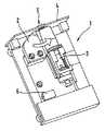
図1は、本願発明の説明のために、本願発明の実施例である携帯型の分析機器1を模式的に示すものである。前記携帯型の分析機器1は血液の分析を実施する分析器具2と切開された傷口を付与する切開傷付与器具3とを含んで構成される。切開傷付与器具3は(図示されない)ランセットと、前記ランセットの切開動作ならびに前記ランセットの引き戻し動作を完遂するための(図示されない)ランセットの発射機とで構成される。携帯型の分析機器1は、その本体容器4に開口部5を有するものであり、前記開口部5には一本の指など、身体の一部分を押し付けられると共に、そのとき前記身体部分に切開傷を付与する。 FIG. 1 schematically shows a portable
もし切開傷付与器具3が、図1に示したごとく、切開動作位置にある場合には、本体容器の開口部5に押し付けられた身体の部分に切開傷を付与することが可能である。切開傷の付与を完了すると前記切開傷付与器具3は、(図示されない)輸送器具がピボット動作、あるいは平行移動動作をすることによって収納位置に移動させられる。前記移動にともなって形成される空隙部分に収まるべく、分析器具2は本体容器の開口部5方向に移動させられ、一定の姿勢をとることになるが、この結果、前記分析器具2は付与された切開傷から流出する血液を採集できることになる。 If the
ここで説明のために示した実施例にあっては、分析器具2はベルト形状の試験片が充填されたカセットを持っている。前記試験片にはそのベルト状の長手方向に複数の区切り部分が形成されており、その区分域には種々の検査用化学成分物質が塗布されており、前記区分域の各々はそこに接触した血液に反応して、前記血液の血糖濃度に応じて肉眼で区別可能な色変化を起こす。前記分析器具2ならびに前記携帯型の分析機器1を構成するそれ以外の種々の電気部品と同様に、市販されている電池でなる内蔵電源6から電力の供給を受けている。 In the embodiment shown here for illustration, the
図1にあっては、その構成を見やすくするために、駆動器具の類、すなわち切開傷付与器具3に含まれる機能を果たすための各種機構を動作させる駆動器具類の記載はすべて省略されている。駆動器具類および切開傷付与器具3に含まれる機能を果たすための各種機構についての説明は図2および図3に基づき以下に記述する。 In FIG. 1, in order to make the configuration easy to see, descriptions of drive instruments, that is, drive instruments that operate various mechanisms for performing the functions included in the
図1におけると同様に図2において示したものは切開傷付与器具3がその切開動作位置にある状態に対応するものである。図3に示したものは前記切開傷付与器具3がその収納位置にある状態に対応するものである。前記切開傷付与器具3はこれら二つの位置を行ったりきたりする移動を繰り返すことになる。分析器具2は図1に示した本体容器の開口部5からは遠く離れた位置から移動させられ、分析実施位置に位置を取る。分析実施位置に位置することで前記分析器具2は本体容器の開口部5に押し付けられた身体部分に付与された切開傷から流れ出る液体の分析を実行することができる。前記分析器具2は実質的にそれまでは切開傷付与器具3がその切開動作位置としていた、本体容器に開口部に隣接する空間域をそれに交代して占有するものである。分析器具2と切開傷付与器具3はしたがって相互に交代する形で本体容器の開口部5に直接接する空間域に位置を取ることになる。 As in FIG. 1, what is shown in FIG. 2 corresponds to the state in which the incision
図2は切開動作位置にある状態の切開傷付与器具3を示すものである。前記図にあっては切開傷付与器具3に具備され、様々な機能を果たすための各種の機構11a、11b、11c、11dとそれらの各々を駆動するときに使用される複数の駆動器具10a、10b、10c、10dも併せて記載されている。ここで説明のために示した本願発明の実施例にあっては、切開傷付与器具3は発射用バネを緊張状態にするための第一の機能用機構11aと切開傷の深さを設定するための第二の機能用機構11c、切開傷付与器具3に搭載されるランセット・マガジンを回転させるための第三の機能用機構11bならびにランセットが切開しその後引き戻るまでのランセットの動作を起動するための第四の機能用機構11dを具備している。 FIG. 2 shows the
このような様々な機能を果たすための種々の機構を具備する切開傷付与器具3は一般的技術として知られており、たとえば独国特許出願第102004059491.0号に記載されている。またこの独国特許文献は参考までに本件出願の主題に言及されている。 The
図2に示した切開動作位置に位置する状態にある切開傷付与器具3にあっては、駆動器具の一つ10dのみが動作可能な形態で当該切開傷付与器具3と、より具体的に表現するならば、特定の一つの機能用機構11dと、係合している。これ以外の駆動器具10a、10b、10cについてはそのいずれもが当該切開傷付与器具3から、より具体的には当該機能用機構11a、11b、11cからは開放されている。図3は収納位置に位置する状態での切開傷付与器具3を図示するもので、当該駆動器具の内の三つ10a、10b、10cは動作可能に切開傷付与器具3と係合されている一方、それら以外の一つ10dは切開傷付与器具3から開放されている。 In the incision
切開傷付与器具3が駆動器具10a、10b、10c、10dと動作可能に係合することによって回転運動がこれら駆動器具10a、10b、10c、10dの内のいずれか該当するものから切開傷付与器具3に具備された機能用機構11a、11b、11c、11dの内でこの特定の駆動器具に対応した機能用機構に伝播される。このような目的を達成するために駆動器具10a、10b、10c、10dはそれぞれシャフト12a、12b、12c、12dで構成され、これら各々のシャフトは精密にすり合わせ具合を調節された摩擦接触によってそれぞれ対応する切開傷付与器具3に具備された特定の機能用機構11a、11b、11c、11dとのあいだに係合を達成する。 When the
駆動器具の一つ10dはシャフト12dを有して構成されるものであって、前記シャフト12dは本体容器4の外壁を通り抜けその外側に突出していると共にその突出した先端にはロータリー式操作ボタン13dが備わっている。前記シャフト12dは中空形状のシャフトとして形成されており、その中空部分の寸法に適合するように作製された、機能用機構の一つ11dに対応するシャフト14d(図2参照)の外側にはめ込むように押し込むことが可能であり、この押し込み動作によって、切開傷付与器具3の動作が起動される。図2に示した切開動作位置に位置する状態にある切開傷付与器具3において、これら特定の二本のシャフト12dと14dはスプライン結合で係合するする。スプライン形状の中空部ハブはこの特定のシャフト12dの先端部のみに形成されるものである。中空シャフト12dの内径は当該先端部の内の奥側でやや大きくなる様に形成され、前記スプライン形状の中空部ハブとなるものであって、この結果、図3に示すごとき切開傷付与器具3が収納位置に位置する状態においては、シャフト12dの回転運動がシャフト14dに伝達されることはない。すなわちこの状態にあっては複数の駆動器具の内の一つ特定の駆動器具10dとそれに対応する機能用機構11dとのあいだの係合は開放されている。 One of the
駆動器具の二つ10bと10cの構造は駆動器具の一つ10dの構造に対応するものである。駆動器具の二つ10bと10cはそれぞれがシャフト12bまたは12cから構成されており、本体容器4の外壁を貫通し外側に突き出ている。シャフト12bおよび12cの先端にはそれぞれロータリー式操作ボタン13bと13cが備わっており、ユーザーはこれらの操作ボタンを操作できるものである。これらのシャフト12bと12cは、各々が対応し、かつ機能用機構11bと11cにそれぞれ対応するところのシャフト14bと14cにスプライン結合によって、動作可能に係合されている。ここで切開傷付与器具3は図3に示すごとく収納位置に位置する状態にある。スプライン結合に替えて、それとは異なるタイプの精密なすり合わせ接触による接合、たとえば鋸歯状面接触による接合や多角形型表面の接触による接合をシャフト12bとシャフト14bとの係合、シャフト12cとシャフト14cとの係合に用いることも可能である。 The structure of the two
機能用に機構11aは切開傷付与器具3に備わった発射用バネを緊張状態にする機構であるがこの機構11aを動作させる駆動器具10aは電気で駆動されるモーター15で構成されている。図3に示された収納位置に位置する状態の切開傷付与器具3において、モーター15は機能用の機構11aに対応するシャフト14aと接合するシャフト12aを駆動する。この駆動器具10aは(図示しない)ボタン形状の動作部品をも含んで構成されるものであって、たとえば、ユーザーがこれを操作することで前記した電気モーターのスイッチを閉じることができる。 For function, the
シャフト12b、12c、12dとは対照的にシャフト12aは切開傷付与器具3がその収納位置からその切開動作位置まで平行移動させられる方向に対抗する方向に移動する。したがってシャフト12aの、電気モーター15があるのとは反対側の端末部分にスロット(溝状空隙)16が形成されている。シャフト14aの自由端の端面にはウェブ17が形成されており、図3に示したように切開傷付与器具3が収納位置に位置する状態に置いて、前記端面がスロット16と、タングとグルーブ方式による噛み合い係合を形成する。 In contrast to the
2 分析器具
3 切開傷付与器具
4 本体容器
5 本体容器の開口部
10a 駆動器具
10b 駆動器具
10c 駆動器具
10d 駆動器具
11a 機能用機構(機能を果たすための機構)
11b 機能用機構(機能を果たすための機構)
11c 機能用機構(機能を果たすための機構)
11d 機能用機構(機能を果たすための機構)
15 モーターDESCRIPTION OF
11b Mechanism for function (mechanism for fulfilling function)
11c Mechanism for function (mechanism for fulfilling function)
11d Mechanism for function (mechanism for fulfilling function)
15 motor
Claims (5)
Translated fromJapanese前記切開傷から採取された体液を分析する分析器具2、
ランセットと、前記ランセットが切開傷をつくるためのランセットの運動を生起させるランセット発射機からなる切開傷付与器具3、
前記ランセット発射機を含んでなる切開傷付与器具3について、切開動作位置と収納位置とのあいだで移動させる輸送器具
で構成されることを特徴とする携帯型分析機器であって、
前記切開傷付与器具3全体が切開動作位置にある状態にあっては、前記切開傷付与器具3全体は本体容器の開口部5に位置し、前記本体容器の開口部5に押し当てられる身体部分にランセットの使用によって切開傷を付与することが可能であり、
前記収納位置にある状態にあっては、前記切開傷付与器具3全体は本体容器の開口部5からは遠くはなれた場所に位置し、
前記本体容器の開口部5とのあいだにできる空隙には分析器具2が入り込み前記本体容器の開放部5に押し付けられた身体部分から流れ出る血液を採取でき、複数の駆動器具10a、10b、10c、10dが切開傷付与器具3に備わった機能を果たすための機構11a、11b、11c、11dの内それぞれが対応するものを作動するために使用され、
前記切開傷付与器具3と駆動器具10a、10b、10c、10dのそれぞれとの係合に関して、前記切開傷付与器具3が切開動作位置と収納位置のうちのいずれか一方に移動することにより、前記切開傷付与器具3が前記複数の駆動器具10a、10b、10c、10dのうちの少なくとも1つの駆動器具と係合し、切開傷付与器具3がもう一方の位置に移動することにより、前記切開傷付与器具3が前記少なくとも1つの駆動器具との係合が解除されるとともに、前記少なくとも1つの駆動器具以外の駆動器具と係合し、
前記切開傷付与器具3のみが、前記収納位置と前記切開動作位置との間を移動する
ことを特徴とする携帯型分析機器。A portable analyzer for analyzing body fluid, and a body having an opening 5 for placing a part of the body, specifically a single finger, in order to give an incision to the body part Container 4,
An analytical instrument 2 for analyzing a body fluid collected from the incision wound;
An incision imparting device 3 comprising a lancet and a lancet launcher for causing the lancet to move to make an incision.
About the incision wound imparting instrument 3 including the lancet launcher, the portable analytical instrument is constituted by a transport instrument that moves between the incision operation position and the storage position,
When theentire incision imparting device 3 is in the incision operation position, theentire incision imparting device 3 is located at the opening 5 of the main body container and is pressed against the opening 5 of the main body container. It is possible to apply an incision wound by using a lancet,
When in the storage position, theentire incision imparting device 3 is located far from the opening 5 of the main body container,
The analysis instrument 2 enters the gap formed between the opening 5 of the main body container and blood flowing out from the body part pressed against the opening 5 of the main body container can be collected, and aplurality of driving instruments 10a, 10b, 10c, 10d is used to operate the corresponding one of the mechanisms 11a, 11b, 11c, 11d for performing the function provided in the incision applying device 3,
With respect to the engagement between the incision wound imparting instrument 3 and each of the driving instruments 10a, 10b, 10c, and 10d, theincision scar imparting instrument 3 moves to one of an incision operation position and a storage position, thereby When the incision imparting device 3 isengaged with at least one of the plurality of drive devices 10a, 10b, 10c, and 10d, and the incision imparting device 3 ismoved to the other position, theincision scar is provided. The application device 3 is disengaged from the at least one drive device, and is engaged with a drive device other than the at least one drive device ;
Only the incision wound imparting instrument 3 moves between the storage position and the incision operation position.
前記駆動器具10a、10b、10c、10dのいずれかが前記切開傷付与器具3との係合が確立された状態にあるときにあっては、当該駆動器具10a、10b、10c、10dから前記切開傷付与器具3が具備する機能を果たすための機構11a、11b、11c、11dのうち、確立されている係合の相手である機構に対して力を伝達できることを特徴とする請求項1記載の携帯型分析機器。When any of the driving instruments 10a, 10b, 10c, and 10d is in a state where the engagement with the incision wound imparting instrument 3 is released, the incision is started from the driving instruments 10a, 10b, 10c, and 10d. No force can be transmitted to any of the mechanisms 11a, 11b, 11c, 11d for performing the function of the wound imparting device 3,
When any of the driving instruments 10a, 10b, 10c, and 10d is in an established state of engagement with the incision wound imparting instrument 3, the incision is performed from the driving instruments 10a, 10b, 10c, and 10d. The force can be transmitted to a mechanism that is a partner of an established engagement among the mechanisms 11a, 11b, 11c, and 11d for performing the function of the wound imparting device 3. Portable analytical instrument.
Applications Claiming Priority (2)
| Application Number | Priority Date | Filing Date | Title |
|---|---|---|---|
| EP05013559.9 | 2005-06-23 | ||
| EP05013559AEP1743577A1 (en) | 2005-06-23 | 2005-06-23 | Hand-held apparatus for the analysis of bodily fluids |
Publications (2)
| Publication Number | Publication Date |
|---|---|
| JP2007000620A JP2007000620A (en) | 2007-01-11 |
| JP4933842B2true JP4933842B2 (en) | 2012-05-16 |
Family
ID=35187123
Family Applications (1)
| Application Number | Title | Priority Date | Filing Date |
|---|---|---|---|
| JP2006162130AExpired - Fee RelatedJP4933842B2 (en) | 2005-06-23 | 2006-06-12 | Portable device for body fluid analysis |
Country Status (4)
| Country | Link |
|---|---|
| US (1) | US8382680B2 (en) |
| EP (2) | EP1743577A1 (en) |
| JP (1) | JP4933842B2 (en) |
| CA (1) | CA2550478C (en) |
Families Citing this family (80)
| Publication number | Priority date | Publication date | Assignee | Title |
|---|---|---|---|---|
| US6036924A (en)* | 1997-12-04 | 2000-03-14 | Hewlett-Packard Company | Cassette of lancet cartridges for sampling blood |
| US6391005B1 (en) | 1998-03-30 | 2002-05-21 | Agilent Technologies, Inc. | Apparatus and method for penetration with shaft having a sensor for sensing penetration depth |
| DE10057832C1 (en) | 2000-11-21 | 2002-02-21 | Hartmann Paul Ag | Blood analysis device has syringe mounted in casing, annular mounting carrying needles mounted behind test strip and being swiveled so that needle can be pushed through strip and aperture in casing to take blood sample |
| US8641644B2 (en) | 2000-11-21 | 2014-02-04 | Sanofi-Aventis Deutschland Gmbh | Blood testing apparatus having a rotatable cartridge with multiple lancing elements and testing means |
| US7041068B2 (en)* | 2001-06-12 | 2006-05-09 | Pelikan Technologies, Inc. | Sampling module device and method |
| US8337419B2 (en)* | 2002-04-19 | 2012-12-25 | Sanofi-Aventis Deutschland Gmbh | Tissue penetration device |
| US7344507B2 (en) | 2002-04-19 | 2008-03-18 | Pelikan Technologies, Inc. | Method and apparatus for lancet actuation |
| US9795747B2 (en) | 2010-06-02 | 2017-10-24 | Sanofi-Aventis Deutschland Gmbh | Methods and apparatus for lancet actuation |
| JP4272051B2 (en)* | 2001-06-12 | 2009-06-03 | ペリカン テクノロジーズ インコーポレイテッド | Blood sampling apparatus and method |
| EP1395185B1 (en) | 2001-06-12 | 2010-10-27 | Pelikan Technologies Inc. | Electric lancet actuator |
| JP4209767B2 (en) | 2001-06-12 | 2009-01-14 | ペリカン テクノロジーズ インコーポレイテッド | Self-optimized cutting instrument with adaptive means for temporary changes in skin properties |
| WO2002101359A2 (en) | 2001-06-12 | 2002-12-19 | Pelikan Technologies, Inc. | Integrated blood sampling analysis system with multi-use sampling module |
| US7981056B2 (en) | 2002-04-19 | 2011-07-19 | Pelikan Technologies, Inc. | Methods and apparatus for lancet actuation |
| US9226699B2 (en) | 2002-04-19 | 2016-01-05 | Sanofi-Aventis Deutschland Gmbh | Body fluid sampling module with a continuous compression tissue interface surface |
| AU2002344825A1 (en)* | 2001-06-12 | 2002-12-23 | Pelikan Technologies, Inc. | Method and apparatus for improving success rate of blood yield from a fingerstick |
| US7749174B2 (en) | 2001-06-12 | 2010-07-06 | Pelikan Technologies, Inc. | Method and apparatus for lancet launching device intergrated onto a blood-sampling cartridge |
| US9427532B2 (en) | 2001-06-12 | 2016-08-30 | Sanofi-Aventis Deutschland Gmbh | Tissue penetration device |
| US7344894B2 (en) | 2001-10-16 | 2008-03-18 | Agilent Technologies, Inc. | Thermal regulation of fluidic samples within a diagnostic cartridge |
| US7491178B2 (en) | 2002-04-19 | 2009-02-17 | Pelikan Technologies, Inc. | Method and apparatus for penetrating tissue |
| US7410468B2 (en)* | 2002-04-19 | 2008-08-12 | Pelikan Technologies, Inc. | Method and apparatus for penetrating tissue |
| US7717863B2 (en) | 2002-04-19 | 2010-05-18 | Pelikan Technologies, Inc. | Method and apparatus for penetrating tissue |
| US7582099B2 (en) | 2002-04-19 | 2009-09-01 | Pelikan Technologies, Inc | Method and apparatus for penetrating tissue |
| US8579831B2 (en) | 2002-04-19 | 2013-11-12 | Sanofi-Aventis Deutschland Gmbh | Method and apparatus for penetrating tissue |
| US7524293B2 (en) | 2002-04-19 | 2009-04-28 | Pelikan Technologies, Inc. | Method and apparatus for penetrating tissue |
| US7563232B2 (en)* | 2002-04-19 | 2009-07-21 | Pelikan Technologies, Inc. | Method and apparatus for penetrating tissue |
| US8267870B2 (en) | 2002-04-19 | 2012-09-18 | Sanofi-Aventis Deutschland Gmbh | Method and apparatus for body fluid sampling with hybrid actuation |
| US8221334B2 (en) | 2002-04-19 | 2012-07-17 | Sanofi-Aventis Deutschland Gmbh | Method and apparatus for penetrating tissue |
| US9248267B2 (en) | 2002-04-19 | 2016-02-02 | Sanofi-Aventis Deustchland Gmbh | Tissue penetration device |
| US7674232B2 (en) | 2002-04-19 | 2010-03-09 | Pelikan Technologies, Inc. | Method and apparatus for penetrating tissue |
| US8784335B2 (en) | 2002-04-19 | 2014-07-22 | Sanofi-Aventis Deutschland Gmbh | Body fluid sampling device with a capacitive sensor |
| US7648468B2 (en) | 2002-04-19 | 2010-01-19 | Pelikon Technologies, Inc. | Method and apparatus for penetrating tissue |
| US7481776B2 (en)* | 2002-04-19 | 2009-01-27 | Pelikan Technologies, Inc. | Method and apparatus for penetrating tissue |
| US7229458B2 (en) | 2002-04-19 | 2007-06-12 | Pelikan Technologies, Inc. | Method and apparatus for penetrating tissue |
| US7331931B2 (en)* | 2002-04-19 | 2008-02-19 | Pelikan Technologies, Inc. | Method and apparatus for penetrating tissue |
| US7297122B2 (en)* | 2002-04-19 | 2007-11-20 | Pelikan Technologies, Inc. | Method and apparatus for penetrating tissue |
| US7485128B2 (en)* | 2002-04-19 | 2009-02-03 | Pelikan Technologies, Inc. | Method and apparatus for penetrating tissue |
| US9795334B2 (en) | 2002-04-19 | 2017-10-24 | Sanofi-Aventis Deutschland Gmbh | Method and apparatus for penetrating tissue |
| US7547287B2 (en) | 2002-04-19 | 2009-06-16 | Pelikan Technologies, Inc. | Method and apparatus for penetrating tissue |
| US7708701B2 (en) | 2002-04-19 | 2010-05-04 | Pelikan Technologies, Inc. | Method and apparatus for a multi-use body fluid sampling device |
| US7371247B2 (en) | 2002-04-19 | 2008-05-13 | Pelikan Technologies, Inc | Method and apparatus for penetrating tissue |
| US7909778B2 (en) | 2002-04-19 | 2011-03-22 | Pelikan Technologies, Inc. | Method and apparatus for penetrating tissue |
| US8702624B2 (en) | 2006-09-29 | 2014-04-22 | Sanofi-Aventis Deutschland Gmbh | Analyte measurement device with a single shot actuator |
| US7291117B2 (en) | 2002-04-19 | 2007-11-06 | Pelikan Technologies, Inc. | Method and apparatus for penetrating tissue |
| US7901362B2 (en)* | 2002-04-19 | 2011-03-08 | Pelikan Technologies, Inc. | Method and apparatus for penetrating tissue |
| US9314194B2 (en) | 2002-04-19 | 2016-04-19 | Sanofi-Aventis Deutschland Gmbh | Tissue penetration device |
| US7374544B2 (en) | 2002-04-19 | 2008-05-20 | Pelikan Technologies, Inc. | Method and apparatus for penetrating tissue |
| US7232451B2 (en)* | 2002-04-19 | 2007-06-19 | Pelikan Technologies, Inc. | Method and apparatus for penetrating tissue |
| US7892183B2 (en) | 2002-04-19 | 2011-02-22 | Pelikan Technologies, Inc. | Method and apparatus for body fluid sampling and analyte sensing |
| US7976476B2 (en)* | 2002-04-19 | 2011-07-12 | Pelikan Technologies, Inc. | Device and method for variable speed lancet |
| US7141058B2 (en)* | 2002-04-19 | 2006-11-28 | Pelikan Technologies, Inc. | Method and apparatus for a body fluid sampling device using illumination |
| US8574895B2 (en) | 2002-12-30 | 2013-11-05 | Sanofi-Aventis Deutschland Gmbh | Method and apparatus using optical techniques to measure analyte levels |
| WO2004060174A2 (en)* | 2002-12-31 | 2004-07-22 | Pelikan Technologies Inc. | Method and apparatus for loading penetrating members |
| US7850621B2 (en) | 2003-06-06 | 2010-12-14 | Pelikan Technologies, Inc. | Method and apparatus for body fluid sampling and analyte sensing |
| WO2005006939A2 (en)* | 2003-06-11 | 2005-01-27 | Pelikan Technologies, Inc. | Method and apparatus for body fluid sampling and analyte sensing |
| WO2006001797A1 (en) | 2004-06-14 | 2006-01-05 | Pelikan Technologies, Inc. | Low pain penetrating |
| EP1635700B1 (en) | 2003-06-13 | 2016-03-09 | Sanofi-Aventis Deutschland GmbH | Apparatus for a point of care device |
| US8282576B2 (en) | 2003-09-29 | 2012-10-09 | Sanofi-Aventis Deutschland Gmbh | Method and apparatus for an improved sample capture device |
| EP1680014A4 (en)* | 2003-10-14 | 2009-01-21 | Pelikan Technologies Inc | METHOD AND DEVICE FOR A VARIABLE USER INTERFACE |
| US8668656B2 (en) | 2003-12-31 | 2014-03-11 | Sanofi-Aventis Deutschland Gmbh | Method and apparatus for improving fluidic flow and sample capture |
| US7822454B1 (en) | 2005-01-03 | 2010-10-26 | Pelikan Technologies, Inc. | Fluid sampling device with improved analyte detecting member configuration |
| WO2006011062A2 (en) | 2004-05-20 | 2006-02-02 | Albatros Technologies Gmbh & Co. Kg | Printable hydrogel for biosensors |
| WO2005120365A1 (en) | 2004-06-03 | 2005-12-22 | Pelikan Technologies, Inc. | Method and apparatus for a fluid sampling device |
| GB0420256D0 (en)* | 2004-09-13 | 2004-10-13 | Cassells John M | Method and apparatus for sampling and analysis of fluids |
| US8652831B2 (en) | 2004-12-30 | 2014-02-18 | Sanofi-Aventis Deutschland Gmbh | Method and apparatus for analyte measurement test time |
| US20060281187A1 (en) | 2005-06-13 | 2006-12-14 | Rosedale Medical, Inc. | Analyte detection devices and methods with hematocrit/volume correction and feedback control |
| US8801631B2 (en) | 2005-09-30 | 2014-08-12 | Intuity Medical, Inc. | Devices and methods for facilitating fluid transport |
| WO2007044599A2 (en)* | 2005-10-06 | 2007-04-19 | Hamilton Scott E | Pod connected data monitoring system |
| GB0605003D0 (en)* | 2006-03-13 | 2006-04-19 | Microsample Ltd | Method and apparatus for piercing the skin and delivery or collection of liquids |
| US20110092854A1 (en) | 2009-10-20 | 2011-04-21 | Uwe Kraemer | Instruments and system for producing a sample of a body fluid and for analysis thereof |
| BRPI0810862B8 (en) | 2007-04-30 | 2021-06-22 | Hoffmann La Roche | system for producing a body fluid sample through skin piercing |
| ES2354912T3 (en)* | 2007-05-16 | 2011-03-21 | Roche Diagnostics Gmbh | PUNCTURE SYSTEM |
| EP2265324B1 (en) | 2008-04-11 | 2015-01-28 | Sanofi-Aventis Deutschland GmbH | Integrated analyte measurement system |
| WO2009148624A1 (en) | 2008-06-06 | 2009-12-10 | Intuity Medical, Inc. | Detection meter and mode of operation |
| EP3984454A1 (en) | 2008-06-06 | 2022-04-20 | Intuity Medical, Inc. | Medical diagnostic devices and methods |
| EP2181651A1 (en) | 2008-10-29 | 2010-05-05 | Roche Diagnostics GmbH | Instrument and system for producing a sample of a body liquid and for analysis thereof |
| US9375169B2 (en) | 2009-01-30 | 2016-06-28 | Sanofi-Aventis Deutschland Gmbh | Cam drive for managing disposable penetrating member actions with a single motor and motor and control system |
| EP2506768B1 (en) | 2009-11-30 | 2016-07-06 | Intuity Medical, Inc. | Calibration material delivery devices and methods |
| US8965476B2 (en) | 2010-04-16 | 2015-02-24 | Sanofi-Aventis Deutschland Gmbh | Tissue penetration device |
| US9782114B2 (en) | 2011-08-03 | 2017-10-10 | Intuity Medical, Inc. | Devices and methods for body fluid sampling and analysis |
| EP3413957B1 (en)* | 2016-02-08 | 2020-11-18 | West Pharmaceutical Services, Inc. | Needle shield puller |
Family Cites Families (26)
| Publication number | Priority date | Publication date | Assignee | Title |
|---|---|---|---|---|
| US11759A (en)* | 1854-10-03 | palmer | ||
| US155317A (en)* | 1874-09-22 | Improvement in horse-detachers | ||
| US230216A (en)* | 1880-07-20 | Jules a | ||
| USRE32922E (en)* | 1983-01-13 | 1989-05-16 | Paul D. Levin | Blood sampling instrument |
| US4539988A (en)* | 1983-07-05 | 1985-09-10 | Packaging Corporation International | Disposable automatic lancet |
| US5035704A (en)* | 1989-03-07 | 1991-07-30 | Lambert Robert D | Blood sampling mechanism |
| DE4212315A1 (en)* | 1992-04-13 | 1993-10-14 | Boehringer Mannheim Gmbh | Blood lancet device for drawing blood for diagnostic purposes |
| US6027459A (en)* | 1996-12-06 | 2000-02-22 | Abbott Laboratories | Method and apparatus for obtaining blood for diagnostic tests |
| US5971941A (en)* | 1997-12-04 | 1999-10-26 | Hewlett-Packard Company | Integrated system and method for sampling blood and analysis |
| US6036924A (en)* | 1997-12-04 | 2000-03-14 | Hewlett-Packard Company | Cassette of lancet cartridges for sampling blood |
| CN1191786C (en)* | 1999-01-04 | 2005-03-09 | 泰尔茂株式会社 | Assembly with piercing part and body fluid collection and detection device |
| US6210420B1 (en)* | 1999-01-19 | 2001-04-03 | Agilent Technologies, Inc. | Apparatus and method for efficient blood sampling with lancet |
| JP4255556B2 (en)* | 1999-01-29 | 2009-04-15 | アークレイ株式会社 | Lancet integrated measuring device |
| US6493592B1 (en)* | 1999-12-01 | 2002-12-10 | Vertis Neuroscience, Inc. | Percutaneous electrical therapy system with electrode position maintenance |
| US6706159B2 (en)* | 2000-03-02 | 2004-03-16 | Diabetes Diagnostics | Combined lancet and electrochemical analyte-testing apparatus |
| DE10026172A1 (en)* | 2000-05-26 | 2001-11-29 | Roche Diagnostics Gmbh | Body fluid withdrawal system |
| DE10057832C1 (en)* | 2000-11-21 | 2002-02-21 | Hartmann Paul Ag | Blood analysis device has syringe mounted in casing, annular mounting carrying needles mounted behind test strip and being swiveled so that needle can be pushed through strip and aperture in casing to take blood sample |
| US6530892B1 (en)* | 2001-03-07 | 2003-03-11 | Helen V. Kelly | Automatic skin puncturing system |
| EP1328192B1 (en)* | 2001-03-29 | 2011-01-05 | Lifescan Scotland Ltd | Integrated sample testing meter |
| US6988996B2 (en)* | 2001-06-08 | 2006-01-24 | Roche Diagnostics Operatons, Inc. | Test media cassette for bodily fluid testing device |
| DE20213607U1 (en)* | 2002-02-21 | 2003-07-03 | Paul Hartmann AG, 89522 Heidenheim | Blood analyzer for the determination of an analyte |
| DE10223558A1 (en)* | 2002-05-28 | 2003-12-11 | Roche Diagnostics Gmbh | System useful in withdrawing blood for diagnostic purposes, has housing, lancet guide and lancet drive provided with drive spring, cocking device, drive rotor and outputs side coupling mechanism |
| EP1581115B1 (en)* | 2002-12-30 | 2009-10-14 | Roche Diagnostics GmbH | Blood acquisition suspension system |
| US7288102B2 (en)* | 2003-03-20 | 2007-10-30 | Facet Technologies, Llc | Lancing device with decoupled lancet |
| DE10332488A1 (en)* | 2003-07-16 | 2005-02-24 | Roche Diagnostics Gmbh | Analyzer and analysis method for body fluids |
| DE102004059491B4 (en) | 2004-12-10 | 2008-11-06 | Roche Diagnostics Gmbh | Lancet device for creating a puncture wound and lancet drive assembly |
- 2005
- 2005-06-23EPEP05013559Apatent/EP1743577A1/ennot_activeWithdrawn
- 2006
- 2006-06-10EPEP06012002Apatent/EP1736100B1/ennot_activeNot-in-force
- 2006-06-12JPJP2006162130Apatent/JP4933842B2/ennot_activeExpired - Fee Related
- 2006-06-19CACA2550478Apatent/CA2550478C/ennot_activeExpired - Fee Related
- 2006-06-21USUS11/472,020patent/US8382680B2/ennot_activeExpired - Fee Related
Also Published As
| Publication number | Publication date |
|---|---|
| CA2550478C (en) | 2012-03-27 |
| JP2007000620A (en) | 2007-01-11 |
| CA2550478A1 (en) | 2006-12-23 |
| EP1743577A1 (en) | 2007-01-17 |
| EP1736100B1 (en) | 2012-10-17 |
| US20070004990A1 (en) | 2007-01-04 |
| US8382680B2 (en) | 2013-02-26 |
| EP1736100A1 (en) | 2006-12-27 |
Similar Documents
| Publication | Publication Date | Title |
|---|---|---|
| JP4933842B2 (en) | Portable device for body fluid analysis | |
| JP5554237B2 (en) | Analysis system for automated skin puncture analysis | |
| EP2213231B1 (en) | Integrated body fluid meter and lancing device | |
| US8758382B2 (en) | Lancet magazine | |
| JP3939319B2 (en) | Blood collection system | |
| CN1981702B (en) | Analyte monitoring system with integrated lancing apparatus | |
| EP2187811B1 (en) | Lancing devices | |
| JP4472094B2 (en) | Cutting device with releasable connector | |
| US9364172B2 (en) | System for collecting samples and method for collecting a liquid sample | |
| JP6130388B2 (en) | Hand-held tissue sampler | |
| EP1415593A1 (en) | Lancing device | |
| JP6058785B2 (en) | Method and structure for assembling a lancet housing assembly of a portable medical diagnostic device | |
| JP6523263B2 (en) | Analysis device | |
| CA2575327A1 (en) | Blood collection system for collecting blood for diagnostic purposes | |
| JP5876506B2 (en) | Portable medical diagnostic device with sample transfer | |
| KR20100046260A (en) | Combination drive for a sampling system for collecting a liquid sample | |
| RU2006115423A (en) | DEVICE FOR APPLICATION OF ANASTOMOTIC RING WITH DRIVING BY DOUBLE MOVEMENT | |
| WO2009116289A1 (en) | Blood collecting puncture device and magazine used for the same | |
| KR101459398B1 (en) | Indicator for aspiration biopsy | |
| KR20140042872A (en) | Cocking and advancing mechanism for analyte testing device | |
| US20140214065A1 (en) | Blood lancet device | |
| KR20220020518A (en) | Mobile aspiration device for collection of body fluid and detection of bacteria/biomarkers | |
| HK1147667B (en) | Analysis system for automatic skin prick analysis |
Legal Events
| Date | Code | Title | Description |
|---|---|---|---|
| A977 | Report on retrieval | Free format text:JAPANESE INTERMEDIATE CODE: A971007 Effective date:20090723 | |
| A131 | Notification of reasons for refusal | Free format text:JAPANESE INTERMEDIATE CODE: A131 Effective date:20090804 | |
| RD03 | Notification of appointment of power of attorney | Free format text:JAPANESE INTERMEDIATE CODE: A7423 Effective date:20100525 | |
| A131 | Notification of reasons for refusal | Free format text:JAPANESE INTERMEDIATE CODE: A131 Effective date:20100706 | |
| A521 | Request for written amendment filed | Free format text:JAPANESE INTERMEDIATE CODE: A523 Effective date:20100929 | |
| A131 | Notification of reasons for refusal | Free format text:JAPANESE INTERMEDIATE CODE: A131 Effective date:20110816 | |
| A601 | Written request for extension of time | Free format text:JAPANESE INTERMEDIATE CODE: A601 Effective date:20111114 | |
| A602 | Written permission of extension of time | Free format text:JAPANESE INTERMEDIATE CODE: A602 Effective date:20111117 | |
| A521 | Request for written amendment filed | Free format text:JAPANESE INTERMEDIATE CODE: A523 Effective date:20120105 | |
| TRDD | Decision of grant or rejection written | ||
| A01 | Written decision to grant a patent or to grant a registration (utility model) | Free format text:JAPANESE INTERMEDIATE CODE: A01 Effective date:20120207 | |
| A01 | Written decision to grant a patent or to grant a registration (utility model) | Free format text:JAPANESE INTERMEDIATE CODE: A01 | |
| A61 | First payment of annual fees (during grant procedure) | Free format text:JAPANESE INTERMEDIATE CODE: A61 Effective date:20120217 | |
| R150 | Certificate of patent or registration of utility model | Ref document number:4933842 Country of ref document:JP Free format text:JAPANESE INTERMEDIATE CODE: R150 Free format text:JAPANESE INTERMEDIATE CODE: R150 | |
| FPAY | Renewal fee payment (event date is renewal date of database) | Free format text:PAYMENT UNTIL: 20150224 Year of fee payment:3 | |
| R250 | Receipt of annual fees | Free format text:JAPANESE INTERMEDIATE CODE: R250 | |
| R250 | Receipt of annual fees | Free format text:JAPANESE INTERMEDIATE CODE: R250 | |
| R250 | Receipt of annual fees | Free format text:JAPANESE INTERMEDIATE CODE: R250 | |
| R250 | Receipt of annual fees | Free format text:JAPANESE INTERMEDIATE CODE: R250 | |
| R250 | Receipt of annual fees | Free format text:JAPANESE INTERMEDIATE CODE: R250 | |
| R250 | Receipt of annual fees | Free format text:JAPANESE INTERMEDIATE CODE: R250 | |
| R250 | Receipt of annual fees | Free format text:JAPANESE INTERMEDIATE CODE: R250 | |
| LAPS | Cancellation because of no payment of annual fees |