JP4933069B2 - Vehicle indicator instrument - Google Patents
Vehicle indicator instrumentDownload PDFInfo
- Publication number
- JP4933069B2 JP4933069B2JP2005248122AJP2005248122AJP4933069B2JP 4933069 B2JP4933069 B2JP 4933069B2JP 2005248122 AJP2005248122 AJP 2005248122AJP 2005248122 AJP2005248122 AJP 2005248122AJP 4933069 B2JP4933069 B2JP 4933069B2
- Authority
- JP
- Japan
- Prior art keywords
- light
- pointer
- dial
- speedometer
- hole
- Prior art date
- Legal status (The legal status is an assumption and is not a legal conclusion. Google has not performed a legal analysis and makes no representation as to the accuracy of the status listed.)
- Expired - Fee Related
Links
Images


Classifications
- B—PERFORMING OPERATIONS; TRANSPORTING
- B60—VEHICLES IN GENERAL
- B60K—ARRANGEMENT OR MOUNTING OF PROPULSION UNITS OR OF TRANSMISSIONS IN VEHICLES; ARRANGEMENT OR MOUNTING OF PLURAL DIVERSE PRIME-MOVERS IN VEHICLES; AUXILIARY DRIVES FOR VEHICLES; INSTRUMENTATION OR DASHBOARDS FOR VEHICLES; ARRANGEMENTS IN CONNECTION WITH COOLING, AIR INTAKE, GAS EXHAUST OR FUEL SUPPLY OF PROPULSION UNITS IN VEHICLES
- B60K2360/00—Indexing scheme associated with groups B60K35/00 or B60K37/00 relating to details of instruments or dashboards
- B60K2360/60—Structural details of dashboards or instruments
- B60K2360/68—Features of instruments
- B60K2360/698—Pointers of combined instruments
- B60K2360/6992—Light conducting pointers
Landscapes
- Details Of Measuring Devices (AREA)
- Instrument Panels (AREA)
Description
Translated fromJapanese本発明は、車両用指針計器に関するもので、たとえば自動車に用いて好適である。 The present invention relates to a pointer instrument for a vehicle, and is suitable for use in, for example, an automobile.
従来の車両用指針計器としては、たとえば車両用指針計器の見映えを向上させるために、文字板の表面に枠状部材としてのリング部材を装着し、指針に光を照射するための文字板の開口部から漏れた光によりこのリング部材の内壁面を照明している。(特許文献1参照)。
しかしながら、上述した従来の車両用指針計器においては、文字板の開口部から漏れた光が直接リング部材を照射する構成としているため、リング部材の内壁面の照度が低いという問題があった。 However, the conventional vehicle pointer instrument described above has a problem in that the illuminance on the inner wall surface of the ring member is low because the light leaking from the opening of the dial plate directly irradiates the ring member.
本発明は、上記の点に鑑みて成されたものであり、その目的は、リング部材を高照度で視認させることが可能な車両用指針計器を提供することである。 The present invention has been made in view of the above points, and an object of the present invention is to provide a vehicular pointer instrument capable of visually recognizing a ring member with high illuminance.
本発明は、上記目的を達成する為に以下の技術的手段を採用する。 The present invention employs the following technical means to achieve the above object.
本発明の請求項1に記載の車両用指針計器は、表示意匠が形成された文字板と、文字板の前面側に配置される透明カバーと、文字板の背面側に配置されて回転軸を回転させるムーブメントと、文字板に設けられた回転軸が挿通される貫通孔と、回転軸に固定されて文字板の前面側を回動するように配置された指針と、文字板の背面側に貫通孔を通して指針に光を入射可能に配置された光源とを備えた車両用指針計器であって、文字板の前面側且つ表示意匠の外周側に配置された枠体と、指針の前面側且つ透明カバーの背面側において、貫通孔を覆うように指針及び透明カバーとは分離して配置され且つ枠体と一体的に形成され、貫通孔を通過した光源からの光を枠体に照射する遮光部材とを備えることを特徴とするものである。The pointer instrument for a vehicle according to
このような構成によれば、貫通孔を通過した光源からの光の一部は直接枠体を照射する。さらに、貫通孔を通過した光源からの光の一部は遮光部材の裏面で反射した後に枠体を照射する。すなわち、枠体は、貫通孔を通過した光源からの光と、一旦遮光部材で反射した光源からの光との両方の光により照射される。 According to such a configuration, part of the light from the light source that has passed through the through hole directly irradiates the frame. Further, a part of the light from the light source that has passed through the through hole is reflected on the back surface of the light shielding member, and then irradiates the frame. That is, the frame body is irradiated with both the light from the light source that has passed through the through hole and the light from the light source that has been once reflected by the light shielding member.
これにより、従来の車両用指針計器に対して枠体を照射する光量を増加させることができるので、枠体の照度を高めることができる。以上により、枠体を高照度で視認させることが可能な車両用指針計器を提供することができる。Thereby, since the light quantity which irradiates a frame with respect to the conventional pointer instrument for vehicles can be increased, the illumination intensity of a frame can be raised.As described above, it is possible to provide a vehicular pointer instrument capable of visually recognizing the frame body with high illuminance.
加えて、枠体および遮光部材が一体的に形成されるので、遮光部材と枠体との位置関係は高精度に維持される。故に、枠体の照度は、均一且つ高いものになる。さらに、車両用指針計器の部品点数、組付け工数を低減することができる。In addition, since the frame body and the light shielding member are integrally formed, the positional relationship between the light shielding member and the frame body is maintained with high accuracy. Therefore, the illuminance of the frame is uniform and high. Furthermore, it is possible to reduce the number of parts and assembly man-hours of the vehicle pointer instrument.
本発明の請求項2に記載の車両用指針計器は、枠体は外側に向かうにしたがって徐々に開口する断面凸状に形成されたことを特徴とするものである。 The pointer instrument for a vehicle according to
このような構成によれば、光源からの光の枠体における反射光はある程度の角度範囲を持って文字板の前方、つまり視認者側へ向かう。したがって、視認者の姿勢が変化したり、あるいは、視認者の体格が異なる場合でも、枠体の明るさをほぼ同じに視認させることができる。 According to such a configuration, the reflected light from the light source on the frame of the light travels forward of the dial, that is, toward the viewer side with a certain angle range. Therefore, even when the viewer's posture changes or the viewer's physique is different, the brightness of the frame can be viewed almost the same.
以下、本発明による車両用指針計器を、自動車の車室内に設置されたスピードメータ1に適用した場合を例に図面に基づいて説明する。 Hereinafter, an example in which a vehicular pointer instrument according to the present invention is applied to a
(第1実施形態)
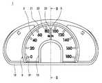
図1は、本発明の第1実施形態によるスピードメータ1の正面図である。なお、図1において、上方が自動車の上方であり、左右方向が自動車の幅方向となっている。(First embodiment)
FIG. 1 is a front view of a
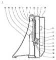
図2は、本発明の第1実施形態によるスピードメータ1の断面図であり、図1中のII−II線断面図である。なお、図2において、左方が運転席であり、スピードメータ1は、図2において、左側から視認される。 FIG. 2 is a cross-sectional view of the
図3は、本発明の第1実施形態によるスピードメータ1の枠体である装飾リング9、および遮光部材であるセンターカバー10の正面図である。 FIG. 3 is a front view of the
図4は、本発明の第1実施形態によるスピードメータ1の電気回路構成を説明する模式図である。 FIG. 4 is a schematic diagram for explaining an electric circuit configuration of the
スピードメータ1は、当該自動車の車室内の運転席前方に運転者が視認可能に設けられ、当該自動車の走行速度を指針により指示するものである。 The
以下に、本発明の第1実施形態によるスピードメータ1の構成について説明する。 Below, the structure of the
文字板2は、透光性材料、たとえば無色透明のポリカーボネート樹脂あるいはアクリル樹脂等の薄板から形成されている。文字板2は、表示意匠としての目盛21、数字22および文字23を備えている。目盛21および数字22は、後述する指針5とともに当該自動車の走行速度を指示するためのものである。また、文字23は、表示される走行速度の単位を表している。目盛21、数字22および文字23は、文字板2の表面25に、目盛21、数字22および文字23を除いて遮光性皮膜を印刷等により施して形成されている。すなわち、目盛21、数字22および文字23のみが透光性となり、それらの周囲は遮光性となっている。これにより、目盛21、数字22および文字23は、文字板2の裏側(図2の右側)に配置された後述する発光ダイオード4からの光により透過照明されて発光表示される。 The
また、文字板2には、図2に示すように、後述する駆動装置としてのムーブメント6のシャフト61と指針5のスリーブ5aとで構成される回転軸を挿通させるための貫通孔24が設けられている。なお、指針5のスリーブ5aを廃止してシャフト61を文字板2の貫通孔24から延出させて指針5に接続するようにしてもよい。 Further, as shown in FIG. 2, the
なお、本発明の第1実施形態によるスピードメータ1においては、目盛21、数字22および文字23に透光性白色塗装を施し、且つそれらの周囲に遮光性黒色塗装を施している。しかしながら、上述のような組み合わせに限定する必要はなく、目盛21、数字22および文字23を無色透明のままとしてもよい。この場合は、目盛21、数字22および文字23は発光ダイオード4の発光色で発光表示されることになる。 In the
文字板2の裏側(図2において右側)には、光源である発光ダイオード4からの光を文字板2および指針5へ導くための導く導光体3が配置されている。導光体3は、透光性材料、たとえば無色透明のポリカーボネート樹脂あるいはアクリル樹脂等から形成されている。導光体3は、図2に示すように、発光ダイオード4が発する光を文字板2の目盛21、数字22および文字23へ導くための文字板導光部31と、発光ダイオード4が発する光を指針5へ導くための指針導光部32とから構成されている。文字板導光部31は、図2に示すように、概略円板状に形成されるとともに、指針導光部32は、図2に示すように、円筒状に形成されている。 On the back side of the dial plate 2 (right side in FIG. 2), a
文字板2の背後、つまり導光体3の背後には、図2に示すように、光源である発光ダイオード4が指針5、つまり導光体3に光を入射可能に配置されている。発光ダイオード4は、たとえば白色で発光する白色発光ダイオードが用いられている。全ての目盛21、数字22および文字23を均一な明るさで発光表示させ、且つ指針をその回転角度域全域において均一な明るさで発光表示させるために、発光ダイオード4は、複数個、たとえば3個設けられている。 As shown in FIG. 2, a
指針5は、透光性材料、たとえば無色透明のポリカーボネート樹脂あるいはアクリル樹脂等から形成され、図2に示すように、文字板2の運転席側(図2において左側)に沿って配置されている。指針5は、文字板2の裏側(図2において右側)に配置される後述する駆動装置であるムーブメント6の回転軸であるシャフト61に固定されている。これにより、ムーブメント6が駆動されてシャフト61が回動すると、指針5はシャフト61と一体的に回動する。指針5の裏面51は、印刷あるいはホットスタンプ等により赤色に着色されている。これにより、指針5は、上述した発光ダイオード4からの光により照明されて赤色で発光表示される。すなわち、指針5に入射した発光ダイオード4から発せられた光は、指針5の反射面52で指針5の先端方向に向けて反射され、さらにこの反射光が裏面51で運転者の視認方向に反射される。すなわち、本発明の第1実施形態によるスピードメータ1においては、発光ダイオード4として白色発光ダイオードを用いることにより、指針5を、指針5の裏面51に施した着色層の色で発光表示している。この場合、指針5の裏面51に施した着色層の色を赤色に限定する必要はなく、他の色、たとえば、橙色、緑色等に着色してもよい。一方、指針5の裏面51に白色着色層を設けるとともに、発光ダイオード4として発光色が白以外の色の発光ダイオードを用いてもよい。この場合は、指針5は、発光ダイオード4の発光色により発光表示される。なお、指針5を、無色透明ではなく、着色透明の樹脂材料から形成して、その着色された色で指針5の発光表示してもよい。 The
指針5を回動させるための駆動力を発生するムーブメント6は、たとえば交差コイル式アクチュエータあるいはステッピングモータ等が用いられている。ムーブメント6は、外部から電圧を印加されるとトルクを発生し回転軸であるシャフト61を回動させる。これにより、シャフト61先端に固定された指針5が、文字板2の表面25に沿って回動する。 For example, a cross coil actuator or a stepping motor is used as the
上述した、発光ダイオード4、ムーブメント6は、文字板2の裏側(図2の右側)に配置されているプリント基板7上に実装されている。プリント基板7は、たとえばガラスエポキシ基板等から形成され、スピードメータ1の電気回路部を形成している。プリント基板7には、図2に示すように、発光ダイオード4の点灯・消灯制御および指針5を回動させるためのムーブメント6の駆動制御を行うためのコントローラ8が実装されている。コントローラ8は、たとえばマイクロコンピュータ等から構成されている。 The
文字板2の前面側(図2において左側)には、図2に示すように、見返し板12が配置されている。見返し板2は、本発明の第1実施形態によるスピードメータ1においては樹脂材料から形成されている。見返し板2は、図1に示すように、文字板2上の表示意匠である目盛21、数字22および文字23を視認可能としつつ概略枠状に形成され、スピードメータ1の輪郭形状を整えている。 On the front side of the dial 2 (left side in FIG. 2), a facing
文字板2の前面側(図2において左側)には、図2に示すように、枠体である装飾リング9が装着されている。装飾リング9は、図2に示すように、表示意匠の外周側、つまり放射上且つ円弧上に配置された目盛21の外周側に位置されている。言い換えると、装飾リング9は、指針5と同軸上に配置されている。装飾リング9は、本発明の第1実施形態によるスピードメータ1においては樹脂材料から形成されている。装飾リング9の断面形状は、図2に示すように、外側、つまり運転席側である図2の左側に向かうにしたがって徐々に開口する凸状に形成されている。これにより、装飾リング9の内周側には略円錐面状の斜面91が形成されている。装飾リング9は、見返し板12に固定されている。 On the front side of the dial 2 (left side in FIG. 2), as shown in FIG. As shown in FIG. 2, the
指針5の前面側(図2において左側)には、文字板2の貫通孔24を覆うように且つ指針5とは分離して、つまり指針5とは隙間を保って指針5の回動を妨げないようにして遮光部材であるセンターカバー10が配置されている。センターカバー10は、樹脂材料から形成されている。センターカバー10は、本発明の第1実施形態によるスピードメータ1においては、装飾リング9と一体的に形成されている。すなわち、センターカバー10および装飾リング9は、図3に示すように、1個の部品として形成されている。したがって、センターカバー10も装飾リング9と同様に見返し板12に固定されている。センターカバー10の輪郭、つまり運転者の視認方向から見た時の輪郭は、図1に示すように、その一部が円弧状に形成され、この円弧は文字板2の貫通孔24と同軸上且つ装飾リング9と同軸上である。センターカバー10は、発光ダイオード4からの光が文字板2の貫通孔24を経て直接運転者の眼に入射することを阻止している。さらに、センターカバー10は、貫通孔24を経てセンターカバー10に入射した光を拡散反射させて装飾リング9を照明する機能を果たしている。 On the front side of the pointer 5 (left side in FIG. 2), it covers the through
以上説明した、文字板2、ムーブメント6、プリント基板7および見返し板12はケース11内に収容・固定されている。見返し板12の先端部には、図2に示すように、透明カバー13が取り付けられている。透明カバー13は、無色透明のポリカーボネート樹脂あるいはアクリル樹脂等からの薄板状に形成されている。一方、ケース11の背後(図2において右側)には、ロアケース14が取り付けられている。ロアケース14は、樹脂材料から形成されている。 The
次に、以上説明した、本発明の第1実施形態によるスピードメータ1の電気回路構成について、図4に基づいて説明する。 Next, the electric circuit configuration of the
図4に示すように、コントローラ8には、バッテリ17から電力が常時供給されている。コントローラ8には、イグニッションスイッチ16が、その操作状態(ONまたはOFF)を検出可能に接続されている。コントローラ8には、図4に示すように、発光ダイオード4およびムーブメント6が接続されている。 As shown in FIG. 4, electric power is constantly supplied from the
運転者の操作によりイグニッションスイッチ16がONされると、コントローラ8は、走行速度指示制御を開始する。すなわち、発光ダイオード4を点灯させるとともに、速度センサ15からの検出信号に基づいて当該自動車の走行速度を算出し、算出した走行速度を指針5が文字板2上に指示するようムーブメント6を駆動する。 When the
イグニッションスイッチ16がOFFされると、コントローラ8は、各発光ダイオード4を消灯させるとともに、指針5が文字板2上において走行速度0km/hを指示するようムーブメント6を駆動する。あるいは、ムーブメント6への通電を停止する。ムーブメント6への通電を停止した場合は、ムーブメント6のシャフト61は、リターンスプリング(図示せず)の弾性力等により指針5が走行速度0km/hを指示する位置まで回転する。 When the
次に、本発明の第1実施形態によるスピードメータ1の特徴である、センターカバー10の、装飾リング9の照明におよぼす作用効果について説明する。 Next, the effect of the
先ず、従来の車両用指針計器においては、文字板の開口部から漏れた光が直接リング部材を照射する構成としているため、リング部材を照射する光量が少なく、リング部材の照度が低いという問題があった。 First, in the conventional pointer instrument for a vehicle, since the light leaking from the opening of the dial plate directly irradiates the ring member, there is a problem that the amount of light irradiating the ring member is small and the illuminance of the ring member is low. there were.
これに対して、本発明の第1実施形態によるスピードメータ1では、文字板2の貫通孔24を覆うように、センターカバー10を設けている。このため、貫通孔24を経てセンターカバー10に入射した発光ダイオード4からの光はセンターカバー10の裏面10aで拡散反射され、この反射光の一部は装飾リング9の斜面91に入射し、さらに運転者の視認方向へ反射する。もちろん、文字板2の貫通孔24を通過した発光ダイオード4からの光の一部は、直接装飾リング9の斜面91に入射する。 On the other hand, in the
これにより、本発明の第1実施形態によるスピードメータ1では、貫通孔24からの漏光により照明される装飾リング9の照度を高めることができる。 Thereby, in the
また、貫通孔24を経てセンターカバー10に入射した光はセンターカバー10の裏面10aで拡散反射されるため、センターカバー10の外周へ出て行く光の光量はセンターカバー10の周方向においてほぼ均一となる。したがって、装飾リング9に入射する光量も装飾リング9の全周に亘って均一となり、これにより、装飾リング9はその全周に亘って、均一な明るさで照明される。 In addition, since the light incident on the
なお、発光ダイオード4から出射し貫通孔24を通過した光の大部分は、図2から明らかなように、指針5のスリーブ5a近傍を透過してセンターカバー10に入射する。したがって、指針5が着色透明の樹脂材料から形成されている場合は、センターカバー10の外周から装飾リング9に向けて照射される光は、指針5の着色の色光となる。すなわち、指針5を着色透明の樹脂材料から形成することにより、装飾リング9の照明色を必要に応じて変えることができる。 Note that most of the light emitted from the
以上により、本発明の第1実施形態によるスピードメータ1では、従来の車両用指針計器に比較して、装飾リング9を、より明るく且つその全周に亘り均一な照度で視認させることができる。 As described above, in the
したがって、装飾リング9を全周に亘り均一な明るさ且つ高照度で視認させることが可能なスピードメータ1を提供することができる。 Therefore, it is possible to provide the
なお、以上説明した、本発明の第1実施形態によるスピードメータ1においては、装飾リング9とセンターカバー10を一つの部品として一体的に形成しているが、これらを、見返し板12と一体的に形成してもよい。つまり、装飾リング9、センターカバー10および見返し板12の3部品を1個の部品として形成してもよい。あるいは、装飾リング9およびセンターカバー10のどちらかを見返し板12と一体的に形成し、他方は別部品とする構成としてもよい。 In the
また、以上説明した、本発明の第1実施形態によるスピードメータ1においては、文字板2において、目盛21、数字22および文字23を透光性として透過照明により発光表示し、それら以外の部分、つまり背景部を遮光性としているが。しかし、この構成に限る必要は無く、たとえば、文字板2の背景部を透光性として面状に発光させ且つ目盛21、数字22および文字23を遮光性として、目盛21、数字22および文字23が明るい背景の中に黒く視認される構成としてもよい。ところで、貫通孔24を経てセンターカバー10の裏面10aに入射しそこで拡散反射した反射光の一部は文字板2の表面を照射する。そこで、文字板2の背景部を面発光させる構成とすれば、スピードメータ1の文字板2の見栄えにおよぼす反射光の影響を低減することができる。 Moreover, in the
また、以上説明した、本発明の第1実施形態および第2実施形態によるスピードメータ1においては、光源として発光ダイオード4を用いているが、他の種類の光源、たとえば電球、放電等あるいはELパネル等に置き換えてもよい。 In the
また、以上説明した実施形態は、本発明による車両用指針計器を、自動車のスピードメータ1に適用した場合を例に説明しているが、適用対象をスピードメータ1に限る必要は無く、他の種類の車両用指針計器、たとえば、当該自動車のエンジン回転速度を指示するエンジンタコメータ、エンジン冷却水温度を指示する水温計等に適用してもよい。また、複数個の本発明による車両用指針計器を一まとめに備えるいわゆるコンビネーションメータに適用してもよい。 Moreover, although embodiment described above has demonstrated as an example the case where the pointer instrument for vehicles by this invention is applied to the
1 スピードメータ(車両用指針計器)
2 文字板
21 目盛(表示意匠)
22 数字(表示意匠)
23 文字(表示意匠)
24 貫通孔
3 導光体
31 文字板導光部
32 指針導光部
4 発光ダイオード(光源)
5 指針
51 裏面
52 反射面
6 ムーブメント
61 シャフト(回転軸)
7 プリント基板
8 コントローラ
9 装飾リング(枠体)
91 斜面
10 センターカバー(遮光部材)
11 ケース
12 見返し板
13 透明カバー
14 ロアケース
15 速度センサ
16 イグニッションスイッチ
17 バッテリ1 Speedometer (Vehicle pointer instrument)
2
22 Numbers (display design)
23 characters (display design)
24 Through-
5
7 Printed
91
11
Claims (2)
Translated fromJapanese前記文字板の前面側に配置される透明カバーと、
前記文字板の背面側に配置されて回転軸を回転させるムーブメントと、
前記文字板に設けられて前記回転軸が挿通される貫通孔と、
前記回転軸に接続されて前記文字板の前面側を回動するように配置された指針と、
前記文字板の背面側に前記貫通孔を通して前記指針に光を入射可能に配置された光源とを備えた車両用指針計器であって、
前記文字板の前面側且つ前記表示意匠の外周側に配置された枠体と、
前記指針の前面側且つ前記透明カバーの背面側において、前記貫通孔を覆うように前記指針及び前記透明カバーとは分離して配置され且つ前記枠体と一体的に形成され、前記貫通孔を通過した前記光源からの光を前記枠体に照射する遮光部材とを備えることを特徴とする車両用指針計器。A dial on which a display design is formed;
A transparent cover disposed on the front side of the dial,
A movement that is arranged on the back side of the dial and rotates a rotating shaft;
A through hole provided in the dial and through which the rotating shaft is inserted;
A pointer connected to the rotating shaft and arranged to rotate the front side of the dial;
A pointer instrument for a vehicle comprising a light source disposed on the back side of the dial so that light can be incident on the pointer through the through hole;
A frame disposed on the front side of the dial and on the outer peripheral side of the display design;
On the front side of the pointer and on the back side of the transparent cover, the pointer and the transparent cover are arranged separately from each other so as to cover thethrough hole, and are formed integrally with the frame and pass through the through hole. And a light shielding memberthat irradiates the frame with light from the light source .
Priority Applications (1)
| Application Number | Priority Date | Filing Date | Title |
|---|---|---|---|
| JP2005248122AJP4933069B2 (en) | 2005-08-29 | 2005-08-29 | Vehicle indicator instrument |
Applications Claiming Priority (1)
| Application Number | Priority Date | Filing Date | Title |
|---|---|---|---|
| JP2005248122AJP4933069B2 (en) | 2005-08-29 | 2005-08-29 | Vehicle indicator instrument |
Publications (2)
| Publication Number | Publication Date |
|---|---|
| JP2007064682A JP2007064682A (en) | 2007-03-15 |
| JP4933069B2true JP4933069B2 (en) | 2012-05-16 |
Family
ID=37927068
Family Applications (1)
| Application Number | Title | Priority Date | Filing Date |
|---|---|---|---|
| JP2005248122AExpired - Fee RelatedJP4933069B2 (en) | 2005-08-29 | 2005-08-29 | Vehicle indicator instrument |
Country Status (1)
| Country | Link |
|---|---|
| JP (1) | JP4933069B2 (en) |
Families Citing this family (3)
| Publication number | Priority date | Publication date | Assignee | Title |
|---|---|---|---|---|
| JP4329061B2 (en)* | 2003-04-25 | 2009-09-09 | 日本精機株式会社 | Instrument device |
| JP5348087B2 (en)* | 2010-07-26 | 2013-11-20 | 株式会社デンソー | Vehicle instrument |
| DE102015225066A1 (en)* | 2015-12-14 | 2017-06-14 | Continental Automotive Gmbh | Display with a lighted trim |
Family Cites Families (4)
| Publication number | Priority date | Publication date | Assignee | Title |
|---|---|---|---|---|
| JP2001249033A (en)* | 2000-03-02 | 2001-09-14 | Denso Corp | Measuring instrument |
| JP3567865B2 (en)* | 2000-07-21 | 2004-09-22 | 株式会社デンソー | Display panel and method of manufacturing display panel |
| JP4329061B2 (en)* | 2003-04-25 | 2009-09-09 | 日本精機株式会社 | Instrument device |
| JP2005134308A (en)* | 2003-10-31 | 2005-05-26 | Nippon Seiki Co Ltd | Indicating instrument |
- 2005
- 2005-08-29JPJP2005248122Apatent/JP4933069B2/ennot_activeExpired - Fee Related
Also Published As
| Publication number | Publication date |
|---|---|
| JP2007064682A (en) | 2007-03-15 |
Similar Documents
| Publication | Publication Date | Title |
|---|---|---|
| JP5182216B2 (en) | Vehicle display device | |
| JP2006003341A (en) | Display | |
| JP4437550B2 (en) | Vehicle indicator instrument | |
| JP4977403B2 (en) | Vehicle display device | |
| JP5045403B2 (en) | Pointer instrument | |
| JP4984847B2 (en) | Display device | |
| JP4933069B2 (en) | Vehicle indicator instrument | |
| JP4175308B2 (en) | Vehicle indicator instrument | |
| JP4228977B2 (en) | Display device | |
| JP2007085858A (en) | Vehicle indicator instrument | |
| JP4858228B2 (en) | Pointer instrument | |
| JP3855954B2 (en) | Vehicle indicator instrument | |
| JP2007309837A (en) | Display | |
| JP2006118892A (en) | Pointer instrument | |
| JP4075843B2 (en) | Vehicle indicator instrument | |
| JP4600234B2 (en) | Vehicle instrument | |
| JP2005061924A (en) | Pointer instrument for car | |
| JP3812540B2 (en) | Vehicle instrument | |
| JP2005345287A (en) | Pointer meter | |
| JP4655900B2 (en) | Vehicle instrument | |
| JP4175321B2 (en) | Pointer instrument | |
| JP4259480B2 (en) | Vehicle instrument | |
| JP4652787B2 (en) | Display device | |
| JP2005326183A (en) | Display device | |
| JP2003202247A (en) | Pointer type measuring instrument |
Legal Events
| Date | Code | Title | Description |
|---|---|---|---|
| A621 | Written request for application examination | Free format text:JAPANESE INTERMEDIATE CODE: A621 Effective date:20070904 | |
| A977 | Report on retrieval | Free format text:JAPANESE INTERMEDIATE CODE: A971007 Effective date:20100127 | |
| A131 | Notification of reasons for refusal | Free format text:JAPANESE INTERMEDIATE CODE: A131 Effective date:20100316 | |
| A521 | Request for written amendment filed | Free format text:JAPANESE INTERMEDIATE CODE: A523 Effective date:20100510 | |
| A02 | Decision of refusal | Free format text:JAPANESE INTERMEDIATE CODE: A02 Effective date:20100615 | |
| A521 | Request for written amendment filed | Free format text:JAPANESE INTERMEDIATE CODE: A523 Effective date:20100823 | |
| A911 | Transfer to examiner for re-examination before appeal (zenchi) | Free format text:JAPANESE INTERMEDIATE CODE: A911 Effective date:20100924 | |
| A912 | Re-examination (zenchi) completed and case transferred to appeal board | Free format text:JAPANESE INTERMEDIATE CODE: A912 Effective date:20101112 | |
| A521 | Request for written amendment filed | Free format text:JAPANESE INTERMEDIATE CODE: A523 Effective date:20120116 | |
| A01 | Written decision to grant a patent or to grant a registration (utility model) | Free format text:JAPANESE INTERMEDIATE CODE: A01 | |
| A61 | First payment of annual fees (during grant procedure) | Free format text:JAPANESE INTERMEDIATE CODE: A61 Effective date:20120216 | |
| R150 | Certificate of patent or registration of utility model | Ref document number:4933069 Country of ref document:JP Free format text:JAPANESE INTERMEDIATE CODE: R150 Free format text:JAPANESE INTERMEDIATE CODE: R150 | |
| FPAY | Renewal fee payment (event date is renewal date of database) | Free format text:PAYMENT UNTIL: 20150224 Year of fee payment:3 | |
| R250 | Receipt of annual fees | Free format text:JAPANESE INTERMEDIATE CODE: R250 | |
| R250 | Receipt of annual fees | Free format text:JAPANESE INTERMEDIATE CODE: R250 | |
| R250 | Receipt of annual fees | Free format text:JAPANESE INTERMEDIATE CODE: R250 | |
| R250 | Receipt of annual fees | Free format text:JAPANESE INTERMEDIATE CODE: R250 | |
| R250 | Receipt of annual fees | Free format text:JAPANESE INTERMEDIATE CODE: R250 | |
| R250 | Receipt of annual fees | Free format text:JAPANESE INTERMEDIATE CODE: R250 | |
| R250 | Receipt of annual fees | Free format text:JAPANESE INTERMEDIATE CODE: R250 | |
| LAPS | Cancellation because of no payment of annual fees |