JP4932266B2 - Endoscope system - Google Patents
Endoscope systemDownload PDFInfo
- Publication number
- JP4932266B2 JP4932266B2JP2006021961AJP2006021961AJP4932266B2JP 4932266 B2JP4932266 B2JP 4932266B2JP 2006021961 AJP2006021961 AJP 2006021961AJP 2006021961 AJP2006021961 AJP 2006021961AJP 4932266 B2JP4932266 B2JP 4932266B2
- Authority
- JP
- Japan
- Prior art keywords
- tissue
- endoscope
- attachment
- conduit
- suction
- Prior art date
- Legal status (The legal status is an assumption and is not a legal conclusion. Google has not performed a legal analysis and makes no representation as to the accuracy of the status listed.)
- Expired - Fee Related
Links
Images


Classifications
- A—HUMAN NECESSITIES
- A61—MEDICAL OR VETERINARY SCIENCE; HYGIENE
- A61B—DIAGNOSIS; SURGERY; IDENTIFICATION
- A61B1/00—Instruments for performing medical examinations of the interior of cavities or tubes of the body by visual or photographical inspection, e.g. endoscopes; Illuminating arrangements therefor
- A61B1/012—Instruments for performing medical examinations of the interior of cavities or tubes of the body by visual or photographical inspection, e.g. endoscopes; Illuminating arrangements therefor characterised by internal passages or accessories therefor
- A61B1/015—Control of fluid supply or evacuation
- A—HUMAN NECESSITIES
- A61—MEDICAL OR VETERINARY SCIENCE; HYGIENE
- A61B—DIAGNOSIS; SURGERY; IDENTIFICATION
- A61B1/00—Instruments for performing medical examinations of the interior of cavities or tubes of the body by visual or photographical inspection, e.g. endoscopes; Illuminating arrangements therefor
- A61B1/00064—Constructional details of the endoscope body
- A61B1/00066—Proximal part of endoscope body, e.g. handles
- A61B1/00068—Valve switch arrangements
- A—HUMAN NECESSITIES
- A61—MEDICAL OR VETERINARY SCIENCE; HYGIENE
- A61B—DIAGNOSIS; SURGERY; IDENTIFICATION
- A61B1/00—Instruments for performing medical examinations of the interior of cavities or tubes of the body by visual or photographical inspection, e.g. endoscopes; Illuminating arrangements therefor
- A61B1/00131—Accessories for endoscopes
- A61B1/00137—End pieces at either end of the endoscope, e.g. caps, seals or forceps plugs
- A—HUMAN NECESSITIES
- A61—MEDICAL OR VETERINARY SCIENCE; HYGIENE
- A61B—DIAGNOSIS; SURGERY; IDENTIFICATION
- A61B1/00—Instruments for performing medical examinations of the interior of cavities or tubes of the body by visual or photographical inspection, e.g. endoscopes; Illuminating arrangements therefor
- A61B1/012—Instruments for performing medical examinations of the interior of cavities or tubes of the body by visual or photographical inspection, e.g. endoscopes; Illuminating arrangements therefor characterised by internal passages or accessories therefor
- A61B1/018—Instruments for performing medical examinations of the interior of cavities or tubes of the body by visual or photographical inspection, e.g. endoscopes; Illuminating arrangements therefor characterised by internal passages or accessories therefor for receiving instruments
- A—HUMAN NECESSITIES
- A61—MEDICAL OR VETERINARY SCIENCE; HYGIENE
- A61B—DIAGNOSIS; SURGERY; IDENTIFICATION
- A61B10/00—Instruments for taking body samples for diagnostic purposes; Other methods or instruments for diagnosis, e.g. for vaccination diagnosis, sex determination or ovulation-period determination; Throat striking implements
- A61B10/02—Instruments for taking cell samples or for biopsy
- A61B10/04—Endoscopic instruments, e.g. catheter-type instruments
- A—HUMAN NECESSITIES
- A61—MEDICAL OR VETERINARY SCIENCE; HYGIENE
- A61M—DEVICES FOR INTRODUCING MEDIA INTO, OR ONTO, THE BODY; DEVICES FOR TRANSDUCING BODY MEDIA OR FOR TAKING MEDIA FROM THE BODY; DEVICES FOR PRODUCING OR ENDING SLEEP OR STUPOR
- A61M1/00—Suction or pumping devices for medical purposes; Devices for carrying-off, for treatment of, or for carrying-over, body-liquids; Drainage systems
- A61M1/71—Suction drainage systems
- A61M1/79—Filters for solid matter
- A—HUMAN NECESSITIES
- A61—MEDICAL OR VETERINARY SCIENCE; HYGIENE
- A61M—DEVICES FOR INTRODUCING MEDIA INTO, OR ONTO, THE BODY; DEVICES FOR TRANSDUCING BODY MEDIA OR FOR TAKING MEDIA FROM THE BODY; DEVICES FOR PRODUCING OR ENDING SLEEP OR STUPOR
- A61M1/00—Suction or pumping devices for medical purposes; Devices for carrying-off, for treatment of, or for carrying-over, body-liquids; Drainage systems
- A61M1/71—Suction drainage systems
- A61M1/74—Suction control
- A61M1/741—Suction control with means for varying suction manually
- A61M1/7413—Suction control with means for varying suction manually by changing the cross-section of the line
Landscapes
- Health & Medical Sciences (AREA)
- Life Sciences & Earth Sciences (AREA)
- Surgery (AREA)
- Heart & Thoracic Surgery (AREA)
- Veterinary Medicine (AREA)
- Public Health (AREA)
- General Health & Medical Sciences (AREA)
- Engineering & Computer Science (AREA)
- Biomedical Technology (AREA)
- Animal Behavior & Ethology (AREA)
- Molecular Biology (AREA)
- Medical Informatics (AREA)
- Pathology (AREA)
- Radiology & Medical Imaging (AREA)
- Nuclear Medicine, Radiotherapy & Molecular Imaging (AREA)
- Physics & Mathematics (AREA)
- Biophysics (AREA)
- Optics & Photonics (AREA)
- Vascular Medicine (AREA)
- Anesthesiology (AREA)
- Hematology (AREA)
- Endoscopes (AREA)
Description
Translated fromJapanese本発明は、経内視鏡的処置に用いられ、生体から採取した組織を回収可能な内視鏡システムに関する。 The present invention relates to an endoscope system that can be used for transendoscopic treatment and can collect tissue collected from a living body.
従来、採取した生体組織を回収する方法としては、処置具で切除等した組織を内視鏡のチャンネルを用いて吸引する方法がある。例えば、内視鏡の鉗子チャンネルの鉗子口にキャップで密閉可能な部屋を形成し、この部屋に網籠を配置して組織の回収トラップを構成したものがある(例えば、特許文献1参照)。網籠の内側には、鉗子チャンネルを兼ね、吸引管路を構成するパイプが挿入され、また、網籠の外側には、吸引装置に接続されたパイプが配置されている。吸引装置を運転させると、体内で切除等された組織がパイプを通って網籠に導かれる。網籠は、流体は通過できるが組織は通過できない形状になっており、組織のみが網籠に捕捉される。 Conventionally, as a method of recovering collected biological tissue, there is a method of sucking a tissue excised with a treatment tool using a channel of an endoscope. For example, there is a structure in which a chamber that can be sealed with a cap is formed in a forceps port of a forceps channel of an endoscope, and a mesh trap is disposed in this chamber to constitute a tissue collection trap (see, for example, Patent Document 1). A pipe that also serves as a forceps channel and constitutes a suction conduit is inserted inside the net cage, and a pipe connected to a suction device is arranged outside the net cage. When the suction device is operated, the tissue excised in the body is guided through the pipe to the net. The net has a shape that allows fluid to pass but not tissue, and only the tissue is captured by the net.
また、内視鏡の鉗子チャンネルの基端部から吸引チューブを内視鏡の外部に引き出し、この吸引チューブの途中にバルブと回収トラップとを設けた後に吸引装置に接続させるものがある(例えば、特許文献2参照)。鉗子チャンネルに通した切除鉗子でポリープなどの組織を切除したら、切除鉗子を鉗子チャンネルから抜き出して鉗子口を鉗子栓で閉じる。次に、バルブを開くと、吸引装置による吸引力が吸引チューブを通じて鉗子チャンネルに作用し、組織が吸引される。組織は、鉗子チャンネルから吸引チューブに入り、内視鏡の外側を通って回収トラップに回収される。
しかしながら、特許文献1に開示されているような構成では、処置具を通す鉗子チャンネルに回収トラップが形成されるので、例えば、網籠を付けずに処置具を挿入してしまうと、網籠を後から挿入することが困難であった。この場合には、組織を切除した後に直ちに組織を回収することができず、網籠を取り付ける間に切除した組織を見失うことがあった。また、鉗子チャンネルに網籠を挿入する構成であるため、処置具を鉗子チャンネルに挿入したり、抜去したりする際の操作性が悪かった。
これに対して、特許文献2には、回収トラップが鉗子チャンネルから離れた位置に配置された構成が開示されている。しかしながら、この構成では、術者が把持する内視鏡操作部から、体内に延びる内視鏡挿入部と、コントロールユニットに延びるユニバーサルコードと、組織回収のための吸引チューブとの3本の管路が別々に延びることになるので、術者にとっては操作性が悪かった。また、内視鏡が回収トラップから離れた位置に配置されるので、術者が内視鏡を操作しながら回収した組織を回収トラップから取り出したり、回収用のフィルタを着脱したりすることが困難であった。
この発明は、このような事情に鑑みてなされたものであり、その主な目的は、組織を回収する組織回収装置を含む内視鏡システムにおいて術者の操作負担を低減することである。However, in the configuration as disclosed in Patent Document 1, a recovery trap is formed in the forceps channel through which the treatment tool is passed. For example, if the treatment tool is inserted without attaching the mesh, It was difficult to insert later. In this case, the tissue cannot be recovered immediately after the tissue is excised, and the excised tissue may be lost while the reticulum is attached. In addition, since the reed is inserted into the forceps channel, the operability when the treatment tool is inserted into or removed from the forceps channel is poor.
On the other hand,
The present invention has been made in view of such circumstances, and a main object thereof is to reduce an operation burden on an operator in an endoscope system including a tissue recovery apparatus that recovers a tissue.
本発明の内視鏡システムは、術者が操作する内視鏡操作部、及び前記内視鏡操作部から延びて体内に挿入される内視鏡挿入部、を有する内視鏡と、前記内視鏡挿入部の先端部に先端開口が形成され前記内視鏡内を通って基端部が吸引器に接続される管路と、を備え、前記管路は、前記内視鏡操作部に中間開口が形成され前記中間開口から前記先端開口へ向けて処置具を挿入可能な作業用チャンネルと、前記内視鏡操作部において一端が前記作業用チャンネルと連通され他端が前記基端部として前記吸引器に接続された吸引管路と、を有し、前記内視鏡操作部には、前記管路の前記基端部からの前記吸引器による吸引方向において前記作業用チャンネルよりも下流に、前記先端開口から前記管路を通じて前記吸引器側へ向かって吸引される組織を捕捉可能な組織回収装置が設けられ、前記作業用チャンネルと前記吸引管路とが分岐される分岐部が前記内視鏡操作部に接続され、前記組織回収装置は、前記分岐部と前記吸引管路との間に介在されていることを特徴とする内視鏡システムである。
この内視鏡システムは、組織回収装置が内視鏡操作部に設けられており、内視鏡と組織回収装置とを繋ぐ管路が内視鏡の外側に引き回されない構成になっている。組織は、内視鏡挿入部の先端部から分岐部を通り組織回収装置に回収される。また、組織回収装置は、作業用チャンネルから分岐した後の管路に配置される。内視鏡に処置具を通すときには、作業用チャンネルから分岐部を通り、吸引管路の先端部から突出させるので、処置具が組織回収装置に干渉することはない。The endoscope system of the present invention includes an endoscope having an endoscope operation unit operated by an operator, and an endoscope insertion unit that extends from the endoscope operation unit and is inserted into the body, and the endoscope A distal end opening formed in the distal end portion of the endoscope insertion portion, and a proximal end portion connected to the aspirator through the endoscope, and the conduit is connected to the endoscope operation portion A working channel in which an intermediate opening is formed and a treatment tool can be inserted from the intermediate opening toward the distal end opening, and one end of the endoscope operation portion communicates with the working channel and the other end serves as the base end portion. A suction conduit connected to the suction device, and the endoscope operation section is downstream of the working channel in the suction direction by the suction device from the proximal end portion of the conduit. The tissue sucked from the distal end opening toward the aspirator side through the conduit Capable of capturing the tissue recovery device isprovided, wherein the bifurcation working channel and said suction conduit is branch connected to the endoscope operating section, the tissue recovery device, the suction pipe and the branch portion An endoscope system characterized in that the endoscope systemis interposed between a path and a road.
In this endoscope system, a tissue collection device is provided in an endoscope operation unit, and a pipe line connecting the endoscope and the tissue collection device is not routed outside the endoscope. The tissue passes through the branch portion from the distal end portion of the endoscope insertion portion and is collected by the tissue collection device. In addition, the tissue collection device is arranged in a pipeline after branching from the working channel. When the treatment tool is passed through the endoscope, the treatment tool passes through the branch portion and protrudes from the distal end portion of the suction conduit, so that the treatment tool does not interfere with the tissue collection device.
また、この場合は、作業用チャンネルの途中に分岐部を設け、分岐部から分岐する管路を通って組織回収装置に組織を回収する。組織と共に吸引された流体は、組織回収装置から内視鏡内の吸引管路を通って排出される。このため、内視鏡の外に排気のみに使用する管路が引き回されることはない。また、組織回収装置は、作業用チャンネルから分岐した後の管路に配置されるので、処置具が組織回収装置に干渉することはない。In this case, a branch portion is provided in the middle of the working channel, and the tissue is recovered by the tissue recovery device through a pipe branching from the branch portion. The fluid sucked together with the tissue is discharged from the tissue collection device through the suction line in the endoscope. For this reason, a pipe line used only for exhaust is not routed outside the endoscope. In addition, since the tissue collection device is arranged in the pipeline after branching from the working channel, the treatment tool does not interfere with the tissue collection device.
また、本発明の内視鏡システムは、前記分岐部を含む前記作業用チャンネルの一部と、前記組織回収装置に接続される前記吸引管路の先端部とを前記内視鏡操作部に対して一体に着脱自在に形成したアタッチメントを有することが好ましい。
この内視鏡システムでは、アタッチメントを介して組織回収装置が内視鏡に接続される。組織回収装置のための管路を内視鏡の外に引き回すことなく吸引作業を行うことができる。In the endoscope system of the present invention, a part of the working channel including the branch portion and a distal end portion of the suction conduit connected to the tissue recovery apparatus are connected to the endoscope operation portion. Itis preferable to have an attachment formed so as to be detachable integrally.
In this endoscope system, the tissue collection device is connected to the endoscope via an attachment. The suction operation can be performed without drawing the conduit for the tissue collection device out of the endoscope.
また、前記組織回収装置は、前記アタッチメントに対して着脱自在であることが好ましい。
この内視鏡システムは、組織回収装置をアタッチメントから取り外して、別々に取り扱うことができる。組織を複数回連続して採取するときや、使用後に洗浄するときなどに便利である。Moreover, itis preferable thatthe said tissue collection | recovery apparatus is detachable with respect to the said attachment.
This endoscope system can be handled separately by removing the tissue collection device from the attachment. This is convenient when collecting tissue multiple times in succession or when washing after use.
また、前記アタッチメントは、弾性部材から製造されていることが好ましい。
この内視鏡システムは、アタッチメントを内視鏡に簡単に装着することができる。また、アタッチメントの耐久性を内視鏡よりも相対的に低くしたので、内視鏡システム全体を安価にすることができる。Moreover, itis preferable thatthe said attachment is manufactured from the elastic member.
In this endoscope system, the attachment can be easily attached to the endoscope. Further, since the durability of the attachment is relatively lower than that of the endoscope, the entire endoscope system can be made inexpensive.
また、前記アタッチメントは、前記組織回収装置をバイパスして前記接続管路と前記吸引管路とを連通させるバイパス管路を有し、前記バイパス管路は、前記組織回収装置を装着したときには遮断され、前記組織回収装置を取り外したときには開通することが好ましい。
この内視鏡システムでは、組織回収装置を使用しないときには、バイパス管路を通して作業用チャンネル側と吸引管路とを連通させることができる。Further, the attachment has a bypass line that bypasses the tissue recovery apparatus and connects the connection line and the suction line, and the bypass line is blocked when the tissue recovery apparatus is attached. When the tissue recovery device is removed, itis preferably opened.
In this endoscope system, when the tissue recovery apparatus is not used, the working channel side and the suction pipe line can be communicated with each other through the bypass pipe line.
また、前記組織回収装置は、組織回収用ケースと、前記組織回収用ケースに着脱自在な組織回収用フィルタとを有することが好ましい。
この内視鏡システムは、組織回収用ケースを内視鏡側に取り付けた状態で組織回収用フィルタのみを取り外して、組織を回収することができる。組織を複数回連続して採取するときには、組織を吸引するごとに組織回収用フィルタの着脱を繰り返す。The tissue recovery apparatus preferably includes a tissue recovery case and a tissue recovery filter that is detachable from the tissue recovery case.
This endoscope system can recover tissue by removing only the tissue recovery filter with the tissue recovery case attached to the endoscope side. When the tissue is continuously collected a plurality of times, the tissue collection filter is repeatedly attached and detached each time the tissue is aspirated.
また、前記アタッチメントは、前記内視鏡に着脱される本体部と、前記本体部に回転自在に挿入された弁体とを有し、前記弁体は、前記吸引管路の先端部と、前記作業用チャンネルの基端部とをバイパス管路を介して連通させる第一の回転位置と、前記バイパス管路を遮断し、前記吸引管路の先端部と、前記作業用チャンネルの基端部とをそれぞれ別々に外部に開放させる第二の回転位置とを選択できるように回転自在に挿入されていることが好ましい。
この内視鏡システムでは、弁体を回転させることで、組織回収装置を通して吸引を行う管路系と、バイパス管路を通して吸引管路を作業用チャンネルに直接に連通させる管路系とを選択的に切り替えることができる。In addition, the attachment includes a main body part that is attached to and detached from the endoscope, and a valve body that is rotatably inserted into the main body part, and the valve body includes a distal end part of the suction conduit, A first rotational position for communicating with the base end of the working channel via a bypass line; the bypass line is blocked; a tip end of the suction line; and a base end of the work channel; Itis preferable that the second rotation position for opening each of them separately can be selected so as to be freely rotatable.
In this endoscope system, by rotating the valve body, a conduit system that performs suction through the tissue collection device and a conduit system that directly connects the suction conduit to the working channel through the bypass conduit are selectively used. You can switch to
また、前記組織回収用フィルタは、2つの組織捕捉面が表裏一体に設けられており、前記組織回収用ケースは、組織を吸引する流体の流路に対して前記組織捕捉面が略直交して配置されるように前記組織回収用フィルタを装着させるように構成されていることが好ましい。
この内視鏡システムは、組織回収用ケースに組織回収用フィルタを装着するだけで、組織回収用フィルタの向きに囚われずに組織の回収を実施することができる。In addition , the tissue recovery filter has two tissue capturing surfaces that are integrated with each other, and the tissue recovery case is substantially perpendicular to the fluid flow path for sucking tissue. itis preferably configured so that the tissue recovery filter is mounted so as to be disposed.
This endoscope system can carry out tissue recovery simply by attaching a tissue recovery filter to the tissue recovery case without being bound by the direction of the tissue recovery filter.
また、本発明の内視鏡システムは、前記アタッチメントの前記接続管路の基端に設けられて前記組織回収装置に接続可能な先端側接続口と、前記アタッチメントにおいて前記吸引管路の先端部をなす管路に設けられて前記組織回収装置に接続可能な基端側接続口とに装着可能で、前記作業用チャンネルと前記吸引管路とを流体連結させる連結部材をさらに備えることを特徴とする。
この内視鏡システムは、連結部材を装着したときには、連結部材の管路を通じて作業用チャンネルと吸引管路とが接続される。In the endoscope system of the present invention, a distal-side connection port provided at a proximal end of the connection conduit of the attachment and connectable to the tissue recovery device, and a distal end portion of the suction conduit in the attachment It further includes a connecting member that is mounted on a proximal end side connection port that is provided in a pipe line that can be connected to the tissue recovery apparatus and that fluidly connects the working channel and the suction pipe line. .
In this endoscope system, when the connecting member is mounted, the working channel and the suction pipe line are connected through the pipe line of the connecting member.
また、本発明の内視鏡システムは、前記アタッチメントから前記組織回収装置を取り外したときに外部に対して開放される前記接続管路の先端側接続口に装着可能な第一の栓体と、前記アタッチメントから前記組織回収装置を取り外したときに外部に対して開放される前記接続管路の先端側接続口に装着可能な第二の栓体とを備えることが好ましい。
この内視鏡システムでは、組織回収装置を取り外したときには、2つの栓体を装着し、管路の開口を密封する。栓体がバイパス管路を遮断しない形状の場合には、作業用チャンネルと吸引管路とがアタッチメント内のバイパス管路を通じて連通される。In addition, the endoscope system of the present invention includes a first plug body that can be attached to a distal end side connection port of the connection pipe line that is opened to the outside when the tissue collection device is detached from the attachment; Itis preferable to include a second plug body that can be attached to the distal end side connection port of the connection pipe line that is opened to the outside when the tissue collection device is detached from the attachment.
In this endoscope system, when the tissue collection device is removed, two plugs are attached to seal the opening of the duct. When the plug body has a shape that does not block the bypass conduit, the working channel and the suction conduit communicate with each other through the bypass conduit in the attachment.
また、前記アタッチメントは、前記内視鏡操作部に装着したときに前記内視鏡操作部に向かう第一の面を有し、前記第一の面の反対側の第二の面に前記組織回収装置が配置されるように構成されていることを特徴とする。
この内視鏡システムは、アタッチメントからみて内視鏡の反対側に組織回収装置が配置されるので、術者が組織回収装置を扱い易くなる。In addition, the attachment has a first surface that faces the endoscope operation unit when the attachment is attached to the endoscope operation unit, and the tissue recovery is performed on a second surface opposite to the first surface. The apparatus is configured to be arranged.
In this endoscope system, since the tissue collection device is arranged on the opposite side of the endoscope as viewed from the attachment, it is easy for an operator to handle the tissue collection device.
また、前記組織回収装置は、前記吸引管路に対して着脱自在であることを特徴とする。
この内視鏡システムは、組織回収装置を吸引管路、つまり内視鏡から取り外して、別々に取り扱うことができる。複数回にわたって組織を採取するときや、使用後に洗浄するときなどに便利である。The tissue collection device is detachable from the suction conduit.
In this endoscope system, the tissue collection device can be removed from the suction line, that is, the endoscope, and handled separately. This is convenient when collecting tissue multiple times or washing after use.
本発明によれば、組織を吸引して回収するための管路を単独で内視鏡の外に引き回す必要がなくなるので、術者が内視鏡システムを操作する際の負担を低減でき、手技が容易になる。管路を分岐部で分岐させ、分岐させた一方の管路から処置具を挿入し、他方の管路を通して組織を組織回収装置に導くようにしたので、処置具の出し入れの際に組織回収装置が邪魔にならず、術者の手技を効率良く実施できる。 According to the present invention, there is no need to separately route a conduit for aspirating and collecting tissue to the outside of the endoscope, so that the burden on the operator when operating the endoscope system can be reduced. Becomes easier. Since the branch line is branched at the branch portion, the treatment tool is inserted from one of the branched lines, and the tissue is guided to the tissue recovery apparatus through the other pipe line. It is possible to perform the surgeon's procedure efficiently without getting in the way.
以下、本発明の実施の形態について図面を参照しながら詳細に説明する。
(第1の実施の形態)
図1に実施の形態に係る内視鏡システムの概略構成を示す。内視鏡システム1は、内視鏡2と、内視鏡2に装着された組織回収装置3と、内視鏡2のコントロールユニット4と、吸引器5とを備える。Hereinafter, embodiments of the present invention will be described in detail with reference to the drawings.
(First embodiment)
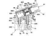
FIG. 1 shows a schematic configuration of an endoscope system according to the embodiment. The endoscope system 1 includes an
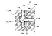
内視鏡2は、術者が操作をする内視鏡操作部10と、内視鏡操作部10の先端から延び、可撓性を有する長尺の内視鏡挿入部11とを有する。内視鏡操作部10には、アングルノブや各種のボタン、スイッチが配設されており、ユニバーサルケーブル12を介してコントロールユニット4に接続される。内視鏡2の内部には、吸引管路20が形成されている。吸引管路20は、内視鏡挿入部11の先端部に先端開口部21を有し、内視鏡操作部10内まで延びる第一の管路部20Aと、第一の管路部20Aの基端に設けられた分岐部22と、分岐部22から内視鏡操作部10内を通ってユニバーサルケーブル12に引き込まれる第二の管路部20Bとからなり、第二の管路部20Bの基端部24が吸引器5に接続されている。なお、内視鏡2には、図示しないその他の管路を設けることも可能である。 The
内視鏡操作部10は、吸引管路20の分岐部22よりも基端側の第二の管路部20Bに回収用装着部25が凹設されている。回収用装着部25の開口部は、内視鏡操作部10の外周から径方向外側に突出し、開口部の外周にはツバ25Aが環状に形成されている。図2に示すように、回収用装着部25には、開口部を密封するように組織回収装置3が着脱自在に取り付けられる。組織回収装置3は、回収用装着部25の開口部を密閉する蓋部31を有する。蓋部31には、回収用装着部25のツバ25Aに係止するツメ31Aと、術者が掴むツマミ31Bとが形成されている。蓋部31の内面側には、フィルタ部32が延設されている。フィルタ部32は、メッシュ構造を有し、吸引管路20を横断するように延びている。メッシュは、多数の孔が吸引管路20に略平行になるように形成されており、吸引管路20に臨む表面と、表面に対する裏面とがそれぞれ組織捕捉面となる。なお、回収用装着部25とフィルタ部32との間の隙間は、組織が通過できない程度の大きさになっている。 In the
吸引管路20の分岐部22には、作業用チャンネル23の先端側開口部26が連結されている。作業用チャンネル23の基端側接続口27は、内視鏡操作部10の側部28に形成されている。基端側接続口27には、栓35が装着されている。栓35には、作業用チャンネル23に連通可能な孔36が形成されており、この孔36が処置具挿入口37を形成する。栓35は、例えば、弾性部材から製造されており、処置具を挿入していない状態では、孔36が密閉される。なお、作業用チャンネル23は、処置具を挿入したときに、吸引管路20の第一の管路部20Aに処置具が挿入され、吸引管路20の先端開口部21から処置具が突出するように吸引管路20の分岐部22に接続されている。 A distal end
次に、この実施の形態の作用について説明する。
まず、内視鏡挿入部11を患者の口から挿入し、組織を採取する部位に導く。組織を切除するときには、処置具(例えば、切除鉗子、スネアなど)を処置具挿入口37から挿入する。処置具は、栓35の処置具挿入口37から作業用チャンネル23の基端側接続口27に挿入され、分岐部22の形状に倣って先端側開口部26から吸引管路20の先端側に導かれる。さらに、吸引管路20に沿って内視鏡挿入部11内に進み、先端開口部21から突出する。処置具が切除鉗子である場合には、先端に設けられた一対の鉗子片を開閉させて採取対象となる組織を切除する。切除が終了したら切除鉗子を内視鏡2から抜き取る。処置具は、吸引管路20から分岐部22を経て、作業用チャンネル23から抜き出される。栓35の処置具挿入口37は、自己に復元力によって塞がる。Next, the operation of this embodiment will be described.
First, the
組織を回収するときには、吸引器5を運転させる。組織回収装置3と吸引管路20とは気密が保たれており、作業用チャンネル23側は、栓35で気密が保たれているので、吸引管路20の先端開口部21には、図1に矢印で示すように吸引力が作用し、切除された組織が吸引管路20内に引き込まれる。吸引管路20内では、組織は矢印に示すように分岐部22を通って回収用装着部25に導かれる。回収用装着部25には、組織回収装置3が装着されており、フィルタ部32のメッシュ構造は、流体は通過させるが、組織は通過させないので、図2に仮想線で示すように組織がフィルタ部32に引っ掛かる。吸引器5を停止させてから、組織回収装置3を回収用装着部25から取り外すと、フィルタ部32に捕捉された組織が回収される。 When the tissue is collected, the
この実施の形態によれば、内視鏡2側に組織回収装置3を直接装着する構成にしたので、内視鏡操作部10から外部に伸びる管路の数を減少させることができる。さらに、組織回収装置3が内視鏡2に対して固定されるので、組織回収装置3の取り扱いが容易になる。これらのことから、術者の負担を低減でき、手技を速やかに実施することが可能になる。さらに、組織回収装置3は、処置具を抜き差しする管路である作業用チャンネル23から分岐した管路(吸引管路20の分岐部22よりも基端部側)に設けられているので、処置具の抜き差しが容易になる。 According to this embodiment, since the tissue collection device 3 is directly mounted on the
(第2の実施の形態)
図3から図23を参照して第2の実施の形態について説明する。なお、第1の実施形態と同じ構成要素には同一の符号を付してある。また、重複する説明は省略する。
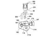
図3及び図4に示すように、内視鏡システム51は、内視鏡52と、コントロールユニット4と、吸引器5と、内視鏡52に着脱自在なアタッチメント53と、アタッチメント53を介して内視鏡52に固定される組織回収装置54とを備える。(Second Embodiment)
A second embodiment will be described with reference to FIGS. In addition, the same code | symbol is attached | subjected to the same component as 1st Embodiment. In addition, overlapping explanation is omitted.
As shown in FIGS. 3 and 4, the
内視鏡52には、管路の構成のみが第1の実施の形態と異なる内視鏡操作部60と内視鏡挿入部61とを有する。この内視鏡52内には、作業用チャンネル65と、吸引管路66とが形成されている。作業用チャンネル65は、内視鏡挿入部61の先端部に先端開口部65Aを有し、内視鏡操作部60の側部67まで延びている。作業用チャンネル65の基端側接続口は、側部67から突出して第一の接続部68を形成する。側部67には、吸引管路66の先端部66Aも開口している。この開口は、側部67から突出する第二の接続部69に形成されている。吸引管路66は、内視鏡操作部60からユニバーサルケーブル12内を通り、その基端部66Bが吸引器5に接続されている。第一の接続部68と、第二の接続部69とは、略平行に側部67から突出している。 The
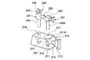
第一、第二の接続部68,69には、アタッチメント53が装着されている。アタッチメント53は、例えば、樹脂、弾性材料などのように内視鏡52側に比べて硬度及び強度が低い材料から製造されている。図4から図6に示すように、アタッチメント53は、作業用チャンネル65の一部をなす第一の連結管路70がアタッチメント53の上面53Aから面53Bに貫通するように形成されている。第一の連結管路70は、下面53B側では第一の接続部68を嵌め込み可能な形状を有する。第一の連結管路70の上面53A側には、処置具挿入口71が形成されている。さらに、第一の連結管路70の管路中には、分岐部72が形成されており、ここから第一の接続管路73が延びている。第一の接続管路73は、アタッチメント53の側面53Cに開口しており、この開口部が先端側接続口74となる。第一の接続管路73の管路中には、バイパス管路75が接続されている。バイパス管路75は、第二の接続管路76を貫通して、アタッチメント53の側面53Dに開口している。バイパス管路75は、アタッチメント53の下面53Bを下向きに配置したときに、第一の接続管路73側が第二の接続管路76側よりも相対的に高くなるような勾配を有する。バイパス管路75の径は、第一、第二の接続管路73,76の径よりも小さい。 An
第二の接続管路76は、第一の接続管路73と略平行に延びており、一方の端部はアタッチメント53の側面53Cに基端側接続口77を形成する。他方の端部は、アタッチメント53内において、第二の連結管路78に接続されている。第二の連結管路78は、アタッチメント53の下面53Bのみに開口部を有する。この開口部は、内視鏡52側の第二の接続部69を嵌め込み可能な形状を有する。 The
アタッチメント53の先端側接続口74と基端側接続口77とには、組織回収装置54が着脱自在に装着される。図4及び図7〜図9に示すように、組織回収装置54は、組織回収用ケース80と、組織回収用ケース80に着脱自在な組織回収用フィルタ81とを有する。組織回収用ケース80は、内部を目視で確認できる材料から製造された有底筒形のケース本体82を有する。ケース本体82の側部には、開口部83側から順番に先端側管路84と基端側管路85とが、ケース本体82に対して斜めに、かつ互いに平行に延びている。先端側管路84は、その外周に環状突起84Aと、環状突起84Aより大径の環状突起84Bとが順番に凸設されている。基端側管路85は、その外周に環状突起85Aと、環状突起85Aより大径の環状突起85Bとが順番に凸設されている。これら管路84,85は、ケース本体82の内部に連通している。 A
ケース本体82は、円形の開口部83を有し、開口部83の外周には一対の係止突起83Aが設けられている。係止突起83Aは、開口部83の一直径上に配置されている。ケース本体82の開口部83の内側は、ケース本体82の底部82Bに向かって縮径するテーパ面83Bを有する。ケース本体82の開口部83よりも底部82B側には、蓋86が挿入されている。蓋86は、シール材87によってケース本体82の内壁との間で気密を保持しながらケース本体82の長手方向に摺動自在になっている。ここで、ケース本体82の内周側には、連通用の溝88が長手方向に沿って1本形成されており、この溝88の途中に蓋86がある場合には、蓋86の上面からケース本体82の開口部83までの空間89Aと、蓋86の底面からケース本体82の底部82Bまでの空間89Bとを連通させることができる。溝88は、底部82Bから先端側管路84の接続位置の手間まで延びている。蓋86とケース本体82の底部82Bとの間には、付勢手段であるコイルバネ90が挿入されており、蓋86は開口部83に向けて付勢されている。図9に示すように、無負荷状態では、蓋86がテーパ面83Bによって形成される段差部91に突き当たるので、これ以上は外に出ない。この位置では、ケース本体82の内部が先端側管路84及び基端側管路85に連通し、開口部83は蓋86によって密封される。 The
図7及び図8、図10に示すように、組織回収用フィルタ81は、ケース本体82の開口部83に挿入可能な蓋部95を有し、蓋部95からフィルタ部96が延設されている。蓋部95は、一対の固定部97が設けられている。これら固定部97は、ケース本体82の係止突起83Aにクリック的に係止可能である。また、蓋部95には、シール材であるOリング98が装着されており、テーパ面83Bに押し潰されてケース本体82の開口部83を密封するようになっている。フィルタ部96は、流体は通過可能であるが、組織は引っ掛かるメッシュ形状を有する。フィルタ部96は、2つの組織捕捉面96Aを表裏一体に有する。組織捕捉面96Aは、一対の固定部97を結ぶ線分に対して略直角に配置されている。したがって、ケース本体82側の係止突起83Aに固定部97を係止させると、常にいずれか一方の組織捕捉面96Aが先端側管路84に臨んで配置されるようになるので、組織回収用フィルタ81は、向きに関係なく取り付け可能である。フィルタ部96とケース本体82との隙間は、組織が通過できない大きさである。 As shown in FIGS. 7, 8, and 10, the
フィルタ部96の先端には、プレート100が設けられている。図11に示すように、このプレート100には、切り欠き101が設けられており、組織回収用フィルタ81を取り外すときにケース本体82内の液体をかき出さないようにしている。図7に示すように、組織回収用フィルタ81を組織回収用ケース80に装着したときには、フィルタ部96の先端のプレート100が蓋86を底部82B側に押し戻す。フィルタ部96は、蓋86が先端側管路84と基端側管路85との間に相当する位置にくるようにコイルバネ90に抗して蓋86を押し戻す。 A
図12に示すように、アタッチメント53に組織回収装置54を装着すると、先端側管路84が第一の接続管路73に挿入される。先端側管路84がバイパス管路75の連結位置を越えて分岐部72に向かって進入する。環状突起84Aは、第一の接続管路73の環状溝73Aに係止され、環状突起84Bは側面53Cに突き当たる。これによって、第一の連結管路70と、組織回収装置54の空間89Aとが連通する。ここには、組織回収用フィルタ81のフィルタ部96が挿入される。同様に、基端側管路85が第二の接続管路76に挿入され、先端部がバイパス管路75を越える。環状突起85Aは環状溝76Aに係止され、環状突起85Bは側面53Cに突き当たる。これによって、第二の連結管路78と、組織回収装置54の空間89Bとが連通する。 As shown in FIG. 12, when the
蓋86は、ケース本体82の溝88の途中にあるので、溝88及び空間89A,89Bを通して、第一の連結管路70と第二の連結管路78とが連通する。なお、先端側管路84と基端側管路85とは、それぞれバイパス管路75の形成位置を越えて挿入されているので、バイパス管路75は遮断されている。先端側管路84の長さは、基端側管路85の長さよりも長いので、組織回収装置54は、底部82B側よりも開口部83側の方がアタッチメント53から離れるように傾斜して固定される。 Since the
組織回収装置54をアタッチメント53から取り外すと、バイパス管路75が開通する。先端側接続口74と基端側接続口77とは、それぞれ別々に外部に対して開放される。組織回収装置54をアタッチメント53から取り外したときには、図13に示すような栓体110をアタッチメント53に装着して、先端側接続口74と、基端側接続口77と、バイパス管路75の側面53D側とを外部に対して閉鎖することができる。栓体110は、術者が把持する把持部111と、第一、第二の接続管路73,76に一つずつ嵌め込まれる先端側突起112(第一の栓体)と、基端側突起126(第二の栓体)とを有する。これら突起112,126のそれぞれの外周には、環状溝74A,77Aに係止される環状突起112A,126Aが突設されている。先端側突起112は、バイパス管路75の手前で停止するが、基端側突起126はバイパス管路75を越えて第二の連結管路78に向かって進入する。基端側突起126は、中空形状を有し、その一部にバイパス管路75に連通する孔114が形成されている。したがって、栓体110をアタッチメント53に装着した状態では、第一の接続管路73と第二の接続管路76とがバイパス管路75を介して連通する。なお、先端側突起112と、基端側突起126とは、分離した2つの栓体であっても良い。 When the
この実施の形態の作用について説明する。
最初に、図12に示すように、アタッチメント53に組織回収装置54を装着する。さらに、アタッチメント53の第一、第二の連結管路70,78に、内視鏡操作部60の第一、第二の接続部68,69をそれぞれ嵌入させて、アタッチメント53を内視鏡52に固定する。このとき、図4に示すように、アタッチメント53は、側面53E(第一の面)を内視鏡操作部60に向けて装着する。これによって、側面53C(第二の面)側に装着された組織回収装置54は、アタッチメント53を挟んで内視鏡操作部60の反対側に配置される。この状態で、内視鏡挿入部61を体内に挿入し、アタッチメント53の処置具挿入口71から処置具(例えば、切除鉗子)を挿入する。処置具は、アタッチメント53の第一の連結管路70から内視鏡52側の作業用チャンネル65に進入し、内視鏡挿入部61の先端部から突出させる。処置具で採取対象となる組織を切除したら、処置具を内視鏡52、及びアタッチメント53から抜き取る。処置具挿入口71は自己の復元力で閉じて密閉される。The operation of this embodiment will be described.
First, as shown in FIG. 12, the
切除した組織を吸引するときには、吸引器5を運転させる。吸引管路66(アタッチメント53の第二の連結管路78及び第二の接続管路76を含む)と、組織回収装置54と、第一の接続管路73と、作業用チャンネル65(第一の連結管路70を含む)とを通じて、吸引力が組織に作用する。図3に矢印で示すように、組織は、周囲の流体と共に作業用チャンネル65から分岐部72に至り、分岐部72から第一の接続管路73に導かれ、組織回収装置54の空間89Aに引き込まれる。組織は、空間89A内のフィルタ部96の組織捕捉面96Aに引っ掛かる。流体は、フィルタ部96のメッシュを通り、溝88から空間89Bに導かれ、アタッチメント53から吸引管路66を通って吸引器5から排出される。組織を捕捉したら吸引器5を停止させる。組織回収用フィルタ81を組織回収用ケース80から取り外して組織を回収する。 When the excised tissue is aspirated, the
組織回収装置54は、左右方向には開口部83側がアタッチメント53から離れる方向に傾斜しているので、組織回収用フィルタ81は、内視鏡操作部60に干渉することなく簡単に取り外せる。この際に、一対の固定部97を互いに近接するように掴むだけで、組織回収用ケース80と係合が解除されるので、片手で組織回収用フィルタ81の取り外しができる。また、上下方向には、開口部83側が上向きに傾斜しているので、液体がケース本体82に残留していた場合でも液体が外部に流出することはない。液体が多く残留していた場合には、組織回収用フィルタ81のプレート100に切り欠き101があるので、液体をケース本体82外にかき出すことはない。組織回収用フィルタ81が取り外されると、コイルバネ90の付勢力によって蓋86が開口部83側の段差部91に当接するまで上昇する。その結果、蓋86のシール材87でケース本体82が密閉される。 Since the
この実施形態によれば、処置具の挿入に使用するアタッチメント53を介して組織回収装置54を内視鏡52に接続するように構成されているので、組織回収装置54のための管路を外部に引き回さないで済み、術者が内視鏡52を操作し易くなる。組織回収装置54は、内視鏡操作部60の近傍に固定されるので、術者が組織回収装置54を扱い易くなる。組織回収装置54は、内視鏡52に干渉しない位置に取り付けられているので、操作性が良い。組織回収装置54は、開口部83が上になるように傾斜しているので、取り外しが容易な上に、内部の液体が流出し難くなる。組織回収用フィルタ81は、組織回収用ケース80に対してクリック的に着脱できるので、内視鏡52を持ったままで取り外すなどの操作が容易になる。また、これによって、組織回収用フィルタ81を複数回着脱して連続して組織を回収する操作が楽になる。組織回収用フィルタ81を取り外した状態では、蓋86がケース本体82内部を密閉するので、通路内の気密を保つことができる。 According to this embodiment, since the
アタッチメント53は、分岐部72で作業用チャンネル65の途中から分岐させた管路に組織回収装置54を接続したので、処置具の挿抜が容易になる。組織回収装置54を取り外した状態で、栓体110(図13参照)を装着すると、管路の気密を保つことができる。また、バイパス管路75を通じて作業用チャンネル65と吸引管路66とを連通させることができる。バイパス管路75を側面53Dに開口させたので、洗浄ブラシを挿入しての洗浄が容易である。アタッチメント53を弾性部材で製造したので内視鏡2への着脱が容易であると共に、気密構造を構築し易い。また、アタッチメント53は、内視鏡2に比べて比較的に柔らかい材料で構成されているので、着脱などを繰り返すことによっても内視鏡2が磨耗し難くなっている。このため、内視鏡システム1全体としてのコストを低下できる。 In the
この実施の形態の変形例について以下に説明する。
図14に示すアタッチメント120は、側面53Dに開口しないバイパス管路121を有する。このアタッチメント120に適用される栓体125は、把持部111と、先端側突起112(第一の栓体)と、基端側突起126(第二の栓体)とを有する。基端側突起126の長さは、基端側接続口77からバイパス管路121の合流位置までの長さよりも短い。基端側突起126は、環状突起126Aによって第二の接続管路76に係止される。作業用チャンネル65は、第一の接続管路73、バイパス管路121、第二の接続管路76を介して吸引管路66に連通される。A modification of this embodiment will be described below.
The
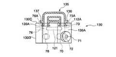
図15及び図16に示すアタッチメント130は、バイパス管路を有しない。組織回収装置54を取り外したときには、連結管135(連結部材)が装着される。連結管135は、両端部が先端側接続部136と、基端側接続部137とになっている。これら接続部136,137は、第一、第二の接続管路73,76に嵌め込まれる。このような連結管135は、樹脂や、弾性部材等で製造される。連結管135を装着すると、先端側接続口74と基端側接続口77が外部に対して密封され、第一の接続管路73、連結管135、第二の接続管路76を介して作業用チャンネル65と吸引管路66とが連通される。 The
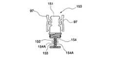
図17に示す組織回収用フィルタ140は、フィルタ部141にスリット142がコ字状に入っている。スリット142は、メッシュに垂直な組織捕捉面96A内に形成されており、スリット142で囲まれた領域が可動部143になっている。図18に示すように、組織を捕捉した状態で可動部143を指で押すと、捕捉された組織を簡単に離脱できる。可動部143の他の形態としては、図19に示すものがある。この組織回収用フィルタ150は、本体部151から枠体152が延設している。枠体152の内周には、溝153が内周に沿って形成されており、ここに可動部154が挿入されている。可動部154は、メッシュ構造を有し、流体は通過させるが、組織は捕捉される組織捕捉面154Aが表面と裏面のそれぞれに形成される。可動部154の外形寸法に対して溝153は遊びを持っているので、可動部154を手で動かして組織を離脱させることができる。 The
また、図20から図23に示すような作業用チャンネル65の先端開口部を使用しても良い。図20及び図21に示す作業用チャンネル65の先端開口部160は、作業用チャンネル65の外径に対して、角度αの傾斜角を有するテーパ面161から形成され、先端側が拡径されている。ここで、角度αは、0°よりも大きく5°以下の角度である。0°以下では、比較的に大きい組織の場合には、組織が作業用チャンネル65に入り難くなる。5°を越えると、テーパ面161に組織が詰まり易くなる。図22及び図23に示す先端開口部162は、傾斜角度βのテーパ面163を有する。テーパ面163は、作業用チャンネル65の軸線に対して偏心している。傾斜角度βは、0°よりも大きく5°以下である。その理由及び先端開口部162の作用は、図20に示す形態と同じである。 Further, a tip opening portion of the working
(第3の実施の形態)
図24から図29を参照して第3の実施の形態を説明する。第3の実施の形態は、アタッチメント及び組織回収装置の変形例を示す。前記の各実施形態と同じ構成要素には同一の符号を付してある。また、重複する説明は省略する。
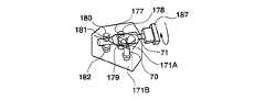
図24に示すように、アタッチメント170は、本体部171と、本体部171に回転自在に挿入される弁体172とを有する。本体部171は、第一の連結管路70を有し、第一の連結管路70には上面171Aに開口する処置具挿入口71が設けられると共に、分岐部72から第一の接続管路73が分岐している。第一の接続管路73は、弁体172が挿入される挿入孔173に連通している。挿入孔173は、大径部175と小径部176とを有する。本体部171において、挿入孔173の大径部175には第一の接続管路73が開口している。さらに、第一の接続管路73の接続位置から周方向に約90°回転した位置には、孔177が形成されている。孔177は、上面171Aに開口すると共に、挿入孔173を越えて下面171Bに向かって延びているが、下面171Bには貫通していない。孔177の挿入孔173から上側が先端側開口部178となり、孔177の挿入孔173から下側が嵌入孔179になる。挿入孔173の小径部176には、貫通孔180が形成されている。貫通孔180において挿入孔173よりも上面171A側は、基端側接続口181となる。挿入孔173の下面171B側は、第二の連結管路182になる。(Third embodiment)
A third embodiment will be described with reference to FIGS. The third embodiment shows a modification of the attachment and the tissue collection device. The same components as those in the above embodiments are denoted by the same reference numerals. In addition, overlapping explanation is omitted.
As shown in FIG. 24, the
弁体172は、挿入孔173に気密を保持しつつ軸線回りに回転自在に挿入される。弁体172は、細径の先端部185と、大径の基端部186とを有する。基端部186には、術者が弁体172を回転させるためのツマミ187が設けられている。弁体172内にはバイパス管路188が形成されている。バイパス管路188は、基端部186側が封鎖されている。 The
弁体172の基端部186には、同軸上に形成された2つの貫通孔191,192と、これら貫通孔191,192に直交する位置に形成された貫通孔193とを有する。この弁体172を、図24に示す回転位置(第一の回転位置)で本体部171に挿入した場合には、図26に示すように、貫通孔191が先端側開口部178とバイパス管路188とを連通させ、貫通孔192が嵌入孔179とバイパス管路188を連通させる。貫通孔193は、第一の接続管路73とバイパス管路188を連通させる。なお、図26に示す回転位置から矢印で示す時計回りに90°回転させた位置(第二の回転位置)では、貫通孔191が第一の接続管路73につながり、貫通孔193が嵌入孔179につながる。貫通孔192は、封鎖される。 The
同様に、図24に示す弁体172の先端部185には、同軸上に形成された2つの貫通孔195,196と、これら貫通孔195,196に直交する位置に形成された貫通孔197とを有する。この弁体172を、図24に示す第一の回転位置で本体部171に挿入した場合には、図27に示すように、貫通孔195が基端側接続口181とバイパス管路188とを連通させ、貫通孔196が第二の連結管路182とバイパス管路188を連通させる。貫通孔197は、本体部171によって封鎖される。なお、図26に示す回転位置から矢印で示す時計回りに90°回転させた第二の回転位置では、貫通孔195及び貫通孔196が本体部171で封鎖され、貫通孔197が第二の連結管路182につながる。 Similarly, the
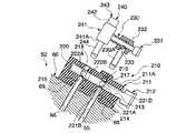
図28にアタッチメント170と共に用いる組織回収装置200を示す。組織回収装置200は、組織回収用ケース201と、組織回収用フィルタ81とを有する。組織回収用ケース201は、ケース本体82から先端側管路202と、基端側管路203とが軸線方向に所定の間隔で配置されている他は、第二の実施の形態と同じ構成である。先端側管路202と、基端側管路203とは、それぞれが屈曲した後に、平行に延びている。先端側管路202の側部は、所定位置に内部と外部を連通させる接続管路204が形成されている。 FIG. 28 shows a
組織回収装置200を装着しないときには、弁体172を第二の回転位置に設定する。第一の連結管路70が弁体172のバイパス管路188を通じて第二の連結管路182に連結される。弁体172の他の貫通孔192,193,195,196は、本体部171によって封鎖されるので、外部との気密を保ちながら、作業用チャンネル65と吸引管路66とが連通される。 When the
図29に示すように、組織回収装置200をアタッチメント170に装着するときには、弁体172を第一の回転位置に設定する。先端側管路202は、先端側開口部178に挿入され、弁体172を貫通して嵌入孔179に嵌め込まれる。このとき、先端側管路202の接続管路204と第一の接続管路73とが連通する。基端側管路203は、基端側接続口181に挿入され、弁体172を貫通して第二の連結管路182に嵌め込まれる。基端側接続口181と第二の連結管路182とで気密構造が形成されるので、バイパス管路188は封鎖され、組織回収装置200を通る管路で第一の連結管路70と第二の連結管路182とが連通する。 As shown in FIG. 29, when attaching the
このアタッチメント170及び組織回収装置200を用いて組織を回収するときは、アタッチメント170を内視鏡52に装着する。作業用チャンネル65(第一の連結管路70を含む)と、吸引管路66(第二の連結管路182を含む)とが組織回収装置200を介して連通される。この後の操作は、第二の実施の形態と同様にして行う。組織は、作業用チャンネル65から、分岐部72を経て第一の接続管路73、先端側管路202を通り、フィルタ部96(図8参照)に捕捉される。流体は、基端側管路203から排出され、吸引管路66に吸引される。 When the tissue is recovered using the
この実施の形態によれば、処置具の挿入に使用するアタッチメント170を介して組織回収装置200を内視鏡52に接続したので、組織回収装置200のための管路が外部に引き回されることがなく、術者が内視鏡52を操作し易い。組織回収装置200は、内視鏡操作部60の近傍に固定されることになるので、術者が組織回収装置200を扱い易くなる。
組織回収装置200を取り外したときには、弁体172を回転させれば別体の栓体を装着しなくても、管路を外部に対して密閉することができる。さらに、作業用チャンネル65と吸引管路66とをバイパス管路188を介して連通させることができる。したがって、組織回収装置200を取り外したときの操作を簡略化できる。According to this embodiment, since the
When the
なお、本発明は、前記の各実施の形態に限定されずに広く応用することができる。
例えば、組織回収装置は、内視鏡2又はアタッチメント53,170に装着可能な構成であれば良く、各実施形態の組織回収装置3,54,200の構成に限定されない。The present invention can be widely applied without being limited to the above-described embodiments.
For example, the tissue recovery device may be configured to be attached to the
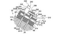
本発明と同様の課題を解決することができる他のアタッチメントと組織回収装置の例を図30から図33に示す。
図30及び図31に示すアタッチメント210は、本体部211に弁体212が回転自在に挿入されている。弁体212が挿入される挿入穴213を通るように第一の連結管路214と、第二の連結管路215とが平行に本体部211を貫通している。本体部211の上面211Aに開口する第一の連結管路214の先端開口部216には、鉗子栓蓋217が着脱自在に設けられている。また、上面211Aにおける第二の連結管路215の開口は、基端側接続口218になる。弁体212は、挿入穴213に気密を保ちながら回転自在に挿入されている。弁体212は、内部にバイパス管路220が形成されている。弁体212の基端側には、第一の連結管路214に相当する位置に、4つの貫通孔221A,221B,221C,221Dが弁体212の周方向に等間隔に形成されている。さらに、弁体212の先端側には、第二の連結管路215に相当する位置に、3つの貫通孔222A,222B,222Cが形成されている。貫通孔222Aと貫通孔222Cとは同軸線上に配置されており、貫通孔222Bは、2つの貫通孔222A,222Cから90°ずれた位置に形成されている。Examples of other attachments and tissue recovery devices that can solve the same problems as those of the present invention are shown in FIGS.
In the
図32に示すように、弁体212が第一の回転位置にあるときは、貫通孔221Bによって第一の連結管路214とバイパス管路220とが接続される。第二の連結管路215では、貫通孔222Bによって吸引管路66のみがバイパス管路220に接続される。その結果、作業用チャンネル65と吸引管路66とがバイパス管路220を介して連結される。残りの貫通孔222A,222Cは、本体部211によって封鎖される。この場合には、鉗子栓蓋217を装着すると、先端開口部216及び貫通孔221が外部から隔離される。鉗子栓蓋217を取り外すと、鉗子などの処置具を挿入可能になる。図31に示すように、第二の回転位置では、第一、第二の連結管路214,215は、それぞれが連通し、かつ各連結管路214,215がバイパス管路220を通って連通する。ここに図33に示すように、接続管路230を備える組織回収装置240を装着すると、作業用チャンネル65と吸引管路66とが組織回収装置240の内部管路を介して接続され、バイパス管路220が閉鎖される。ここで、組織回収装置240は、組織回収用ケース241と、組織回収用ケース241の開口部242から挿入される組織回収用フィルタ243とを有し、組織回収用ケース241の底部241Aには、基端側管路244が設けられている。組織回収用ケース241の側部には接続管路230が接続されている。接続管路230は、組織回収用ケース241の内部に連通する管路で、L字状に折れ曲がっている。接続管路230の角部には、弁体231が回転自在に挿入されている。弁体231は、接続管路230の角部を覆うゴム製の支持部232に回転自在に装着されており、外部に対して気密が保たれている。弁体231は、内部が中空で貫通孔233が1箇所形成されている。貫通孔233を接続管路230の挿入側の管路230Aに合わせると、接続管路230が連通し、組織を回収できるようになる。弁体231を回転させて貫通孔233の位置をずらすと、接続管路230が封鎖される。 As shown in FIG. 32, when the
組織回収装置240を装着した状態で吸引器5(図3参照)を運転させると、組織は、作業用チャンネル65から接続管路230を経て組織回収装置240内に導かれ、図8と同様の構成を有するフィルタ部に捕捉される。流体は、さらに基端側管路244から吸引管路66を経て排出される。 When the aspirator 5 (see FIG. 3) is operated with the
1,51 内視鏡システム
2,52 内視鏡
3,54,200 組織回収装置
10,60 内視鏡操作部
11,61 内視鏡挿入部
20,66 吸引管路
22,72 分岐部
23,65 作業用チャンネル
53,120,130,170 アタッチメント
53C 側面(第二の面)
53E 側面(第一の面)
70 第一の連結管路(作業用チャンネル)
73 第一の接続管路
74 先端側接続口
75,121,188 バイパス管路
76 第二の接続管路
77 基端側接続口
78 第二の連結管路(吸引管路)
80 組織回収用ケース
81,140 組織回収用フィルタ
96A 組織捕捉面
112 先端側突起(第一の栓体)
126 基端側突起(第二の栓体)
135 連結管(連結部材)
172 弁体DESCRIPTION OF
53E Side (first side)
70 First connecting pipe (working channel)
73
80 Tissue recovery case 81,140
126 Proximal projection (second plug)
135 Connecting pipe (connecting member)
172 Disc
Claims (12)
Translated fromJapanese前記内視鏡挿入部の先端部に先端開口が形成され前記内視鏡内を通って基端部が吸引器に接続される管路と、
を備え、
前記管路は、
前記内視鏡操作部に中間開口が形成され前記中間開口から前記先端開口へ向けて処置具を挿入可能な作業用チャンネルと、
前記内視鏡操作部において一端が前記作業用チャンネルと連通され他端が前記基端部として前記吸引器に接続された吸引管路と、
を有し、
前記内視鏡操作部には、前記管路の前記基端部からの前記吸引器による吸引方向において前記作業用チャンネルよりも下流に、前記先端開口から前記管路を通じて前記吸引器側へ向かって吸引される組織を捕捉可能な組織回収装置が設けられ、
前記作業用チャンネルと前記吸引管路とが分岐される分岐部が前記内視鏡操作部に接続され、
前記組織回収装置は、前記分岐部と前記吸引管路との間に介在されている
ことを特徴とする内視鏡システム。An endoscope having an endoscope operation unit operated by an operator and an endoscope insertion unit extending from the endoscope operation unit and inserted into the body;
A pipe line in which a distal end opening is formed at a distal end portion of the endoscope insertion portion, and a proximal end portion is connected to an aspirator through the endoscope;
With
The pipeline is
A working channel in which an intermediate opening is formed in the endoscope operation section and a treatment tool can be inserted from the intermediate opening toward the distal end opening;
A suction conduit having one end communicating with the working channel in the endoscope operation section and the other end connected to the suction device as the base end;
Have
The endoscope operation section includes a downstream side of the working channel in the suction direction by the suction device from the proximal end portion of the conduit, and a direction from the distal end opening toward the suction device through the conduit. A tissue collection device capable of capturing the tissue to be aspirated is provided;
A branch portion where the working channel and the suction pipe are branched is connected to the endoscope operation portion,
The endoscope system according to claim 1,wherein the tissue collection device is interposed between the branch portion and the suction conduit .
Priority Applications (3)
| Application Number | Priority Date | Filing Date | Title |
|---|---|---|---|
| JP2006021961AJP4932266B2 (en) | 2006-01-31 | 2006-01-31 | Endoscope system |
| US11/698,522US8262565B2 (en) | 2006-01-31 | 2007-01-26 | Endoscope system |
| EP07001871.8AEP1813184B1 (en) | 2006-01-31 | 2007-01-29 | Endoscope system |
Applications Claiming Priority (1)
| Application Number | Priority Date | Filing Date | Title |
|---|---|---|---|
| JP2006021961AJP4932266B2 (en) | 2006-01-31 | 2006-01-31 | Endoscope system |
Publications (2)
| Publication Number | Publication Date |
|---|---|
| JP2007202630A JP2007202630A (en) | 2007-08-16 |
| JP4932266B2true JP4932266B2 (en) | 2012-05-16 |
Family
ID=37969970
Family Applications (1)
| Application Number | Title | Priority Date | Filing Date |
|---|---|---|---|
| JP2006021961AExpired - Fee RelatedJP4932266B2 (en) | 2006-01-31 | 2006-01-31 | Endoscope system |
Country Status (3)
| Country | Link |
|---|---|
| US (1) | US8262565B2 (en) |
| EP (1) | EP1813184B1 (en) |
| JP (1) | JP4932266B2 (en) |
Families Citing this family (43)
| Publication number | Priority date | Publication date | Assignee | Title |
|---|---|---|---|---|
| US6872178B2 (en)* | 2002-11-18 | 2005-03-29 | Andrew Mark Weinberg | Colonoscope apparatus and method |
| US8382660B2 (en) | 2008-03-13 | 2013-02-26 | Olympus Medical Systems Corp. | Endoscope system having an endoscope and a tissue-collecting apparatus |
| US9901244B2 (en) | 2009-06-18 | 2018-02-27 | Endochoice, Inc. | Circuit board assembly of a multiple viewing elements endoscope |
| US10165929B2 (en) | 2009-06-18 | 2019-01-01 | Endochoice, Inc. | Compact multi-viewing element endoscope system |
| US9101287B2 (en) | 2011-03-07 | 2015-08-11 | Endochoice Innovation Center Ltd. | Multi camera endoscope assembly having multiple working channels |
| US9492063B2 (en) | 2009-06-18 | 2016-11-15 | Endochoice Innovation Center Ltd. | Multi-viewing element endoscope |
| US8926502B2 (en) | 2011-03-07 | 2015-01-06 | Endochoice, Inc. | Multi camera endoscope having a side service channel |
| US12137873B2 (en) | 2009-06-18 | 2024-11-12 | Endochoice, Inc. | Compact multi-viewing element endoscope system |
| US9642513B2 (en) | 2009-06-18 | 2017-05-09 | Endochoice Inc. | Compact multi-viewing element endoscope system |
| US9402533B2 (en) | 2011-03-07 | 2016-08-02 | Endochoice Innovation Center Ltd. | Endoscope circuit board assembly |
| US9713417B2 (en) | 2009-06-18 | 2017-07-25 | Endochoice, Inc. | Image capture assembly for use in a multi-viewing elements endoscope |
| US9706903B2 (en) | 2009-06-18 | 2017-07-18 | Endochoice, Inc. | Multiple viewing elements endoscope system with modular imaging units |
| US11547275B2 (en) | 2009-06-18 | 2023-01-10 | Endochoice, Inc. | Compact multi-viewing element endoscope system |
| US11278190B2 (en) | 2009-06-18 | 2022-03-22 | Endochoice, Inc. | Multi-viewing element endoscope |
| US9101268B2 (en) | 2009-06-18 | 2015-08-11 | Endochoice Innovation Center Ltd. | Multi-camera endoscope |
| US11864734B2 (en) | 2009-06-18 | 2024-01-09 | Endochoice, Inc. | Multi-camera endoscope |
| WO2010146587A1 (en) | 2009-06-18 | 2010-12-23 | Peer Medical Ltd. | Multi-camera endoscope |
| US9872609B2 (en) | 2009-06-18 | 2018-01-23 | Endochoice Innovation Center Ltd. | Multi-camera endoscope |
| US12220105B2 (en) | 2010-06-16 | 2025-02-11 | Endochoice, Inc. | Circuit board assembly of a multiple viewing elements endoscope |
| US9560953B2 (en) | 2010-09-20 | 2017-02-07 | Endochoice, Inc. | Operational interface in a multi-viewing element endoscope |
| EP2618718B1 (en) | 2010-09-20 | 2020-04-15 | EndoChoice Innovation Center Ltd. | Multi-camera endoscope having fluid channels |
| CN103403605A (en) | 2010-10-28 | 2013-11-20 | 恩多巧爱思创新中心有限公司 | Optical systems for multi-sensor endoscopes |
| US12204087B2 (en) | 2010-10-28 | 2025-01-21 | Endochoice, Inc. | Optical systems for multi-sensor endoscopes |
| US11889986B2 (en) | 2010-12-09 | 2024-02-06 | Endochoice, Inc. | Flexible electronic circuit board for a multi-camera endoscope |
| US9320419B2 (en) | 2010-12-09 | 2016-04-26 | Endochoice Innovation Center Ltd. | Fluid channeling component of a multi-camera endoscope |
| CN107361721B (en) | 2010-12-09 | 2019-06-18 | 恩多巧爱思创新中心有限公司 | Flexible electronic circuit boards for multi-camera endoscopes |
| EP2672878B1 (en) | 2011-02-07 | 2017-11-22 | Endochoice Innovation Center Ltd. | Multi-element cover for a multi-camera endoscope |
| CA2798716A1 (en) | 2011-12-13 | 2013-06-13 | Peermedical Ltd. | Removable tip endoscope |
| EP2604172B1 (en) | 2011-12-13 | 2015-08-12 | EndoChoice Innovation Center Ltd. | Rotatable connector for an endoscope |
| AU2012352199B2 (en)* | 2011-12-16 | 2017-08-17 | Stryker Corporation | Specimen trap with a removable catch tray for retrieving tissue samples from a fluid stream during a medical procedure |
| DE102012011717A1 (en)* | 2012-06-14 | 2013-12-19 | Karl Storz Gmbh & Co. Kg | Optical instrument |
| US9560954B2 (en) | 2012-07-24 | 2017-02-07 | Endochoice, Inc. | Connector for use with endoscope |
| US9986899B2 (en) | 2013-03-28 | 2018-06-05 | Endochoice, Inc. | Manifold for a multiple viewing elements endoscope |
| US9993142B2 (en) | 2013-03-28 | 2018-06-12 | Endochoice, Inc. | Fluid distribution device for a multiple viewing elements endoscope |
| US10499794B2 (en) | 2013-05-09 | 2019-12-10 | Endochoice, Inc. | Operational interface in a multi-viewing element endoscope |
| US9161680B2 (en) | 2013-11-26 | 2015-10-20 | Bracco Diagnostics Inc. | Disposable air/water valve for an endoscopic device |
| US10743746B2 (en)* | 2014-06-09 | 2020-08-18 | Daniel Shats | Endoscopic device |
| EP3278714A1 (en)* | 2015-05-07 | 2018-02-07 | Olympus Corporation | Endoscope system |
| WO2018202267A1 (en)* | 2017-05-02 | 2018-11-08 | Ambu A/S | An endoscope |
| CN110573057B (en)* | 2017-05-02 | 2022-05-03 | 安布股份有限公司 | A sampling device for use with an endoscope |
| US20200375581A1 (en) | 2019-05-29 | 2020-12-03 | Atlanta Scientific LLC | Device and Method for Catching a Biological Specimen |
| EP3782528B1 (en)* | 2019-08-23 | 2023-04-19 | Chang Gul Hong | Fluid supply device for endoscope |
| US20210378486A1 (en)* | 2020-06-05 | 2021-12-09 | Ga Health Company Limited | Suction valve for an endoscope |
Family Cites Families (28)
| Publication number | Priority date | Publication date | Assignee | Title |
|---|---|---|---|---|
| US4469090A (en)* | 1980-12-19 | 1984-09-04 | Olympus Optical Co., Ltd. | Suction control device for an endoscope |
| JPS6274804A (en)* | 1985-09-27 | 1987-04-06 | 東京都 | Vertical conveyor type dust removal equipment |
| JPS6274804U (en)* | 1985-10-30 | 1987-05-13 | ||
| JPH0347608Y2 (en)* | 1988-04-23 | 1991-10-11 | ||
| US4957492A (en)* | 1988-12-07 | 1990-09-18 | Cabot Medical Corporation | Apparatus for collecting and handling tissue during uterine evacuation procedure |
| US5363860A (en)* | 1992-10-20 | 1994-11-15 | Nakao Naomi L | Suction trap and associated method |
| JP3326233B2 (en) | 1993-04-23 | 2002-09-17 | 旭光学工業株式会社 | Endoscope |
| US5456689A (en) | 1993-10-13 | 1995-10-10 | Arnold J. Kresch | Method and device for tissue resection |
| JP3434551B2 (en) | 1993-12-27 | 2003-08-11 | オリンパス光学工業株式会社 | Endoscope forceps stopper |
| JPH08299255A (en)* | 1995-05-10 | 1996-11-19 | Olympus Optical Co Ltd | Endoscope |
| US5624418A (en) | 1995-10-04 | 1997-04-29 | Shepard; R. David | Collection and separation device |
| US6142956A (en)* | 1996-11-25 | 2000-11-07 | Symbiosis Corporation | Proximal actuation handle for a biopsy forceps instrument having irrigation and aspiration capabilities |
| US5971917A (en)* | 1997-02-26 | 1999-10-26 | Fuji Photo Optical Co., Ltd. | Endoscope having washing ports |
| JPH11225951A (en)* | 1998-02-17 | 1999-08-24 | Olympus Optical Co Ltd | Treatment tool for endoscope |
| JPH11267089A (en) | 1998-03-24 | 1999-10-05 | Olympus Optical Co Ltd | Polyp recovering endoscope system |
| JP2000237126A (en)* | 1999-02-19 | 2000-09-05 | Fuji Photo Optical Co Ltd | Passage structure for endoscope |
| JP2000287985A (en)* | 1999-04-07 | 2000-10-17 | Olympus Optical Co Ltd | Abscission instrument for surgery |
| US6428316B1 (en)* | 2001-01-18 | 2002-08-06 | Guillermo P. Rodriquez | Tartar trap |
| JP5073895B2 (en)* | 2001-09-25 | 2012-11-14 | オリンパス株式会社 | Endoscopic treatment tool |
| JPWO2004075740A1 (en) | 2003-02-25 | 2006-06-01 | 日本ゼオン株式会社 | Tissue excision collection tool |
| US7244236B2 (en)* | 2003-05-16 | 2007-07-17 | M D Technologies Inc. | Specimen trap with strainer |
| JP4451124B2 (en)* | 2003-11-28 | 2010-04-14 | オリンパス株式会社 | Endoscope treatment instrument insertion / extraction system |
| JP2005211453A (en) | 2004-01-30 | 2005-08-11 | Olympus Corp | Endoscope |
| US8070756B2 (en)* | 2005-04-15 | 2011-12-06 | U.S. Endoscopy Group, Inc. | Polypectomy device and method of use |
| JP4746359B2 (en) | 2005-06-20 | 2011-08-10 | オリンパスメディカルシステムズ株式会社 | Endoscopic treatment tool |
| JP4839035B2 (en)* | 2005-07-22 | 2011-12-14 | オリンパス株式会社 | Endoscopic treatment tool and endoscope system |
| EP1774896B1 (en) | 2005-10-17 | 2009-04-08 | Olympus Medical Systems Corp. | Endoscope |
| JP2007209764A (en)* | 2006-02-10 | 2007-08-23 | Us Endoscopy Group Inc | Polyp trap |
- 2006
- 2006-01-31JPJP2006021961Apatent/JP4932266B2/ennot_activeExpired - Fee Related
- 2007
- 2007-01-26USUS11/698,522patent/US8262565B2/ennot_activeExpired - Fee Related
- 2007-01-29EPEP07001871.8Apatent/EP1813184B1/ennot_activeNot-in-force
Also Published As
| Publication number | Publication date |
|---|---|
| EP1813184A1 (en) | 2007-08-01 |
| US8262565B2 (en) | 2012-09-11 |
| US20070179341A1 (en) | 2007-08-02 |
| JP2007202630A (en) | 2007-08-16 |
| EP1813184B1 (en) | 2016-01-06 |
Similar Documents
| Publication | Publication Date | Title |
|---|---|---|
| JP4932266B2 (en) | Endoscope system | |
| JP5374132B2 (en) | Endoscope system | |
| US8070756B2 (en) | Polypectomy device and method of use | |
| JP3708356B2 (en) | Tissue extractor and excision forceps used therefor | |
| JP6964081B2 (en) | A sample cassette that collects tissue samples from a fluid stream and has multiple capture trays for holding multiple samples. | |
| JP4839035B2 (en) | Endoscopic treatment tool and endoscope system | |
| JP4841278B2 (en) | Endoscope suction device | |
| US9863545B2 (en) | Hose coupling device, mop suction device, electric vacuum cleaner, and ball valve | |
| JP2005137423A (en) | External channel for endoscope and branch member for external channel | |
| CA3138950A1 (en) | Endoscope air/water flush adaptor and method | |
| JP4746359B2 (en) | Endoscopic treatment tool | |
| JPH11267089A (en) | Polyp recovering endoscope system | |
| JP2013081758A (en) | Plug body and endoscope | |
| JP2001157663A (en) | Suction valve of endoscope | |
| JP2006167472A (en) | Endoscopic device and component attachable to endoscope handpiece | |
| JP2005211453A (en) | Endoscope | |
| JP5043720B2 (en) | Endoscope suction device | |
| JP2008228990A (en) | Suction device of endoscope | |
| JP2015049440A (en) | Endoscopic treatment tool | |
| JPH0654853A (en) | Specimen recovering unit for medical treatment | |
| JP4471087B2 (en) | Endoscope forceps plug | |
| JPS6240561Y2 (en) | ||
| JP4794973B2 (en) | Endoscope | |
| JP4766987B2 (en) | Endoscope | |
| JP4813146B2 (en) | Endoscope |
Legal Events
| Date | Code | Title | Description |
|---|---|---|---|
| A621 | Written request for application examination | Free format text:JAPANESE INTERMEDIATE CODE: A621 Effective date:20081107 | |
| A131 | Notification of reasons for refusal | Free format text:JAPANESE INTERMEDIATE CODE: A131 Effective date:20110517 | |
| A977 | Report on retrieval | Free format text:JAPANESE INTERMEDIATE CODE: A971007 Effective date:20110519 | |
| A521 | Written amendment | Free format text:JAPANESE INTERMEDIATE CODE: A821 Effective date:20110713 Free format text:JAPANESE INTERMEDIATE CODE: A523 Effective date:20110713 | |
| A131 | Notification of reasons for refusal | Free format text:JAPANESE INTERMEDIATE CODE: A131 Effective date:20111018 | |
| A521 | Written amendment | Free format text:JAPANESE INTERMEDIATE CODE: A523 Effective date:20111207 | |
| A521 | Written amendment | Free format text:JAPANESE INTERMEDIATE CODE: A821 Effective date:20111208 | |
| TRDD | Decision of grant or rejection written | ||
| A01 | Written decision to grant a patent or to grant a registration (utility model) | Free format text:JAPANESE INTERMEDIATE CODE: A01 Effective date:20120131 | |
| A01 | Written decision to grant a patent or to grant a registration (utility model) | Free format text:JAPANESE INTERMEDIATE CODE: A01 | |
| A61 | First payment of annual fees (during grant procedure) | Free format text:JAPANESE INTERMEDIATE CODE: A61 Effective date:20120215 | |
| R151 | Written notification of patent or utility model registration | Ref document number:4932266 Country of ref document:JP Free format text:JAPANESE INTERMEDIATE CODE: R151 | |
| FPAY | Renewal fee payment (event date is renewal date of database) | Free format text:PAYMENT UNTIL: 20150224 Year of fee payment:3 | |
| S111 | Request for change of ownership or part of ownership | Free format text:JAPANESE INTERMEDIATE CODE: R313111 | |
| R350 | Written notification of registration of transfer | Free format text:JAPANESE INTERMEDIATE CODE: R350 | |
| S531 | Written request for registration of change of domicile | Free format text:JAPANESE INTERMEDIATE CODE: R313531 | |
| R350 | Written notification of registration of transfer | Free format text:JAPANESE INTERMEDIATE CODE: R350 | |
| R250 | Receipt of annual fees | Free format text:JAPANESE INTERMEDIATE CODE: R250 | |
| LAPS | Cancellation because of no payment of annual fees |