JP4930921B2 - Fuel injector for combustion chamber of gas turbine engine - Google Patents
Fuel injector for combustion chamber of gas turbine engineDownload PDFInfo
- Publication number
- JP4930921B2 JP4930921B2JP2007259471AJP2007259471AJP4930921B2JP 4930921 B2JP4930921 B2JP 4930921B2JP 2007259471 AJP2007259471 AJP 2007259471AJP 2007259471 AJP2007259471 AJP 2007259471AJP 4930921 B2JP4930921 B2JP 4930921B2
- Authority
- JP
- Japan
- Prior art keywords
- fuel
- gas turbine
- turbine engine
- fuel injector
- orifice
- Prior art date
- Legal status (The legal status is an assumption and is not a legal conclusion. Google has not performed a legal analysis and makes no representation as to the accuracy of the status listed.)
- Expired - Fee Related
Links
Images


Classifications
- F—MECHANICAL ENGINEERING; LIGHTING; HEATING; WEAPONS; BLASTING
- F23—COMBUSTION APPARATUS; COMBUSTION PROCESSES
- F23R—GENERATING COMBUSTION PRODUCTS OF HIGH PRESSURE OR HIGH VELOCITY, e.g. GAS-TURBINE COMBUSTION CHAMBERS
- F23R3/00—Continuous combustion chambers using liquid or gaseous fuel
- F23R3/28—Continuous combustion chambers using liquid or gaseous fuel characterised by the fuel supply
- F23R3/34—Feeding into different combustion zones
- F23R3/346—Feeding into different combustion zones for staged combustion
- F—MECHANICAL ENGINEERING; LIGHTING; HEATING; WEAPONS; BLASTING
- F02—COMBUSTION ENGINES; HOT-GAS OR COMBUSTION-PRODUCT ENGINE PLANTS
- F02C—GAS-TURBINE PLANTS; AIR INTAKES FOR JET-PROPULSION PLANTS; CONTROLLING FUEL SUPPLY IN AIR-BREATHING JET-PROPULSION PLANTS
- F02C7/00—Features, components parts, details or accessories, not provided for in, or of interest apart form groups F02C1/00 - F02C6/00; Air intakes for jet-propulsion plants
- F02C7/22—Fuel supply systems
- F—MECHANICAL ENGINEERING; LIGHTING; HEATING; WEAPONS; BLASTING
- F23—COMBUSTION APPARATUS; COMBUSTION PROCESSES
- F23R—GENERATING COMBUSTION PRODUCTS OF HIGH PRESSURE OR HIGH VELOCITY, e.g. GAS-TURBINE COMBUSTION CHAMBERS
- F23R3/00—Continuous combustion chambers using liquid or gaseous fuel
- F23R3/28—Continuous combustion chambers using liquid or gaseous fuel characterised by the fuel supply
- F23R3/30—Continuous combustion chambers using liquid or gaseous fuel characterised by the fuel supply comprising fuel prevapourising devices
- F—MECHANICAL ENGINEERING; LIGHTING; HEATING; WEAPONS; BLASTING
- F23—COMBUSTION APPARATUS; COMBUSTION PROCESSES
- F23D—BURNERS
- F23D2900/00—Special features of, or arrangements for burners using fluid fuels or solid fuels suspended in a carrier gas
- F23D2900/11001—Impinging-jet injectors or jet impinging on a surface
- F—MECHANICAL ENGINEERING; LIGHTING; HEATING; WEAPONS; BLASTING
- F23—COMBUSTION APPARATUS; COMBUSTION PROCESSES
- F23D—BURNERS
- F23D2900/00—Special features of, or arrangements for burners using fluid fuels or solid fuels suspended in a carrier gas
- F23D2900/11101—Pulverising gas flow impinging on fuel from pre-filming surface, e.g. lip atomizers
Landscapes
- Engineering & Computer Science (AREA)
- Chemical & Material Sciences (AREA)
- Combustion & Propulsion (AREA)
- Mechanical Engineering (AREA)
- General Engineering & Computer Science (AREA)
- Combustion Methods Of Internal-Combustion Engines (AREA)
- Fuel-Injection Apparatus (AREA)
- Gas Burners (AREA)
Description
Translated fromJapanese本発明は、ガスタービンエンジンの分野に関し、特にはそのようなエンジンの燃焼室へと燃料を注入するための手段を目的とする。 The present invention relates to the field of gas turbine engines, and in particular to means for injecting fuel into the combustion chamber of such engines.
ガスタービンエンジンの燃焼室は、機能的には、圧縮セクションとタービンセクションとの間に位置しており、圧縮セクションから圧縮された後の空気を受け取り、タービンセクションへと高温ガスを供給する。燃焼室は、通常は、径方向外側のケーシングと駆動軸を保護している径方向内側の壁とによって画定される環状のエンクロージャ内側に収容されている。従来技術の一実施形態によれば、燃焼が行われる燃焼室自体が、適切なフランジまたは支持具によって、上述の2つの壁から離間している2つの同軸なシェルリング(一方が内側シェルリングであって、他方が外側シェルリングである)の間に画定されている。燃焼室の上流側の端部(圧縮機の端部に位置する)に、上流側カウリングが設けられ、ディフューザを出て入る空気の流れの一部を、主たる燃焼が行われる燃焼室の内側に向かって分配し、一部を、燃焼室をバイパスさせることによって燃焼室の下流側へと分配する。空気案内デフレクタに結合される燃料注入手段が、乱流気化空気混合物を形成し、これが燃焼室の端部(やはり気化空気の循環を制御するデフレクタを備える)に形成された開口を通って燃焼室へと入る。 The combustion chamber of the gas turbine engine is functionally located between the compression section and the turbine section, receives the compressed air from the compression section, and supplies hot gas to the turbine section. The combustion chamber is typically housed inside an annular enclosure defined by a radially outer casing and a radially inner wall protecting the drive shaft. According to an embodiment of the prior art, the combustion chamber itself in which the combustion takes place is two coaxial shell rings (one inner shell ring) separated from the two walls by means of suitable flanges or supports. And the other is the outer shell ring). An upstream cowling is provided at the upstream end of the combustion chamber (located at the end of the compressor), and a part of the air flow entering and exiting the diffuser is placed inside the combustion chamber where the main combustion takes place. Distribute towards the downstream side of the combustion chamber by bypassing the combustion chamber. Fuel injection means coupled to the air guide deflector forms a turbulent vaporized air mixture, which passes through an opening formed at the end of the combustion chamber (also comprising a deflector that controls the circulation of the vaporized air). Enter.
このシステムは、エンジンのアイドリング速度と全開との間で条件が変化するために、すべての運転速度における最適な燃焼を可能にしてはいない。これらのさまざまな速度において燃焼室の動作を改善し、汚染の低減を目的とする要件を満足するために、一方では、過剰に燃料の濃い混合気に起因する未燃焼残留物の形成を抑制し、他方では火炎温度に関係する窒素酸化物の形成を抑制する試みがなされている。 This system does not allow optimal combustion at all operating speeds because the conditions change between engine idling speed and full open. In order to improve the operation of the combustion chamber at these various speeds and meet the requirements aimed at reducing pollution, on the one hand, it suppresses the formation of unburned residue due to an excessively rich mixture of fuel. On the other hand, attempts have been made to suppress the formation of nitrogen oxides related to the flame temperature.
アイドリングの運転状態および全開の運転状態にそれぞれ適した混合装置を有する、燃焼室の設計が提案されている。例えば、径方向に段階的に混合装置を有して、エンジン速度に応じた適切な供給が行われる別個の燃焼領域を形成している、二重の環状の燃焼室が知られている。アイドリング速度においては、径方向外側の混合装置にのみ燃料が供給され、主たるアイドリング燃焼領域が画定される。代わって、全開時には、最適な燃焼のために径方向内側の混合装置へと供給が行われる。 Combustion chamber designs have been proposed with mixing devices suitable for idle and fully open operating conditions, respectively. For example, a double annular combustion chamber is known, which has a mixing device in a stepwise manner in the radial direction and forms a separate combustion zone in which an appropriate supply is made according to the engine speed. At idling speed, fuel is fed only to the radially outer mixing device and the main idling combustion zone is defined. Instead, when fully open, feeding is performed to the radially inner mixing device for optimal combustion.
二重の環状の乱流ガス流混合装置を有する燃焼室も開発されている。そのような混合装置においては、中央のパイロットインジェクタによって供給される燃料が、第1の乱流環状空気流と混合されて、低速アイドル用の第1の燃焼領域へと供給される。混合装置は、環状であって前記第1の注入装置と同軸であるさらなる注入装置を備え、第1の乱流空気流と同軸である第2の乱流空気流へと燃料を径方向に届ける。この第2のインジェクタへは、エンジンの出力の要求に応じて供給が行われる。この装置の例が、米国特許第6484489号明細書に記載されている。 Combustion chambers with double annular turbulent gas flow mixing devices have also been developed. In such a mixing device, the fuel supplied by the central pilot injector is mixed with the first turbulent annular air flow and supplied to the first combustion region for low speed idle. The mixing device comprises a further injection device that is annular and coaxial with the first injection device, and delivers the fuel radially to a second turbulent air flow that is coaxial with the first turbulent air flow. . The second injector is supplied in response to a request for engine output. An example of this device is described in US Pat. No. 6,484,489.
欧州特許第1531305号明細書が、ガスタービンエンジンの燃焼室のための多点式の燃料注入装置であって、複数の燃料注入ノズルを、例えば同心である少なくとも2つの列に配置して備え、それぞれの列への燃料の供給を別個に制御する手段を備える燃料注入装置を記載している。ノズルのそれぞれが、渦発生器など、乱流を内部に生成するための手段を有するダクトを備える。この装置は、ノズルの各列において、火炎を汚染ガスの排出を低減するための充分に高い温度に保つことができるようにする。
本発明の目的は、複数段での燃焼を可能にし、すなわちアイドリング段階における1つの燃焼領域と、主たる燃焼領域とを生成することができるようにし、ますます厳しくなる汚染物質の排出に関する基準を満足できる燃料インジェクタを生み出すことにある。 The object of the present invention is to allow combustion in multiple stages, i.e. to generate one combustion zone in the idling stage and a main combustion zone, meeting the increasingly strict standards for pollutant emissions. The goal is to create a fuel injector that can.
この目的は、アイドル速度での運転のための第1の燃料供給ラインと、全開までの速度での運転のための第2の主たる燃料供給ラインとを備え、これら2つの供給ラインが、アイドル用の第1のオリフィスおよび第2の主たる注入オリフィスにそれぞれ連絡しており、これらのオリフィスを通って燃料が注入される、ガスタービンエンジンの燃焼室用燃料インジェクタを使用することによって達成される。この燃料インジェクタは、注入オリフィスがリングに配置され、第1のオリフィスが、前記リングの1つのセクタを占めている燃料インジェクタである。このインジェクタは、複数(n1>2)のアイドリング注入オリフィスおよび複数(n2>2)の主注入オリフィスを、n1/n2<1なる比で備える。 This object comprises a first fuel supply line for operation at idle speed and a second main fuel supply line for operation at speed up to full open, these two supply lines being used for idle This is accomplished by using a fuel injector for a combustion chamber of a gas turbine engine that is in communication with each of the first and second main injection orifices and through which fuel is injected. The fuel injector is a fuel injector in which an injection orifice is disposed in the ring and a first orifice occupies one sector of the ring. This injector comprises a plurality (n1> 2) of idling injection orifices and a plurality (n2> 2) main injection orifices in a ratio n1 / n2 <1.
従来技術においては、主たる空気の流れが、アイドル速度での運転のための燃焼領域を囲んで、或る程度覆ってしまう。一方で、本発明の解決策によれば、主たる空気の流れによって覆われることがないアイドル速度での運転のための燃焼領域を生み出して、横方向の火炎の伝搬を改善することが可能になる。 In the prior art, the main air flow surrounds the combustion area for operation at idle speed and covers to some extent. On the other hand, the solution of the present invention makes it possible to create a combustion zone for operation at idle speed that is not covered by the main air flow and to improve the propagation of the lateral flame. .
選択肢として、低いアイドル速度および全開までの各速度のそれぞれの流量ゆえ、比は、n1/n2≦1/2であり、さらに特定的にはn1/n2≦1/3である。例えば、0.5<φ1<0.8であるような直径φ1(単位はミリメートル)のアイドリングオリフィス、および0.8<φ2<1.2であるような直径φ2(単位はミリメートル)の主注入オリフィスにおいては、値が、n1=4およびn2=8であってよい。 As an option, the ratio is n1 / n2 ≦ 1/2, and more particularly n1 / n2 ≦ 1/3, due to the low idle speed and the respective flow rate of each speed up to full open. For example, an idling orifice with a diameter φ1 (in millimeters) such that 0.5 <φ1 <0.8, and a main injection with a diameter φ2 (in millimeters) such that 0.8 <φ2 <1.2 In the orifice, the values may be n1 = 4 and n2 = 8.
他の特徴によれば、インジェクタが、中央の主空気供給ダクトを備え、注入オリフィスが、一次空気ダクトを形成している前記ダクトの周囲に分布している。好都合には、インジェクタが、燃料注入オリフィスの少なくともいくつかが横断プレート上に形成されてなる環状の分配器形成部を備える。予混合オリフィスが穿孔されてなるスクリーン形成プレートが、燃料注入オリフィスの少なくともいくつかを横切って配置されている。さらに具体的には、前記予混合オリフィスが、一次空気を第1の注入オリフィスからの燃料を予混合するために、一次空気の流れによって掃引されるように配置されている。この解決策によれば、燃料および空気が、インジェクタを出るとすぐに予混合される。 According to another feature, the injector comprises a central main air supply duct and the injection orifices are distributed around said duct forming a primary air duct. Conveniently, the injector comprises an annular distributor formation in which at least some of the fuel injection orifices are formed on the transverse plate. A screen forming plate with perforated premix orifices is disposed across at least some of the fuel injection orifices. More specifically, the premix orifice is arranged such that the primary air is swept by the flow of primary air to premix the fuel from the first injection orifice. According to this solution, fuel and air are premixed as soon as they exit the injector.
効果的な予混合を保証するために、中央ダクトが、ダクトに入る空気に軸回転を与える渦発生器を有する。 In order to ensure effective premixing, the central duct has a vortex generator that provides axial rotation to the air entering the duct.
他の特徴によれば、インジェクタが、燃料注入オリフィスによって形成されるリングと同軸である環状の二次空気供給ダクトを備える。さらに具体的には、スクリーン形成プレートに、二次空気を第2の注入オリフィスからの燃料に予混合するためのオリフィスが穿孔されている。 According to another feature, the injector comprises an annular secondary air supply duct that is coaxial with the ring formed by the fuel injection orifice. More specifically, the screen forming plate is perforated with an orifice for premixing secondary air with fuel from the second injection orifice.
好都合には、環状の二次空気ダクトが、渦発生器を有する。 Conveniently, the annular secondary air duct has a vortex generator.
さらに本発明は、環状の燃焼室を備えるガスタービンエンジンに関し、燃焼室が、本発明によるインジェクタを燃焼室の軸を中心として分布させて有し、アイドリング燃料の注入セクタが、燃焼室の軸に関して径方向外側に向かって位置している。 The invention further relates to a gas turbine engine comprising an annular combustion chamber, the combustion chamber having injectors according to the invention distributed about the axis of the combustion chamber, and an idle fuel injection sector with respect to the axis of the combustion chamber. It is located radially outward.
このエンジンの運転方法は、アイドル時に、インジェクタのそれぞれに関する燃焼領域からなる径方向外側の環状の燃焼領域が形成されるよう、アイドル供給回路にのみ供給を行うことからなる。それらの配置ゆえ、これらの領域は、点火プラグに近接しており、効果的な点火が保証される。 This engine operating method consists of supplying only to the idle supply circuit so that a radially outer annular combustion region composed of the combustion regions relating to each of the injectors is formed during idling. Because of their arrangement, these areas are close to the spark plug, ensuring effective ignition.
他の特徴および利点は、添付の図面を参照する本発明の非限定的な一実施形態についての説明を読むことによって、明らかになるであろう。 Other features and advantages will become apparent upon reading the description of one non-limiting embodiment of the invention with reference to the accompanying drawings.
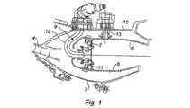
本発明のインジェクタを適用することができるガスタービンエンジンの燃焼室1は、環状であって、知られているとおり、エンジンの軸に沿って円筒形である外側ケース2と内側ケース3との間に取り付けられる。すなわち、ケース2および3によって環状の空間が形成され、この環状の空間の上流側(ガスの流れを基準にする)が、圧縮機(図示せず)の最終段に通じるディフューザ4へと開いている。燃焼室の下流側は、燃焼室において加熱されたガスを受け取る第1のタービン段(図示せず)へと開いている。燃焼室は、一体に形成されてケースの部材の適切なフランジによって支持されるシェルリングの形態で、外壁5および内壁6で作られている。上流側において、燃焼室は、燃焼室内のガスの流れに対して横方向である燃焼室端壁7によって画定されている。この壁7には、燃料および一次燃焼空気が現れる、円形の軸方向の開口が設けられている。この空気および燃料の一部が、円形の開口のうちの1つへとそれぞれ開いている混合装置8において混合される。これらの混合装置は、ディフューザ4からの空気流を案内するカウリング9に収容されている。混合装置は、通常は、空気を導入し、回転させて乱流にする軸方向または径方向の渦発生器を備える。燃料は、この時点で、それぞれの混合装置において、燃料を微細な液滴へと霧化する燃料インジェクタ10によって乱流へと注入される。これらの液滴が、渦発生器を通って届けられる空気によって混合および気化させられ、生成された混合物が、燃焼室へと導入される。図示の例では、燃焼室の端部が、デフレクタ11を有するさらなるオリフィスを備える。径方向の点火プラグ13が、開口を通じてケース2に固定されており、その端部が燃焼室の外壁5と同一面にあることを、見て取ることができる。点火プラグは、その境界が燃料噴射コーンによって描かれる空気/燃料混合物に点火するように、燃焼室の端部から所定の軸方向の距離にある。 The combustion chamber 1 of a gas turbine engine to which the injector of the present invention can be applied is annular and, as is known, between an outer case 2 and an inner case 3 that are cylindrical along the axis of the engine. Attached to. That is, an annular space is formed by the cases 2 and 3, and the upstream side of this annular space (based on the gas flow) opens to the diffuser 4 that leads to the final stage of the compressor (not shown). Yes. The downstream side of the combustion chamber is open to a first turbine stage (not shown) that receives the gas heated in the combustion chamber. The combustion chamber is made of an outer wall 5 and an inner wall 6 in the form of a shell ring that is integrally formed and supported by a suitable flange of the case member. On the upstream side, the combustion chamber is defined by a combustion chamber end wall 7 which is transverse to the gas flow in the combustion chamber. This wall 7 is provided with a circular axial opening through which fuel and primary combustion air appear. A portion of this air and fuel is mixed in a mixing device 8 that is open to one of the circular openings. These mixing devices are accommodated in a cowling 9 that guides the air flow from the diffuser 4. Mixing devices typically include an axial or radial vortex generator that introduces air and rotates it into turbulent flow. At this point, the fuel is injected into the turbulent flow by the
本発明は、アイドリング燃焼ゾーンの生成および点火の条件の生成によって、アイドリング速度における汚染物質の排出を少なくすることを目的とする。 The present invention seeks to reduce pollutant emissions at idle speeds by creating an idle combustion zone and creating ignition conditions.
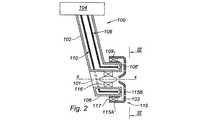
図2が、本発明によるインジェクタの例を示している。 FIG. 2 shows an example of an injector according to the invention.
インジェクタ100は、取り付け板104へと取り付けられた筒状部102を備え、取り付け板104を介して、燃焼室の適切な支持部へと固定される。筒状部は、環状の形状であって横断壁106’によって閉じられている燃料分配器形成部106によって延長されている。この分配器106の軸XXに一致する線に沿って、燃料が燃焼室へと注入される。第1の燃料供給ライン108および第2の燃料供給ライン110がそれぞれ、インジェクタ内に収容され、取り付けプレート104を通じて適切な供給回路に連絡している。ライン108および110は、分配器106を通過している。ラインはそれぞれ、マニホールド109および110へと供給を行っている。マニホールドは、分配器106の横断壁106’にそれぞれ形成されたオリフィス112および113によって、下流側方向に開いている。オリフィスは、それぞれのラインのそれぞれの流量に応じて寸法付けられている。 The
環状の分配器は、上流側および下流側に開いている軸XXの円筒形の中央ダクト101を形成している。この一次空気ダクト101が、軸方向の流れ渦発生器116を備え、流れ渦発生器116は、径方向のフィンからなり、上流側の開口を介してこのダクトに進入した一次空気を、軸を中心として回転させる。 The annular distributor forms a cylindrical
予混合構成部品115が、分配器106に取り付けられている。この構成部品115は、軸XXの分配器106の円筒部分とともに、環状の二次空気ダクト103を画定しているスリーブ状の部品115Aを備える。このダクトは、上流側に開いており、径方向のフィンからなる渦発生器117を備える。この渦発生器の目的は、そこを通過する空気の流れに、軸XXを中心とする回転運動を持たせることにある。スリーブ115Aの下流側の端部は、軸XXに直交するプレート115Bによって閉じられている。このプレートは、分配器の横断壁106’から離間している。このプレートは、リムを有する中央開口115B1を備え、リムは、その軸がXXである円錐台形状の案内面115Cを形成する。プレート115Bは、壁106’から所定の距離だけ離れており、予混合オリフィス115B2、115B3、115B4、および115B5を備える。 A
予混合オリフィスは、注入オリフィス112および113に関連付けて配置されている。 The premix orifice is located in association with the
図3の図に相当する例では、インジェクタが、n1=4個のアイドル燃料注入オリフィス112、およびn2=8個の主燃料注入オリフィス113を備える。オリフィスは、必要とされる流量に応じて寸法付けられている。さらに、オリフィスの数は、インジェクタの直径Dに応じて選択されている。総数は、いかなる機械的完全性の問題も呈することなく、最大18個とすることができる。 In the example corresponding to the diagram of FIG. 3, the injector comprises n1 = 4 idle
例えば、アイドリングオリフィス112は、0.5mm〜0.8mmの範囲の直径φi1を有し、主燃料注入オリフィス113は、0.8mm〜1.3mmの範囲の直径φi2を有する。インジェクタの直径Dは、これらのオリフィスの満足できる環状の分布を可能にするように選択されている。例えば、Dは、50mm〜70mm程度である。For example, the idling
プレート115Bの予混合オリフィス115B2、115B3、115B4、および115B5は、オリフィス112および113によって形成されるリングの径方向各側に位置する2つのリングを形成している。これらの備混合オリフィス115B2、115B3、115B4、および115B5の直径φpは、オリフィス112および113の直径に応じて決定される。Premix orifices 115B2, 115B3, 115B4, and 115B5 of plate 115B form two rings located on each radial side of the ring formed by
ここで検討している例では、アイドリング予混合オリフィスの直径φp1が、1mm〜1.5mmの範囲にある一方で、主燃料混合オリフィスの直径φp2が、2mm〜3mmの範囲にある。In the example considered here, the diameter φp1 of the idling premixing orifice is in the range of 1 mm to 1.5 mm, while the diameter φp2 of the main fuel mixing orifice is in the range of2 mm to 3 mm.
この多点式の予混合インジェクタの動作原理を、図4を参照して以下で説明する。 The operating principle of this multipoint premixing injector will be described below with reference to FIG.
オリフィス112または113を通って注入される燃料が、2つの予混合オリフィス(115B2および115B4)または(115B3および115B5)の間のプレート115Bに衝突する。この例では2mm〜4mm程度である、壁106’とプレート115Bとの間の空間が、一方の側ではダクト101からの一次空気によって掃引され、他方の側ではダクト103からの二次空気によって掃引される。予混合オリフィスに向かって膜の形態で径方向に広がる燃料が、これらのオリフィスを通過して逃げ出す空気によって運ばれる。その結果、気化が生じて空気/燃料混合物が形成される。プレートの下流側において、混合物が方向XXに運ばれ、燃焼が行われる。直径および流量は、混合物が、予混合オリフィス内での点火を防止する速度および局所的濃度を有するように決定される。 Fuel injected through
燃料の気化を改善するために、流れを乱す要素を、壁106’および115Bに組み込むことができる。さらに、燃料が、インジェクタの寿命に有利である冷却機能を果たす。 To improve fuel vaporization, flow disrupting elements can be incorporated into the walls 106 'and 115B. In addition, the fuel performs a cooling function that is beneficial to the life of the injector.
図2に見て取ることができるように、一次ダクト101からの空気の一部が、予混合の空間へと案内され、残りは、中央オリフィス115B1を通って逃げ出し、プレート115Bの外側部分にアンチコーキング空気の膜を形成する。 As can be seen in FIG. 2, a portion of the air from the
さらに、一次空気および二次空気を、軸XXを中心として同じ方向に回転させても、あるいは反対方向に回転させてもよいことを、見て取ることができる。また、それらが接線方向の成分を有さなくてもよい。 Furthermore, it can be seen that the primary air and the secondary air may be rotated in the same direction about the axis XX or in opposite directions. Moreover, they do not have to have a tangential component.
この構成の1つの重要な利点は、気化させた混合物に外壁に位置する点火プラグによって容易に点火を行うことができる燃焼室の外側に向かって位置する、アイドル燃焼領域を生成できる点にある。気化混合物の点火がインジェクタにおいて生じるとき、気化領域が環状であるために、火炎が他のインジェクタへと容易に広がる。 One important advantage of this configuration is that it can create an idle combustion region located towards the outside of the combustion chamber where the vaporized mixture can be easily ignited by a spark plug located on the outer wall. When ignition of the vapor mixture occurs in the injector, the flame is easily spread to other injectors because the vaporization region is annular.
主回路の点火も、インジェクタに属する対応する回路に燃料が供給されるとすぐに、火炎の伝搬によって生じる。 The ignition of the main circuit also occurs by flame propagation as soon as fuel is supplied to the corresponding circuit belonging to the injector.
2つの回路の間で、動作は以下のとおりである。 The operation between the two circuits is as follows.
軽い負荷においては、アイドリング回路のみが点火される。 At light loads, only the idling circuit is ignited.
全開までの中間の速度においては、両方の回路に燃料が供給され、燃焼が燃焼室の全体にわたって径方向に広がる。主回路およびアイドリング回路の燃料送出の割合は、現実には、0.7から1.2の範囲である。このように、この段階的な燃焼は、アイドリング燃焼領域からの排出物の低減を促進する。 At intermediate speeds until full open, fuel is supplied to both circuits and combustion spreads radially across the combustion chamber. The rate of fuel delivery in the main circuit and idling circuit is actually in the range of 0.7 to 1.2. Thus, this staged combustion facilitates the reduction of emissions from the idling combustion region.
全開においては、2つの回路の流量間の比が1.8から2.2である。これは、煙および汚染のもとであるNOxの形成を少なくする。 In full open, the ratio between the flow rates of the two circuits is 1.8 to 2.2. This reduces the formation of NOx, which is a source of smoke and contamination.
そのコンパクトな構造ゆえ、大きな変更を行う必要なく、燃焼室に燃料を供給する既存の装置へと、このインジェクタを容易に組み込むことができる。 Because of its compact structure, the injector can be easily incorporated into existing equipment that supplies fuel to the combustion chamber without the need for major changes.
3 ケース
4 ディフューザ
5 外壁
6 内壁
7 燃焼室の端壁
9 カウリング
10 燃料インジェクタ
11 デフレクタ
13 点火プラグ
100 インジェクタ
101 一次空気ダクト
102 筒状部
103 二次空気ダクト
104 取り付け板
106 分配器
106’ 横断壁
108、110 燃料供給ライン
109 マニホールド
112、113 オリフィス
115 予混合部
115A スリーブ
115B プレート
115B1 中央開口
115B2、115B3、115B4、115B5 予混合オリフィス
116、117 渦発生器DESCRIPTION OF SYMBOLS 3 Case 4 Diffuser 5 Outer wall 6 Inner wall 7 End wall of combustion chamber 9
Claims (11)
Translated fromJapanese前記燃料インジェクタの各々が、アイドル速度での運転のための第1の燃料供給ラインと、全開までの速度での運転のための第2の主たる燃料供給ラインとを備え、2つの燃料供給ラインが、アイドル用の第1の注入オリフィスおよび第2の主たる注入オリフィスにそれぞれ連絡しており、
各燃料インジェクタは、n1個の第1の注入オリフィスおよびn2個の第2の注入オリフィスを、n1/n2<1なる比にて備え、第1および第2の注入オリフィスが、リング状に配置され、第1の注入オリフィスが、該リングの1つのセクタを占め、燃料インジェクタの該セクタが、径方向外側に位置している、前記ガスタービンエンジン。A gas turbine engine having an annular combustion chamber and having a plurality of fuel injectors distributed about the axis of the combustion chamber,
Each of the fuel injectors comprises a first fuel supply line for operation at idle speed and a second main fuel supply line for operation at speed up to full open, two fuel supply lines Each communicating with a first injection orifice and a second main injection orifice for idle,
Each fuel injector includes n1 first injection orifices and n2 second injection orifices in a ratio of n1 / n2 <1, and the first and second injection orifices are arranged in a ringshape. , first injection orifices occupy one sector ofthering, the sectors of the fuel injector is located radially outwardly, the gas turbine engine.
Applications Claiming Priority (2)
| Application Number | Priority Date | Filing Date | Title |
|---|---|---|---|
| FR0654137 | 2006-10-06 | ||
| FR0654137AFR2906868B1 (en) | 2006-10-06 | 2006-10-06 | FUEL INJECTOR FOR GAS TURBINE ENGINE COMBUSTION CHAMBER |
Publications (2)
| Publication Number | Publication Date |
|---|---|
| JP2008096100A JP2008096100A (en) | 2008-04-24 |
| JP4930921B2true JP4930921B2 (en) | 2012-05-16 |
Family
ID=38456456
Family Applications (1)
| Application Number | Title | Priority Date | Filing Date |
|---|---|---|---|
| JP2007259471AExpired - Fee RelatedJP4930921B2 (en) | 2006-10-06 | 2007-10-03 | Fuel injector for combustion chamber of gas turbine engine |
Country Status (6)
| Country | Link |
|---|---|
| US (1) | US7849693B2 (en) |
| EP (1) | EP1909031B1 (en) |
| JP (1) | JP4930921B2 (en) |
| CA (1) | CA2605952C (en) |
| FR (1) | FR2906868B1 (en) |
| RU (1) | RU2433348C2 (en) |
Families Citing this family (16)
| Publication number | Priority date | Publication date | Assignee | Title |
|---|---|---|---|---|
| JP5147938B2 (en)* | 2007-07-02 | 2013-02-20 | シーメンス アクチエンゲゼルシヤフト | Burner and burner operation method |
| US20110072823A1 (en)* | 2009-09-30 | 2011-03-31 | Daih-Yeou Chen | Gas turbine engine fuel injector |
| US9194297B2 (en) | 2010-12-08 | 2015-11-24 | Parker-Hannifin Corporation | Multiple circuit fuel manifold |
| US9958093B2 (en) | 2010-12-08 | 2018-05-01 | Parker-Hannifin Corporation | Flexible hose assembly with multiple flow passages |
| US10317081B2 (en)* | 2011-01-26 | 2019-06-11 | United Technologies Corporation | Fuel injector assembly |
| JP5653774B2 (en)* | 2011-01-27 | 2015-01-14 | 三菱重工業株式会社 | Gas turbine combustor |
| FR2971039B1 (en)* | 2011-02-02 | 2013-01-11 | Turbomeca | GAS TURBINE FUEL COMBUSTION CHAMBER INJECTOR WITH DOUBLE FUEL CIRCUIT AND COMBUSTION CHAMBER EQUIPPED WITH AT LEAST ONE SUCH INJECTOR |
| US9181876B2 (en)* | 2012-01-04 | 2015-11-10 | General Electric Company | Method and apparatus for operating a gas turbine engine |
| US9772054B2 (en) | 2013-03-15 | 2017-09-26 | Parker-Hannifin Corporation | Concentric flexible hose assembly |
| FR3047557B1 (en)* | 2016-02-05 | 2019-10-11 | Bayern-Chemie Gesellschaft Fur Flugchemische Antriebe Mbh | DEVICE AND SYSTEM FOR CONTROLLING MISSILES AND "KILL VEHICLES" USED WITH FUEL IN THE FORM OF GEL |
| DE102017201771A1 (en) | 2017-02-03 | 2018-08-09 | Siemens Aktiengesellschaft | Circumferential grading concept for a burner assembly |
| US10823419B2 (en)* | 2018-03-01 | 2020-11-03 | General Electric Company | Combustion system with deflector |
| US10816213B2 (en)* | 2018-03-01 | 2020-10-27 | General Electric Company | Combustor assembly with structural cowl and decoupled chamber |
| US11156164B2 (en) | 2019-05-21 | 2021-10-26 | General Electric Company | System and method for high frequency accoustic dampers with caps |
| US11174792B2 (en) | 2019-05-21 | 2021-11-16 | General Electric Company | System and method for high frequency acoustic dampers with baffles |
| US12130016B1 (en) | 2023-05-31 | 2024-10-29 | General Electric Company | Turbine engine including a combustor |
Family Cites Families (16)
| Publication number | Priority date | Publication date | Assignee | Title |
|---|---|---|---|---|
| GB774704A (en)* | 1952-05-07 | 1957-05-15 | Rolls Royce | Improvements relating to combustion equipment for gas-turbine engines |
| GB824306A (en)* | 1956-04-25 | 1959-11-25 | Rolls Royce | Improvements in or relating to combustion equipment of gas-turbine engines |
| US3763650A (en)* | 1971-07-26 | 1973-10-09 | Westinghouse Electric Corp | Gas turbine temperature profiling structure |
| GB2084903B (en)* | 1980-10-13 | 1984-05-31 | Central Electr Generat Board | Atomising liquid fuel |
| US4720970A (en)* | 1982-11-05 | 1988-01-26 | The United States Of America As Represented By The Secretary Of The Air Force | Sector airflow variable geometry combustor |
| JPH0668374B2 (en)* | 1987-07-28 | 1994-08-31 | 石川島播磨重工業株式会社 | Fuel injector |
| JPS6433421U (en) | 1987-08-24 | 1989-03-01 | ||
| FR2695713B1 (en)* | 1992-09-17 | 1994-10-21 | Snecma | Aerodynamic premix injection system. |
| JP3069347B1 (en)* | 1999-06-11 | 2000-07-24 | 川崎重工業株式会社 | Burner device for gas turbine combustor |
| JP2002038970A (en)* | 2000-07-25 | 2002-02-06 | Hitachi Ltd | Gas turbine combustor |
| EP1199523A1 (en)* | 2000-10-20 | 2002-04-24 | Siemens Aktiengesellschaft | Method of firing burners in a combustion chamber and combustion chamber with a number of burners |
| EP1278014B1 (en)* | 2001-07-18 | 2007-01-24 | Rolls-Royce PLC | Fuel delivery system |
| JP4453675B2 (en)* | 2001-08-29 | 2010-04-21 | 株式会社日立製作所 | Combustor and method of operating the combustor |
| DE10160997A1 (en)* | 2001-12-12 | 2003-07-03 | Rolls Royce Deutschland | Lean premix burner for a gas turbine and method for operating a lean premix burner |
| US6886342B2 (en)* | 2002-12-17 | 2005-05-03 | Pratt & Whitney Canada Corp. | Vortex fuel nozzle to reduce noise levels and improve mixing |
| JP4015656B2 (en)* | 2004-11-17 | 2007-11-28 | 三菱重工業株式会社 | Gas turbine combustor |
- 2006
- 2006-10-06FRFR0654137Apatent/FR2906868B1/enactiveActive
- 2007
- 2007-10-01EPEP07117658.0Apatent/EP1909031B1/enactiveActive
- 2007-10-03JPJP2007259471Apatent/JP4930921B2/ennot_activeExpired - Fee Related
- 2007-10-05USUS11/868,176patent/US7849693B2/enactiveActive
- 2007-10-05RURU2007137046/06Apatent/RU2433348C2/ennot_activeIP Right Cessation
- 2007-10-05CACA2605952Apatent/CA2605952C/ennot_activeExpired - Fee Related
Also Published As
| Publication number | Publication date |
|---|---|
| EP1909031B1 (en) | 2017-02-08 |
| FR2906868A1 (en) | 2008-04-11 |
| FR2906868B1 (en) | 2011-11-18 |
| US20080083841A1 (en) | 2008-04-10 |
| CA2605952A1 (en) | 2008-04-06 |
| JP2008096100A (en) | 2008-04-24 |
| RU2433348C2 (en) | 2011-11-10 |
| CA2605952C (en) | 2015-04-07 |
| EP1909031A1 (en) | 2008-04-09 |
| US7849693B2 (en) | 2010-12-14 |
| RU2007137046A (en) | 2009-04-10 |
Similar Documents
| Publication | Publication Date | Title |
|---|---|---|
| JP4930921B2 (en) | Fuel injector for combustion chamber of gas turbine engine | |
| CN103542427B (en) | Gas turbine combustion system | |
| US7891190B2 (en) | Combustion chamber of a turbomachine | |
| JP4162430B2 (en) | Method of operating gas turbine engine, combustor and mixer assembly | |
| JP4958709B2 (en) | Device for reducing combustor acoustics | |
| US5156002A (en) | Low emissions gas turbine combustor | |
| JP2928125B2 (en) | Method of operating a gas turbine device and method of reducing combustion instability in a low NOx gas turbine device | |
| US8959921B2 (en) | Flame tolerant secondary fuel nozzle | |
| JP4162429B2 (en) | Method of operating gas turbine engine, combustor and mixer assembly | |
| JP4658471B2 (en) | Method and apparatus for reducing combustor emissions in a gas turbine engine | |
| JP5930731B2 (en) | Combustor for gas turbine engine and method for operating gas turbine engine combustor | |
| US20100170253A1 (en) | Method and apparatus for fuel injection in a turbine engine | |
| US20100263382A1 (en) | Dual orifice pilot fuel injector | |
| US20050044854A1 (en) | Air/fuel injection system having cold plasma generating means | |
| JP2002115847A (en) | Multiple annular combustion chamber swirler having spray pilot | |
| JP2011027402A (en) | Fuel injection device in turbine engine | |
| JPH06257751A (en) | Gas turbine combustion apparatus and inhibiting method of combustion dynamic pressure during transfer from primary operation mode to premix operation mode | |
| JP2010085083A (en) | Tubular fuel injector for secondary fuel nozzle | |
| US7024861B2 (en) | Fully premixed pilotless secondary fuel nozzle with improved tip cooling | |
| JP2024101934A (en) | Combustor suitable for hydrogen gas turbine, and combustion nozzle thereof | |
| US12339005B2 (en) | Hydrogen fuel distributor | |
| US20250027649A1 (en) | Staged blade injector | |
| US20240263786A1 (en) | Central air passage with radial fuel distributor | |
| JP2024080498A (en) | Combustor and combustion nozzle suitable for hydrogen gas turbine | |
| JP2025101930A (en) | Combustor and combustion nozzle suitable for hydrogen gas turbine |
Legal Events
| Date | Code | Title | Description |
|---|---|---|---|
| A621 | Written request for application examination | Free format text:JAPANESE INTERMEDIATE CODE: A621 Effective date:20091023 | |
| A131 | Notification of reasons for refusal | Free format text:JAPANESE INTERMEDIATE CODE: A131 Effective date:20110215 | |
| A601 | Written request for extension of time | Free format text:JAPANESE INTERMEDIATE CODE: A601 Effective date:20110509 | |
| A602 | Written permission of extension of time | Free format text:JAPANESE INTERMEDIATE CODE: A602 Effective date:20110512 | |
| A521 | Request for written amendment filed | Free format text:JAPANESE INTERMEDIATE CODE: A523 Effective date:20110811 | |
| TRDD | Decision of grant or rejection written | ||
| A01 | Written decision to grant a patent or to grant a registration (utility model) | Free format text:JAPANESE INTERMEDIATE CODE: A01 Effective date:20120117 | |
| A01 | Written decision to grant a patent or to grant a registration (utility model) | Free format text:JAPANESE INTERMEDIATE CODE: A01 | |
| A61 | First payment of annual fees (during grant procedure) | Free format text:JAPANESE INTERMEDIATE CODE: A61 Effective date:20120206 | |
| R150 | Certificate of patent or registration of utility model | Free format text:JAPANESE INTERMEDIATE CODE: R150 | |
| FPAY | Renewal fee payment (event date is renewal date of database) | Free format text:PAYMENT UNTIL: 20150224 Year of fee payment:3 | |
| R250 | Receipt of annual fees | Free format text:JAPANESE INTERMEDIATE CODE: R250 | |
| R250 | Receipt of annual fees | Free format text:JAPANESE INTERMEDIATE CODE: R250 | |
| LAPS | Cancellation because of no payment of annual fees |