JP4930275B2 - Communication system, communication method, transmitter, receiver, rate calculation method, and program - Google Patents
Communication system, communication method, transmitter, receiver, rate calculation method, and programDownload PDFInfo
- Publication number
- JP4930275B2 JP4930275B2JP2007214498AJP2007214498AJP4930275B2JP 4930275 B2JP4930275 B2JP 4930275B2JP 2007214498 AJP2007214498 AJP 2007214498AJP 2007214498 AJP2007214498 AJP 2007214498AJP 4930275 B2JP4930275 B2JP 4930275B2
- Authority
- JP
- Japan
- Prior art keywords
- rtt
- network
- ack
- transmission
- packet
- Prior art date
- Legal status (The legal status is an assumption and is not a legal conclusion. Google has not performed a legal analysis and makes no representation as to the accuracy of the status listed.)
- Active
Links
- 238000004364calculation methodMethods0.000titleclaimsdescription77
- 238000004891communicationMethods0.000titleclaimsdescription48
- 238000000034methodMethods0.000titleclaimsdescription23
- 230000005540biological transmissionEffects0.000claimsdescription218
- 239000000872bufferSubstances0.000claimsdescription125
- 238000012217deletionMethods0.000claimsdescription9
- 230000037430deletionEffects0.000claimsdescription9
- 238000000605extractionMethods0.000claimsdescription9
- 230000001960triggered effectEffects0.000claimsdescription5
- 238000012544monitoring processMethods0.000claims1
- 238000012545processingMethods0.000description18
- 238000012790confirmationMethods0.000description16
- 238000012546transferMethods0.000description14
- 238000007726management methodMethods0.000description7
- 230000003287optical effectEffects0.000description7
- 230000000694effectsEffects0.000description6
- 230000004044responseEffects0.000description4
- 241001522296Erithacus rubeculaSpecies0.000description3
- 238000010586diagramMethods0.000description3
- 230000008569processEffects0.000description3
- 230000003247decreasing effectEffects0.000description2
- 239000000284extractSubstances0.000description2
- 230000007246mechanismEffects0.000description2
- 230000009467reductionEffects0.000description2
- 230000000903blocking effectEffects0.000description1
- 239000012464large bufferSubstances0.000description1
- 238000005259measurementMethods0.000description1
- 238000012986modificationMethods0.000description1
- 230000004048modificationEffects0.000description1
- 230000007480spreadingEffects0.000description1
Images


Landscapes
- Data Exchanges In Wide-Area Networks (AREA)
Description
Translated fromJapanese本発明は、複数経路にデータを分散させて帯域拡大を図る通信技術に関し、特に送信機と受信機が複数の網によって接続されているマルチパス環境において、1段のみのレート管理で、遅延ベースのレート制御を行うための通信システム、通信方法、送信機、受信機、レート計算方法およびプログラムに関する。 The present invention relates to a communication technique for spreading data by distributing data in a plurality of paths, and in particular, in a multipath environment in which a transmitter and a receiver are connected by a plurality of networks, with only one-stage rate management and a delay base. The present invention relates to a communication system, a communication method, a transmitter, a receiver, a rate calculation method, and a program for performing rate control.
従来、キューイング遅延を小さくし、転送レイテンシを小さくする輻輳制御方法として、遅延ベースのレート制御がある(たとえば、特許文献1)。この方法では、ある網における直近に測定した往復遅延時間(RTT)と、これまでに測定した最小往復遅延時間(RTTmin)との差分により、キューイング遅延時間を算出し、このキューイング遅延時間が最小となるように、送信レートの増加及び減少を制御する。 Conventionally, there is delay-based rate control as a congestion control method that reduces queuing delay and transfer latency (for example, Patent Document 1). In this method, the queuing delay time is calculated from the difference between the most recently measured round-trip delay time (RTT) and the minimum round-trip delay time (RTTmin) measured so far. Control the increase and decrease of the transmission rate to minimize.
また従来、送信端末と受信端末の間の通信で用いられる1つの通信フローのデータを複数のフローに分岐させ、元のフローを復元する通信方法がある。このような通信方法として、例えば送信端末が属する第1のLAN(Local Area Network)と受信端末が属する第2のLANに、それぞれゲートウェイを設置し、送信端末から送出されたTCP(Transmission Control Protocol)コネクションのデータを、第1のLANのゲートウェイにおいてパケット単位でそれぞれの通信経路に振り分け、第2のLANのゲートウェイでは複数の通信経路から受信したパケットの順序逆転をTCPのシーケンス番号に従って補正してデータを復元する方法が提案されている(たとえば、特許文献2参照)。 Conventionally, there is a communication method in which data of one communication flow used in communication between a transmission terminal and a reception terminal is branched into a plurality of flows to restore the original flow. As such a communication method, for example, a TCP (Transmission Control Protocol) transmitted from a transmission terminal is installed in a gateway in each of a first LAN (Local Area Network) to which a transmission terminal belongs and a second LAN to which a reception terminal belongs. The connection data is distributed to each communication path in packet units in the first LAN gateway, and the second LAN gateway corrects the order reversal of packets received from a plurality of communication paths according to the TCP sequence number. Has been proposed (see, for example, Patent Document 2).
また従来、複数の通信回線を効率的に利用し、回線利用率を向上させる方法として、端末のTCPに機能を追加して、従来1本のTCPコネクションを用いていた通信を複数のTCPコネクションを利用するように変更する方法がある(例えば、特許文献3参照)。この方法では、送信端末と受信端末間の通信で1つの通信フローで行われていた通信を、複数の通信フローに分割して並列的に送る。送信端末から受信端末へとデータを送信する場合、送信端末の通信プロトコルは、1つの通信フローのデータを分割して複数の通信フローに振り分け、分割した複数の通信フローを元の1つの通信フローに復元するための復元情報として新たなヘッダをTCP/IPパケットに付加して(つまり2系統のシーケンス番号を用いて)、複数の通信フローでデータを送信する。受信端末の通信プロトコルは、複数の通信フローから受信したデータの復元情報を参照し、1つの通信フローを復元する。 Conventionally, as a method for efficiently using a plurality of communication lines and improving the line utilization rate, a function has been added to the TCP of the terminal, and a communication that has conventionally used one TCP connection is changed to a plurality of TCP connections. There is a method of changing to use (see, for example, Patent Document 3). In this method, communication performed in one communication flow in communication between the transmission terminal and the reception terminal is divided into a plurality of communication flows and sent in parallel. When data is transmitted from the transmission terminal to the reception terminal, the communication protocol of the transmission terminal divides the data of one communication flow and distributes it to a plurality of communication flows, and the plurality of divided communication flows are one original communication flow. A new header is added to the TCP / IP packet as restoration information for restoration to (i.e., using two system sequence numbers), and data is transmitted in a plurality of communication flows. The communication protocol of the receiving terminal refers to the restoration information of data received from a plurality of communication flows, and restores one communication flow.
第1の課題として、帯域を有効利用できないという問題があった。 As a first problem, there is a problem that the bandwidth cannot be effectively used.
従来技術1のレート制御方法は、ある一定の最小往復遅延時間(RTTmin)を有する1つの通信経路において使用されることを前提として、直近に測定したRTTと過去に測定したRTTminとの差分によりレート計算を行うように設計されている。これと従来技術2のようなゲートウェイを組み合わせて、複数の通信経路を用いた通信を行うと、通信経路ごとの最小往復遅延時間に差がある場合に、キューイング遅延を大きく見積もってしまい、送信レート(帯域)を大幅に制限してしまう。つまり、常に混雑が発生していると誤認識し、送信速度を大幅に低下させるため、帯域を有効利用できない。 The rate control method of the prior art 1 is based on the difference between the most recently measured RTT and the previously measured RTTmin on the assumption that it is used in one communication path having a certain minimum round trip delay time (RTTmin). Designed to do calculations. When this is combined with a gateway like the prior art 2 and communication using a plurality of communication paths is performed, if there is a difference in the minimum round-trip delay time for each communication path, the queuing delay is greatly estimated, and transmission is performed. The rate (bandwidth) is greatly limited. In other words, the band cannot be effectively used because it is erroneously recognized that congestion is always occurring and the transmission speed is greatly reduced.
たとえば図6に示すように、網31〜34の最小往復遅延時間(RTTmin)が、それぞれ150ms、200ms、100ms、180msと異なる値である場合、従来技術1と従来技術2を単純に組み合わせて利用すると、従来技術1のレート制御機構は、網毎にRTTminを保持することができないため、RTTminは100msであると認識する。この結果、網31における最新の測定RTTが150msであった場合、つまり、網31に全く混雑が発生していない場合でも、50msのキューイング遅延すなわち混雑が発生しているとみなし、キューイング遅延が0になるまで送信レートを低下させる。図6の例では、網32および網34においても同様に、混雑が発生していないにもかかわらず、混雑が発生していると誤認識し、大幅にレートを低下させる。 For example, as shown in FIG. 6, when the minimum round-trip delay time (RTTmin) of the networks 31 to 34 is different from 150 ms, 200 ms, 100 ms, and 180 ms, respectively, the prior art 1 and the prior art 2 are used in a simple combination. Then, since the rate control mechanism of the prior art 1 cannot hold RTTmin for each network, it recognizes that RTTmin is 100 ms. As a result, even when the latest measured RTT in the network 31 is 150 ms, that is, when no congestion occurs in the network 31, it is considered that a queuing delay of 50 ms, that is, congestion occurs, and the queuing delay The transmission rate is decreased until becomes zero. In the example of FIG. 6, similarly in the network 32 and the
第2の課題として、網毎(複数系統)のレート管理を行うと、大きなバッファを必要するにも関わらず、性能を得られないという問題があった。 As a second problem, when rate management for each network (a plurality of systems) is performed, there is a problem that performance cannot be obtained even though a large buffer is required.
従来技術1と従来技術3を組合せて、網毎に細かくレート計算を行うことで、第1の課題を回避することもできる。しかしながら、従来技術1と従来技術3を組合せた場合、レート計算処理、転送処理ならびに管理機構などが複雑化し、コスト増を招くという問題があった。 The first problem can be avoided by combining the prior art 1 and the prior art 3 and performing rate calculation finely for each network. However, when the related art 1 and the related art 3 are combined, there is a problem that the rate calculation processing, the transfer processing, the management mechanism, and the like are complicated and the cost is increased.
さらに、従来技術1と従来技術3を組合せて、網毎に細かくレート計算を行った場合において、端末に対する順序保証を行う場合は、受信側において、高速な網を経由して先に到着したパケットが、最も低速な網を経由してあとから到着するパケットを待つ必要がある(ヘッドオブラインブロッキング=HOL問題)。したがって、高速なリンクに大量のパケットを送っても、低速なリンクの速度に影響されてしまい、速度が出ないばかりでなく、受信側で高速リンクを経由したパケットを保存しておくために、大量のバッファが必要となる。 Further, when the rate calculation is performed finely for each network by combining the prior art 1 and the prior art 3, when the order is guaranteed for the terminal, the packet that arrives first via the high-speed network on the receiving side However, it is necessary to wait for a packet that arrives later via the slowest network (head-of-line blocking = HOL problem). Therefore, even if a large number of packets are sent to the high-speed link, it is affected by the speed of the low-speed link, and not only the speed does not come out, but also in order to save the packet via the high-speed link on the receiving side, A large amount of buffer is required.
本発明の目的は、送信機と受信機が複数の網によって接続されているマルチパス環境において、1系統のみのレート管理で、受信側のバッファを極力小さく抑えながら、遅延ベースのレート制御を行うための通信システム、通信方法、送信機、受信機、レート計算方法およびプログラムを提供することにある。 It is an object of the present invention to perform delay-based rate control while minimizing the reception-side buffer by managing the rate of only one system in a multipath environment in which a transmitter and a receiver are connected by a plurality of networks. A communication system, a communication method, a transmitter, a receiver, a rate calculation method, and a program are provided.
本発明の第1の通信システムは、送信機と受信機とが複数の網で接続された通信システムであって、前記受信機は、ACKの送信契機となったパケットを受信した網に、折り返しACKを送信するACK送信部を備え、前記送信機は、ACKをもとにRTT、最小RTTを計算する、網ごとに設置された複数のRTT計算部と、各網ごとの最新測定RTTと、各網ごとの最小RTTとの差により網の混雑を推定し、レート制御を行うレート計算部とを備える。 A first communication system of the present invention is a communication system in which a transmitter and a receiver are connected by a plurality of networks, and the receiver loops back to a network that has received a packet that triggers transmission of an ACK. An ACK transmitter for transmitting ACK, and the transmitter calculates RTT and minimum RTT based on ACK, a plurality of RTT calculators installed for each network, a latest measurement RTT for each network, And a rate calculation unit that estimates network congestion based on a difference from the minimum RTT for each network and performs rate control.
本発明の第1の通信方法は、送信機と受信機とが複数の網で接続された通信システムにおける通信方法であって、前記受信機が、ACKの送信契機となったパケットを受信した網に、折り返しACKを送信し、前記送信機が、ACKをもとにRTT、最小RTTを計算し、前記送信機が、各網ごとの最新測定RTTと、各網ごとの最小RTTとの差により網の混雑を推定し、レート制御を行う。 A first communication method of the present invention is a communication method in a communication system in which a transmitter and a receiver are connected by a plurality of networks, and the receiver receives a packet that triggers transmission of an ACK. And the transmitter calculates the RTT and the minimum RTT based on the ACK, and the transmitter calculates the difference between the latest measured RTT for each network and the minimum RTT for each network. Estimate network congestion and perform rate control.
本発明の第1の送信機は、ACKの送信契機となったパケットを受信した網に折り返しACKを送信する受信機と複数の網で接続された送信機であって、受信したACKをもとにRTT、最小RTTを計算する、網ごとに設置された複数のRTT計算部と、各網ごとの最新測定RTTと、各網ごとの最小RTTとの差により網の混雑を推定し、レート制御を行うレート計算部とを備える。 A first transmitter of the present invention is a transmitter connected by a plurality of networks to a receiver that transmits a loopback ACK to a network that has received a packet that triggers transmission of an ACK, and is based on the received ACK. RTT and minimum RTT are calculated in each network, the congestion of the network is estimated by the difference between a plurality of RTT calculation units installed for each network, the latest measured RTT for each network, and the minimum RTT for each network, and rate control A rate calculation unit.
本発明の第1の受信機は、送信機と複数の網で接続された受信機であって、ACKの送信契機となったパケットを受信した網に、折り返しACKを送信するACK送信部を備える。 The first receiver of the present invention is a receiver connected to a transmitter through a plurality of networks, and includes an ACK transmission unit that transmits a return ACK to a network that has received a packet that triggers transmission of an ACK. .
本発明の第1のレート計算方法は、送信機と受信機とが複数の網で接続された通信システムにおけるレート計算方法であって、前記受信機が、ACKの送信契機となったパケットを受信した網に、折り返しでACKを送信し、前記送信機が、各網ごとにACKをもとにRTT、最小RTTを計算し、前記送信機が、各網ごとの最新測定RTTと、各網ごとの最小RTTとの差により網の混雑を推定し、レート制御を行う。 A first rate calculation method of the present invention is a rate calculation method in a communication system in which a transmitter and a receiver are connected by a plurality of networks, and the receiver receives a packet that triggers transmission of an ACK. ACK is sent back to the network, and the transmitter calculates the RTT and the minimum RTT based on the ACK for each network, and the transmitter calculates the latest measured RTT for each network and each network. Network congestion is estimated based on the difference from the minimum RTT, and rate control is performed.
本発明の第1のプログラムは、ACKの送信契機となったパケットを受信した網に折り返しACKを送信する受信機と複数の網で接続された送信機を構成するコンピュータを、受信したACKをもとにRTT、最小RTTを計算する、網ごとに設置された複数のRTT計算部と、各網ごとの最新測定RTTと、各網ごとの最小RTTとの差により網の混雑を推定し、レート制御を行うレート計算部として機能させる。 The first program of the present invention is configured to store a computer that constitutes a receiver connected to a network that receives a return ACK to a network that has received a packet that triggered the transmission of the ACK and a transmitter connected by a plurality of networks with the received ACK. The network congestion is estimated by the difference between the RTT calculation unit installed for each network, the latest measured RTT for each network, and the minimum RTT for each network. It functions as a rate calculation unit that performs control.
本発明の第2のプログラムは、送信機と複数の網で接続された受信機を構成するコンピュータを、ACKの送信契機となったパケットを受信した網に、折り返しACKを送信するACK送信部として機能させる。 The second program of the present invention uses a computer that constitutes a receiver connected to a transmitter through a plurality of networks as an ACK transmission unit that transmits a return ACK to a network that has received a packet that triggered the transmission of an ACK. Make it work.
本発明によれば、送信機と受信機が複数の網によって接続されているマルチパス環境において、1段のみのレート管理で、受信側のバッファを極力小さく抑えながら、遅延ベースのレート制御を行うことができる。 According to the present invention, in a multipath environment in which a transmitter and a receiver are connected by a plurality of networks, the delay-based rate control is performed while the reception-side buffer is kept as small as possible by the single-stage rate management. be able to.
これは、受信機が、パケットが到着したPHY(網)に対して、対応するACKパケットを送出し、送信機内に、RTT、最小RTTを計算するRTT計算部を、網毎に設け、レート計算部が、各網ごとの最新RTTと過去の最小RTTとの差により網の混雑を推定し、レート制御を行うからである。 This is because the receiver sends out a corresponding ACK packet to the PHY (network) where the packet has arrived, and an RTT calculation unit for calculating the RTT and the minimum RTT is provided in each transmitter to calculate the rate. This is because the network performs rate control by estimating network congestion based on the difference between the latest RTT and the past minimum RTT for each network.
以下の説明においては、1対の送信機と受信機との間の通信を、1フローと定義する。また、あるフローが流れる経路をパスと定義する。例えば、1フローを4つの網(ネットワーク)に分散させて通信する場合は、4パスを用いて通信すると言い、2つのフローを4つの網(ネットワーク)に分散させて通信する場合は、8つのパスを用いて通信するという。ただし以下の説明では、1つのフローに着目して説明を行うため、結果的に網とパスが同義になっている。 In the following description, communication between a pair of transmitter and receiver is defined as one flow. Also, a route through which a certain flow flows is defined as a path. For example, when communicating by distributing one flow to four networks (networks), it is said that communication is performed using four paths. When communicating by distributing two flows to four networks (networks), there are eight Communicate using a path. However, in the following description, since description will be made focusing on one flow, as a result, the network and the path are synonymous.
(第1の実施の形態)
(構成の説明)
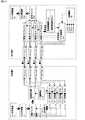
図1を参照して、本実施の形態における構成について説明する。(First embodiment)
(Description of configuration)
With reference to FIG. 1, the structure in this Embodiment is demonstrated.
送信機1は、データ送信部11、送信バッファ12、送信振分部13、PHY141〜144、RTT計算部151〜154、レート計算部16、内蔵時計19から構成される。 The transmitter 1 includes a data transmission unit 11, a
データ送信部11は、受信機2に対して送信するデータを生成し、前記データを網31〜網34で転送可能な大きさに分割し、分割した個々のデータ(以下パケットと呼ぶ)に対して転送に必要なヘッダを設定し、送信バッファ12に渡す。一般的にはサーバアプリケーションなどが、データ送信部11にあたる。 The data transmission unit 11 generates data to be transmitted to the receiver 2, divides the data into sizes that can be transferred by the networks 31 to 34, and for each divided data (hereinafter referred to as a packet). Then, a header necessary for transfer is set and passed to the
送信バッファ12は、FIFOバッファであり、以下の動作をおこなう。
(1)データ送信部11からパケットを受け取り格納する。
(2)レート計算部16が決定した速度にしたがい、前記パケットを送信振分部13に送る。The
(1) A packet is received from the data transmission unit 11 and stored.
(2) The packet is sent to the
送信振分部13は、送信バッファ12から到着したパケットを、ラウンドロビン等によりPHY141〜144に順次振り分けて転送する。この際、内蔵時計19より時刻情報を取得し、パケットのヘッダに送信時刻を埋め込む。PHYの指定は、パケットのヘッダ内に送出希望先PHYのPHY番号を記載することで行っても良い。 The
PHY141は送信振分部13からパケットを受信し、網31で伝送可能な形式(電気信号、光信号)に変換して、前記パケットを網31に送出する。また逆に、網31からパケット(ACK)を受信し、RTT計算部151に転送する。PHY141は、網との間のインタフェースであり、一般的には、フィジカルレイヤコントローラ(physical layer controller)がPHY141にあたる。 The
PHY142〜144は、網32〜34について、PHY141と同様の動作を行う。 The PHYs 142 to 144 perform the same operation as the
RTT計算部151は、PHY141からパケット(ACK)を受信し、ACKパケットのヘッダに埋め込まれている送信時刻と、内蔵時計19から取得した受信時刻とから、網31の往復遅延時間(RTT)を計算し、レート計算部16に通知する。この際、網31のRTTの最小値(最小RTT)も保持する。 The RTT calculation unit 151 receives the packet (ACK) from the
RTT計算部152〜154は、網32〜34に関して、RTT計算部151と同様の動作を行う。 The RTT calculators 152 to 154 perform the same operation as the RTT calculator 151 for the networks 32 to 34.
レート計算部16は、RTT計算部151〜154よりRTTの通知を受け、今回通知を受けたRTTと、今回通知を受けた網の最小RTTとの差より、網31〜34のキューイング遅延(すなわち混雑)を計算し、これをもとに送信バッファ12からのパケット送信レート(帯域)を決定し、送信バッファ12に通知する。 The
レート計算部16における新規レートR’は、Rを現在のレート、αを増加定数、βを減少定数、RTTをRTT計算部151〜154より通知を受けたRTT、RTTminをRTT計算部151〜154より通知を受けた最小RTT、Tcをレート計算間隔とすると、以下の式で表せる。
R’=R+(α/RTT−β×(RTT−RTTmin)×R/RTT)×Tc
…式1The new rate R ′ in the
R ′ = R + (α / RTT−β × (RTT−RTTmin) × R / RTT) × Tc
... Formula 1
式1では、現在のレートRに、どのくらいのレートを増加させるか、減少させるかを考慮して、新規レートR’を計算している。具体的には、増加分をα/RTT(αは増加定数)により求め、減少分はβ×(RTT−RTTmin)×R/RTT(βは減少定数)により求めている。減少分の計算式のうち、(RTT−RTTmin)はキューイング遅延、すなわち混雑を表し、これにRを掛け合わせて(RTT−RTTmin)×Rとすることで、キューイングされているパケットの量が表せる。さらにこれをRTTで割ることで、1秒間にキューイングされるパケットの量を表せる。これに減少定数を乗じたものを、減少分とすることより、混雑をレートに反映することができる。また、減少分と増加分の双方にTcを乗じる理由は、レート計算間隔が短い場合は、減少分・増加分をレートに小さく反映させ、レート計算間隔が長い場合は、減少分・増加分をレートに大きく反映させる為である。 In Equation 1, a new rate R ′ is calculated in consideration of how much the current rate R is increased or decreased. Specifically, the increase is obtained by α / RTT (α is an increase constant), and the decrease is obtained by β × (RTT−RTTmin) × R / RTT (β is a decrease constant). (RTT-RTTmin) of the decrease calculation formula represents queuing delay, that is, congestion, and is multiplied by R to obtain (RTT-RTTmin) × R, whereby the amount of packets queued. Can be expressed. Furthermore, by dividing this by RTT, the amount of packets queued per second can be expressed. By multiplying this by the reduction constant, the amount of reduction can be used to reflect congestion in the rate. The reason for multiplying both decrease and increase by Tc is that if the rate calculation interval is short, the decrease / increase is reflected in the rate small, and if the rate calculation interval is long, the decrease / increase is This is to greatly reflect the rate.
内蔵時計19は、現在時刻を送信振分部13およびRTT計算部151〜154に通知する。 The built-in
受信機2は、PHY211〜214、受信受付部22、データ受信部23、ACK送信部24から構成される。 The receiver 2 includes PHYs 211 to 214, a
PHY211はACK送信部24からパケットを受信し、網31で伝送可能な形式(電気信号、光信号)に変換して、前記パケットを網31に送出する。また逆に、網31からパケットを受信し、自身のID(PHY番号)と共に、受信受付部22に転送する。 The PHY 211 receives the packet from the
PHY212〜214は、網32〜34について、PHY211と同様の動作を行う。 The PHYs 212 to 214 perform the same operation as the PHY 211 for the networks 32 to 34.
受信受付部22は、PHY211〜214よりパケットとPHY番号を受信し、パケットをデータ受信部23に転送する。このとき、ACK送信部24にPHY番号とパケットのヘッダ内に記された送信時刻情報を通知する。PHY番号は、パケットのヘッダ内に記載された送出希望先PHY番号を参照して得ても良い。 The
データ受信部23は、受信受付部22よりパケットを受信する。一般的にはクライアントアプリケーションなどがデータ受信部23にあたる。 The
ACK送信部24は、受信受付部22からデータ受信部23に転送したパケットの送信時刻およびPHY番号の通知を受け、前記送信時刻を含む送達確認パケット(以下ACKと示す)を生成し、前記PHY番号のPHYに送信する。PHYの指定は、パケットのヘッダ内に送出希望先PHYのPHY番号を記載することで行っても良い。 The
網31は、送信機1と受信機2の間を結ぶイーサネット(登録商標)などのネットワークである。図1において網31は1本の線で表現されているが、実際にはリンクの他にスイッチ等が存在しても良い。また、網31、32、33、34はそれぞれ物理的、もしくはVLAN等で論理的に遮断されており、互いに交わることがない。 The network 31 is a network such as Ethernet (registered trademark) that connects the transmitter 1 and the receiver 2. In FIG. 1, the network 31 is represented by a single line, but actually a switch or the like may exist in addition to the link. The
網32〜網34は、網31と同様のネットワークである。 The networks 32 to 34 are the same networks as the network 31.
(動作概要)
以下、図1を参照して、本実施の形態における送信機1および送信機2の動作概要を説明する。(Overview of operation)
Hereinafter, with reference to FIG. 1, the operation | movement outline | summary of the transmitter 1 in this Embodiment and the transmitter 2 is demonstrated.
送信機1において、データ送信部11が、データ受信部23に対するパケットを生成し、送信バッファ12に送付する。 In the transmitter 1, the data transmission unit 11 generates a packet for the
送信バッファ12は、データ送信部11よりパケットを受け取り一旦格納する。そしてレート計算部16より指定された送信レートに従って、格納したパケットを送信振分部13に送出する。 The
送信振分部13は、送信バッファ12から受け取ったパケットを、ラウンドロビン等によりPHY141〜144の各網に分散させて送出する。例えばあるパケットは網31、次のパケットは網32、その次のパケットは網33、その次のパケットは網34、その次のパケットは再び網31というように、一連のフローのパケットを、網31〜34に振り分ける。 The
PHY141〜144は、送信振分部13からパケットを受信すると、網31〜34で利用可能な信号(電気信号、光信号など)に変換して送出する。 When the
網31〜34は送信機1から送出されたパケットを、受信機2に送る。 The networks 31 to 34 send the packets sent from the transmitter 1 to the receiver 2.
PHY211〜214は、網31〜34よりパケットを受信し、PHY番号と共に受信受付部22に送る。 The PHYs 211 to 214 receive packets from the networks 31 to 34 and send them to the
受信受付部22は、PHY211〜214よりパケットを受信すると、前記パケットのヘッダに格納されている送信時刻情報と、前記パケットが到着したPHYのPHY番号を、ACK送信部24に通知する。そして、前記パケットをデータ受信部23に転送する。 When receiving the packet from the PHYs 211 to 214, the
データ受信部23は、受信受付部22からのパケットを受け取り、各種処理を行う。 The
ACK送信部24は、受信受付部22から送信時刻およびPHY番号の通知を受け、通知を受けた送信時刻と受信処理時間(ここでは0)を含むACKパケットを生成し、通知を受けたPHY番号のPHYに送信する。なお、ACKパケット中の受信処理時間は、パケット受信からACK送信までに要した時間であり、本実施の形態では常に0になるので、本実施の形態ではACKパケット中の受信処理時間を省略しても良い。 The
PHY211〜214は、ACK送信部24からACKパケットを受信すると、網31〜34で利用可能な信号(電気信号、光信号など)に変換して送出する。 When the PHYs 211 to 214 receive the ACK packet from the
網31〜34は受信機2から送出されたACKパケットを、送信機1に送る。 The networks 31 to 34 send the ACK packet sent from the receiver 2 to the transmitter 1.
PHY141〜144は、網31〜34よりACKパケットを受信し、RTT計算部151〜154に送る。 The
RTT計算部151〜154は、ACKパケットに含まれる送信時刻情報および受信処理時間と、内蔵時計19から取得した受信時刻より、網31〜34のRTTを計算する。具体的には、RTT=受信時刻−送信時刻−受信処理時間を計算する。このとき、最小RTTも計算して保持する。RTT、最小RTTの計算が完了すると、レート計算部16に対して、RTT、最小RTTを通知する。 The RTT calculators 151 to 154 calculate the RTT of the networks 31 to 34 from the transmission time information and the reception processing time included in the ACK packet and the reception time acquired from the built-in
レート計算部16は、RTT計算部151〜154よりRTTの通知を受け、今回通知を受けたRTTと、今回通知を受けた網の最小RTTとの差より、網31〜34のキューイング遅延(すなわち混雑)を計算し、これをもとに送信バッファ12からのパケット送信レート(帯域)を決定し、送信バッファ12に通知する。 The
(動作例)
たとえば図3に示すように、網31〜34の最小往復遅延時間(RTTmin)が、それぞれ150ms、200ms、100ms、180msと異なる値である場合、本実施の形態のRTT計算部151〜154は、網31〜34の網毎のRTTminを、それぞれ150ms、200ms、100ms、180msであると認識する。この結果、網31における最新の測定RTTが150msであった場合、つまり、網31に全く混雑が発生していない場合は、0msのキューイング遅延(混雑の発生なし)とみなし、送信レートを上げる。このように、網31〜34のRTTminがそれそれ異なる場合でも、各網の帯域を充分に利用して、高効率の転送を行うことができる。(Operation example)
For example, as shown in FIG. 3, when the minimum round-trip delay time (RTTmin) of the networks 31 to 34 is different from 150 ms, 200 ms, 100 ms, and 180 ms, respectively, the RTT calculators 151 to 154 of the present embodiment It is recognized that the RTTmin for each of the networks 31 to 34 is 150 ms, 200 ms, 100 ms, and 180 ms, respectively. As a result, when the latest measured RTT in the network 31 is 150 ms, that is, when there is no congestion in the network 31, it is regarded as 0 ms queuing delay (no congestion occurs) and the transmission rate is increased. . As described above, even when the RTTmin of the networks 31 to 34 is different, highly efficient transfer can be performed by fully utilizing the bandwidth of each network.
(第1の実施の形態の効果)
次に、本実施の形態の効果について説明する。(Effects of the first embodiment)
Next, the effect of this embodiment will be described.
本実施の形態によれば、送信機1と受信機2が複数の網31〜34によって接続されているマルチパス環境において、1段のみのレート管理で、遅延ベースのレート制御を行うことができる。 According to the present embodiment, in a multipath environment in which the transmitter 1 and the receiver 2 are connected by a plurality of networks 31 to 34, delay-based rate control can be performed with only one-stage rate management. .
これは、受信機2が、データパケットが到着したPHY(網)に対して、対応するACKパケットを送出し、送信機1内に、RTT、最小RTTを計算するRTT計算部151〜154を網毎に設け、レート計算部16が、各網ごとの最新RTTと過去の最小RTTとの差により網の混雑を推定し、レート制御を行うからである。 This is because the receiver 2 sends out a corresponding ACK packet to the PHY (network) where the data packet has arrived, and the RTT calculation units 151 to 154 for calculating the RTT and the minimum RTT are sent to the network in the transmitter 1. This is because the
(第2の実施の形態)
本発明の第2の実施の形態は、カウンタ25、DB26、タイマ27を設け、N(Nは1以上)個のパケット到着報告を1つのACKでまとめて行うN_ACK方式により、ACKの数を削減する場合の形態である。(Second Embodiment)
In the second embodiment of the present invention, the counter 25, the DB 26, and the timer 27 are provided, and the number of ACKs is reduced by the N_ACK method in which N (N is 1 or more) packet arrival reports are collectively performed by one ACK. It is the form when doing.
(構成の説明)
図2を参照して、本実施の形態における構成について説明する。(Description of configuration)
With reference to FIG. 2, the configuration of the present embodiment will be described.
送信機1は、第1の実施の形態と同様の構成を有し、同様の動作を行う。 The transmitter 1 has the same configuration as that of the first embodiment and performs the same operation.
受信機2は、第1の実施の形態に対して、ACK送信部24がACK送信部24Aに代わり、カウンタ25、DB26、タイマ27、内蔵時計29が追加されている点において異なる。 The receiver 2 differs from the first embodiment in that a counter 25, a DB 26, a timer 27, and a built-in
ACK送信部24Aは、以下の(1)〜(4)の動作を行う。 The
(1)受信受付部22からデータ受信部23に転送したパケットの送信時刻およびPHY番号の通知を受けると、PHY番号ごとに設置されたDB26(DB261〜264)のうちの通知されたPHY番号に対応する1つのDBに、送信時刻および内蔵時計29から取得した現在時刻(受信時刻として利用する)を保存し、さらにPHY番号ごとに設置されたカウンタ(カウンタ251〜254)のうちの対応する1つのカウンタをインクリメントする。たとえばPHY211からパケットを受信した場合はカウンタ251をインクリメントし、PHY213からパケットを受信した場合はカウンタ253をインクリメントする。(1) Upon receiving the notification of the transmission time and PHY number of the packet transferred from the
(2)(1)におけるカウンタインクリメントの結果、カウンタの値が一定値になった場合は、(1)において受信受付部22から通知を受けた前記送信時刻と受信処理時間(ここでは0)を含む送達確認パケット(以下ACKと示す)を生成し、(1)において受信受付部22から通知を受けたPHY番号のPHYに送信する。PHYの指定は、パケットのヘッダ内に送出希望先PHYのPHY番号を記載することで行っても良い。またこのとき、PHY番号ごとに設置されたタイマ27(タイマ271〜274)のうちの通知されたPHY番号に対応するタイマを一定時間後に満了するよう設定する。さらに、対応するカウンタ値を0にリセットする。(2) When the counter value becomes a constant value as a result of the counter increment in (1), the transmission time and the reception processing time (here, 0) received from the
(3)タイマ27(タイマ271〜274)が満了した場合は、各タイマに対応するカウンタ25(カウンタ251〜254)を参照し、カウンタ値が0でない場合は、各タイマに対応するDB26(DB261〜DB264)から送信時刻と受信時刻を取得する。次に、内蔵時計29から時刻を取得し、受信時刻との差分(パケット受信からACK送信までの受信処理時間)を計算する。そして、前記送信時刻と前記受信処理時間を含む送達確認パケット(以下ACKと示す)を生成し、タイマに対応するPHY番号のPHYに送信する。このとき、PHY番号ごとに設置されたタイマ27(タイマ271〜274)を一定時間後に満了するよう設定し、さらにカウンタ値を0にリセットする。例えば、タイマ271が満了した場合は、DB261から送信時刻と受信時刻を取得し、PHY211にACKを送信し、カウンタ251を0にリセットする。(3) When the timer 27 (timers 271 to 274) expires, the counter 25 (counters 251 to 254) corresponding to each timer is referred to. When the counter value is not 0, the DB 26 (DB261 corresponding to each timer) ~ DB264) to obtain the transmission time and the reception time. Next, the time is acquired from the built-in
(4)タイマ27に関しては、必ずしも網別に設置する必要はなく、1つのタイマのみ設置し、この1つのタイマが満了した場合に、各網(網31〜34)のそれぞれに1つづつACKを送信することもできる。例えば、タイマ271が満了した場合には、以下(a)〜(d)の動作を行う。
(a)カウンタ251を参照し、カウンタ値が0でない場合は、対応するDB261から送信時刻と受信時刻を取得し、ACKを生成しPHY211に送信し、カウンタ251を0にリセットする。
(b)カウンタ252を参照し、カウンタ値が0でない場合は、対応するDB262から送信時刻と受信時刻を取得し、ACKを生成しPHY212に送信し、カウンタ252を0にリセットする。
(c)カウンタ253を参照し、カウンタ値が0でない場合は、対応するDB263から送信時刻と受信時刻を取得し、ACKを生成しPHY213に送信し、カウンタ253を0にリセットする。
(d)カウンタ254を参照し、カウンタ値が0でない場合は、対応するDB264から送信時刻と受信時刻を取得し、ACKを生成しPHY214に送信し、カウンタ254を0にリセットする。(4) The timer 27 does not necessarily need to be installed for each network, and only one timer is installed. When this one timer expires, one ACK is sent to each network (network 31 to 34). It can also be sent. For example, when the timer 271 expires, the following operations (a) to (d) are performed.
(A) Referring to the counter 251, if the counter value is not 0, the transmission time and the reception time are acquired from the corresponding DB 261, an ACK is generated and transmitted to the PHY 211, and the counter 251 is reset to 0.
(B) Referring to the
(C) Referring to the counter 253, if the counter value is not 0, the transmission time and the reception time are acquired from the corresponding DB 263, an ACK is generated and transmitted to the PHY 213, and the counter 253 is reset to 0.
(D) Referring to the
カウンタ25は、内部に網別のカウンタ251〜254を持ち、ACK送信部24Aからの要求により、以下のいずれかの動作を行う。
(1)現在のカウンタ値をACK送信部24Aに通知
(2)カウンタのインクリメント
(3)カウンタを0にリセットThe counter 25 has network-specific counters 251 to 254 inside, and performs any of the following operations in response to a request from the
(1) Notify current counter value to
カウンタ251は、PHY211(網31)に対応するカウンタである。カウンタ252は、PHY212(網32)に対応するカウンタである。カウンタ253は、PHY213(網33)に対応するカウンタである。カウンタ254は、PHY214(網34)に対応するカウンタである。 The counter 251 is a counter corresponding to the PHY 211 (network 31). The
DB26は、内部に網別のデータベースDB261〜264を持ち、ACK送信部24Aからの要求により、以下のいずれかの動作を行う。
(1)ACK送信部24Aから通知された送信時刻、受信時刻などを記録保持
(2)記録されている送信時刻、受信時刻などを回答The DB 26 has network-specific databases DB 261 to 264 inside, and performs any of the following operations in response to a request from the
(1) Records and holds the transmission time and reception time notified from the ACK transmission unit 24A. (2) Answers the recorded transmission time and reception time.
DB261は、PHY211(網31)に対応するDBである。DB262は、PHY212(網32)に対応するDBである。DB263は、PHY213(網33)に対応するDBである。DB264は、PHY214(網34)に対応するDBである。 The DB 261 is a DB corresponding to the PHY 211 (network 31). The DB 262 is a DB corresponding to the PHY 212 (network 32). The DB 263 is a DB corresponding to the PHY 213 (network 33). The DB 264 is a DB corresponding to the PHY 214 (network 34).
タイマ27は、内部に網別のタイマ271〜274を持ち、ACK送信部24Aからの要求により、以下のいずれかの動作を行う。
(1)ACK送信部24Aが指定した一定時間後にタイマが満了するようにセット
(2)セットから一定時間後に、タイマ満了をACK送信部24Aに通知
(3)過去に設定したタイマを解除The timer 27 has timers 271 to 274 for each network, and performs any of the following operations in response to a request from the
(1) Set so that the timer expires after a certain time specified by
タイマ271は、PHY211(網31)に対応するタイマである。タイマ272は、PHY212(網32)に対応するタイマである。タイマ273は、PHY213(網33)に対応するタイマである。タイマ274は、PHY214(網34)に対応するタイマである。 The timer 271 is a timer corresponding to the PHY 211 (network 31). The timer 272 is a timer corresponding to the PHY 212 (network 32). The timer 273 is a timer corresponding to the PHY 213 (network 33). The timer 274 is a timer corresponding to the PHY 214 (network 34).
(動作例)
(動作概要)
以下、図2を参照して、送信振分部13がPHY143にパケットを送信した場合を例に、本実施の形態における送信機1および送信機2の動作概要を説明する。(Operation example)
(Overview of operation)
Hereinafter, with reference to FIG. 2, an outline of operations of the transmitter 1 and the transmitter 2 in the present embodiment will be described by taking as an example the case where the
送信機1において、データ送信部11が、データ受信部23に対するパケットを生成し、送信バッファ12に送付する。 In the transmitter 1, the data transmission unit 11 generates a packet for the
送信バッファ12は、データ送信部11よりパケットを受け取り一旦格納する。そしてレート計算部16より指定された送信レートに従って、格納したパケットを送信振分部13に送出する。 The
送信振分部13は、送信バッファ12から受け取ったパケットを、ラウンドロビン等によりPHY141〜144に振り分けて送出する。以降はPHY143に振り分けられた場合を例に説明する。 The
PHY143は、送信振分部13からパケットを受信すると、網33で利用可能な信号(電気信号、光信号など)に変換して送出する。 When the PHY 143 receives a packet from the
網33は送信機1から送出されたパケットを、受信機2に送る。 The
PHY213は、網33よりパケットを受信し、PHY番号と共に受信受付部22に送る。 The PHY 213 receives the packet from the
受信受付部22は、PHY213よりパケットを受信すると、前記パケットのヘッダに格納されている送信時刻情報と、前記パケットが到着したPHYのPHY番号を、ACK送信部24Aに通知する。そして、前記パケットをデータ受信部23に転送する。 When receiving the packet from the PHY 213, the
データ受信部23は、受信受付部22からのパケットを受け取り、各種処理を行う。 The
ACK送信部24Aは、受信受付部22から送信時刻およびPHY番号の通知を受け、DB263に前記送信時刻および内蔵時計29から取得した現在時刻(受信時刻として利用する)を保存し、カウンタ253をインクリメントする。この結果、カウンタ値があらかじめ設定された閾値に達しない場合は、ここで動作を終了する。 The
(カウンタが閾値に達した場合)
以下は、ACK送信部24Aが、受信受付部22から送信時刻およびPHY番号(PHY213)の通知を受け、DB263に前記送信時刻および内蔵時計29から取得した現在時刻(受信時刻として利用する)を保存し、カウンタ253をインクリメントした結果、カウンタ253の値があらかじめ設定された閾値に達した場合を例に説明する。(When the counter reaches the threshold)
In the following, the
ACK送信部24Aは、受信受付部22から送信時刻およびPHY番号の通知を受け、カウンタ253をインクリメントする。この結果、カウンタ値があらかじめ設定された閾値に達した場合は、通知を受けた送信時刻を含むACKパケットを生成し、通知を受けたPHY213に送信する。また、カウンタ253の値を0にリセットする。さらに、タイマ273を一定時間後に満了するよう設定する。 The
PHY213は、ACK送信部24AからACKパケットを受信すると、網33で利用可能な信号(電気信号、光信号など)に変換して送出する。 When the PHY 213 receives the ACK packet from the
網33は受信機2から送出されたACKパケットを、送信機1に送る。 The
PHY143は、網33よりACKパケットを受信し、RTT計算部153に送る。 The PHY 143 receives the ACK packet from the
RTT計算部153は、ACKパケットに含まれる送信時刻情報と、内蔵時計19から取得した受信時刻より、網33のRTTを計算する。このとき、最小RTTも計算して保持する。RTT、最小RTTの計算が完了すると、レート計算部16に対して、RTT、最小RTTを通知する。 The RTT calculation unit 153 calculates the RTT of the
レート計算部16は、RTT計算部153よりRTTの通知を受け、今回通知を受けた網33のRTTと、網33の最低RTTとの差より、網33のキューイング遅延(すなわち混雑)を計算し、これをもとに送信バッファ12からのパケット送信レート(帯域)を決定し、送信バッファ12に通知する。 The
(タイマ273が満了した場合)
以下、タイマ273が満了した場合の動作について説明する。(When timer 273 expires)
Hereinafter, an operation when the timer 273 expires will be described.
タイマ273は、定められた時刻になると、ACK送信部24Aに対してタイマ満了を通知する。 The timer 273 notifies the
ACK送信部24Aは、タイマ273からの満了通知を受け、カウンタ253を参照し、カウンタ値が0でない場合は、DB263から送信時刻と受信時刻を取得する。つぎに、内蔵時計29から時刻を取得し、受信時刻との差分(パケット受信からACK送信までの受信処理時間)を計算する。そして、前記送信時刻と前記受信処理時間を含む送達確認パケット(以下ACKと示す)を生成し、PHY213に送信する。このとき、タイマ273を一定時間後に満了するよう設定し、さらにカウンタ値を0にリセットする。 The
PHY213は、ACK送信部24AからACKパケットを受信すると、網33で利用可能な信号(電気信号、光信号など)に変換して送出する。 When the PHY 213 receives the ACK packet from the
網33は受信機2から送出されたACKパケットを、送信機1に送る。 The
PHY143は、網33よりACKパケットを受信し、RTT計算部153に送る。 The PHY 143 receives the ACK packet from the
RTT計算部153は、ACKパケットに含まれる送信時刻情報と、内蔵時計19から取得した受信時刻より、網33のRTTを計算する。このとき、最小RTTも計算して保持する。RTT、最小RTTの計算が完了すると、レート計算部16に対して、RTT、最小RTTを通知する。 The RTT calculation unit 153 calculates the RTT of the
レート計算部16は、RTT計算部153よりRTTの通知を受け、今回通知を受けた網33のRTTと、網33の最低RTTとの差より、網33のキューイング遅延(すなわち混雑)を計算し、これをもとに送信バッファ12からのパケット送信レート(帯域)を決定し、送信バッファ12に通知する。 The
(第2の実施の形態の効果)
次に、本実施の形態の効果について説明する。(Effect of the second embodiment)
Next, the effect of this embodiment will be described.
本実施の形態によれば、送信機1と受信機2が複数の網31〜34によって接続されているマルチパス環境において、1段のみのレート管理で、遅延ベースのレート制御を行うことができる。 According to the present embodiment, in a multipath environment in which the transmitter 1 and the receiver 2 are connected by a plurality of networks 31 to 34, delay-based rate control can be performed with only one-stage rate management. .
これは、受信機2が、データパケットが到着したPHY(網)に対して、対応するACKパケットを送出し、送信機1内に、RTT、最小RTTを計算するRTT計算部151〜154を、網毎に設け、レート計算部16が、各網ごとの最新RTTと過去の最小RTTとの差により網の混雑を推定し、レート制御を行うからである。 This is because the receiver 2 sends out a corresponding ACK packet to the PHY (network) where the data packet has arrived, and RTT calculation units 151 to 154 for calculating the RTT and the minimum RTT in the transmitter 1. This is because the
また本実施の形態によれば、カウンタ25、DB26、タイマ27を設け、N(Nは1以上)個のパケット到着報告を1つのACKでまとめて行うN_ACK方式を用いるために、ACKによる網帯域の消費を削減でき、さらに、RTT計算やレート計算の計算処理負荷を低減できる。なお、RTT計算やレート計算の精度が低下する恐れはあるが、実用上、ほとんど問題は生じない。 In addition, according to the present embodiment, the counter 25, the DB 26, and the timer 27 are provided, and the N_ACK scheme in which N (N is 1 or more) packet arrival reports are collectively performed by one ACK, the network bandwidth by ACK is used. In addition, the calculation processing load of RTT calculation and rate calculation can be reduced. Although there is a possibility that the accuracy of the RTT calculation and the rate calculation is lowered, practically no problem occurs.
(第3の実施の形態)
本発明の第3の実施の形態は、SEQ付与部17、SEQ削除部28B、出力バッファ28A、順序バッファ211A〜214A、取出制御部22Aを設け、さらに送信バッファ12、RTT計算部151〜154、ACK送信部24の動作を変更することで、到着順序保証を行う場合の形態である。(Third embodiment)
The third embodiment of the present invention includes a
(構成の説明)
図4を参照して、本実施の形態における構成について説明する。(Description of configuration)
With reference to FIG. 4, the structure in this Embodiment is demonstrated.
送信機1は、図1に示した第1の実施の形態における送信機1に対して、SEQ付与部17が追加され、送信バッファ12が送信バッファ12Aに、RTT計算部151〜154が、RTT計算部151A〜154Aに、それぞれ変更されている点において異なる。 In the transmitter 1, the
SEQ付与部17は、データ送信部11から受信機2に対して送信するパケットを受け取り、整序番号(シーケンスナンバーともいう、以下SEQと表記する)を設定し、送信バッファ12Aに渡す。 The
送信バッファ12Aは、再送タイマを内蔵したFIFOバッファであり、以下の動作をおこなう。
(1)SEQ付与部17からSEQつきのパケットを受け取り格納する。
(2)レート計算部16より設定された送信レートにしたがい、前記パケットの複製を送信振分部13に送る。このとき、内蔵する再送タイマをセットする。
(3)RTT計算部151A〜154Aより送達確認(ACK)を受け取り、ACKに記載された受信済シーケンスナンバー以下の値の格納パケットを消去する。このとき、再送タイマを再セットする。
(4)(3)において、もしACKに記載されたシーケンスナンバーが、前回受信したACKに記載されたシーケンスナンバーと同一である場合は、再送要求(重複ACK)であるとみなし、ACKに記載されたシーケンスナンバー以降のパケットを、(2)と同様にレート計算部16より設定された送信レートにしたがい、前記パケットの複製を送信振分部13に再送信する。
(5)内蔵する再送タイマの満了時に、前回受信したACKに記載されたシーケンスナンバー以降のパケットを、(2)と同様にレート計算部16より設定された送信レートにしたがい、前記パケットの複製を送信振分部13に再送信する。The transmission buffer 12A is a FIFO buffer with a built-in retransmission timer, and performs the following operations.
(1) Receive and store a packet with a SEQ from the
(2) Send a copy of the packet to the
(3) Receive acknowledgment (ACK) is received from the RTT calculation units 151A to 154A, and a stored packet having a value equal to or smaller than the received sequence number described in the ACK is deleted. At this time, the retransmission timer is reset.
(4) In (3), if the sequence number described in the ACK is the same as the sequence number described in the previously received ACK, it is regarded as a retransmission request (duplicate ACK) and is described in the ACK. The packets after the sequence number are retransmitted to the
(5) When the built-in retransmission timer expires, the packet after the sequence number described in the previously received ACK is copied according to the transmission rate set by the
RTT計算部151Aは、PHY141からパケット(ACK)を受信し、ACKパケットのヘッダに埋め込まれている送信時刻と、内蔵時計19から取得した受信時刻から、網31の往復遅延時間(RTT)を計算し、レート計算部16に通知する。この際、網31のRTTの最小値(最小RTT)も保持する。さらに、PHY141より受信したACKパケットを送信バッファ12Aに転送する。 The RTT calculator 151A receives the packet (ACK) from the
RTT計算部152A〜154Aは、網32〜34に関して、RTT計算部151Aと同様の動作を行う。 The RTT calculators 152A to 154A perform the same operation as the RTT calculator 151A with respect to the networks 32 to 34.
受信機2は、図1に示した第1の実施の形態における受信機2に対して、SEQ削除部28B、順序バッファ211A〜214A、出力バッファ28A、さらに取出制御部22Aが追加され、さらにACK送信部24がACK送信部24Aに変更されている点において異なる。 The receiver 2 is different from the receiver 2 in the first embodiment shown in FIG. 1 in that a
順序バッファ211Aは、FIFOバッファであり、以下の動作を行う。
(1)網31からパケットを受信して一旦格納し、取出制御部22Aに格納完了通知を行う。このとき、内蔵時計29から現在時刻を取得し、受信時刻も共に格納しておく。さらに、網31より到着したパケットのシーケンスナンバーと、前回に網31より到着したパケットのシーケンスナンバーを比較して、今回到着したパケットのSEQが、前回到着したパケットのSEQより小さいか、もしくは同じである場合は、再送が発生したとみなして、格納済パケットをすべて廃棄する。
(2)もし(1)においてパケットを格納しようとした際、バッファあふれにより前記パケットを直ちに格納できない場合は、格納済パケットをすべて廃棄した上で、前記パケットを格納する。このとき、ACK送信部24Aに重複ACKの送信を要求する。
(3)取出制御部22Aからの指示に従い、出力バッファ28Aに格納したパケットを転送する。The order buffer 211A is a FIFO buffer and performs the following operations.
(1) A packet is received from the network 31 and temporarily stored, and a storage completion notification is sent to the extraction control unit 22A. At this time, the current time is acquired from the built-in
(2) If the packet cannot be stored immediately due to buffer overflow when attempting to store the packet in (1), the packet is stored after discarding all stored packets. At this time, the
(3) The packet stored in the
順序バッファ212Aは、網32に関して、順序バッファ211Aと同様の動作を行う。順序バッファ213Aは、網33に関して、順序バッファ211Aと同様の動作を行う。順序バッファ214Aは、網34に関して、順序バッファ211Aと同様の動作を行う。 The order buffer 212A performs the same operation on the network 32 as the order buffer 211A. The
取出制御部22Aは、順序バッファ211A〜214Aからの格納完了通知を受け、順序確認動作221を行い、SEQの順番に従い、出力バッファ28Aへパケットを転送する。このとき、ACK送信部24Aに対して、出力バッファ28Aに転送したパケットのSEQと、PHY番号と、パケットのヘッダ内に記された送信時刻情報、および受信時刻を通知する。ここでPHY番号は、パケットのヘッダ内に記載された送出希望先PHY番号を参照して得ても良い。 The fetch control unit 22A receives the storage completion notifications from the order buffers 211A to 214A, performs the order confirmation operation 221, and transfers the packet to the
ACK送信部24Aは、以下の動作を行う。なお本実施の形態では出力バッファ28Aへ1パケット転送が完了する毎に1パケットのACKを送信する1ACK方式で説明を行うが、第2の実施の形態に示したようなN(Nは1以上)個のパケット到着報告を1つのACKでまとめて行うN_ACK方式を用いても良い。 The
(1)取出制御部22Aから出力バッファ28Aに転送したパケットのSEQ、送信時刻、PHY番号、および受信時刻の通知を受け、内蔵時計29から時刻を取得し、受信時刻との差分(パケット受信からACK送信までの受信処理時間)を計算する。そして、前記送信時刻、前記受信処理時間、前記SEQを含む送達確認パケット(以下ACKと示す)を生成し、前記PHY番号のPHYに送信する。また、通知を受けたSEQ、送信時刻および受信時刻を、PHYごとに(本実施例の場合はPHYが4つあるので4つ)記憶しておく。PHYの指定は、パケットのヘッダ内に送出希望先PHYのPHY番号を記載することで行っても良い。
(2)順序バッファ211A〜214Aのうち、いずれか1つより重複ACKの送信要求を受けた場合、内蔵時計29から時刻を取得し、各PHYごとに(1)により最後に記憶した受信時刻との差分(パケット受信からACK送信までの受信処理時間)を計算する。そして、(1)により最後に記憶した送信時刻、(1)により最後に記憶したSEQ、そして前記受信処理時間を含む送達確認パケット(以下ACKと示す)をPHYごとに生成し、対応するPHYに送信する。つまり、順序バッファ211A〜214Aのいずれか1つから重複ACKの送信要求を受けた場合、PHY211〜PHY214のすべてに重複ACKを送信する。(1) Receives notification of the SEQ, transmission time, PHY number, and reception time of the packet transferred from the take-out control unit 22A to the
(2) When a duplicate ACK transmission request is received from any one of the order buffers 211A to 214A, the time is acquired from the built-in
出力バッファ28Aは、FIFOバッファであり、順序バッファ211A〜214Aよりパケットを受け取り格納する。そしてSEQ削除部28Bから要求があった際に、格納された順にSEQ削除部28Bに出力する。 The
SEQ削除部28Bは、出力バッファ28Aよりパケットを受け取り、SEQを削除して、SEQ削除後のパケットをデータ受信部23に転送する。 The
内蔵時計29は、現在時刻を順序バッファ211A〜214A、およびACK送信部24Aに通知する。 The built-in
(動作の説明)
図5の流れ図を参照して、取出制御部22Aにおける順序確認動作221を説明する。(Description of operation)
With reference to the flowchart of FIG. 5, the order confirmation operation 221 in the take-out control unit 22A will be described.
順序バッファ211A〜214Aの何れかに1つのパケットが格納されると、取出制御部22Aに格納完了通知が行われ、順序確認動作221が起動する(ステップ22101)。 When one packet is stored in any of the order buffers 211A to 214A, a notification of storage completion is sent to the extraction control unit 22A, and the order confirmation operation 221 is activated (step 22101).
順序バッファ211Aの先頭(出力バッファ24側)に格納されているパケットのSEQを確認する(ステップ22102)。 The SEQ of the packet stored at the head (on the
ステップ22102において確認した順序バッファ211Aの先頭パケットのSEQ(先頭SEQ)と、取出制御部22Aが次に出力バッファ28Aに送信しようとしているSEQ(受信期待SEQ、以下期待SEQと記す)を比較する(ステップ22103)。 The SEQ (head SEQ) of the first packet of the order buffer 211A confirmed in step 22102 is compared with the SEQ that the fetch control unit 22A intends to transmit to the
ステップ22103において先頭SEQと期待SEQが一致した場合には、順序バッファ211Aより前記パケットを取り出して、出力バッファ28Aに送付する(ステップ22104)。 If the leading SEQ and the expected SEQ match at
ACK送信部24Aに対して、送達確認パケット(ACK)の送信を要求する。このACKには期待SEQのSEQが格納され、期待SEQまでの受信と整序が完了したことを送信機1に通知する(ステップ22105)。 The
期待SEQをインクリメントする。つまり、期待SEQ=期待SEQ+1とする(ステップ22106)。 Increment expected SEQ. That is, expected SEQ = expected SEQ + 1 (step 22106).
ステップ22107〜22111は、順序バッファ212Aに関して、ステップ22102〜22106と同様の動作を行う。 Steps 22107 to 22111 perform the same operations as steps 22102 to 22106 with respect to the order buffer 212A.
ステップ22112〜22116は、順序バッファ213Aに関して、ステップ22102〜22106と同様の動作を行う。 Steps 22112 to 22116 perform the same operation as Steps 22102 to 22106 with respect to the
ステップ22117〜22121は、順序バッファ214Aに関して、ステップ22102〜22106と同様の動作を行う。
ステップ22102〜ステップ22121の実行中に、順序バッファから取り出して出力バッファへ送付したパケットの数をカウントし、もし1以上である場合には、再度ステップ22102以降を実行する(ステップ22122)。もし順序バッファから取り出して出力バッファへ送付したパケットの数が0である場合、つまり出力バッファ28Aに転送可能な(つまり整序可能な)パケットが、順序バッファ211A〜214Aのいずれにも存在しない場合、順序確認動作221を終了する。 During the execution of step 22102 to step 22121, the number of packets taken out from the order buffer and sent to the output buffer is counted. If it is 1 or more, step 22102 and subsequent steps are executed again (step 22122). If the number of packets taken out from the order buffer and sent to the output buffer is 0, that is, there is no packet that can be transferred to the
(動作例)
以下、図4を参照して、本実施の形態における送信機1および送信機2の動作概要を説明する。(Operation example)
Hereinafter, the operation outline of the transmitter 1 and the transmitter 2 in the present embodiment will be described with reference to FIG.
送信機1において、データ送信部11が、データ受信部23に対するデータを生成し、網31〜34で転送可能な大きさに分割してヘッダを取り付けてパケットを生成し、SEQ付与部17に送付する。 In the transmitter 1, the data transmission unit 11 generates data for the
SEQ付与部17は、データ送信部11からのパケットに対して、受信機2がデータを復元できるよう、整序のためにシーケンスナンバー(SEQ)を割り振り、送信バッファ12Aに転送する。 The
送信バッファ12Aは、SEQ付与部17よりパケットを受け取り一旦格納する。そしてレート計算部16より設定された送信レートに従って、格納したパケットの複製を送信振分部13に送出する。 The transmission buffer 12A receives the packet from the
送信振分部13は、送信バッファ12Aから受け取ったパケットを、ラウンドロビン等により網31〜34の各網にPHY141〜144を通じて分散させて送出する。例えばSEQ15のパケットは網31、SEQ16のパケットは網32、SEQ17のパケットは網33、SEQ18のパケットは網34、SEQ19のパケットは再び網31というように、一連のSEQが付加されたパケットを、網31〜34に振り分ける。 The
網31〜34は送信機1から送出されたパケットを、受信機2に送る。 The networks 31 to 34 send the packets sent from the transmitter 1 to the receiver 2.
順序バッファ211Aは、PHY211を通じて網31から到着したパケットを格納し、取出制御部22Aに格納完了を通知する。取出制御部22Aは、順序バッファ211Aからの格納完了通知を受け、順序確認動作221を起動する。 The order buffer 211A stores packets arriving from the network 31 through the PHY 211, and notifies the extraction control unit 22A of the completion of storage. Upon receipt of the storage completion notification from the order buffer 211A, the take-out control unit 22A activates the order confirmation operation 221.
順序バッファ212A〜214Aも同様に、網32〜34より到着したパケットを格納し、取出制御部22Aに格納完了を通知する。そして取出制御部22Aは、順序バッファ212A〜214Aからの格納完了通知を受け、順序確認動作221を起動する。 Similarly, the order buffers 212A to 214A store packets arriving from the networks 32 to 34, and notify the extraction control unit 22A of the completion of storage. Then, the take-out control unit 22A receives the storage completion notification from the order buffers 212A to 214A and activates the order confirmation operation 221.
順序確認動作221は、順序バッファ211A〜214Aの先頭に格納されているパケットのSEQを調べ、次に出力バッファ28Aに送るべきSEQと一致した場合は、このパケットを取り出して出力バッファ28Aに送り、ACK送信部24Aに対してACKの送信を要求する。例えば以前にSEQ=5まで出力バッファ28Aに転送完了していた場合、順序バッファ211A〜214Aの何れかの先頭に、SEQ=6のパケットが格納されていた場合は、これを取り出して出力バッファ28Aに転送し、SEQ=6のACK送信を要求する。 The order confirmation operation 221 examines the SEQ of the packet stored at the head of the order buffers 211A to 214A, and if it matches the SEQ to be sent to the
順序確認動作221は、もし出力バッファに転送すべきパケットを順序バッファ211A〜214Aのいずれにおいても発見出来なかった場合は、いったん終了する。 The order confirmation operation 221 ends once if a packet to be transferred to the output buffer cannot be found in any of the order buffers 211A to 214A.
出力バッファ28Aは、順序バッファ211A〜214Aよりパケットを受信し、SEQ削除部28Bからの要求により、FIFO方式でパケットを取り出して転送する。 The
SEQ削除部28Bは、出力バッファ28Aからパケットを取り出し、SEQを削除して、パケットをデータ受信部23に転送する。 The
データ受信部23は、SEQ削除部28Bからのパケットを受け取り、各種処理を行う。 The
他方、送信機1において、RTT計算部151A〜154Aは、ACK送信部24AからACKを受信すると、ACKパケットに含まれる送信時刻情報と、内蔵時計19から取得した受信時刻より、網31〜34のRTTを計算する。このとき、最小RTTも計算して保持する。RTT、最小RTTの計算が完了すると、レート計算部16に対して、RTT、最小RTTを通知する。また同時に、ACKを送信バッファ12Aに転送する。 On the other hand, in the transmitter 1, when the RTT calculators 151A to 154A receive ACK from the
レート計算部16は、RTT計算部151A〜154AよりRTTの通知を受け、今回通知を受けたRTTと、今回通知を受けた網の最小RTTとの差より、網31〜34のキューイング遅延(すなわち混雑)を計算し、これをもとに送信バッファ12Aからのパケット送信レート(帯域)を決定し、送信バッファ12Aに通知する。 The
送信バッファ12Aは、RTT計算部151A〜154Aのいずれかを経由して、ACK送信部24AよりACKを受信した場合、ACKに含まれるSEQを確認する。そして、もし前回受信したACKのSEQよりも大きなSEQが含まれる場合は、当該SEQまでのパケットを送信バッファ12Aから消去する。 When the transmission buffer 12A receives an ACK from the
(順序バッファあふれ時の動作)
順序バッファ211Aは、PHY211を通じて網31から到着したパケットを格納しようとするが、格納すると順序バッファ211Aがあふれる場合、順序バッファ211A内のパケットを全て廃棄したのち、前記パケットを格納する。そして、ACK送信部24Aに重複ACKの送信を指示する。(Operation when the sequence buffer overflows)
The order buffer 211A tries to store a packet arriving from the network 31 through the PHY 211. If the order buffer 211A overflows when stored, the packet is stored after discarding all the packets in the order buffer 211A. Then, the
ACK送信部24Aは、順序バッファ211Aからの重複ACK送信の指示を受け、各PHYごとに記憶している、各PHYに最後に送信したACKに関する、パケット送信時刻、パケット受信時刻、SEQと、内蔵時計29から取得した現在時刻をもとに、PHY211〜214のそれぞれに、送信時刻、受信処理時間、SEQを含むACK(重複ACK)を送信する。 The
RTT計算部151A〜154Aは、ACK送信部24AからACKを受信すると、ACKパケットに含まれる送信時刻情報と、内蔵時計19から取得した受信時刻より、網31〜34のRTTを計算する。このとき、最小RTTも計算して保持する。RTT、最小RTTの計算が完了すると、レート計算部16に対して、RTT、最小RTTを通知する。また同時に、ACKを送信バッファ12Aに転送する。 When the RTT calculators 151A to 154A receive the ACK from the
レート計算部16は、RTT計算部151A〜154AよりRTTの通知を受け、今回通知を受けたRTTと、今回通知を受けた網の最低RTTとの差より、網31〜34のキューイング遅延(すなわち混雑)を計算し、これをもとに送信バッファ12Aからのパケット送信レート(帯域)を決定し、送信バッファ12Aに通知する。 The
送信バッファ12Aは、RTT計算部151A〜154Aのいずれかを経由して、ACK送信部24AよりACKを受信した場合、ACKに含まれるSEQを確認する。そして、前回受信したACKのSEQと同じSEQが含まれていることから、重複ACK(再送要求)であるとみなし、ただちに再送バッファに格納されているパケットを、SEQの若いものから順に再送信する。もしここで、前回受信したACKのSEQより小さいSEQを受信した場合は、これを無視して動作を終了する。 When the transmission buffer 12A receives an ACK from the
(第3の実施の形態の効果)
次に、本実施の形態の効果について説明する。(Effect of the third embodiment)
Next, the effect of this embodiment will be described.
本実施の形態によれば、送信機1と受信機2が複数の網31〜34によって接続されているマルチパス環境において、1段のみのレート管理で、受信側のバッファを極力小さく抑えながら、遅延ベースのレート制御を行うことができる。According to the present embodiment, in a multipath environment in which the transmitter 1 and the receiver 2 are connected by a plurality of networks 31 to 34, with only one-stage rate management, the receiving side buffer is kept as small as possible, Delay-based rate control can be performed.
これは、受信機2が、データパケットが到着したPHY(網)に対して、対応するACKパケットを送出し、送信機1内に、RTT、最小RTTを計算するRTT計算部151A〜154Aを、網毎に設け、レート計算部16が、各網ごとの最新RTTと過去の最小RTTとの差により網の混雑を推定し、フロー毎にレート制御を行うため、パス間のレートに差が生じず、順序バッファを小さく保つことができるからである。 This is because the receiver 2 sends out a corresponding ACK packet to the PHY (network) where the data packet has arrived, and RTT calculation units 151A to 154A for calculating the RTT and the minimum RTT in the transmitter 1, Provided for each network, the
以上の実施の形態及び実施例では、パケットという用語を用いて説明を行ったが、フレーム(イーサネットフレーム等)でも同様に実施できる。 In the above embodiments and examples, the description has been made using the term “packet”, but the present invention can be similarly applied to a frame (such as an Ethernet frame).
以上好ましい実施の形態及び実施例をあげて本発明を説明したが、本発明は必ずしも上記実施の形態及び実施例に限定されるものではなく、その技術的思想の範囲内において様々に変形して実施することができる。当然ながら、以上に述べた実施の形態及び実施例を、相互に組み合わせて実施することもできる。 Although the present invention has been described with reference to the preferred embodiments and examples, the present invention is not necessarily limited to the above-described embodiments and examples, and various modifications can be made within the scope of the technical idea. Can be implemented. Of course, the above-described embodiments and examples can be implemented in combination with each other.
本発明によれば、複数の網を利用して大容量のデータを高速転送するイーサネットスイッチやルータ等に適用できる。また、サーバ間を高速に結ぶネットワークインターフェースカード(NIC)等にも適用できる。 The present invention can be applied to an Ethernet switch, a router, and the like that transfer a large amount of data at high speed using a plurality of networks. It can also be applied to a network interface card (NIC) that connects servers at high speed.
1…送信機
2…受信機
11…データ送信部
12…送信バッファ
12A…送信バッファ
13…送信振分部
16…レート計算部
17…SEQ付与部
19…内蔵時計
22…受信受付部
22A…取出制御部
23…データ受信部
24…ACK送信部
24A…ACK送信部
25…カウンタ
26…DB
27…タイマ
28A…出力バッファ
28B…SEQ削除部
29…内蔵時計
31〜34…網
141…PHY
142…PHY
143…PHY
144…PHY
151…RTT計算部
152…RTT計算部
153…RTT計算部
154…RTT計算部
151A…RTT計算部
152A…RTT計算部
153A…RTT計算部
154A…RTT計算部
211…PHY
212…PHY
213…PHY
214…PHY
211A…順序バッファ
212A…順序バッファ
213A…順序バッファ
214A…順序バッファ
221…順序確認動作
251…カウンタ
252…カウンタ
253…カウンタ
254…カウンタ
261…DB
262…DB
263…DB
264…DB
271…タイマ
272…タイマ
273…タイマ
274…タイマDESCRIPTION OF SYMBOLS 1 ... Transmitter 2 ... Receiver 11 ...
27 ...
142 ... PHY
143 ... PHY
144 ... PHY
151 ... RTT calculator 152 ... RTT calculator 153 ... RTT calculator 154 ... RTT calculator 151A ... RTT calculator 152A ... RTT calculator 153A ...
212 ... PHY
213 ... PHY
214 ... PHY
211A ... Order buffer 212A ...
262 ... DB
263 ... DB
264 ... DB
271 ... Timer 272 ... Timer 273 ... Timer 274 ... Timer
Claims (8)
Translated fromJapanese前記受信機は、ACKの送信契機となったパケットを受信した網に、折り返しACKを送信するACK送信部を備え、
前記送信機は、
ACKをもとにRTT、最小RTTを計算する、網ごとに設置された複数のRTT計算部と、
それぞれのRTT計算部でRTTと最小RTTとが計算される毎に、該計算されたRTTと最小RTTとの差を用いて、当該計算を行ったRTT計算部に対応する網の混雑を反映した送信レートを決定するレート計算部と、
前記受信機へ送信するパケットを格納し、該格納したパケットを前記レート計算部で決定された送信レートに従って出力する送信バッファと、
該送信バッファから出力されたパケットを各網ごとの網インタフェースへ配分する送信振分部と
を備える通信システム。A communication system in which a transmitter and a receiver are connected by a plurality of networks,
The receiver includes an ACK transmission unit that transmits a loopback ACK to a network that has received a packet that is an ACK transmission trigger,
The transmitter is
A plurality of RTT calculation units installed in each network for calculating RTT and minimum RTT based on ACK;
Each time RTT and minimum RTT are calculated in each RTT calculator, the difference between the calculated RTT and minimum RTT is used to reflect the congestion of the network corresponding to the RTT calculator that performed the calculation. A rate calculatorfor determining the transmission rate ;
A transmission buffer for storing packets to be transmitted to the receiver, and outputting the stored packets in accordance with a transmission rate determined by the rate calculation unit;
A communication system comprising: a transmission distribution unit that distributes packets output from the transmission buffer to network interfaces for each network.
前記受信機は、受信したパケットを格納する、各網ごとの順序バッファと、各網ごとの順序バッファからシーケンスナンバーの順にパケットを取り出して出力バッファに格納する取出制御部と、前記出力バッファに格納されたパケットに設定されたシーケンスナンバーを削除してデータ受信部へ出力するSEQ削除部とを備えることを特徴とする請求項1に記載の通信システム。The transmitter includes a SEQ adding unit that sets a sequence number in a packet to be transmitted to the receiver.
The receiver stores received packets, an order buffer for each network, an extraction control unit for extracting packets from the order buffer for each network in the order of sequence numbers and storing them in an output buffer, and storing the packets in the output buffer 2. The communication system according to claim1 , further comprising: a SEQ deletion unit that deletes the sequence number set in the received packet and outputs the sequence number to the data reception unit.
前記受信機が、ACKの送信契機となったパケットを受信した網に、折り返しACKを送信し、
前記送信機が、網ごとに、ACKをもとにRTT、最小RTTを計算し、
前記送信機が、網ごとに、各網ごとの最新測定RTTと、各網ごとの最小RTTとの差を用いて、網の混雑を反映した送信レートを決定し、
前記送信機が、前記受信機へ送信するパケットを格納する送信バッファから、前記決定された送信レートに従ってパケットを出力し、
前記送信機が、前記送信バッファから出力されたパケットを各網ごとの網インタフェースへ配分する通信方法。A communication method in a communication system in which a transmitter and a receiver are connected by a plurality of networks,
The receiver sends a return ACK to the network that received the packet that triggered the transmission of the ACK,
The transmitter calculates RTT and minimum RTT based on ACK foreach network ,
The transmitter is,for each network,using the latest measured RTT for each network,the difference between the minimum RTT for eachnetwork, determines the transmission rate that reflects the congestion of the network,
The transmitter, the transmission buffer for storing the packets to be transmitted to the receiver, and outputs the packet according to the previousKike' constant by transmission rate,
The transmitter, the packet output from the transmission buffer tothat communicate the allocation method to the network interface for each network.
受信したACKをもとにRTT、最小RTTを計算する、網ごとに設置された複数のRTT計算部と、
それぞれのRTT計算部でRTTと最小RTTとが計算される毎に、該計算されたRTTと最小RTTとの差を用いて、当該計算を行ったRTT計算部に対応する網の混雑を反映した送信レートを決定するレート計算部と、
前記受信機へ送信するパケットを格納し、該格納したパケットを前記レート計算部で決定された送信レートに従って出力する送信バッファと、
該送信バッファから出力されたパケットを各網ごとの網インタフェースへ配分する送信振分部と
を備える送信機。A transmitter connected by a plurality of networks with a receiver that transmits a return ACK to the network that has received the packet that triggered the transmission of ACK;
A plurality of RTT calculators installed in each network for calculating the RTT and the minimum RTT based on the received ACK;
Each time RTT and minimum RTT are calculated in each RTT calculator, the difference between the calculated RTT and minimum RTT is used to reflect the congestion of the network corresponding to the RTT calculator that performed the calculation. A rate calculatorfor determining the transmission rate ;
A transmission buffer for storing packets to be transmitted to the receiver, and outputting the stored packets in accordance with a transmission rate determined by the rate calculation unit;
A transmitter comprising: a transmission distribution unit that distributes packets output from the transmission buffer to network interfaces for each network.
受信したACKをもとにRTT、最小RTTを計算する、網ごとに設置された複数のRTT計算部と、
それぞれのRTT計算部でRTTと最小RTTとが計算される毎に、該計算されたRTTと最小RTTとの差を用いて、当該計算を行ったRTT計算部に対応する網の混雑を反映した送信レートを決定するレート計算部と、
前記受信機へ送信するパケットを格納し、該格納したパケットを前記レート計算部で決定された送信レートに従って出力する送信バッファと、
該送信バッファから出力されたパケットを各網ごとの網インタフェースへ配分する送信振分部と
して機能させるためのプログラム。
A computer that constitutes a transmitter connected by a plurality of networks and a receiver that transmits a return ACK to the network that has received the packet that triggered the transmission of ACK,
A plurality of RTT calculators installed in each network for calculating the RTT and the minimum RTT based on the received ACK;
Each time RTT and minimum RTT are calculated in each RTT calculator, the difference between the calculated RTT and minimum RTT is used to reflect the congestion of the network corresponding to the RTT calculator that performed the calculation. A rate calculatorfor determining the transmission rate ;
A transmission buffer for storing packets to be transmitted to the receiver, and outputting the stored packets in accordance with a transmission rate determined by the rate calculation unit;
A program for causing a packet distributed from the transmission buffer to function as a transmission distribution unit that distributes packets to network interfaces for each network.
Priority Applications (1)
| Application Number | Priority Date | Filing Date | Title |
|---|---|---|---|
| JP2007214498AJP4930275B2 (en) | 2007-08-21 | 2007-08-21 | Communication system, communication method, transmitter, receiver, rate calculation method, and program |
Applications Claiming Priority (1)
| Application Number | Priority Date | Filing Date | Title |
|---|---|---|---|
| JP2007214498AJP4930275B2 (en) | 2007-08-21 | 2007-08-21 | Communication system, communication method, transmitter, receiver, rate calculation method, and program |
Publications (2)
| Publication Number | Publication Date |
|---|---|
| JP2009049742A JP2009049742A (en) | 2009-03-05 |
| JP4930275B2true JP4930275B2 (en) | 2012-05-16 |
Family
ID=40501514
Family Applications (1)
| Application Number | Title | Priority Date | Filing Date |
|---|---|---|---|
| JP2007214498AActiveJP4930275B2 (en) | 2007-08-21 | 2007-08-21 | Communication system, communication method, transmitter, receiver, rate calculation method, and program |
Country Status (1)
| Country | Link |
|---|---|
| JP (1) | JP4930275B2 (en) |
Families Citing this family (4)
| Publication number | Priority date | Publication date | Assignee | Title |
|---|---|---|---|---|
| US9357412B2 (en) | 2012-03-22 | 2016-05-31 | Kyocera Corporation | Communication control method and base station |
| JP5834178B2 (en) | 2012-11-08 | 2015-12-16 | パナソニックIpマネジメント株式会社 | Semiconductor circuit bus system |
| KR101737786B1 (en) | 2015-01-27 | 2017-05-19 | 서울대학교산학협력단 | Proxy apparatus and method for wireless resource estimation and traffic management |
| FR3060925B1 (en)* | 2016-12-21 | 2020-02-21 | Orange | SERVER AND CLIENT SUITABLE FOR IMPROVING THE ROUNDTURN TIME OF AN HTTP REQUEST |
Family Cites Families (1)
| Publication number | Priority date | Publication date | Assignee | Title |
|---|---|---|---|---|
| JP2007053588A (en)* | 2005-08-18 | 2007-03-01 | Nec Corp | Packet retransmission method, packet retransmission system, packet retransmission program, and program recording medium |
- 2007
- 2007-08-21JPJP2007214498Apatent/JP4930275B2/enactiveActive
Also Published As
| Publication number | Publication date |
|---|---|
| JP2009049742A (en) | 2009-03-05 |
Similar Documents
| Publication | Publication Date | Title |
|---|---|---|
| CN115941616B (en) | Multipath RDMA transmission | |
| EP3257206B1 (en) | Ethernet congestion control and prevention | |
| CN111817977B (en) | Network congestion control method and device | |
| CN109120544B (en) | A transmission control method based on host-side traffic scheduling in a data center network | |
| EP2540042B1 (en) | Communication transport optimized for data center environment | |
| CN102959911B (en) | A device and method | |
| CN112104562B (en) | Congestion control method and device, communication network and computer storage medium | |
| US20060203730A1 (en) | Method and system for reducing end station latency in response to network congestion | |
| JP4924285B2 (en) | Communication apparatus, communication system, transfer efficiency improvement method, and transfer efficiency improvement program | |
| EP2661029A1 (en) | Avoiding Delayed Data | |
| CN101510816A (en) | Multi-route parallel transmission method based on route relationship | |
| Sreekumari et al. | Transport protocols for data center networks: a survey of issues, solutions and challenges | |
| Tam et al. | Preventing TCP incast throughput collapse at the initiation, continuation, and termination | |
| JP4930275B2 (en) | Communication system, communication method, transmitter, receiver, rate calculation method, and program | |
| CN107026716B (en) | A transmission control method based on concurrency awareness in data center network | |
| CN114979011B (en) | Congestion control method applied to park network | |
| Wu et al. | Potential performance bottleneck in Linux TCP | |
| CN119603231A (en) | A method for orderly traffic scheduling based on dynamic priority in data center network | |
| CN116266826A (en) | A distributed machine learning network optimization system, method and electronic equipment | |
| EP3108631B1 (en) | Buffer bloat control | |
| JP5723307B2 (en) | Packet monitoring system | |
| JP2007013449A (en) | Shaper control method, data communication system, network interface device, and network relay device | |
| Sreekumari et al. | A simple and efficient approach for reducing TCP timeouts due to lack of duplicate acknowledgments in data center networks | |
| JP2012044278A (en) | Edge node and bandwidth control method | |
| JP2007006068A (en) | Synchronous transmission / reception method, transmission / reception system, transmission / reception apparatus, and synchronous transmission / reception program for packets in a high-speed network |
Legal Events
| Date | Code | Title | Description |
|---|---|---|---|
| RD02 | Notification of acceptance of power of attorney | Free format text:JAPANESE INTERMEDIATE CODE: A7422 Effective date:20091007 | |
| RD03 | Notification of appointment of power of attorney | Free format text:JAPANESE INTERMEDIATE CODE: A7423 Effective date:20091007 | |
| A621 | Written request for application examination | Free format text:JAPANESE INTERMEDIATE CODE: A621 Effective date:20100713 | |
| A977 | Report on retrieval | Free format text:JAPANESE INTERMEDIATE CODE: A971007 Effective date:20111012 | |
| A131 | Notification of reasons for refusal | Free format text:JAPANESE INTERMEDIATE CODE: A131 Effective date:20111018 | |
| A521 | Written amendment | Free format text:JAPANESE INTERMEDIATE CODE: A523 Effective date:20111215 | |
| TRDD | Decision of grant or rejection written | ||
| A01 | Written decision to grant a patent or to grant a registration (utility model) | Free format text:JAPANESE INTERMEDIATE CODE: A01 Effective date:20120117 | |
| A01 | Written decision to grant a patent or to grant a registration (utility model) | Free format text:JAPANESE INTERMEDIATE CODE: A01 | |
| A61 | First payment of annual fees (during grant procedure) | Free format text:JAPANESE INTERMEDIATE CODE: A61 Effective date:20120130 | |
| R150 | Certificate of patent or registration of utility model | Ref document number:4930275 Country of ref document:JP Free format text:JAPANESE INTERMEDIATE CODE: R150 Free format text:JAPANESE INTERMEDIATE CODE: R150 | |
| FPAY | Renewal fee payment (event date is renewal date of database) | Free format text:PAYMENT UNTIL: 20150224 Year of fee payment:3 |