JP4929157B2 - Multi screw - Google Patents
Multi screwDownload PDFInfo
- Publication number
- JP4929157B2 JP4929157B2JP2007507525AJP2007507525AJP4929157B2JP 4929157 B2JP4929157 B2JP 4929157B2JP 2007507525 AJP2007507525 AJP 2007507525AJP 2007507525 AJP2007507525 AJP 2007507525AJP 4929157 B2JP4929157 B2JP 4929157B2
- Authority
- JP
- Japan
- Prior art keywords
- cap
- rod
- head
- coupling
- skirt
- Prior art date
- Legal status (The legal status is an assumption and is not a legal conclusion. Google has not performed a legal analysis and makes no representation as to the accuracy of the status listed.)
- Expired - Lifetime
Links
Images


Classifications
- A—HUMAN NECESSITIES
- A61—MEDICAL OR VETERINARY SCIENCE; HYGIENE
- A61B—DIAGNOSIS; SURGERY; IDENTIFICATION
- A61B17/00—Surgical instruments, devices or methods
- A61B17/56—Surgical instruments or methods for treatment of bones or joints; Devices specially adapted therefor
- A61B17/58—Surgical instruments or methods for treatment of bones or joints; Devices specially adapted therefor for osteosynthesis, e.g. bone plates, screws or setting implements
- A61B17/68—Internal fixation devices, including fasteners and spinal fixators, even if a part thereof projects from the skin
- A61B17/84—Fasteners therefor or fasteners being internal fixation devices
- A61B17/86—Pins or screws or threaded wires; nuts therefor
- A61B17/8605—Heads, i.e. proximal ends projecting from bone
- A—HUMAN NECESSITIES
- A61—MEDICAL OR VETERINARY SCIENCE; HYGIENE
- A61B—DIAGNOSIS; SURGERY; IDENTIFICATION
- A61B17/00—Surgical instruments, devices or methods
- A61B17/56—Surgical instruments or methods for treatment of bones or joints; Devices specially adapted therefor
- A61B17/58—Surgical instruments or methods for treatment of bones or joints; Devices specially adapted therefor for osteosynthesis, e.g. bone plates, screws or setting implements
- A61B17/68—Internal fixation devices, including fasteners and spinal fixators, even if a part thereof projects from the skin
- A61B17/70—Spinal positioners or stabilisers, e.g. stabilisers comprising fluid filler in an implant
- A61B17/7001—Screws or hooks combined with longitudinal elements which do not contact vertebrae
- A61B17/7032—Screws or hooks with U-shaped head or back through which longitudinal rods pass
- A—HUMAN NECESSITIES
- A61—MEDICAL OR VETERINARY SCIENCE; HYGIENE
- A61B—DIAGNOSIS; SURGERY; IDENTIFICATION
- A61B17/00—Surgical instruments, devices or methods
- A61B17/56—Surgical instruments or methods for treatment of bones or joints; Devices specially adapted therefor
- A61B17/58—Surgical instruments or methods for treatment of bones or joints; Devices specially adapted therefor for osteosynthesis, e.g. bone plates, screws or setting implements
- A61B17/68—Internal fixation devices, including fasteners and spinal fixators, even if a part thereof projects from the skin
- A61B17/70—Spinal positioners or stabilisers, e.g. stabilisers comprising fluid filler in an implant
- A61B17/7001—Screws or hooks combined with longitudinal elements which do not contact vertebrae
- A61B17/7035—Screws or hooks, wherein a rod-clamping part and a bone-anchoring part can pivot relative to each other
- A61B17/7037—Screws or hooks, wherein a rod-clamping part and a bone-anchoring part can pivot relative to each other wherein pivoting is blocked when the rod is clamped
Landscapes
- Health & Medical Sciences (AREA)
- Orthopedic Medicine & Surgery (AREA)
- Life Sciences & Earth Sciences (AREA)
- Surgery (AREA)
- Neurology (AREA)
- Heart & Thoracic Surgery (AREA)
- Engineering & Computer Science (AREA)
- Biomedical Technology (AREA)
- Nuclear Medicine, Radiotherapy & Molecular Imaging (AREA)
- Medical Informatics (AREA)
- Molecular Biology (AREA)
- Animal Behavior & Ethology (AREA)
- General Health & Medical Sciences (AREA)
- Public Health (AREA)
- Veterinary Medicine (AREA)
- Surgical Instruments (AREA)
Description
Translated fromJapanese発明の分野
本発明はロッドおよび可変角頭部を有する骨ねじから成る整形外科固定装置に関する。骨ねじの可変角頭部は結合要素を有し、ねじに対応する頭部の角がある部分をねじ軸に単独で固定して可変角頭部内のロッドの移動を防止する。Field of Invention
The present invention relates to an orthopedic fixation device comprising a bone screw having a rod and a variable angular head. The variable angle head of the bone screw has a coupling element, and the portion having the angle of the head corresponding to the screw is fixed to the screw shaft alone to prevent the rod in the variable angle head from moving.
発明の背景
脊髄の様々な変形によって痛み、可動範囲の制限、脊柱内にある神経系の損傷などが起こる。これらの変形は、精神的外傷、腫瘍、脊髄の退化、疾病などが原因で起こることがあるが、これに限るものではない。脊髄の一部が固定したものとして治療を受ける場合が多い。一般的な治療方法としては、複数のねじを取り付けおよび/あるいは1個以上の脊椎をつなげ、一般に脊髄の中心に伸びる細長ロッドにねじで接続するかつなげる方法がある。Background of the Invention
Various deformations of the spinal cord cause pain, limited range of motion, and damage to the nervous system in the spinal column. These deformations may occur due to, but are not limited to, trauma, tumor, spinal cord degeneration, disease, and the like. Often treated as a fixed part of the spinal cord. Common treatment methods include attaching and / or connecting multiple screws and / or connecting one or more vertebrae and connecting them to an elongated rod that generally extends to the center of the spinal cord.
脊髄の変形は、脊髄分節間の安定を得るために多軸ねじやロッドのシステムを利用して治療することが多い。脊髄が不安定な場合、ストレスを招いたり脊髄や神経根などの神経組織を圧迫する原因になりかねない。このような状態を治療するには、正常な状態と椎体の一部をを回復するために特定の堅さのものをインプラントする方法がある。垂直の固体要素と共に椎弓根スクリューのような要素を固定することで無痛状態、あるいは少なくても痛みを和らげるか、脊椎にさらに損害を加えないように防止できる場合が多い。Spinal deformities are often treated using a multiaxial screw or rod system to achieve stability between spinal cord segments. If the spinal cord is unstable, it can cause stress and cause pressure on nerve tissues such as the spinal cord and nerve roots. To treat such a condition, there is a method of implanting a specific rigidity to restore a normal state and a part of the vertebral body. Fixing an element, such as a pedicle screw, with a vertical solid element can often prevent painlessness, or at least less pain or further damage to the spine.
骨ねじ、結合、細長ロッドをインプラントすることで椎体を固定化する方向に導くシステムもある。米国特許第5690630号(特許文献1)、第5669911号(特許文献2)、第5672176号(特許文献3)などがそのようなシステムの例である。ロッドのような垂直な固定要素を骨ねじに接続する手術中に困難が起きる場合があることは良く知られている。結果として、ロッドを骨ねじに接続する際に可変的な角を成す結合を使用することが望ましい。これによってロッドを曲げたりねじを再配置するというようなシステムを固定化する必要が少なくなる。ロッドに「伸ばす」ことができる結合要素はひじの役目を果たし、患者の中にあるロッドの調整や取り付けがしやすくなる。Some systems guide bone vertebral bodies in the direction of fixation by implanting bone screws, joints and elongated rods. US Pat. Nos. 5,906,630 (Patent Document 1), 5669911 (Patent Document 2), 5672176 (Patent Document 3) and the like are examples of such a system. It is well known that difficulties may arise during surgery to connect a vertical fixation element such as a rod to a bone screw. As a result, it is desirable to use a variable angle connection when connecting the rod to the bone screw. This reduces the need to fix systems such as bending rods and repositioning screws. A coupling element that can be “stretched” to the rod acts as an elbow, making it easier to adjust and attach the rod in the patient.
一般的に、前述の図が示す従来の多軸ねじにはキャップのようなものがあり、ロッドを結合要素に圧迫するために利用された。ロッドを圧迫すると結合要素内に固定し、骨ねじと該要素間の角度を修正する。故に、ロッドの垂直圧迫は骨ねじシステムの設計において最重要となる。In general, the conventional polyaxial screw shown in the previous figure is like a cap and was used to press the rod against the coupling element. Compression of the rod secures it within the coupling element and modifies the angle between the bone screw and the element. Thus, vertical compression of the rod is of paramount importance in the design of bone screw systems.
また、一般的に従来の多軸ねじは、結合要素内で先細の何らかで結合要素と骨ねじを圧迫して締め付ける必要がある。通常、これは結合要素の部品内に設置したスリットを用いて行なわれる。これらの要素が圧迫状態にある場合、スリットが作り出した歯が円筒の先細を利用してねじの頭部に押圧する。上述の参考資料に加えて、ロッドの押圧を利用して多軸ねじ頭部の位置を固定するシステムの追加例が米国特許第37665号(特許文献4)、第5733286号(特許文献5)、第5476464号(特許文献6)にて参照できる。米国特許第6248105号(特許文献7)に記述されているようなシステムには、本体を球形頭部と細長ロッドに別々に接続する可能性も記述されている。Also, in general, a conventional polyaxial screw needs to be tightened by pressing the connecting element and the bone screw with something tapered in the connecting element. This is usually done using a slit placed in the part of the coupling element. When these elements are in compression, the teeth created by the slits press against the head of the screw using the taper of the cylinder. In addition to the above-mentioned reference materials, US Pat. Nos. 37665 (Patent Document 4), 5733286 (Patent Document 5), and additional examples of systems for fixing the position of a multiaxial screw head using the pressure of a rod No. 5476464 (Patent Document 6). A system such as that described in US Pat. No. 6,248,105 also describes the possibility of separately connecting the body to a spherical head and an elongated rod.
これらの設計は、骨ねじに押圧を加えることでロッドと結合要素を抑えるために一箇所だけ固定すれば良いので当初のねじ設計よりも組立時間が削減されるという点で利点があるが、ロッドや結合要素などの一つの要素を別々に解除または解放するという点では欠けている。These designs are advantageous in that the assembly time is reduced over the original screw design because only one place needs to be fixed to press the bone screw to hold down the rod and coupling element. It is lacking in that it releases or releases one element separately, such as a binding element.
発明の要約
本発明は、概して、単独で結合部品をねじ頭部に取り付けることができ、また望ましい位置に細長ロッドを固定することができる多軸ねじを使って固定システムを改善するという方向にある。一般的に、本発明は さまざまな脊椎固定システムに利用できる。例えば、1つの実施例では、細長ロッド1個、円形または半球形頭部の骨留め具1個、結合要素1個、留め具頭部と結合要素を受け入れる内部空間があるスカートを利用する。結合要素は1個または複数のコネクタから成る。多数のストップは結合要素か多数のコネクタ上に配置する。そして、留め具方向に伸びた1つ以上のアームがある結合リングと滑らかに接触して構成および順応する。結合リングのアームは、留め具の位置に対応するスカートの位置に固定するために選択的にストップと係合する。本発明の実施例には、キャップがスカートに対して第一位置に回転するとき、スカートの第一端部と係合し凹部内の細長ロッドを捕らえることができるキャップ、チャネル、あるいはスカートの開口部から成る。Summary of invention
The present invention is generally in the direction of improving the fastening system using a multi-axis screw that can attach the coupling piece to the screw head alone and that can secure the elongated rod in the desired position. In general, the present invention can be used in a variety of spinal fixation systems. For example, one embodiment utilizes a skirt with one elongated rod, one circular or hemispherical head bone fastener, one coupling element, and an interior space for receiving the fastener head and coupling element. The coupling element consists of one or more connectors. Multiple stops are placed on the coupling element or multiple connectors. Then, one or more arms extending in the direction of the fastener are in smooth contact with the coupling ring and are configured and adapted. The arms of the coupling ring are selectively engaged with the stops to secure the skirt position corresponding to the fastener position. Embodiments of the present invention include a cap, channel, or skirt opening that engages the first end of the skirt and captures the elongated rod in the recess when the cap rotates to a first position relative to the skirt. Consists of parts.
1つの実施例では、キャップはスカートに対して第一および第二位置に回転することができる。スカートにしてキャップが回転することによって、結合リングのアームが多数のストップに圧迫を加えて骨留め具に対する位置にスカートを固定するように、キャップが結合リング方向に細長ロッドを押圧する。In one embodiment, the cap can be rotated to first and second positions relative to the skirt. As the cap rotates in a skirt, the cap presses the elongated rod in the direction of the coupling ring so that the arms of the coupling ring press against a number of stops and secure the skirt in position relative to the bone fastener.
もう一つの実施例では、キャップはスカートに対する固定位置に細長ロッドをしっかりと固定することができる固定要素から成る。また、キャップにはねじ切りされた開口部があり、固定要素はねじ切りされた開口部内に設置されるねじ切りされた止めねじである。できれば、止めねじは、スカートに対する細長ロッドの位置に固定するために細長ロッドの下方に圧力できるものであることが望ましい。In another embodiment, the cap comprises a securing element that can secure the elongated rod in a fixed position relative to the skirt. The cap also has a threaded opening, and the fixing element is a threaded set screw installed in the threaded opening. If possible, it is desirable that the set screw be able to press down the elongate rod to secure the elongate rod in position relative to the skirt.
もう一つの実施例では、スカートからキャップが不注意に緩まないようにするためにキャップが第二位置にあるとき、キャップとスカートにはお互いに接触する少なくても戻り止め1個あるいは突起部および対応する凹部あるいは凹部がある。止めねじあるいはその他の固定要素が選択的に細長ロッドを固定あるいは解放するためにキャップに使用された場合、この機能は特に有益である。構造次第で、第一または第二位置方向にキャップを回転することで、触覚的あるいは聴覚的合図を医師に提供するために戻り止めおよび対応凹部を招きかねない。実施例の中には、スカートに対応するキャップの規定位置に多数の戻り止めおよび凹部が提供されるものもある。よって、1つの実施例では、スカートに対応する第一位置にキャップを回転すると、キャップやスカートがクリック音のような触覚的あるいは聴覚的合図を医師に与える。さらに、実施例の中には、スカートに対応する第二位置にキャップを回転することで触覚的あるいは聴覚的合図を医師に与えるものもある。In another embodiment, when the cap is in the second position to prevent the cap from inadvertently loosening from the skirt, the cap and skirt have at least one detent or protrusion that contacts each other and There is a corresponding recess or recess. This feature is particularly beneficial when a set screw or other securing element is used on the cap to selectively secure or release the elongated rod. Depending on the structure, rotating the cap in the first or second position direction may lead to detents and corresponding recesses to provide a tactile or audible cue to the physician. In some embodiments, a number of detents and recesses are provided at defined locations on the cap corresponding to the skirt. Thus, in one embodiment, when the cap is rotated to a first position corresponding to the skirt, the cap or skirt provides a tactile or audible cue like a click sound to the physician. In addition, some embodiments provide the physician with a tactile or audible cue by rotating the cap to a second position corresponding to the skirt.
実施例の中には、キャップが第一および第二チャネルがその中に形成される側壁で構成されるものもある。第一および第二チャネルは細長ロッドの直径よりも広く、キャップの回転が細長ロッドによって妨害されないようになっている。1つの実施例では、細長ロッドがスカートの邪魔をしないように接触してキャップが5〜 90度回転できるように第一および第二チャネルが構成されている。もう1つの実施例では、スカートおよび細長ロッドと接触すると妨害されないキャップの回転は約 20〜40度である。In some embodiments, the cap is comprised of sidewalls in which the first and second channels are formed. The first and second channels are wider than the diameter of the elongate rod so that the rotation of the cap is not disturbed by the elongate rod. In one embodiment, the first and second channels are configured so that the elongate rod contacts the skirt without disturbing the skirt and the cap can rotate 5 to 90 degrees. In another embodiment, unobstructed cap rotation upon contact with the skirt and elongated rod is about 20-40 degrees.
キャップは、第一位置に達するまでに最高約30度回転することができる。さらに、キャップは第一位置まで回転したときに触覚的あるいは聴覚的なクリック音を与えるように構成されている。さらに、キャップの側壁にある少なくても1つのチャネルは、キャップが回転するにつれて結合リング方向に細長ロッドを促すことができる円形でない上端部から成る。さらに、実施例の1つでは、スカートにはキャップと係合可能な多数のねじ山があり、キャップが回転すると細長ロッドの方向にキャップを引き出す。The cap can rotate up to about 30 degrees before reaching the first position. Furthermore, the cap is configured to give a tactile or audible click when rotated to the first position. Furthermore, at least one channel on the side wall of the cap consists of a non-circular upper end that can urge the elongated rod in the direction of the coupling ring as the cap rotates. Further, in one embodiment, the skirt has a number of threads that can engage the cap, and pulls the cap in the direction of the elongated rod as the cap rotates.
さらに、骨留め具頭部はらせん状の溝で織り込まれているか、表面が他の織目になっている。1つの実施例は、第一コネクタには第一織物表面が、第二コネクタには第二織物表面があり、結合要素が円形頭部に固定すると第一、第二織物表面が円形頭部に接触する。In addition, the bone fastener head is woven with spiral grooves or has a different texture on the surface. In one embodiment, the first connector has a first fabric surface, the second connector has a second fabric surface, and when the coupling element is secured to the circular head, the first and second fabric surfaces are in the circular head. Contact.
発明のもう1つの実施例には、脊椎固定システムには細長ロッド、固定要素や円形頭部を有する骨留め具、および結合要素がある。 結合要素には該固定要素に近接する該頭部の第一端部上に設定される下部クランプがあり、該下部ランプは対応する該頭部の円形面一部を受け入れるための受け入れ面から成る。さらにもう1つの実施例には、該固定要素から離れた該頭部の第二端部に設置された上部クランプ留め具がある。下部クランプおよび上部クランプには対応する他のクランプとの回転を規制するために相互接続する突出部および切り込みがある場合がある。さらに、このシステムには該第一および第二クランプ要素の周りに大部分が配置される固定要素もある場合がある。また、固定要素には少なくとも一部ねじ切りされたが付いた内部空間がある場合がある。 該固定要素のねじ切りされた部分は、該下部クランプの該ねじ切りされた部分と選択的に係合する実施例もある。また、これらの実施例には上部クランプが固定要素と接触するロッド固定要素もある。できれば、ロッド固定要素は該細長ロッドを受け入れる面から成るのが好ましい。先に述べたように、固定キャップは該細長ロッドを該結合要素に固定するために該ロッド固定要素と選択的に係合する。In another embodiment of the invention, the spinal fixation system includes an elongate rod, a bone fastener having a fixation element or a circular head, and a coupling element. The coupling element has a lower clamp set on the first end of the head proximate to the fixing element, the lower ramp comprising a receiving surface for receiving a portion of the corresponding circular surface of the head . In yet another embodiment, there is an upper clamp fastener located at the second end of the head remote from the fixation element. The lower and upper clamps may have protrusions and cuts that interconnect to restrict rotation with other corresponding clamps. In addition, the system may also have a fixation element that is largely disposed around the first and second clamping elements. Also, the fixing element may have an interior space with at least a part of threading. In some embodiments, the threaded portion of the securing element selectively engages the threaded portion of the lower clamp. These embodiments also have a rod fixing element in which the upper clamp contacts the fixing element. If possible, the rod fixing element preferably comprises a surface for receiving the elongated rod. As previously mentioned, a securing cap selectively engages the rod securing element to secure the elongated rod to the coupling element.
本発明のさらにもう1つの実施例では、システムには円形頭部の骨留め具および結合要素を有する。本実施例では、結合要素の第一端部には該円形頭部にスカートが配列されており、そこに該スカートは骨留め具に近接したスカートの一部から該スカートから遠位の端部方向へ伸びるスリットから成り、該スカートの該近接および遠位の端部には1つ以上のストップがある。結合リングは該スカートの該遠位端部上に配置され、そこに該結合リングは該リングから該スカートの近接端部に伸びている1つ以上のアームから成り、そこで該アームは該頭部に該結合要素を固定するために該ストップと選択的に係合する。再度、固定キャップは該細長ロッドを該結合要素に固定するために該結合要素と選択的に係合する。In yet another embodiment of the invention, the system has a circular head bone fastener and a coupling element. In this embodiment, a skirt is arranged at the circular head at the first end of the coupling element, where the skirt is from the portion of the skirt proximate to the bone fastener to the end distal from the skirt. There are one or more stops at the proximal and distal ends of the skirt, consisting of slits extending in the direction. A coupling ring is disposed on the distal end of the skirt, wherein the coupling ring comprises one or more arms extending from the ring to the proximal end of the skirt, wherein the arms are the head And selectively engages the stop to secure the coupling element. Again, the securing cap selectively engages the coupling element to secure the elongated rod to the coupling element.
発明の詳細な説明
本発明は、一般的に、脊椎固定の方向に導いており、よってねじのような留め具と結合要素間の角度を固定するために細長ロッドを固定する必要はない。対応するねじ頭部に結合要素をしっかりと固定するために細長ロッドに十分な圧迫を加える必要がある代わりに、本発明の実施例では、単独ロッドのねじに結合要素を固定するか、ロッドを特定の位置に固定するための力以下でロッドが与える力で結合固定装置を利用するものもある。同様に、本発明の実施例でも結合固定装置とは無関係の方法で結合要素にロッドを固定することができるロッド固定装置を利用するものもある。さらに、本発明の実施例では、細長ロッドを下方に移動することによって結合要素が留め具頭部に対応する位置に結合要素を固定できるものもある。結合要素が固定されたら、結合要素が解除あるいは解放されないでロッドを上方に動かしたり再配置できる。よって、以前の脊椎固定システムとは異なり、本発明の実施例ではロッドか結合要素のどちらか、あるいは結合要素とねじを別々に固定あるいは解除できるものが多い。Detailed Description of the Invention
The present invention generally leads in the direction of spinal fixation, so there is no need to fix the elongate rod to fix the angle between the fastener, such as a screw, and the coupling element. Instead of having to apply sufficient compression to the elongated rod to secure the coupling element securely to the corresponding screw head, in an embodiment of the invention, the coupling element is fixed to the screw of a single rod or the rod is Some use a coupling fixing device with a force that a rod gives below a force for fixing at a specific position. Similarly, some embodiments of the present invention utilize a rod fixing device that can fix the rod to the connecting element in a manner independent of the connection fixing device. Furthermore, in some embodiments of the invention, the coupling element can be secured in a position corresponding to the fastener head by moving the elongated rod downward. Once the coupling element is secured, the rod can be moved up and repositioned without the coupling element being released or released. Thus, unlike previous spinal fixation systems, many embodiments of the present invention can either fix or release either the rod or the coupling element, or the coupling element and the screw separately.
例や下図で説明したように、単独の操作や固定が可能で、結合固定装置やロッド固定装置をさまざまな方法で構成および適応が可能である。本発明は、円形でない形、楔形、ねじ山を利用して、細長ロッドを利用しなくてもねじ頭部に圧力をかけることができる。さらに、本発明では、手順の削減、結合要素のサイズ削減、インプラントに使用する部品数の削減などを追求している。これにより手術時間の削減、より単純な手順の作成、さらに多種多様な患者の生体構造でもうまく対処できるようになる。As described in the examples and the drawings below, it can be operated and fixed independently, and the coupling fixing device and the rod fixing device can be configured and adapted in various ways. The present invention uses a non-circular shape, a wedge shape, and a screw thread to apply pressure to the screw head without using an elongated rod. Furthermore, the present invention seeks to reduce the procedure, the size of the coupling element, the number of parts used for the implant, and the like. This reduces surgical time, creates simpler procedures, and copes with a wide variety of patient anatomy.
本発明の多数の機能に関して図や発明の実施例をいくつか使ってさらに詳しく以下に説明するが、本発表の恩恵を得ている熟練技術者は発明のさらなる変更あるいは修正をすることで本発明の機能や結果に達するということに着手の段階で理解すべきである。従って、これから説明する詳細は、広範囲にわたる発明の中の特定の構造、見地、機能についての実例および事例であり、そのように広範にわたる範囲を制限するものではないこと理解していただきたい。A number of features of the present invention will be described in more detail below using some figures and some embodiments of the invention, but the skilled artisan who has benefited from this announcement will make further changes or modifications to the invention. It should be understood at the stage of starting that the functions and results of the above are reached. Accordingly, it is to be understood that the details described below are illustrative and illustrative of the specific structures, aspects, and functions within a broad range of the invention and are not so limited in scope.
整形外科ロッドインプラント装置を利用するために、ねじや結合要素を組み立てる多軸留め具に関する関連図を使って各実施例を下記のとおり説明する。 実施例では、頭部を有するねじや頭部から広がる軸を有するものとして記述および説明されているが、例えば、薄膜フックや仙骨ブロックのようなその他の留め具や固定要素も使用できることを理解してほしい。よって、本発明では、ここに記述されている骨ねじの他に多種多様な留め具や固定要素を利用している。Each example is described below with reference to a multi-axis fastener assembly for assembling screws and coupling elements to utilize an orthopedic rod implant device. While the embodiments are described and described as having a screw with a head and an axis extending from the head, it should be understood that other fasteners and fixation elements such as thin film hooks and sacral blocks can also be used. want you to do. Thus, the present invention utilizes a wide variety of fasteners and fixation elements in addition to the bone screws described herein.
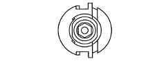
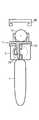
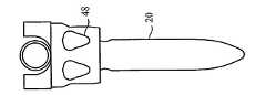
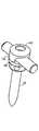
従って、図1では発明に適しているねじ20の側面図を示す。ねじ20には、頭部22および頭部22から伸びる軸24がある。軸24は先細の形をしており、ねじ山が斜めになっている。再度、熟練技術者は他の軸を本発明に適合できることを認識するものと思われる。従って、医師はねじ山の傾斜、ねじ山の直径と軸の直径の比、全体的な軸の形、各患者の骨の状態などに従って多種多様な軸の機能から自由に選択できる。Accordingly, FIG. 1 shows a side view of a
頭部22にはさまざまな形があるが、調整機能を増すために円形頭部で先細のネックを有する頭部が好ましい。よって、留め具20に対応する結合要素26の回転または角度の調整をするために、少なくても頭部の一部はボールの一部を形成するものか、少なくてもネックより上が球形の一部を形成する。このような構成によって、結合要素26は頭部22をさらにしっかりと握ることができる。つまり、少なくても頭部22の一部は軸が広がる時点から曲線状の表面である。頭部の曲線状の部分は半球形であり、頭部の中央から等距離である外部輪郭を示す。さらに、頭部にはねじ回しツールかその他の機器が係合する面がある。つまり、係合する面は曲線状面の機能を妨害しないようにすることが好ましい。The
頭部22の直径は軸24の最大直径とおよそ同じである。さらに多様な角度、および結合本体とねじの位置、あるいは留め具を調整するために、頭部22の湾曲がさらに大きくなるようにネックは先細である。他の実施例では、軸24の直径は頭部22の直径よりも小さくても大きくてもよいこと、さらにネックは先細でなくても異なって先細でもよいことに気付かれたと思う。The diameter of the
また、頭部22には医師がねじを骨にねじ込むためにレンチやねじ回しツールでねじり力あるいは軸力を適用できるように係合する面がある。例えば、頭部22の係合面は、図10で示すようにツールの頭部が係合する多角形の凹部である。たとえば、頭部22はアレン・レンチのような六角形ツールを使用する六角形凹部でもよい。The
また、係合面は突出した係合面で構成されており、突出した係合面は対応するねじ20の結合要素のさまざまな角度に変更する機能を大きく妨害しないようにすることが好ましいが、同様に対応凹部があるツールや機器と係合する。係合面は、同様にスロットやスクリュードライバーのように一般的に使用されている十字型などその他の形でもよい。In addition, the engaging surface is constituted by a protruding engaging surface, and it is preferable that the protruding engaging surface does not greatly hinder the function of changing the coupling element of the
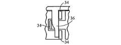
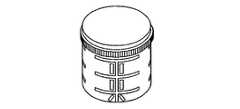
指定位置に固定する前に、頭部26に関連する結合要素26を多数の位置に移動および回転できる。結合要素は、頭部22を第一端部上および反対端部の細長ロッド上に受領する受け入れ面あるいは内面から構成および適用される。固定あるいは締め付けられた位置にあるときに、それと多軸ねじのその他の部品間で即座に係合することができるように、少なくとも頭部の一部に粗面か織物表面があるのがよい。図1の実施例に関しては、結合要素は結合リング28と結合本体30から成る。結合本体は、頭部22を受け取る面や内面を定義するスカート32を有する。できれば、結合要素の受け取る面または内面が締め付けられて頭部22としっかりと固定位置に、または希望に応じて広がったり解除できるように、固定するように、1つ以上のスリットか開口部を提供することでスカートは頭部に対して選択的に固定あるいは解除できればよい。図1に示すように1つの実施例では、結合本体には一般的に1つ以上のらせん状のスリットがある。スリットまたは開口部がねじや留め具20が頭部22以上の位置に隣接するスカートから自由に広がることがさらに好ましい。Prior to locking in a designated position, the
結合本体30にはストップ34が多数あり、結合本体スカート32の上部および下部の端部に配置されているのが好ましい。ストップ34はスリットや開口部が付いたフランジから構成されており、そこからスカート32がスプール形に類似するように結合リングを配置する。結合リング28が結合本体30に接続されるようにストップ34を位置付け、スカート32にねじる力が適用されるとねじられ、頭部22が締め付けられる。The coupling body 30 has a number of
図1に示すように、結合リング28はリング28から広がる1つ、2つ、あるいはそれ以上のアーム36から構成され、ストップ34と係合する。結合リング28が結合本体30の上に配置されると、リングに隣接するアームの低部の近くにある楔形がストップの一つに接触するまで最小限のねじり力がスカートに加えられアーム36が滑らかにストップと係合する。楔形がストップの一つと係合した後、さらに結合本体上にリングを挿入するとスカートの縦軸周辺を回転する。リングが回転すると、アームの遠位端部がストップ34に係合しスカートにねじり力が適用される。1つの実施例では、固定リングは始めの解除位置から固定要素がねじにしっかり固定して固定位置に到達するまで約2〜15度回転する。もう1つの実施例では、固定リングは解除位置から固定位置に約5〜10度回転する。As shown in FIG. 1, the
リングアーム36の遠位端部は、スカートがねじ頭部22に固定するまで十分に回転すると、スカート上のリップと半径方向に係合するように構成する。図2で示すように、例えば、リングアームの先端には突起部38があり、半径方向に内側に広がる。突起部38は、スカートのリップに滑り込み、スカートが固定位置に入るとパチンと閉まる。初めは、スカートが固定位置にないと、隣接す端部から突出部までのリングアームLraの長さがスカートLsの長さより短い。しかしながら、スカートをねじると、全体の長さが次第に減少し、突起部が強制的にリップに押しやられるにつれてリングアームが外側に広がる。スカートLsの長さがリングアームLraの長さとほぼ同じ長さまたは短くなると、突起部はリップから解除され、スカートを固定位置に保持する。本実施例では、結合本体スカート32をねじ頭部22から解除するためには突起部がリップと係合しなくなるまでリングアームに半径方向外側に力を加る。突起部がリップから除去されると、結合リングが回転して結合要素を解除する。このように、結合要素は細長ロッドを固定しなくても、ねじあるいは留め具20に選択的に固定あるいは解除される。よって、結合要素をねじあるいは留め具に固定するために細長ロッドが力を加える必要がない。The distal end of the
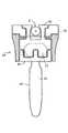
図1に戻って、結合本体もまた、結合本体スカート32が構成されている結合本体30の端部の反対側の上端部に細長ロッドを受けるように構成および適合されている。この部分の結合本体は、細長ロッドが固定されるU字型あるいは楔形の受け入れ面から構成されるのが好ましい。実際、固定した歯あるいは楔形はロッドに向かって受け入れ面から上方に伸びており、キャップ40を受けるスロットや戻り止めで構成される。図3や17で説明されるキャップには、対応する突起部あるいはスロットがあり、対応する結合本体30と係合あるいは回転する。1つの実施例では、キャップを回転することで下方およびねじ方向に移動し、その結果、細長ロッドを固定位置に抑えるために下方に力を加える。Returning to FIG. 1, the coupling body is also constructed and adapted to receive an elongated rod at the upper end opposite the end of the coupling body 30 from which the coupling body skirt 32 is constructed. The connecting body of this part is preferably composed of a U-shaped or wedge-shaped receiving surface to which the elongated rod is fixed. In fact, the fixed tooth or wedge shape extends upwardly from the receiving surface toward the rod and comprises a slot for receiving the
もう1つの実施例では、キャップが細長ロッドに下方に押圧を加え、同様に細長ロッドを完全に固定しないで結合要素が対応留め具に固定される。止めねじがキャップに配置され、細長ロッドをしっかりと位置に固定するために下方に押圧が加えられる。従って、実施例では、ロッドに対してキャップの押圧を下方に加えることで他の部品を調整すると同時に、システムの部品1個を固定するにも十分であるものもある。In another embodiment, the cap presses the elongate rod downward, and the coupling element is secured to the corresponding fastener without similarly securing the elongate rod. A set screw is placed on the cap and a downward pressure is applied to secure the elongated rod in place. Thus, some embodiments may be sufficient to fix one component of the system at the same time as adjusting other components by applying downward pressure on the cap against the rod.
もう1つの代替実施例では、キャップが固定位置方向に回転するにつれて、ロッドに向かって受け入れ面から上方に伸びる結合本体の歯あるいは楔形が屈曲しロッドの周りで動かすことができるようにロッドは柔軟性がある。 例えば、キャップ、歯あるいは楔形、あるいは両方が先細面あるいは傾斜面から構成され、キャップが回転するにつれてキャップや結合要素が徐々に半径方向に妨害される。この妨害により半径方向の力が増えるにつれて、歯や楔形が半径方向内側に湾曲あるいは屈曲して細長ロッドを押圧する。希望のキャップ位置でお互いに係合しながらキャップを固定位置に維持するために、一つ以上の戻り止めおよび凹部をキャップあるいは結合本体に配置する。同様に反対方向にキャップを回転することは細長ロッドを解除することになる。In another alternative embodiment, the rod is flexible so that as the cap rotates in the fixed position, the coupling body teeth or wedges extending upward from the receiving surface toward the rod can be bent and moved around the rod. There is sex. For example, the cap, teeth or wedges, or both, can be tapered or inclined and the cap and coupling elements are gradually disturbed radially as the cap rotates. As the radial force increases due to this obstruction, the teeth and wedges curve or bend radially inward to press the elongated rod. One or more detents and recesses are disposed in the cap or coupling body to maintain the cap in a fixed position while engaging each other at the desired cap position. Similarly, rotating the cap in the opposite direction will release the elongated rod.
よって、発明の実施例では、結合本体が対応するねじの固定位置から解除されなくても細長ロッドを選択的に固定あるいは解除するものがいくつかある。Thus, some embodiments of the invention selectively lock or release the elongated rod without the coupling body being released from the corresponding screw fixing position.
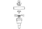
図3−8は、発明のもう1つの実施例の機能や変化をいくつか説明する。本実施例の機能は上述のものと同様のものがいくつかある。例えば、ねじや留め具20は医師の好みによって構成あるいは変更できる。結合要素26が接触する上に頭部22を有する。上述したように、頭部22は一般的に球形である。結合要素26はさまざまな方向に配置あるいは回転可能で、選択的に位置に固定あるいは解除できる。同様に、結合要素は結合本体30とリングアーム28付きの結合リング36を有し、ねじや留め具20に結合要素26を固定できる。Figures 3-8 illustrate some of the features and variations of another embodiment of the invention. The functions of this embodiment have some of the same functions as described above. For example, the screws and
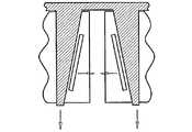
ねじや留め具に結合要素を固定するためにねじれたり回転するスカートを使用する代わりに、本実施例の結合本体は1つ以上の結合本体部品42で形成され、少なくても1個のリングアーム36と滑らかに係合する少なくてもストップ2個で構成されている。図5に示したように、結合本体は少なくてもスリット1個あるいは開口部を有し、結合本体部品の長さに沿って大部分に伸びている。さらに好ましいことには、図5および7の例で示したように、少なくてもスリット1個あるいは開口部が結合本体部品の長さに沿って大部分に伸びている。1つの実施例では、結合本体部品42が増えるにつれて、このようにして構成されたスリットあるいは開口部の数も増える。よって、少なくても2個の結合本体部品42で構成される結合本体30もまた、少なくても2個のスリットあるいは開口部が一般的に結合本体部品の軸の長さに沿って伸びる。Instead of using a twisted or rotating skirt to secure the coupling element to the screw or fastener, the coupling body of this embodiment is formed of one or more
よって、スリットあるいは開口部は形成された物質が対応する終了端部、あるいは1個以上の結合本体部品42が定義する。図5および7に示すように、第一終了端部の一部が対応する第二終了端部の一部の凹部部に突出するように、スリットあるいは開口部の形が構成される。前述のとおり、少なくても2個のストップ34は少なくても1個のリングアーム36と滑らかに係合するように構成する。リングアームの先端部分が1個以上のストップに接触するにつれて、結合要素がねじあるいは留め具の頭部に固定されるように、スリットあるいは開口部を決定する終了端部が互いの方向に強制される。これは、スリットあるいは開口部を決定する終了端部の各側に少なくてもストップを1個設置する。よって、各リングアームは2個以上のストップと接触する。さらに、結合本体を頭部22上に閉じるためには、少なくてもストップ3個が少なくてもリングアーム1個に接触するように構成するのがさらに好ましい。よって、スリットあるいは開口部の先端1個が2個以上のストップを有すのに対して、他のものは1個以上のストップを有す。さらに、各リングアームにはこのように少なくても3個のストップを配置して接触するように構成するのが好ましい。Thus, the slit or opening is defined by the end end to which the formed material corresponds, or one or more
図3、図5、図6Aで示すように、リングアームの先細面が最前線よりもストップの後縁上のストップに接触するように、終了端部あるいは結合本体部品42はさねはぎ流に構成する。しかしながら、終了端部がこのような構成である必要はない。例えば、図6B-Dでは、さねはぎ構成を利用しない本実施例の変化のいくつかを示す。特に、図6Bは複数の楔形がリングアーム36上に提供されることを示す。これによって、さまざまな保持力を頭部22のさまざまな部分に適用できると同様に、結合本体の軸の長さに沿ってストップをさまざまな位置に配置できる 。As shown in FIGS. 3, 5 and 6A, the end or
図6Cは、リングアーム36が固定位置方向に移動するにつれて、終了端部に近づくようにストップが角度をなすことを示す。例えば、ストップの角度は結合要素26の縦軸から約3〜15度離れ、ストップの角度は約5〜10度がさらに好ましい。FIG. 6C shows that as the
図6Dの実施例では、一般的に結合要素26の縦軸に対して垂直の多数のスリットあるいは開口部を使用している。これらのスリットあるいは開口部は一般的に水平帯の外観を作り出す。1つ以上の水平帯の自由端近くに配置されたストップは固定位置方向に移動するにつれてリングアームと滑らかに係合し、よって水平帯の終了面が頭部22をつかむために互いの方向に移動する。The embodiment of FIG. 6D uses a number of slits or openings that are generally perpendicular to the longitudinal axis of the
本書に記述された実施例では、結合本体を固定位置に維持するために固定装置を利用してもよい。上述したように、結合要素を位置に固定するために、結合要素26の縦軸の周りに加えるねじり力 あるいは縦軸に沿って加える軸力のようにさまざまな力を結合リング28やリングアーム36に適用する。図6A−Dでは、1つ以上のリングアームの自由端に固定装置が配置される実施例を示す。In the embodiments described herein, a fixation device may be utilized to maintain the coupling body in a fixed position. As described above, various forces, such as a torsional force applied about the longitudinal axis of the
結合要素26には細長ロッドを受ける面があり、さらに細長ロッドに結合要素を単独に固定するためにキャップと係合する歯がある。実施例では、結合要素は頭部22に圧力を少しあるいは全く加えることなく、留め具頭部にしっかりと固定される。例えば、キャップが結合要素の歯の横に圧力を与えると、同様に細長ロッドをしっかりとつかむために屈曲する。The
図9〜12は、頭部22の周りで結合要素が曲がるように、ストップに力を加えないリングアーム付結合リングを利用しない発明の実施例を示す。代わりに、本実施例では、結合要素を留め具20に固定するためにねじ切りされたロックを多数使用する。例えば、図9では下部クランプ44、上部クランプ46、ねじ切りされたロックナット48、細長ロッドロックナット50から形成される結合要素を示す。FIGS. 9-12 show an embodiment of the invention that does not utilize a coupling ring with a ring arm that does not apply force to the stop so that the coupling element bends around the
図11は、発明の実施例である多軸ねじの組立を示す。上部クランプ46、細長ロッドロックナット50、ねじ切りされたロックナット48をねじ軸24の先端にある留め具20の頭部22の上に設置して組み立てる。それから、ねじ頭をその中央スペースに通して下部クランプ44を頭部22の上に設置する。下部クランプ44は、できればねじ切りされたロックナット48のねじ山と係合するようにねじ山があればよい。これらのねじ山が次第に係合し、結合要素がしっかりと固定するまで上部クランプ44および下部クランプ46を徐々に頭部22に固定する。FIG. 11 shows the assembly of a polyaxial screw which is an embodiment of the invention. The
図9は、ねじ切りされたロックナットが回転するにつれて、上部クランプと下部クランプの接合部分がクランプの回転を妨げる形で係合する状態を示す。1つの実施例では、上部クランプおよび下部クランプがクランプ要素に対応する角ばった歯を使用する。また、相互接続面には、鋸歯状の歯、歯止めなどのようなその他のパターンを使用してもよい。端部は、クランプ要素の回転を防止するためにスターグラインドのような粗面でもよいが、表面が相互接続し回転抵抗があるように相互接続面が大型のものを使用する方が好ましい。FIG. 9 shows the state where the upper and lower clamp joints engage in a manner that prevents rotation of the clamp as the threaded lock nut rotates. In one embodiment, the upper and lower clamps use angular teeth corresponding to the clamping elements. Also, other patterns such as serrated teeth, pawls, etc. may be used on the interconnect surfaces. The ends may be rough surfaces such as star grinds to prevent rotation of the clamping elements, but it is preferred to use large interconnect surfaces so that the surfaces are interconnected and have rotational resistance.
結合要素の歯が屈曲してロッドをつかむように、細長ロッドロックワッシャやナットを回転して細長ロッドを位置に固定する。図9に示すように、歯はクランプ上部に形成する。本実施例では、細長ロッドを位置に固定するために使用する前述のキャップは使用しない場合がある。例えば、細長ロッドロックワッシャにはその内面に1つ以上の円形でないものがあり、ワッシャが回転するときに歯が細長ロッドの周りをきつく屈曲するように促す。できれば、ワッシャを約5〜25度回転すれば、細長ロッドが固定あるいは解除できればよい。さらに、ワッシャは約10〜25度回転できればよい。必要であれば、ロッドが位置にしっかりと固定されるようにキャップを使用してもよい。また、さらにしっかりと細長ロッドに固定するために、止めねじを使用してもよい。The elongated rod lock washer and nut are rotated to fix the elongated rod in position so that the teeth of the coupling element bend and grip the rod. As shown in FIG. 9, the teeth are formed on the top of the clamp. In this embodiment, the above-described cap used to fix the elongated rod in position may not be used. For example, some elongated rod lock washers have one or more non-circular inner surfaces that encourage teeth to bend tightly around the elongated rod as the washer rotates. If possible, the elongated rod can be fixed or released by rotating the washer by about 5 to 25 degrees. Furthermore, the washer only needs to be able to rotate about 10 to 25 degrees. If necessary, a cap may be used to secure the rod in position. A set screw may also be used to secure the elongated rod more firmly.
図13および14では、結合本体スカート内にスロットや開口部が形成されているものを使用する発明のもう1つの実施例を示す。本実施例では、結合本体スカートの角度は約5〜30度がよく、さらに約7〜15度の角度が好ましい。 結合要素の先細が結合本体スカート32の先細部分の直径をねじ軸24の隣接端部から細長ロッドの近くにある上端部まで 徐々に広げることを図で示しており、 先端を反転できるので熟練技術者には利点になる。FIGS. 13 and 14 show another embodiment of the invention that uses slots and openings formed in the coupling body skirt. In this embodiment, the angle of the coupling body skirt is preferably about 5-30 degrees, more preferably about 7-15 degrees. The taper of the coupling element shows that the diameter of the tapered part of the coupling body skirt 32 gradually widens from the adjacent end of the
結合本体スカートの周りに設置される固定リング52は、単に結合本体スカート32の先細面に沿って軸方面に移動すると、結合要素を留め具20にしっかりと留めることができる。図9〜11の実施例に対して本実施例の利点は、ねじ切りされたロックナットにレンチを使用する必要がないことである。さらに、本実施例では、結合本体を4つの要素で形成される代わりに2つで形成できる。よって、本実施例は、その他の実施例に対して少なくても操作性と設計の単純化という点で有利である。The securing
操作は、結合要素が希望の位置に設定されると、固定リング52が結合本体スカートの軸に沿って縦に移動される。 リングが移動すると、スカートの先細領域が係合し圧力が加えられ、同様にスカートが頭部22の方向に屈曲する。図には示されていないが、細長ロッドを結合本体に単独に固定するために第二リングをスカートに使用してもよい。例えば、結合要素の受け入れ面内にロッドを置いた後、細長ロッド上に届く歯を提供して実施する。In operation, when the coupling element is set to the desired position, the retaining
上述したように、結合要素26を留め具20に固定する方法で、細長ロッドを固定するために構成および適応した先細の第二結合本体スカートの軸に沿って第二固定リングを移動する。固定リングを固定位置方向と同じ方向に移動すると、移動方向が第二固定リングを解除位置に動かしてしまう。つまり、本実施例では、多軸ねじのすべての部品を固定することで固定リングを遠くに移動するか、それらを移動することで互いの方向で移動するように結合要素を構成すると有利である。As described above, the second securing ring is moved along the axis of the tapered second coupling body skirt configured and adapted to secure the elongated rod in a manner that secures the
細長ロッドを固定するもう1つの方法は、キャップ40を使用することである。本書に記述したキャップなど細長ロッドを固定するために設計されたキャップを使用して細長ロッドを結合要素としっかりと接続する。Another way to secure the elongate rod is to use a
一般的に、上述の実施例では、脊椎の少なくても一部がかなり堅固で不動なものを確立する際に使用する。しかしながら、脊椎の少なくても一部にある程度の柔軟性を与えてくれるシステムを使用することが有利な場合もある。図15および16で示す実施例では、発明の見地を説明しており、部品が固定された後でも屈曲できる留め具20を使用する。発明を実施するために必要ではないが、留め具や結合要素を一体化して形成する実施例が好まれる。In general, the embodiments described above are used in establishing at least a portion of the spine that is fairly rigid and immobile. However, it may be advantageous to use a system that provides some flexibility to at least a portion of the spine. The embodiment shown in FIGS. 15 and 16 illustrates an inventive aspect and uses a
結合要素には1つ以上のスリットや開口部があり、屈曲性の範囲が限られる。例えば、結合要素には約2〜7度の屈曲性がある。このような屈曲性を提供するには、結合要素に1つ以上のスリットあるいは開口部を表面に形成する。1つの実施例では、結合要素内のスリットあるいは開口部は一般的にらせん形状である。その他の屈曲性のある構造を使用してもよい。例えば、米国特許番号登録第10/443,755号申請日2003年5月23日は、全体的に本書に組み込まれており、本発明で使用される屈曲性のある結合要素の方法や構成がいくつか説明されている。さらに、米国特許番号登録第10/762,533号申請日2004年1月23日も全体的に組み込まれており、本発明で使用される結合要素の方法や構成がいくつか説明されている。The coupling element has one or more slits or openings that limit the range of flexibility. For example, the coupling element has a flexibility of about 2-7 degrees. To provide such flexibility, one or more slits or openings are formed in the surface of the coupling element. In one embodiment, the slits or openings in the coupling element are generally helical. Other flexible structures may be used. For example, U.S. Patent No. 10 / 443,755, filed May 23, 2003, is incorporated herein in its entirety, and there are several methods and configurations for flexible coupling elements used in the present invention. Explained. In addition, US patent application Ser. No. 10 / 762,533, filed Jan. 23, 2004, is generally incorporated and describes several methods and configurations for the coupling elements used in the present invention.
細長ロッドを受け入れる面を一体化して留め具に形成するが、再度、このような構成は発明を実施するためには必要はない。受け入れる面は前述の方法で多数の歯を形成する、あるいは固定キャップ54がロッド上に設置されるねじ切りされた面を使用する。固定キャップが回転するにつれて、ロッドが位置に固するまで下部面は細長ロッドの上部面に圧力を加える。Although the surface to receive the elongated rod is integrated into the fastener, again such a configuration is not necessary to practice the invention. The receiving surface forms a number of teeth in the manner described above, or uses a threaded surface on which a fixing cap 54 is placed on the rod. As the locking cap rotates, the lower surface exerts pressure on the upper surface of the elongated rod until the rod locks into position.
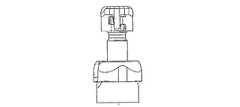
図17〜19は、結合要素26を留め具20に締め付けるために複数の部品で構成されたねじ切りされたロックナットを利用する発明のもう一つの実施例を示す。図17に示すように、結合要素26は下部クランプ要素44、上部クランプ要素46、ねじ切りされたロックナット48から成る。下部クランプ要素44および上部クランプ要素46は相互接続する端部を有し、結合すると対応するクランプ要素が回転しないようにする。図17に示すように、例えば、下部クランプ要素44および上部クランプ要素46が相互接続する端部には相互接続する歯のパターンがある。熟練技術者は、クランプ要素がお互いに回転しないようにその他の相互接続する端部を利用できることに気付くものと思われる。FIGS. 17-19 illustrate another embodiment of the invention that utilizes a threaded lock nut comprised of a plurality of parts to tighten the
下部クランプ要素44の一部は、ねじ切りされたロックナット48の内面に対応するねじ込みを受けるために、その外面にねじ山がついている。ねじ込みロックナット48を締め付けると、結合本体30が頭部22に固定するために下部クランプ要素44および上部クランプ要素46がお互いの方向に移動する。A portion of the
下部クランプ要素44および上部クランプ要素46には受け入れ面があり、留め具頭部22の局面の一部に合致する。できれば、頭部22の円形あるいは半球形部分の曲率半径は、下部クランプ要素44および上部クランプ要素46の受け入れ面の曲率半径と実質的に同じである。しかしながら、クランプ要素が頭部22に完全に接触すると、ギャップあるいは開口部が相互接続する端部の上層部あるいは下層部の間にそのまま残る。例えば、下部クランプ要素44の上部に伸びている角ばったさねの最上端部と上部クランプ要素46に対応する角ばった溝の最上端部の間にある空間の高さは約0.1〜5mmである。The
上部クランプ要素46は、下部クランプ要素44の端部と相互接続する下部端部を有するが、相互接続する端部から遠位の上端部を有し、細長ロッドを受け入れる面を形成するために結合本体のその他の要素を係合する。特に、上部クランプ要素46の遠位端部はねじ切りされたロックナット48の上方に伸び、ねじ切りされたロックナット48の上方に設置したロッドおよび固定要素58に形成したアパーチャを通る。ロッドおよび固定要素58には細長ロッドを受ける曲面があるが、上部クランプ要素46の遠位端部を受けるために凹部60で構成されている。The
特に、上部クランプ要素46の遠位端部には2個以上のウィング56があり、上部クランプ要素46の遠位端部から半径方向に外側に伸びている。図17で示すように、切り欠きがウィング56と一列に並んで、ウィングがねじ切りされたロックナット48、ロッド、固定要素58を通り抜ける。ウィングがロッドの受け入れ面および固定要素58の上に配置されると、上部クランプ要素46か固定要素58のどちらかが、凹部60がウィング56と一列に並ぶまで回転する。それから、ウィング56が凹部60内に配置され、細長ロッドが配置される受け入れ面が形成される。In particular, the distal end portion of the
細長ロッドが固定要素58の受け入れ面および上部クランプ要素46のウィング56に配置されると、固定キャップ62が固定要素58に加わり、結合要素26がロッドにしっかりと接続される。キャップ62および固定要素58が細長ロッドに適用する力はさまざまである。1つの実施例では、固定キャップは、固定要素58に固定されているので細長ロッドに下方へ力を加えるように構成されている。図17に示すように、固定要素58にはキャップを下方に移動するためにロッド上のキャップ62と係合する1個以上のタブがある。When the elongate rod is placed on the receiving surface of the securing
図19を参照にすると、キャップには湾曲うねあるいは歯66が内面にあるキャップの外周の一部に沿って伸びている。湾曲うね66の長さは、細長ロッドの上を固定位置から解除位置まで移動するときのキャップが受ける量や回転により判断する。例えば、1つ以上の湾曲うねはキャップの約3〜30度まで伸び、さらに約10〜20度まで伸びるのが好ましい。湾曲うね66はタブ64の底面と係合する。Referring to FIG. 19, the cap has curved ridges or
湾曲うね66かタブ64のどちらか、あるいは両方が円形でない面を作成するように構成され、固定位置方向に回転するにつれてキャップを下方へ押しやる。タブやうねも1つ以上の戻り止めや凹部で構成されており、キャップが固定位置に達したら医師が感じたり聞いたりできるクリック音のような触覚的あるいは聴覚的合図を提供できる。また、戻り止めや凹部はキャップが固定位置に維持できるようにする。Either the
図17を参照すると、好ましい実施例では固定要素58にはタブ64の下に外面68があり、一般的に円筒型である。同様にキャップ62には一般的に対応する円筒型面70があり、同様の直径である。キャップを固定要素上に設置すると、キャップは固定位置に方向に回転するので、これら2面は固定要素58にキャップ62を半径方向に位置するように支援する。Referring to FIG. 17, in the preferred embodiment, the securing
もう1つの実施例では、図9および14と同様な方法で固定要素58およびキャップ62はロッドを位置に固定するためにロッドの周りの受け入れ面の一部を圧迫する。よって、この代替実施例には、一般的に円筒型面68および70の修正を伴っており、固定要素の一部上に半径内向きに力を加える円形でない面を作り出す。キャップ62が固定位置方向に回転するにつれて半径方向力が増し、固定要素58の一部を屈曲したり細長ロッドを押圧する。In another embodiment, locking
図17〜19に示すように、本実施例のキャップは側壁72を有し、キャップ62上部からねじ軸24方向に伸びる。キャップの側壁72はリップの近くあるいは固定要素58の底面で終了し、両方の要素はおよそ同様の外径であることが好ましい。細長ロッドの上にキャップを設置するために、側壁72はカットアウトあるいは切り欠き74を有し、キャップが固定位置あるいは解除位置であろうとも固定要素58上に設置されたときロッドが側壁72を通して伸びる。よって、一般的にカットアウトあるいは切り欠きの長さはキャップを固定位置にあるいは固定位置から移動するために必要な回転数に一致する。また、キャップ62、固定要素58、ロッドの設計に許容誤差を含んでいるのでカットアウト74はキャップ62が回転するのに必要な大きさよりも若干大きい。例えば、カットアウト74はキャップ62を固定あるいは解除するのに必要な回転よりもさらに約1〜5度余分に回転できる。As shown in FIGS. 17-19, the cap of a present Example has the
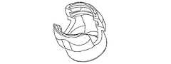
本書に記述されたさまざまな実施例の機能あるいは要素は、本発明の精神と範囲から逸脱することなく変更および/あるいは他の実施例と使用できる。図20〜25では発明のもう一つの実施例を示しており、上述のさまざまな機能あるいは要素を使用する。図20〜24では、本実施例の部品の構成、調整、組立を示す。図21に示すように、例えば、結合要素26は結合本体と結合リングにより形成される。結合本体は1個、2個、あるいはそれ以上の結合本体部品と少なくても1個できれば2個、スリットあるいは開口部が結合本体の軸の長さに沿って完全に、そうでなければ部分に伸びる。スリットあるいは開口部は直線である必要はないが、結合本体部品42の物質の終了端部が判断する。 図20、23および24では、結合本体部品の終了端部がさねはぎ構造で構成されている。 同様に、図7および8に示すように単独の結合本体部品は多数の結合本体部品を設置するのに使用する。The functions or elements of the various embodiments described herein can be modified and / or used with other embodiments without departing from the spirit and scope of the present invention. 20-25 illustrate another embodiment of the invention that uses the various functions or elements described above. 20 to 24 show the configuration, adjustment, and assembly of the parts of this embodiment. As shown in FIG. 21, for example, the
同様に、第一および第二突出部の大部分が層状にあるいは共に重ね合わせられるように、終了端部が反対側の終了端部が決定したほとんど水平の第二突出部上に設置したほとんど水平の第一突出部を決める。ストップは各スリットの近くの結合本体部品に配置する。スリットあるいは開口部の反対側に少なくてもストップ1個ある。よって、2個の結合本体部品を使用する例では、両方の部品には少なくてもストップが2個ある。結合本体部品は円形留め具頭部の周りに配置する。その後に、結合本体部品の上にリンクを押圧あるいは下方に低くする。リングが低くなると、1個以上のアームが滑らかにストップと係合する。さらに、リングおよびアームを下方に移動すると結合本体部品が留め具頭部をしっかり掴む。図24は、アームが楔形を決定し、結合本体部品のストップを互いを引き離すように押す。同様に、留め具頭部の上に部品がさらに大きな保持力を加える。Similarly, the most end of the first and second protrusions are layered or stacked together so that the end end is located almost horizontally on the almost horizontal second protrusion determined by the opposite end end. Determine the first protrusion. A stop is placed on the coupling body part near each slit. There is at least one stop on the opposite side of the slit or opening. Thus, in an example using two coupled body parts, both parts have at least two stops. The coupling body part is placed around the circular fastener head. Thereafter, the link is pressed or lowered downward on the coupling body part. When the ring is lowered, one or more arms smoothly engage the stop. Further, as the ring and arm are moved downward, the coupling body part grips the fastener head. FIG. 24 shows that the arm determines the wedge shape and pushes the stops of the coupling body parts away from each other. Similarly, the part exerts a greater holding force on the fastener head.
しかしながら、熟練技術者にとっては、留め具頭部をしっかりと掴むために前述の構成などその他のストップ構成を使用できるのでよい。例えば、図1および6B-Eに示す構成は、留め具頭部に加えた保持力を増やすために、ストップをさらに近くに押すためにも使用する。However, for skilled technicians, other stop configurations such as those described above may be used to securely grasp the fastener head. For example, the configuration shown in FIGS. 1 and 6B-E is also used to push the stop closer to increase the holding force applied to the fastener head.
図24に戻って、結合本体部品はねじ頭部を掴むために結合して構成する。本実施例では、第一結合本体部品には、各側に2個の突起部あるいはアームがあり、その間に凹部を決定するために外側に伸びる。それから、第二結合本体部品は各側のアーム1個で構成され、一般的に第一部品に形成された凹部に対応する。Returning to FIG. 24, the coupling body parts are joined together to grasp the screw head. In this embodiment, the first coupling body part has two protrusions or arms on each side and extends outward to determine a recess therebetween. The second coupling body part is then composed of one arm on each side and generally corresponds to a recess formed in the first part.
結合本体部品の内面はねじ頭部をしっかりと掴むことができるように粗くざらざらである。 図のように、内面は多数の溝や円形切り抜きでざらざらしている。両部品の内面はその上に形成された同様の織目か、あるいはその代わりに別の織目あるいは別の織目の方向性がある。例えば、第一内面の溝あるいは円形切り抜きの方向と第二内面の内面の溝あるいは円形切り抜きの間に形成された角度が約60〜90度であるように、第一内面の溝あるいは円形切り抜きは一般的に水平方向を向くなど一つの方向を向いているに対して、第二内面の内面の溝あるいは円形切り抜きは垂直方向などさまざまな方向を向いている。1つの実施例では、留め具頭部に加えられた保持力によって溝が変形したり反対の溝付面が切り抜かれたりして表面の一部が突出する。その結果、部品の意図的でない抵抗移動あるいは再配列がおきる。さらに、らせん状の溝が留め具頭部の一部か1つ以上の結合要素の掴み面のどちらか、あるいは両方にある。The inner surface of the coupling body part is rough and rough so that the screw head can be gripped firmly. As shown in the figure, the inner surface is rough with a large number of grooves and circular cutouts. The inner surfaces of both parts have a similar texture formed thereon, or alternatively have a different texture or another texture orientation. For example, the groove or circular cutout on the first inner surface is such that the angle formed between the direction of the groove or circular cutout on the first inner surface and the groove or circular cutout on the inner surface of the second inner surface is about 60 to 90 degrees. In general, it faces in one direction such as in the horizontal direction, while the groove or circular cutout on the inner surface of the second inner surface faces in various directions such as the vertical direction. In one embodiment, the groove is deformed by the holding force applied to the fastener head or the opposite grooved surface is cut out and a part of the surface protrudes. As a result, unintentional resistance movement or rearrangement of parts occurs. In addition, there are spiral grooves in either or both of the fastener heads, the gripping surfaces of one or more coupling elements.
結合本体部品がねじ頭部の周りに設置されると、結合本体部品がねじ頭部をしっかり掴まえるためにリングアームの下方に伸びるアームがストップと係合し始めるように、リングアーム36は結合要素に設置される。その上、結合本体部品およびねじ頭部をスカートに下げる。図25に戻って、スカートの下部にはリップあるいは保持リングがあり、留め具や頭部の周りに配置した組立部品を支援する。リップは単一面でスカート下部周辺全体の内側に伸びるか、あるいは組立部品がスカートの下端部を通過しないように多数のタブあるいは突出部を形成する。留め具頭部および組立部品の一部はリップに支えられおり、リップのほとんど同じ部分に軸を配置するように構成される。1つの実施例では、組立が接触するリップ面は大部分が平坦でスカートの縦軸に対して垂直な平面である。リップの接触面は円錐台、一部球形、鋸歯、図9などに示すようなねじ山のような形などがある。When the coupling body part is installed around the screw head, the
リップ上は、スカートは組立部品を設置する場所に凹部を形成する。それから、上述した方法でリングアームは組立の上に設置する。リングアームは屈曲面の上部に構成されており、細長ロッドを受け取る形をしている。また、スカートの上部には開口部あるいはスロットがあり、細長ロッドを受ける。On the lip, the skirt forms a recess where the assembly is to be placed. The ring arm is then installed on the assembly in the manner described above. The ring arm is configured at the upper part of the bent surface and receives the elongated rod. There is an opening or slot at the top of the skirt to receive the elongated rod.
ロッドがスカートの開口部やスロットを通り抜けリングアーム受け取り面に押圧されると、リングアームをさらに下方へ促し、その結果、結合要素がさらにねじ頭部に近づく。 しかしながら、ねじ頭部に加えられた力は、スカートや組み立て部品が完全に回転、移動、調整しないようにするものではない。それから、キャップはロッド上のスカートに低下する。図25で示すように、キャップには拡大開口部あるいはスロットが2個あり、スカートの開口部よりも広く細長ロッドの直径よりも広く、スカートの中に設置する。本実施例では、開口部あるいはスロットの側壁がロッドに妨害されないでキャップが回転する。 開口部あるいはスロットは、キャップの回転が約5〜90度回転できるように構成されるか、あるいはキャップが約15〜60度回転するようにするのが好ましい。もう一つの実施例では、キャップの開口部あるいはスロットはロッドに妨害されないでキャップが約20〜40度回転するように構成されている。As the rod passes through the skirt opening or slot and is pressed against the ring arm receiving surface, the ring arm is further urged downward, so that the coupling element further approaches the screw head. However, the force applied to the screw head does not prevent the skirt or assembly from completely rotating, moving or adjusting. Then the cap falls to the skirt on the rod. As shown in FIG. 25, the cap has two enlarged openings or slots, which are wider than the opening of the skirt and wider than the diameter of the elongated rod, and are installed in the skirt. In this embodiment, the cap rotates without the opening or slot sidewall being obstructed by the rod. The opening or slot is preferably configured such that the rotation of the cap can be rotated about 5 to 90 degrees, or the cap can be rotated about 15 to 60 degrees. In another embodiment, the cap opening or slot is configured so that the cap rotates approximately 20-40 degrees without being obstructed by the rod.
キャップが第一の位置に回転すると、不注意に除去されないようにスカートと係合する。この位置では、ロッドはスカートやキャップの開口部から自由に移動あるいは戻り、スカートをねじや留め具に対して調整あるいは移動する。しかしながら、キャップが第二位置に回転するにつれて、拡大開口部あるいはスロット上部の円形でない面あるいは傾斜面が、ロッドがリングアームに下向きに促し、結果的にスカートが対応するねじや留め具の方向に動かないようにリングアームと結合本体部品が留め具頭部をしっかりと掴む。上述したように、このように結合本体部品を固定するとキャップが細長ロッドがスカートに完全に固定しない。 実際、結合本体を留め具頭部に固定すると、不注意に結合本体が留め具頭部から解除されないでキャップが解放され細長ロッドを再配置する。As the cap rotates to the first position, it engages the skirt so that it is not inadvertently removed. In this position, the rod is free to move or return from the opening of the skirt or cap, adjusting or moving the skirt relative to the screw or fastener. However, as the cap rotates to the second position, the non-circular or slanted surface of the enlarged opening or top of the slot causes the rod to urge the ring arm downwards, resulting in the direction of the corresponding screw or fastener in the skirt. The ring arm and coupling body part firmly hold the fastener head so that it does not move. As described above, when the coupling body part is fixed in this way, the cap does not completely fix the elongated rod to the skirt. Indeed, when the coupling body is secured to the fastener head, the coupling body is not inadvertently released from the fastener head and the cap is released and the elongated rod is repositioned.
代わりに、キャップは、第二固定位置方向へ回転するにつれて、さらにスカートの下方へ促される。キャップが低くなると、円形でない面あるいは斜面があるかもしれない拡大開口部あるいはスロットの上部がリングアーム に対してロッドを押圧する。例えば、キャップとスカートはねじ山で構成され、一つの方向に回転するとキャップをスカートに引き付け、反対方向に回転するとキャップがスカートを解放する。Instead, the cap is urged further down the skirt as it rotates toward the second fixed position. As the cap is lowered, the enlarged opening or upper part of the slot, which may have a non-circular surface or bevel, presses the rod against the ring arm. For example, the cap and skirt are threaded, and rotating in one direction will attract the cap to the skirt, and rotating in the opposite direction will release the skirt.
キャップが第一位置あるいは第二位置、あるいは両方の位置に到達すると、スカートおよび/あるいはキャップが触覚的感覚あるいは聴覚的クリック音を出すことが好ましい。この利点は、医師は部品が希望の位置に収まったという確認ができる。さらに、キャップあるいはスカートには1つ以上の戻り止めあるいは同様の構造があり、キャップが第一位置あるいは第二位置に不注意に戻らないようにする。Preferably, the skirt and / or cap makes a tactile sensation or an audible click when the cap reaches the first position, the second position, or both. This advantage allows the physician to confirm that the part is in the desired position. In addition, the cap or skirt has one or more detents or similar structures to prevent the cap from inadvertently returning to the first or second position.
キャップが第二位置に設置されると、スカートおよび留め具は相互に対応する固定の位置にあるが、ロッドはスカートやキャップの開口部からすり抜ける可能性がある。キャップは上面にアパーチャがあり、止めねじを利用してロッドを希望の位置にしっかりと設置する。When the cap is installed in the second position, the skirt and fasteners are in fixed positions corresponding to each other, but the rod may slip through the opening of the skirt or cap. The cap has an aperture on the top surface and uses a set screw to securely place the rod in the desired position.
上述の多くの実施例で示したように、本発明は医師が脊椎固定システムを取付あるいは調整する際にかなりの柔軟性を提供する。実際のところ、医師は脊椎の治療部位に留め具を複数取り付ける。留め具20は結合要素26で構成されており、さまざまな位置に移動および回転できる。医師は、細長ロッドを位置に固定しなくても結合要素26を希望の位置に固定できる。同様に、ロッドを結合要素に固定した後でも、医師は結合要素26を留め具20から解除できる。よって、医師は留め具20に対応する結合要素26の回転や角度をいつでも調整できる。As shown in many of the embodiments described above, the present invention provides considerable flexibility when a physician installs or adjusts the spinal fixation system. In fact, doctors attach multiple fasteners to the spinal treatment site.
要約して言えば、上述の実施例は、本発明は従来技術が到達した利点だけでなくさまざまな利点を提供することを示す。例えば、ロッド固定装置および結合固定装置を単独で固定および解除することによって得られる利点としては、多軸ねじは過去に達成したものよりも極めて大きな調整機能を可能にする。ロッドと結合装置間の接続を調整する際に、結合装置を設置するための希望の位置を失うという危険は必要ない。 よって、本発明では微調整が可能であるのに対して、前システムで避けられないものは部品を再配置するために全ての部品を緩めなければならない。In summary, the above-described embodiments show that the present invention provides various advantages as well as the advantages reached by the prior art. For example, as an advantage gained by fixing and releasing the rod fixing device and the coupling fixing device alone, the polyaxial screw allows a much greater adjustment function than has been achieved in the past. When adjusting the connection between the rod and the coupling device, there is no need to risk losing the desired position for installing the coupling device. Thus, while fine adjustment is possible in the present invention, all the parts that are inevitable in the previous system must be loosened in order to reposition the parts.
卓越した調整機能に加えて、本発明は脊椎固定システムを取り付けるための複雑性および外科手術の手順を減らした。また、本発明は過去に到達したコンパクト設計よりもさらにコンパクトで、インプラントに使用する個々の部品数も減らした。全体的に、これらの利点は手術に要する時間の削減および手術手順の単純化にもつながり、幅広い患者の構造にも効果がある。In addition to outstanding adjustment capabilities, the present invention has reduced the complexity and surgical procedure for installing a spinal fixation system. The present invention is also more compact than the compact design reached in the past and has reduced the number of individual parts used in the implant. Overall, these benefits also reduce the time required for surgery and simplify the surgical procedure, and are effective for a wide range of patient structures.
ここに公開された発明は上述の目的を果たすようによく計画されていることは明確であるが、技術的に熟練した者による多数の修正および実施例を考案いただければ有り難い。従って、追加請求事項が本発明の精神と範囲内にあるそのような全ての修正および実施例を補うことを目的とする。While it is clear that the invention disclosed herein is well-planned to fulfill the above objective, it would be appreciated if numerous modifications and embodiments could be devised by those skilled in the art. Accordingly, it is intended that the appended claims cover all such modifications and embodiments that are within the spirit and scope of the present invention.
Claims (3)
Translated fromJapanese固定要素および円形頭部を有す骨留め具と、
該固定要素に近接する該頭部の第一端部に設定され、上部クランプ要素に対応して軸方向に移動可能な下部クランプ要素であって、該下部クランプ要素が該頭部の円形面の一部を受け入れるためのほぼ対応する受け入れ面および外面を含み、少なくとも該外面の一部がねじ切りされている、下部クランプ要素と、
該固定要素より遠位の該頭部の第二端部に設定される上部クランプ要素であって、該下部クランプ要素および上部クランプ要素が対応するクランプの回転を制限するために相互的に接続する突出部および切り欠きを有する、上部クランプ要素と、
該下部および上部クランプ要素のほぼ周りに設定される固定要素であって、固定要素が少なくても一部がねじ切りされた内面を含み、該固定要素の該ねじ切りされた部分が該下部クランプ要素の該ねじ切りされた部分と係合した場合に、下部クランプ要素と上部クランプ要素とが互いの方向に移動して円形頭部を固定する、固定要素と、
該上部クランプ要素および該固定要素と係合し、該細長ロッドを受け入れる受け入れ面を含む、ロッド固定要素とを含む、
結合要素と、
該細長ロッドを該結合要素に固定するために該ロッド固定要素と選択的に係合することが可能な固定キャップとを含む、脊椎固定システム。An elongated rod,
A bone fastener having a fixation element and a circular head;
A lower clampingelement set at a first end of the head proximate to the fixing element and movable in an axial direction corresponding to the upper clampingelement , wherein the lower clampingelement is of a circular surface of the head A lower clamping element comprising substantially corresponding receiving and outer surfaces for receiving a portion, at least a portion of the outer surface being threaded;
An upper clamping element set at the second end of the head distal to the fixation element, the lower clampingelement and the upper clampingelement interconnecting to limit rotation of the corresponding clamp An upper clamping element having a protrusion and a notch;
A fixing element that is set around approximately said lower and upper clamp element comprise a portion be less anchoring element is threaded inner surface, the threaded portion of the fixingelement ofthe lower clamping elementwhen engaged with said threadedportion, and a lower clamp element and an upper clamping element for fixing the circular head to move towards each other, and the fixed element,
A rod securing element that includes a receiving surface that engages the upper clampelement and the securing element and receives the elongate rod;
A binding element;
The elongated rod and a fixing cap that is capable of selective engagement with the rodfixed element to be fixed to the coupling element, a spinal fixation system.
Applications Claiming Priority (3)
| Application Number | Priority Date | Filing Date | Title |
|---|---|---|---|
| US10/819,994 | 2004-04-08 | ||
| US10/819,994US7503924B2 (en) | 2004-04-08 | 2004-04-08 | Polyaxial screw |
| PCT/US2005/011918WO2005099400A2 (en) | 2004-04-08 | 2005-04-08 | Polyaxial screw |
Publications (2)
| Publication Number | Publication Date |
|---|---|
| JP2007532199A JP2007532199A (en) | 2007-11-15 |
| JP4929157B2true JP4929157B2 (en) | 2012-05-09 |
Family
ID=35061552
Family Applications (1)
| Application Number | Title | Priority Date | Filing Date |
|---|---|---|---|
| JP2007507525AExpired - LifetimeJP4929157B2 (en) | 2004-04-08 | 2005-04-08 | Multi screw |
Country Status (4)
| Country | Link |
|---|---|
| US (4) | US7503924B2 (en) |
| EP (1) | EP1732457B8 (en) |
| JP (1) | JP4929157B2 (en) |
| WO (1) | WO2005099400A2 (en) |
Families Citing this family (223)
| Publication number | Priority date | Publication date | Assignee | Title |
|---|---|---|---|---|
| US7833250B2 (en) | 2004-11-10 | 2010-11-16 | Jackson Roger P | Polyaxial bone screw with helically wound capture connection |
| US6726689B2 (en)* | 2002-09-06 | 2004-04-27 | Roger P. Jackson | Helical interlocking mating guide and advancement structure |
| US8377100B2 (en)* | 2000-12-08 | 2013-02-19 | Roger P. Jackson | Closure for open-headed medical implant |
| US10258382B2 (en) | 2007-01-18 | 2019-04-16 | Roger P. Jackson | Rod-cord dynamic connection assemblies with slidable bone anchor attachment members along the cord |
| US10729469B2 (en) | 2006-01-09 | 2020-08-04 | Roger P. Jackson | Flexible spinal stabilization assembly with spacer having off-axis core member |
| US8292926B2 (en) | 2005-09-30 | 2012-10-23 | Jackson Roger P | Dynamic stabilization connecting member with elastic core and outer sleeve |
| US7862587B2 (en) | 2004-02-27 | 2011-01-04 | Jackson Roger P | Dynamic stabilization assemblies, tool set and method |
| US8353932B2 (en) | 2005-09-30 | 2013-01-15 | Jackson Roger P | Polyaxial bone anchor assembly with one-piece closure, pressure insert and plastic elongate member |
| US8257402B2 (en)* | 2002-09-06 | 2012-09-04 | Jackson Roger P | Closure for rod receiving orthopedic implant having left handed thread removal |
| US8282673B2 (en)* | 2002-09-06 | 2012-10-09 | Jackson Roger P | Anti-splay medical implant closure with multi-surface removal aperture |
| US8876868B2 (en)* | 2002-09-06 | 2014-11-04 | Roger P. Jackson | Helical guide and advancement flange with radially loaded lip |
| WO2006052796A2 (en) | 2004-11-10 | 2006-05-18 | Jackson Roger P | Helical guide and advancement flange with break-off extensions |
| US20060009773A1 (en)* | 2002-09-06 | 2006-01-12 | Jackson Roger P | Helical interlocking mating guide and advancement structure |
| US8540753B2 (en) | 2003-04-09 | 2013-09-24 | Roger P. Jackson | Polyaxial bone screw with uploaded threaded shank and method of assembly and use |
| US6716214B1 (en) | 2003-06-18 | 2004-04-06 | Roger P. Jackson | Polyaxial bone screw with spline capture connection |
| US7621918B2 (en) | 2004-11-23 | 2009-11-24 | Jackson Roger P | Spinal fixation tool set and method |
| US7377923B2 (en) | 2003-05-22 | 2008-05-27 | Alphatec Spine, Inc. | Variable angle spinal screw assembly |
| US8398682B2 (en) | 2003-06-18 | 2013-03-19 | Roger P. Jackson | Polyaxial bone screw assembly |
| US8366753B2 (en)* | 2003-06-18 | 2013-02-05 | Jackson Roger P | Polyaxial bone screw assembly with fixed retaining structure |
| US8092500B2 (en)* | 2007-05-01 | 2012-01-10 | Jackson Roger P | Dynamic stabilization connecting member with floating core, compression spacer and over-mold |
| US20110040338A1 (en)* | 2003-08-28 | 2011-02-17 | Jackson Roger P | Polyaxial bone anchor having an open retainer with conical, cylindrical or curvate capture |
| US8377102B2 (en)* | 2003-06-18 | 2013-02-19 | Roger P. Jackson | Polyaxial bone anchor with spline capture connection and lower pressure insert |
| US8257398B2 (en) | 2003-06-18 | 2012-09-04 | Jackson Roger P | Polyaxial bone screw with cam capture |
| US8926670B2 (en) | 2003-06-18 | 2015-01-06 | Roger P. Jackson | Polyaxial bone screw assembly |
| US7776067B2 (en) | 2005-05-27 | 2010-08-17 | Jackson Roger P | Polyaxial bone screw with shank articulation pressure insert and method |
| US7967850B2 (en) | 2003-06-18 | 2011-06-28 | Jackson Roger P | Polyaxial bone anchor with helical capture connection, insert and dual locking assembly |
| US7766915B2 (en) | 2004-02-27 | 2010-08-03 | Jackson Roger P | Dynamic fixation assemblies with inner core and outer coil-like member |
| US20100211114A1 (en)* | 2003-06-18 | 2010-08-19 | Jackson Roger P | Polyaxial bone anchor with shelf capture connection |
| US8137386B2 (en) | 2003-08-28 | 2012-03-20 | Jackson Roger P | Polyaxial bone screw apparatus |
| US11419642B2 (en) | 2003-12-16 | 2022-08-23 | Medos International Sarl | Percutaneous access devices and bone anchor assemblies |
| US7527638B2 (en) | 2003-12-16 | 2009-05-05 | Depuy Spine, Inc. | Methods and devices for minimally invasive spinal fixation element placement |
| US7179261B2 (en) | 2003-12-16 | 2007-02-20 | Depuy Spine, Inc. | Percutaneous access devices and bone anchor assemblies |
| US8029548B2 (en) | 2008-05-05 | 2011-10-04 | Warsaw Orthopedic, Inc. | Flexible spinal stabilization element and system |
| JP2007525274A (en) | 2004-02-27 | 2007-09-06 | ロジャー・ピー・ジャクソン | Orthopedic implant rod reduction instrument set and method |
| US11241261B2 (en) | 2005-09-30 | 2022-02-08 | Roger P Jackson | Apparatus and method for soft spinal stabilization using a tensionable cord and releasable end structure |
| US8152810B2 (en) | 2004-11-23 | 2012-04-10 | Jackson Roger P | Spinal fixation tool set and method |
| US7160300B2 (en) | 2004-02-27 | 2007-01-09 | Jackson Roger P | Orthopedic implant rod reduction tool set and method |
| DE102004010380A1 (en)* | 2004-03-03 | 2005-09-22 | Biedermann Motech Gmbh | Anchoring element and stabilizing device for the dynamic stabilization of vertebrae or bones with such an anchoring element |
| US7503924B2 (en) | 2004-04-08 | 2009-03-17 | Globus Medical, Inc. | Polyaxial screw |
| US8475495B2 (en) | 2004-04-08 | 2013-07-02 | Globus Medical | Polyaxial screw |
| DE202004020396U1 (en) | 2004-08-12 | 2005-07-07 | Columbus Trading-Partners Pos und Brendel GbR (vertretungsberechtigte Gesellschafter Karin Brendel, 95503 Hummeltal und Bohumila Pos, 95445 Bayreuth) | Child seat for motor vehicles |
| US7651502B2 (en) | 2004-09-24 | 2010-01-26 | Jackson Roger P | Spinal fixation tool set and method for rod reduction and fastener insertion |
| WO2006047555A2 (en)* | 2004-10-25 | 2006-05-04 | Alphaspine, Inc. | Bone fixation systems and methods |
| US8926672B2 (en) | 2004-11-10 | 2015-01-06 | Roger P. Jackson | Splay control closure for open bone anchor |
| ATE536821T1 (en) | 2004-11-23 | 2011-12-15 | Roger P Jackson | POLYAXIAL BONE SCREW WITH MULTIPLE SHAFT FIXATION |
| US9168069B2 (en) | 2009-06-15 | 2015-10-27 | Roger P. Jackson | Polyaxial bone anchor with pop-on shank and winged insert with lower skirt for engaging a friction fit retainer |
| US9216041B2 (en) | 2009-06-15 | 2015-12-22 | Roger P. Jackson | Spinal connecting members with tensioned cords and rigid sleeves for engaging compression inserts |
| WO2006057837A1 (en) | 2004-11-23 | 2006-06-01 | Jackson Roger P | Spinal fixation tool attachment structure |
| US9980753B2 (en) | 2009-06-15 | 2018-05-29 | Roger P Jackson | pivotal anchor with snap-in-place insert having rotation blocking extensions |
| US8444681B2 (en) | 2009-06-15 | 2013-05-21 | Roger P. Jackson | Polyaxial bone anchor with pop-on shank, friction fit retainer and winged insert |
| US7875065B2 (en) | 2004-11-23 | 2011-01-25 | Jackson Roger P | Polyaxial bone screw with multi-part shank retainer and pressure insert |
| US8308782B2 (en) | 2004-11-23 | 2012-11-13 | Jackson Roger P | Bone anchors with longitudinal connecting member engaging inserts and closures for fixation and optional angulation |
| WO2006058221A2 (en) | 2004-11-24 | 2006-06-01 | Abdou Samy M | Devices and methods for inter-vertebral orthopedic device placement |
| US10076361B2 (en) | 2005-02-22 | 2018-09-18 | Roger P. Jackson | Polyaxial bone screw with spherical capture, compression and alignment and retention structures |
| US7901437B2 (en) | 2007-01-26 | 2011-03-08 | Jackson Roger P | Dynamic stabilization member with molded connection |
| TWI375545B (en) | 2005-04-25 | 2012-11-01 | Synthes Gmbh | Bone anchor with locking cap and method of spinal fixation |
| WO2008137933A1 (en)* | 2005-05-25 | 2008-11-13 | Alpinespine Llc | Low rider pedicle screw system |
| WO2006127992A2 (en)* | 2005-05-25 | 2006-11-30 | Alphaspine, Inc. | Low profile pedicle screw and rod assembly |
| US20070043364A1 (en)* | 2005-06-17 | 2007-02-22 | Cawley Trace R | Spinal correction system with multi-stage locking mechanism |
| US7766946B2 (en)* | 2005-07-27 | 2010-08-03 | Frank Emile Bailly | Device for securing spinal rods |
| US8105368B2 (en)* | 2005-09-30 | 2012-01-31 | Jackson Roger P | Dynamic stabilization connecting member with slitted core and outer sleeve |
| US8100946B2 (en)* | 2005-11-21 | 2012-01-24 | Synthes Usa, Llc | Polyaxial bone anchors with increased angulation |
| US20070198091A1 (en)* | 2005-12-06 | 2007-08-23 | Boyer Michael L | Facet joint prosthesis |
| WO2007075454A1 (en)* | 2005-12-19 | 2007-07-05 | Synthes (U.S.A) | Polyaxial bone anchor with headless pedicle screw |
| US7704271B2 (en)* | 2005-12-19 | 2010-04-27 | Abdou M Samy | Devices and methods for inter-vertebral orthopedic device placement |
| US20080294198A1 (en)* | 2006-01-09 | 2008-11-27 | Jackson Roger P | Dynamic spinal stabilization assembly with torsion and shear control |
| US8057519B2 (en) | 2006-01-27 | 2011-11-15 | Warsaw Orthopedic, Inc. | Multi-axial screw assembly |
| US7833252B2 (en)* | 2006-01-27 | 2010-11-16 | Warsaw Orthopedic, Inc. | Pivoting joints for spinal implants including designed resistance to motion and methods of use |
| US7722652B2 (en)* | 2006-01-27 | 2010-05-25 | Warsaw Orthopedic, Inc. | Pivoting joints for spinal implants including designed resistance to motion and methods of use |
| US7803175B2 (en) | 2006-01-30 | 2010-09-28 | Warsaw Orthopedic, Inc. | Devices and methods for attaching a rod to a vertebral member |
| WO2007106774A2 (en)* | 2006-03-13 | 2007-09-20 | The Johns Hopkins University | Orthopedic screw system |
| CA2647026A1 (en)* | 2006-03-22 | 2008-08-28 | Pioneer Surgical Technology, Inc. | Low top bone fixation system and method for using the same |
| WO2007114834A1 (en)* | 2006-04-05 | 2007-10-11 | Dong Myung Jeon | Multi-axial, double locking bone screw assembly |
| US20070270807A1 (en)* | 2006-04-10 | 2007-11-22 | Sdgi Holdings, Inc. | Multi-piece circumferential retaining ring |
| US8216240B2 (en)* | 2006-04-24 | 2012-07-10 | Warsaw Orthopedic | Cam based reduction instrument |
| US8821506B2 (en) | 2006-05-11 | 2014-09-02 | Michael David Mitchell | Bone screw |
| US20080058808A1 (en)* | 2006-06-14 | 2008-03-06 | Spartek Medical, Inc. | Implant system and method to treat degenerative disorders of the spine |
| WO2008008511A2 (en) | 2006-07-14 | 2008-01-17 | Laszlo Garamszegi | Pedicle screw assembly with inclined surface seat |
| US8062340B2 (en)* | 2006-08-16 | 2011-11-22 | Pioneer Surgical Technology, Inc. | Spinal rod anchor device and method |
| US20080309073A1 (en)* | 2006-09-22 | 2008-12-18 | Aurora Oil And Gas Corporation | Composite Tubing Coupling Terminal And Method |
| US20080147122A1 (en)* | 2006-10-12 | 2008-06-19 | Jackson Roger P | Dynamic stabilization connecting member with molded inner segment and surrounding external elastomer |
| CA2670988C (en) | 2006-12-08 | 2014-03-25 | Roger P. Jackson | Tool system for dynamic spinal implants |
| US8475498B2 (en) | 2007-01-18 | 2013-07-02 | Roger P. Jackson | Dynamic stabilization connecting member with cord connection |
| US8366745B2 (en) | 2007-05-01 | 2013-02-05 | Jackson Roger P | Dynamic stabilization assembly having pre-compressed spacers with differential displacements |
| US10792074B2 (en) | 2007-01-22 | 2020-10-06 | Roger P. Jackson | Pivotal bone anchor assemly with twist-in-place friction fit insert |
| US8109975B2 (en)* | 2007-01-30 | 2012-02-07 | Warsaw Orthopedic, Inc. | Collar bore configuration for dynamic spinal stabilization assembly |
| US8029547B2 (en)* | 2007-01-30 | 2011-10-04 | Warsaw Orthopedic, Inc. | Dynamic spinal stabilization assembly with sliding collars |
| US8012177B2 (en)* | 2007-02-12 | 2011-09-06 | Jackson Roger P | Dynamic stabilization assembly with frusto-conical connection |
| US10383660B2 (en) | 2007-05-01 | 2019-08-20 | Roger P. Jackson | Soft stabilization assemblies with pretensioned cords |
| US8979904B2 (en) | 2007-05-01 | 2015-03-17 | Roger P Jackson | Connecting member with tensioned cord, low profile rigid sleeve and spacer with torsion control |
| US8197518B2 (en) | 2007-05-16 | 2012-06-12 | Ortho Innovations, Llc | Thread-thru polyaxial pedicle screw system |
| US7942910B2 (en) | 2007-05-16 | 2011-05-17 | Ortho Innovations, Llc | Polyaxial bone screw |
| US7947065B2 (en)* | 2008-11-14 | 2011-05-24 | Ortho Innovations, Llc | Locking polyaxial ball and socket fastener |
| US7942911B2 (en) | 2007-05-16 | 2011-05-17 | Ortho Innovations, Llc | Polyaxial bone screw |
| US7951173B2 (en)* | 2007-05-16 | 2011-05-31 | Ortho Innovations, Llc | Pedicle screw implant system |
| US7942909B2 (en) | 2009-08-13 | 2011-05-17 | Ortho Innovations, Llc | Thread-thru polyaxial pedicle screw system |
| CA2690038C (en)* | 2007-05-31 | 2012-11-27 | Roger P. Jackson | Dynamic stabilization connecting member with pre-tensioned solid core |
| US8052722B2 (en) | 2007-06-05 | 2011-11-08 | Spartek Medical, Inc. | Dual deflection rod system for a dynamic stabilization and motion preservation spinal implantation system and method |
| US8048128B2 (en) | 2007-06-05 | 2011-11-01 | Spartek Medical, Inc. | Revision system and method for a dynamic stabilization and motion preservation spinal implantation system and method |
| US8114134B2 (en) | 2007-06-05 | 2012-02-14 | Spartek Medical, Inc. | Spinal prosthesis having a three bar linkage for motion preservation and dynamic stabilization of the spine |
| US8109970B2 (en) | 2007-06-05 | 2012-02-07 | Spartek Medical, Inc. | Deflection rod system with a deflection contouring shield for a spine implant and method |
| US8048115B2 (en) | 2007-06-05 | 2011-11-01 | Spartek Medical, Inc. | Surgical tool and method for implantation of a dynamic bone anchor |
| US8092501B2 (en) | 2007-06-05 | 2012-01-10 | Spartek Medical, Inc. | Dynamic spinal rod and method for dynamic stabilization of the spine |
| US8083772B2 (en) | 2007-06-05 | 2011-12-27 | Spartek Medical, Inc. | Dynamic spinal rod assembly and method for dynamic stabilization of the spine |
| US8048123B2 (en) | 2007-06-05 | 2011-11-01 | Spartek Medical, Inc. | Spine implant with a deflection rod system and connecting linkages and method |
| US8021396B2 (en) | 2007-06-05 | 2011-09-20 | Spartek Medical, Inc. | Configurable dynamic spinal rod and method for dynamic stabilization of the spine |
| US8617213B2 (en)* | 2007-06-08 | 2013-12-31 | K2M, Inc. | Low profile transverse connector |
| US8636727B2 (en)* | 2007-06-29 | 2014-01-28 | Alplight | Portable irradiating arrangement |
| PL2170192T3 (en)* | 2007-07-20 | 2011-07-29 | Synthes Gmbh | Polyaxial bone fixation element |
| US9439681B2 (en) | 2007-07-20 | 2016-09-13 | DePuy Synthes Products, Inc. | Polyaxial bone fixation element |
| ES2348814T3 (en) | 2007-07-31 | 2010-12-15 | Biedermann Motech Gmbh | ANCHORAGE DEVICE Ã “SEO. |
| US20090082812A1 (en)* | 2007-09-21 | 2009-03-26 | Lewis Trevor K | Provisional locking pedicle screw system and method |
| US8911477B2 (en)* | 2007-10-23 | 2014-12-16 | Roger P. Jackson | Dynamic stabilization member with end plate support and cable core extension |
| US20090105764A1 (en)* | 2007-10-23 | 2009-04-23 | Jackson Roger P | Dynamic stabilization member with fin support and solid core extension |
| US20090105756A1 (en)* | 2007-10-23 | 2009-04-23 | Marc Richelsoph | Spinal implant |
| US8398683B2 (en) | 2007-10-23 | 2013-03-19 | Pioneer Surgical Technology, Inc. | Rod coupling assembly and methods for bone fixation |
| US8333792B2 (en) | 2008-02-26 | 2012-12-18 | Spartek Medical, Inc. | Load-sharing bone anchor having a deflectable post and method for dynamic stabilization of the spine |
| US8211155B2 (en) | 2008-02-26 | 2012-07-03 | Spartek Medical, Inc. | Load-sharing bone anchor having a durable compliant member and method for dynamic stabilization of the spine |
| US8048125B2 (en) | 2008-02-26 | 2011-11-01 | Spartek Medical, Inc. | Versatile offset polyaxial connector and method for dynamic stabilization of the spine |
| US8007518B2 (en) | 2008-02-26 | 2011-08-30 | Spartek Medical, Inc. | Load-sharing component having a deflectable post and method for dynamic stabilization of the spine |
| US8057517B2 (en) | 2008-02-26 | 2011-11-15 | Spartek Medical, Inc. | Load-sharing component having a deflectable post and centering spring and method for dynamic stabilization of the spine |
| US8083775B2 (en) | 2008-02-26 | 2011-12-27 | Spartek Medical, Inc. | Load-sharing bone anchor having a natural center of rotation and method for dynamic stabilization of the spine |
| US8097024B2 (en) | 2008-02-26 | 2012-01-17 | Spartek Medical, Inc. | Load-sharing bone anchor having a deflectable post and method for stabilization of the spine |
| US8337536B2 (en) | 2008-02-26 | 2012-12-25 | Spartek Medical, Inc. | Load-sharing bone anchor having a deflectable post with a compliant ring and method for stabilization of the spine |
| US8267979B2 (en) | 2008-02-26 | 2012-09-18 | Spartek Medical, Inc. | Load-sharing bone anchor having a deflectable post and axial spring and method for dynamic stabilization of the spine |
| KR100895243B1 (en) | 2008-02-27 | 2009-04-30 | 최길운 | Buffered pedicle screws |
| AU2010260521C1 (en) | 2008-08-01 | 2013-08-01 | Roger P. Jackson | Longitudinal connecting member with sleeved tensioned cords |
| EP2355725B1 (en) | 2008-09-05 | 2017-03-08 | Synthes GmbH | Bone fixation assembly |
| US9603629B2 (en) | 2008-09-09 | 2017-03-28 | Intelligent Implant Systems Llc | Polyaxial screw assembly |
| JP5815407B2 (en) | 2008-09-12 | 2015-11-17 | ジンテス ゲゼルシャフト ミット ベシュレンクテル ハフツング | Spinal stabilization and guided fixation system |
| KR20110081208A (en) | 2008-09-29 | 2011-07-13 | 신세스 게엠바하 | Multi-Axis Bottom-Loading Screw and Rod Assemblies |
| US8506601B2 (en)* | 2008-10-14 | 2013-08-13 | Pioneer Surgical Technology, Inc. | Low profile dual locking fixation system and offset anchor member |
| CA2742399A1 (en) | 2008-11-03 | 2010-06-03 | Dustin M. Harvey | Uni-planar bone fixation assembly |
| US8075603B2 (en) | 2008-11-14 | 2011-12-13 | Ortho Innovations, Llc | Locking polyaxial ball and socket fastener |
| ES2403194T3 (en)* | 2008-11-28 | 2013-05-16 | Biedermann Technologies Gmbh & Co. Kg | Receiving component to receive a rod for coupling with a bone anchoring element and a bone anchoring system with this receiving component |
| US8603145B2 (en)* | 2008-12-16 | 2013-12-10 | Zimmer Spine, Inc. | Coaxially lockable poly-axial bone fastener assemblies |
| ES2423676T3 (en) | 2008-12-29 | 2013-09-23 | Biedermann Technologies Gmbh & Co. Kg | Housing piece to accommodate a rod in order to couple the rod to a bone anchoring element, and bone anchoring device with such a housing piece |
| US8636778B2 (en)* | 2009-02-11 | 2014-01-28 | Pioneer Surgical Technology, Inc. | Wide angulation coupling members for bone fixation system |
| KR20120013312A (en) | 2009-04-15 | 2012-02-14 | 신세스 게엠바하 | Orthodontic Connectors for Spinal Structures |
| US11229457B2 (en) | 2009-06-15 | 2022-01-25 | Roger P. Jackson | Pivotal bone anchor assembly with insert tool deployment |
| US9668771B2 (en) | 2009-06-15 | 2017-06-06 | Roger P Jackson | Soft stabilization assemblies with off-set connector |
| US8998959B2 (en) | 2009-06-15 | 2015-04-07 | Roger P Jackson | Polyaxial bone anchors with pop-on shank, fully constrained friction fit retainer and lock and release insert |
| CN103826560A (en) | 2009-06-15 | 2014-05-28 | 罗杰.P.杰克逊 | Polyaxial Bone Anchor with Socket Stem and Winged Inserts with Friction Fit Compression Collars |
| CA2764841A1 (en) | 2009-06-17 | 2010-12-23 | Synthes Usa, Llc | Revision connector for spinal constructs |
| TWI369971B (en)* | 2009-07-03 | 2012-08-11 | Accumis Inc | Spine fixation device |
| EP2286748B1 (en)* | 2009-08-20 | 2014-05-28 | Biedermann Technologies GmbH & Co. KG | Bone anchoring device |
| EP2485654B1 (en) | 2009-10-05 | 2021-05-05 | Jackson P. Roger | Polyaxial bone anchor with non-pivotable retainer and pop-on shank, some with friction fit |
| US9044272B2 (en) | 2009-11-09 | 2015-06-02 | Ebi, Llc | Multiplanar bone anchor system |
| CN102695465A (en) | 2009-12-02 | 2012-09-26 | 斯帕泰克医疗股份有限公司 | Low profile spinal prosthesis incorporating a bone anchor having a deflectable post and a compound spinal rod |
| US8764806B2 (en) | 2009-12-07 | 2014-07-01 | Samy Abdou | Devices and methods for minimally invasive spinal stabilization and instrumentation |
| US12383311B2 (en) | 2010-05-14 | 2025-08-12 | Roger P. Jackson | Pivotal bone anchor assembly and method for use thereof |
| US20110307015A1 (en) | 2010-06-10 | 2011-12-15 | Spartek Medical, Inc. | Adaptive spinal rod and methods for stabilization of the spine |
| WO2012030712A1 (en) | 2010-08-30 | 2012-03-08 | Zimmer Spine, Inc. | Polyaxial pedicle screw |
| AU2011299558A1 (en) | 2010-09-08 | 2013-05-02 | Roger P. Jackson | Dynamic stabilization members with elastic and inelastic sections |
| AU2011324058A1 (en) | 2010-11-02 | 2013-06-20 | Roger P. Jackson | Polyaxial bone anchor with pop-on shank and pivotable retainer |
| US8337530B2 (en)* | 2011-03-09 | 2012-12-25 | Zimmer Spine, Inc. | Polyaxial pedicle screw with increased angulation |
| JP5865479B2 (en) | 2011-03-24 | 2016-02-17 | ロジャー・ピー・ジャクソン | Multiaxial bone anchor with compound joint and pop-mounted shank |
| US9131962B2 (en)* | 2011-05-24 | 2015-09-15 | Globus Medical, Inc. | Bone screw assembly |
| US11076887B2 (en) | 2011-07-15 | 2021-08-03 | Globus Medical, Inc. | Orthopedic fixation devices and methods of installation thereof |
| US8888827B2 (en) | 2011-07-15 | 2014-11-18 | Globus Medical, Inc. | Orthopedic fixation devices and methods of installation thereof |
| US9993269B2 (en) | 2011-07-15 | 2018-06-12 | Globus Medical, Inc. | Orthopedic fixation devices and methods of installation thereof |
| US9198694B2 (en) | 2011-07-15 | 2015-12-01 | Globus Medical, Inc. | Orthopedic fixation devices and methods of installation thereof |
| US9186187B2 (en) | 2011-07-15 | 2015-11-17 | Globus Medical, Inc. | Orthopedic fixation devices and methods of installation thereof |
| US11172961B2 (en) | 2011-07-15 | 2021-11-16 | Globus Medical Inc. | Orthopedic fixation devices and methods of installation thereof |
| US9358047B2 (en) | 2011-07-15 | 2016-06-07 | Globus Medical, Inc. | Orthopedic fixation devices and methods of installation thereof |
| US11103286B2 (en) | 2011-07-15 | 2021-08-31 | Globus Medical, Inc. | Orthopedic fixation devices and methods of installation thereof |
| US9999447B2 (en) | 2011-07-15 | 2018-06-19 | Globus Medical, Inc. | Orthopedic fixation devices and methods of installation thereof |
| US8906068B1 (en) | 2011-09-13 | 2014-12-09 | Bernard M. Bedor | Spinal fixation system and method |
| US8845728B1 (en) | 2011-09-23 | 2014-09-30 | Samy Abdou | Spinal fixation devices and methods of use |
| EP2574297B1 (en)* | 2011-09-30 | 2015-11-11 | Biedermann Technologies GmbH & Co. KG | Bone anchoring device and tool cooperating with such a bone anchoring device |
| US8795338B2 (en)* | 2011-10-14 | 2014-08-05 | Warsaw Orthopedic, Inc. | Anti-splay member for bone fastener |
| US8911479B2 (en) | 2012-01-10 | 2014-12-16 | Roger P. Jackson | Multi-start closures for open implants |
| US8430916B1 (en) | 2012-02-07 | 2013-04-30 | Spartek Medical, Inc. | Spinal rod connectors, methods of use, and spinal prosthesis incorporating spinal rod connectors |
| US20130226240A1 (en) | 2012-02-22 | 2013-08-29 | Samy Abdou | Spinous process fixation devices and methods of use |
| US9427260B2 (en) | 2012-03-01 | 2016-08-30 | Globus Medical, Inc. | Closed-head polyaxial and monaxial screws |
| US9271759B2 (en) | 2012-03-09 | 2016-03-01 | Institute Of Musculoskeletal Science And Education, Ltd. | Pedicle screw assembly with locking cap |
| US8491640B1 (en)* | 2012-07-02 | 2013-07-23 | James C. Robinson | Bone screw coupling assembly |
| US9510863B2 (en)* | 2012-07-02 | 2016-12-06 | Spectrum Spine Ip Holdings, Llc | Bone screw coupling assembly |
| EP2687171B1 (en) | 2012-07-18 | 2015-04-22 | Biedermann Technologies GmbH & Co. KG | Polyaxial bone anchoring device |
| US9510866B2 (en)* | 2012-08-15 | 2016-12-06 | Blackstone Medical, Inc. | Pivoting spinal fixation devices |
| US9198767B2 (en) | 2012-08-28 | 2015-12-01 | Samy Abdou | Devices and methods for spinal stabilization and instrumentation |
| US9320617B2 (en) | 2012-10-22 | 2016-04-26 | Cogent Spine, LLC | Devices and methods for spinal stabilization and instrumentation |
| US8911478B2 (en) | 2012-11-21 | 2014-12-16 | Roger P. Jackson | Splay control closure for open bone anchor |
| US10058354B2 (en) | 2013-01-28 | 2018-08-28 | Roger P. Jackson | Pivotal bone anchor assembly with frictional shank head seating surfaces |
| US8852239B2 (en) | 2013-02-15 | 2014-10-07 | Roger P Jackson | Sagittal angle screw with integral shank and receiver |
| US9453526B2 (en) | 2013-04-30 | 2016-09-27 | Degen Medical, Inc. | Bottom-loading anchor assembly |
| CN114983546A (en) | 2013-05-13 | 2022-09-02 | 尼奥医疗公司 | Orthopedic implant kit |
| US10603187B2 (en)* | 2013-07-17 | 2020-03-31 | Aesculap Implant Systems, Llc | Spinal interbody device, system and method |
| US9044273B2 (en) | 2013-10-07 | 2015-06-02 | Intelligent Implant Systems, Llc | Polyaxial plate rod system and surgical procedure |
| US9566092B2 (en) | 2013-10-29 | 2017-02-14 | Roger P. Jackson | Cervical bone anchor with collet retainer and outer locking sleeve |
| US9649135B2 (en)* | 2013-11-27 | 2017-05-16 | Spinal Llc | Bottom loading low profile fixation system |
| US9717533B2 (en) | 2013-12-12 | 2017-08-01 | Roger P. Jackson | Bone anchor closure pivot-splay control flange form guide and advancement structure |
| US9451993B2 (en) | 2014-01-09 | 2016-09-27 | Roger P. Jackson | Bi-radial pop-on cervical bone anchor |
| US9597119B2 (en) | 2014-06-04 | 2017-03-21 | Roger P. Jackson | Polyaxial bone anchor with polymer sleeve |
| US10064658B2 (en) | 2014-06-04 | 2018-09-04 | Roger P. Jackson | Polyaxial bone anchor with insert guides |
| US11219471B2 (en) | 2014-10-21 | 2022-01-11 | Roger P. Jackson | Pivotal bone anchor receiver having an insert with post-placement tool deployment |
| DE102014223112A1 (en)* | 2014-11-12 | 2016-05-12 | Gebr. Brasseler Gmbh & Co. Kg | Device for clamping vertebrae of the human spine |
| US10149702B2 (en) | 2015-01-12 | 2018-12-11 | Imds Llc | Polyaxial screw and rod system |
| JP6643364B2 (en) | 2015-06-25 | 2020-02-12 | インスティテュート フォー マスキュロスケレタル サイエンス アンド エジュケイション,リミテッド | Interbody fusion device and system for implantation |
| US10265104B2 (en) | 2015-09-23 | 2019-04-23 | Deniz Ufuk Erbulut | Pedicle screw |
| WO2017058965A1 (en)* | 2015-09-28 | 2017-04-06 | Regenimmune, Inc. | Improved modular bone screw for surgical fixation to bone |
| US10857003B1 (en) | 2015-10-14 | 2020-12-08 | Samy Abdou | Devices and methods for vertebral stabilization |
| ES2878182T3 (en) | 2015-12-17 | 2021-11-18 | Ali Fahir Ozer | Double-headed pedicle screw |
| EP3278750B1 (en) | 2016-08-04 | 2018-12-12 | Biedermann Technologies GmbH & Co. KG | Polyaxial bone anchoring device and system of an instrument and a polyaxial bone anchoring device |
| EP3287089B1 (en) | 2016-08-24 | 2019-07-24 | Biedermann Technologies GmbH & Co. KG | Polyaxial bone anchoring device and system of an instrument and a polyaxial bone anchoring device |
| US10307265B2 (en) | 2016-10-18 | 2019-06-04 | Institute for Musculoskeletal Science and Education, Ltd. | Implant with deployable blades |
| US10973648B1 (en) | 2016-10-25 | 2021-04-13 | Samy Abdou | Devices and methods for vertebral bone realignment |
| US10744000B1 (en) | 2016-10-25 | 2020-08-18 | Samy Abdou | Devices and methods for vertebral bone realignment |
| US10405992B2 (en) | 2016-10-25 | 2019-09-10 | Institute for Musculoskeletal Science and Education, Ltd. | Spinal fusion implant |
| EP3476340B1 (en) | 2017-10-25 | 2021-06-02 | Biedermann Technologies GmbH & Co. KG | Polyaxial bone anchoring device |
| EP3536271B1 (en) | 2018-03-06 | 2022-05-04 | Biedermann Technologies GmbH & Co. KG | Polyaxial bone anchoring device and system of an instrument and a polyaxial bone anchoring device |
| EP3569169B1 (en)* | 2018-05-17 | 2021-07-07 | Globus Medical, Inc | Orthopedic fixation devices |
| US11179248B2 (en) | 2018-10-02 | 2021-11-23 | Samy Abdou | Devices and methods for spinal implantation |
| CN113795211B (en) | 2019-03-26 | 2024-11-29 | 尼奥医疗公司 | System for tightening an orthopedic set screw at two different torque levels |
| ES2988747T3 (en) | 2019-07-02 | 2024-11-21 | Neo Medical Sa | System to prevent lateral tension on bone structures resulting from off-axis forces caused by the screwdriver and screw extender |
| CN110916785B (en)* | 2019-12-17 | 2024-01-12 | 浙江德康医疗器械有限公司 | Thoracolumbar anterior system |
| WO2021263088A1 (en) | 2020-06-26 | 2021-12-30 | K2M, Inc. | Modular head assembly |
| WO2022108875A1 (en) | 2020-11-19 | 2022-05-27 | K2M, Inc. | Modular head assembly for spinal fixation |
| US11627992B2 (en) | 2020-12-21 | 2023-04-18 | Warsaw Orthopedic, Inc. | Locking-cap module and connector |
| US11627995B2 (en) | 2020-12-21 | 2023-04-18 | Warsaw Orthopedic, Inc. | Locking-cap module and connector |
| US11957391B2 (en) | 2021-11-01 | 2024-04-16 | Warsaw Orthopedic, Inc. | Bone screw having an overmold of a shank |
| US11690652B1 (en) | 2022-08-17 | 2023-07-04 | Zavation Medical Products Llc | Modular screw assembly |
| US11903617B1 (en) | 2022-09-06 | 2024-02-20 | Warsaw Orthopedic, Inc | Spinal implant system and methods of use |
Citations (7)
| Publication number | Priority date | Publication date | Assignee | Title |
|---|---|---|---|---|
| US5817094A (en)* | 1995-04-13 | 1998-10-06 | Fastenetix, Llc | Polyaxial locking screw and coupling element |
| JP2002524188A (en)* | 1998-09-11 | 2002-08-06 | ジンテーズ アクチエンゲゼルシャフト クール | Variable-angle spine fixation system |
| WO2002076314A1 (en)* | 2001-03-27 | 2002-10-03 | Biedermann Motech Gmbh | Anchor element |
| JP2003500156A (en)* | 1999-05-28 | 2003-01-07 | エスディージーアイ・ホールディングス・インコーポレーテッド | Coupling device using shape memory material |
| WO2003045261A1 (en)* | 2001-11-27 | 2003-06-05 | Eurosurgical Sa | Connector for vertebral anchoring system |
| US20030167058A1 (en)* | 2002-03-01 | 2003-09-04 | Endius Incorporated | Apparatus for connecting a longitudinal member to a bone portion |
| FR2844180A1 (en)* | 2002-09-11 | 2004-03-12 | Spinevision | Connection element for spinal fixation system designed to link at least two implantable connection assemblies, is formed from a helicoidal spring part and a polymeric material support part |
Family Cites Families (165)
| Publication number | Priority date | Publication date | Assignee | Title |
|---|---|---|---|---|
| US272778A (en) | 1883-02-20 | William schilling | ||
| US197466A (en) | 1877-11-27 | Improvement in bolts and nuts | ||
| US154864A (en) | 1874-09-08 | Improvement in bolts and nuts | ||
| US2920305A (en) | 1957-04-04 | 1960-01-05 | Thomas & Betts Corp | Set-screw type terminal connector lug |
| JPS6138315U (en) | 1984-08-13 | 1986-03-10 | 株式会社 ニフコ | ball joint |
| FR2589092B1 (en) | 1985-10-28 | 1987-11-13 | Escofier Tech Sa | METHOD OF FORMING HELICOID NETS WITH NULL OR NEGATIVE TILT SIDE |
| US4854311A (en) | 1986-01-09 | 1989-08-08 | Acro Med Corporation | Bone screw |
| DE3614101C1 (en) | 1986-04-25 | 1987-10-22 | Juergen Prof Dr Med Harms | Pedicle screw |
| US4950269A (en) | 1988-06-13 | 1990-08-21 | Acromed Corporation | Spinal column fixation device |
| FR2633177B1 (en) | 1988-06-24 | 1991-03-08 | Fabrication Materiel Orthopedi | IMPLANT FOR A SPINAL OSTEOSYNTHESIS DEVICE, ESPECIALLY IN TRAUMATOLOGY |
| FR2642643B1 (en) | 1989-02-09 | 1991-05-10 | Vignaud Jean Louis | SPINAL INSTRUMENTATION FOR UNIVERSAL PEDICULAR FIXATION WITH MICROMETRIC ADJUSTMENT DIAPASON SCREW |
| CA2035348C (en) | 1990-02-08 | 2000-05-16 | Jean-Louis Vignaud | Adjustable fastening device with spinal osteosynthesis rods |
| FR2658413B1 (en) | 1990-02-19 | 1997-01-03 | Sofamor | OSTEOSYNTHESIS DEVICE FOR THE CORRECTION OF SPINAL DEVIATIONS. |
| FR2658414B1 (en) | 1990-02-19 | 1992-07-31 | Sofamor | IMPLANT FOR OSTEOSYNTHESIS DEVICE IN PARTICULAR OF THE RACHIS. |
| WO1991016020A1 (en) | 1990-04-26 | 1991-10-31 | Danninger Medical Technology, Inc. | Transpedicular screw system and method of use |
| GB9014817D0 (en) | 1990-07-04 | 1990-08-22 | Mehdian Seyed M H | Improvements in or relating to apparatus for use in the treatment of spinal disorders |
| CH681853A5 (en) | 1990-08-21 | 1993-06-15 | Synthes Ag | |
| FR2676354B1 (en) | 1991-05-17 | 1997-11-07 | Vignaud Jean Louis | LOCKABLE CONNECTION DEVICE OF SPINAL OSTEOSYNTHESIS ANCHORING ELEMENTS. |
| FR2680461B1 (en) | 1991-08-19 | 1993-11-26 | Fabrication Mat Orthopedique | IMPLANT FOR OSTEOSYNTHESIS DEVICE, ESPECIALLY OF THE RACHIS, AND CORRESPONDING DEVICE FOR ITS PLACEMENT. |
| US5257993A (en) | 1991-10-04 | 1993-11-02 | Acromed Corporation | Top-entry rod retainer |
| DE9302700U1 (en) | 1993-02-25 | 1993-04-08 | Howmedica GmbH, 2314 Schönkirchen | Device for setting up a spine |
| DE4307576C1 (en) | 1993-03-10 | 1994-04-21 | Biedermann Motech Gmbh | Bone screw esp. for spinal column correction - has U=shaped holder section for receiving straight or bent rod |
| DE4316542C1 (en)* | 1993-05-18 | 1994-07-21 | Schaefer Micomed Gmbh | Osteosynthesis device |
| US6077262A (en) | 1993-06-04 | 2000-06-20 | Synthes (U.S.A.) | Posterior spinal implant |
| US5379505A (en) | 1993-06-16 | 1995-01-10 | Lock-N-Stitch International | Method for repairing cracks |
| US5437669A (en) | 1993-08-12 | 1995-08-01 | Amei Technologies Inc. | Spinal fixation systems with bifurcated connectors |
| DE19509332C1 (en)* | 1995-03-15 | 1996-08-14 | Harms Juergen | Anchoring element |
| US5520690A (en) | 1995-04-13 | 1996-05-28 | Errico; Joseph P. | Anterior spinal polyaxial locking screw plate assembly |
| US5882350A (en) | 1995-04-13 | 1999-03-16 | Fastenetix, Llc | Polyaxial pedicle screw having a threaded and tapered compression locking mechanism |
| US6780186B2 (en) | 1995-04-13 | 2004-08-24 | Third Millennium Engineering Llc | Anterior cervical plate having polyaxial locking screws and sliding coupling elements |
| US5582612A (en) | 1995-05-01 | 1996-12-10 | Lin; Chih-I | Vertebral fixing and retrieving device having centrally two fixation |
| US5797911A (en) | 1996-09-24 | 1998-08-25 | Sdgi Holdings, Inc. | Multi-axial bone screw assembly |
| US5885286A (en) | 1996-09-24 | 1999-03-23 | Sdgi Holdings, Inc. | Multi-axial bone screw assembly |
| US5879350A (en)* | 1996-09-24 | 1999-03-09 | Sdgi Holdings, Inc. | Multi-axial bone screw assembly |
| US5863293A (en) | 1996-10-18 | 1999-01-26 | Spinal Innovations | Spinal implant fixation assembly |
| ES2191775T3 (en)* | 1996-12-12 | 2003-09-16 | Synthes Ag | DEVICE FOR CONNECTING A LONGITUDINAL SUPPORT WITH A PEDICULAR SCREW. |
| US5782833A (en) | 1996-12-20 | 1998-07-21 | Haider; Thomas T. | Pedicle screw system for osteosynthesis |
| US6371957B1 (en)* | 1997-01-22 | 2002-04-16 | Synthes (Usa) | Device for connecting a longitudinal bar to a pedicle screw |
| US5733286A (en) | 1997-02-12 | 1998-03-31 | Third Millennium Engineering, Llc | Rod securing polyaxial locking screw and coupling element assembly |
| US6248105B1 (en) | 1997-05-17 | 2001-06-19 | Synthes (U.S.A.) | Device for connecting a longitudinal support with a pedicle screw |
| DE29710484U1 (en) | 1997-06-16 | 1998-10-15 | Howmedica GmbH, 24232 Schönkirchen | Receiving part for a holding component of a spinal implant |
| US6565565B1 (en)* | 1998-06-17 | 2003-05-20 | Howmedica Osteonics Corp. | Device for securing spinal rods |
| US6090111A (en) | 1998-06-17 | 2000-07-18 | Surgical Dynamics, Inc. | Device for securing spinal rods |
| US6110172A (en) | 1998-07-31 | 2000-08-29 | Jackson; Roger P. | Closure system for open ended osteosynthesis apparatus |
| DE19835816C2 (en) | 1998-08-08 | 2002-02-07 | Schaefer Micomed Gmbh | osteosynthesis |
| US6296642B1 (en) | 1998-11-09 | 2001-10-02 | Sdgi Holdings, Inc. | Reverse angle thread for preventing splaying in medical devices |
| US6302888B1 (en) | 1999-03-19 | 2001-10-16 | Interpore Cross International | Locking dovetail and self-limiting set screw assembly for a spinal stabilization member |
| US6273888B1 (en)* | 1999-05-28 | 2001-08-14 | Sdgi Holdings, Inc. | Device and method for selectively preventing the locking of a shape-memory alloy coupling system |
| FR2794637B1 (en) | 1999-06-14 | 2001-12-28 | Scient X | IMPLANT FOR OSTEOSYNTHESIS DEVICE, ESPECIALLY OF THE RACHIS |
| ES2238835T3 (en) | 1999-07-07 | 2005-09-01 | Synthes Ag Chur | SCREW FOR ANGULARLY ADJUSTABLE OSTEOSYNTHESIS AND FIXING DEVICE FOR BONES IN OSTEOSYNTHESIS. |
| ES2153331B1 (en) | 1999-08-05 | 2001-09-01 | Traiber S A | INTERVERTEBRAL FIXING SYSTEM FOR COLUMN TREATMENTS. |
| US6280442B1 (en) | 1999-09-01 | 2001-08-28 | Sdgi Holdings, Inc. | Multi-axial bone screw assembly |
| KR200200582Y1 (en)* | 2000-03-15 | 2000-10-16 | 최길운 | Prosthesis for connecting bone |
| US6440132B1 (en) | 2000-05-24 | 2002-08-27 | Roger P. Jackson | Open head bone screw closure with threaded boss |
| EP1174092A3 (en)* | 2000-07-22 | 2003-03-26 | Corin Spinal Systems Limited | A pedicle attachment assembly |
| US7833250B2 (en) | 2004-11-10 | 2010-11-16 | Jackson Roger P | Polyaxial bone screw with helically wound capture connection |
| US20060025771A1 (en) | 2000-08-23 | 2006-02-02 | Jackson Roger P | Helical reverse angle guide and advancement structure with break-off extensions |
| US20060083603A1 (en) | 2000-08-23 | 2006-04-20 | Jackson Roger P | Reverse angled threadform with anti-splay clearance |
| US7837716B2 (en) | 2000-08-23 | 2010-11-23 | Jackson Roger P | Threadform for medical implant closure |
| US6485491B1 (en) | 2000-09-15 | 2002-11-26 | Sdgi Holdings, Inc. | Posterior fixation system |
| US8512380B2 (en) | 2002-08-28 | 2013-08-20 | Warsaw Orthopedic, Inc. | Posterior fixation system |
| ES2240384T3 (en) | 2000-09-18 | 2005-10-16 | Zimmer Gmbh | PEDICULAR SCREW FOR INTERVERTEBRAL SUPPORT ELEMENT. |
| US6755829B1 (en) | 2000-09-22 | 2004-06-29 | Depuy Acromed, Inc. | Lock cap anchor assembly for orthopaedic fixation |
| US6997927B2 (en) | 2000-12-08 | 2006-02-14 | Jackson Roger P | closure for rod receiving orthopedic implant having a pair of spaced apertures for removal |
| US6726689B2 (en) | 2002-09-06 | 2004-04-27 | Roger P. Jackson | Helical interlocking mating guide and advancement structure |
| US6488681B2 (en) | 2001-01-05 | 2002-12-03 | Stryker Spine S.A. | Pedicle screw assembly |
| JP2004524887A (en) | 2001-01-12 | 2004-08-19 | デピュイ スパイン、インコーポレイテッド | Multi-axis screw with improved fixation |
| DE10108965B4 (en) | 2001-02-17 | 2006-02-23 | DePuy Spine Sàrl | bone screw |
| FR2822053B1 (en) | 2001-03-15 | 2003-06-20 | Stryker Spine Sa | ANCHORING MEMBER WITH SAFETY RING FOR SPINAL OSTEOSYNTHESIS SYSTEM |
| US20030004511A1 (en) | 2001-06-27 | 2003-01-02 | Ferree Bret A. | Polyaxial pedicle screw system |
| DE10157969C1 (en) | 2001-11-27 | 2003-02-06 | Biedermann Motech Gmbh | Element used in spinal and accident surgery comprises a shaft joined to a holding element having a U-shaped recess with two free arms having an internal thread with flanks lying at right angles to the central axis of the holding element |
| DE10157814B4 (en) | 2001-11-27 | 2004-12-02 | Biedermann Motech Gmbh | Closure device for securing a rod-shaped element in a holding element connected to a shaft |
| DE10164323C1 (en)* | 2001-12-28 | 2003-06-18 | Biedermann Motech Gmbh | Bone screw has holder element joined to shaft and possessing two free arms , with inner screw, slot, external nut, cavity and shoulder cooperating with attachment |
| CN1432343A (en) | 2002-01-17 | 2003-07-30 | 英属维京群岛商冠亚生技控股集团股份有限公司 | Rotary controlled vertebra fixture |
| CN1221217C (en) | 2002-01-24 | 2005-10-05 | 英属维京群岛商冠亚生技控股集团股份有限公司 | Rotary button fixator for vertebration fixing |
| US6641586B2 (en)* | 2002-02-01 | 2003-11-04 | Depuy Acromed, Inc. | Closure system for spinal fixation instrumentation |
| US6740086B2 (en) | 2002-04-18 | 2004-05-25 | Spinal Innovations, Llc | Screw and rod fixation assembly and device |
| WO2003096916A1 (en) | 2002-05-21 | 2003-11-27 | Peter Metz-Stavenhagen | Anchoring element for securing a rod on a vertebra |
| AU2003252065A1 (en) | 2002-07-22 | 2004-02-09 | Thought, Inc. | Dynamic object- driven database manipulation and mapping system |
| US7306603B2 (en) | 2002-08-21 | 2007-12-11 | Innovative Spinal Technologies | Device and method for percutaneous placement of lumbar pedicle screws and connecting rods |
| US8876868B2 (en) | 2002-09-06 | 2014-11-04 | Roger P. Jackson | Helical guide and advancement flange with radially loaded lip |
| WO2006052796A2 (en) | 2004-11-10 | 2006-05-18 | Jackson Roger P | Helical guide and advancement flange with break-off extensions |
| US20060009773A1 (en) | 2002-09-06 | 2006-01-12 | Jackson Roger P | Helical interlocking mating guide and advancement structure |
| US8282673B2 (en) | 2002-09-06 | 2012-10-09 | Jackson Roger P | Anti-splay medical implant closure with multi-surface removal aperture |
| US20040167524A1 (en) | 2002-09-06 | 2004-08-26 | Jackson Roger P. | Anti-splay medical implant closure with central multi-surface insertion and removal aperture |
| JP4047112B2 (en) | 2002-09-12 | 2008-02-13 | 昭和医科工業株式会社 | Rod part fixing structure of vertebra connecting member |
| DE10246177A1 (en) | 2002-10-02 | 2004-04-22 | Biedermann Motech Gmbh | Anchor element consists of screw with head, bone-thread section on shank and holder joining rod-shaped part to screw. with cavities in wall, and thread-free end of shank |
| AU2003287273C1 (en) | 2002-10-30 | 2010-01-07 | Zimmer Spine, Inc. | Spinal stabilization system insertion and methods |
| US8162989B2 (en) | 2002-11-04 | 2012-04-24 | Altus Partners, Llc | Orthopedic rod system |
| FR2847152B1 (en) | 2002-11-19 | 2005-02-18 | Eurosurgical | VERTEBRAL ANCHORING DEVICE AND ITS LOCKING DEVICE ON A POLY AXIAL SCREW |
| US7011794B2 (en) | 2002-11-25 | 2006-03-14 | Immunivest Corporation | Upon a cartridge for containing a specimen sample for optical analysis |
| KR100495876B1 (en) | 2002-11-25 | 2005-06-16 | 유앤아이 주식회사 | bone fixation appratus and assembling method and tool |
| DE10256095B4 (en) | 2002-12-02 | 2004-11-18 | Biedermann Motech Gmbh | Element with a shaft and an associated holding element for connecting to a rod |
| US8328850B2 (en) | 2002-12-23 | 2012-12-11 | Choice Spine, Lp | Device for immobilizing a connecting rod in an osseous anchoring element of a rachidian implant |
| US7141051B2 (en) | 2003-02-05 | 2006-11-28 | Pioneer Laboratories, Inc. | Low profile spinal fixation system |
| US20040162560A1 (en) | 2003-02-19 | 2004-08-19 | Raynor Donald E. | Implant device including threaded locking mechanism |
| US20040186473A1 (en) | 2003-03-21 | 2004-09-23 | Cournoyer John R. | Spinal fixation devices of improved strength and rigidity |
| US20060200128A1 (en) | 2003-04-04 | 2006-09-07 | Richard Mueller | Bone anchor |
| US20070016200A1 (en) | 2003-04-09 | 2007-01-18 | Jackson Roger P | Dynamic stabilization medical implant assemblies and methods |
| US8540753B2 (en) | 2003-04-09 | 2013-09-24 | Roger P. Jackson | Polyaxial bone screw with uploaded threaded shank and method of assembly and use |
| US6716214B1 (en) | 2003-06-18 | 2004-04-06 | Roger P. Jackson | Polyaxial bone screw with spline capture connection |
| US7967850B2 (en) | 2003-06-18 | 2011-06-28 | Jackson Roger P | Polyaxial bone anchor with helical capture connection, insert and dual locking assembly |
| US7766915B2 (en) | 2004-02-27 | 2010-08-03 | Jackson Roger P | Dynamic fixation assemblies with inner core and outer coil-like member |
| US8257398B2 (en) | 2003-06-18 | 2012-09-04 | Jackson Roger P | Polyaxial bone screw with cam capture |
| US8398682B2 (en) | 2003-06-18 | 2013-03-19 | Roger P. Jackson | Polyaxial bone screw assembly |
| US20110040338A1 (en) | 2003-08-28 | 2011-02-17 | Jackson Roger P | Polyaxial bone anchor having an open retainer with conical, cylindrical or curvate capture |
| US7322981B2 (en) | 2003-08-28 | 2008-01-29 | Jackson Roger P | Polyaxial bone screw with split retainer ring |
| US8137386B2 (en) | 2003-08-28 | 2012-03-20 | Jackson Roger P | Polyaxial bone screw apparatus |
| JP4357486B2 (en) | 2003-06-18 | 2009-11-04 | ロジャー・ピー・ジャクソン | Polyaxial bone screw with spline capture connection |
| US8377102B2 (en) | 2003-06-18 | 2013-02-19 | Roger P. Jackson | Polyaxial bone anchor with spline capture connection and lower pressure insert |
| US7776067B2 (en) | 2005-05-27 | 2010-08-17 | Jackson Roger P | Polyaxial bone screw with shank articulation pressure insert and method |
| US8366753B2 (en) | 2003-06-18 | 2013-02-05 | Jackson Roger P | Polyaxial bone screw assembly with fixed retaining structure |
| US7087057B2 (en)* | 2003-06-27 | 2006-08-08 | Depuy Acromed, Inc. | Polyaxial bone screw |
| DE10329506A1 (en) | 2003-06-30 | 2005-01-20 | Daimlerchrysler Ag | Auto-ignition internal combustion engine |
| AU2004266737B2 (en) | 2003-08-20 | 2010-05-13 | Warsaw Orthopedic, Inc. | Multi-axial orthopedic device and system, e.g. for spinal surgery |
| TW200518711A (en) | 2003-12-11 | 2005-06-16 | A Spine Holding Group Corp | Rotation buckling ball-head spine restoring equipment |
| US7789896B2 (en) | 2005-02-22 | 2010-09-07 | Jackson Roger P | Polyaxial bone screw assembly |
| US8152810B2 (en) | 2004-11-23 | 2012-04-10 | Jackson Roger P | Spinal fixation tool set and method |
| US7214227B2 (en) | 2004-03-22 | 2007-05-08 | Innovative Spinal Technologies | Closure member for a medical implant device |
| US7503924B2 (en) | 2004-04-08 | 2009-03-17 | Globus Medical, Inc. | Polyaxial screw |
| US8475495B2 (en) | 2004-04-08 | 2013-07-02 | Globus Medical | Polyaxial screw |
| US7935135B2 (en) | 2004-06-09 | 2011-05-03 | Zimmer Spine, Inc. | Spinal fixation device |
| US7264621B2 (en) | 2004-06-17 | 2007-09-04 | Sdgi Holdings, Inc. | Multi-axial bone attachment assembly |
| US20060058788A1 (en) | 2004-08-27 | 2006-03-16 | Hammer Michael A | Multi-axial connection system |
| US8951290B2 (en) | 2004-08-27 | 2015-02-10 | Blackstone Medical, Inc. | Multi-axial connection system |
| US20060064089A1 (en) | 2004-09-07 | 2006-03-23 | Jackson Roger P | Bone screw closure having domed rod engaging surface |
| US8366747B2 (en) | 2004-10-20 | 2013-02-05 | Zimmer Spine, Inc. | Apparatus for connecting a longitudinal member to a bone portion |
| US20060161153A1 (en) | 2004-10-25 | 2006-07-20 | Alphaspine, Inc. | Pedicle screw systems and methods of assembling/installing the same |
| WO2006047555A2 (en) | 2004-10-25 | 2006-05-04 | Alphaspine, Inc. | Bone fixation systems and methods |
| US7513905B2 (en) | 2004-11-03 | 2009-04-07 | Jackson Roger P | Polyaxial bone screw |
| US7572279B2 (en) | 2004-11-10 | 2009-08-11 | Jackson Roger P | Polyaxial bone screw with discontinuous helically wound capture connection |
| US7875065B2 (en) | 2004-11-23 | 2011-01-25 | Jackson Roger P | Polyaxial bone screw with multi-part shank retainer and pressure insert |
| ATE536821T1 (en) | 2004-11-23 | 2011-12-15 | Roger P Jackson | POLYAXIAL BONE SCREW WITH MULTIPLE SHAFT FIXATION |
| US8308782B2 (en) | 2004-11-23 | 2012-11-13 | Jackson Roger P | Bone anchors with longitudinal connecting member engaging inserts and closures for fixation and optional angulation |
| US10076361B2 (en) | 2005-02-22 | 2018-09-18 | Roger P. Jackson | Polyaxial bone screw with spherical capture, compression and alignment and retention structures |
| US8403962B2 (en) | 2005-02-22 | 2013-03-26 | Roger P. Jackson | Polyaxial bone screw assembly |
| US7476239B2 (en) | 2005-05-10 | 2009-01-13 | Jackson Roger P | Polyaxial bone screw with compound articulation |
| US7338491B2 (en) | 2005-03-22 | 2008-03-04 | Spinefrontier Inc | Spinal fixation locking mechanism |
| US7811310B2 (en) | 2005-05-04 | 2010-10-12 | Spinefrontier, Inc | Multistage spinal fixation locking mechanism |
| EP1769761B1 (en) | 2005-07-12 | 2008-09-10 | BIEDERMANN MOTECH GmbH | Bone anchoring device |
| US8100946B2 (en) | 2005-11-21 | 2012-01-24 | Synthes Usa, Llc | Polyaxial bone anchors with increased angulation |
| US7833252B2 (en) | 2006-01-27 | 2010-11-16 | Warsaw Orthopedic, Inc. | Pivoting joints for spinal implants including designed resistance to motion and methods of use |
| ES2318603T3 (en) | 2006-03-31 | 2009-05-01 | Biedermann Motech Gmbh | FIXING SYSTEM TO INSURE A ROD IN A RECEPTION PART INTENDED TO BE USED IN VERTEBRAL OR TRAUMATOLOGICAL SURGERY, BEAR ANCHORAGE DEVICE THAT INCLUDES SUCH ASSOCIATED FIXING AND TOOL SYSTEM. |
| US20070270813A1 (en) | 2006-04-12 | 2007-11-22 | Laszlo Garamszegi | Pedicle screw assembly |
| WO2008008511A2 (en) | 2006-07-14 | 2008-01-17 | Laszlo Garamszegi | Pedicle screw assembly with inclined surface seat |
| EP1891904B1 (en) | 2006-08-24 | 2013-12-25 | Biedermann Technologies GmbH & Co. KG | Bone anchoring device |
| US8016862B2 (en) | 2006-09-27 | 2011-09-13 | Innovasis, Inc. | Spinal stabilizing system |
| US8167910B2 (en) | 2006-10-16 | 2012-05-01 | Innovative Delta Technology Llc | Bone screw and associated assembly and methods of use thereof |
| US20080177324A1 (en) | 2006-10-20 | 2008-07-24 | Showa Ika Kohgyo Co., Ltd. | Vertebra connection member |
| US8162990B2 (en) | 2006-11-16 | 2012-04-24 | Spine Wave, Inc. | Multi-axial spinal fixation system |
| ES2395948T3 (en) | 2006-12-22 | 2013-02-18 | Biedermann Technologies Gmbh & Co. Kg | Bone anchoring device |
| US7942911B2 (en) | 2007-05-16 | 2011-05-17 | Ortho Innovations, Llc | Polyaxial bone screw |
| US7942910B2 (en) | 2007-05-16 | 2011-05-17 | Ortho Innovations, Llc | Polyaxial bone screw |
| US20090005815A1 (en) | 2007-06-28 | 2009-01-01 | Scott Ely | Dynamic stabilization system |
| GB0720762D0 (en) | 2007-10-24 | 2007-12-05 | Depuy Spine Sorl | Assembly for orthopaedic surgery |
| US7789900B2 (en) | 2007-12-04 | 2010-09-07 | Expanding Orthopedics, Inc. | Double collet connector assembly for bone anchoring element |
| US20090198290A1 (en) | 2008-02-06 | 2009-08-06 | Warsaw Orthopedic, Inc. | Non-Clamping Fastening Mechanism With Anti-Splay Feature |
| US8157846B2 (en) | 2008-07-24 | 2012-04-17 | Ingenium S.A. | Locking mechanism with two-piece washer |
| AU2010260521C1 (en) | 2008-08-01 | 2013-08-01 | Roger P. Jackson | Longitudinal connecting member with sleeved tensioned cords |
| ES2378588T3 (en) | 2008-12-30 | 2012-04-16 | Biedermann Motech Gmbh | Receiving part for receiving a rod for coupling the rod in a bone anchoring element and bone anchoring device with such receiving part |
| ES2548580T3 (en) | 2009-02-20 | 2015-10-19 | Biedermann Technologies Gmbh & Co. Kg | Receiving part for housing a rod for coupling to a bone anchoring element and bone anchoring device that includes such receiving part |
| US20100249846A1 (en) | 2009-03-25 | 2010-09-30 | Simonson Peter M | Variable height, multi-axial bone screw assembly |
| CA2764841A1 (en) | 2009-06-17 | 2010-12-23 | Synthes Usa, Llc | Revision connector for spinal constructs |
| EP2283786B1 (en) | 2009-08-12 | 2015-06-17 | Biedermann Technologies GmbH & Co. KG | A receiving part for receiving a rod for coupling the rod to a bone anchoring element |
| ES2525046T3 (en) | 2009-12-21 | 2014-12-16 | Biedermann Technologies Gmbh & Co. Kg | Bone anchoring device |
- 2004
- 2004-04-08USUS10/819,994patent/US7503924B2/ennot_activeExpired - Lifetime
- 2005
- 2005-04-08JPJP2007507525Apatent/JP4929157B2/ennot_activeExpired - Lifetime
- 2005-04-08WOPCT/US2005/011918patent/WO2005099400A2/ennot_activeApplication Discontinuation
- 2005-04-08EPEP05731990.7Apatent/EP1732457B8/ennot_activeExpired - Lifetime
- 2005-06-07USUS11/146,147patent/US8034086B2/enactiveActive
- 2011
- 2011-08-03USUS13/197,491patent/US8617217B2/ennot_activeExpired - Lifetime
- 2013
- 2013-11-22USUS14/087,062patent/US9259254B2/ennot_activeExpired - Fee Related
Patent Citations (7)
| Publication number | Priority date | Publication date | Assignee | Title |
|---|---|---|---|---|
| US5817094A (en)* | 1995-04-13 | 1998-10-06 | Fastenetix, Llc | Polyaxial locking screw and coupling element |
| JP2002524188A (en)* | 1998-09-11 | 2002-08-06 | ジンテーズ アクチエンゲゼルシャフト クール | Variable-angle spine fixation system |
| JP2003500156A (en)* | 1999-05-28 | 2003-01-07 | エスディージーアイ・ホールディングス・インコーポレーテッド | Coupling device using shape memory material |
| WO2002076314A1 (en)* | 2001-03-27 | 2002-10-03 | Biedermann Motech Gmbh | Anchor element |
| WO2003045261A1 (en)* | 2001-11-27 | 2003-06-05 | Eurosurgical Sa | Connector for vertebral anchoring system |
| US20030167058A1 (en)* | 2002-03-01 | 2003-09-04 | Endius Incorporated | Apparatus for connecting a longitudinal member to a bone portion |
| FR2844180A1 (en)* | 2002-09-11 | 2004-03-12 | Spinevision | Connection element for spinal fixation system designed to link at least two implantable connection assemblies, is formed from a helicoidal spring part and a polymeric material support part |
Also Published As
| Publication number | Publication date |
|---|---|
| US7503924B2 (en) | 2009-03-17 |
| US8034086B2 (en) | 2011-10-11 |
| US20140222089A1 (en) | 2014-08-07 |
| JP2007532199A (en) | 2007-11-15 |
| US8617217B2 (en) | 2013-12-31 |
| US20050228385A1 (en) | 2005-10-13 |
| EP1732457B8 (en) | 2016-06-15 |
| EP1732457B1 (en) | 2015-09-16 |
| US9259254B2 (en) | 2016-02-16 |
| WO2005099400A2 (en) | 2005-10-27 |
| EP1732457A4 (en) | 2011-01-26 |
| US20060004357A1 (en) | 2006-01-05 |
| US20120029569A1 (en) | 2012-02-02 |
| WO2005099400A3 (en) | 2005-12-08 |
| EP1732457A2 (en) | 2006-12-20 |
Similar Documents
| Publication | Publication Date | Title |
|---|---|---|
| JP4929157B2 (en) | Multi screw | |
| US11051855B2 (en) | Polyaxial screw | |
| US8012186B2 (en) | Uniplanar screw | |
| KR100551677B1 (en) | Pedicle screw assembly | |
| US7204838B2 (en) | Medical implant fastener with nested set screw and method | |
| US11096723B2 (en) | Uniplanar screw | |
| US20070049933A1 (en) | Multi-axial spinal pedicle screw | |
| JP2010279719A (en) | Coupling element for pedicle screw assembly | |
| JP5580530B2 (en) | Multi screw | |
| JP2019198654A (en) | Orthopedic fixation devices and methods of installation thereof |
Legal Events
| Date | Code | Title | Description |
|---|---|---|---|
| A621 | Written request for application examination | Free format text:JAPANESE INTERMEDIATE CODE: A621 Effective date:20080407 | |
| A131 | Notification of reasons for refusal | Free format text:JAPANESE INTERMEDIATE CODE: A131 Effective date:20101020 | |
| A601 | Written request for extension of time | Free format text:JAPANESE INTERMEDIATE CODE: A601 Effective date:20110118 | |
| A602 | Written permission of extension of time | Free format text:JAPANESE INTERMEDIATE CODE: A602 Effective date:20110125 | |
| A521 | Request for written amendment filed | Free format text:JAPANESE INTERMEDIATE CODE: A523 Effective date:20110414 | |
| A131 | Notification of reasons for refusal | Free format text:JAPANESE INTERMEDIATE CODE: A131 Effective date:20110608 | |
| A601 | Written request for extension of time | Free format text:JAPANESE INTERMEDIATE CODE: A601 Effective date:20110906 | |
| A602 | Written permission of extension of time | Free format text:JAPANESE INTERMEDIATE CODE: A602 Effective date:20110913 | |
| RD02 | Notification of acceptance of power of attorney | Free format text:JAPANESE INTERMEDIATE CODE: A7422 Effective date:20111122 | |
| A521 | Request for written amendment filed | Free format text:JAPANESE INTERMEDIATE CODE: A523 Effective date:20111208 | |
| RD04 | Notification of resignation of power of attorney | Free format text:JAPANESE INTERMEDIATE CODE: A7424 Effective date:20111122 | |
| TRDD | Decision of grant or rejection written | ||
| A01 | Written decision to grant a patent or to grant a registration (utility model) | Free format text:JAPANESE INTERMEDIATE CODE: A01 Effective date:20120117 | |
| A01 | Written decision to grant a patent or to grant a registration (utility model) | Free format text:JAPANESE INTERMEDIATE CODE: A01 | |
| A61 | First payment of annual fees (during grant procedure) | Free format text:JAPANESE INTERMEDIATE CODE: A61 Effective date:20120213 | |
| FPAY | Renewal fee payment (event date is renewal date of database) | Free format text:PAYMENT UNTIL: 20150217 Year of fee payment:3 | |
| R150 | Certificate of patent or registration of utility model | Ref document number:4929157 Country of ref document:JP Free format text:JAPANESE INTERMEDIATE CODE: R150 Free format text:JAPANESE INTERMEDIATE CODE: R150 | |
| R250 | Receipt of annual fees | Free format text:JAPANESE INTERMEDIATE CODE: R250 | |
| R250 | Receipt of annual fees | Free format text:JAPANESE INTERMEDIATE CODE: R250 | |
| R250 | Receipt of annual fees | Free format text:JAPANESE INTERMEDIATE CODE: R250 | |
| R250 | Receipt of annual fees | Free format text:JAPANESE INTERMEDIATE CODE: R250 | |
| R250 | Receipt of annual fees | Free format text:JAPANESE INTERMEDIATE CODE: R250 | |
| R250 | Receipt of annual fees | Free format text:JAPANESE INTERMEDIATE CODE: R250 | |
| R250 | Receipt of annual fees | Free format text:JAPANESE INTERMEDIATE CODE: R250 | |
| R250 | Receipt of annual fees | Free format text:JAPANESE INTERMEDIATE CODE: R250 | |
| R250 | Receipt of annual fees | Free format text:JAPANESE INTERMEDIATE CODE: R250 | |
| R250 | Receipt of annual fees | Free format text:JAPANESE INTERMEDIATE CODE: R250 | |
| R250 | Receipt of annual fees | Free format text:JAPANESE INTERMEDIATE CODE: R250 | |
| EXPY | Cancellation because of completion of term |