JP4928320B2 - Electronic endoscope device - Google Patents
Electronic endoscope deviceDownload PDFInfo
- Publication number
- JP4928320B2 JP4928320B2JP2007075935AJP2007075935AJP4928320B2JP 4928320 B2JP4928320 B2JP 4928320B2JP 2007075935 AJP2007075935 AJP 2007075935AJP 2007075935 AJP2007075935 AJP 2007075935AJP 4928320 B2JP4928320 B2JP 4928320B2
- Authority
- JP
- Japan
- Prior art keywords
- connector
- electronic endoscope
- shield
- receiver
- connector receiver
- Prior art date
- Legal status (The legal status is an assumption and is not a legal conclusion. Google has not performed a legal analysis and makes no representation as to the accuracy of the status listed.)
- Expired - Fee Related
Links
Images


Landscapes
- Instruments For Viewing The Inside Of Hollow Bodies (AREA)
- Endoscopes (AREA)
Description
Translated fromJapanese本発明は電子内視鏡装置、特に固体撮像素子等の異なる各種の電子内視鏡をプロセッサ装置で使用可能にするために、各種の電子内視鏡のコネクタを接続する複数のコネクタ受けを設けたプロセッサ装置のコネクタ受け部分の構成に関する。 The present invention provides a plurality of connector receivers for connecting various types of electronic endoscope connectors so that various types of electronic endoscopes such as solid-state image sensors can be used in a processor device. The present invention relates to a configuration of a connector receiving portion of a processor device.
電子内視鏡装置では、光照明された被観察体が電子内視鏡(スコープ)の先端部に搭載された例えば固体撮像素子であるCCD(Charge Coupled Device)で撮像され、このCCDからの撮像信号をプロセッサ装置へ供給し、このプロセッサ装置にて所定の信号処理を施すことにより、消化器官等の被観察体画像がモニタに表示される。そして、この種の電子内視鏡装置では、固体撮像素子の種類や撮像方式の異なる複数の電子内視鏡がプロセッサ装置に接続できるように構成される。 In an electronic endoscope apparatus, an object to be illuminated is imaged by a CCD (Charge Coupled Device), for example, a solid-state imaging device mounted on the tip of an electronic endoscope (scope), and imaged from this CCD. By supplying a signal to the processor device and performing predetermined signal processing in the processor device, an image of an object to be observed such as a digestive organ is displayed on the monitor. This type of electronic endoscope apparatus is configured such that a plurality of electronic endoscopes having different types of solid-state imaging elements and different imaging methods can be connected to the processor apparatus.
図6には、従来の電子内視鏡装置の構成が示されており、図6(A)に示されるように、例えばAタイプの電子内視鏡1Aは、プロセッサ装置2に対し、光学コネクタ3と角形の電気コネクタ4aを接続する。この光学コネクタ3は、光源光を照明光として電子内視鏡1A内へ供給するためのライトガイドをプロセッサ装置2へ接続し、上記電気コネクタ4aは、電子内視鏡1Aに搭載されたCCD等で得られた映像信号等を主に伝送する信号線をプロセッサ装置2へ接続するために設けられる。 FIG. 6 shows a configuration of a conventional electronic endoscope apparatus. As shown in FIG. 6A, for example, an A type
また、図6(B)に示されるように、例えばBタイプの電子内視鏡1Bは、プロセッサ装置2に対し、光学コネクタ3と丸(円)形の電気コネクタ5aが接続される。一方、プロセッサ装置2では、Aタイプ電子内視鏡1Aの角形の電気コネクタ4aに適合する角形のコネクタ受け4bと、Bタイプ電子内視鏡1Bの丸形の電気コネクタ5aに適合する丸形のコネクタ受け5bが設けられる。即ち、従来例では、電子内視鏡1A,1Bの2種類に対応して2つのコネクタ受け4b,5bが設けられており、AタイプとBタイプとで電気コネクタ4a,5aの形状を変えることより、間違ったコネクタ接続をなくしながら、各タイプの電子内視鏡1A,1Bに適合した映像処理等が実行できるようにしている。
しかしながら、従来の電子内視鏡装置では、上記特許文献1でも指摘されているように、電子内視鏡1A,1Bの両方がプロセッサ装置2にコネクタ接続されると、映像信号の混在により映像が乱れるという不都合があり、また図6(A),(B)のように、コネクタ受け4b,5bの一方に接続しているとき、他方が露出状態となっていると、装置使用時に水分等がコネクタ受け4b,5bの内部へ浸入し、電気的な安全性が低下すると共に、プロセッサ装置2内の回路動作にも不具合が生じる場合がある。 However, in the conventional electronic endoscope apparatus, as pointed out in
そこで、従来では、上記特許文献1のように、コネクタ接続規制手段を設ける方法や、上記コネクタ受け4b,5bに着脱自在のキャップを取り付ける方法が採用されている。しかし、このキャップを取り付ける方法では、キャップの付け忘れが起こると共に、キャップを紛失したりする等の問題がある。 Therefore, conventionally, a method of providing a connector connection restricting means and a method of attaching a detachable cap to the
また、上記特許文献2のように、プロセッサ装置において接続していないコネクタ受け部の電気的接続線を当該装置内回路から分離することも考えられるが、この場合にも、コネクタ受け部内に、水分等が浸入すると、接点が錆び、その水分が残留していれば、接続時に不具合が生じるという問題がある。 In addition, as in
本発明は上記問題点に鑑みてなされたものであり、その目的は、使用していないコネクタ受けの差込口を確実に閉塞してコネクタ受け内部への水分等の浸入を防止することができ、電気的な安全性が確保されると共に、プロセッサ装置内の回路動作の不具合も生じることのない電子内視鏡装置を提供することにある。 The present invention has been made in view of the above problems, and its purpose is to reliably close an insertion port of a connector receiver that is not in use to prevent intrusion of moisture or the like into the connector receiver. Another object of the present invention is to provide an electronic endoscope apparatus that ensures electrical safety and does not cause problems in circuit operation in the processor apparatus.
上記目的を達成するために、請求項1の発明は、各種の電子内視鏡の電気コネクタを接続するための複数のコネクタ受けを有し、上記電子内視鏡から出力された映像信号に対し映像処理を施すプロセッサ装置が設けられた電子内視鏡装置において、使用する電子内視鏡に対応して上記複数のコネクタ受け(の差込口)を露出状態と閉塞状態に設定するため、回転軸により揺動自在とされた可動遮蔽体(蓋、前面扉でもある)を有し、この可動遮蔽体が揺動して一方のコネクタ受けを露出させたとき、揺動した可動遮蔽体で他方のコネクタ受けを閉塞するように動作するコネクタ受け開閉機構を設けたことを特徴とする。
請求項2の発明は、各種の電子内視鏡の電気コネクタを接続するための複数のコネクタ受けを有し、上記電子内視鏡から出力された映像信号に対し映像処理を施すプロセッサ装置が設けられた電子内視鏡装置において、使用する電子内視鏡に対応して上記複数のコネクタ受けを露出状態と閉塞状態に設定するため、各コネクタ受けの差込口側にそれぞれの可動遮蔽体を配置すると共に、これらの可動遮蔽体を連結する機構であって、一方のコネクタ受けの可動遮蔽体がそのコネクタ受けを露出させたとき、他方のコネクタ受けの可動遮蔽体がそのコネクタ受けを閉塞する遮蔽体連結開閉機構を設けたコネクタ受け開閉機構を備えたことを特徴とする。In order to achieve the above object, the invention of
According to a second aspect of the present invention, there is provided a processor device having a plurality of connector receivers for connecting electrical connectors of various electronic endoscopes, and performing video processing on the video signals output from the electronic endoscope. In order to set the plurality of connector receivers in an exposed state and a closed state corresponding to the electronic endoscope to be used, a movable shield is provided on the insertion port side of each connector receiver. And a mechanism for connecting these movable shields, and when the movable shield of one connector receiver exposes the connector receiver, the movable shield of the other connector receiver closes the connector receiver. A connector receiving opening / closing mechanism provided with a shield connection opening / closing mechanism is provided .
請求項3の発明は、各種の電子内視鏡の電気コネクタを接続するための複数のコネクタ受けを有し、上記電子内視鏡から出力された映像信号に対し映像処理を施すプロセッサ装置が設けられた電子内視鏡装置において、使用する電子内視鏡に対応して上記複数のコネクタ受けを露出状態と閉塞状態に設定するため、各コネクタ受けの差込口側にそれぞれの可動遮蔽体を配置すると共に、これらの可動遮蔽体を連結する機構であって、全ての可動遮蔽体が全てのコネクタ受けを閉塞状態とし、一方のコネクタ受けの可動遮蔽体がそのコネクタ受けを露出させたとき、他方のコネクタ受けの可動遮蔽体の閉塞状態をロックする全閉式遮蔽体連結開閉機構を設けたコネクタ受け開閉機構を備えたことを特徴とする。According to athird aspect of the present invention, there is provided a processor device having a plurality of connector receivers for connecting electrical connectors of various electronic endoscopes and performing video processing on video signals output from the electronic endoscope. In order to set the plurality of connector receivers in an exposed state and a closed state corresponding to the electronic endoscope to be used, a movable shield is provided on the insertion port side of each connector receiver. And a mechanism for connecting these movable shields, when all the movable shields close all the connector receivers, and when the movable shield of one connector receiver exposes the connector receivers, A connector receiver opening / closing mechanism provided with a fully-closed shield connecting / closing mechanism for locking the closed state of the movable shield of the other connector receiver is provided .
上記の構成によれば、コネクタ受け開閉機構として、例えば回転軸中心に揺動可能に可動遮蔽体を配置した場合(請求項1)は、この遮蔽体を回転揺動させて一方のコネクタ受けを露出させたときには、揺動した遮蔽体で他のコネクタ受けが閉塞するようになる。According to the above configuration, as a connector receiving opening and closing mechanism, when placing the pivotably movable shield intime guinea centralFor example (claim1), one of the connectors the shield is rotated swing When the receiver is exposed, the other connector receiver is blocked by the swinging shield.
請求項2のコネクタ受け開閉機構の場合は、一方のコネクタ受けが露出するように一方の可動遮蔽体を移動させたとき、その移動に連動して他方の可動遮蔽体が移動し、他方のコネクタ受けが閉塞することになる。
請求項3の場合は、プロセッサ装置を使用していないときは、全てのコネクタ受けが閉塞しており、この状態から、一方のコネクタ受けが露出されるように一方の可動遮蔽体を移動させると、他方の可動遮蔽体の閉塞状態がロックされる。In the case of the connector receiver opening and closing mechanism according to
In the case of
本発明の電子内視鏡装置によれば、一方のコネクタ受けに対しコネクタが接続された時には、使用していない他方のコネクタ受けが確実に閉塞状態となり、コネクタ受け内部への水分等の浸入が防止される。その結果、電気的な安全性が確保されると共に、プロセッサ装置内の回路動作に不具合が生じることもないという効果がある。 According to the electronic endoscope apparatus of the present invention, when a connector is connected to one connector receiver, the other connector receiver not in use is surely closed, so that moisture or the like can enter the connector receiver. Is prevented. As a result, there is an effect that electrical safety is ensured and no malfunction occurs in the circuit operation in the processor device.
また、請求項3の発明によれば、電子内視鏡装置の不使用時に、コネクタ受けの全てを閉塞状態にすることができ、水分等の浸入防止効果が高められるという利点がある。Further, according to the invention of
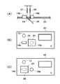
図1及び図2には、参考例に係る電子内視鏡装置の構成が示されており、この参考例は、可動遮蔽体をスライド自在にするコネクタ受け開閉機構を用いたものである。図2において、電子内視鏡装置は、例えばAタイプの電子内視鏡(スコープ)1Aと、Bタイプの電子内視鏡1Bを有し、これらをプロセッサ装置12に接続できるように構成される。なお、プロセッサ装置12では、光源部が内蔵されているが、光源装置が別体で設けられているものもある。1 and 2, a configuration is shown in the electronic endoscope apparatus according to areference example, thisreference example is obtained by using a connector receiving opening and closing mechanism to slidably movable shield. In FIG. 2, the electronic endoscope apparatus includes, for example, an A type electronic endoscope (scope) 1 </ b> A and a B type
図1において、プロセッサ装置12には、各種の電子内視鏡1A,1Bの光源コネクタ3を接続するコネクタ受け13が設けられると共に、Aタイプの電子内視鏡1Aの電気コネクタ14aを接続する角形コネクタ受け14bと、Bタイプの電子内視鏡1Bの電気コネクタ15aを接続する丸形コネクタ受け15bが設けられる。そして、ツマミ17を表面側に取り付けた平板の遮蔽体(蓋体)18と、この遮蔽体18を上下で保持した状態でコネクタ受け14b及び15bの差込口(前面)側をスライドさせる上下レール19とが設けられ、この上下レール19の端部には、レール部材を上下レール間中央側へ折り曲げた係止部(ストッパ)20が形成される。In FIG. 1, the
このような参考例によれば、図1(A)に示されるように、ツマミ17によって遮蔽体18を図の左側へ移動させ、係止部20へ当たるまでスライドさせれば、コネクタ受け(差込口)14bが閉塞され(閉となり)、コネクタ受け15bが露出される(開となる)ことになり、このコネクタ受け15bに、Bタイプの電子内視鏡1Bのコネクタ15aを接続することができる。一方、図1(B)に示されるように、遮蔽体18を図の右側へスライド移動させれば、コネクタ受け(差込口)15bが閉塞され、コネクタ受け14bが露出され、図2に示されるように、このコネクタ受け14bに、Aタイプの電子内視鏡1Aのコネクタ14aを接続できることになる。なお、上記上下レール19の係止部20は、遮蔽体18の停止位置を案内すると共に、遮蔽体18の脱落を防止する役目をする。According to such areference example, as shown in FIG. 1A, when the
このようにして、参考例のコネクタ受け開閉機構によれば、コネクタ受け14bと15bの一方が選択的に露出され、そのとき他方は閉塞されることになるので、コネクタ受け14b,15bへの水分等の浸入が確実に防止される。なお、この例では、2つのコネクタ受け14b,15bが配置されている場合を説明したが、3つ以上のn個のコネクタ受けが配置されている場合は、n−1個の独立した遮蔽体をスライド自在に配置することにより、使用する1つのコネクタ受けを露出させ、その他の不使用のコネクタ受けを閉塞することが可能になる。In this way, according to the connector receiver opening / closing mechanism of thereference example, one of the
図3には、第1実施例に係る電子内視鏡装置のプロセッサ装置の構成が示されており、この第1実施例は、可動遮蔽体を回転軸により揺動自在にするコネクタ受け開閉機構を用いたものである。図3において、プロセッサ装置22には、コネクタ受け14bと15bとの中間点に回転軸24が配置され、この回転軸24を中心として回転揺動する平板の揺動遮蔽体25が設けられる。また、この揺動遮蔽体25には、この揺動遮蔽体25をコネクタ受け14b側へ引っ張る付勢部材(スプリング等)27と、揺動遮蔽体25をコネクタ受け15b側へ引っ張る付勢部材28とが配置される。FIG. 3 arrangement is shown of the processor unit of an electronic endoscope apparatus according to afirst embodiment, thefirst embodiment, the connector is swingable by a rotary shaft of the movable shield receiving opening and closing mechanism Is used. In FIG. 3, the
このような第1実施例によれば、図3(A),(B)に示されるように、揺動遮蔽体25を図の右側へ揺動させると、付勢部材28が揺動遮蔽体25をコネクタ受け15b側へ引っ張ることにより、この揺動遮蔽体25がコネクタ受け(差込口)15bを閉塞し、コネクタ受け14bが露出される。一方、揺動遮蔽体25を図の左側へ揺動させると、付勢部材27が揺動遮蔽体25をコネクタ受け14b側へ引っ張ることにより、図3(C)に示されるように、揺動遮蔽体25がコネクタ受け(差込口)14bを閉塞し、コネクタ受け15bが露出される。According to such afirst embodiment, as shown in FIGS. 3A and 3B, when the
図4には、第2実施例の電子内視鏡装置のコネクタ受け開閉機構の構成が示されており、この第2実施例は、各コネクタ受けの差込口側に配置した2つの可動遮蔽体を選択的に開閉するものである。図4において、プロセッサ装置12には、コネクタ受け14bの差込口側(前面)を塞いだ位置から上へ移動するように案内された平板の遮蔽体30、コネクタ受け15bの差込口側を塞いだ位置から上へ移動するように案内された平板の遮蔽体31が設けられ、これら遮蔽体30と31の連結開閉機構として、遮蔽体30にラック32、遮蔽体31にラック33が取り付けられ、かつこれらラック32とラック33との間にピニオン34が噛合配置される。なお、上記遮蔽体30と31の下側には、前側へ突出する突起で、指を載置するための操作突起部35が形成される。Figure 4, and configuration of the connector receiving opening and closing mechanism of the electronic endoscope apparatus of thesecond embodiment is shown, thesecond embodiment, two movable shields placed on outlet side of each connector receiver It opens and closes the body selectively. In FIG. 4, the
このような第2実施例によれば、図4(A)の状態から操作突起部35で遮蔽体31を図の下側へ押し下げると、ラック33、ピニオン34及びラック32を介して遮蔽体30が上昇し、図4(B)の状態となり、コネクタ受け15bが閉塞してコネクタ受け14bが露出される。一方、図4(B)の状態から操作突起部35で遮蔽体30を図の下側へ押し下げると、ラック32、ピニオン34及びラック33を介して遮蔽体31が上昇し、図4(A)の状態となり、コネクタ受け14bが閉塞してコネクタ受け15bが露出される。そして、図4(A)のように露出したコネクタ受け15bにBタイプの電子内視鏡1Bのコネクタ15aが接続され、図4(B)のように露出したコネクタ受け14bにAタイプの電子内視鏡1Aのコネクタ14aが接続される。According to thesecond embodiment, when the
なお、この第2実施例では、連結開閉機構の構成にラック32,33とピニオン34を用いたが、この連結開閉機構にリンク機構等を利用してもよいし、また遮蔽体30,31を1枚の板状体としたが、コネクタ受け14b,15bのそれぞれの遮蔽体として、2枚以上の小遮蔽体を開閉動作させるような遮蔽構造を用いてもよい。In thesecond embodiment, the
図5には、第3実施例のコネクタ受け開閉機構の構成が示されており、この第3実施例は、各コネクタ受けの前面側に配置した2つの可動遮蔽体を全閉状態とし、この状態から1つの可動遮蔽体を選択的に開閉するものである。図5において、プロセッサ装置12には、コネクタ受け14bの差込口側を塞いだ位置から上へ移動するようにガイドされた平板の遮蔽体38、コネクタ受け15bの差込口側を塞いだ位置から上へ移動するようにガイドされた平板の遮蔽体39が設けられ、これら遮蔽体38と39の連結開閉機構として、水平方向で左右に往復動する往復動ストッパ40と、遮蔽体38側の誘導体(作動体)41及び遮蔽体39側の誘導体42が設けられる。5 shows, thethird is shown the configuration of an embodiment of the connector receiving opening and closing mechanism, thethird embodiment, the two movable shields placed on the front side of each connector receiver is fully closed, the One movable shield is selectively opened and closed from the state. In FIG. 5, the
上記往復動ストッパ40は、その本体に形成された案内溝43とこの案内溝43に係合する2つのピン44によって左右に往復動し、この往復動ストッパ40の左右端には、下側をカットした下向き斜面40sが設けられる。一方、上記誘導体41と42には、往復動ストッパ40の左右の下向き斜面40sに当接する(下向き斜面40sの傾斜角度に合わせた傾斜角度の斜面を有し、この斜面40sに接触する)上向き斜面41sと42sが形成される。なお、遮蔽体38と39の下側には、前側へ突出する突起で、指を載置するための操作突起部45が設けられる。 The reciprocating
このような第3実施例によれば、装置の不使用時には、図5(A)に示されるように、遮蔽体38,39によって、両方のコネクタ受け14b,15bが閉塞され、全閉状態となっている。そして、Aタイプの電子内視鏡1Aを使用する場合は、図5(A)の状態から、図5(B)に示されるように、遮蔽体38を操作突起部45によって図の上側へ押し上げると、誘導体41の上向き斜面41sが下向き斜面40sを押すことにより往復動ストッパ40を右側へ移動させ、遮蔽体38の側面が往復動ストッパ40の側面に当接した状態となり、コネクタ受け14bが露出され、開状態となる。このとき、往復動ストッパ40は左側への移動が規制されると共に、往復動ストッパ40の右側の下向き斜面40sが上向き斜面42sに当接するため、遮蔽体39の上側への移動ができなくなってロックされる。その後、この電子内視鏡1Aの使用が終了したときには、コネクタ受け14bからコネクタ14aを抜き、遮蔽体38を押し下げれば、図5(A)の状態に戻ることになる。According to thethird embodiment, when the apparatus is not used, as shown in FIG. 5A, both the
一方、Bタイプの電子内視鏡1Bを使用する場合は、図5(A)の状態から、図5(C)に示されるように、遮蔽体39を操作突起部45によって図の上側へ押し上げると、誘導体42の上向き斜面42sが下向き斜面40sを押すことにより往復動ストッパ40を左側へ移動させ、遮蔽体39の側面が往復動ストッパ40の側面に当接した状態となり、コネクタ受け15bが露出され、開状態となる。このとき、往復動ストッパ40は右側への移動が規制されると共に、往復動ストッパ40の左側の下向き斜面40sが上向き斜面41sに当接するため、遮蔽体38の上側への移動ができなくなってロックされる。 On the other hand, when the B type
なお、この第3実施例では、遮蔽体38,39の一方が上側へ押し上げられ、開状態となっているとき、その開状態を維持するための係止手段(凹凸部嵌合部材等)を設けてもよい。
また、第2実施例、第3実施例のコネクタ受け開閉機構をコネクタ受けが3つ以上配置されたプロセッサ装置に応用することもできる。In thisthird embodiment, when one of the
It is also possible to apply to thesecond embodiment, a processor device receiving connector a connector receiving opening and closing mechanism of thethird embodiment is disposed three or more.
1A…Aタイプの電子内視鏡、 1B…Bタイプの電子内視鏡、
4a,14a,5a,15a…コネクタ、
4b,14b,5b,15b…コネクタ受け、
2,12,22…プロセッサ装置、
18,30,31,38,39…遮蔽体、
19…上下レール、 20…係止部、
24…回転軸、 25…揺動遮蔽体、
32,33…ラック、 34…ピニオン、
40…往復動ストッパ、 41,42…誘導体、
40s,41s,42s…斜面。1A ... A type electronic endoscope, 1B ... B type electronic endoscope,
4a, 14a, 5a, 15a ... connectors,
4b, 14b, 5b, 15b ... connector receptacle,
2, 12, 22 ... processor device,
18, 30, 31, 38, 39 ... shields,
19 ... Upper and lower rails, 20 ... Locking parts,
24 ... Rotating
32, 33 ... rack, 34 ... pinion,
40:
40s, 41s, 42s ... slopes.
Claims (3)
Translated fromJapanese使用する電子内視鏡に対応して上記複数のコネクタ受けを露出状態と閉塞状態に設定するため、回転軸により揺動自在とされた可動遮蔽体を有し、この可動遮蔽体が揺動して一方のコネクタ受けを露出させたとき、揺動した可動遮蔽体で他方のコネクタ受けを閉塞するように動作するコネクタ受け開閉機構を設けたことを特徴とする電子内視鏡装置。An electronic endoscope apparatus having a plurality of connector receivers for connecting electrical connectors of various electronic endoscopes and provided with a processor device that performs video processing on a video signal output from the electronic endoscope In
Inorder to set theplurality of connector receivers in an exposed state and a closed statecorresponding to the electronic endoscopeto be used, a movable shield that can be swung by a rotating shaft is provided, and the movable shield is swung. An electronic endoscope apparatus comprisinga connector receiver opening / closing mechanism thatoperates to close the other connector receiver with a swingable movable shield when one connector receiver is exposed .
使用する電子内視鏡に対応して上記複数のコネクタ受けを露出状態と閉塞状態に設定するため、各コネクタ受けの差込口側にそれぞれの可動遮蔽体を配置すると共に、これらの可動遮蔽体を連結する機構であって、一方のコネクタ受けの可動遮蔽体がそのコネクタ受けを露出させたとき、他方のコネクタ受けの可動遮蔽体がそのコネクタ受けを閉塞する遮蔽体連結開閉機構を設けたコネクタ受け開閉機構を備えたことを特徴とする電子内視鏡装置。An electronic endoscope apparatus having a plurality of connector receivers for connecting electrical connectors of various electronic endoscopes and provided with a processor device that performs video processing on a video signal output from the electronic endoscope In
In order to set the plurality of connector receivers in an exposed state and a closed state corresponding to the electronic endoscope to be used, each movable shield is disposed on the insertion port side of each connector receiver, and these movable shields A connector provided with a shield connection opening / closing mechanism that, when the movable shield of one connector receiver exposes the connector receiver, the movable shield of the other connector receiver closes the connector receiver. An electronic endoscope apparatus comprisinga receiving opening / closing mechanism .
使用する電子内視鏡に対応して上記複数のコネクタ受けを露出状態と閉塞状態に設定するため、各コネクタ受けの差込口側にそれぞれの可動遮蔽体を配置すると共に、これらの可動遮蔽体を連結する機構であって、全ての可動遮蔽体が全てのコネクタ受けを閉塞状態とし、一方のコネクタ受けの可動遮蔽体がそのコネクタ受けを露出させたとき、他方のコネクタ受けの可動遮蔽体の閉塞状態をロックする全閉式遮蔽体連結開閉機構を設けたコネクタ受け開閉機構を備えたことを特徴とする電子内視鏡装置。An electronic endoscope apparatus having a plurality of connector receivers for connecting electrical connectors of various electronic endoscopes and provided with a processor device that performs video processing on a video signal output from the electronic endoscope In
In order to set the plurality of connector receivers in an exposed state and a closed state corresponding to the electronic endoscope to be used, each movable shield is disposed on the insertion port side of each connector receiver, and these movable shields When all the movable shields close all the connector receptacles and the movable shield of one connector receptacle exposes the connector receptacle, the movable shield of the other connector receptacle An electronic endoscope apparatus comprisinga connector receiver opening / closing mechanism provided with a fully-closed shield connection opening / closing mechanism for locking a closed state .
Priority Applications (1)
| Application Number | Priority Date | Filing Date | Title |
|---|---|---|---|
| JP2007075935AJP4928320B2 (en) | 2007-03-23 | 2007-03-23 | Electronic endoscope device |
Applications Claiming Priority (1)
| Application Number | Priority Date | Filing Date | Title |
|---|---|---|---|
| JP2007075935AJP4928320B2 (en) | 2007-03-23 | 2007-03-23 | Electronic endoscope device |
Publications (2)
| Publication Number | Publication Date |
|---|---|
| JP2008229204A JP2008229204A (en) | 2008-10-02 |
| JP4928320B2true JP4928320B2 (en) | 2012-05-09 |
Family
ID=39902705
Family Applications (1)
| Application Number | Title | Priority Date | Filing Date |
|---|---|---|---|
| JP2007075935AExpired - Fee RelatedJP4928320B2 (en) | 2007-03-23 | 2007-03-23 | Electronic endoscope device |
Country Status (1)
| Country | Link |
|---|---|
| JP (1) | JP4928320B2 (en) |
Families Citing this family (32)
| Publication number | Priority date | Publication date | Assignee | Title |
|---|---|---|---|---|
| US9901244B2 (en) | 2009-06-18 | 2018-02-27 | Endochoice, Inc. | Circuit board assembly of a multiple viewing elements endoscope |
| US9713417B2 (en) | 2009-06-18 | 2017-07-25 | Endochoice, Inc. | Image capture assembly for use in a multi-viewing elements endoscope |
| US12137873B2 (en) | 2009-06-18 | 2024-11-12 | Endochoice, Inc. | Compact multi-viewing element endoscope system |
| US9492063B2 (en) | 2009-06-18 | 2016-11-15 | Endochoice Innovation Center Ltd. | Multi-viewing element endoscope |
| US9706903B2 (en) | 2009-06-18 | 2017-07-18 | Endochoice, Inc. | Multiple viewing elements endoscope system with modular imaging units |
| US9101287B2 (en) | 2011-03-07 | 2015-08-11 | Endochoice Innovation Center Ltd. | Multi camera endoscope assembly having multiple working channels |
| US9402533B2 (en) | 2011-03-07 | 2016-08-02 | Endochoice Innovation Center Ltd. | Endoscope circuit board assembly |
| US10165929B2 (en) | 2009-06-18 | 2019-01-01 | Endochoice, Inc. | Compact multi-viewing element endoscope system |
| US11547275B2 (en) | 2009-06-18 | 2023-01-10 | Endochoice, Inc. | Compact multi-viewing element endoscope system |
| US9642513B2 (en) | 2009-06-18 | 2017-05-09 | Endochoice Inc. | Compact multi-viewing element endoscope system |
| US11278190B2 (en) | 2009-06-18 | 2022-03-22 | Endochoice, Inc. | Multi-viewing element endoscope |
| US9101268B2 (en) | 2009-06-18 | 2015-08-11 | Endochoice Innovation Center Ltd. | Multi-camera endoscope |
| US11864734B2 (en) | 2009-06-18 | 2024-01-09 | Endochoice, Inc. | Multi-camera endoscope |
| WO2010146587A1 (en) | 2009-06-18 | 2010-12-23 | Peer Medical Ltd. | Multi-camera endoscope |
| US8926502B2 (en) | 2011-03-07 | 2015-01-06 | Endochoice, Inc. | Multi camera endoscope having a side service channel |
| US9872609B2 (en) | 2009-06-18 | 2018-01-23 | Endochoice Innovation Center Ltd. | Multi-camera endoscope |
| US12220105B2 (en) | 2010-06-16 | 2025-02-11 | Endochoice, Inc. | Circuit board assembly of a multiple viewing elements endoscope |
| EP2618718B1 (en) | 2010-09-20 | 2020-04-15 | EndoChoice Innovation Center Ltd. | Multi-camera endoscope having fluid channels |
| US9560953B2 (en) | 2010-09-20 | 2017-02-07 | Endochoice, Inc. | Operational interface in a multi-viewing element endoscope |
| CN103403605A (en) | 2010-10-28 | 2013-11-20 | 恩多巧爱思创新中心有限公司 | Optical systems for multi-sensor endoscopes |
| US12204087B2 (en) | 2010-10-28 | 2025-01-21 | Endochoice, Inc. | Optical systems for multi-sensor endoscopes |
| US11889986B2 (en) | 2010-12-09 | 2024-02-06 | Endochoice, Inc. | Flexible electronic circuit board for a multi-camera endoscope |
| US9320419B2 (en) | 2010-12-09 | 2016-04-26 | Endochoice Innovation Center Ltd. | Fluid channeling component of a multi-camera endoscope |
| CN107361721B (en) | 2010-12-09 | 2019-06-18 | 恩多巧爱思创新中心有限公司 | Flexible electronic circuit boards for multi-camera endoscopes |
| EP2672878B1 (en) | 2011-02-07 | 2017-11-22 | Endochoice Innovation Center Ltd. | Multi-element cover for a multi-camera endoscope |
| CA2798716A1 (en) | 2011-12-13 | 2013-06-13 | Peermedical Ltd. | Removable tip endoscope |
| EP2604172B1 (en) | 2011-12-13 | 2015-08-12 | EndoChoice Innovation Center Ltd. | Rotatable connector for an endoscope |
| US9560954B2 (en) | 2012-07-24 | 2017-02-07 | Endochoice, Inc. | Connector for use with endoscope |
| US9986899B2 (en) | 2013-03-28 | 2018-06-05 | Endochoice, Inc. | Manifold for a multiple viewing elements endoscope |
| US9993142B2 (en) | 2013-03-28 | 2018-06-12 | Endochoice, Inc. | Fluid distribution device for a multiple viewing elements endoscope |
| US10499794B2 (en) | 2013-05-09 | 2019-12-10 | Endochoice, Inc. | Operational interface in a multi-viewing element endoscope |
| JP6872575B2 (en) | 2019-02-27 | 2021-05-19 | Hoya株式会社 | Endoscope processor and endoscopic system |
Family Cites Families (5)
| Publication number | Priority date | Publication date | Assignee | Title |
|---|---|---|---|---|
| JPH02158068A (en)* | 1988-12-12 | 1990-06-18 | Pfu Ltd | Connector mounting structure |
| JPH0982079A (en)* | 1995-07-10 | 1997-03-28 | Fujitsu Ltd | Optical storage |
| JPH09308606A (en)* | 1996-05-23 | 1997-12-02 | Asahi Optical Co Ltd | Video processor for electronic endoscope |
| JP2004070639A (en)* | 2002-08-06 | 2004-03-04 | Y E Data Inc | Multi-memory card reader |
| JP2004236738A (en)* | 2003-02-04 | 2004-08-26 | Fuji Photo Optical Co Ltd | Processor for electronic endoscope |
- 2007
- 2007-03-23JPJP2007075935Apatent/JP4928320B2/ennot_activeExpired - Fee Related
Also Published As
| Publication number | Publication date |
|---|---|
| JP2008229204A (en) | 2008-10-02 |
Similar Documents
| Publication | Publication Date | Title |
|---|---|---|
| JP4928320B2 (en) | Electronic endoscope device | |
| CN105358043B (en) | The white balance shell being used together with more observation element endoscopes | |
| DE19815637B4 (en) | Dental x-ray image detection device and adapter therefor | |
| DE102008026392A1 (en) | Endoscope with focal length modification function | |
| EP1262751B1 (en) | Apparatus and method for analysing light | |
| DE102004042332A1 (en) | capsule endoscope | |
| DE112009005278B4 (en) | Portable computer with a tilting camera arrangement | |
| US10094455B2 (en) | Multipurpose opening and closing device | |
| EP1610685A1 (en) | X-ray device and x-ray sensitive camera for panoramic tomography and 3d shots | |
| EP1613218A1 (en) | X-ray sensitive camera comprising two image receivers and x-ray device | |
| DE19846888A1 (en) | Mounting arrangement of video camera for projection display | |
| US20180000323A1 (en) | Endoscope apparatus and light source apparatus | |
| JP2007181700A (en) | In-vivo imaging optical device | |
| US20200260936A1 (en) | Light source apparatus for endoscope | |
| JP2010145652A (en) | Lens cover mechanism and imaging apparatus | |
| CN201139551Y (en) | Tongue state capturing dark box | |
| EP3934506A1 (en) | Endoscope with light-emitting device and image capturing device on the distal end portion | |
| CN112470056B (en) | Processor for endoscope and endoscope system | |
| CN104808330A (en) | Portable optical instrument and image pickup apparatus | |
| JP2007014591A (en) | Opening/closing mechanism of large winning hole of game machine | |
| US7542094B2 (en) | Adapter device | |
| JP2009142371A (en) | Electronic endoscope apparatus | |
| JP5631647B2 (en) | Electronics | |
| JP2002028335A (en) | Game machine control device | |
| JP4334846B2 (en) | Stereoscopic imaging device |
Legal Events
| Date | Code | Title | Description |
|---|---|---|---|
| A621 | Written request for application examination | Free format text:JAPANESE INTERMEDIATE CODE: A621 Effective date:20090917 | |
| A711 | Notification of change in applicant | Free format text:JAPANESE INTERMEDIATE CODE: A711 Effective date:20090917 | |
| RD02 | Notification of acceptance of power of attorney | Free format text:JAPANESE INTERMEDIATE CODE: A7422 Effective date:20090917 | |
| A521 | Written amendment | Free format text:JAPANESE INTERMEDIATE CODE: A821 Effective date:20090917 | |
| A977 | Report on retrieval | Free format text:JAPANESE INTERMEDIATE CODE: A971007 Effective date:20111124 | |
| A131 | Notification of reasons for refusal | Free format text:JAPANESE INTERMEDIATE CODE: A131 Effective date:20111129 | |
| A521 | Written amendment | Free format text:JAPANESE INTERMEDIATE CODE: A523 Effective date:20120123 | |
| TRDD | Decision of grant or rejection written | ||
| A01 | Written decision to grant a patent or to grant a registration (utility model) | Free format text:JAPANESE INTERMEDIATE CODE: A01 Effective date:20120207 | |
| A01 | Written decision to grant a patent or to grant a registration (utility model) | Free format text:JAPANESE INTERMEDIATE CODE: A01 | |
| A61 | First payment of annual fees (during grant procedure) | Free format text:JAPANESE INTERMEDIATE CODE: A61 Effective date:20120210 | |
| FPAY | Renewal fee payment (event date is renewal date of database) | Free format text:PAYMENT UNTIL: 20150217 Year of fee payment:3 | |
| R150 | Certificate of patent or registration of utility model | Free format text:JAPANESE INTERMEDIATE CODE: R150 | |
| LAPS | Cancellation because of no payment of annual fees |