JP4924750B2 - Power converter - Google Patents
Power converterDownload PDFInfo
- Publication number
- JP4924750B2 JP4924750B2JP2010244596AJP2010244596AJP4924750B2JP 4924750 B2JP4924750 B2JP 4924750B2JP 2010244596 AJP2010244596 AJP 2010244596AJP 2010244596 AJP2010244596 AJP 2010244596AJP 4924750 B2JP4924750 B2JP 4924750B2
- Authority
- JP
- Japan
- Prior art keywords
- wall portion
- frame
- front wall
- case
- power conversion
- Prior art date
- Legal status (The legal status is an assumption and is not a legal conclusion. Google has not performed a legal analysis and makes no representation as to the accuracy of the status listed.)
- Active
Links
- 239000003507refrigerantSubstances0.000claimsdescription171
- 238000006243chemical reactionMethods0.000claimsdescription106
- 239000004065semiconductorSubstances0.000claimsdescription64
- 238000001816coolingMethods0.000claimsdescription40
- 238000012856packingMethods0.000claimsdescription28
- 239000002826coolantSubstances0.000claimsdescription15
- 230000015572biosynthetic processEffects0.000claimsdescription12
- 238000010030laminatingMethods0.000claimsdescription8
- 238000007599dischargingMethods0.000claimsdescription5
- 230000002265preventionEffects0.000claims1
- 239000003990capacitorSubstances0.000description49
- 238000003825pressingMethods0.000description15
- 239000003566sealing materialSubstances0.000description9
- 230000000694effectsEffects0.000description8
- 239000004020conductorSubstances0.000description7
- 238000012423maintenanceMethods0.000description7
- 238000007789sealingMethods0.000description7
- 239000000758substrateSubstances0.000description6
- 238000004519manufacturing processMethods0.000description5
- 239000000463materialSubstances0.000description5
- XLYOFNOQVPJJNP-UHFFFAOYSA-NwaterSubstancesOXLYOFNOQVPJJNP-UHFFFAOYSA-N0.000description5
- XEEYBQQBJWHFJM-UHFFFAOYSA-NIronChemical compound[Fe]XEEYBQQBJWHFJM-UHFFFAOYSA-N0.000description4
- 239000011347resinSubstances0.000description4
- 229920005989resinPolymers0.000description4
- LYCAIKOWRPUZTN-UHFFFAOYSA-NEthylene glycolChemical compoundOCCOLYCAIKOWRPUZTN-UHFFFAOYSA-N0.000description3
- OKKJLVBELUTLKV-UHFFFAOYSA-NMethanolChemical compoundOCOKKJLVBELUTLKV-UHFFFAOYSA-N0.000description3
- 230000002452interceptive effectEffects0.000description3
- 230000003014reinforcing effectEffects0.000description3
- 230000008646thermal stressEffects0.000description3
- CSCPPACGZOOCGX-UHFFFAOYSA-NAcetoneChemical compoundCC(C)=OCSCPPACGZOOCGX-UHFFFAOYSA-N0.000description2
- QGZKDVFQNNGYKY-UHFFFAOYSA-NAmmoniaChemical compoundNQGZKDVFQNNGYKY-UHFFFAOYSA-N0.000description2
- LFQSCWFLJHTTHZ-UHFFFAOYSA-NEthanolChemical compoundCCOLFQSCWFLJHTTHZ-UHFFFAOYSA-N0.000description2
- 239000000956alloySubstances0.000description2
- 229910045601alloyInorganic materials0.000description2
- 229910052782aluminiumInorganic materials0.000description2
- XAGFODPZIPBFFR-UHFFFAOYSA-NaluminiumChemical compound[Al]XAGFODPZIPBFFR-UHFFFAOYSA-N0.000description2
- 238000005553drillingMethods0.000description2
- 238000003780insertionMethods0.000description2
- 230000037431insertionEffects0.000description2
- 229910052742ironInorganic materials0.000description2
- 229910052751metalInorganic materials0.000description2
- 239000002184metalSubstances0.000description2
- 238000000034methodMethods0.000description2
- 238000000465mouldingMethods0.000description2
- 238000005498polishingMethods0.000description2
- 230000009466transformationEffects0.000description2
- OHMHBGPWCHTMQE-UHFFFAOYSA-N2,2-dichloro-1,1,1-trifluoroethaneChemical compoundFC(F)(F)C(Cl)ClOHMHBGPWCHTMQE-UHFFFAOYSA-N0.000description1
- 150000001298alcoholsChemical class0.000description1
- 229910021529ammoniaInorganic materials0.000description1
- 230000002528anti-freezeEffects0.000description1
- 230000005540biological transmissionEffects0.000description1
- KYKAJFCTULSVSH-UHFFFAOYSA-Nchloro(fluoro)methaneChemical compoundF[C]ClKYKAJFCTULSVSH-UHFFFAOYSA-N0.000description1
- 238000013461designMethods0.000description1
- 230000005669field effectEffects0.000description1
- NBVXSUQYWXRMNV-UHFFFAOYSA-NfluoromethaneChemical compoundFCNBVXSUQYWXRMNV-UHFFFAOYSA-N0.000description1
- 230000014509gene expressionEffects0.000description1
- 150000002576ketonesChemical class0.000description1
- 238000003475laminationMethods0.000description1
- 239000000565sealantSubstances0.000description1
- 239000013585weight reducing agentSubstances0.000description1
Images


Classifications
- H—ELECTRICITY
- H05—ELECTRIC TECHNIQUES NOT OTHERWISE PROVIDED FOR
- H05K—PRINTED CIRCUITS; CASINGS OR CONSTRUCTIONAL DETAILS OF ELECTRIC APPARATUS; MANUFACTURE OF ASSEMBLAGES OF ELECTRICAL COMPONENTS
- H05K7/00—Constructional details common to different types of electric apparatus
- H05K7/20—Modifications to facilitate cooling, ventilating, or heating
- H05K7/20845—Modifications to facilitate cooling, ventilating, or heating for automotive electronic casings
- H05K7/20854—Heat transfer by conduction from internal heat source to heat radiating structure
- H—ELECTRICITY
- H01—ELECTRIC ELEMENTS
- H01L—SEMICONDUCTOR DEVICES NOT COVERED BY CLASS H10
- H01L23/00—Details of semiconductor or other solid state devices
- H01L23/34—Arrangements for cooling, heating, ventilating or temperature compensation ; Temperature sensing arrangements
- H01L23/40—Mountings or securing means for detachable cooling or heating arrangements ; fixed by friction, plugs or springs
- H01L23/4006—Mountings or securing means for detachable cooling or heating arrangements ; fixed by friction, plugs or springs with bolts or screws
- H01L23/4012—Mountings or securing means for detachable cooling or heating arrangements ; fixed by friction, plugs or springs with bolts or screws for stacked arrangements of a plurality of semiconductor devices
- H—ELECTRICITY
- H01—ELECTRIC ELEMENTS
- H01L—SEMICONDUCTOR DEVICES NOT COVERED BY CLASS H10
- H01L23/00—Details of semiconductor or other solid state devices
- H01L23/34—Arrangements for cooling, heating, ventilating or temperature compensation ; Temperature sensing arrangements
- H01L23/40—Mountings or securing means for detachable cooling or heating arrangements ; fixed by friction, plugs or springs
- H01L23/4093—Snap-on arrangements, e.g. clips
- H—ELECTRICITY
- H01—ELECTRIC ELEMENTS
- H01L—SEMICONDUCTOR DEVICES NOT COVERED BY CLASS H10
- H01L23/00—Details of semiconductor or other solid state devices
- H01L23/34—Arrangements for cooling, heating, ventilating or temperature compensation ; Temperature sensing arrangements
- H01L23/46—Arrangements for cooling, heating, ventilating or temperature compensation ; Temperature sensing arrangements involving the transfer of heat by flowing fluids
- H01L23/473—Arrangements for cooling, heating, ventilating or temperature compensation ; Temperature sensing arrangements involving the transfer of heat by flowing fluids by flowing liquids
- H—ELECTRICITY
- H05—ELECTRIC TECHNIQUES NOT OTHERWISE PROVIDED FOR
- H05K—PRINTED CIRCUITS; CASINGS OR CONSTRUCTIONAL DETAILS OF ELECTRIC APPARATUS; MANUFACTURE OF ASSEMBLAGES OF ELECTRICAL COMPONENTS
- H05K7/00—Constructional details common to different types of electric apparatus
- H05K7/20—Modifications to facilitate cooling, ventilating, or heating
- H05K7/2089—Modifications to facilitate cooling, ventilating, or heating for power electronics, e.g. for inverters for controlling motor
- H05K7/20927—Liquid coolant without phase change
- H—ELECTRICITY
- H01—ELECTRIC ELEMENTS
- H01L—SEMICONDUCTOR DEVICES NOT COVERED BY CLASS H10
- H01L2924/00—Indexing scheme for arrangements or methods for connecting or disconnecting semiconductor or solid-state bodies as covered by H01L24/00
- H01L2924/0001—Technical content checked by a classifier
- H01L2924/0002—Not covered by any one of groups H01L24/00, H01L24/00 and H01L2224/00
- H—ELECTRICITY
- H02—GENERATION; CONVERSION OR DISTRIBUTION OF ELECTRIC POWER
- H02M—APPARATUS FOR CONVERSION BETWEEN AC AND AC, BETWEEN AC AND DC, OR BETWEEN DC AND DC, AND FOR USE WITH MAINS OR SIMILAR POWER SUPPLY SYSTEMS; CONVERSION OF DC OR AC INPUT POWER INTO SURGE OUTPUT POWER; CONTROL OR REGULATION THEREOF
- H02M7/00—Conversion of AC power input into DC power output; Conversion of DC power input into AC power output
- H02M7/003—Constructional details, e.g. physical layout, assembly, wiring or busbar connections
Landscapes
- Engineering & Computer Science (AREA)
- Microelectronics & Electronic Packaging (AREA)
- Physics & Mathematics (AREA)
- Condensed Matter Physics & Semiconductors (AREA)
- General Physics & Mathematics (AREA)
- Computer Hardware Design (AREA)
- Power Engineering (AREA)
- Thermal Sciences (AREA)
- Inverter Devices (AREA)
- Dc-Dc Converters (AREA)
Description
Translated fromJapanese本発明は、電力変換回路を構成する複数の電子部品と、少なくとも一部の上記電子部品を冷却する冷却器とを、ケース内に収容してなる電力変換装置に関する。 The present invention relates to a power conversion device in which a plurality of electronic components constituting a power conversion circuit and a cooler for cooling at least some of the electronic components are accommodated in a case.
例えば、電気自動車やハイブリッド自動車等には、電源電力から駆動用モータを駆動するための駆動用電力に変換するためのインバータやコンバータ等の電力変換装置が搭載されている。図41に示すごとく、かかる電力変換装置9は、スイッチング素子を内蔵した半導体モジュール921やコンデンサ922を始めとして、電力変換回路を構成する各種電子部品を備えている(特許文献1参照)。また、半導体モジュール921の温度上昇を抑制するために、これらを冷却する冷却器93が半導体モジュール921に接触配置されている。 For example, electric vehicles, hybrid vehicles, and the like are equipped with power conversion devices such as inverters and converters for converting power supply power into drive power for driving a drive motor. As shown in FIG. 41, the
さらには、電力変換装置9は、半導体モジュール921を制御する制御回路が形成された制御回路基板96をも備えている。
そして、これらの半導体モジュール921等の電子部品、冷却器93、制御回路基板96は、ケース94に固定され、ケース94内に密封されている。Furthermore, the
The electronic components such as the
しかしながら、ケース94の剛性が充分に高くないと、ケース94に固定された電子部品が大きく振動して断線等の原因となったり、外力が内部の電子部品等に加わって故障の原因となったりするなどの不具合が発生しやすい。 However, if the rigidity of the
また、電力変換装置9は、エンジンルームなどに配置されることがあるが、この場合、急激な温度変化に伴って、ケース94が熱膨張あるいは熱収縮することがある。このとき、ケース94に直接、各種部品が組み付けられていると、これらの部品に熱応力が加わり、故障の原因を招くおそれがある。 The
また、特許文献1に記載の電力変換装置9は、ケース94を、ケース本体940とその両側に設けた下蓋941と上蓋942とによって構成してある。そのため、ケース94には、二か所の大きなシール面が形成され、これら2つのシール面の水密性を確保する必要がある。それゆえ、シール材を多く形成する必要があり、コスト面においても、製造面においても、不利となりやすい。 Further, in the
また、メンテナンスの際には、下蓋941と上蓋942とを取り外す必要があるため、メンテナンスの作業性も高いとは言い難い。
仮に、単に下蓋941を廃止して、ケース94を、底部のあるケース本体と上蓋とによって構成すれば、シール面を一つにできるが、この場合は、メンテナンス性がさらに低下することとなるし、ケース94の剛性がさらに低下することにもなる。Further, since it is necessary to remove the
If the
また、ケース94に直接コンデンサ922等の電子部品を固定すると、その振動がケース94を通じて車体等に伝わり、不快な振動音が車内に伝わるなどの不具合も生じやすい。逆に、エンジンの振動が、ケース94を通じて電子部品に伝わって、断線や故障の原因となるおそれもある。 Further, when an electronic component such as the
また、電力変換装置を搭載する車種によって、被搭載部(エンジンルーム等)の形状や構造が異なると、それに応じて電力変換装置における外部レイアウトとの接続位置を変更するなど、その形状を車種ごとに変更する必要がある。かかる観点において、ケースに各種電子部品及び冷却器を直接組み付ける構造の電力変換装置においては、ケースのみならずその内部のレイアウトをも変更する必要が生じる。その結果、車種ごとに設計変更を余儀なくされ、生産性を向上させ難く、低コスト化の阻害要因ともなる。 Also, if the shape or structure of the mounted part (engine room, etc.) differs depending on the vehicle model on which the power converter is mounted, the connection position with the external layout in the power converter is changed accordingly. It is necessary to change to. From this point of view, in a power conversion device having a structure in which various electronic components and a cooler are directly assembled to a case, it is necessary to change not only the case but also its internal layout. As a result, it is necessary to change the design for each vehicle type, it is difficult to improve productivity, and it becomes an impediment to cost reduction.
また、冷却器93は、該冷却器93へ冷却媒体を導入する冷媒導入管と冷却媒体を排出する冷媒排出管とを有する(図示略)。これらの冷媒導入管及び冷媒排出管は、電力変換装置9から突出し、被搭載部である車両のエンジンルーム等に配管された冷媒配管と接続する必要がある。そのためにも、被搭載部における電力変換装置9の搭載時における位置決めは精度よく行う必要がある。しかし、電力変換装置9(ケース94)を基準とした冷媒導入管及び冷媒排出管の位置や突出方向がずれてしまうと、被搭載部に電力変換装置9を精度よく位置決めして搭載しても、結局、エンジンルーム内における冷媒配管との接続が困難となる。また、無理に冷媒導入管及び冷媒排出管を冷媒配管に接続しようとすると、その周囲の部品と干渉するなど、電力変換装置9の搭載が困難となる。 The
本発明は、かかる問題点に鑑みてなされたもので、ケースの剛性を高めつつ、電子部品へ加わる外力を低減することができ、かつ、メンテナンス性、搭載性に優れた低コストの電力変換装置を提供しようとするものである。 The present invention has been made in view of such problems, and is capable of reducing the external force applied to the electronic component while increasing the rigidity of the case, and is a low-cost power conversion device excellent in maintainability and mountability. Is to provide.
第1の発明は、電力変換回路を構成する複数の電子部品と、少なくとも一部の上記電子部品を冷却する冷却器とを、ケース内に収容してなる電力変換装置であって、
上記電子部品の少なくとも一部と上記冷却器とは、これらが固定されるフレームと共に一体化されて一つの内部ユニットを構成し、
該内部ユニットは、上記フレームにおいて上記ケース内に固定され、
上記フレームは、上記内部ユニットを構成する上記電子部品の少なくとも一部を囲むように形成され、少なくとも前方壁部と、該前方壁部の両端から後方へ延設された一対の側方壁部とを有し、
上記冷却器は、該冷却器内に冷却媒体を導入する冷媒導入管と、上記冷却器から上記冷却媒体を排出する冷媒排出管とを、上記前方壁部に支承させつつ該前方壁部から上記フレームの外方へ突出するように形成してなり、
上記前方壁部は、上記側方壁部よりも壁厚みが大きいことを特徴とする電力変換装置にある(請求項1)。1st invention is a power converter device which accommodates a plurality of electronic parts which constitute a power converter circuit, and a cooler which cools at least a part of the above-mentioned electronic parts in a case,
At least a part of the electronic component and the cooler are integrated with a frame to which they are fixed to constitute one internal unit,
The internal unit is fixed in the case in the frame,
The frame is formed so as to surround at least a part of the electronic component constituting the internal unit, and includes at least a front wall portion and a pair of side wall portions extending rearward from both ends of the front wall portion. Have
The cooler supports the refrigerant introduction pipe for introducing the cooling medium into the cooler and the refrigerant discharge pipe for discharging the cooling medium from the cooler from the front wall portion while supporting the front wall portion. It is formed to protrude outward from the frame,
In the power converter, the front wall portion has a wall thickness larger than that of the side wall portion.
上記電力変換装置においては、上記電子部品の少なくとも一部と上記冷却器とを上記フレームに固定し、これらの電子部品と冷却器とフレームとを一体化した一つの内部ユニットを構成している。そして、該内部ユニットをケース内に固定している。そのため、内部ユニットがケースの内部において梁の役割を果たし、ケースの剛性を高めることができる。
そして、これによって、ケース自体の肉厚を特に大きくしたり、補強リブを形成したりしなくても、充分な剛性を得ることができるため、ケースの材料コストや製造コストを低減することができると共に、その重量を低減することが可能となる。In the power converter, at least a part of the electronic components and the cooler are fixed to the frame, and one electronic unit is formed by integrating these electronic components, the cooler, and the frame. The internal unit is fixed in the case. Therefore, the internal unit serves as a beam inside the case, and the rigidity of the case can be increased.
As a result, sufficient rigidity can be obtained without particularly increasing the thickness of the case itself or forming reinforcing ribs, thereby reducing the material cost and manufacturing cost of the case. At the same time, the weight can be reduced.
また、内部ユニットをケースに固定することによって、内部ユニットに含まれる一つ一つの電子部品及び冷却器に対して、ケースを通じて外力が加わることを抑制することができる。すなわち、外部からの振動や、熱応力などの影響を、内部ユニットに含まれる電子部品及び冷却器が受けることを抑制することができる。 Further, by fixing the internal unit to the case, it is possible to suppress external force from being applied through the case to each electronic component and cooler included in the internal unit. That is, it is possible to suppress the electronic components and the cooler included in the internal unit from being affected by external vibration, thermal stress, and the like.
また、上記内部ユニットを構成することによって、ケースに直接電子部品をはじめとする各種部品を組み付けるのではなく、フレームに対して電子部品等を組み付けて内部ユニットを組み立てた後、内部ユニットをケースに組み付けることで、電力変換装置を得ることができる。そのため、電力変換装置の組み立て作業を容易に行うことができる。
また、メンテナンス時においても、内部ユニットごとケースから取り出して、ケースの外でメンテナンスを行うことができるため、その作業性を向上させることができる。Also, by configuring the above internal unit, instead of assembling various parts including electronic parts directly to the case, after assembling the internal unit by assembling the electronic parts etc. to the frame, the internal unit is attached to the case. A power converter can be obtained by assembling. Therefore, the assembly work of the power conversion device can be easily performed.
Also, during maintenance, the entire internal unit can be taken out from the case and maintenance can be performed outside the case, so that workability can be improved.
また、このようにケースの外部において電子部品の組み付けやメンテナンスを行うことができるため、ケースには複数の蓋を設ける必要がない。そのため、ケース本体と蓋との間のシール面を一箇所とすることができる。それゆえ、ケースの水密性が必要な場合にも、ケースの水密性を高めやすくなると共に、シール材を少なくすることができ、材料費の低減、シール材の塗布等の工数の低減を図ることができる。
また、上記内部ユニットは上記ケース内に密封されている。すなわち、フレームを含めて内部ユニット全体をケース内に密封してあるため、シール面を一箇所とすることができる。In addition, since the electronic components can be assembled and maintained outside the case in this way, it is not necessary to provide a plurality of lids on the case. Therefore, the sealing surface between the case body and the lid can be provided at one place. Therefore, even when watertightness of the case is required, it is easy to improve the watertightness of the case, and the sealing material can be reduced, thereby reducing the material cost and man-hours such as application of the sealing material. Can do.
The internal unit is sealed in the case. That is, since the entire internal unit including the frame is sealed in the case, the sealing surface can be provided at one place.
また、上記内部ユニットは、上記フレームにおいて上記ケースに固定されている。これにより、上記フレームが上述した梁の役割を直接果たすため、より一層ケースの剛性を高めることができる。 The internal unit is fixed to the case in the frame. Thereby, since the said frame plays the role of the beam mentioned above directly, the rigidity of a case can be improved further.
また、上記フレームは、上記内部ユニットを構成する上記電子部品の少なくとも一部を四方から囲むように形成されている。これにより、フレームを導体で構成すれば、フレームによって、電子部品から生じる電磁ノイズを遮蔽することができる。上記ケースも導体によって構成されることが多いが、フレームとケースとによって、電子部品の電磁ノイズを二重で遮蔽することができる。また、上記フレームは、上記内部ユニットを構成する上記電子部品の少なくとも一部を囲むように形成されている。そのため、フレームによって、例えば半導体モジュールなど、電磁ノイズを発生しやすい電子部品を囲むことにより、フレームが導体であれば、少なくともフレームによって囲まれた四方への電磁ノイズの漏れを抑制することができる。 The frame is formed so as to surround at least a part of the electronic component constituting the internal unit from four directions. Thereby, if a frame is comprised with a conductor, the electromagnetic noise which arises from an electronic component can be shielded with a flame | frame. In many cases, the case is also made of a conductor, but the frame and the case can double shield the electromagnetic noise of the electronic component. The frame is formed so as to surround at least a part of the electronic component constituting the internal unit. Therefore, if the frame is a conductor by surrounding an electronic component that easily generates electromagnetic noise, such as a semiconductor module, for example, leakage of electromagnetic noise in at least four directions surrounded by the frame can be suppressed.
また、上記電力変換装置においては、上記電子部品及び上記冷却器をフレームに固定してなる上記内部ユニットを、フレームにおいてケースに固定してある。そのため、フレームとの固定部さえ統一しておけば、ケースの外形を、電力変換装置の被搭載部(エンジンルーム等)に応じて変更することで、ケース内のレイアウトを車種ごとに変更する必要がない。その結果、内部ユニットの構造を変更することなく、ケースの外形のみを変更することで、多種にわたる車種に対応することができる。したがって、生産性に優れた、低コストの電力変換装置を得ることが可能となる。 Moreover, in the power converter, the internal unit formed by fixing the electronic component and the cooler to the frame is fixed to the case in the frame. Therefore, if the fixed part to the frame is unified, it is necessary to change the layout of the case for each vehicle type by changing the outer shape of the case according to the mounted part (engine room, etc.) of the power converter. There is no. As a result, it is possible to deal with various types of vehicles by changing only the outer shape of the case without changing the structure of the internal unit. Therefore, it is possible to obtain a low-cost power conversion device that is excellent in productivity.
しかし、上記電力変換装置のように、ケースとフレームとを組み合わせた構造の場合、ケースに対してフレームを組み付ける際に発生するフレームの寸法公差や組付公差により、ケースから突出する冷媒導入管及び冷媒排出管の位置精度が低下するおそれがある。 However, in the case of the structure in which the case and the frame are combined like the above power converter, the refrigerant introduction pipe protruding from the case due to the dimensional tolerance and assembly tolerance of the frame generated when the frame is assembled to the case, and The position accuracy of the refrigerant discharge pipe may be lowered.
そこで、上記電力変換装置においては、上記前方壁部の壁厚みを、上記側方壁部よりも大きくしている。これにより、上記フレームの大型化、重量化を招くことなく、上記冷媒導入管及び上記冷媒排出管の位置決め精度を高めて、電力変換装置の被搭載部への搭載性を効果的に向上させることができる。すなわち、車両のエンジンルームなどの被搭載部へ電力変換装置を搭載するにあたっては、被搭載部の周囲に設けられた冷媒配管に、上記冷媒導入管及び上記冷媒排出管をそれぞれ接続する必要がある。したがって、電力変換装置の搭載性を高めるためには、上記冷媒導入管及び上記冷媒排出管のケースに対する位置決めが精度よく行われる必要がある。そこで、上記冷媒導入管及び上記冷媒排出管を支承する前方壁部の壁厚みを大きくすることにより、上記冷媒導入管及び上記冷媒排出管の突出方向が精確に決まり、これらの位置決め精度を高めることが可能となる。このとき、フレームのすべての部分の壁厚みを大きくすると、フレームの大型化、重量化を招くこととなる。しかし、上記冷媒導入管及び上記冷媒排出管の位置決めには直接関係のない上記側方壁部の壁厚みは比較的小さくてもよい。そこで、上記側方壁部よりも上記前方壁部の壁厚みを大きくすることにより、フレームの大型化、重量化を招くことなく、上記冷媒導入管及び上記冷媒排出管の位置決め精度を高めて、電力変換装置の被搭載部への搭載性を効果的に向上させることができる。 So, in the said power converter device, the wall thickness of the said front wall part is made larger than the said side wall part. Thereby, without increasing the size and weight of the frame, the positioning accuracy of the refrigerant introduction pipe and the refrigerant discharge pipe is improved, and the mountability of the power converter on the mounted portion is effectively improved. Can do. That is, when the power conversion device is mounted on a mounted part such as an engine room of a vehicle, it is necessary to connect the refrigerant introduction pipe and the refrigerant discharge pipe to a refrigerant pipe provided around the mounted part. . Therefore, in order to improve the mountability of the power converter, it is necessary to accurately position the refrigerant introduction pipe and the refrigerant discharge pipe with respect to the case. Therefore, by increasing the wall thickness of the front wall portion that supports the refrigerant introduction pipe and the refrigerant discharge pipe, the projecting directions of the refrigerant introduction pipe and the refrigerant discharge pipe are accurately determined, and the positioning accuracy thereof is increased. Is possible. At this time, if the wall thickness of all portions of the frame is increased, the frame is increased in size and weight. However, the wall thickness of the side wall portion that is not directly related to the positioning of the refrigerant introduction pipe and the refrigerant discharge pipe may be relatively small. Therefore, by increasing the wall thickness of the front wall portion than the side wall portion, without increasing the size and weight of the frame, the positioning accuracy of the refrigerant introduction pipe and the refrigerant discharge pipe is increased, The mountability of the power conversion device on the mounted portion can be effectively improved.
第2の発明は、電力変換回路を構成する複数の電子部品と、少なくとも一部の上記電子部品を冷却する冷却器とを、ケース内に収容してなる電力変換装置であって、
上記電子部品の少なくとも一部と上記冷却器とは、これらが固定されるフレームと共に一体化されて一つの内部ユニットを構成し、
該内部ユニットは、上記フレームにおいて上記ケース内に固定され、
上記フレームは、上記内部ユニットを構成する上記電子部品の少なくとも一部を四方から囲むように形成され、少なくとも前方壁部及び後方壁部と、上記前方壁部と上記後方壁部とを、その両端において連結する一対の側方壁部とを有し、
上記冷却器は、該冷却器内に冷却媒体を導入する冷媒導入管と、上記冷却器から上記冷却媒体を排出する冷媒排出管とを、両者共に上記前方壁部支承させつつ該前方壁部から、或いは両者の一方と他方とをそれぞれ上記前方壁部と上記後方壁部とに支承させつつ上記前方壁部と上記後方壁部とから、上記フレームの外方へ突出するように形成してなり、
上記前方壁部及び上記後方壁部のうち、上記冷媒導入管及び上記冷媒排出管の少なくとも一方を支承する壁部は、上記側方壁部よりも壁厚みが大きいことを特徴とする電力変換装置にある(請求項15)。A second invention is a power conversion device in which a plurality of electronic components constituting a power conversion circuit and a cooler that cools at least some of the electronic components are housed in a case,
At least a part of the electronic component and the cooler are integrated with a frame to which they are fixed to constitute one internal unit,
The internal unit is fixed in the case in the frame,
The frame is formed so as to surround at least a part of the electronic component constituting the internal unit from four directions, and includes at least a front wall portion and a rear wall portion, the front wall portion and the rear wall portion at both ends thereof. A pair of side wall portions connected at
The cooler includes a refrigerant introduction pipe for introducing a cooling medium into the cooler and a refrigerant discharge pipe for discharging the cooling medium from the cooler, both supported from the front wall while supporting the front wall. Alternatively, it is formed so as to protrude outward from the front wall portion and the rear wall portion while supporting one and the other of the both on the front wall portion and the rear wall portion, respectively. ,
Of the front wall portion and the rear wall portion, a wall portion that supports at least one of the refrigerant introduction tube and the refrigerant discharge tube has a wall thickness larger than that of the side wall portion. (Claim 15).
上記第2の発明に係る電力変換装置においても、上記第1の発明に係る電力変換装置と同様に、ケースの剛性を高めつつ、電子部品へ加わる外力を低減することができ、かつ、メンテナンス性、搭載性、低コスト化を図ることができる。さらには、上記フレームが後方壁部を備えているため、フレームの剛性を確実に高めることができる。 In the power conversion device according to the second invention as well, as with the power conversion device according to the first invention, it is possible to reduce the external force applied to the electronic component while increasing the rigidity of the case, and maintainability. Therefore, mountability and cost reduction can be achieved. Furthermore, since the said frame is provided with the back wall part, the rigidity of a flame | frame can be improved reliably.
以上のごとく、本発明によれば、ケースの剛性を高めつつ、電子部品へ加わる外力を低減することができ、かつ、メンテナンス性、搭載性に優れた低コストの電力変換装置を提供することができる。 As described above, according to the present invention, it is possible to reduce the external force applied to the electronic component while increasing the rigidity of the case, and to provide a low-cost power conversion device excellent in maintainability and mountability. it can.
本発明に係る電力変換装置は、例えば、電気自動車やハイブリッド自動車等に搭載され、電源電力から駆動用モータを駆動するための駆動用電力に変換するのに用いられる。 The power conversion device according to the present invention is mounted on, for example, an electric vehicle, a hybrid vehicle, or the like, and is used to convert power supply power to drive power for driving a drive motor.
第1の発明において、上記前方壁部は、上記冷媒導入管及び上記冷媒排出管をそれぞれ配置するための一対の管用凹部を設けてなることが好ましい(請求項2)。
この場合には、上記冷媒導入管及び上記冷媒排出管の位置決め精度を一層向上させることができる。In the first invention, it is preferable that the front wall portion is provided with a pair of pipe recesses for disposing the refrigerant introduction pipe and the refrigerant discharge pipe, respectively.
In this case, the positioning accuracy of the refrigerant introduction pipe and the refrigerant discharge pipe can be further improved.
また、上記前方壁部は、上記一対の管用凹部の間の中央部分において上記冷却器の前面と接触しており、上記一対の管用凹部の並び方向と上記冷媒導入管及び上記冷媒排出管の突出方向とに直交する方向である高さ方向において、上記冷却器の前面の形成領域は、上記中央部分の形成領域の範囲内に納まっていることが好ましい(請求項3)。
この場合には、上記冷却器の前面が、上記前方壁部の上記中央部分から高さ方向にはみ出ることなく、前方壁部に接触することができる。これにより、冷却器の変形を防ぎ、該冷却器による電子部品の冷却効率を確保することができる。すなわち、仮に上記冷却器の前面が上記前方壁部の上記中央部分から高さ方向にはみ出ると、前方壁部における高さ方向の端部において冷却器が変形するおそれがある。そこで、冷却器の前面の形成領域を、上記中央部分の形成領域の範囲内に納めることによって、冷却器の変形を防ぎ、半導体モジュールの冷却効率が低下することを防ぐことができる。The front wall is in contact with the front surface of the cooler at a central portion between the pair of pipe recesses, and the direction in which the pair of pipe recesses are aligned and the protrusions of the refrigerant introduction pipe and the refrigerant discharge pipe. In the height direction, which is a direction orthogonal to the direction, it is preferable that the formation region of the front surface of the cooler is within the range of the formation region of the central portion.
In this case, the front surface of the cooler can contact the front wall portion without protruding in the height direction from the central portion of the front wall portion. Thereby, a deformation | transformation of a cooler can be prevented and the cooling efficiency of the electronic component by this cooler can be ensured. That is, if the front surface of the cooler protrudes in the height direction from the central portion of the front wall portion, the cooler may be deformed at the end portion of the front wall portion in the height direction. Therefore, by accommodating the formation area of the front surface of the cooler within the range of the formation area of the central portion, deformation of the cooler can be prevented and the cooling efficiency of the semiconductor module can be prevented from being lowered.
また、上記冷媒導入管及び上記冷媒排出管は、クランプ部材によって上記前方壁部に対して拘束されており、上記前方壁部は、上記一対の管用凹部に対して上記側方壁部側に隣接する位置に、上記中央部分よりも上記管用凹部の開口側の端面が後退した側方隣接部を有することが好ましい(請求項4)。
この場合には、上記側方隣接部に上記クランプ部材を固定することにより、上記前方壁部からの上記クランプ部材の上記高さ方向への突出量を抑制することができる。その結果、上記クランプ部材の電力変換装置における他の部品との干渉を防ぎ、電力変換装置の小型化を容易にすることができる。The refrigerant introduction pipe and the refrigerant discharge pipe are constrained with respect to the front wall by a clamp member, and the front wall is adjacent to the side wall with respect to the pair of pipe recesses. It is preferable to have a laterally adjacent portion in which the end face on the opening side of the concave portion for a pipe recedes from the central portion at a position where the central portion is located.
In this case, the amount of protrusion of the clamp member in the height direction from the front wall portion can be suppressed by fixing the clamp member to the side adjacent portion. As a result, interference with other components in the power conversion device of the clamp member can be prevented, and the power conversion device can be easily downsized.
また、上記冷媒導入管及び上記冷媒排出管は、クランプ部材によって上記前方壁部に対して拘束されており、該前方壁部は、上記クランプ部材を固定する固定ネジを螺合させるネジ穴と、上記クランプ部材の回り止め用係合部を係合させる被係合部とを備えていることが好ましい(請求項5)。
この場合には、上記冷媒導入管及び上記冷媒排出管を安定して上記前方壁部に締結することができる。これにより、上記内部ユニットをケース内に装着する際、上記冷媒導入管及び上記冷媒排出管がフレームから浮いて位置ずれを招くといった不具合を防止することができる。The refrigerant introduction pipe and the refrigerant discharge pipe are constrained with respect to the front wall portion by a clamp member, and the front wall portion includes a screw hole for screwing a fixing screw for fixing the clamp member, Preferably, the clamp member includes an engaged portion that engages with the anti-rotation engaging portion of the clamp member.
In this case, the refrigerant introduction pipe and the refrigerant discharge pipe can be stably fastened to the front wall portion. Thus, when the internal unit is mounted in the case, it is possible to prevent a problem that the refrigerant introduction pipe and the refrigerant discharge pipe float from the frame and cause a positional shift.
また、上記フレームは、上記一対の側方壁部をその後端において互いに連結する後方壁部を有し、上記内部ユニットを構成する上記電子部品の少なくとも一部を四方から囲むように形成されていることが好ましい(請求項6)。
この場合には、上記フレームの剛性を確実に高めることができる。The frame has a rear wall portion that connects the pair of side wall portions to each other at the rear end thereof, and is formed so as to surround at least a part of the electronic component constituting the internal unit from four sides. (Claim 6).
In this case, the rigidity of the frame can be reliably increased.
また、上記内部ユニットは、スイッチング素子を内蔵してなる複数の半導体モジュールを上記電子部品として備え、上記冷却器は内部に冷媒流路を備える複数の冷却管を有し、該複数の冷却管と上記複数の半導体モジュールとを交互に積層してなる積層体が上記内部ユニットに含まれており、該内部ユニットは、上記積層体を積層方向に加圧する加圧部材を備え、該加圧部材は、上記後方壁部と上記積層体における積層方向の後端との間に介設され、上記積層体における積層方向の前端は、上記前方壁部によって支承されていることが好ましい(請求項7)。
この場合には、上記加圧部材の反力を上記フレームによって支えることができる。そのため、上記ケースには上記加圧部材の反力に対抗する剛性が必要なく、その厚みを厚くしたり、リブ等を設けたりする必要もない。その結果、ケースの軽量化、低コスト化を実現することができる。In addition, the internal unit includes a plurality of semiconductor modules each including a switching element as the electronic component, and the cooler includes a plurality of cooling pipes including a refrigerant flow path therein. The internal unit includes a laminate formed by alternately laminating the plurality of semiconductor modules, and the internal unit includes a pressure member that pressurizes the laminate in the stacking direction. The front wall is preferably interposed between the rear wall and the rear end in the stacking direction of the laminate, and the front end of the stack in the stacking direction is supported by the front wall. .
In this case, the reaction force of the pressure member can be supported by the frame. For this reason, the case does not need to be rigid against the reaction force of the pressure member, and it is not necessary to increase the thickness or provide a rib or the like. As a result, the case can be reduced in weight and cost.
また、上記後方壁部は、上記加圧部材が当接する平面状の後方当接面を備え、上記前方壁部は、上記積層体における積層方向の前端が当接する平面状の前方当接面を備え、上記後方当接面と上記前方当接面とは、互いに平行であることが好ましい(請求項8)。
この場合には、上記積層体を上記積層方向にまっすぐに押圧することができるため、上記半導体モジュールと上記冷却管とが高い平行度にて面接触した状態で圧接することとなる。これにより、半導体モジュールの冷却効率を向上させることができる。The rear wall includes a planar rear abutting surface with which the pressure member abuts, and the front wall has a planar front abutting surface with which the front end in the stacking direction of the stacked body abuts. It is preferable that the rear contact surface and the front contact surface are parallel to each other.
In this case, since the laminated body can be pressed straight in the laminating direction, the semiconductor module and the cooling pipe are in pressure contact with each other in surface contact with high parallelism. Thereby, the cooling efficiency of a semiconductor module can be improved.
また、上記前方当接面は、その周囲における上記前方壁部の内側面よりも上記積層体側へ突出していることが好ましい(請求項9)。
この場合には、上記積層体と上記前方壁部とを当接させる部分以外において、フレームと積層体とが干渉することを防ぐことができる。Moreover, it is preferable that the said front contact surface protrudes to the said laminated body side rather than the inner surface of the said front wall part in the circumference | surroundings (Claim 9).
In this case, it is possible to prevent the frame and the laminate from interfering with each other at a portion other than the portion where the laminate and the front wall portion are in contact with each other.
また、上記前方壁部は、その外側面に、上記前方当接面と平行な前方外側面を備えていることが好ましい(請求項10)。
この場合には、上記フレーム内の積層体を前方壁部側へ押圧しながら上記加圧部材を組み込む際、押圧方向と反対側からフレームを支承する面として、上記前方外側面を利用することができる。そして、この前方外側面は、上記前方当接面と平行であるため、押圧力をまっすぐ受けることができる。Moreover, it is preferable that the said front wall part is equipped with the front outer surface parallel to the said front contact surface in the outer surface (Claim 10).
In this case, when the pressure member is assembled while pressing the laminated body in the frame toward the front wall, the front outer surface can be used as a surface for supporting the frame from the side opposite to the pressing direction. it can. And since this front outer surface is parallel to the said front contact surface, it can receive a pressing force straightly.
また、上記フレームは、上記前方壁部及び上記後方壁部の長手方向と上記側方壁部の長手方向との双方に直交する高さ方向の双方に、上記電力変換回路を構成する上記電子部品の一部を固定する部品固定部をそれぞれ設けてなり、上記前方壁部における上記高さ方向の両側に、それぞれ少なくとも一つの上記部品固定部が配置されていることが好ましい(請求項11)。
この場合には、上記フレームの上記高さ方向に直交する方向にはみ出すことなく、より多くの電子部品を内部ユニットに搭載することができる。また、上記部品固定部は、壁厚みの厚い上記前方壁部における上記高さ方向の両側に配設してあるため、部品固定部を設けることによってフレームが大型化することを抑制することができる。The frame includes the electronic component that constitutes the power conversion circuit in both a height direction orthogonal to both the longitudinal direction of the front wall portion and the rear wall portion and the longitudinal direction of the side wall portion. It is preferable that a part fixing part for fixing a part of the front wall part is provided, and at least one part fixing part is arranged on each side of the front wall part in the height direction.
In this case, more electronic components can be mounted on the internal unit without protruding in a direction perpendicular to the height direction of the frame. Moreover, since the said component fixing | fixed part is arrange | positioned on the both sides of the said height direction in the said front wall part with thick wall thickness, it can suppress that a flame | frame becomes large by providing a component fixing | fixed part. .
また、上記後方壁部における上記高さ方向の両側にも、それぞれ少なくとも一つの上記部品固定部が設けてあることが好ましい(請求項12)。
この場合には、上記前方壁部に設けた部品固定部と、上記後方壁部に設けた部品固定部とにわたって、上記電子部品をフレームに固定することによって、フレームの剛性を高め、その変形を防ぐことができる。Moreover, it is preferable that at least one of the component fixing portions is provided on both sides of the rear wall portion in the height direction.
In this case, by fixing the electronic component to the frame over the component fixing portion provided on the front wall portion and the component fixing portion provided on the rear wall portion, the rigidity of the frame is increased and the deformation thereof is reduced. Can be prevented.
また、上記冷媒導入管及び上記冷媒排出管は、上記ケースから突出するよう構成されており、上記冷媒導入管及び上記冷媒排出管と上記ケースとの間には、両者間をシールする環状パッキンが配設されており、上記前方壁部の外側面は、上記環状パッキンと対向する位置に、後方へ後退した後退面を有することが好ましい(請求項13)。
この場合には、上記環状パッキンの耐久性を高めると共に、上記環状パッキンを所望の位置に正確に配置することが容易となる。すなわち、電力変換装置の小型化の観点から、冷媒導入管及び冷媒排出管の突出方向において、ケースとフレームとの間は極力狭めることが好ましい。この場合、環状パッキンを冷媒導入管及び冷媒排出管に装着する際、環状パッキンはフレームに近接する位置まで押し込むこととなる。ところが、環状パッキンがフレームに押し当ると、フレームとの干渉によって環状パッキンが摩耗しやすくなる。また、環状パッキンがフレームに押し当てられると、環状パッキンの弾性力によってその位置がずれるおそれがある。そこで、上記前方壁部の外側面に上記後退面を設けることにより、上記のような不具合を防ぐことができる。The refrigerant introduction pipe and the refrigerant discharge pipe are configured to protrude from the case, and an annular packing that seals between the refrigerant introduction pipe and the refrigerant discharge pipe and the case is provided. Preferably, the outer side surface of the front wall portion has a receding surface that recedes backward at a position facing the annular packing (claim 13).
In this case, it is easy to improve the durability of the annular packing and to accurately arrange the annular packing at a desired position. That is, from the viewpoint of miniaturization of the power conversion device, it is preferable to narrow the space between the case and the frame as much as possible in the protruding direction of the refrigerant introduction pipe and the refrigerant discharge pipe. In this case, when the annular packing is attached to the refrigerant introduction pipe and the refrigerant discharge pipe, the annular packing is pushed to a position close to the frame. However, when the annular packing is pressed against the frame, the annular packing is easily worn by interference with the frame. Further, when the annular packing is pressed against the frame, the position may be shifted due to the elastic force of the annular packing. Therefore, the above-described problems can be prevented by providing the receding surface on the outer surface of the front wall portion.
また、上記前方壁部は、その少なくとも一部分を、積層方向に垂直な一対の縦板部と該一対の縦板部の中央部においてこれらを連結する連結部とからなる断面略H字形状のH型壁部によって構成してあり、該H型壁部は、上記縦板部及び上記連結部に直交するリブ部を、上記一対の縦板部と上記連結部との間に部分的に設けてなることが好ましい(請求項14)。
この場合には、上記前方壁部の高い剛性を確保しつつフレームの軽量化を図ることができる。Further, at least a part of the front wall portion is an H having a substantially H-shaped cross section including a pair of vertical plate portions perpendicular to the stacking direction and a connecting portion that connects the central portions of the pair of vertical plate portions. The H-shaped wall portion includes a rib portion orthogonal to the vertical plate portion and the connecting portion, and is partially provided between the pair of vertical plate portions and the connecting portion. (Claim 14).
In this case, the weight of the frame can be reduced while ensuring the high rigidity of the front wall portion.
また、上記内部ユニットは、スイッチング素子を内蔵してなる複数の半導体モジュールを上記電子部品として備えていることが好ましい。この場合には、外力の影響を受けやすいスイッチング素子を内蔵した半導体モジュールへ加わる外力を低減することができる。そのため、より効果的に電力変換装置の耐久性を向上することができる。 Moreover, it is preferable that the internal unit includes a plurality of semiconductor modules each including a switching element as the electronic component. In this case, it is possible to reduce the external force applied to the semiconductor module incorporating the switching element that is easily affected by the external force. Therefore, the durability of the power conversion device can be improved more effectively.
また、上記冷却器は内部に冷媒流路を備える複数の冷却管を有し、該複数の冷却管と上記複数の半導体モジュールとが互いに積層された積層体が上記内部ユニットに含まれていることが好ましい。この場合には、上記積層体を上記ケースの外において組み立てることができるため、一層製造容易な電力変換装置を得ることができる。 In addition, the cooler includes a plurality of cooling pipes having a refrigerant flow path therein, and the internal unit includes a stacked body in which the plurality of cooling pipes and the plurality of semiconductor modules are stacked on each other. Is preferred. In this case, since the laminated body can be assembled outside the case, a power converter that can be manufactured more easily can be obtained.
また、上記積層体は、上記冷却管と上記半導体モジュールとを交互に積層してなることが好ましい。この場合には、上記半導体モジュールを効率的に冷却することができると共に、積層体の小型化を実現することができる。 Moreover, it is preferable that the said laminated body laminates | stacks the said cooling pipe and the said semiconductor module alternately. In this case, the semiconductor module can be efficiently cooled and the stack can be reduced in size.
また、上記内部ユニットは、上記積層体を積層方向に加圧する加圧部材を備え、該加圧部材は、上記フレームの一部と上記積層体における積層方向の一端との間に介設され、上記積層体における積層方向の他端は、上記フレームの他の一部によって支承されていることが好ましい。この場合には、上記加圧部材の反力を上記フレームによって支えることができる。そのため、上記ケースには上記加圧部材の反力に対抗する剛性が必要なく、その厚みを厚くしたり、リブ等を設けたりする必要もない。その結果、ケースの軽量化、低コスト化を実現することができる。 Further, the internal unit includes a pressure member that pressurizes the laminated body in the laminating direction, and the pressure member is interposed between a part of the frame and one end of the laminated body in the laminating direction, It is preferable that the other end in the stacking direction of the stacked body is supported by another part of the frame. In this case, the reaction force of the pressure member can be supported by the frame. For this reason, the case does not need to be rigid against the reaction force of the pressure member, and it is not necessary to increase the thickness or provide a rib or the like. As a result, the case can be reduced in weight and cost.
また、上記フレームは、上記内部ユニットを上記ケースに固定するユニット固定部を複数有しており、上記積層体及び上記加圧部材による積層方向外側へ向かう反力を受ける上記フレームにおける一対の支承部よりも積層方向外側の双方に、少なくとも1個ずつ上記ユニット固定部が配置されていることが好ましい。この場合には、上記積層体及び上記加圧部材による反力に対する上記フレームの剛性を上記ケースによって向上させることができる。すなわち、上記ケースが上記フレームを補強することとなり、上記反力によってフレームが変形することを効果的に防止することができる。 Further, the frame has a plurality of unit fixing portions for fixing the internal unit to the case, and a pair of support portions in the frame that receives a reaction force toward the outside in the stacking direction by the stacked body and the pressure member. In addition, it is preferable that at least one unit fixing portion is disposed on both outer sides in the stacking direction. In this case, the case can improve the rigidity of the frame against the reaction force by the laminate and the pressure member. That is, the case reinforces the frame, and the frame can be effectively prevented from being deformed by the reaction force.
また、上記フレームは、上記積層体における積層方向の両側に配された前方壁部及び後方壁部と、上記前方壁部と上記後方壁部とをその両端において連結する一対の側方壁部とを有することが好ましい。この場合には、上記積層体を上記フレームの内側において安定して固定することができる。 The frame includes a front wall portion and a rear wall portion disposed on both sides in the stacking direction of the laminate, and a pair of side wall portions that connect the front wall portion and the rear wall portion at both ends thereof. It is preferable to have. In this case, the laminated body can be stably fixed inside the frame.
また、上記前方壁部及び上記後方壁部は、上記側方壁部よりも、壁厚みが大きいことが好ましい。この場合には、上記加圧部材の反力を受ける上記前方壁部及び上記後方壁部の剛性を高めることができると共に、上記加圧部材の反力を直接受けない上記側方壁部の軽量化を図ることができる。その結果、上記加圧部材の反力に対抗するのに必要な上記フレームの剛性を確保しつつ、効果的にフレームの軽量化を図ることができる。 Moreover, it is preferable that the said front wall part and the said back wall part have wall thickness larger than the said side wall part. In this case, it is possible to increase the rigidity of the front wall portion and the rear wall portion that receive the reaction force of the pressure member, and to reduce the weight of the side wall portion that does not directly receive the reaction force of the pressure member. Can be achieved. As a result, it is possible to effectively reduce the weight of the frame while ensuring the rigidity of the frame necessary to counter the reaction force of the pressure member.
また、上記前方壁部及び上記後方壁部は、その少なくとも一部を、積層方向に垂直な一対の縦板部と該一対の縦板部の中央部においてこれらを連結する連結部とからなる断面略H字形状のH型壁部によって構成してあることが好ましい。この場合には、上記前方壁部及び上記後方壁部の高い剛性を確保しつつフレームの軽量化を図ることができる。 The front wall portion and the rear wall portion each include at least a part of a cross section composed of a pair of vertical plate portions perpendicular to the stacking direction and a connecting portion that connects them at the central portion of the pair of vertical plate portions. It is preferable that it is constituted by a substantially H-shaped H-shaped wall portion. In this case, the weight of the frame can be reduced while ensuring the high rigidity of the front wall portion and the rear wall portion.
また、上記複数の冷却管は長尺形状を有し、その長手方向の両端部付近において互いに連結され、上記冷却管と共に積層された上記半導体モジュールは、被制御電力が入出力される主電極端子と上記スイッチング素子を制御する制御電流が入力される制御端子とを、互いに反対方向へ突出形成してなると共に、積層方向及び上記冷却管の長手方向に直交する高さ方向に突出させており、上記フレームは、上記高さ方向の双方に解放されていることが好ましい。この場合には、上記半導体モジュールへのバスバーや制御回路基板等の組み付けを容易に行うことができる。 The plurality of cooling tubes have a long shape, are connected to each other in the vicinity of both ends in the longitudinal direction, and the semiconductor module stacked together with the cooling tubes has a main electrode terminal to which controlled power is input and output. And a control terminal to which a control current for controlling the switching element is input are formed to project in opposite directions, and project in the height direction perpendicular to the stacking direction and the longitudinal direction of the cooling pipe, The frame is preferably released both in the height direction. In this case, it is possible to easily assemble a bus bar, a control circuit board, and the like to the semiconductor module.
また、上記内部ユニットは、上記スイッチング素子を制御する制御回路を形成した制御回路基板を備えることが好ましい。この場合には、上記制御回路基板をケースに直接取り付ける必要がないため、その組み付け作業を容易に行うことができると共に、制御回路基板へ加わる外力を低減することができる。 The internal unit preferably includes a control circuit board on which a control circuit for controlling the switching element is formed. In this case, since it is not necessary to attach the control circuit board directly to the case, the assembling work can be easily performed and the external force applied to the control circuit board can be reduced.
また、上記フレームは、上記内部ユニットを上記ケースに固定するユニット固定部を有し、該ユニット固定部は、上記制御回路基板の外縁よりも外側に配置されていることが好ましい。この場合には、上記内部ユニットを上記ケースに容易に組み付けることができる。すなわち、仮に、上記ユニット固定部が上記制御回路基板の外縁よりも内側に配置されていたとすると、上記制御回路基板が邪魔になって、該制御回路基板を組み付けた後の内部ユニットを上記ケースに固定する作業を容易に行うことができなくなる。例えば、ケースの壁に孔をあけて、そこにボルト等を挿通して内部ユニットをケースに固定するなどの方法を採らざるをえなくなるが、その場合、作業性が低下するばかりでなく、ケース内外の水密性を確保するためのシール材の配設部分が増えてしまうという問題も生じる。しかし、ユニット固定部を上記制御回路基板の外縁よりも外側に配置しておくことにより、このような不具合を招くおそれがない。 The frame preferably includes a unit fixing portion for fixing the internal unit to the case, and the unit fixing portion is disposed outside the outer edge of the control circuit board. In this case, the internal unit can be easily assembled to the case. That is, if the unit fixing portion is disposed inside the outer edge of the control circuit board, the control circuit board becomes an obstacle, and the internal unit after the control circuit board is assembled is attached to the case. The fixing work cannot be easily performed. For example, a method of drilling holes in the case wall and inserting bolts etc. there to fix the internal unit to the case has to be adopted. There also arises a problem that the number of arrangement portions of the sealing material for securing the water tightness inside and outside increases. However, by disposing the unit fixing portion on the outer side of the outer edge of the control circuit board, there is no possibility of causing such a problem.
また、上記フレームは、上記内部ユニットに上記制御回路基板を固定する基板固定部を有し、該基板固定部は、上記ユニット固定部よりも内側に配置されていることが好ましい。この場合には、上記制御回路基板を上記フレームに容易に固定することができると共に、上記内部ユニットを上記ケースに容易に組み付けることができる。 Moreover, it is preferable that the said frame has a board | substrate fixing | fixed part which fixes the said control circuit board to the said internal unit, and this board | substrate fixing | fixed part is arrange | positioned inside the said unit fixing | fixed part. In this case, the control circuit board can be easily fixed to the frame, and the internal unit can be easily assembled to the case.
また、上記内部ユニットは、上記電子部品としてコンデンサを備えることが好ましい。
この場合には、上記コンデンサへ加わる外力を低減することができる。また、コンデンサから上記ケースへ伝わる振動を抑制することができ、ケースを介してコンデンサの振動が外部へ伝わることを抑制することができる。これにより、例えば、電力変換装置を搭載した車両において、コンデンサの振動に起因する不快音が車内に伝達することを抑制することができる。The internal unit preferably includes a capacitor as the electronic component.
In this case, the external force applied to the capacitor can be reduced. Moreover, the vibration transmitted from the capacitor to the case can be suppressed, and the vibration of the capacitor transmitted to the outside through the case can be suppressed. Thereby, for example, in a vehicle equipped with the power conversion device, it is possible to suppress the discomfort sound resulting from the vibration of the capacitor from being transmitted into the vehicle.
また、上記フレームは、上記内部ユニットを上記ケースに固定するユニット固定部と、上記内部ユニットに上記コンデンサを固定するコンデンサ固定部とを有し、該コンデンサ固定部は、上記ユニット固定部よりも内側に配置されていることが好ましい。この場合には、上記コンデンサを上記フレームに容易に固定することができると共に、上記内部ユニットを上記ケースに容易に組み付けることができる。 The frame includes a unit fixing portion that fixes the internal unit to the case, and a capacitor fixing portion that fixes the capacitor to the internal unit, and the capacitor fixing portion is located inside the unit fixing portion. It is preferable to arrange | position. In this case, the capacitor can be easily fixed to the frame, and the internal unit can be easily assembled to the case.
また、上記内部ユニットは、被制御電力を入出力する入出力端子を載置して、該入出力端子を外部機器の端子と接続するための端子台を備えることが好ましい。この場合には、上記ケースの外で上記端子台を内部ユニットに組み付けることができるため、上記端子台の組み付けを容易に行うことができる。 The internal unit preferably includes an input / output terminal for inputting / outputting controlled power, and a terminal block for connecting the input / output terminal to a terminal of an external device. In this case, since the terminal block can be assembled to the internal unit outside the case, the terminal block can be easily assembled.
また、該電力変換装置は、上記入出力端子を一端に設けたバスバーを有し、上記フレームは、上記バスバーを固定するバスバー固定部を複数有することが好ましい。この場合には、上記バスバーを上記フレームに安定して固定することができる。 The power conversion device preferably includes a bus bar having the input / output terminal at one end, and the frame includes a plurality of bus bar fixing portions for fixing the bus bar. In this case, the bus bar can be stably fixed to the frame.
また、上記電力変換装置は、上記バスバーを複数本有し、該複数本のバスバーのうちの少なくとも2本は、互いに樹脂によって部分的にモールドされることによって一体化されたバスバーアッセンブリを構成してなり、該バスバーアッセンブリを上記フレームに対して固定する複数の上記バスバー固定部のうちの少なくとも2個は、上記フレームの中央よりも上記端子台に近い位置に配置されていることが好ましい。この場合には、上記バスバーアッセンブリを上記フレームに安定して固定することができると共に、上記端子台に上記入出力端子を安定して配置することができる。その結果、入出力端子と外部端子との安定した接続状態を確保することができる。 Further, the power conversion device has a plurality of the bus bars, and at least two of the plurality of bus bars constitute a bus bar assembly integrated by being partially molded with resin. Thus, it is preferable that at least two of the plurality of bus bar fixing portions that fix the bus bar assembly to the frame are arranged closer to the terminal block than the center of the frame. In this case, the bus bar assembly can be stably fixed to the frame, and the input / output terminals can be stably disposed on the terminal block. As a result, a stable connection state between the input / output terminal and the external terminal can be ensured.
また、上記内部ユニットは、電力変換回路を構成するすべての上記電子部品を含むことが好ましい。この場合には、電力変換回路を構成するすべての電子部品を外力から保護することができると共に、製造容易かつメンテナンス性に優れた電力変換装置を得ることができる。 Moreover, it is preferable that the said internal unit contains all the said electronic components which comprise a power converter circuit. In this case, it is possible to protect all electronic components constituting the power conversion circuit from external force, and it is possible to obtain a power conversion device that is easy to manufacture and excellent in maintainability.
また、上記フレームは、少なくとも一方の端部が上記ケース内に配された導電ワイヤーを保持するワイヤー保持部を有することが好ましい。この場合には、上記導電ワイヤーを上記フレームに沿わせることができる。それゆえ、内部ユニットをケースに収納したり、あるいはケースから取り出したりする際に、導電ワイヤーが引っかかるなどの不具合を防止することができる。 Moreover, it is preferable that the said frame has a wire holding part which hold | maintains the electrically conductive wire with which at least one edge part was distribute | arranged in the said case. In this case, the conductive wire can be along the frame. Therefore, when the internal unit is stored in the case or taken out from the case, it is possible to prevent problems such as the conductive wire being caught.
(実施例1)
本発明の実施例にかかる電力変換装置につき、図1〜図19を用いて説明する。
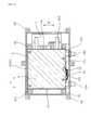
本例の電力変換装置1は、図1に示すごとく、電力変換回路を構成する複数の電子部品(半導体モジュール21、コンデンサ22等)と、少なくとも一部の電子部品(本例においては半導体モジュール21)を冷却する冷却器3とを、ケース4内に収容してなる。
半導体モジュール21と冷却器3とは、これらが固定されるフレーム5と共に一体化されて一つの内部ユニット10を構成している。
内部ユニット10は、ケース4に固定されると共にケース4内に密封されている。Example 1
A power conversion device according to an embodiment of the present invention will be described with reference to FIGS.
As shown in FIG. 1, the
The
The
図16〜図18に示すごとく、内部ユニット10は、フレーム5においてケース4に固定されている。フレーム5は、導体からなり、内部ユニット10を構成する複数の半導体モジュール21を四方から囲むように形成されている。フレーム5は、例えば、アルミニウム、鉄等の金属又は合金の成形体によって構成することができる。
また、ケース4も、例えば、アルミニウム、鉄等の金属又は合金からなる。As shown in FIGS. 16 to 18, the
The
半導体モジュール21は、例えばIGBT(絶縁ゲートバイポーラトランジスタ)、MOSFET(MOS型電界効果トランジスタ)等のスイッチング素子を内蔵してなる。半導体モジュール21は、スイッチング素子を樹脂モールドしてなる本体部211と、該本体部211から互いに反対方向に突出した主電極端子212及び制御端子213とからなる。主電極端子212からは被制御電力が半導体モジュール21に入出力され、制御端子213には、スイッチング素子を制御する制御電流が入力される。 The
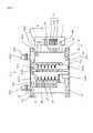
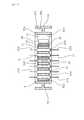
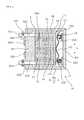
図7、図10に示すごとく、冷却器3は内部に冷媒流路を備える複数の冷却管31を有する。そして、複数の冷却管31と複数の半導体モジュール21とが互いに積層された積層体11が内部ユニット10に含まれている。積層体11は、冷却管31と半導体モジュール21とを交互に積層してなる。そして、半導体モジュール21は両主面から冷却管31によって挟持されている。また、隣り合う冷却管31の間には、2個の半導体モジュール21が挟持されている。 As shown in FIGS. 7 and 10, the
図7に示すごとく、複数の冷却管31は、積層方向Xに直交する方向に長く、その長手方向(この方向を、以下、適宜「横方向Y」という。)の両端部において、隣り合う冷却管31同士が変形可能な連結管32によって連結されている。冷却器3は、積層方向Xの一端に配された冷却管31における横方向Yの両端部に設けた冷媒導入管331及び冷媒排出管332を有する。 As shown in FIG. 7, the plurality of cooling
これにより、冷媒導入管331から導入された冷却媒体は、連結管32を適宜通り、各冷却管31に分配されると共にその長手方向(横方向Y)に流通する。そして、各冷却管31を流れる間に、冷却媒体は半導体モジュール21との間で熱交換を行う。熱交換により温度上昇した冷却媒体は、下流側の連結管32を適宜通り、冷媒排出管332に導かれ、冷却器3から排出される。 Thereby, the cooling medium introduced from the
冷却媒体としては、例えば、水やアンモニア等の自然冷媒、エチレングリコール系の不凍液を混入した水、フロリナート等のフッ化炭素系冷媒、HCFC123、HFC134a等のフロン系冷媒、メタノール、アルコール等のアルコール系冷媒、アセトン等のケトン系冷媒等の冷媒を用いることができる。 Examples of the cooling medium include natural refrigerants such as water and ammonia, water mixed with ethylene glycol-based antifreeze, fluorocarbon refrigerants such as fluorinate, chlorofluorocarbon refrigerants such as HCFC123 and HFC134a, and alcohol-based alcohols such as methanol and alcohol. A refrigerant such as a refrigerant or a ketone-based refrigerant such as acetone can be used.
内部ユニット10は、積層体11を積層方向Xに加圧する加圧部材12を備える。加圧部材12は、フレーム5の一部と積層体11における積層方向Xの一端(これを以下「後端」という。)との間に介設されている。積層体11における積層方向Xの他端(これを以下「前端」という。)は、フレーム5の他の一部によって支承されている。 The
加圧部材12は、積層体11側に向って凸状に湾曲した板ばねによって構成されている。また、加圧部材12と積層体11との間には、平板状の補強板13が介設されており、加圧部材12の押圧力が冷却管31に局部的にかからないようにして、冷却管31の変形を防いでいる。また、加圧部材12の長手方向(横方向Y)の両端部と、フレーム5との間には、支承ピン14が挟持されている。この一対の支承ピン14によって、加圧部材12が後方から支承されている。 The pressing
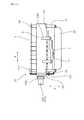
フレーム5は、積層体11における積層方向Xの両側に配された前方壁部52及び後方壁部53と、前方壁部52と後方壁部53とをその両端において連結する一対の側方壁部54とを有する。すなわち、図2、図3に示すごとく、フレーム5は、積層方向X及び横方向Yに直交する方向(以下、これを「高さ方向Z」という。)から見たとき、略長方形状を有する。 The
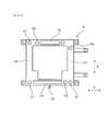
フレーム5は、図1〜図3、図19に示すごとく、内部ユニット10をケース4に固定するユニット固定部51を複数有している。積層体11及び加圧部材12による積層方向Xの外側へ向かう反力を受けるフレーム5における一対の支承部(前方壁部52の内側面521および後方壁部53の内側面531)よりも積層方向Xの外側の双方に、少なくとも1個ずつユニット固定部51が配置されている。本例においては、上記内側面521よりも外側に2個のユニット固定部51が形成され、上記内側面531よりも外側に他の2個のユニット固定部51が形成されている。 As shown in FIGS. 1 to 3 and 19, the
ユニット固定部51は、フレーム5から外方へ突出形成されると共に貫通孔が形成されている。該貫通孔にボルト511を挿通すると共に該ボルト511をケース4の内部に形成されたユニット支承部41におけるネジ孔に螺合することにより、フレーム5をケース4に固定し、すなわち、内部ユニット10をケース4に固定している。 The
図2、図4、図5に示すごとく、前方壁部52及び後方壁部53は、側方壁部54よりも、壁厚みt1、t2が大きい。ここで、壁厚みt1、t2とは、冷却管31が、積層方向Xあるいは横方向Yに投影される部分における、積層方向Xあるいは横方向Yの寸法をいうものとする。 As shown in FIGS. 2, 4, and 5, the
前方壁部52及び後方壁部53は、その少なくとも一部を、図4、図10に示すごとく、断面略H字形状のH型壁部55によって構成してある。H型壁部55は、積層方向Xに垂直な一対の縦板部551と該一対の縦板部551の中央部においてこれらを連結する連結部552とからなる。 As shown in FIGS. 4 and 10, at least a part of the
図2、図3に示すごとく、側方壁部54は、その一部を、断面略L字状のL型壁部によって構成してある。L型壁部(側方壁部54)は、図5に示すごとく、フレーム5の内側に面する主面を有する主壁部541と、該主壁部541における積層方向Xに直交する方向の一端からフレーム5の内側に向って突出した内向部542とからなる。本例においては、側方壁部54のすべてが上記L型壁部からなる。
なお、図2、図7に示すごとく、支承ピン14を配置する領域付近においては、側方壁部54の内向部542が他の部分よりも内側に突出している。As shown in FIGS. 2 and 3, a part of the
As shown in FIGS. 2 and 7, in the vicinity of the region where the
フレーム5は、高さ方向Zの双方に解放されている。すなわち、フレーム5の内側は高さ方向Zに貫通してなる。そして、図9、図10に示すごとく、半導体モジュール21の主電極端子212及び制御端子213は、フレーム5における高さ方向Zの一方(下方)と他方(上方)に突出している。本明細書において、主電極端子212の突出方向を下方、制御端子213の突出方向を上方として説明するが、上下は特に限定されるものではなく、便宜的なものである。
なお、前後や横などの表現も、同様に便宜的なものであることは言うまでもない。The
Needless to say, expressions such as front and rear and side are also convenient.
また、図1、図13〜図19に示すごとく、内部ユニット10は、スイッチング素子を制御する制御回路を形成した制御回路基板6を備えている。半導体モジュール21における制御端子213は、制御回路基板6に接続されている。図13、図14に示すごとく、フレーム5におけるユニット固定部51は、制御回路基板6の外縁よりも外側に配置されている。 As shown in FIGS. 1 and 13 to 19, the
また、フレーム5は、図2、図14、図15に示すごとく、内部ユニット10に制御回路基板6を固定する基板固定部56を、ユニット固定部51よりも内側に設けている。
基板固定部56は、前方壁部52と後方壁部53とのそれぞれから2本ずつ高さ方向Z(上方)へ突出形成されたボスによって構成されている。これらの基板固定部56にはネジ孔が形成されており、4個所の基板固定部56においてビス561によって制御回路基板6をフレーム5に固定してある(図13〜図15)。Further, as shown in FIGS. 2, 14, and 15, the
The
また、図14、図15に示すごとく、内部ユニット10はコンデンサ22を備えている。フレーム5は、内部ユニット10にコンデンサ22を固定するコンデンサ固定部57を有する。図3、図11、図14に示すごとく、該コンデンサ固定部57は、ユニット固定部51よりも内側に配置されている。
コンデンサ固定部57は、前方壁部52と後方壁部53とのそれぞれから2本ずつ、基板固定部56とは反対側の高さ方向Z(下方)へ突出形成されたボスによって構成されている。これらのコンデンサ固定部57にはネジ孔が形成されており、4個所のコンデンサ固定部57においてボルト571によってコンデンサ22をフレーム5に固定してある。Further, as shown in FIGS. 14 and 15, the
Two
また、図11〜図15に示すごとく、内部ユニット10は、被制御電力を入出力する入出力端子71を載置して、該入出力端子71を外部機器(直流バッテリー、回転電機等)の端子と接続するための端子台7を備えている。
端子台7は、フレーム5における一方の側方壁部54から外方へ突出形成された2本の支持アーム543に、ボルト544によって固定されている。Also, as shown in FIGS. 11 to 15, the
The
入出力端子71には、コンデンサ22の一対の電極と電気的に接続された一対のコンデンサ端子71P、71Nと、半導体モジュール21の主電極端子212と電気的に接続されると共に三相交流回転電機のU相、V相、W相の各電極に接続される3本の出力端子71U、71V、71Wがある。
入出力端子71は、バスバーの一端に形成され、該バスバーの他端がコンデンサ22や半導体モジュール21に接続されている。The input /
The input /
複数本のバスバーのうち、出力端子71U、71V、71Wをそれぞれ有するバスバー70は、互いに樹脂によって部分的にモールドされることによって一体化されたバスバーアッセンブリ72を構成してなる。
フレーム5は、図3、図14、図15に示すごとく、バスバーアッセンブリ72を固定するバスバー固定部58を複数有する。本例においては、バスバー固定部58は3個形成されている。そして、バスバー固定部8のうちの2個は、フレーム5の中央よりも端子台7に近い位置に配置されている。Of the plurality of bus bars, the
As shown in FIGS. 3, 14, and 15, the
内部ユニット10は、電力変換回路を構成するすべての電子部品を含んでいる。すなわち、電力変換装置1におけるすべての電子部品は、内部ユニット10に属しており、ケース4に直接固定された電子部品は存在しない。
また、図1に示すごとく、ケース4は、上方が開口したケース本体40と、該ケース本体40の開口部を閉塞する蓋体400とからなる。上記ユニット支承部41は、ケース本体40と一体成形されている。The
As shown in FIG. 1, the
ケース本体40は、開口部の外周にフランジ部42を設けてなり、蓋体400の外周にもフランジ部420が設けてある。ケース本体40と蓋体400とは、互いの開口端にシール材(図示略)を介在させた状態で両者のフランジ部42、420を互いに重ね合わせ、ボルト431とナット432とによって締結されている。これにより、内部ユニット10は、ケース4内に密封されることとなる。 The case
図16、図19に示すごとく、積層体11(図7参照)に接続された冷媒導入管331及び冷媒排出管332は、その一部をケース4の外に突出させている。冷媒導入管331及び冷媒排出管332の外周には、環状パッキン333が取り付けてある。図16に示すごとく、ケース本体40には、冷媒導入管331及び冷媒排出管332を通過させる凹部44が2個所に形成されており、これら2つの凹部44に、冷媒導入管331及び冷媒排出管332に取り付けた環状パッキン333を配置した状態で、環状パッキン333をケース本体40と蓋体400とで挟持する。これにより、冷媒導入管331及び冷媒排出管332をケース4の外に突出させつつ、ケース4を密閉することができる。 As shown in FIGS. 16 and 19, a part of the
また、内部ユニット10における各種電子部品や制御回路基板6と、外部機器とを電気的に接続するために、ケース4には適宜、配線の挿通部や、コネクタ等を設けてあるが、これらの開口部には、適宜シール材等を設けることによって、ケース4内外の水密性を確保している。 Further, in order to electrically connect various electronic components in the
本例の電力変換装置1を組み立てるに当たっては、まず、図13〜図15に示すごとく、内部ユニット10を組み立てる。その後、図16〜図18に示すごとく、内部ユニット10をケース本体40内に収納すると共に固定する。そして、最後に、図1、図19に示すごとく、蓋体400をケース本体40に締結することによって、ケース4内に内部ユニット10を密封する。 In assembling the
内部ユニット10を組み立てるに当たっては、まず、図2〜図6に示すフレーム5を用意する。
次いで、フレーム5の内側に、図7、図10に示すごとく、複数の半導体モジュール21と複数の冷却管31とを積層してなる積層体11を配置する。なお、この段階より前に、複数の冷却管31は連結管32によって連結されていると共に冷媒導入管331及び冷媒排出管332が接合された冷却器3が既に組み立てられている。積層体11をフレーム5の内側に配置したとき、冷媒導入管331及び冷媒排出管332は、図7に示すごとく、フレーム5に形成した管用凹面522(図2、図6)に載置される。In assembling the
Next, as shown in FIGS. 7 and 10, a
また、積層体11の後端とフレーム5の後方壁部53との間に、加圧部材12を配置する。
次いで、加圧部材12の両端部付近を積層方向Xの前方へ、押圧治具によって押し込むことによって、加圧部材12を弾性変形させつつ、積層体11を圧縮する。加圧部材12を所定量変形させた時点で、加圧部材12の両端部とフレーム5の後方壁部53との間に、円柱状の支承ピン14を挿入する。その後、上記押圧治具を後方へ移動させながら加圧部材12から離すことにより、一対の支承ピン14が加圧部材12と後方壁部53との間に挟持された状態となる。この状態は、すなわち、加圧部材12の付勢力によって積層体11が積層方向に所定の圧力によって圧縮された状態でもある。Further, the
Next, the
次いで、図7〜図9に示すごとく、端子台7をフレーム5における支持アーム543に、ボルト544によって固定する。
次いで、バスバー70を樹脂モールドしてなるバスバーアッセンブリ72をフレーム5に取り付けると共に、バスバー70を半導体モジュール21の主電極端子212に溶接する。また、バスバー70における出力端子71U、71V、71Wを端子台7に載置する。バスバーアッセンブリ72は、フレーム5の3箇所のバスバー固定部58において、ボルト581によって固定する。Next, as shown in FIGS. 7 to 9, the
Next, a
次いで、半導体モジュール21をコンデンサ22と接続するためのバスバー700を、半導体モジュール21の主電極端子212に溶接すると共にバスバーアッセンブリ72にボルト701によって固定する。 Next, the
次いで、図11、図12に示すごとく、コンデンサ22をフレーム5の下側に固定する。すなわち、コンデンサ22をフレーム5におけるコンデンサ固定部57にボルト571によって締結する。
また、コンデンサ22における一対のコンデンサ端子71P、71Nを端子台7に載置する。Next, as shown in FIGS. 11 and 12, the
In addition, a pair of
次いで、図13〜図15に示すごとく、制御回路基板6をフレーム5の上側に配置して、制御回路基板5に形成したスルーホールに半導体モジュール21の制御端子213を挿通すると共に接続する。そして、フレーム5における基板固定部56に、ビス561によって制御回路基板6を固定する。
以上により、内部ユニット10が完成する。Next, as shown in FIGS. 13 to 15, the
Thus, the
その後、図16〜図18に示すごとく、内部ユニット10を、ケース本体40に固定する。
すなわち、ケース本体40に形成されたユニット支承部41の上面に、内部ユニット10の外郭を構成するフレーム5のユニット固定部51を載置する。このとき、冷却器3の冷媒導入管331及び冷媒排出管332に取り付けた環状パッキン333を、ケース本体40に形成された凹部44に嵌め込む。
この状態で、ボルト511を、ユニット固定部51に設けた挿通孔に挿通すると共にユニット支承部41に設けたネジ孔にねじ込むことによって、ケース本体40に内部ユニット10を固定する。Thereafter, as shown in FIGS. 16 to 18, the
That is, the
In this state, the
次いで、シール材を介在させながら、図1、図19に示すごとく、蓋体400をケース本体40の開口部に配置し、フランジ部42、420において、ボルト431とナット432とによって両者を締結する。これにより、内部ユニット10をケース4内に密封する。
以上により、電力変換装置1を完成させる。Next, as shown in FIGS. 1 and 19, with the sealing material interposed, the
Thus, the
次に、本例の作用効果につき説明する。
上記電力変換装置1においては、電子部品(半導体モジュール21、コンデンサ22等)と冷却器3とをフレーム5に固定し、これらの電子部品と冷却器3とフレーム5とを一体化した一つの内部ユニット10を構成している。そして、該内部ユニット10をケース4内に固定している。そのため、内部ユニット10がケース4の内部において梁の役割を果たし、ケース4の剛性を高めることができる。
そして、これによって、ケース4自体の肉厚を特に大きくしたり、補強リブを形成したりしなくても、充分な剛性を得ることができるため、ケース4の材料コストや製造コストを低減することができると共に、その重量を低減することが可能となる。Next, the function and effect of this example will be described.
In the
As a result, sufficient rigidity can be obtained without particularly increasing the thickness of the
また、内部ユニット10をケース4に固定することによって、内部ユニット10に含まれる一つ一つの電子部品及び冷却器3に対して、ケース4を通じて外力が加わることを抑制することができる。すなわち、外部からの振動や、熱応力などの影響を、内部ユニット10に含まれる電子部品及び冷却器3が受けることを抑制することができる。 In addition, by fixing the
また、内部ユニット10を構成することによって、ケース4に直接電子部品をはじめとする各種部品を組み付けるのではなく、フレーム5に対して電子部品等を組み付けて内部ユニット10を組み立てた後、内部ユニット10をケース4に組み付けることで、電力変換装置1を得ることができる。そのため、電力変換装置1の組み立て作業を容易に行うことができる。
また、メンテナンス時においても、内部ユニット10ごとケース4から取り出して、ケース4の外でメンテナンスを行うことができるため、その作業性を向上させることができる。In addition, by configuring the
Further, even during maintenance, the entire
また、このようにケース4の外部において電子部品の組み付けやメンテナンスを行うことができるため、ケース4には複数の蓋を設ける必要がない。そのため、ケース本体40と蓋体400との間のシール面を一箇所とすることができる。それゆえ、ケース4の水密性を高めやすくなると共に、シール材を少なくすることができ、材料費の低減、シール材の塗布等の工数の低減を図ることができる。
また、内部ユニット10はケース4内に密封されている。すなわち、フレーム5を含めて内部ユニット10全体をケース4内に密封してあるため、シール面を一箇所とすることができる。In addition, since electronic components can be assembled and maintained outside the
The
また、内部ユニット10は、フレーム5においてケース4に固定されており、フレーム5が上述した梁の役割を直接果たすため、より一層ケース4の剛性を高めることができる。
また、フレーム5は、導体からなり、複数の半導体モジュール21を四方から囲むように形成されているため、フレーム5によって、半導体モジュール21から生じる電磁ノイズを遮蔽することができる。ケース4も導体によって構成されているが、フレーム5とケース4とによって、半導体モジュール21の電磁ノイズを二重で遮蔽することができる。また、フレーム5は、半導体モジュール21を四方から囲むように形成されているため、電力変換装置1の四方への電磁ノイズの漏れを抑制することができる。In addition, the
Further, since the
また、電力変換装置1においては、電子部品(半導体モジュール21、コンデンサ22等)及び冷却器3をフレーム5に固定してなる内部ユニット10を、フレーム5においてケース4に固定してある。そのため、フレーム5との固定部(ユニット支承部41)さえ統一しておけば、ケース4の外形を、電力変換装置2の被搭載部(エンジンルーム等)に応じて変更することで、ケース4内のレイアウトを車種ごとに変更する必要がない。その結果、内部ユニット10の構造を変更することなく、ケース4の外形のみを変更することで、多種にわたる車種に対応することができる。したがって、生産性に優れた、低コストの電力変換装置1を得ることが可能となる。 In the
しかし、上記電力変換装置1のように、ケース4とフレーム5とを組み合わせた構造の場合、ケース4に対してフレーム5を組み付ける際に発生するフレーム5の寸法公差や組付公差により、ケース4から突出する冷媒導入管331及び冷媒排出管332の位置精度が低下するおそれがある。 However, in the case of the structure in which the
そこで、電力変換装置1においては、前方壁部52の壁厚みを、側方壁部54よりも大きくしている。これにより、フレーム5の大型化、重量化を招くことなく、冷媒導入管331及び冷媒排出管332の位置決め精度を高めて、電力変換装置1の被搭載部への搭載性を効果的に向上させることができる。すなわち、車両のエンジンルームなどの被搭載部へ電力変換装置1を搭載するにあたっては、被搭載部の周囲に設けられた冷媒配管に、冷媒導入管331及び冷媒排出管332をそれぞれ接続する必要がある。したがって、電力変換装置1の搭載性を高めるためには、冷媒導入管331及び冷媒排出管332のケース4に対する位置決めが精度よく行われる必要がある。そこで、冷媒導入管331及び冷媒排出管332を支承する前方壁部52の壁厚みを大きくすることにより、冷媒導入管331及び冷媒排出管332の突出方向が精確に決まり、これらの位置決め精度を高めることが可能となる。このとき、フレーム5のすべての部分の壁厚みを大きくすると、フレーム5の大型化、重量化を招くこととなる。しかし、冷媒導入管331及び冷媒排出管332の位置決めには直接関係のない側方壁部54の壁厚みは比較的小さくてもよい。そこで、側方壁部54よりも前方壁部52の壁厚みを大きくすることにより、フレーム5の大型化、重量化を招くことなく、冷媒導入管331及び冷媒排出管332の位置決め精度を高めて、電力変換装置1の被搭載部への搭載性を効果的に向上させることができる。 Therefore, in the
また、図7、図10に示すごとく、複数の冷却管31と複数の半導体モジュール21とが互いに積層された積層体11が内部ユニット10に含まれている。これにより、積層体11をケース4の外において組み立てることができるため、一層製造容易な電力変換装置1を得ることができる。 As shown in FIGS. 7 and 10, the
また、積層体11は、冷却管31と上記半導体モジュール21とを交互に積層してなるため、半導体モジュール21を効率的に冷却することができると共に、積層体11の小型化を実現することができる。 In addition, since the
また、内部ユニット10は、加圧部材12を備えている。そして、加圧部材12は、フレーム5における後方壁部53と積層体11の後端との間に介設され、積層体11の前端は、フレーム5における前方壁部52によって支承されている。それゆえ、加圧部材12の反力をフレーム5によって支えることができる。そのため、ケース4には加圧部材12の反力に対抗する剛性が必要なく、その厚みを厚くしたり、リブ等を設けたりする必要もない。その結果、ケース4の軽量化、低コスト化を実現することができる。 The
また、フレーム5は、ユニット固定部51を複数有して、積層体11及び加圧部材12による積層方向Xの外側へ向かう反力を受けるフレーム5における一対の支承部(前方壁部52の内側面521及び後方壁部53の内側面531)よりも積層方向Xの外側の双方に、2個ずつユニット固定部51が配置されている。これにより、積層体11及び加圧部材12による反力に対するフレーム5の剛性をケース4によって向上させることができる。すなわち、ケース4がフレーム5を補強することとなり、反力によってフレーム5が変形することを効果的に防止することができる。 The
また、フレーム5は、前方壁部52及び後方壁部53と一対の側方壁部54とを有する。これにより、積層体11をフレーム5の内側において安定して固定することができる。
また、前方壁部52及び後方壁部53は、側方壁部54よりも、壁厚みが大きい。すなわち、図4、図5に示す板厚みt1、t2が、t1>t2である。これにより、加圧部材12の反力を受ける前方壁部52及び後方壁部53の剛性を高めることができると共に、加圧部材12の反力を直接受けない側方壁部54の軽量化を図ることができる。その結果、加圧部材12の反力に対抗するのに必要なフレーム5の剛性を確保しつつ、効果的にフレーム5の軽量化を図ることができる。The
The
また、図4に示すごとく、前方壁部52及び後方壁部53は、その一部を、断面略H字形状のH型壁部55によって構成してある。これにより、前方壁部52及び後方壁部53の高い剛性を確保しつつフレーム5の軽量化を図ることができる。
また、図5に示すごとく、側方壁部54は、断面略L字状のL型壁部によって構成してあるため、充分な剛性を確保しつつ側方壁部54の軽量化及び材料費の低減を図ることができる。Further, as shown in FIG. 4, the
Further, as shown in FIG. 5, since the
また、図10に示すごとく、冷却管31と共に積層された半導体モジュール21は、主電極端子212と制御端子213とを、互いに反対方向へ突出形成してなると共に、高さ方向Zに突出させており、フレーム5は、高さ方向Zの双方に解放されている。これにより、図8、図13〜図15に示すごとく、半導体モジュール21へのバスバー70、700や制御回路基板6の組み付けを容易に行うことができる。 Further, as shown in FIG. 10, the
また、内部ユニット10は、制御回路基板6をも備えている。そのため、制御回路基板6をケース4に直接取り付ける必要がないため、その組み付け作業を容易に行うことができると共に、制御回路基板6へ加わる外力を低減することができる。 The
また、図2に示すごとく、フレーム5に設けたユニット固定部51は、制御回路基板6の外縁よりも外側に配置されている。それゆえ、内部ユニット10をケース4に容易に組み付けることができる。すなわち、仮に、ユニット固定部51が制御回路基板6の外縁よりも内側に配置されていたとすると、制御回路基板6が邪魔になって、制御回路基板6を組み付けた後の内部ユニット10をケース4に固定する作業を容易に行うことができなくなる。 Further, as shown in FIG. 2, the
例えば、ケース4の壁に孔をあけて、そこにボルト等を挿通して内部ユニット10をケース4に固定するなどの方法を採らざるをえなくなるが、その場合、作業性が低下するばかりでなく、ケース4内外の水密性を確保するためのシール材の配設部分が増えてしまうという問題も生じる。
しかし、ユニット固定部51を制御回路基板6の外縁よりも外側に配置しておくことにより、このような不具合を招くおそれがない。For example, a method of drilling a hole in the wall of the
However, by disposing the
また、フレーム5に設けた基板固定部56は、ユニット固定部51よりも内側に配置されている。そのため、制御回路基板6をフレーム5に容易に固定することができると共に、内部ユニット10をケース4に容易に組み付けることができる。 Further, the
また、内部ユニット10はコンデンサ22をも備えている。それゆえ、コンデンサ22へ加わる外力を低減することができる。また、コンデンサ22からケース4へ伝わる振動を抑制することができ、ケース4を介してコンデンサ22の振動が外部へ伝わることを抑制することができる。これにより、例えば、電力変換装置1を搭載した車両において、コンデンサ22の振動に起因する不快音が車内に伝達することを抑制することができる。 The
また、図3に示すごとく、フレーム5に設けたコンデンサ固定部57は、ユニット固定部51よりも内側に配置されている。そのため、コンデンサ22をフレーム5に容易に固定することができると共に、内部ユニット10をケース4に容易に組み付けることができる。 Further, as shown in FIG. 3, the
また、内部ユニット10は、端子台7をも備えている。これにより、ケース4の外で端子台7を内部ユニット10に組み付けることができるため、端子台7の組み付けを容易に行うことができる。 The
また、フレーム5は、バスバー70(バスバーアッセンブリ72)を固定するバスバー固定部58を複数有する。これにより、バスバー70(バスバーアッセンブリ72)をフレーム5に安定して固定することができる。
また、図3、図8に示すごとく、複数のバスバー固定部58のうちの2個は、フレーム5の中央よりも端子台7に近い位置に配置されている。これにより、バスバーアッセンブリ72をフレーム5に安定して固定することができると共に、端子台7に入出力端子71を安定して配置することができる。その結果、入出力端子71と外部端子との安定した接続状態を確保することができる。Further, the
As shown in FIGS. 3 and 8, two of the plurality of bus
また、内部ユニット10は、電力変換回路を構成するすべての電子部品を含んでいる。そのため、電力変換回路を構成するすべての電子部品を外力から保護することができると共に、製造容易かつメンテナンス性に優れた電力変換装置1を得ることができる。 Further, the
以上のごとく、本例によれば、ケースの剛性を高めつつ、電子部品へ加わる外力を低減することができ、かつ、メンテナンス性、搭載性に優れた低コストの電力変換装置を提供することができる。 As described above, according to this example, it is possible to reduce the external force applied to the electronic component while increasing the rigidity of the case, and to provide a low-cost power conversion device excellent in maintainability and mountability. it can.
(実施例2)
本例は、図20〜図26に示すごとく、フレーム5に導電ワイヤー15を保持するワイヤー保持部59を設けた電力変換装置1の例である。
上記導電ワイヤー15は、少なくとも一方の端部がケース4内に配されている。本例においては、導電ワイヤー15は、ケース4内において、コンデンサ22と制御回路基板6との間を接続している。そして、この導電ワイヤー15を通じて、コンデンサ22にかかる電圧、すなわち電力変換装置1への入力電圧の信号を制御回路基板6へ送ることができるようにしてある。
導電ワイヤー15は、両端部を除いて樹脂によって被覆された被覆導線からなり、可撓性を有する。そして、導電ワイヤー15は、フレーム5の外側を通過して、制御回路基板6とコンデンサ22とを接続している。(Example 2)
This example is an example of the
At least one end of the
The
ワイヤー保持部59は、図21、図23、図25、図26に示すごとく、上記高さ方向Zから見た形状が鉤状を有し、図20、図22、図24に示すごとく、高さ方向Zに長く形成されている。ワイヤー保持部59は、フレーム5における前方壁部52から外側へ突出形成されている。そして、図21、図23に示すごとく、ワイヤー保持部59と前方壁部52との間の空間に、導電ワイヤー15の一部を嵌合させている。 As shown in FIGS. 21, 23, 25, and 26, the
また、図20〜図23に示すごとく、バスバーアッセンブリ72には、積層方向Xの前方へ突出した前方突出部721が形成されており、該前方突出部721は、高さ方向Zから見たとき、ワイヤー保持部59の開口側に対向する位置に配されている。そして、この前方突出部721によって、導電ワイヤー15がワイヤー保持部59から外れないようにしてある。
また、ワイヤー保持部59は、導電ワイヤー15における制御回路基板6との接続部151と、略同等の横方向Yの位置に配置されている。
その他は、実施例1と同様である。Further, as shown in FIGS. 20 to 23, the
Further, the
Others are the same as in the first embodiment.
本例の場合には、導電ワイヤー15をフレーム5に沿わせることができる。それゆえ、内部ユニット10をケース4に収納したり、あるいはケース4から取り出したりする際に、導電ワイヤー15が引っかかるなどの不具合を防止することができる。
その他、実施例1と同様の作用効果を有する。In the case of this example, the
In addition, the same effects as those of the first embodiment are obtained.
なお、ワイヤー保持部59に保持させる導電ワイヤー15は、上記のように、コンデンサ22と制御回路基板6との間に接続されるものに限らず、他の導電ワイヤーであってもよい。また、ワイヤー保持部59の形成方向や形成位置、或いは形状等についても、限定されるものではなく、例えば、横方向Yに導電ワイヤー15を添わせるように形成することもできる。また、必要に応じて、ワイヤー保持部59をフレーム5の複数個所に設けることもできる。 Note that the
(実施例3)
本例は、図27〜図33に示すごとく、半導体モジュール21と共に他の電子部品20をもフレーム5の内側に配置した例である。
上記他の電子部品20は、半導体モジュール21以外の電子部品であり、例えば、リアクトルやコンデンサとすることができる。(Example 3)
In this example, as shown in FIGS. 27 to 33, other
The other
また、図27、図28に示すごとく、冷却器3もフレーム5の内側に配設されている。本例の電力変換装置1は、半導体モジュール21を、冷却器3によって片面から冷却する構造としている。そして、冷却器3を構成する冷却管31の一方の面がフレーム5の前方壁部52の内側面521に当接し、冷却管31における他方の面に3個の半導体モジュール21が当接している。また、半導体モジュール21とフレーム5の後方壁部53との間に、電子部品20が配設されている。 As shown in FIGS. 27 and 28, the
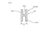
冷却器3は、冷媒導入管331と冷媒排出管332とを、前方壁部52に支承させつつ前方壁部52からフレーム5の外方へ突出するように形成している。そして、前方壁部52は、側方壁部54よりも壁厚みが大きい。
また、図29に示すごとく、前方壁部52は、冷媒導入管331及び冷媒排出管332をそれぞれ配置するための一対の管用凹部522を設けてなる。管用凹部522は、図30に示すごとく、開口側へ向かって幅が広がるようなV字溝形状としてもよいし、図31に示すごとく、互いに略平行な側面を有するU字溝形状としてもよい。The
Further, as shown in FIG. 29, the
前方壁部52は、一対の管用凹部522の間の中央部分523において冷却器3の前面34と接触している。一対の管用凹部522の並び方向と冷媒導入管331及び冷媒排出管332の突出方向とに直交する方向である高さ方向Zにおいて、図28、図29に示すごとく、冷却器3の前面34の形成領域h1は、中央部分523の形成領域h2の範囲内に納まっている。 The
冷媒導入管331及び冷媒排出管332は、クランプ部材16によって前方壁部52に対して拘束されている。前方壁部52は、一対の管用凹部522に対して側方壁部54側に隣接する位置に、中央部分523よりも管用凹部522の開口側の端面(上面)が後退した側方隣接部524を有する。すなわち、側方隣接部524は、中央部分523よりも高さ方向Zの高さが低い。 The
前方壁部52は、図32、図33に示すごとく、クランプ部材16を固定する固定ネジ161を螺合させるネジ穴525と、クランプ部材16の回り止め用係合部162を係合させる被係合部526とを備えている。ネジ穴525は、側方隣接部524の上面に形成され、被係合部526は管用凹部522と中央部分523との間に設けられた段部527の上面に穿設されている。
その他は、実施例1と同様である。As shown in FIGS. 32 and 33, the
Others are the same as in the first embodiment.
本例において、前方壁部52は、側方壁部54よりも壁厚みが大きい。これにより、フレーム5の大型化、重量化を招くことなく、冷媒導入管331及び冷媒排出管332の位置決め精度を高めて、電力変換装置1の被搭載部への搭載性を効果的に向上させることができる。すなわち、車両のエンジンルームなどの被搭載部へ電力変換装置1を搭載するにあたっては、被搭載部の周囲に設けられた冷媒配管に、冷媒導入管331及び冷媒排出管332をそれぞれ接続する必要がある。したがって、電力変換装置1の搭載性を高めるためには、冷媒導入管331及び冷媒排出管332のケース4に対する位置決めが精度よく行われる必要がある。そこで、冷媒導入管331及び冷媒排出管332を支承する前方壁部52の壁厚みを大きくすることにより、冷媒導入管331及び冷媒排出管332の突出方向が精確に決まり、これらの位置決め精度を高めることが可能となる。このとき、フレーム5のすべての部分の壁厚みを大きくすると、フレーム5の大型化、重量化を招くこととなる。しかし、冷媒導入管331及び冷媒排出管332の位置決めには直接関係のない側方壁部54の壁厚みは比較的小さくてもよい。そこで、側方壁部54よりも前方壁部52の壁厚みを大きくすることにより、フレーム5の大型化、重量化を招くことなく、冷媒導入管331及び冷媒排出管332の位置決め精度を高めて、電力変換装置1の被搭載部への搭載性を効果的に向上させることができる。 In this example, the
また、前方壁部52は一対の管用凹部522を設けてなるため、冷媒導入管331及び冷媒排出管332の位置決め精度を一層向上させることができる。
また、前方壁部52は、一対の管用凹部522の間の中央部分523において冷却器3の前面34と接触しており、高さ方向Zにおいて、冷却器3の前面34の形成領域h1は、中央部分523の形成領域h2の範囲内に納まっている(図28、図29)。それゆえ、冷却器3の前面34が、前方壁部52の中央部分523から高さ方向Zにはみ出ることなく、前方壁部52に接触することができる。これにより、冷却器3の変形を防ぎ、冷却器3による半導体モジュール21の冷却効率を確保することができる。すなわち、仮に冷却器3の前面34が前方壁部52の中央部分523から高さ方向にはみ出ると、前方壁部52における高さ方向Zの端部において冷却器3が変形するおそれがある。そこで、冷却器3の前面34の形成領域h1を、中央部分523の形成領域h2の範囲内に納めることによって、冷却器3の変形を防ぎ、半導体モジュール21の冷却効率が低下することを防ぐことができる。Further, since the
Further, the
また、冷媒導入管331及び冷媒排出管332は、クランプ部材16によって前方壁部52に対して拘束されており、前方壁部52は、一対の管用凹部522に対して側方壁部54側に隣接する位置に、中央部分523よりも管用凹部522の開口側の端面(上面)が後退した側方隣接部524を有する。それゆえ、側方隣接部524にクランプ部材16を固定することにより、前方壁部52からのクランプ部材16の高さ方向Zへの突出量を抑制することができる。その結果、クランプ部材16の電力変換装置1における他の部品(例えば制御回路基板)との干渉を防ぎ、電力変換装置1の小型化を容易にすることができる。 Further, the
また、前方壁部52は、クランプ部材16を固定する固定ネジ161を螺合させるネジ穴525と、クランプ部材16の回り止め用係合部162を係合させる被係合部526とを備えている。それゆえ、冷媒導入管331及び冷媒排出管332を安定して前方壁部52に締結することができる。これにより、内部ユニット10をケース4内に装着する際、冷媒排出管331及び冷媒排出管332がフレーム5から浮いて位置ずれを招くといった不具合を防止することができる。
その他、実施例1と同様の作用効果を有する。In addition, the
In addition, the same effects as those of the first embodiment are obtained.
(実施例4)
本例は、図34、図35に示すごとく、内部ユニット10が、複数の冷却管31と複数の半導体モジュール21とを交互に積層してなる積層体11を、フレーム5の内側に設けてなる例である。
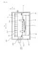
図34に示すごとく、内部ユニット10は、積層体11を積層方向Xに加圧する加圧部材12を備えている。加圧部材12は、フレーム5の後方壁部53と積層体11における積層方向Xの後端との間に介設されている。積層体11における積層方向Xの前端は、前方壁部52によって支承されている。Example 4
In this example, as shown in FIGS. 34 and 35, the
As shown in FIG. 34, the
図35に示すごとく、後方壁部53は、加圧部材12が当接する平面状の後方当接面532を備えている。前方壁部52は、積層体11における積層方向Xの前端が当接する平面状の前方当接面528を備えている。そして、後方当接面532と前方当接面528とは、互いに平行である。すなわち、後方当接面532及び前方当接面528は、それぞれ研削加工或いは研磨加工等によって、他の面よりも平面度の高い表面を構成しており、他の面同士よりも互いの平行度が高く保たれている。 As shown in FIG. 35, the
前方当接面528は、その周囲における前方壁部52の内側面よりも積層体11側へ突出している。後方当接面532も、その周囲における後方壁部53の内側面よりも積層体11側へ突出している。
また、前方壁部52は、その外側面に、前方当接面528と平行な前方外側面529を備えている。前方外側面529についても、後方当接面532及び前方当接面528と同様に、研削加工或いは研磨加工等によって、他の面よりも平面度の高い表面を構成しており、後方当接面532及び前方当接面528に対する平行度が高く保たれている。The
The
前方外側面529は、横方向Yに並んで、2か所に形成されており、2か所の前方外側面529は、互いに同一平面上に形成されている。また、後方当接面532も、横方向Yに並んで、2か所に形成されており、2か所の前方当接部524は、互いに同一平面上に形成されている。 The front
冷媒導入管331及び冷媒排出管332は、ケース4から突出するよう構成されている(図19、図21参照)。冷媒導入管331及び冷媒排出管332とケース4との間には、両者間をシールする環状パッキン333が配設されている。図34に示すごとく、前方壁部52の外側面は、環状パッキン333と対向する位置に、後方へ後退した後退面520を有する。すなわち、後退面520は、環状パッキン333と対向していない前方外側面529よりも後退している。 The
上記のように構成されたフレーム5に積層体11を組み付けるにあたっては、積層体11の前面すなわち冷却器3の前面34をフレーム5の前方壁部52における前方当接面528に対向させるようにして、フレーム5の内側に積層体11を配置する。次いで、積層体11の後端と後方壁部53との間に加圧部材12を配置する。次いで、加圧部材12の両端縁122を前方へ向かって押圧することにより、冷却器3の前面34を前方当接面528に押し付けて、積層体11を積層方向Xに圧縮しつつ、加圧部材12を弾性変形させる。このとき、フレーム5は、前方壁部52における前方外側面529において、支承治具(図示略)によって支承されている。 In assembling the
次いで、加圧部材12が所定量弾性変形した時点で、加圧部材12の両端部121と後方壁部53との間に、一対の支承ピン14を介在させる。この一対の支承ピン14は、後方壁部53における後方当接面532に、それぞれ当接させる。次いで、加圧部材12の復元力を積層体11の後端と後方壁部53との間に作用させることにより、図34に示すごとく、積層体11が積層方向Xに加圧された状態で、フレーム5に組み付けられることとなる。
その他は、実施例3と同様である。Next, when the
Others are the same as in the third embodiment.
本例においては、加圧部材12の反力をフレーム5によって支えることができる。そのため、ケース4には加圧部材12の反力に対抗する剛性が必要なく、その厚みを厚くしたり、リブ等を設けたりする必要もない。その結果、ケース4の軽量化、低コスト化を実現することができる。 In this example, the reaction force of the
また、後方壁部53は後方当接面532を備え、前方壁部52は前方当接面528を備え、後方当接面532と前方当接面528とは互いに平行である。それゆえ、積層体11を積層方向Xにまっすぐに押圧することができるため、半導体モジュール21と冷却管31とが高い平行度にて面接触した状態で圧接することとなる。これにより、半導体モジュール21の冷却効率を向上させることができる。 The
また、前方当接面528は、その周囲における前方壁部52の内側面よりも積層体11側へ突出している。そのため、積層体11と前方壁部52とを当接させる部分以外において、フレーム5と積層体11とが干渉することを防ぐことができる。
また、前方壁部52は、その外側面に前方外側面529を備えている。それゆえ、フレーム5内の積層体11を前方壁部52側へ押圧しながら加圧部材12を組み込む際、押圧方向と反対側からフレーム5を支承する面として、前方外側面529を利用することができる。そして、この前方外側面529は、前方当接面528と平行であるため、押圧力をまっすぐ受けることができる。Further, the
Further, the
また、前方壁部52の外側面は、環状パッキン333と対向する位置に後退面520を有する。それゆえ、環状パッキン333の耐久性を高めると共に、環状パッキン333を所望の位置に正確に配置することが容易となる。すなわち、電力変換装置1の小型化の観点から、積層方向Xにおいて、ケース4とフレーム5との間は極力狭めることが好ましい。この場合、環状パッキン33を冷媒導入管331及び冷媒排出管332に装着する際、環状パッキン333はフレーム5に近接する位置まで押し込むこととなる。ところが、環状パッキン333がフレーム5に押し当ると、フレーム5との干渉によって環状パッキンが摩耗しやすくなる。また、環状パッキン333がフレーム5に押し当てられると、環状パッキン333の弾性力によってその位置がずれるおそれがある。そこで、前方壁部52の外側面に後退面520を設けることにより、上記のような不具合を防ぐことができる。
その他、実施例3と同様の作用効果を有する。Further, the outer surface of the
In addition, the same effects as those of the third embodiment are obtained.
(実施例5)
本例は、図36〜図38に示すごとく、前方壁部52の一部分を断面略H字形状のH型壁部55によって構成し、該H型壁部55にリブ部553をさらに設けた例である。
すなわち、前方壁部52は、図37に示すごとく、積層方向Xに垂直な一対の縦板部551と該一対の縦板部551の中央部においてこれらを連結する連結部552とからなり、さらに、縦板部551及び連結部552に直交するリブ部553を、一対の縦板部551と連結部552との間に部分的に設けてなる。(Example 5)
In this example, as shown in FIGS. 36 to 38, a part of the
That is, as shown in FIG. 37, the
また、後方壁部53も、その一部分を断面略H字形状のH型壁部55によって構成し、該H型壁部55にリブ部553をさらに設けてなる。後方壁部53におけるH型壁部55は、後方壁部53の長手方向(横方向Y)の中央の一箇所にリブ部553を設けてなる。
また、前方壁部52におけるH型壁部55は前方壁部52の長手方向(横方向Y)の二箇所にリブ部553を設けてなる。Further, a part of the
Further, the H-shaped
フレーム5は、実施例1と同様に、高さ方向Zの双方に、電力変換回路を構成する電子部品(制御回路基板6、コンデンサ22、バスバーアッセンブリ72)を固定する部品固定部560(基板固定部56、コンデンサ固定部57、バスバー固定部58)をそれぞれ設けてなる(図2、図3、図14、図15参照)。そして、前方壁部52及び後方壁部53における高さ方向Zの両側に、それぞれ少なくとも一つの部品固定部560が配置されている。 As in the first embodiment, the
本例においても、実施例4と同様に、フレーム5には、後方当接面532、前方当接面528、前方外側面529が形成されている。ただし、本例においては、前方外側面529は1個である。
その他は、実施例4と同様である。なお、図36、図38においては、クランプ部材を省略してある。Also in this example, as in the fourth embodiment, the
Others are the same as in the fourth embodiment. 36 and 38, the clamp member is omitted.
本例において、前方壁部52は、その少なくとも一部分をH型壁部55によって構成してあり、H型壁部55はリブ部553を部分的に設けてなる。それゆえ、前方壁部52の高い剛性を確保しつつフレーム5の軽量化を図ることができる。
また、フレーム5は、高さ方向Zの双方に、部品固定部560をそれぞれ設けてなり、前方壁部53における高さ方向Zの両側に、それぞれ少なくとも一つの部品固定部560が配置されている。それゆえ、フレーム5の積層方向X或いは横方向Yにはみ出すことなく、より多くの電子部品を内部ユニット10に搭載することができる。また、部品固定部560は、壁厚みの厚い前方壁部52における高さ方向Zの両側に配設してあるため、部品固定部560を設けることによってフレーム5が大型化することを抑制することができる。In this example, at least a part of the
Further, the
また、後方壁部53における高さ方向Zの両側にも、それぞれ少なくとも一つの部品固定部560が設けてある。それゆえ、前方壁部52に設けた部品固定部560と、後方壁部53に設けた部品固定部560とにわたって、電子部品をフレーム5に固定することによって、積層方向Xの負荷に対するフレーム5の剛性を高め、その変形を防ぐことができる。例えば、図38に示すごとく、前方壁部52に設けた基板固定部56と後方壁部53に設けた基板固定部56とにわたって、制御回路基板6をフレーム5に固定することによって、積層方向Xのフレーム5の剛性を高めることができる。さらに、前方壁部52及び後方壁部53に設けたコンデンサ固定部57にコンデンサ22を固定することによって、また、前方壁部52及び後方壁部53に設けたバスバー固定部57にバスバーアッセンブリ72を固定することによって、積層方向Xのフレーム5の剛性をさらに高めることができる。
その他、実施例4と同様の作用効果を有する。Also, at least one
In addition, the same effects as those of the fourth embodiment are obtained.
(実施例6)
本例は、図39に示すごとく、フレーム5を、前方壁部52と一対の側方壁部54とによって構成し、内部ユニット10を構成する電子部品(半導体モジュール21及び他の電子部品20)を三方から囲むように形成した例である。
すなわち、本例のフレーム5は、実施例3において示した電力変換装置1(図27)におけるフレーム5のうちの後方壁部53を有していない。それゆえ、高さ方向Zから見たフレーム5の形状は、略コ字状となっている。
その他は、実施例3と同様である。
本例によれば、フレーム5の軽量化、小型化を図ることができる。
その他、実施例4と同様の作用効果を有する。(Example 6)
In this example, as shown in FIG. 39, the
That is, the
Others are the same as in the third embodiment.
According to this example, the
In addition, the same effects as those of the fourth embodiment are obtained.
(実施例7)
本例は、図40に示すごとく、冷媒導入管331と冷媒排出管332とを互いに反対方向に突出させた例である。
すなわち、複数の冷却管31を積層してなる冷却器3は、その前端から冷媒導入管331を前方へ突出形成し、後端から冷媒排出管332を後方へ突出させている。そして、冷媒導入管331を前方壁部52に支承させつつ前方壁部52からフレーム5の外方へ突出させ、冷媒排出管332を後方壁部53に支承させつつ後方壁部53からフレーム5の外方へ突出させている。
前方壁部52及び後方壁部53は、側方壁部54よりも壁厚みが大きい。
その他は、実施例1と同様である。(Example 7)
In this example, as shown in FIG. 40, the
That is, the
The
Others are the same as in the first embodiment.
本例によれば、冷媒導入管331と冷媒排出管332との突出方向が反対側の場合にも、冷媒導入管331及び冷媒排出管332の位置精度を確保することができる。
その他、実施例1と同様の作用効果を有する。
なお、本例とは逆に、冷媒導入管331を後方に突出させて後方壁部53に支承させ、冷媒排出管332を前方から突出させて前方壁部52に支承させてもよい。この場合にも、同様の作用効果を得ることができる。According to this example, the positional accuracy of the
In addition, the same effects as those of the first embodiment are obtained.
In contrast to this example, the
1 電力変換装置
10 内部ユニット
11 積層体
21 半導体モジュール
22 コンデンサ
3 冷却器
31 冷却管
4 ケース
5 フレーム
6 制御回路基板
7 端子台DESCRIPTION OF
Claims (15)
Translated fromJapanese上記電子部品の少なくとも一部と上記冷却器とは、これらが固定されるフレームと共に一体化されて一つの内部ユニットを構成し、
該内部ユニットは、上記フレームにおいて上記ケース内に固定され、
上記フレームは、上記内部ユニットを構成する上記電子部品の少なくとも一部を囲むように形成され、少なくとも前方壁部と、該前方壁部の両端から後方へ延設された一対の側方壁部とを有し、
上記冷却器は、該冷却器内に冷却媒体を導入する冷媒導入管と、上記冷却器から上記冷却媒体を排出する冷媒排出管とを、上記前方壁部に支承させつつ該前方壁部から上記フレームの外方へ突出するように形成してなり、
上記前方壁部は、上記側方壁部よりも壁厚みが大きいことを特徴とする電力変換装置。A power conversion device in which a plurality of electronic components constituting a power conversion circuit and a cooler that cools at least some of the electronic components are housed in a case,
At least a part of the electronic component and the cooler are integrated with a frame to which they are fixed to constitute one internal unit,
The internal unit is fixed in the case in the frame,
The frame is formed so as to surround at least a part of the electronic component constituting the internal unit, and includes at least a front wall portion and a pair of side wall portions extending rearward from both ends of the front wall portion. Have
The cooler supports the refrigerant introduction pipe for introducing the cooling medium into the cooler and the refrigerant discharge pipe for discharging the cooling medium from the cooler from the front wall portion while supporting the front wall portion. It is formed to protrude outward from the frame,
The said front wall part has wall thickness larger than the said side wall part, The power converter device characterized by the above-mentioned.
上記電子部品の少なくとも一部と上記冷却器とは、これらが固定されるフレームと共に一体化されて一つの内部ユニットを構成し、
該内部ユニットは、上記フレームにおいて上記ケース内に固定され、
上記フレームは、上記内部ユニットを構成する上記電子部品の少なくとも一部を四方から囲むように形成され、少なくとも前方壁部及び後方壁部と、上記前方壁部と上記後方壁部とを、その両端において連結する一対の側方壁部とを有し、
上記冷却器は、該冷却器内に冷却媒体を導入する冷媒導入管と、上記冷却器から上記冷却媒体を排出する冷媒排出管とを、両者共に上記前方壁部支承させつつ該前方壁部から、或いは両者の一方と他方とをそれぞれ上記前方壁部と上記後方壁部とに支承させつつ上記前方壁部と上記後方壁部とから、上記フレームの外方へ突出するように形成してなり、
上記前方壁部及び上記後方壁部のうち、上記冷媒導入管及び上記冷媒排出管の少なくとも一方を支承する壁部は、上記側方壁部よりも壁厚みが大きいことを特徴とする電力変換装置。A power conversion device in which a plurality of electronic components constituting a power conversion circuit and a cooler that cools at least some of the electronic components are housed in a case,
At least a part of the electronic component and the cooler are integrated with a frame to which they are fixed to constitute one internal unit,
The internal unit is fixed in the case in the frame,
The frame is formed so as to surround at least a part of the electronic component constituting the internal unit from four directions, and includes at least a front wall portion and a rear wall portion, the front wall portion and the rear wall portion at both ends thereof. A pair of side wall portions connected at
The cooler includes a refrigerant introduction pipe for introducing a cooling medium into the cooler and a refrigerant discharge pipe for discharging the cooling medium from the cooler, both supported from the front wall while supporting the front wall. Alternatively, it is formed so as to protrude outward from the front wall portion and the rear wall portion while supporting one and the other of the both on the front wall portion and the rear wall portion, respectively. ,
Of the front wall portion and the rear wall portion, a wall portion that supports at least one of the refrigerant introduction tube and the refrigerant discharge tube has a wall thickness larger than that of the side wall portion. .
Priority Applications (3)
| Application Number | Priority Date | Filing Date | Title |
|---|---|---|---|
| JP2010244596AJP4924750B2 (en) | 2010-02-05 | 2010-10-29 | Power converter |
| US13/021,926US8582291B2 (en) | 2010-02-05 | 2011-02-07 | Power conversion apparatus |
| CN201110036343.XACN102148562B (en) | 2010-02-05 | 2011-02-09 | Power conversion apparatus |
Applications Claiming Priority (3)
| Application Number | Priority Date | Filing Date | Title |
|---|---|---|---|
| JP2010024557 | 2010-02-05 | ||
| JP2010024557 | 2010-02-05 | ||
| JP2010244596AJP4924750B2 (en) | 2010-02-05 | 2010-10-29 | Power converter |
Publications (2)
| Publication Number | Publication Date |
|---|---|
| JP2011182630A JP2011182630A (en) | 2011-09-15 |
| JP4924750B2true JP4924750B2 (en) | 2012-04-25 |
Family
ID=44353560
Family Applications (1)
| Application Number | Title | Priority Date | Filing Date |
|---|---|---|---|
| JP2010244596AActiveJP4924750B2 (en) | 2010-02-05 | 2010-10-29 | Power converter |
Country Status (3)
| Country | Link |
|---|---|
| US (1) | US8582291B2 (en) |
| JP (1) | JP4924750B2 (en) |
| CN (1) | CN102148562B (en) |
Families Citing this family (47)
| Publication number | Priority date | Publication date | Assignee | Title |
|---|---|---|---|---|
| JP4848187B2 (en)* | 2006-01-17 | 2011-12-28 | 日立オートモティブシステムズ株式会社 | Power converter |
| JP5423655B2 (en)* | 2010-02-05 | 2014-02-19 | 株式会社デンソー | Power converter |
| JP5158176B2 (en)* | 2010-02-05 | 2013-03-06 | 株式会社デンソー | Power converter |
| JP5327195B2 (en)* | 2010-02-05 | 2013-10-30 | 株式会社デンソー | Power converter |
| JP5423654B2 (en) | 2010-02-05 | 2014-02-19 | 株式会社デンソー | Power converter |
| JP5338932B2 (en)* | 2011-07-26 | 2013-11-13 | 株式会社デンソー | Power converter |
| US9030822B2 (en) | 2011-08-15 | 2015-05-12 | Lear Corporation | Power module cooling system |
| US9076593B2 (en) | 2011-12-29 | 2015-07-07 | Lear Corporation | Heat conductor for use with an inverter in an electric vehicle (EV) or a hybrid-electric vehicle (HEV) |
| US8971041B2 (en)* | 2012-03-29 | 2015-03-03 | Lear Corporation | Coldplate for use with an inverter in an electric vehicle (EV) or a hybrid-electric vehicle (HEV) |
| CN104254738B (en)* | 2012-04-27 | 2017-11-03 | 大金工业株式会社 | Refrigerating plant |
| JP5838908B2 (en)* | 2012-05-16 | 2016-01-06 | 株式会社デンソー | Power converter |
| US8902582B2 (en) | 2012-05-22 | 2014-12-02 | Lear Corporation | Coldplate for use with a transformer in an electric vehicle (EV) or a hybrid-electric vehicle (HEV) |
| US8971038B2 (en) | 2012-05-22 | 2015-03-03 | Lear Corporation | Coldplate for use in an electric vehicle (EV) or a hybrid-electric vehicle (HEV) |
| CN202799522U (en)* | 2012-07-28 | 2013-03-13 | 中山大洋电机制造有限公司 | Motor controller structure |
| JP5958223B2 (en)* | 2012-09-18 | 2016-07-27 | トヨタ自動車株式会社 | Power converter |
| JP2014078599A (en)* | 2012-10-10 | 2014-05-01 | Denso Corp | Power conversion device |
| JP5655846B2 (en)* | 2012-12-04 | 2015-01-21 | 株式会社デンソー | Power converter |
| JP5929768B2 (en)* | 2013-01-15 | 2016-06-08 | トヨタ自動車株式会社 | Power converter |
| JP5725067B2 (en) | 2013-03-25 | 2015-05-27 | 株式会社デンソー | Power converter |
| WO2015029446A1 (en)* | 2013-08-30 | 2015-03-05 | 株式会社デンソー | Stacked cooler |
| JP6412877B2 (en)* | 2013-10-28 | 2018-10-24 | 日本発條株式会社 | Pressing structure and pressing unit |
| SG2013094396A (en)* | 2013-12-19 | 2015-07-30 | Rockwell Automation Asia Pacific Business Ctr Pte Ltd | Slice-io housing with side ventilation |
| US9362040B2 (en) | 2014-05-15 | 2016-06-07 | Lear Corporation | Coldplate with integrated electrical components for cooling thereof |
| US9615490B2 (en) | 2014-05-15 | 2017-04-04 | Lear Corporation | Coldplate with integrated DC link capacitor for cooling thereof |
| JP2016063641A (en)* | 2014-09-18 | 2016-04-25 | 株式会社デンソー | Power converter |
| JP6458444B2 (en)* | 2014-10-21 | 2019-01-30 | 株式会社デンソー | Power converter |
| US9756755B2 (en)* | 2014-10-31 | 2017-09-05 | Denso Corporation | Electric power converter |
| JP6435905B2 (en)* | 2015-02-13 | 2018-12-12 | 株式会社デンソー | Power converter |
| US9864352B2 (en) | 2015-06-01 | 2018-01-09 | Rockwell Automation Asia Pacific Business Ctr. Pte., Ltd. | Slice I/O—field power bus breaker |
| US9801313B2 (en) | 2015-06-26 | 2017-10-24 | Microsoft Technology Licensing, Llc | Underwater container cooling via integrated heat exchanger |
| US9844167B2 (en) | 2015-06-26 | 2017-12-12 | Microsoft Technology Licensing, Llc | Underwater container cooling via external heat exchanger |
| US9954409B2 (en)* | 2015-07-27 | 2018-04-24 | Ford Global Technologies, Llc | Power supply device |
| FR3043879B1 (en)* | 2015-11-13 | 2018-08-24 | Valeo Siemens Eautomotive France Sas | BOXING ASSEMBLY FOR ELECTRICAL EQUIPMENT |
| EP3206468B1 (en)* | 2016-02-15 | 2018-12-26 | Siemens Aktiengesellschaft | Converter with an intermediate d.c. circuit |
| JP6686813B2 (en)* | 2016-09-15 | 2020-04-22 | トヨタ自動車株式会社 | Semiconductor device |
| US11284529B2 (en)* | 2016-12-14 | 2022-03-22 | Lg Innotek Co., Ltd. | Electronic component housing and DC-DC converter comprising same |
| JP6737221B2 (en)* | 2017-04-11 | 2020-08-05 | 株式会社デンソー | Electric power steering control device and electronic unit. |
| JP7106947B2 (en)* | 2018-04-03 | 2022-07-27 | 株式会社デンソー | Position detector |
| JP7052610B2 (en)* | 2018-07-13 | 2022-04-12 | 株式会社デンソー | Power converter |
| JP6915633B2 (en)* | 2018-07-25 | 2021-08-04 | 株式会社デンソー | Power converter |
| CN111835209A (en)* | 2019-04-23 | 2020-10-27 | 台达电子工业股份有限公司 | Mounting assembly and inverter assembly suitable for same |
| CN114365406A (en) | 2020-03-05 | 2022-04-15 | 富士电机株式会社 | Power conversion device |
| EP3955285A1 (en)* | 2020-08-14 | 2022-02-16 | Siemens Aktiengesellschaft | Power module and device for cooling a power module |
| US12317457B2 (en) | 2022-05-17 | 2025-05-27 | Dana Canada Corporation | Systems for a heat exchanger with a biasing bracket and mounting plate |
| FR3137532A1 (en)* | 2022-06-30 | 2024-01-05 | Valeo Siemens Eautomotive France Sas | ELECTRICAL SYSTEM WITH COOLING CIRCUIT OF A POWER MODULE |
| KR20240029354A (en)* | 2022-08-26 | 2024-03-05 | 현대자동차주식회사 | Busbar assembly cooling apparatus and electric power inverter module having the same |
| US12337679B2 (en) | 2023-03-16 | 2025-06-24 | Dana Belgium N.V. | Electric drive unit and method for drive unit operation |
Family Cites Families (38)
| Publication number | Priority date | Publication date | Assignee | Title |
|---|---|---|---|---|
| JPH04225310A (en) | 1990-12-27 | 1992-08-14 | Toomee:Kk | Laser beam switching device |
| US5258888A (en)* | 1991-03-15 | 1993-11-02 | Compaq Computer Corporation | Thermal packaging for natural convection cooled electronics |
| JP2809026B2 (en)* | 1992-09-30 | 1998-10-08 | 三菱電機株式会社 | INVERTER DEVICE AND METHOD OF USING INVERTER DEVICE |
| JPH07194139A (en)* | 1993-12-27 | 1995-07-28 | Hitachi Ltd | Electric vehicle inverter cooling device |
| JPH11346480A (en)* | 1998-06-02 | 1999-12-14 | Hitachi Ltd | Inverter device |
| EP2244289B1 (en)* | 2000-04-19 | 2014-03-26 | Denso Corporation | Coolant cooled type semiconductor device |
| JP4595175B2 (en) | 2000-07-21 | 2010-12-08 | 株式会社デンソー | Indirect cooling circuit device |
| JP3793407B2 (en)* | 2000-09-19 | 2006-07-05 | 株式会社日立製作所 | Power converter |
| US6865080B2 (en)* | 2002-01-16 | 2005-03-08 | Rockwell Automation Technologies, Inc. | Compact fluid cooled power converter supporting multiple circuit boards |
| WO2005020276A2 (en)* | 2003-08-21 | 2005-03-03 | Denso Corporation | Power converter and semiconductor device mounting structure |
| JPWO2005071824A1 (en)* | 2004-01-26 | 2007-08-23 | 株式会社日立製作所 | Semiconductor device |
| JP4325486B2 (en)* | 2004-05-20 | 2009-09-02 | 株式会社デンソー | Power conversion unit |
| US8125781B2 (en)* | 2004-11-11 | 2012-02-28 | Denso Corporation | Semiconductor device |
| JP4225310B2 (en) | 2004-11-11 | 2009-02-18 | 株式会社デンソー | Semiconductor device |
| JP2006174572A (en) | 2004-12-15 | 2006-06-29 | Mitsubishi Electric Corp | Power converter |
| JP2006332597A (en)* | 2005-04-28 | 2006-12-07 | Denso Corp | Semiconductor cooling unit |
| JP2007036214A (en) | 2005-06-21 | 2007-02-08 | Diamond Electric Mfg Co Ltd | Cooling structure and cooling device |
| JP4284625B2 (en)* | 2005-06-22 | 2009-06-24 | 株式会社デンソー | Three-phase inverter device |
| JP4756935B2 (en) | 2005-06-29 | 2011-08-24 | 本田技研工業株式会社 | Inverter unit with capacitor |
| US20070165376A1 (en)* | 2006-01-17 | 2007-07-19 | Norbert Bones | Three phase inverter power stage and assembly |
| JP4921154B2 (en)* | 2006-05-16 | 2012-04-25 | 株式会社デンソー | Reactor and power conversion device incorporating the same |
| JP5028085B2 (en) | 2006-12-27 | 2012-09-19 | アイシン・エィ・ダブリュ株式会社 | Electronic circuit device and manufacturing method thereof |
| US8149579B2 (en)* | 2008-03-28 | 2012-04-03 | Johnson Controls Technology Company | Cooling member |
| JP4764365B2 (en)* | 2007-02-28 | 2011-08-31 | 三菱重工業株式会社 | Inverter-integrated electric compressor |
| JP4719187B2 (en)* | 2007-06-15 | 2011-07-06 | トヨタ自動車株式会社 | Semiconductor device cooling structure |
| JP4452953B2 (en) | 2007-08-09 | 2010-04-21 | 日立オートモティブシステムズ株式会社 | Power converter |
| JP4900202B2 (en)* | 2007-11-20 | 2012-03-21 | 株式会社デンソー | Power converter |
| EP2120263A4 (en)* | 2007-11-30 | 2010-10-13 | Panasonic Corp | HEAT DISSIPATING STRUCTURE BASE PLATE, MODULE USING HEAT DISSIPATING STRUCTURE BASE PLATE, AND METHOD FOR MANUFACTURING HEAT DISSIPATING STRUCTURE BASE PLATE |
| JP5157431B2 (en) | 2007-12-27 | 2013-03-06 | 株式会社デンソー | Power converter |
| JP5326334B2 (en) | 2008-04-16 | 2013-10-30 | 株式会社デンソー | Power control unit |
| JP2009266986A (en) | 2008-04-24 | 2009-11-12 | Denso Corp | Power conversion apparatus and manufacturing method thereof |
| JP5241344B2 (en)* | 2008-06-30 | 2013-07-17 | 日立オートモティブシステムズ株式会社 | Power module and power converter |
| CN101452927B (en)* | 2008-12-31 | 2010-06-02 | 中国电力科学研究院 | A self-cooling thyristor valve |
| US8189324B2 (en)* | 2009-12-07 | 2012-05-29 | American Superconductor Corporation | Power electronic assembly with slotted heatsink |
| JP5158176B2 (en)* | 2010-02-05 | 2013-03-06 | 株式会社デンソー | Power converter |
| JP5423655B2 (en)* | 2010-02-05 | 2014-02-19 | 株式会社デンソー | Power converter |
| JP5327195B2 (en)* | 2010-02-05 | 2013-10-30 | 株式会社デンソー | Power converter |
| JP5423654B2 (en)* | 2010-02-05 | 2014-02-19 | 株式会社デンソー | Power converter |
- 2010
- 2010-10-29JPJP2010244596Apatent/JP4924750B2/enactiveActive
- 2011
- 2011-02-07USUS13/021,926patent/US8582291B2/enactiveActive
- 2011-02-09CNCN201110036343.XApatent/CN102148562B/enactiveActive
Also Published As
| Publication number | Publication date |
|---|---|
| CN102148562B (en) | 2014-03-26 |
| CN102148562A (en) | 2011-08-10 |
| US8582291B2 (en) | 2013-11-12 |
| US20110194247A1 (en) | 2011-08-11 |
| JP2011182630A (en) | 2011-09-15 |
Similar Documents
| Publication | Publication Date | Title |
|---|---|---|
| JP4924750B2 (en) | Power converter | |
| JP5423654B2 (en) | Power converter | |
| JP5158176B2 (en) | Power converter | |
| JP5327195B2 (en) | Power converter | |
| JP5423655B2 (en) | Power converter | |
| JP5991345B2 (en) | Power converter | |
| CN102332831B (en) | Power semiconductor device and power conversion device | |
| JP5699995B2 (en) | Power converter | |
| JP6825542B2 (en) | Power converter | |
| JP5314933B2 (en) | Power converter | |
| JP5521978B2 (en) | Power converter | |
| CN107408554B (en) | Power inverter | |
| CN104584408A (en) | power conversion device | |
| US10512199B2 (en) | Power conversion apparatus provided with semiconductor module and electronic component pressurized by pressurizing member | |
| JP6127937B2 (en) | Power converter | |
| JP7107192B2 (en) | power converter | |
| JP2016059167A (en) | Power converter and method for manufacturing power converter | |
| JP5640826B2 (en) | Power converter | |
| JP7056533B2 (en) | Power converter | |
| WO2024157464A1 (en) | Semiconductor device and power conversion device | |
| JP2024020757A (en) | power converter |
Legal Events
| Date | Code | Title | Description |
|---|---|---|---|
| A977 | Report on retrieval | Free format text:JAPANESE INTERMEDIATE CODE: A971007 Effective date:20111214 | |
| TRDD | Decision of grant or rejection written | ||
| A01 | Written decision to grant a patent or to grant a registration (utility model) | Free format text:JAPANESE INTERMEDIATE CODE: A01 Effective date:20120110 | |
| A01 | Written decision to grant a patent or to grant a registration (utility model) | Free format text:JAPANESE INTERMEDIATE CODE: A01 | |
| A61 | First payment of annual fees (during grant procedure) | Free format text:JAPANESE INTERMEDIATE CODE: A61 Effective date:20120123 | |
| FPAY | Renewal fee payment (event date is renewal date of database) | Free format text:PAYMENT UNTIL: 20150217 Year of fee payment:3 | |
| R151 | Written notification of patent or utility model registration | Ref document number:4924750 Country of ref document:JP Free format text:JAPANESE INTERMEDIATE CODE: R151 | |
| FPAY | Renewal fee payment (event date is renewal date of database) | Free format text:PAYMENT UNTIL: 20150217 Year of fee payment:3 | |
| R250 | Receipt of annual fees | Free format text:JAPANESE INTERMEDIATE CODE: R250 | |
| R250 | Receipt of annual fees | Free format text:JAPANESE INTERMEDIATE CODE: R250 | |
| R250 | Receipt of annual fees | Free format text:JAPANESE INTERMEDIATE CODE: R250 | |
| R250 | Receipt of annual fees | Free format text:JAPANESE INTERMEDIATE CODE: R250 | |
| R250 | Receipt of annual fees | Free format text:JAPANESE INTERMEDIATE CODE: R250 | |
| R250 | Receipt of annual fees | Free format text:JAPANESE INTERMEDIATE CODE: R250 | |
| R250 | Receipt of annual fees | Free format text:JAPANESE INTERMEDIATE CODE: R250 | |
| R250 | Receipt of annual fees | Free format text:JAPANESE INTERMEDIATE CODE: R250 | |
| R250 | Receipt of annual fees | Free format text:JAPANESE INTERMEDIATE CODE: R250 | |
| R250 | Receipt of annual fees | Free format text:JAPANESE INTERMEDIATE CODE: R250 | |
| R250 | Receipt of annual fees | Free format text:JAPANESE INTERMEDIATE CODE: R250 |