JP4924164B2 - Touch input device - Google Patents
Touch input deviceDownload PDFInfo
- Publication number
- JP4924164B2 JP4924164B2JP2007101531AJP2007101531AJP4924164B2JP 4924164 B2JP4924164 B2JP 4924164B2JP 2007101531 AJP2007101531 AJP 2007101531AJP 2007101531 AJP2007101531 AJP 2007101531AJP 4924164 B2JP4924164 B2JP 4924164B2
- Authority
- JP
- Japan
- Prior art keywords
- button
- area
- virtual
- display
- touch
- Prior art date
- Legal status (The legal status is an assumption and is not a legal conclusion. Google has not performed a legal analysis and makes no representation as to the accuracy of the status listed.)
- Active
Links
Images


Landscapes
- User Interface Of Digital Computer (AREA)
- Input From Keyboards Or The Like (AREA)
- Position Input By Displaying (AREA)
Description
Translated fromJapanese本発明は、ユーザが操作する操作面への接触位置を検知することにより表示装置の画面上に表示されるGUI(Graphical User Interface)の操作を行うタッチ式入力装置に関する。 The present invention relates to a touch-type input device that operates a GUI (Graphical User Interface) displayed on a screen of a display device by detecting a contact position on an operation surface operated by a user.
従来、車のセンターコンソール等の操作し易い場所に配設された座標入力装置と、インストルメントパネル等の視認し易い場所に配設された表示装置とを備えるタッチ式入力装置が提案されている。ユーザは、座標入力装置の操作面(タッチパッド)に触れることで、表示装置に表示された複数の機能項目から、1つの機能項目を選択する。このため、表示面を視認しながらタッチパッドを容易に操作することができる(例えば、特許文献1参照)。 2. Description of the Related Art Conventionally, a touch-type input device has been proposed that includes a coordinate input device disposed in an easily operable place such as a car center console and a display device disposed in an easily visible place such as an instrument panel. . The user selects one function item from a plurality of function items displayed on the display device by touching the operation surface (touch pad) of the coordinate input device. For this reason, it is possible to easily operate the touch pad while visually recognizing the display surface (see, for example, Patent Document 1).
タッチパッド上を指でスライド操作することで、ソフト上の不可視の仮想ポインタを移動させ、表示装置に表示された文字を囲む四角枠状のカーソルが、その仮想ポインタの位置に基づいて囲む文字を次々と移動する。そのカーソルによって選択可能な文字であることがユーザーに示され、その位置でユーザがタッチパッドを指で押下すると、その文字の入力が決定される。 By sliding the touchpad with your finger, you move the invisible virtual pointer on the software, and the square frame-shaped cursor that surrounds the characters displayed on the display device changes the characters that are enclosed based on the position of the virtual pointer. Move one after another. The user indicates that the character is selectable by the cursor, and when the user presses the touch pad with a finger at the position, input of the character is determined.
指でタッチパッドを押下する際に、指ぶれにより仮想ポインタが移動して、違う文字を入力してしまう誤入力が起こるため、特許文献1では文字と文字との間に境界領域を設けて、仮想ポインタが境界領域にある場合には、その文字と文字を跨ぐカーソルを表示している。そうすることで、仮想ポインタが境界領域にあるため誤入力を起す可能性があることをユーザに認識させる。そして、ユーザは所望の選択項目の文字にカーソルが移動するように促される。従って、タッチパッドの押圧操作における指ぶれによる仮想ポインタの移動は少なくとも境界領域の領域分許容され、指ぶれによる誤入力を避けることができる。
しかし、この方法では押圧操作時に指ぶれをして仮想ポインタ境界領域に移動してしまった場合、機能を決定できないことになる。ユーザーはボタンを押しても指がずれていることを知らされるだけで目的の機能の決定ができないため不快になる。 However, in this method, if the finger is shaken during the pressing operation and moved to the virtual pointer boundary region, the function cannot be determined. Even if the user presses the button, the user is informed that the finger is off and cannot determine the target function.
本発明は、このような問題に鑑みてなされた。すなわち、ボタンを選択して押圧決定する際に指ぶれを起こしても安定して目的のボタンの機能を決定できるタッチ式入力装置を提供することを目的とする。 The present invention has been made in view of such problems. That is, an object of the present invention is to provide a touch input device that can stably determine the function of a target button even if a finger shake occurs when the button is selected and pressed.
前記従来の課題を解決するために、本発明のタッチ式入力装置は、ユーザによるタッチパッドの操作によって表示装置に表示される複数のボタンからいずれか1つを選択し、タッチパッドの押圧操作に基づいて前記選択を決定するタッチ式入力装置であって、ユーザにより指示されたタッチパット上の点は、表示装置に表示される複数のボタンを含む仮想領域内の仮想ポインタとして対応付けられており、仮想領域において各ボタンには、選択領域と、前記選択領域を包含する決定領域がそれぞれ設定されており、仮想領域において各ボタンには、表示装置に表示される複数のボタンの位置関係に対応して、選択領域を包含するボタン対応領域がそれぞれ設定されており、仮想ポインタがいずれかの選択領域内に入ると該選択領域に対応するボタンを選択し、仮想ポインタが選択されたボタンに対応する決定領域内にある状態でタッチパッドの押圧操作を検出すると選択を決定する制御部と、制御部からの指示に基づいて表示装置に表示する情報を作成する表示情報作成部とを備え、制御部は、いずれかのボタンを選択中の場合に、表示装置に表示される選択中のボタンを強調表示するように表示情報作成部に指示する。In order to solve the above-described conventional problem, the touch input device according to the present invention selects any one of a plurality of buttons displayed on the display device by a user's operation of the touch pad, and performs a touch pad pressing operation. A touch-type input device that determines the selection based on a point on the touch pad instructed by the user is associated with a virtual pointer in a virtual area including a plurality of buttons displayed on the display device. In the virtual area, each button has a selection area and a determination area that includes the selectionarea, and each button in the virtual area corresponds to the positional relationship of a plurality of buttons displayed on the display device. and, a button corresponding region encompassing the selected area are set respectively, corresponding to the selection area when the virtual pointer enters one of the selection area When the touch pad pressing operation is detected in a state where the virtual pointer is within the determination area corresponding to the selected button, the selection is determined, and the display is displayed on the display device based on an instruction from the control unit.e Bei a display information creation unit for creatinginformation, the control unit, when the selected one of the buttons, the display information creation unit to highlight a button in selected to be displayed on the display device Instruct .
また、決定領域は、近接するボタンに対応する選択領域に接するように設定されている。 The determination area is set so as to contact the selection area corresponding to the adjacent button.
また、制御部は、ボタンが選択中の場合に、仮想ポインタが決定領域の外に出た時点で選択されているボタンの強調表示を解除するように表示情報作成部に指示する。 In addition, when the button is being selected, the control unit instructs the display information creation unit to cancel the highlighting of the selected button when the virtual pointer goes out of the determination area.
本発明のタッチ式入力装置は、ボタンを選択して押圧決定する際に指ぶれを起こしても安定して目的のボタンの機能を決定できるという効果がある。 The touch input device of the present invention has an effect that the function of the target button can be determined stably even when a finger shake occurs when the button is selected and pressed.
以下、本発明のタッチ式入力装置について、図面を参照しながら説明する。 The touch input device of the present invention will be described below with reference to the drawings.
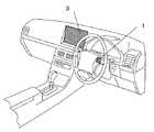
図1はタッチ式入力装置の車両への設置位置を示す模式図である。本実施形態に係わるタッチ式入力装置は、車両に搭載されるナビゲーションシステムに代表される車載端末の入力装置であり、ユーザは図1に示す車両のステアリングに設置されたタッチパッド1とディスプレイ3を用いて操作をおこなう。ユーザはタッチパッド1の表面(操作面)に触れることでポインティングをおこなえ、操作面を押し込むことで決定操作が可能になる。タッチパッド1からの入力信号は図示しない車載端末に取り込まれ、車載端末はタッチパッド1からの信号を基に制御を行い、また、そのフィードバックとしての表示をディスプレイ3に表示する。 FIG. 1 is a schematic diagram showing the installation position of a touch input device on a vehicle. The touch-type input device according to the present embodiment is an input device of an in-vehicle terminal typified by a navigation system mounted on a vehicle, and a user uses a
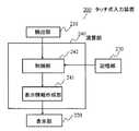
図2は本発明のタッチ式入力装置のブロック構成図である。図2において、タッチ式入力装置200は、検出部210、表示部220、記憶部230、演算部240からなる。演算部240は、表示部220に表示するためのユーザによる操作や情報の入力に必要となる表示情報を作成する表示情報作成部241と、演算部240全体を制御する制御部242とからなる。以下、各部の構成について詳細に説明する。 FIG. 2 is a block diagram of the touch input device of the present invention. In FIG. 2, the touch input device 200 includes a detection unit 210, a
まず、検出部210としては、タッチパッドを用いることができる。図3はタッチパッド1を指5で押している様子を示す模式図である。タッチパッド1を指5で触れた場合、タッチパッド1上の指5が接触している接触面11に対して、接触面11の例えば重心位置12の座標値が演算部240に入力される。ここで、タッチパッド1はその接触位置のタッチパッド面内における座標の絶対位置を出力する。また、本実施形態におけるタッチパッド1はユーザによるタッチパッド1の操作面の押し込み操作を検出できるように、操作面の裏側にスイッチを備えており、押し込み操作を検出するとその検出信号が演算部240に入力される。 First, a touch pad can be used as the detection unit 210. FIG. 3 is a schematic diagram showing a state in which the
表示部220は表示情報作成部241が作成した表示情報を表示するものであり、液晶ディスプレイ、CRT(Cathode Ray Tube)ディスプレイ、EL(Eelectroluminescence)ディスプレイなどが利用できる。図4はディスプレイ3の表示例を示す図であり、本実施形態では、タッチパッド面内の座標位置を、図4に示すディスプレイ3内のボタン表示部31の座標位置に対応させている。よって、図3のように指でタッチパッドに触れた場合、図4のようにボタン表示部31のボタン33がフォーカス(強調表示)されることになる。図4においては、本来表示されない仮想ポインタ34が示されている。仮想ポインタ34は、図3のタッチパッド1上の指5が接触している接触面11の重心位置に対応する点であり、演算部240ではこの仮想ポインタ34を用いて制御をおこなっている。また、図3において指5による押し込み操作を行うことで、図4のボタン33に割当てられた機能の入力がなされ、この場合、例えば表示枠32に「な」の文字が表示される。 The
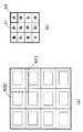
記憶部230には、ディスプレイ3に表示されるボタン表示部31に対応した、演算部240の内部でソフトウェア的に処理が行われる仮想領域300、およびタッチパッドから入力される座標値と仮想領域300との対応関係が記憶されている。図5はその仮想領域300、および仮想領域内に設定されたボタン対応領域302、選択領域303、決定領域304を示している。仮想領域300において、ボタン対応領域302はボタン表示部31内の各ボタン33にそれぞれ対応する領域であり、ボタン対応領域302の内部には選択領域303が設けられている。ここで、選択領域303とは、仮想ポインタの位置がこの領域内にある時に、ボタン表示部31のボタン33がフォーカスされる領域である。 The
また、ボタン対応領域302を包含する領域として決定領域304を設けている。ここで、決定領域304とは、仮想ポインタの位置がこの領域内にあるときに、タッチパッド1をユーザが押し込み操作した際、現在フォーカスされているボタン33に割当てられた機能の入力が決定される領域である。図5では、中央列の上から2行目のボタン対応領域302に対する決定領域304が破線で図示されているが、ボタン対応領域、選択領域、決定領域は表示部31のそれぞれのボタン(本実施形態では12個のボタン)に対応してそれぞれ存在する。なお、ボタン対応領域302、選択領域303、決定領域304の重心位置は一致するように設定されている。指5がタッチパッド1に触れている場合に、仮想領域300内に1点の仮想ポインタ310が現れる。指5がタッチパッド1上を触れながら動き、仮想ポインタ310Aのように選択領域303内に入ったときにボタン表示部31のボタン33にフォーカスがあたり、強調表示される。 In addition, a
演算部240は、典型的にはプロセッサと、各種メモリとを少なくとも含んでおり、例えばROMのようなメモリに格納されたコンピュータプログラムに従って動作する。演算部240は上記コンピュータプログラムを実行することで、表示情報作成部241、制御部242という機能を実行する。 The
表示情報作成部241は、制御部242の指令に基づいて、表示部220に表示する表示情報を作成する。 The display
制御部242は、検出部210から入力される接触位置座標を、記憶部230に記憶されている位置座標の対応関係に基づいて仮想ポインタの座標に変換しする。そして、求めた仮想ポインタの位置座標と、記憶部230に記憶されている、仮想領域との位置関係に基づいて、どのボタンをフォーカスするかを表示情報作成部241に指示する。また、検出部210から押し込み操作の検出信号が入力されると、そのときの仮想ポインタの位置座標と、記憶部230に記憶されている、仮想領域との位置関係に基づいて、どのボタンに割当てられた機能を実行するかを決定する。 The
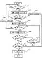
ここで、制御部242の動作について図6のフローチャートを用いて説明する。まず、制御部242は、検知部210であるタッチパッドに接触があったかどうか判断する(ステップS601)。接触があった場合には、タッチパッドから接触位置の座標値が制御部242に入力される。接触がない場合には、元に戻って再び入力を待つ。制御部242は、ステップ501で接触があったと判断すると、入力された座標値を仮想ポインタの位置座標(X,Y)に変換する(ステップ602)。ここで、タッチパッド面内の座標位置と、仮想領域との対応関係は記憶部230に記憶されており、制御部242はその対応関係の基づいて位置座標の変換をおこなう。そして、仮想ポインタの位置座標(X,Y)がいずれかのボタンの選択領域内にあるかどうかを判断し(ステップS603)、選択領域内であれば(Yes)、それに対応するボタンをフォーカス(協調表示)するように表示情報作成部241に指示する(ステップS604)。ステップS603で仮想ポインタの位置座標(X,Y)がいずれかのボタンの選択領域内にないと判断すると(No)、ステップS602に戻る。 Here, the operation of the
次に、ステップS605で制御部242は検知部210であるタッチパッドからの入力に基づいて、タッチパッドへの接触の有無を判断し、接触中であれば(Yes)再度、仮想ポインタの位置座標(X,Y)を入力する(ステップS607)。ユーザがタッチパッドから手を離して、タッチパッドに接触していないと判断すると(ステップ605のNo)、ステップS606でボタンのフォーカスを解除するように表示情報作成部241に指示し、ステップS601に戻る。そして、ステップS608では、検出部210であるタッチパッドから押し込み操作の検知信号があったかどうか判断する。ステップS608で押し込み操作を検知すると(Yes)、ステップS607で入力した仮想ポインタの位置座標(X,Y)が決定領域内にあるかどうかを判断する(ステップS609)。ステップS608で押し込み操作が検知できなかった場合(No)には、仮想ポインタの位置座標(X,Y)が決定領域内にあるかどうかを判断し(ステップS610)、決定領域内にあれば(Yes)、ステップS605に戻る。ステップS610で、仮想ポインタの位置座標(X,Y)が決定領域内にないと判断すると(No)、ボタンのフォーカスを解除するように表示情報作成部241に指示し(ステップS611)、ステップS603に戻る。そして、再度、仮想ポインタの位置座標(X,Y)がいずれかのボタンの選択領域内にあるかどうか判断する。 Next, in step S605, the
一方、ステップ609において、仮想ポインタの位置座標(X,Y)が決定領域内にあると判断されると(Yes)、ステップS612に進んで、対応するボタンに割当てられた機能を実行し、処理を終了する。ステップ609で、仮想ポインタの位置座標(X,Y)が決定領域内にないと判断すると(No)、ボタンのフォーカスを解除するように表示情報作成部241に指示し(ステップS611)、ステップS603に戻る。 On the other hand, if it is determined in
ここで、図6の処理について、図5に示す仮想領域を用いて説明する。仮想ポインタは、一度選択領域内に入ると、決定領域304の外へ出る(図6のステップ610のYes)か、またはユーザーが指5をタッチパッド1から離す(図6のステップ605のNo)まで、ボタン33はフォーカスし続けられる。具体的には、仮想ポインタが一度選択領域303に入ってボタン33がフォーカスされると、仮想ポインタが310Bや310Cの位置へ移動してもボタン33はフォーカスされ続け、ボタン33がフォーカスされている状態で指5による押圧操作がなされた場合(図6のステップS608のYes)には、ボタン33に割当てられた機能の実行が決定される(図6のステップS612)。 Here, the processing of FIG. 6 will be described using the virtual region shown in FIG. Once inside the selection area, the virtual pointer goes out of the determination area 304 (Yes in
よって、ユーザの操作としては、ボタン33にフォーカスをあてようとしたとき、指5をタッチパッド1上で動かし、仮想ポインタを目的のボタン(本実施形態ではボタン33)の選択領域303に移動させる。そして、ユーザには見えない仮想ポインタが目的のボタンの選択領域に入ると目的のボタンがフォーカスされるので、ユーザーは指5の移動を止め、押圧操作をして入力を決定させることになる。 Therefore, as a user operation, when focusing on the
多くの場合、ユーザーは指5を移動させ目的のボタンをフォーカスさせた時点で指の移動を止めるため、ユーザーには見えない仮想ポインタは310Aのように選択領域303の端に近い位置存在することになる。この状態で指5による押圧操作を行った場合、図3に示す接触面11が押圧力により拡大および変形し、重心位置12が移動する。その結果、押圧により決定された時点の仮想ポインタが310Bや310Cの位置に移動してしまう。これが指ぶれである。本実施形態では、目的のボタンの機能が安定して押圧決定なされるように、目的のボタンの決定領域を十分大きくして選択領域を包含するように設定している。決定領域の大きさは、指ぶれにより仮想ポインタが仮想領域300上で移動する距離を考慮して設定することが好ましい。この指ぶれにより仮想ポインタが移動する距離はタッチパッド1の大きさと仮想領域300の大きさおよびタッチパッド1の押圧操作に必要な押圧力や押圧操作時のストロークにも関係する。 In many cases, since the user stops moving the
また、本実施形態では決定領域304はボタン対応領域302を含むように大きくした。前述したように、フォーカスさせた時点では仮想ポインタは選択領域303の端に近い位置存在するので、指ぶれによる仮想ポインタの移動でボタン対応領域302を外れたとしても、決定領域304内であれば目的のボタンの機能が安定して押圧決定なされる。この場合、ユーザが目的のボタンをフォーカスさせるために仮想ポインタを移動させているときに、隣接するボタンへのフォーカスの移動をスムーズにするために、決定領域304は隣接するボタンの選択領域に重ならない様に設定することが好ましい。これは、決定領域304を越えて、はじめて別の選択領域303に移動できるようにしているためである。 In this embodiment, the
従って、仮想ポインタが一旦選択領域に入って、決定操作の指ぶれにより仮想ポインタが少し移動しても、決定領域304は十分大きく設定されているので、仮想ポインタは決定領域内に保持される。その状態で押圧決定動作を行えば目的のボタンに割り当てられた機能を決定することができる。 Therefore, even if the virtual pointer once enters the selection area and the virtual pointer moves slightly due to the finger of the determination operation, the
なお、本実施形態では決定領域304は周囲のボタンの選択領域302に接触するように設定している。このように設定することで、指5を上下左右方向に移動させた際には仮想ポインタが決定領域304から出た瞬間に近接するボタンの選択領域302に入るため、近接するボタンへ連続的にフォーカスが移動できるようになり、どのボタンにもフォーカスされていない状態はなくなる。また、図7に示すように、ボタン34に対しては、決定領域321を近接するボタンの選択領域に接触するように設定してもよい。 In this embodiment, the
さらに、図8に示すように、ボタン表示部31の端部に接するように配置されたボタン(例えばボタン34やボタン35)の仮想領域300における選択領域(例えば選択領域331や選択領域332)は仮想領域300の端部に接するように拡張してもよい。このようにすることで、タッチパッド1の端部を指5が移動している時にボタンをフォーカスさせやすくなる。 Further, as shown in FIG. 8, the selection area (for example, the
また、図9に示すように、ボタン表示部31に表示するボタンはボタン36のようにボタン34よりも小さくし、近接していたボタンとの間に隙間ができるようにしても良い。このようにすることで、タッチパッド1上を指5が移動中、フォーカスが消えるような場合が有ることをボタンとボタンの隙間によってユーザーに伝えることができる。 Further, as shown in FIG. 9, the button displayed on the
さらに、本実施形態においては、選択領域はボタン対応領域の内部に含まれるように小さく設定したが、選択領域はボタン対応領域に一致する大きさでも良い。この場合には、決定領域は選択領域より大きく設定するため、近接するボタンの選択領域に重なってしまうが、フォーカスされているボタンの決定領域が優先されるようにする。このようにすることで、タッチパッド1上を指5が移動した場合に、常にどれかのボタンにフォーカスがあたるようにできる。 Furthermore, in the present embodiment, the selection area is set to be small so as to be included in the button corresponding area, but the selection area may have a size that matches the button corresponding area. In this case, since the determination area is set larger than the selection area, it overlaps with the selection area of the adjacent button, but the determination area of the focused button is given priority. In this way, when the
上記実施の形態で説明した構成は、単に具体例を示すものであり、本願発明の技術的範囲を制限するものではない。本願の効果を奏する範囲において、任意の構成を採用することが可能である。 The configuration described in the above embodiment is merely a specific example and does not limit the technical scope of the present invention. Any configuration can be employed within the scope of the effects of the present application.
本発明のタッチ入力装置は、ボタンを選択して押圧決定する際に指ぶれを起こしても安定して目的のボタンの機能を決定できるという効果を有し、カーナビゲーション、車載情報端末などの車載機器のみならず、コンピュータ、情報機器等の入力装置として有効である。 ADVANTAGE OF THE INVENTION The touch input device of this invention has the effect that it can determine the function of the target button stably even if it raise | generates a finger shake when selecting and pressing a button, Car navigation, a vehicle-mounted information terminal, etc. It is effective as an input device for computers, information devices and the like as well as devices.
1 タッチパッド
3 ディスプレイ
5 指
11 接触面
12 重心位置
31 ボタン表示部
32 表示枠
33 ボタン
200 タッチ式入力装置
210 検出部
220 表示部
230 記憶部
240 演算部
241 表示情報作成部
242 制御部
300 仮想領域
302 ボタン対応領域
303 選択領域
304 決定領域
310A、310B、310C 仮想ポインタDESCRIPTION OF
Claims (3)
Translated fromJapanese前記ユーザにより指示されたタッチパット上の点は、前記表示装置に表示される複数のボタンを含む仮想領域内の仮想ポインタとして対応付けられており、
前記仮想領域において各前記ボタンには、選択領域と、前記選択領域を包含する決定領域がそれぞれ設定されており、
前記仮想領域において各前記ボタンには、前記表示装置に表示される複数のボタンの位置関係に対応して、前記選択領域を包含するボタン対応領域がそれぞれ設定されており、
前記仮想ポインタがいずれかの選択領域内に入ると該選択領域に対応するボタンを選択し、前記仮想ポインタが前記選択されたボタンに対応する決定領域内にある状態で前記タッチパッドの押圧操作を検出すると前記選択を決定する制御部と、
前記制御部からの指示に基づいて前記表示装置に表示する情報を作成する表示情報作成部とを備え、
前記制御部は、いずれかのボタンを選択中の場合に、前記表示装置に表示される前記選択中のボタンを強調表示するように前記表示情報作成部に指示することを特徴とするタッチ式入力装置。A touch-type input device that selects any one of a plurality of buttons displayed on a display device by a touchpad operation by a user, and determines the selection based on a pressing operation of the touchpad,
A point on the touch pad instructed by the user is associated as a virtual pointer in a virtual area including a plurality of buttons displayed on the display device,
In each of the buttons in the virtual area, a selection area and a determination area including the selection area are set, respectively.
In each of the buttons in the virtual area, a button corresponding area including the selection area is set corresponding to the positional relationship of a plurality of buttons displayed on the display device,
When the virtual pointer enters one of the selection areas, the button corresponding to the selection area is selected, and the touch pad is pressed while the virtual pointer is in the determination area corresponding to the selected button. A control unit that determines the selection upon detection;
E Bei a display information creation unit for creating information to be displayed on the display device based on an instruction from the controlunit,
The touch input, wherein the control unit instructs the display information creation unit to highlight the selected button displayed on the display device when any button is selected. apparatus.
Priority Applications (1)
| Application Number | Priority Date | Filing Date | Title |
|---|---|---|---|
| JP2007101531AJP4924164B2 (en) | 2007-04-09 | 2007-04-09 | Touch input device |
Applications Claiming Priority (1)
| Application Number | Priority Date | Filing Date | Title |
|---|---|---|---|
| JP2007101531AJP4924164B2 (en) | 2007-04-09 | 2007-04-09 | Touch input device |
Publications (2)
| Publication Number | Publication Date |
|---|---|
| JP2008257629A JP2008257629A (en) | 2008-10-23 |
| JP4924164B2true JP4924164B2 (en) | 2012-04-25 |
Family
ID=39981111
Family Applications (1)
| Application Number | Title | Priority Date | Filing Date |
|---|---|---|---|
| JP2007101531AActiveJP4924164B2 (en) | 2007-04-09 | 2007-04-09 | Touch input device |
Country Status (1)
| Country | Link |
|---|---|
| JP (1) | JP4924164B2 (en) |
Families Citing this family (9)
| Publication number | Priority date | Publication date | Assignee | Title |
|---|---|---|---|---|
| JP5225820B2 (en)* | 2008-11-25 | 2013-07-03 | アイシン精機株式会社 | Input device, vehicle periphery monitoring device, icon switch selection method and program |
| JP5269648B2 (en)* | 2009-03-02 | 2013-08-21 | パナソニック株式会社 | Portable terminal device and input device |
| JP5527304B2 (en)* | 2011-10-17 | 2014-06-18 | 株式会社デンソー | Input device |
| US20130127738A1 (en)* | 2011-11-23 | 2013-05-23 | Microsoft Corporation | Dynamic scaling of touch sensor |
| JP5689867B2 (en) | 2012-10-26 | 2015-03-25 | 株式会社東海理化電機製作所 | Touch input device |
| JP5572851B1 (en)* | 2013-02-26 | 2014-08-20 | パナソニック インテレクチュアル プロパティ コーポレーション オブ アメリカ | Electronics |
| WO2015054362A1 (en)* | 2013-10-08 | 2015-04-16 | Tk Holdings Inc. | Force-based touch interface with ingrated multi-sensory feedback |
| WO2017033605A1 (en)* | 2015-08-26 | 2017-03-02 | オリンパス株式会社 | Touch panel device and endoscope system |
| JP7625895B2 (en) | 2021-02-26 | 2025-02-04 | 京セラドキュメントソリューションズ株式会社 | Operation input device and image forming device |
Family Cites Families (3)
| Publication number | Priority date | Publication date | Assignee | Title |
|---|---|---|---|---|
| JP4148187B2 (en)* | 2004-06-03 | 2008-09-10 | ソニー株式会社 | Portable electronic device, input operation control method and program thereof |
| JP2006215963A (en)* | 2005-02-07 | 2006-08-17 | Tokai Rika Co Ltd | Touch type input device |
| JP2006244393A (en)* | 2005-03-07 | 2006-09-14 | Tokai Rika Co Ltd | Input device |
- 2007
- 2007-04-09JPJP2007101531Apatent/JP4924164B2/enactiveActive
Also Published As
| Publication number | Publication date |
|---|---|
| JP2008257629A (en) | 2008-10-23 |
Similar Documents
| Publication | Publication Date | Title |
|---|---|---|
| JP4924164B2 (en) | Touch input device | |
| JP5295328B2 (en) | User interface device capable of input by screen pad, input processing method and program | |
| EP2256614B1 (en) | Display control apparatus, display control method, and computer program | |
| JP4734435B2 (en) | Portable game device with touch panel display | |
| JP5808712B2 (en) | Video display device | |
| JP5640486B2 (en) | Information display device | |
| JP5371798B2 (en) | Information processing apparatus, information processing method and program | |
| JP2006072854A (en) | Input device | |
| US20120218308A1 (en) | Electronic apparatus with touch screen and display control method thereof | |
| JP3850570B2 (en) | Touchpad and scroll control method using touchpad | |
| JP2012099005A (en) | Input device, input method, and input program | |
| JPH1124841A (en) | Information processing apparatus, processing method, and storage medium | |
| EP1376324A2 (en) | Information processing apparatus and character input assisting method for use in the same | |
| WO2018123320A1 (en) | User interface device and electronic apparatus | |
| JP4856136B2 (en) | Movement control program | |
| KR101422060B1 (en) | Information display apparatus and method for vehicle using touch-pad, and information input module thereof | |
| US8731824B1 (en) | Navigation control for a touch screen user interface | |
| KR101480775B1 (en) | Information display apparatus and method for vehicle using touch-pad, and information input module thereof | |
| JP2018023792A (en) | GAME DEVICE AND PROGRAM | |
| KR101311832B1 (en) | Mobile phone cover and mobile phone having the same | |
| CN102650926B (en) | Electronic device with touch screen and display control method thereof | |
| JP6126639B2 (en) | A portable game device having a touch panel display and a game program. | |
| JP2014155856A (en) | Portable game device including touch panel-type display | |
| JP2020027307A (en) | Input device | |
| JP5027084B2 (en) | Input device and input method |
Legal Events
| Date | Code | Title | Description |
|---|---|---|---|
| A621 | Written request for application examination | Free format text:JAPANESE INTERMEDIATE CODE: A621 Effective date:20100330 | |
| RD01 | Notification of change of attorney | Free format text:JAPANESE INTERMEDIATE CODE: A7421 Effective date:20100413 | |
| A977 | Report on retrieval | Free format text:JAPANESE INTERMEDIATE CODE: A971007 Effective date:20110728 | |
| A131 | Notification of reasons for refusal | Free format text:JAPANESE INTERMEDIATE CODE: A131 Effective date:20110809 | |
| A521 | Request for written amendment filed | Free format text:JAPANESE INTERMEDIATE CODE: A523 Effective date:20110922 | |
| TRDD | Decision of grant or rejection written | ||
| A01 | Written decision to grant a patent or to grant a registration (utility model) | Free format text:JAPANESE INTERMEDIATE CODE: A01 Effective date:20120110 | |
| A01 | Written decision to grant a patent or to grant a registration (utility model) | Free format text:JAPANESE INTERMEDIATE CODE: A01 | |
| A61 | First payment of annual fees (during grant procedure) | Free format text:JAPANESE INTERMEDIATE CODE: A61 Effective date:20120123 | |
| FPAY | Renewal fee payment (event date is renewal date of database) | Free format text:PAYMENT UNTIL: 20150217 Year of fee payment:3 | |
| R151 | Written notification of patent or utility model registration | Ref document number:4924164 Country of ref document:JP Free format text:JAPANESE INTERMEDIATE CODE: R151 | |
| FPAY | Renewal fee payment (event date is renewal date of database) | Free format text:PAYMENT UNTIL: 20150217 Year of fee payment:3 | |
| S533 | Written request for registration of change of name | Free format text:JAPANESE INTERMEDIATE CODE: R313533 | |
| S111 | Request for change of ownership or part of ownership | Free format text:JAPANESE INTERMEDIATE CODE: R313113 | |
| R350 | Written notification of registration of transfer | Free format text:JAPANESE INTERMEDIATE CODE: R350 |