JP4922463B1 - Telephone terminal, communication device, and terminal maintenance method - Google Patents
Telephone terminal, communication device, and terminal maintenance methodDownload PDFInfo
- Publication number
- JP4922463B1 JP4922463B1JP2011076286AJP2011076286AJP4922463B1JP 4922463 B1JP4922463 B1JP 4922463B1JP 2011076286 AJP2011076286 AJP 2011076286AJP 2011076286 AJP2011076286 AJP 2011076286AJP 4922463 B1JP4922463 B1JP 4922463B1
- Authority
- JP
- Japan
- Prior art keywords
- address
- electronic device
- unit
- telephone terminal
- network system
- Prior art date
- Legal status (The legal status is an assumption and is not a legal conclusion. Google has not performed a legal analysis and makes no representation as to the accuracy of the status listed.)
- Expired - Fee Related
Links
Images


Classifications
- H—ELECTRICITY
- H04—ELECTRIC COMMUNICATION TECHNIQUE
- H04M—TELEPHONIC COMMUNICATION
- H04M1/00—Substation equipment, e.g. for use by subscribers
- H04M1/24—Arrangements for testing
Landscapes
- Engineering & Computer Science (AREA)
- Signal Processing (AREA)
- Data Exchanges In Wide-Area Networks (AREA)
- Small-Scale Networks (AREA)
- Telephone Function (AREA)
- Telephonic Communication Services (AREA)
Abstract
Translated fromJapaneseDescription
Translated fromJapanese本発明の実施形態は、IP(Internet Protocol)ネットワークを利用して電話通信を実現する電話端末、通信デバイス、および端末保守方法に関する。 Embodiments described herein relate generally to a telephone terminal, a communication device, and a terminal maintenance method for realizing telephone communication using an IP (Internet Protocol) network.
IPネットワークを介して音声パケットを伝送する電話システムが発展してきている。この種のシステムはVoIP(Voice over IP)などと称され、近年の電話システムの主流になってきている。
この種のシステムにおける電話端末はIP電話機などと称され、LAN(Local Area Network)などのネットワークシステムに接続して使用される。IP電話機は多種多様な機能を備えており、必要に応じて保守を行なう必要がある。保守に係わる作業には、例えばIP電話機に係わるソフトウェア/ファームウェアのアップデートや通話ログの取り出し、あるいは不具合が生じたときの復旧作業などがある。Telephone systems that transmit voice packets over an IP network have been developed. This type of system is called VoIP (Voice over IP) or the like, and has become a mainstream telephone system in recent years.
A telephone terminal in this type of system is called an IP telephone or the like, and is used by connecting to a network system such as a LAN (Local Area Network). IP telephones have various functions and need to be maintained as necessary. The work related to maintenance includes, for example, software / firmware update and call log retrieval related to the IP telephone, or recovery work when a malfunction occurs.
保守に際してはIP電話機に専用のパーソナルコンピュータ(PC)を接続し、この保守用PCを用いて作業を行なうことが多い。このような形態において以下(1)、(2)のような不便のあることが知られている。 In maintenance, a dedicated personal computer (PC) is connected to the IP telephone and work is often performed using the maintenance PC. It is known that the following inconveniences (1) and (2) exist in such a form.
(1) 保守用PCをネットワークシステムに接続し、ネットワークシステムを経由して保守対象のIP電話機にアクセスして保守を行なう形態がある。この形態では保守用PCとIP電話機との間でデータをダウンロード/アップロードする際に、データパケットがネットワークシステムを流れることになる。よってデータパケットのトラフィックが音声パケットのトラフィックを圧迫し、通話に雑音などが生じて通話品質が劣化する。 (1) There is a form in which a maintenance PC is connected to a network system, and maintenance is performed by accessing the maintenance target IP phone via the network system. In this mode, when data is downloaded / uploaded between the maintenance PC and the IP telephone, data packets flow through the network system. Therefore, the data packet traffic compresses the voice packet traffic, and noise or the like is generated in the call, thereby degrading the call quality.
(2) IP電話機に備わるハブ機能を利用し、保守対象のIP電話機のハブのポートに保守用PCを接続するもう一つの形態がある。この形態では、保守用PCのIPアドレスの定期的リフレッシュなどの観点から、IP電話機をネットワークシステムに常時接続しておく必要がある。保守作業時においては呼(call)の到来を防ぐためにIP電話機をネットワークシステムから切り離しておきたいが、(2)の形態では((1)の形態においても)それができない。 (2) There is another mode in which a maintenance PC is connected to a hub port of an IP telephone to be maintained using a hub function provided in the IP telephone. In this form, it is necessary to always connect the IP telephone to the network system from the viewpoint of periodically refreshing the IP address of the maintenance PC. In maintenance work, it is desirable to disconnect the IP telephone from the network system in order to prevent the arrival of a call. However, in the form (2), this is not possible (even in the form (1)).
IP電話機の保守作業にあたってはデータトラフィックがネットワークシステムを流れないようにしたい。また、IP電話機とネットワークシステムとの間を一時的に切断できるようにしたい。このような形態での保守を、複雑な設定やシステムの改変を伴うことなく、簡易に実施できるようにしたシステムの開発が待たれている。
目的は、保守作業を簡易にできるようにした電話端末、通信デバイスおよび端末保守方法を提供することにある。I want to prevent data traffic from flowing through the network system during IP telephone maintenance. Also, I want to be able to temporarily disconnect between the IP phone and the network system. Development of a system that can easily perform maintenance in such a form without complicated settings or system modifications is awaited.
An object is to provide a telephone terminal, a communication device, and a terminal maintenance method capable of simplifying maintenance work.
実施形態によれば、DHCP(Dynamic Host Configuration Protocol)サーバを備えるネットワークシステムに接続される電話端末は、リピータハブと、取得部と、割り当て部と、通信部とを具備する。リピータハブは、ネットワークシステムに接続されるネットワークポートと、電子機器に接続されるポートとを備える。取得部は、DHCPサーバから電話端末用の第1のIP(Internet Protocol)アドレスと、電子機器用の第2のIPアドレスとを取得する。割り当て部は、電子機器からのIPアドレス割り当て要求に応じて、第2のIPアドレスを要求元の電子機器に割り当てる。通信部は、第1のIPアドレスと、電子機器に割り当てられたIPアドレスとを用いて当該電子機器と通信する。 According to the embodiment, a telephone terminal connected to a network system including a Dynamic Host Configuration Protocol (DHCP) server includes a repeater hub, an acquisition unit, an allocation unit, and a communication unit. The repeater hub includes a network port connected to the network system and a port connected to the electronic device. The acquisition unit acquires a first IP (Internet Protocol) address for a telephone terminal and a second IP address for an electronic device from a DHCP server. The assigning unit assigns the second IP address to the requesting electronic device in response to an IP address assignment request from the electronic device. The communication unit communicates with the electronic device using the first IP address and the IP address assigned to the electronic device.
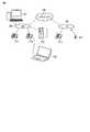
図1は、実施形態に係わる電話システムの一例を示す図である。この例ではIPネットワーク100を利用して音声通話を行う、いわゆるVoIPを想定する。図1に示されるようなシステムにおける呼接続処理プロトコルはSIP(Session Initiation Protocol)が代表的であるが、これに限らずMegaco(Media Gateway Control)、あるいはH.323などのプロトコルも同様に利用できる。 FIG. 1 is a diagram illustrating an example of a telephone system according to an embodiment. In this example, what is called VoIP in which voice communication is performed using the
図1において、IPネットワーク100に複数のLAN(Local Area Network)200,300が接続される。各LAN200,300には端末装置としてのIP電話機(IP Terminal:IPT)が接続される。LAN200,300は例えば企業内などのローカルエリアに敷設されたネットワークシステムである。 In FIG. 1, a plurality of LANs (Local Area Networks) 200 and 300 are connected to an
例えばLAN200にはDHCP(Dynamic Host Configuration Protocol)サーバ201およびSIPサーバ202が接続される。DHCPサーバ201は、IPネットワーク(LAN200,300を含む)におけるIPアドレスの割り当てに係わる処理を担うサーバである。すなわちIPT−1,IPT−2は、DHCPサーバを備えるネットワークシステムに接続される。IPT−3,IPT−4もその範疇に含めることが可能である。SIPサーバは、クライアント間でのピア・ツウ・ピアまたはSIPサーバを介したセッション形成に係わる処理を担うサーバである。 For example, a DHCP (Dynamic Host Configuration Protocol)
IPT−1〜IPT−4はエンベデッドに構成されたIP電話端末のほか、移動通信端末、あるいは電話機能をインストールしたコンピュータ(いわゆるソフトフォン)などであってよい。 IPT-1 to IPT-4 may be an IP telephone terminal configured in an embedded manner, a mobile communication terminal, or a computer (so-called soft phone) in which a telephone function is installed.
このような構成において、保守を行うため、IPT−2に保守用PC400が接続される場合を想定する。このケースでは、IPT−2と保守用PC400とで授受される、保守に関する情報がネットワーク上に流れることを防ぐために、IPT−2とネットワークシステム(LAN200)とのリンクが切断されているのが好ましい。実施形態ではこの設定を簡易に実現可能な手法につき説明する。 In such a configuration, it is assumed that a maintenance PC 400 is connected to IPT-2 for maintenance. In this case, it is preferable that the link between the IPT-2 and the network system (LAN 200) is disconnected in order to prevent maintenance-related information exchanged between the IPT-2 and the maintenance PC 400 from flowing on the network. . In the embodiment, a method capable of easily realizing this setting will be described.
図2は、図1に示されるIPTの実施の形態を示す機能ブロック図である。図2においては例えばIPT−2の機能ブロックを示すが、他のIPT−1、IPT−3、IPT−4も同様である。
IPT−2は、表示器40と、リピータハブ(HUB)41と、制御部42と、キーパッド部43と、メモリ44とを備える。このうち表示器40は、例えばLCD(Liquid Crystal Display)であり、種々のメッセージを視覚的に表示する。キーパッド部43はソフトキーや数字キーなどを備え、ユーザの入力操作を受け付ける。FIG. 2 is a functional block diagram showing an embodiment of the IPT shown in FIG. In FIG. 2, for example, functional blocks of IPT-2 are shown, but the same applies to other IPT-1, IPT-3, and IPT-4.
The IPT-2 includes a
リピータハブ41は、LANケーブルなどを介してネットワークシステムに接続されるネットワークポート41aと、電子機器としての保守用PC400に接続されるポート41bとを備える。すなわちリピータハブ41は、或るポートから受信したデータを他のポートに送信する機能(ハブ機能)を備える。この機能はいわゆるレイヤ1スイッチにより実現されるもので、データパケットをポート間で透過的に通過させるという機能である。 The
メモリ44は、例えばフラッシュメモリなどの書き換え可能な半導体記憶デバイスである。メモリ44はその記憶領域に、端末IPアドレス44aと、第2IPアドレス44bと、ローカルIPアドレス44cと、管理テーブル44dとを記憶する。端末IPアドレス44aは、DHCPサーバ201から取得した、自端末用のIPアドレスである。第2IPアドレス44bは、リピータハブ41を介して接続される保守用PC400が通信を行うために、DHCPサーバ201から取得するIPアドレスである。ローカルIPアドレス44cは、IPTと保守用PC400との間での通信のために用いられるアドレスである。このローカルIPアドレス44cは上記ケースにおいて保守用PC400に割り当てられる。管理テーブル44dについては図3を用いて後述する。 The
制御部42は、この実施形態に係わる処理機能として、取得部42aと、割り当て部42bと、通信部42cと、判定部42dと、認識部42eとを備える。
取得部42aは、DHCPサーバ201から端末IPアドレス44aと、第2IPアドレスとを取得し、これらをメモリ44に記憶する。The
The
通信部42cは、端末IPアドレスと、保守用PC400に割り当てられたIPアドレスとを用いて保守用PC400と通信する。この通信により、例えばIPTの保守に係わるデータのダウンロード/アップロードが保守用PC400との間で実行される。判定部42dは、メモリ44の管理テーブル44dの内容を参照して、第2IPアドレスの使用の可否を判定する。この判定の結果、第2IPアドレスが使用不可であれば、割り当て部42bは、ローカルIPアドレスを要求元である保守用PC400に割り当てる。 The
認識部42eは、ネットワークポート41aを介するネットワークシステムとのリンクを認識する。簡単に言えば、例えばLANケーブルがネットワークポート41aに接続されているか否かで認識部42eはリンクの接続/切断を認識することができる。 The
割り当て部42bは、保守用PC400からのIPアドレス割り当て要求に応じて、前記第2のIPアドレスを要求元である保守用PC400に割り当てる。割り当て部42bは、認識部42eによりリンクが接続されていることが認識されれば、自らの機能を停止する。このような処理はソフトウェア作成時のコーディングで容易に可能である。 In response to an IP address assignment request from the
図3は、管理テーブル44dにおいて管理される内容の一例を示す図である。図3に示すように管理テーブル44dにおいては、端末IPアドレスの割り当ての可否(成否)と、そのIPアドレスの具体的な内容、および有効期限が記載される。同様に管理テーブル44dにおいては、第2IPアドレスの割り当ての可否(成否)と、そのIPアドレスの具体的な内容、および有効期限が記載される。つまり管理テーブル44aは、DHCPサーバ201による割り当ての成否と、有効期限(リース期限)とを、端末IPアドレス、第2IPアドレスごとに管理するためのテーブルである。次に、上記構成における作用を説明する。 FIG. 3 is a diagram illustrating an example of contents managed in the management table 44d. As shown in FIG. 3, the management table 44d describes whether or not a terminal IP address can be assigned (success / failure), the specific contents of the IP address, and the expiration date. Similarly, in the management table 44d, whether or not the second IP address can be allocated (success / failure), the specific contents of the IP address, and the expiration date are described. That is, the management table 44a is a table for managing the success / failure of allocation by the
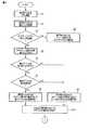
図4は、実施形態におけるIP電話機(IPT)の処理手順の一例を示すフローチャートである。なおIPTのIPアドレスである端末IPアドレス44aは既に割り当てられているとする。 FIG. 4 is a flowchart illustrating an example of a processing procedure of the IP telephone (IPT) in the embodiment. It is assumed that the
図4において、IPTに保守用PC400が接続されると(ブロックS1)、IPTは、IPTと保守用PC400との間のリンクを確認する(ブロックS2)。次にIPTは、IPTとネットワークシステムとのリンクを認識する(ブロックS3)。ここでネットワークシステムとのリンクが認識されれば(Yes)、保守用PC400が使用するIPアドレスの割り当ては、DHCPサーバ201が行うことなる(ブロックS4)。 In FIG. 4, when the
保守用PC400にIPアドレスが割り当てられれば、保守用PC400はIPTと通信することが可能になる。なお上記リンクが認識された状態では、保守用PC400は、IPTのリピータハブ41を介してネットワークシステム上での通信を行うことも可能である。 If an IP address is assigned to
ブロックS3でネットワークシステムとのリンクが認識されなければ(No)、IPTは、割り当て部42bを起動する(ブロックS5)。これにより、保守用PC400へのIPアドレスの付与は、DHCPサーバ201に代わり、割り当て部42bが行うようになる。
この状態で、保守用PC400からIPアドレス割り当て要求を受けると、IPTは、DHCPサーバ201によるIPアドレスの割り当てが完了しているか否かを確認する。詳しくは、IPTは第2IPアドレス44bが、DHCPサーバ201から割り当てられているか否かを判定する(ブロックS6)。ブロックS6でYesであれば、IPTは、割り当てられた第2IPアドレス44bがその時点で有効期限内にあるか否かを判定する(ブロックS7)。If the link with the network system is not recognized in block S3 (No), the IPT activates the assigning
In this state, upon receiving an IP address assignment request from the
ブロックS6またはブロックS7においてNoであれば、IPTの割り当て部42bは、保守用PC400からのIPアドレス割り当て要求に応じて、IPTと保守用PC400との間で使用するためのローカルIPアドレス44cを保守用PC400に割り当てる(ブロックS8)。
ブロックS7においてYesであれば、IPTの割り当て部42bは、保守用PC400からのIPアドレス割り当て要求に応じて、第2IPアドレス44bを保守用PC400に割り当てる(ブロックS9)。If No in block S6 or block S7, the
If Yes in block S7, the
以上の手順により保守用PC400にユニークなIPアドレスが割り当てられる。これにより、IPTとネットワークシステムとのリンクを切断した状態で、IPTと保守用PC400との間での通信が可能になり、双方向での種々のデータの授受が可能になる。種々のデータにはログデータ、バックアップデータ、設定データ、あるいはIPTのプログラム更新のためのファイルデータなどがある。 A unique IP address is assigned to the
なお端末IPアドレス44aについては、有効期間が過ぎていても、ネットワークシステムとのリンクが認識されるまで、固定的な端末IPアドレス44aを継続して使用するようにする。ネットワークシステムとのリンクが認識されるまで、とは、つまりIPTがネットワークシステムに再接続されるまでである。 As for the
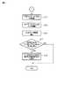
図5は、実施形態におけるIP電話機(IPT)の処理手順の一例を示すフローチャートである。図5においては、図4のフローチャートにおいて保守用PC400にIPアドレスが割り当てられたのち、IPTがネットワークシステムに再接続された後の処理手順が示される。図5の処理手順は、例えば保守に係わるデータの授受が終了したのちIPTを動作状態に戻すために実施される。 FIG. 5 is a flowchart illustrating an example of a processing procedure of the IP telephone (IPT) in the embodiment. FIG. 5 shows a processing procedure after an IP address is assigned to the
IPTがネットワークシステムに再接続されると(ブロックS11)、IPTはネットワークシステムとのリンクを認識する(ブロックS12)。そうするとIPTは割り当て部42bの機能を停止する(ブロックS13)。よってIPTのDHCPサーバ機能は停止される。 When the IPT is reconnected to the network system (block S11), the IPT recognizes the link with the network system (block S12). Then, the IPT stops the function of the assigning
次にIPTは、保守用PC400に対してローカルIPアドレス44cが割り当てられているか否かを判定する(ブロックS14)。ここでYesであれば、IPTはローカルIPアドレス44cの取り消しを保守用PC400に要求する(ブロックS15)。これを受けて保守用PC400は、改めてIPアドレスの割り当て要求を送信する。 Next, the IPT determines whether or not the
保守用PC400から送信されたIPアドレス割り当て要求は、IPTのリピータハブ41を経由して、ネットワークシステムのDHCPサーバ201により受信される。このIPアドレス割り当て要求に応じて、DHCPサーバ201はIPアドレスの割り当てを行う。すなわちIPアドレスの割り当ては、IPTの割り当て部42bよりもDHCPサーバ201が優先されることになる。
なお端末IPアドレス44aの有効期間が過ぎていれば、ネットワークシステムとのリンクが認識されたのち、IPTもIPアドレスの割り当てをDHCPサーバ201に対して改めて要求する。The IP address assignment request transmitted from the
If the validity period of the
実施形態では、IPTは自身のIPアドレス(端末IPアドレス)に加えて、IPTに接続される保守用PC400が使用するための少なくとももう1つのIPアドレス(第2IPアドレス)の取得をDHCPサーバ201に要求する。そして、IPTは、ネットワーク上のDHCPサーバ201から、各IPアドレスが割り当てられたかどうか、割り当てられたならば有効期限を過ぎているか否か、を管理する。
さらにIPTは、ネットワークポート41a上のリンク状態、ポート41b上のリンク状態を個別に認識し、その結果と、上記管理の結果に基づいて、保守用PC400へのIPアドレスの割り当てを制御する。In the embodiment, in addition to its own IP address (terminal IP address), the IPT acquires to the
Further, the IPT individually recognizes the link state on the
以上のようにしたので、保守用PC400をIPTに接続した際に、保守用PC400とIPTとの通信を簡易に行うことができ、かつ、データトラフィックがネットワークシステムを流れない形態で実施できるようになる。さらには、IPTとネットワークシステムとのリンクの有無に応じて、IPTによるIPアドレス割り当て機能を起動/停止するようにしているので、保守用PC400に対するIPアドレスの割り当てを、DHCPサーバ201の存在を考慮したかたちで実施することが可能になる。従って、IPTにより他のクライアントにIPアドレスが割り当てられることを防止できる。これらのことから、保守作業を簡易にできるようにした電話端末、端末保守方法を提供することが可能となる。 As described above, when the
なお本発明は上記実施形態に限定されるものではない。
図6は、実施形態に係わる通信デバイスの一例を示す機能ブロック図である。図6には、VoIP機能を備えていない標準の電話機(符合6を付して普通電話機と称する)を、ネットワークシステムに接続する通信デバイスの一例が示される。この通信デバイスをアダプタ500と称する。The present invention is not limited to the above embodiment.
FIG. 6 is a functional block diagram illustrating an example of a communication device according to the embodiment. FIG. 6 shows an example of a communication device that connects a standard telephone (noted with reference numeral 6 and called a normal telephone) having no VoIP function to the network system. This communication device is referred to as an
アダプタ500は、普通電話機6にVoIP通信機能を提供する。具体的には、アダプタ500は、普通電話機6を収容する機能、普通電話機6の操作により電話システムへのシグナリングプロトコルを起動する機能、受信したシグナリングメッセージにより普通電話機6の呼び出し音などを鳴らす機能(着信通知機能)、ネットワークシステム上で授受される音声パケットを普通電話機6に中継する機能などを備える。 The
アダプタ500は、図2に示すリピータハブ41と、制御部42と、メモリ44とを備える。特にリピータハブ41は、ネットワークポート41a、ポート41bに加え、普通電話機6に接続されるポート41cを備える。このような構成により、保守作業を簡易にできるようにした通信デバイスを提供することが可能となる。 The
なお、本発明は上記実施形態そのままに限定されるものではなく、実施段階ではその要旨を逸脱しない範囲で構成要素を変形して具体化できる。また、上記実施形態に開示されている複数の構成要素の適宜な組み合せにより種々の発明を形成できる。例えば、実施形態に示される全構成要素から幾つかの構成要素を削除してもよい。更に、異なる実施形態に亘る構成要素を適宜組み合せてもよい。 Note that the present invention is not limited to the above-described embodiment as it is, and can be embodied by modifying the constituent elements without departing from the scope of the invention in the implementation stage. Further, various inventions can be formed by appropriately combining a plurality of constituent elements disclosed in the embodiment. For example, some components may be deleted from all the components shown in the embodiment. Furthermore, you may combine suitably the component covering different embodiment.
100…IPネットワーク、200,300…LAN、IPT−1,IPT−2,IPT−3,IPT−4…IP電話機、201…DHCPサーバ、202…SIPサーバ、400…保守用PC、40…表示器、41…リピータハブ(HUB)、41a…ネットワークポート、41b,41c…ポート、42…制御部、42a…取得部、42b…割り当て部、42c…通信部、42d…判定部、42e…認識部、43…キーパッド部、44…メモリ、44a…端末IPアドレス、44b…第2IPアドレス、44c…ローカルIPアドレス、44d…管理テーブル、500…アダプタ、6…普通電話機 DESCRIPTION OF
Claims (6)
Translated fromJapanese前記ネットワークシステムに接続されるネットワークポートと、電子機器に接続されるポートとを備えるリピータハブと、
前記DHCPサーバから前記電話端末用の第1のIP(Internet Protocol)アドレスと、前記電子機器用の第2のIPアドレスとを取得する取得部と、
前記第2のIPアドレスの割り当ての成否と、当該第2のIPアドレスの有効期限と、第3のIPアドレスとを記憶する記憶部と、
前記記憶部の記憶内容を参照して前記第2のIPアドレスの使用の可否を判定する判定部と、
前記電子機器からのIPアドレス割り当て要求に応じて、前記第2のIPアドレスを要求元の電子機器に割り当て、前記判定部による判定の結果前記第2のIPアドレスが使用不可であれば、前記第3のIPアドレスを前記要求元の電子機器に割り当てる割り当て部と、
前記第1のIPアドレスと、前記電子機器に割り当てられたIPアドレスとを用いて当該電子機器と通信する通信部とを具備する、電話端末。In a telephone terminal connected to a network system including a DHCP (Dynamic Host Configuration Protocol) server,
A repeater hub comprising a network port connected to the network system and a port connected to an electronic device;
An obtaining unit for obtaining a first IP (Internet Protocol) address for the telephone terminal and a second IP address for the electronic device from the DHCP server;
A storage unit for storing success or failure of the assignment of the second IP address, an expiration date of the second IP address, and a third IP address;
A determination unit that determines whether or not the second IP address can be used with reference to the storage content of the storage unit;
In response to an IP address assignment request from the electronic device, the second IP address is assigned to the requesting electronic device. An assigning unitthat assigns the IP address of 3 to the requesting electronic device ;
A telephone terminal comprising: a communication unit that communicates with the electronic device using the first IP address and the IP address assigned to the electronic device.
前記割り当て部は、前記認識部により前記リンクが認識されれば、当該割り当て部の機能を停止する、請求項1に記載の電話端末。And a recognition unit for recognizing a link with the network system via the network port,
The telephone terminal according to claim 1, wherein the allocating unit stops the function of the allocating unit when the recognizing unit recognizes the link .
前記ネットワークシステムに接続されるネットワークポートと、電子機器に接続されるポートと、前記電話端末に接続されるポートとを備えるリピータハブと、
前記DHCPサーバから前記通信デバイス用の第1のIP(Internet Protocol)アドレスと、前記電子機器用の第2のIPアドレスとを取得する取得部と、
前記第2のIPアドレスの割り当ての成否と、当該第2のIPアドレスの有効期限と、第3のIPアドレスとを記憶する記憶部と、
前記記憶部の記憶内容を参照して前記第2のIPアドレスの使用の可否を判定する判定部と、
前記電子機器からのIPアドレス割り当て要求に応じて、前記第2のIPアドレスを要求元の電子機器に割り当て、前記判定部による判定の結果前記第2のIPアドレスが使用不可であれば、前記第3のIPアドレスを前記要求元の電子機器に割り当てる割り当て部と、
前記第1のIPアドレスと、前記電子機器に割り当てられたIPアドレスとを用いて当該電子機器と通信する通信部とを具備する、通信デバイス。In a communication device connected to a network system including a DHCP (Dynamic Host Configuration Protocol) server and connecting a telephone terminal to the network system,
A repeater hub comprising a network port connected to the network system, a port connected to an electronic device, and a port connected to the telephone terminal;
An obtaining unit for obtaining a first IP (Internet Protocol) address for the communication device and a second IP address for the electronic device from the DHCP server;
A storage unit for storing success or failure of the assignment of the second IP address, an expiration date of the second IP address, and a third IP address;
A determination unit that determines whether or not the second IP address can be used with reference to the storage content of the storage unit;
In response to an IP address assignment request from the electronic device, the second IP address is assigned to the requesting electronic device. An assigning unitthat assigns the IP address of 3 to the requesting electronic device ;
A communication device comprising: a communication unit that communicates with the electronic device using the first IP address and an IP address assigned to the electronic device.
前記割り当て部は、前記認識部により前記リンクが認識されれば、当該割り当て部の機能を停止する、請求項3に記載の通信デバイス。The communication device according to claim 3, wherein the allocation unit stops the function of the allocation unit when the link is recognized by the recognition unit.
前記電話端末は、前記ネットワークシステムに接続されるネットワークポートと、電子機器に接続されるポートとを備えるリピータハブを具備し、The telephone terminal includes a repeater hub including a network port connected to the network system and a port connected to an electronic device,
前記電話端末が、前記DHCPサーバから前記電話端末用の第1のIP(Internet Protocol)アドレスと、前記電子機器用の第2のIPアドレスとを取得し、The telephone terminal obtains a first IP (Internet Protocol) address for the telephone terminal and a second IP address for the electronic device from the DHCP server;
前記電話端末が、前記第2のIPアドレスの割り当ての成否と、当該第2のIPアドレスの有効期限と、第3のIPアドレスとを記憶部に記憶し、The telephone terminal stores the success or failure of the assignment of the second IP address, the expiration date of the second IP address, and the third IP address in a storage unit,
前記電話端末が、前記記憶部の記憶内容を参照して前記第2のIPアドレスの使用の可否を判定し、The telephone terminal determines whether or not the second IP address can be used with reference to the storage content of the storage unit;
前記電話端末が、前記電子機器からのIPアドレス割り当て要求に応じて、前記第2のIPアドレスを要求元の電子機器に割り当て、前記判定の結果前記第2のIPアドレスが使用不可であれば、前記第3のIPアドレスを前記要求元の電子機器に割り当て、In response to an IP address assignment request from the electronic device, the telephone terminal assigns the second IP address to a requesting electronic device, and if the second IP address is unusable as a result of the determination, Assigning the third IP address to the requesting electronic device;
前記電話端末が、前記第1のIPアドレスと、前記電子機器に割り当てられたIPアドレスとを用いて当該電子機器と通信する、端末保守方法。A terminal maintenance method in which the telephone terminal communicates with the electronic device using the first IP address and an IP address assigned to the electronic device.
前記電話端末が、前記リンクが認識されれば、前記割り当てることを停止する、請求項5に記載の端末保守方法。The telephone terminal recognizes a link with the network system via the network port;
The terminal maintenance method according to claim 5, wherein the telephone terminal stops the assignment if the link is recognized .
Priority Applications (2)
| Application Number | Priority Date | Filing Date | Title |
|---|---|---|---|
| JP2011076286AJP4922463B1 (en) | 2011-03-30 | 2011-03-30 | Telephone terminal, communication device, and terminal maintenance method |
| US13/229,265US20120250667A1 (en) | 2011-03-30 | 2011-09-09 | Phone Terminal, Communication Device, and Terminal Maintenance Method |
Applications Claiming Priority (1)
| Application Number | Priority Date | Filing Date | Title |
|---|---|---|---|
| JP2011076286AJP4922463B1 (en) | 2011-03-30 | 2011-03-30 | Telephone terminal, communication device, and terminal maintenance method |
Publications (2)
| Publication Number | Publication Date |
|---|---|
| JP4922463B1true JP4922463B1 (en) | 2012-04-25 |
| JP2012212959A JP2012212959A (en) | 2012-11-01 |
Family
ID=46243826
Family Applications (1)
| Application Number | Title | Priority Date | Filing Date |
|---|---|---|---|
| JP2011076286AExpired - Fee RelatedJP4922463B1 (en) | 2011-03-30 | 2011-03-30 | Telephone terminal, communication device, and terminal maintenance method |
Country Status (2)
| Country | Link |
|---|---|
| US (1) | US20120250667A1 (en) |
| JP (1) | JP4922463B1 (en) |
Citations (1)
| Publication number | Priority date | Publication date | Assignee | Title |
|---|---|---|---|---|
| JP2009005075A (en)* | 2007-06-21 | 2009-01-08 | Panasonic Corp | IP terminal device and video monitoring method for IP terminal device |
- 2011
- 2011-03-30JPJP2011076286Apatent/JP4922463B1/ennot_activeExpired - Fee Related
- 2011-09-09USUS13/229,265patent/US20120250667A1/ennot_activeAbandoned
Patent Citations (1)
| Publication number | Priority date | Publication date | Assignee | Title |
|---|---|---|---|---|
| JP2009005075A (en)* | 2007-06-21 | 2009-01-08 | Panasonic Corp | IP terminal device and video monitoring method for IP terminal device |
Also Published As
| Publication number | Publication date |
|---|---|
| US20120250667A1 (en) | 2012-10-04 |
| JP2012212959A (en) | 2012-11-01 |
Similar Documents
| Publication | Publication Date | Title |
|---|---|---|
| US8099500B2 (en) | Policy service system architecture for sessions created using STUN | |
| JP4605066B2 (en) | IP telephone system and IP telephone terminal registration method | |
| US20100027531A1 (en) | Communication control apparatus, system, method and program | |
| JP2006254411A (en) | IP communication system, communication control method and client terminal in IP network, and client server | |
| JP2010502064A (en) | Apparatus and method for enabling movement of a SIPDECT terminal | |
| GB2444382A (en) | Transmitting data across a restrictive gateway | |
| JP2010147788A (en) | Communication system, terminal registration method therefor, server unit and terminal device | |
| CN1327339A (en) | Communication system and its method base on IP communication system between terminals | |
| WO2016042764A1 (en) | Connection method, connection system, portable terminal, and program | |
| JP2015037275A (en) | Mobile communication terminal | |
| AU2003200825B2 (en) | Apparatus and method for compulsively receiving multi-calls over internet protocol phones in internet protocol telephony system | |
| US8416711B1 (en) | Systems and methods for sharing availability status information between network nodes | |
| JP4922463B1 (en) | Telephone terminal, communication device, and terminal maintenance method | |
| CN112532509A (en) | Cross-application communication method and related device | |
| WO2009130931A1 (en) | Ims system, as device and mgw device, and method of notifying regulation on congestion in ims system | |
| JP2013118604A (en) | Telephone system, its call control server, and address server | |
| JP4665063B2 (en) | COMMUNICATION SYSTEM, TERMINAL REGISTRATION METHOD, AND SERVER | |
| JP4670344B2 (en) | COMMUNICATION SYSTEM, COMMUNICATION METHOD, AND COMMUNICATION PROGRAM | |
| JP4372629B2 (en) | SIP communication control apparatus for performing FW control and FW control method thereof | |
| JP4464361B2 (en) | Large-scale command system, gateway and its program | |
| JP5019227B2 (en) | Call system | |
| JP2008141585A (en) | Communication device, and communication method | |
| JP2010219580A (en) | Communication repeater, communication terminal and communication method | |
| JP2006333220A (en) | Network telephone system and server device of the network telephone system | |
| JP4815181B2 (en) | COMMUNICATION DEVICE, COMMUNICATION METHOD, AND PROGRAM |
Legal Events
| Date | Code | Title | Description |
|---|---|---|---|
| TRDD | Decision of grant or rejection written | ||
| A01 | Written decision to grant a patent or to grant a registration (utility model) | Free format text:JAPANESE INTERMEDIATE CODE: A01 Effective date:20120110 | |
| A01 | Written decision to grant a patent or to grant a registration (utility model) | Free format text:JAPANESE INTERMEDIATE CODE: A01 | |
| A61 | First payment of annual fees (during grant procedure) | Free format text:JAPANESE INTERMEDIATE CODE: A61 Effective date:20120203 | |
| FPAY | Renewal fee payment (event date is renewal date of database) | Free format text:PAYMENT UNTIL: 20150210 Year of fee payment:3 | |
| LAPS | Cancellation because of no payment of annual fees |