JP4921747B2 - razor - Google Patents
razorDownload PDFInfo
- Publication number
- JP4921747B2 JP4921747B2JP2005262484AJP2005262484AJP4921747B2JP 4921747 B2JP4921747 B2JP 4921747B2JP 2005262484 AJP2005262484 AJP 2005262484AJP 2005262484 AJP2005262484 AJP 2005262484AJP 4921747 B2JP4921747 B2JP 4921747B2
- Authority
- JP
- Japan
- Prior art keywords
- shaving aid
- razor
- razor head
- blade
- head
- Prior art date
- Legal status (The legal status is an assumption and is not a legal conclusion. Google has not performed a legal analysis and makes no representation as to the accuracy of the status listed.)
- Expired - Fee Related
Links
- 230000006835compressionEffects0.000description5
- 238000007906compressionMethods0.000description5
- 239000007788liquidSubstances0.000description4
- 239000011148porous materialSubstances0.000description3
- 239000007787solidSubstances0.000description3
- 239000002131composite materialSubstances0.000description2
- 238000001746injection mouldingMethods0.000description2
- 239000002184metalSubstances0.000description2
- NJPPVKZQTLUDBO-UHFFFAOYSA-NnovaluronChemical compoundC1=C(Cl)C(OC(F)(F)C(OC(F)(F)F)F)=CC=C1NC(=O)NC(=O)C1=C(F)C=CC=C1FNJPPVKZQTLUDBO-UHFFFAOYSA-N0.000description2
- 239000000126substanceSubstances0.000description2
- 239000004909MoisturizerSubstances0.000description1
- 229940030225antihemorrhagicsDrugs0.000description1
- 239000003814drugSubstances0.000description1
- 229940079593drugDrugs0.000description1
- 239000000839emulsionSubstances0.000description1
- 239000000835fiberSubstances0.000description1
- 239000003966growth inhibitorSubstances0.000description1
- 230000003779hair growthEffects0.000description1
- 239000002874hemostatic agentSubstances0.000description1
- 239000006210lotionSubstances0.000description1
- 230000001050lubricating effectEffects0.000description1
- 230000001333moisturizerEffects0.000description1
- 239000008262pumiceSubstances0.000description1
- 239000011347resinSubstances0.000description1
- 229920005989resinPolymers0.000description1
- 239000008257shaving creamSubstances0.000description1
- 239000000344soapSubstances0.000description1
- BFKJFAAPBSQJPD-UHFFFAOYSA-NtetrafluoroetheneChemical groupFC(F)=C(F)FBFKJFAAPBSQJPD-UHFFFAOYSA-N0.000description1
Images


Classifications
- B—PERFORMING OPERATIONS; TRANSPORTING
- B26—HAND CUTTING TOOLS; CUTTING; SEVERING
- B26B—HAND-HELD CUTTING TOOLS NOT OTHERWISE PROVIDED FOR
- B26B21/00—Razors of the open or knife type; Safety razors or other shaving implements of the planing type; Hair-trimming devices involving a razor-blade; Equipment therefor
- B26B21/40—Details or accessories
- B26B21/44—Means integral with, or attached to, the razor for storing shaving-cream, styptic, or the like
- B—PERFORMING OPERATIONS; TRANSPORTING
- B26—HAND CUTTING TOOLS; CUTTING; SEVERING
- B26B—HAND-HELD CUTTING TOOLS NOT OTHERWISE PROVIDED FOR
- B26B21/00—Razors of the open or knife type; Safety razors or other shaving implements of the planing type; Hair-trimming devices involving a razor-blade; Equipment therefor
- B26B21/08—Razors of the open or knife type; Safety razors or other shaving implements of the planing type; Hair-trimming devices involving a razor-blade; Equipment therefor involving changeable blades
- B26B21/14—Safety razors with one or more blades arranged transversely to the handle
- B26B21/22—Safety razors with one or more blades arranged transversely to the handle involving several blades to be used simultaneously
- B26B21/222—Safety razors with one or more blades arranged transversely to the handle involving several blades to be used simultaneously with the blades moulded into, or attached to, a changeable unit
- B26B21/225—Safety razors with one or more blades arranged transversely to the handle involving several blades to be used simultaneously with the blades moulded into, or attached to, a changeable unit the changeable unit being resiliently mounted on the handle
Landscapes
- Life Sciences & Earth Sciences (AREA)
- Forests & Forestry (AREA)
- Engineering & Computer Science (AREA)
- Mechanical Engineering (AREA)
- Dry Shavers And Clippers (AREA)
Description
Translated fromJapanese本発明は、刃体を有する剃刀ヘッドにシェービングエイドを設けた剃刀に関するものである。 The present invention relates to a razor in which a shaving aid is provided on a razor head having a blade body.
下記特許文献1では、剃刀ヘッドの天板上にシェービングエイドが埋め込まれて露出している。
しかし、上記特許文献1では、シェービングエイドが剃刀ヘッドの天板上で固定状態となっているため、剃刀ヘッドを皮膚面に当てがった際、シェービングエイドが皮膚面を必要以上の力で押え、使用時の感触が悪くなるおそれがあった。 However, in
この発明は、シェービングエイド付き剃刀において使用時の感触を良くすることを目的としている。 An object of the present invention is to improve the feel during use of a razor with a shaving aid.
後記実施形態の図面(図1〜7)の符号を援用して本発明を説明する。
請求項1の発明にかかる剃刀においては、刃体19を設けた組付部材17,18にガード17aをこの刃体19の刃先19aに面して設けた剃刀ヘッド16と、シェービングエイド28を載せる台部材29を有するシェービングエイド部材27とを備えている。このシェービングエイド部材27の台部材29は、剃刀ヘッド16に対し刃体19の刃先19aの延設方向Yの両側でその剃刀ヘッド16の両端部の外側に並ぶように配設された腕部30を有している。この両腕部30間に配設された剃刀ヘッド16に対し両腕部30で回動中心部26,32により支持されている。このシェービングエイド部材27の台部材29及びシェービングエイド28は剃刀ヘッド16の組付部材17,18に対しガード17aに対する反対側でその剃刀ヘッド16の外側に並ぶように配設されている。このシェービングエイド部材27は、回動方向Rの両側向きRF,RBのうち一方の向きRFへ弾性体31により付勢されて停止する初期位置Aから他方の向きRBへ、刃体19の刃先19aの延設方向Yに沿う回動中心部26,32の回動中心線26aを中心に弾性体31の弾性力に抗して剃刀ヘッド16に対し所定回動範囲内で揺動可能に支持されている。The present invention will be described with reference to the reference numerals of the drawings (FIGS. 1 to 7) of the embodiments described later.
In the razor according to the first aspect of the present invention,the
請求項1の発明では、シェービングエイド部材27が初期位置Aから弾性体31の弾性力に抗して所定移動範囲だけ移動するので、剃刀ヘッド16及びシェービングエイド部材27を皮膚面に当てがった際、シェービングエイド部材27を適度な弾力により皮膚面に当てがうことができる。特に、皮膚面に起伏がある場合にはその起伏にシェービングエイド部材27を追従させることができる。In the invention of
また、請求項1の発明において、前記シェービングエイド部材27は刃体19の刃先19aの延設方向Yに沿う回動中心線26aを中心に剃刀ヘッド16に対し所定回動範囲内で揺動可能に支持されているので、剃刀ヘッド16及びシェービングエイド部材27を皮膚面に当てがった際、シェービングエイド部材27を皮膚面に対し平均的に当てがうことができる。In the invention of
また、請求項1の発明において、前記シェービングエイド部材27はシェービングエイド28を載せる台部材29を備え、この台部材29は、剃刀ヘッド16に対し刃体19の刃先19aの延設方向Yの両側でその剃刀ヘッド16の両端部の外側に並ぶように配設された腕部30を有し、この両腕部30間に配設された剃刀ヘッド16に対し両腕部30で回動中心部26,32により支持されているので、シェービングエイド28を有するシェービングエイド部材27をコンパクトにまとめて剃刀ヘッド16に支持することができる。In addition, in the invention of
また、請求項1の発明において、前記シェービングエイド部材27は剃刀ヘッド16の組付部材17,18に対しガード17aに対する反対側でその剃刀ヘッド16の外側に並ぶように配設されているので、シェービングエイド部材27を剃刀ヘッド16に対しコンパクトに配置することができるとともに、回動中心部26,32における回動中心線26aに対するシェービングエイド28の回動半径が大きくなってシェービングエイド28の振り角を小さくすることができ、剃刀の使い勝手が良くなる。In the invention of
請求項1の発明を前提とする請求項2の発明において、前記組付部材17,18では刃台17と天板18との間に刃体19を設けて表側へ露出させ、前記シェービングエイド部材27では初期位置Aでシェービングエイド28がこのガード17aと天板18とを結ぶ皮膚接触面Hから表側へ突出している。請求項2の発明では、剃刀ヘッド16及びシェービングエイド部材27を皮膚面に当てがうと、その皮膚面にシェービングエイド28が接触した後、剃刀ヘッド16の刃体19が皮膚面に当てがわれる。そのため、シェービングエイド28が使用により減ってもシェービングエイド28を皮膚面に対し確実に接触させることができる。
請求項1または請求項2の発明を前提とする請求項3の発明において、前記弾性体は、台部材29の両腕部30と一体的に設けられた板ばね31であり、組付部材17,18に支えられてシェービングエイド部材27を付勢する。請求項3の発明では、簡単な構造で弾性体を設けることができる。In the invention of
In the invention of
本発明は、シェービングエイド28付き剃刀において使用時の感触を良くすることができる。 The present invention can improve the feel during use of the razor with the shaving
以下、本発明の一実施形態にかかる首振り式剃刀について図面を参照して説明する。
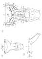
図1(a)(b)及び図2(a)(b)に示すホルダ1はプラスチックにより成形され、このホルダ1の頭部2内には、図2(c)に示すように、金属からなる左右両支持アーム3と、プラスチックからなる二股状のプッシャ4と、プラスチックからなる操作摘み5と、金属からなる圧縮コイルばね6とが組み込まれている。この頭部2の前端部の左右両側には開口7が形成されている。前記左右両支持アーム3は、基端部で頭部2の支軸8を中心に左右方向Yへ回動可能に支持され、その基端部から頭部2の前側へ延設されて頭部2の左右両開口7から頭部2の外側へ突出する外腕部9(先端部)を有している。前記プッシャ4は、頭部2の前端部付近で左右両支持アーム3間に配置され、基端部で頭部2に対し前後方向Xへ移動可能に支持され、その基端部から左右両支持アーム3側へ延設された内腕部10と、その左右両内腕部10から前方へ延びて頭部2の左右両開口7から頭部2の外側へ突出する外腕部11(先端部)とを有している。前記操作摘み5は、頭部2の後部で前後方向Xへ移動可能に支持され、頭部2の後端部から頭部2の外側へ突出している。前記圧縮コイルばね6(弾性体)は、このプッシャ4の基端部と操作摘み5との間に介在され、プッシャ4の基端部を前方へ付勢して頭部2の前端部に圧接させた状態で操作摘み5を後方へ付勢して頭部2の外側へ突出させた非操作状態にするとともに、左右両支持アーム3を操作摘み5を介して付勢して最開状態にする。この左右両支持アーム3の基端部には当接部12が形成され、この操作摘み5の左右両側にはこの当接部12に面する押接部13が形成されている。この操作摘み5を圧縮コイルばね6の弾性力に抗して前方へ押すと、操作摘み5の左右両押接部13が左右両支持アーム3の当接部12を押して左右両支持アーム3の外腕部9が最開状態から互いに閉じる。この操作摘み5から手を離すと、操作摘み5が前記非操作状態に戻るとともに、左右両支持アーム3の外腕部9が最開状態に戻る。Hereinafter, a swing-type razor according to an embodiment of the present invention will be described with reference to the drawings.
The
前記左右両支持アーム3の外腕部9においてそれぞれ鉤状端部14が形成されている。前記プッシャ4の左右両外腕部11においてそれぞれ圧接端部15が形成されている。この左右両支持アーム3の外腕部9とプッシャ4の左右両外腕部11とはホルダ1の頭部2の左右両開口7及びその頭部2の前端部の外側において上下方向Zで互いに隣接して並んでいる。 A flange-shaped
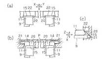
図1(a)(b)並びに図3(a)(b)(c)及び図5(a)(b)に示す剃刀ヘッド16においては、組付部材としての刃台17と天板18との間で複数(4枚)の刃体19が挟着され、この天板18の左右両側から突出する腕部18a間で各刃体19の刃先19aが表側に露出し、この刃台17に形成されたガード17aに刃体19の刃先19aが面している。このガード17aの表面側にはシェービングエイドがインサート射出成形により一体に設けられている。この剃刀ヘッド16の裏側にある刃台17で左右方向Y(刃先19aの延設方向)の両側に形成された凹部20においては、図7(a)(b)(c)に示すように、支持孔21(支持部)と圧接部22とが互いに隣接して並ぶように形成されている。この剃刀ヘッド16の左右方向Yの両端部においては、刃台17と天板18とにそれぞれ壁23,24が突設されてそれらの壁23,24間にばね室25が形成されているとともに、これらの壁23,24よりもガード17a側で刃台17に支軸26が形成され、この左右両支軸26を結ぶ回動中心線26aは左右方向Y(刃先19aの延設方向)に沿う。 In the
図1(a)(b)並びに図4(a)(b)(c)及び図5(a)(b)に示すシェービングエイド部材27においては、プラスチックからなる台部材29の表側に形成された凹所28aにシェービングエイド28が嵌め込まれて載せられている。この台部材29においては、左右方向Yの両側に両腕部30が形成され、この左右両腕部30の相対向面側で、左右両腕部30の先端部に支持孔32が形成されているとともに、この支持孔32の付近から片持ち梁状の板ばね31が一体に湾曲形成されてシェービングエイド28側へ延設されている。この板ばね31を直線的に延設させてもよい。左右両腕部30にある板ばね31のうち一方のものを省略してもよい。この台部材29の左右方向Yの寸法は約50mmである。このシェービングエイド28の左右方向Yの寸法は約38mmである。このシェービングエイド28の表面で左右方向Yに対し直交する方向における幅は、左右方向Yの中央部で最も広くなっており、約8mmである。このシェービングエイド28はこの台部材29の表面から高さ約5mmだけ突出している。このシェービングエイド28とは、例えば、石鹸やシェービングクリームや潤滑性助長剤やひげ軟化剤や乳液や薬剤や発毛抑制剤や脱毛剤やアフターローションや保湿剤や止血剤などの単独物ばかりでなく、これらの単独物を互いに組み合わせた複合物や、この単独物または複合物をスポンジなどの多孔質体に含ませた含有物である。 The shaving
図5(a)(b)に示すように、前記シェービングエイド部材27において台部材29とそれに載置されたシェービングエイド28とは、剃刀ヘッド16に対しガード17aに対する反対側でその剃刀ヘッド16の外側に並ぶように配設され、この台部材29の左右両腕部30が剃刀ヘッド16の左右方向Yの両端部の外側に当てがわれて左右両腕部30とそれらの間の剃刀ヘッド16とが互いに左右方向Yへ並ぶ。その際、この左右両腕部30の支持孔32に剃刀ヘッド16の左右両支軸26が回動中心部として挿入されるとともに、この左右両腕部30の板ばね31が剃刀ヘッド16の左右両ばね室25に挿入される。そのため、シェービングエイド部材27は剃刀ヘッド16に対しその表側と裏側とを結ぶ方向で揺動するように左右両支軸26の回動中心線26aを中心に回動可能に支持される。As shown in FIGS. 5 (a) and 5 (b), in the
前記左右両支持アーム3を互いに閉じた状態でそれらの外腕部9を前記刃台17の左右両凹部20に挿入した後、左右両支持アーム3を最開状態にすると、図6(a)に示すように、剃刀ヘッド16がホルダ1の頭部2に対し首振り可能に支持された取付状態となる。この取付状態では、図7(a)(b)(c)に示すように、この左右両外腕部9の鉤状端部14が左右両凹部20の支持孔21に挿入されて支持されるとともに、前記プッシャ4の左右両外腕部11の圧接端部15が左右両凹部20の圧接部22に圧接され、この左右両鉤状端部14を互いに結ぶ回動中心線Pを中心に剃刀ヘッド16がシェービングエイド部材27とともに首振り方向Qへ揺動し得る。図3(a)(b)(c)、図5(a)(b)及び図6(a)に示すように、剃刀ヘッド16に対するシェービングエイド部材27の回動中心線26aは、天板18よりもガード17a側でこの回動中心線Pよりもガード17a側に位置し、刃台17のガード17a上と天板18上とを結ぶ皮膚接触面Hよりも裏側で且つそのガード17aよりも天板18側に位置し、そのガード17aに最も近い刃体19の刃先19aが延びる左右方向Yの延長線上またはその延長線付近に位置している。 When the left and
図6(a)に示すように、台部材29の左右両腕部30の板ばね31がばね室25で刃台17の壁23に支えられた状態で、シェービングエイド部材27は、その板ばね31により剃刀ヘッド16の裏側から表側へすなわち回動方向Rの両側向きRF,RBのうち一方の向きRFへ付勢され、左右両腕部30が天板18の壁24に並んだところで停止する初期位置Aとなる。その初期位置Aでは、シェービングエイド28が前記皮膚接触面Hから表側へ突出する。図6(b)に示すように、使用時、このシェービングエイド部材27は、その初期位置Aから板ばね31の弾性力に抗して剃刀ヘッド16の表側から裏側へすなわち回動方向Rの両側向きRF,RBのうち他方の向きRBへ回動し、左右両腕部30が刃台17の壁23に当接したところで停止する所定回動範囲内で、剃刀ヘッド16に対し揺動し得る。その所定回動範囲におけるシェービングエイド部材27の振り角については、0〜45°好ましくは0〜30°に設定されている。使用時にシェービングエイド28が減って台部材29の表面からの高さが低くなった場合には、図6(c)に示すように、そのシェービングエイド28の表面が皮膚面に当てがわれる。使用時にシェービングエイド28が台部材29の表面付近まで減った場合、例えば、シェービングエイド28の表面の一部が台部材29の表面に達した場合、剃刀ヘッド16及びシェービングエイド部材27の交換の目安にすることができる。 As shown in FIG. 6A, in the state where the
剃刀ヘッド16を圧接するプッシャ4に対する圧縮コイルばね6の弾性力や、シェービングエイド部材27に対する板ばね31の弾性力は、種々設定することができる。例えば、圧縮コイルばね6の弾性力は板ばね31の弾性力よりも大きく設定されている。そのため、剃刀ヘッド16及びシェービングエイド部材27を皮膚面に当てがうと、シェービングエイド部材27が剃刀ヘッド16に対し前記初期位置Aから回動し始めた後に剃刀ヘッド16と一体的に回動し、剃刀ヘッド16がシェービングエイド部材27とともに首振り方向Qへ揺動する。 The elastic force of the compression coil spring 6 with respect to the
また、前記左右両支持アーム3を互いに閉じた状態でそれらの外腕部9を前記刃台17の左右両凹部20から抜くと、剃刀ヘッド16をホルダ1の頭部2から取り外すことができる。ちなみに、前記左右両支持アーム3については、操作摘み5を押してもすぐには閉動せず、操作摘み5が不用意に押されて剃刀ヘッド16がホルダ1の頭部2から取り外されることを防止するため、操作摘み5をある程度押すと閉じるようになっている。 Further, when the
前記実施形態以外に下記のように構成してもよい。
* シェービングエイド部材27における台部材29と剃刀ヘッド16の刃台17または天板18とを一体成形して連繋部で互いにつなぎ、その連繋部を剃刀ヘッド16に対するシェービングエイド部材27の回動中心部とする。You may comprise as follows other than the said embodiment.
* The
* ホルダ1の頭部2に対し剃刀ヘッド16を一体に設けたり着脱可能に支持した剃刀において、その剃刀ヘッド16にシェービングエイド部材27を回動可能に支持する。
* 前述した実施形態では、シェービングエイド部材27を剃刀ヘッド16に対しガード17aに対する反対側で並ぶように配設したが、シェービングエイド部材を剃刀ヘッド16に対しガード17a側で並ぶように配設したり左右方向Yの両側で並ぶように配設する。* In the razor in which the
* In the above-described embodiment, the shaving
*シェービングエイド部材27を剃刀ヘッド16に対し着脱可能にして交換できるようにする。* The shaving
* 剃刀ヘッド16の左右両側で刃台17または天板18に対し板ばね31を一体に形成してその板ばね31によりシェービングエイド部材27を付勢したり、シェービングエイド部材27の台部材29または剃刀ヘッド16の刃台17や天板18に対し左右方向Yの中央部で一つの板ばね31を一体に形成してその板ばね31によりシェービングエイド部材27を付勢する。 * A
* シェービングエイド28については固形状でも液状でも半液状でもよい。固形状の場合にはそのままシェービングエイド28を台部材29に取着する。液状や半液状の場合には軟質または硬質の多孔質体、例えばスポンジや軽石や繊維構造である四フッ化エチレン樹脂などの多孔質体にシェービングエイド28を含浸させたものを台部材29に取着する。これらの多孔質体については形状の維持できるものが好ましい。この多孔質体の孔径については、種々設定できるが、0.01〜50μmが好ましい。 * The shaving
* 台部材29に対しシェービングエイド28をインサート射出成形により一体に設けたり、固形状のシェービングエイド28や上記の多孔質体を台部材29と分離して設けた後にそれらを台部材29に取着する。 * Shaving
* シェービングエイド部材27において台部材29に対し回転可能に支持したローラの外周にシェービングエイド28を設ける。
* 剃刀ヘッド16及びシェービングエイド部材27にキャップを被せて刃体19及びシェービングエイド28を保護する。* A shaving
* Cap the
* 前記実施形態の首振り式剃刀は主に手足の体毛剃りに使用するが、髭剃りに使用することもできる。
次に、請求項以外の技術的思想を述べる。* The swing-type razor of the above embodiment is mainly used for shaving limbs, but can also be used for shaving.
Next, technical ideas other than the claims will be described.
16…剃刀ヘッド、17…刃台(組付部材)、17a…ガード、18…天板(組付部材)、19…刃体、19a…刃先、26…支軸(回動中心部)、26a…回動中心線、27…シェービングエイド部材、28…シェービングエイド、29…台部材、30…腕部、31…板ばね(弾性体)、32…支持孔(回動中心部)、A…シェービングエイド部材の初期位置、H…剃刀ヘッドの皮膚接触面、Y…左右方向(刃先の延設方向)R…シェービングエイド部材の移動方向、RF,RB…向き。 16 ... Razor head, 17 ... Blade base (assembly member), 17a ... Guard, 18 ... Top plate (assembly member), 19 ... Blade body, 19a ... Cutting edge, 26 ... Support shaft (rotation center), 26a Rotating center line, 27 Shaving aid member, 28 Shaving aid, 29 Stand member, 30 Arm, 31 Leaf spring (elastic body), 32 Support hole (rotating center), A Shaving Initial position of aid member, H: Skin contact surface of razor head, Y: Left-right direction (extension direction of blade edge) R: Movement direction of shaving aid member, RF, RB: Direction.
Claims (3)
Translated fromJapaneseこのシェービングエイド部材の台部材は、剃刀ヘッドに対し刃体の刃先の延設方向の両側でその剃刀ヘッドの両端部の外側に並ぶように配設された腕部を有し、この両腕部間に配設された剃刀ヘッドに対し両腕部で回動中心部により支持され、このシェービングエイド部材の台部材及びシェービングエイドは剃刀ヘッドの組付部材に対しガードに対する反対側でその剃刀ヘッドの外側に並ぶように配設され、
このシェービングエイド部材は、回動方向の両側向きのうち一方の向きへ弾性体により付勢されて停止する初期位置から他方の向きへ、刃体の刃先の延設方向に沿う回動中心部の回動中心線を中心に弾性体の弾性力に抗して剃刀ヘッドに対し所定回動範囲内で揺動可能に支持されている
ことを特徴とする剃刀。A razor head provided with a guard facing the blade edge of the blade body on the assembly member provided with the blade body, and a shaving aid member having a base member on which the shaving aid is placed,
The base member of this shaving aid member has arm portions arranged so as to be arranged outside both end portions of the razor head on both sides in the extending direction of the blade edge of the blade body with respect to the razor head. The razor head disposed between them is supported by the center of rotation at both arms, and the base member of the shaving aid member and the shaving aid are opposite to the guard with respect to the assembly member of the razor head. Arranged to line up outside,
This shaving aid member has a rotation center portion along the extending direction of the blade edge of the blade body from the initial position where the elastic body is biased and stopped by one of the rotation directions on both sides. A razor characterizedby being supported so as to be able to swing within a predetermined rotation range with respect to a razor head against the elastic force of an elastic body around a rotation center line .
Priority Applications (4)
| Application Number | Priority Date | Filing Date | Title |
|---|---|---|---|
| JP2005262484AJP4921747B2 (en) | 2005-09-09 | 2005-09-09 | razor |
| EP06821794.2AEP1935588B2 (en) | 2005-09-09 | 2006-08-29 | Razor |
| US11/991,269US7877879B2 (en) | 2005-09-09 | 2006-08-29 | Razor |
| PCT/JP2006/316915WO2007029553A1 (en) | 2005-09-09 | 2006-08-29 | Razor |
Applications Claiming Priority (1)
| Application Number | Priority Date | Filing Date | Title |
|---|---|---|---|
| JP2005262484AJP4921747B2 (en) | 2005-09-09 | 2005-09-09 | razor |
Publications (2)
| Publication Number | Publication Date |
|---|---|
| JP2007068923A JP2007068923A (en) | 2007-03-22 |
| JP4921747B2true JP4921747B2 (en) | 2012-04-25 |
Family
ID=37835674
Family Applications (1)
| Application Number | Title | Priority Date | Filing Date |
|---|---|---|---|
| JP2005262484AExpired - Fee RelatedJP4921747B2 (en) | 2005-09-09 | 2005-09-09 | razor |
Country Status (4)
| Country | Link |
|---|---|
| US (1) | US7877879B2 (en) |
| EP (1) | EP1935588B2 (en) |
| JP (1) | JP4921747B2 (en) |
| WO (1) | WO2007029553A1 (en) |
Cited By (2)
| Publication number | Priority date | Publication date | Assignee | Title |
|---|---|---|---|---|
| WO2014073502A1 (en) | 2012-11-06 | 2014-05-15 | 株式会社 貝印刃物開発センター | Razor with attached shaving aid |
| US10252432B2 (en) | 2014-07-31 | 2019-04-09 | Kai R&D Center Co., Ltd. | Razor having attached shaving aid |
Families Citing this family (63)
| Publication number | Priority date | Publication date | Assignee | Title |
|---|---|---|---|---|
| US7811553B2 (en)* | 2005-11-09 | 2010-10-12 | The Gillette Company | Molded shaving aid compositions, components and methods of manufacture |
| JP4950507B2 (en)* | 2006-02-14 | 2012-06-13 | 株式会社貝印刃物開発センター | razor |
| JP4950506B2 (en)* | 2006-02-14 | 2012-06-13 | 株式会社貝印刃物開発センター | razor |
| JP4977374B2 (en)* | 2006-02-14 | 2012-07-18 | 株式会社貝印刃物開発センター | razor |
| KR100749925B1 (en) | 2006-06-29 | 2007-08-16 | 주식회사 도루코 | Shaver |
| JP5010896B2 (en)* | 2006-10-31 | 2012-08-29 | 株式会社貝印刃物開発センター | razor |
| EP2117785B1 (en)* | 2007-03-02 | 2011-08-03 | The Gillette Company | Razor having a wing shaped contouring shaving aid |
| MX2010011663A (en)* | 2008-04-24 | 2011-01-21 | Abbott Gmbh & Co Kg | 1- (7-(hexahydropyrrolo [3, 4-c] pyrrol-2 (1h) -yl) quin0lin-4-yl) -3- (pyrazin-2-yl) urea derivatives and related compounds as glycogen synthase kinase 3 (gsk-3). |
| US8307553B2 (en) | 2008-05-01 | 2012-11-13 | Eveready Battery Company, Inc. | Razor cartridge |
| CN102119073B (en)* | 2008-05-01 | 2013-12-11 | 永备电池有限公司 | Separable lubrication |
| US20100313426A1 (en)* | 2009-06-12 | 2010-12-16 | Terence Gordon Royle | Safety razor with pivot and rotation |
| US8474144B2 (en)* | 2009-08-12 | 2013-07-02 | The Gillette Company | Safety razor with rotational movement and locking button |
| USD622904S1 (en)* | 2009-12-02 | 2010-08-31 | The Gillette Company | Razor cartridge lubrication ring |
| US8407900B2 (en)* | 2010-04-12 | 2013-04-02 | The Gillette Company | Shaving cartridge having mostly elastomeric wings |
| US8745883B2 (en) | 2010-09-29 | 2014-06-10 | The Gillette Company | Razor handle with a rotatable portion |
| US8745882B2 (en) | 2010-09-29 | 2014-06-10 | The Gillette Company | Flexible and separable portion of a razor handle |
| US20120192428A1 (en)* | 2011-01-31 | 2012-08-02 | Rovcal, Inc. | Electric Shaver With Moisturizing Bar |
| PL2508309T3 (en) | 2011-04-05 | 2017-02-28 | The Gillette Company | Razor handle with a rotatable portion |
| EP2591895B1 (en)* | 2011-11-10 | 2019-02-27 | The Gillette Company LLC | Razor cartridge with lubrication and moisturizing strips |
| US20130160307A1 (en)* | 2011-12-22 | 2013-06-27 | Daren Mark Howell | Razor cartridge that rotates about a virtual pivot axis |
| US8938885B2 (en) | 2012-05-01 | 2015-01-27 | The Gillette Company | Razor handle with a rotatable portion |
| US9283685B2 (en) | 2012-07-26 | 2016-03-15 | Shavelogic, Inc. | Pivoting razors |
| US9486930B2 (en) | 2012-09-27 | 2016-11-08 | Shavelogic, Inc. | Shaving systems |
| WO2014051842A1 (en) | 2012-09-27 | 2014-04-03 | Shavelogic, Inc. | Shaving systems |
| WO2014051843A1 (en) | 2012-09-28 | 2014-04-03 | Shavelogic, Inc. | Shaving systems |
| JP6093551B2 (en)* | 2012-11-06 | 2017-03-08 | 株式会社貝印刃物開発センター | razor |
| US9623575B2 (en) | 2012-12-18 | 2017-04-18 | Shavelogic, Inc. | Shaving systems |
| MX361580B (en)* | 2012-12-21 | 2018-12-11 | Bic Violex Sa | Shaver. |
| MX361581B (en)* | 2012-12-21 | 2018-12-11 | Bic Violex Sa | Shaver. |
| EP2934826B1 (en)* | 2012-12-21 | 2017-12-13 | BIC-Violex S.A. | Shaver |
| AU2014226262A1 (en) | 2013-03-04 | 2015-09-17 | The Gillette Company | Razor with two glide members pivoting about a single axis |
| MX2015011594A (en) | 2013-03-04 | 2015-12-09 | Gillette Co | Article for carrying a glide member for use with a razor. |
| WO2014137775A1 (en) | 2013-03-04 | 2014-09-12 | The Gillette Company | Article for carrying a glide member for use with a razor |
| BR112015030319B1 (en) | 2013-06-04 | 2021-03-09 | Bic-Violex Sa | adapter for a shaving or waxing cartridge, shaving or waxing kit, razor and shaving or waxing method |
| BR112015031466A2 (en) | 2013-06-17 | 2017-07-25 | Gillette Co | sliding element comprising little to non-hygroscopic components for use with shavers or shavers |
| US20150158192A1 (en) | 2013-12-09 | 2015-06-11 | Shavelogic, Inc. | Multi-material pivot return for shaving systems |
| US10562199B2 (en)* | 2014-01-15 | 2020-02-18 | The Gillette Company Llc | Connecting member |
| WO2015142663A1 (en) | 2014-03-21 | 2015-09-24 | Shavelogic, Inc. | Metal spring return |
| EP2979829B1 (en)* | 2014-07-31 | 2018-09-19 | Beiersdorf Aktiengesellschaft | Safety razor and blade unit for safety razor |
| US20160318198A1 (en)* | 2015-04-30 | 2016-11-03 | Larry Brazley | Razor Attachment |
| CN108367448B (en)* | 2015-12-17 | 2021-01-22 | 比克沃莱克斯公司 | razor head |
| CA3018095A1 (en) | 2016-03-18 | 2017-09-21 | Personal Care Marketing And Research, Inc. | Razor cartridge |
| US9993931B1 (en)* | 2016-11-23 | 2018-06-12 | Personal Care Marketing And Research, Inc. | Razor docking and pivot |
| US10773408B2 (en) | 2018-03-30 | 2020-09-15 | The Gillette Company Llc | Shaving razor cartridge |
| BR112020020132A2 (en) | 2018-03-30 | 2021-01-05 | The Gillette Company Llc | HANDLE OF SHAVING OR DEVILING APPLIANCE WITH MOBILE LIMBS |
| EP3774215B1 (en) | 2018-03-30 | 2024-03-13 | The Gillette Company LLC | Razor handle with a pivoting portion |
| EP3774221A1 (en)* | 2018-03-30 | 2021-02-17 | The Gillette Company LLC | Razor handle with a pivoting portion |
| WO2019191163A1 (en) | 2018-03-30 | 2019-10-03 | The Gillette Company Llc | Razor handle with a pivoting portion |
| US11607820B2 (en) | 2018-03-30 | 2023-03-21 | The Gillette Company Llc | Razor handle with movable members |
| CN111801205B (en) | 2018-03-30 | 2022-08-23 | 吉列有限责任公司 | Razor handle with pivoting portion |
| USD874061S1 (en) | 2018-03-30 | 2020-01-28 | The Gillette Company Llc | Shaving razor cartridge |
| EP3774227A1 (en) | 2018-03-30 | 2021-02-17 | The Gillette Company LLC | Razor handle with movable members |
| EP3546156B1 (en) | 2018-03-30 | 2021-03-10 | The Gillette Company LLC | Razor handle with a pivoting portion |
| CN111819048A (en) | 2018-03-30 | 2020-10-23 | 吉列有限责任公司 | Razor handle with pivoting portion |
| WO2019190962A1 (en) | 2018-03-30 | 2019-10-03 | The Gillette Company Llc | Razor handle with a pivoting portion |
| CA3092879A1 (en) | 2018-03-30 | 2019-10-03 | The Gillette Company Llc | Razor handle with movable members |
| JP2021515672A (en) | 2018-03-30 | 2021-06-24 | ザ ジレット カンパニー リミテッド ライアビリティ カンパニーThe Gillette Company Llc | Razor system for shaving |
| JP7104168B2 (en) | 2018-03-30 | 2022-07-20 | ザ ジレット カンパニー リミテッド ライアビリティ カンパニー | Razor handle with pivot part |
| WO2020016348A1 (en) | 2018-07-18 | 2020-01-23 | Bic Violex S.A. | Shaving blade assemblies |
| USD884970S1 (en) | 2019-02-27 | 2020-05-19 | PCMR International Ltd. | Razor cartridge guard |
| USD884971S1 (en) | 2019-02-27 | 2020-05-19 | Pcmr International Ltd | Razor cartridge |
| USD884969S1 (en) | 2019-02-27 | 2020-05-19 | Pcmr International Ltd | Combined razor cartridge guard and docking |
| US11000960B1 (en) | 2020-11-16 | 2021-05-11 | Personal Care Marketing And Research, Inc. | Razor exposure |
Family Cites Families (26)
| Publication number | Priority date | Publication date | Assignee | Title |
|---|---|---|---|---|
| DE334947C (en)* | 1921-03-26 | Robert Rohde | Roller razor for single-edged razor blades with soap foam separator | |
| US2677883A (en)* | 1949-02-08 | 1954-05-11 | Schallgruber Fredrick | Lather applying razor |
| US4074429A (en)* | 1976-08-23 | 1978-02-21 | Roberts Thomas G | Novel lathering device and razor assembly |
| JPS58149163U (en) | 1982-03-31 | 1983-10-06 | ア−ス製薬株式会社 | Convenient razor |
| US4774765A (en)* | 1986-09-02 | 1988-10-04 | Warner-Lambert Company | Blade assembly featuring variable span |
| US4709477A (en)* | 1986-09-02 | 1987-12-01 | Warner-Lambert Company | Blade assembly featuring variable span |
| US4944090A (en)* | 1989-04-03 | 1990-07-31 | Stanley Sumnall | Razor head with yieldable shaving aid |
| DE8911246U1 (en) | 1989-09-21 | 1991-01-24 | Wilkinson Sword GmbH, 5650 Solingen | Shaver head, especially razor blade unit |
| US5056222A (en) | 1990-09-28 | 1991-10-15 | The Gillette Company | Shaving system |
| DE4308243A1 (en)* | 1993-03-11 | 1994-09-15 | Juergens Masch Gmbh & Co | Projectile wide weaving machine |
| JPH0748224Y2 (en) | 1993-06-17 | 1995-11-08 | 株式会社貝印刃物開発センター | Safety razor |
| JP2892258B2 (en) | 1993-07-29 | 1999-05-17 | 日本碍子株式会社 | Ceramic honeycomb structure |
| US6295734B1 (en)* | 1995-03-23 | 2001-10-02 | The Gillette Company | Safety razors |
| GB9505917D0 (en) | 1995-03-23 | 1995-05-10 | Gillette Co | Safety razors |
| US6161287A (en)† | 1998-04-24 | 2000-12-19 | The Gillette Company | Razor blade system |
| US6145201A (en)* | 1999-07-27 | 2000-11-14 | Andrews; Edward A. | Underarm shaving devices |
| JP3335594B2 (en) | 1999-07-27 | 2002-10-21 | 株式会社貝印刃物開発センター | Safety razor |
| KR100669144B1 (en) | 1999-11-29 | 2007-01-15 | 코닌클리케 필립스 일렉트로닉스 엔.브이. | Shaver with shaving head with sub-frame and main frame |
| US6584690B2 (en)* | 2000-02-16 | 2003-07-01 | Warner-Lambert Company | Wet shaving assembly |
| EP1252985B1 (en)* | 2001-04-27 | 2005-10-19 | Eveready Battery Company, Inc. | Wet shaving device with guard/transfer roller and replaceable shaving aid |
| US7266895B2 (en)* | 2002-04-24 | 2007-09-11 | Eveready Battery Company, Inc. | Razor assembly |
| US7367125B2 (en)* | 2003-12-10 | 2008-05-06 | The Gillette Company | Shaving systems |
| US20060080837A1 (en)* | 2004-10-20 | 2006-04-20 | Robert Johnson | Shaving razors and cartridges |
| JP4874553B2 (en)* | 2005-01-31 | 2012-02-15 | 株式会社貝印刃物開発センター | Safety razor for shaving the hair of legs and arms as well as the face |
| JP5010896B2 (en)* | 2006-10-31 | 2012-08-29 | 株式会社貝印刃物開発センター | razor |
| EP2117785B1 (en)* | 2007-03-02 | 2011-08-03 | The Gillette Company | Razor having a wing shaped contouring shaving aid |
- 2005
- 2005-09-09JPJP2005262484Apatent/JP4921747B2/ennot_activeExpired - Fee Related
- 2006
- 2006-08-29EPEP06821794.2Apatent/EP1935588B2/ennot_activeNot-in-force
- 2006-08-29WOPCT/JP2006/316915patent/WO2007029553A1/enactiveApplication Filing
- 2006-08-29USUS11/991,269patent/US7877879B2/enactiveActive
Cited By (3)
| Publication number | Priority date | Publication date | Assignee | Title |
|---|---|---|---|---|
| WO2014073502A1 (en) | 2012-11-06 | 2014-05-15 | 株式会社 貝印刃物開発センター | Razor with attached shaving aid |
| US9889570B2 (en) | 2012-11-06 | 2018-02-13 | Kai R&D Center Co., Ltd. | Razor with attached shaving aid |
| US10252432B2 (en) | 2014-07-31 | 2019-04-09 | Kai R&D Center Co., Ltd. | Razor having attached shaving aid |
Also Published As
| Publication number | Publication date |
|---|---|
| US7877879B2 (en) | 2011-02-01 |
| EP1935588A1 (en) | 2008-06-25 |
| JP2007068923A (en) | 2007-03-22 |
| WO2007029553A1 (en) | 2007-03-15 |
| EP1935588A4 (en) | 2009-11-11 |
| US20080250646A1 (en) | 2008-10-16 |
| EP1935588B1 (en) | 2012-03-07 |
| EP1935588B2 (en) | 2015-02-25 |
Similar Documents
| Publication | Publication Date | Title |
|---|---|---|
| JP4921747B2 (en) | razor | |
| JP5010896B2 (en) | razor | |
| JP5297189B2 (en) | Razor cartridge with guard bar to be separated | |
| RU2465125C2 (en) | Safety razor with pivoting blade unit | |
| KR102009179B1 (en) | Shaver with interchangeable cartridge, cartridge and head and handle assembly for such shaver | |
| US7971363B2 (en) | Oscillating razor | |
| JP4975042B2 (en) | Shaving cartridge pivot | |
| KR20200018390A (en) | Head converter | |
| JP2009539473A (en) | Laser handle | |
| JP2013523390A (en) | Shaving cartridge with biasing member | |
| EP2176042B1 (en) | Shaving implement | |
| US7658009B2 (en) | Shaving implement | |
| WO2019022043A1 (en) | Oscillating razor | |
| JP5433320B2 (en) | T type safety razor | |
| JP2001079281A (en) | Safety razor | |
| JP4377606B2 (en) | Nail clippers | |
| JPH06154437A (en) | Safety razor | |
| CN114536413B (en) | High-freedom-degree universal shaver and shaving unit floating mechanism thereof | |
| JP3174546B2 (en) | Swing razor | |
| JP4698954B2 (en) | Blade body mounting part in replaceable blade type razor | |
| JPH0118144Y2 (en) | ||
| JPH0576662A (en) | Safety razor | |
| JPH0467844B2 (en) |
Legal Events
| Date | Code | Title | Description |
|---|---|---|---|
| A621 | Written request for application examination | Free format text:JAPANESE INTERMEDIATE CODE: A621 Effective date:20080903 | |
| A131 | Notification of reasons for refusal | Free format text:JAPANESE INTERMEDIATE CODE: A131 Effective date:20110719 | |
| A521 | Written amendment | Free format text:JAPANESE INTERMEDIATE CODE: A523 Effective date:20110826 | |
| TRDD | Decision of grant or rejection written | ||
| A01 | Written decision to grant a patent or to grant a registration (utility model) | Free format text:JAPANESE INTERMEDIATE CODE: A01 Effective date:20120131 | |
| A01 | Written decision to grant a patent or to grant a registration (utility model) | Free format text:JAPANESE INTERMEDIATE CODE: A01 | |
| A61 | First payment of annual fees (during grant procedure) | Free format text:JAPANESE INTERMEDIATE CODE: A61 Effective date:20120203 | |
| R150 | Certificate of patent or registration of utility model | Ref document number:4921747 Country of ref document:JP Free format text:JAPANESE INTERMEDIATE CODE: R150 Free format text:JAPANESE INTERMEDIATE CODE: R150 | |
| FPAY | Renewal fee payment (event date is renewal date of database) | Free format text:PAYMENT UNTIL: 20150210 Year of fee payment:3 | |
| R250 | Receipt of annual fees | Free format text:JAPANESE INTERMEDIATE CODE: R250 | |
| R250 | Receipt of annual fees | Free format text:JAPANESE INTERMEDIATE CODE: R250 | |
| LAPS | Cancellation because of no payment of annual fees |