JP4921550B2 - How to give emotional features to computer-generated avatars during gameplay - Google Patents
How to give emotional features to computer-generated avatars during gameplayDownload PDFInfo
- Publication number
- JP4921550B2 JP4921550B2JP2009509822AJP2009509822AJP4921550B2JP 4921550 B2JP4921550 B2JP 4921550B2JP 2009509822 AJP2009509822 AJP 2009509822AJP 2009509822 AJP2009509822 AJP 2009509822AJP 4921550 B2JP4921550 B2JP 4921550B2
- Authority
- JP
- Japan
- Prior art keywords
- user
- avatar
- response
- game play
- computer
- Prior art date
- Legal status (The legal status is an assumption and is not a legal conclusion. Google has not performed a legal analysis and makes no representation as to the accuracy of the status listed.)
- Active
Links
Images


Classifications
- G—PHYSICS
- G06—COMPUTING OR CALCULATING; COUNTING
- G06F—ELECTRIC DIGITAL DATA PROCESSING
- G06F3/00—Input arrangements for transferring data to be processed into a form capable of being handled by the computer; Output arrangements for transferring data from processing unit to output unit, e.g. interface arrangements
- G06F3/01—Input arrangements or combined input and output arrangements for interaction between user and computer
- G06F3/011—Arrangements for interaction with the human body, e.g. for user immersion in virtual reality
- A—HUMAN NECESSITIES
- A63—SPORTS; GAMES; AMUSEMENTS
- A63F—CARD, BOARD, OR ROULETTE GAMES; INDOOR GAMES USING SMALL MOVING PLAYING BODIES; VIDEO GAMES; GAMES NOT OTHERWISE PROVIDED FOR
- A63F13/00—Video games, i.e. games using an electronically generated display having two or more dimensions
- A63F13/20—Input arrangements for video game devices
- A63F13/21—Input arrangements for video game devices characterised by their sensors, purposes or types
- A63F13/213—Input arrangements for video game devices characterised by their sensors, purposes or types comprising photodetecting means, e.g. cameras, photodiodes or infrared cells
- A—HUMAN NECESSITIES
- A63—SPORTS; GAMES; AMUSEMENTS
- A63F—CARD, BOARD, OR ROULETTE GAMES; INDOOR GAMES USING SMALL MOVING PLAYING BODIES; VIDEO GAMES; GAMES NOT OTHERWISE PROVIDED FOR
- A63F13/00—Video games, i.e. games using an electronically generated display having two or more dimensions
- A63F13/20—Input arrangements for video game devices
- A63F13/21—Input arrangements for video game devices characterised by their sensors, purposes or types
- A63F13/215—Input arrangements for video game devices characterised by their sensors, purposes or types comprising means for detecting acoustic signals, e.g. using a microphone
- A—HUMAN NECESSITIES
- A63—SPORTS; GAMES; AMUSEMENTS
- A63F—CARD, BOARD, OR ROULETTE GAMES; INDOOR GAMES USING SMALL MOVING PLAYING BODIES; VIDEO GAMES; GAMES NOT OTHERWISE PROVIDED FOR
- A63F13/00—Video games, i.e. games using an electronically generated display having two or more dimensions
- A63F13/40—Processing input control signals of video game devices, e.g. signals generated by the player or derived from the environment
- A63F13/42—Processing input control signals of video game devices, e.g. signals generated by the player or derived from the environment by mapping the input signals into game commands, e.g. mapping the displacement of a stylus on a touch screen to the steering angle of a virtual vehicle
- A—HUMAN NECESSITIES
- A63—SPORTS; GAMES; AMUSEMENTS
- A63F—CARD, BOARD, OR ROULETTE GAMES; INDOOR GAMES USING SMALL MOVING PLAYING BODIES; VIDEO GAMES; GAMES NOT OTHERWISE PROVIDED FOR
- A63F13/00—Video games, i.e. games using an electronically generated display having two or more dimensions
- A63F13/55—Controlling game characters or game objects based on the game progress
- A63F13/58—Controlling game characters or game objects based on the game progress by computing conditions of game characters, e.g. stamina, strength, motivation or energy level
- A—HUMAN NECESSITIES
- A63—SPORTS; GAMES; AMUSEMENTS
- A63F—CARD, BOARD, OR ROULETTE GAMES; INDOOR GAMES USING SMALL MOVING PLAYING BODIES; VIDEO GAMES; GAMES NOT OTHERWISE PROVIDED FOR
- A63F13/00—Video games, i.e. games using an electronically generated display having two or more dimensions
- A63F13/60—Generating or modifying game content before or while executing the game program, e.g. authoring tools specially adapted for game development or game-integrated level editor
- A63F13/65—Generating or modifying game content before or while executing the game program, e.g. authoring tools specially adapted for game development or game-integrated level editor automatically by game devices or servers from real world data, e.g. measurement in live racing competition
- A—HUMAN NECESSITIES
- A63—SPORTS; GAMES; AMUSEMENTS
- A63F—CARD, BOARD, OR ROULETTE GAMES; INDOOR GAMES USING SMALL MOVING PLAYING BODIES; VIDEO GAMES; GAMES NOT OTHERWISE PROVIDED FOR
- A63F13/00—Video games, i.e. games using an electronically generated display having two or more dimensions
- A63F13/70—Game security or game management aspects
- A63F13/79—Game security or game management aspects involving player-related data, e.g. identities, accounts, preferences or play histories
- A—HUMAN NECESSITIES
- A63—SPORTS; GAMES; AMUSEMENTS
- A63F—CARD, BOARD, OR ROULETTE GAMES; INDOOR GAMES USING SMALL MOVING PLAYING BODIES; VIDEO GAMES; GAMES NOT OTHERWISE PROVIDED FOR
- A63F13/00—Video games, i.e. games using an electronically generated display having two or more dimensions
- A63F13/85—Providing additional services to players
- A63F13/87—Communicating with other players during game play, e.g. by e-mail or chat
- A—HUMAN NECESSITIES
- A63—SPORTS; GAMES; AMUSEMENTS
- A63F—CARD, BOARD, OR ROULETTE GAMES; INDOOR GAMES USING SMALL MOVING PLAYING BODIES; VIDEO GAMES; GAMES NOT OTHERWISE PROVIDED FOR
- A63F2300/00—Features of games using an electronically generated display having two or more dimensions, e.g. on a television screen, showing representations related to the game
- A63F2300/10—Features of games using an electronically generated display having two or more dimensions, e.g. on a television screen, showing representations related to the game characterized by input arrangements for converting player-generated signals into game device control signals
- A63F2300/1081—Input via voice recognition
- A—HUMAN NECESSITIES
- A63—SPORTS; GAMES; AMUSEMENTS
- A63F—CARD, BOARD, OR ROULETTE GAMES; INDOOR GAMES USING SMALL MOVING PLAYING BODIES; VIDEO GAMES; GAMES NOT OTHERWISE PROVIDED FOR
- A63F2300/00—Features of games using an electronically generated display having two or more dimensions, e.g. on a television screen, showing representations related to the game
- A63F2300/10—Features of games using an electronically generated display having two or more dimensions, e.g. on a television screen, showing representations related to the game characterized by input arrangements for converting player-generated signals into game device control signals
- A63F2300/1087—Features of games using an electronically generated display having two or more dimensions, e.g. on a television screen, showing representations related to the game characterized by input arrangements for converting player-generated signals into game device control signals comprising photodetecting means, e.g. a camera
- A—HUMAN NECESSITIES
- A63—SPORTS; GAMES; AMUSEMENTS
- A63F—CARD, BOARD, OR ROULETTE GAMES; INDOOR GAMES USING SMALL MOVING PLAYING BODIES; VIDEO GAMES; GAMES NOT OTHERWISE PROVIDED FOR
- A63F2300/00—Features of games using an electronically generated display having two or more dimensions, e.g. on a television screen, showing representations related to the game
- A63F2300/50—Features of games using an electronically generated display having two or more dimensions, e.g. on a television screen, showing representations related to the game characterized by details of game servers
- A63F2300/55—Details of game data or player data management
- A63F2300/5546—Details of game data or player data management using player registration data, e.g. identification, account, preferences, game history
- A63F2300/5553—Details of game data or player data management using player registration data, e.g. identification, account, preferences, game history user representation in the game field, e.g. avatar
- A—HUMAN NECESSITIES
- A63—SPORTS; GAMES; AMUSEMENTS
- A63F—CARD, BOARD, OR ROULETTE GAMES; INDOOR GAMES USING SMALL MOVING PLAYING BODIES; VIDEO GAMES; GAMES NOT OTHERWISE PROVIDED FOR
- A63F2300/00—Features of games using an electronically generated display having two or more dimensions, e.g. on a television screen, showing representations related to the game
- A63F2300/60—Methods for processing data by generating or executing the game program
- A63F2300/6045—Methods for processing data by generating or executing the game program for mapping control signals received from the input arrangement into game commands
- A—HUMAN NECESSITIES
- A63—SPORTS; GAMES; AMUSEMENTS
- A63F—CARD, BOARD, OR ROULETTE GAMES; INDOOR GAMES USING SMALL MOVING PLAYING BODIES; VIDEO GAMES; GAMES NOT OTHERWISE PROVIDED FOR
- A63F2300/00—Features of games using an electronically generated display having two or more dimensions, e.g. on a television screen, showing representations related to the game
- A63F2300/60—Methods for processing data by generating or executing the game program
- A63F2300/65—Methods for processing data by generating or executing the game program for computing the condition of a game character
- A—HUMAN NECESSITIES
- A63—SPORTS; GAMES; AMUSEMENTS
- A63F—CARD, BOARD, OR ROULETTE GAMES; INDOOR GAMES USING SMALL MOVING PLAYING BODIES; VIDEO GAMES; GAMES NOT OTHERWISE PROVIDED FOR
- A63F2300/00—Features of games using an electronically generated display having two or more dimensions, e.g. on a television screen, showing representations related to the game
- A63F2300/60—Methods for processing data by generating or executing the game program
- A63F2300/69—Involving elements of the real world in the game world, e.g. measurement in live races, real video
Landscapes
- Engineering & Computer Science (AREA)
- Multimedia (AREA)
- Human Computer Interaction (AREA)
- Theoretical Computer Science (AREA)
- General Engineering & Computer Science (AREA)
- General Physics & Mathematics (AREA)
- Physics & Mathematics (AREA)
- Business, Economics & Management (AREA)
- Computer Security & Cryptography (AREA)
- General Business, Economics & Management (AREA)
- Processing Or Creating Images (AREA)
- Two-Way Televisions, Distribution Of Moving Picture Or The Like (AREA)
- User Interface Of Digital Computer (AREA)
Description
Translated fromJapaneseビデオゲーム業界は、長年にわたり多くの変化を遂げてきた。コンピュータの処理能力の向上とともに、ビデオゲームの開発者らも、このような処理能力の高度化を利用したゲームソフトウェアを作製してきた。このため、ビデオゲームの開発者らは、非常にリアルなゲーム体験となるように高度な演算や数値演算を組み込んだゲームをコーディングしてきた。 The video game industry has undergone many changes over the years. Along with the improvement in computer processing power, video game developers have also created game software that takes advantage of such advanced processing power. For this reason, video game developers have coded games that incorporate advanced calculations and numerical operations to provide a very realistic game experience.
このようなゲームのプラットフォームの例には、ソニー(Sony)社製のプレイステーション(Playsation)またはソニー社製のプレイステーション2(PS2)があり、これらは共にゲームコンソールの形態で販売されている。周知のように、ゲームコンソールは、モニタ(通常、テレビ受像機)に接続して、ハンドヘルドコントローラを介してユーザインタラクションが可能になるように設計される。ゲームコンソールは、CPU,重いグラフィック演算を処理するためのグラフィックシンセサイザ、ジオメトリ変換を実行するためのベクトル演算ユニット、およびグルーハードウェアと呼ばれるその他のハードウェア、ファームウェア、およびソフトウェアを含む専用の処理ハードウェアで設計されている。ゲームコンソールは、ゲームコンソールを介してローカルでプレイするためのゲームコンパクトディスクを受け入れるための光ディスクトレイを備えるようにさらに設計される。また、ユーザがインターネット上で他のユーザとインタラクティブな、つまり対話型の対戦プレイまたは協力プレイができるオンラインゲームも可能である。Examples of such game platforms are Sony's PlayStation (Playsation) or Sony's PlayStation 2 (PS2), both of which are sold in the form of game consoles. As is well known, game consoles are designed to connect to a monitor (typically a television receiver) to allow user interaction via a handheld controller. The game console is a dedicated processing hardware that includes a CPU, a graphics synthesizer for processing heavy graphics operations, a vector operation unit for performing geometry transformations, and other hardware called glue hardware, firmware, and software Designed with. The game console is further designed to include an optical disc tray for receiving game compact discs for local play through the game console. In addition, an online game in which a user can interactively play with other users on the Internet, that is, interactive play or cooperative play is also possible.
ゲームを複雑にしてプレーヤの興味を引き付けるために、ゲームのソフトウェアおよびハードウェアの製造業者らは、新しい手法を取り入れてさらなるインタラクティビティ、つまり対話性、を高めようとしてきた。しかしながら、実際、現在に至るまでユーザがゲームと対話する、即ちインタラクションを行うという方法に劇的な変化は訪れていない。通常、ユーザは今でもハンドヘルドコントローラを使ってコンピュータゲームをし、またはマウスポインティングデバイスを使ってプログラムとのインタラクションを行っている。 In order to complicate the game and attract the player's interest, game software and hardware manufacturers have taken new approaches to further enhance interactivity. However, to date, there has not been a dramatic change in the way that users interact with the game, i.e., interact. Typically, users are still playing computer games using handheld controllers or interacting with programs using a mouse pointing device.
前述の内容を鑑みて、ゲームプレイでより高度なユーザの対話性を実現する方法およびシステムが求められている。 In view of the foregoing, there is a need for a method and system that achieves higher user interactivity in game play.
本発明は、言語的および非言語的コミュニケーションを改善し高めるために記載される。このシステムにより、ゲームプレイでのイベントに対する現実世界での反応を基に現実世界のプレーヤを表すアバターを修正することで、言語的および非言語的コミュニケーションが改善され高められる。この効果は、アバターの特定部位に組み込み可能なビデオピクセルパッチなどの多くの形態で表すことができる。ビデオピクセルパッチは、動いているビデオフレーム内に組み込まれるように適用されることが好ましく、その結果、リアルタイムな一体感を実質的に出せるようになる。 The present invention is described to improve and enhance linguistic and non-verbal communication. This system improves and enhances linguistic and non-verbal communication by modifying avatars that represent real world players based on real world responses to game play events. This effect can be expressed in many forms, such as a video pixel patch that can be incorporated into a specific part of the avatar. Video pixel patches are preferably applied to be incorporated within a moving video frame, so that a real-time sense of unity can be substantially achieved.
一実施形態において、ゲームプレイイベントに対するユーザの反応に応答してアバターを修正するためのコンピュータで実行される方法が開示されている。アバターは、第1のユーザおよび第2のユーザの一方または両方を表し、ゲームプレイでのイベントは、コンピュータプログラムの実行や、コンピュータプログラムの少なくとも一部を実行するコンピュータシステムへのユーザ入力から生じる。この方法は、ゲームプレイを実行し、第1および第2のユーザの一方または両方の反応をモニタすることによって始まる。この方法は、ゲームプレイのディスプレイエリアの側部に沿って、第1および第2のユーザの一方または両方のアバター描写を表示することによって継続される。別の動作において、この方法は、ゲームプレイの実行中、第1および第2のユーザのモニタされた反応に応答して、第1および第2のユーザの一方または両方のアバター描写の反応を修正する。 In one embodiment, a computer-implemented method for modifying an avatar in response to a user response to a game play event is disclosed. An avatar represents one or both of a first user and a second user, and an event in game play results from the execution of a computer program or a user input to a computer system that executes at least a portion of the computer program. The method begins by performing game play and monitoring the reaction of one or both of the first and second users. The method continues by displaying avatar depictions of one or both of the first and second users along the sides of the game play display area. In another operation, the method modifies the avatar depiction response of one or both of the first and second users in response to the monitored response of the first and second users during game play. To do.
別の実施形態において、ゲームプレイイベントに対するユーザの反応に応答してアバターを修正するためのコンピュータで実行される方法が開示されている。アバターは、第1のユーザおよび第2のユーザの一方または両方を表し、ゲームプレイでのイベントは、コンピュータプログラムの実行や、コンピュータプログラムの少なくとも一部を実行するコンピュータシステムへのユーザ入力から生じる。この方法は、ゲームプレイを実行し、第1および第2のユーザの一方または両方の反応をモニタすることによって始まる。別の動作において、この方法は、ゲームプレイのディスプレイエリアの側部に沿って、第1および第2のユーザの一方または両方のアバター描写を表示する。この方法は、ゲームプレイの実行中、第1および第2のユーザのモニタされた反応に応答して、第1および第2のユーザの一方または両方のアバター描写の反応を修正することによって継続される。さらに、アバター描写は、ゲームプレイでのイベントに応答して自動的に少なくとも部分的に修正され、さらに、自動的に修正されると、アバター描写の修正は、第1または第2のユーザのモニタされた反応と完全には一致しない。 In another embodiment, a computer-implemented method for modifying an avatar in response to a user response to a game play event is disclosed. An avatar represents one or both of a first user and a second user, and an event in game play results from the execution of a computer program or a user input to a computer system that executes at least a portion of the computer program. The method begins by performing game play and monitoring the reaction of one or both of the first and second users. In another operation, the method displays an avatar depiction of one or both of the first and second users along the side of the game play display area. The method continues by modifying the avatar depiction response of one or both of the first and second users in response to the monitored response of the first and second users during game play. The Further, the avatar depiction is automatically and at least partially modified in response to an event in game play, and when further automatically modified, the modification of the avatar depiction is monitored by the first or second user's monitor. It is not completely consistent with the response made.
さらなる別の実施形態において、ゲームプレイイベントに応答してアバターを自動的に修正するためのコンピュータで実行される方法が開示されている。アバターは、第1のユーザを表し、ゲームプレイでのイベントは、コンピュータプログラムの実行や、コンピュータプログラムの少なくとも一部を実行するコンピュータシステムへのユーザ入力から生じる。この方法は、ゲームプレイ中に起こるアクションを特定するためにゲームプレイイベントをモニタすることによって始まる。別の動作において、この方法は、ゲームプレイのアクションに対する応答を視覚的に伝えるために、ゲームプレイ中に起こる特定されたアクションに応答して、第1のユーザを表すアバターのグラフィック画像を修正する。さらなる別の動作において、この方法は、第1のユーザを表すアバターの修正されたグラフィック画像を第2のユーザに表示し、第1のユーザを表す修正されたアバターにより、第2のユーザは、第1のユーザに起こったゲームプレイのアクションを理解することができる。 In yet another embodiment, a computer-implemented method for automatically modifying an avatar in response to a game play event is disclosed. An avatar represents a first user, and an event in game play results from the execution of a computer program or a user input to a computer system that executes at least a portion of the computer program. The method begins by monitoring game play events to identify actions that occur during game play. In another operation, the method modifies a graphic image of the avatar representing the first user in response to the identified action occurring during game play to visually convey a response to the game play action. . In yet another operation, the method displays a modified graphic image of the avatar representing the first user to the second user, and the modified avatar representing the first user causes the second user to It is possible to understand game play actions that have occurred to the first user.
別の実施形態において、ゲームプレイでのイベントに対するユーザの反応に応答してアバターを修正するためのプログラム命令を有するコンピュータ可読媒体が開示されている。アバターは、第1のユーザおよび第2のユーザの一方または両方を表し、ゲームプレイでのイベントは、コンピュータプログラムの実行や、コンピュータプログラムの少なくとも一部を実行するコンピュータシステムへのユーザ入力から生じる。ゲームプレイを実行するための媒体のプログラム命令は、第1および第2のユーザの一方または両方の反応をモニタするためのプログラム命令を有する。また、ゲームプレイのディスプレイエリアの側部に沿って第1および第2のユーザの一方または両方のアバター描写を表示するためのプログラム命令も含まれる。また、ゲームプレイの実行中、第1および第2のユーザのモニタされた反応に応答して、第1および第2のユーザの一方または両方のアバター描写の反応を修正するためのプログラム命令が含まれる。 In another embodiment, a computer readable medium having program instructions for modifying an avatar in response to a user response to an event in game play is disclosed. An avatar represents one or both of a first user and a second user, and an event in game play results from the execution of a computer program or a user input to a computer system that executes at least a portion of the computer program. The program instructions of the medium for executing the game play have program instructions for monitoring the reaction of one or both of the first and second users. Also included are program instructions for displaying an avatar depiction of one or both of the first and second users along the sides of the game play display area. Also included are program instructions for modifying the avatar depiction response of one or both of the first and second users in response to the monitored response of the first and second users during game play. It is.
本発明は、添付の図面と併せて、以下の詳細な記載によって容易に理解されるものであり、同一の参照番号は、同一の構造上の要素を示す。 The present invention will be readily understood by the following detailed description in conjunction with the accompanying drawings, and like reference numerals designate like structural elements.
以下の記載において、本発明を完全に理解できるように、具体的な詳細を数多く記載する。しかし、当業者であれば、本発明はこれらの特定の詳細のうちのいくつか、あるいはすべてがなくとも実施可能なことは明白であろう。場合によっては、本発明を不必要に分かりにくくすることがないように、周知のプロセスステップについては詳しく記載しない。
本明細書に記載する技術を用いることで、プレーヤの応答を画面上のアバターで表すことによって、複数プレーヤによるゲームでのユーザの体感性を高めることができる。アバターとは、ユーザが、複数プレーヤ環境またはネットワーク環境で他の参加者に自分を表すためにカスタマイズ可能なアイコンまたはグラフィックのことである。アバターは、目、眉毛、鼻、口、衣服、アクセサリーなどの特徴を含む多種多様なパラメータを使ってカスタマイズすることができる。アバターに加えられるカスタマイズの可能性には数に制限がなく、上記に挙げた数種類の特徴は、限定的になるように意図されたものではない。In the following description, numerous specific details are set forth in order to provide a thorough understanding of the present invention. However, it will be apparent to one skilled in the art that the present invention may be practiced without some or all of these specific details. In some instances, well known process steps have not been described in detail in order not to unnecessarily obscure the present invention.
By using the technique described in this specification, the player's sensibility in a game by a plurality of players can be enhanced by expressing the player's response with an avatar on the screen. An avatar is an icon or graphic that a user can customize to represent himself / herself to other participants in a multiplayer or network environment. Avatars can be customized with a wide variety of parameters including features such as eyes, eyebrows, nose, mouth, clothes, accessories, and the like. There is no limit to the number of customization possibilities that can be added to an avatar, and the several features listed above are not intended to be limiting.
オンラインか、または同じコンピュータシステムからの複数プレーヤモードを用いた対戦相手とのゲームプレイ中、ゲーム中に起こるイベントに対する感情的または身体的反応や、ユーザの表情の変化、発声、および体の動きを表すために、ユーザのアバターを使用できる。顔の特徴および体の動きの認識は、以下にさらに詳細に記載するように、画像処理とともにコンピュータシステムの一部であってもよいビデオキャプチャデバイスを用いて行われうる。 Emotional or physical responses to events that occur during the game, changes in the user's facial expression, utterances, and body movements while playing games with an opponent online or using the multiplayer mode from the same computer system The user's avatar can be used to represent. Facial features and body movement recognition may be performed using a video capture device that may be part of a computer system along with image processing, as described in more detail below.
さらに、画像キャプチャおよび処理技術、またはコントローラデバイス内に位置する加速度計などのモーションセンサの一方または両方を用いて、コンピュータシステムを参照しながらコントローラの加速、ピッチ、揺れ、回転、および物理的な場所を決定するために、コンピュータシステムと対話する、つまりインタラクションを行うために使用されるハンドヘルドコントローラデバイスが装備されうる。ゲームプレーヤからの言語的反応は、音声モニタリング・音声処理ロジックを含む種々の方法を用いて認識されうる。この情報の一部またはすべてが、コンピュータシステムによって受け取られ、ほぼリアルタイムにユーザのアバターに適用され、対応する実際のユーザのアクションや反応を模倣するようにされうる。一実施形態では、プレーヤの対戦相手のアバターしか視認できない。別の実施形態では、ユーザは、自分のアバター上にあるアニメーションを目にすることができる。 In addition, using one or both of image capture and processing techniques or motion sensors such as accelerometers located within the controller device, the controller's acceleration, pitch, swing, rotation, and physical location while referring to the computer system Can be equipped with a handheld controller device used to interact with the computer system, i.e. to interact. Linguistic responses from game players can be recognized using a variety of methods including voice monitoring and voice processing logic. Some or all of this information may be received by the computer system and applied to the user's avatar in near real time to mimic the corresponding actual user action or reaction. In one embodiment, only the player's opponent's avatar is visible. In another embodiment, the user can see an animation on his avatar.
図1は、本発明の一実施形態による対話型ゲームセットアップ100を示す。対話型ゲームセットアップ100は、コンピュータ102を含み、コンピュータ102は、本明細書において「コンソール」とも呼ばれ、ディスプレイ画面110に結合されてもよい。画像キャプチャデバイス105が、ディスプレイ画面110の上部に配置され、コンピュータ102に結合されてもよい。コンピュータ102は、ユーザがビデオゲームをできるようにし、コントローラ108を介してビデオゲームとのインタフェースとなりうるゲームシステムコンソールであってもよい。画像キャプチャデバイス105は、ディスプレイ画面110の上部に配置されて示されているが、画像キャプチャデバイス105は、ディスプレイ画面110の正面付近の位置にある画像をキャプチャできるような任意の他の近接した場所に配置されうることを理解されたい。これらの動きや対話をキャプチャする技術にはさまざまなものがありうるが、2003年2月21日に同日出願され、参考により本明細書に援用されたものとする英国特許出願第0304024.3号明細書(PCT/GB2004/000693)および同第0304022.7号明細書(PCT/GB2004/000703)に、例示的が技術が記載されている。 FIG. 1 illustrates an
一実施形態において、画像キャプチャデバイス105は、標準的なウェブカムのような簡易なものであってもよく、より高度な技術を含むものであってもよい。画像キャプチャデバイス105は、画像をキャプチャし、ディジタル化し、画像データをコンピュータ102に戻すことが可能であってもよい。いくつかの実施形態では、画像キャプチャデバイスに、ディジタル化を実行するためのロジックが一体化されており、別の実施形態では、画像キャプチャデバイス105は、ディジタル化するために、アナログビデオ信号をコンピュータ102に送信するだけである。いずれの場合も、画像キャプチャデバイス105は、画像キャプチャデバイス105の正面に位置する任意のオブジェクトのカラー画像または白黒画像のいずれかをキャプチャ可能であってもよい。 In one embodiment, the
図2は、頭部および/またはコントローラの位置と動きを確認するために、画像キャプチャデバイス105によって画像データを処理するための例示的なコンピュータ102を示す。図示するように、コンピュータ102は、画像キャプチャデバイス105に接続されてもよい。画像キャプチャデバイス105は、キャプチャ領域105aに焦点を当てるように設計されてもよい。この例では、人112が、コンピュータ102によって実行されているコンピュータプログラムとのインタラクションを行うように意図したものであってもよい。コンピュータプログラムは、この例において、ディスプレイ画面110によって描画され表示可能なビデオゲームであってもよい。 FIG. 2 illustrates an
図示した例にあるビデオゲームは、WWII複葉機シューティングゲームであり、人112がターゲットに狙いを定め、自分のパフォーマンスに見合った点を稼ぐことを目的としたゲームである。画像キャプチャデバイス105は、人112の頭120の場所、および/または、人112の手122によって保持されたコントローラの場所を決定するために、人112のディジタル画像キャプチャを解析しうる。図示するように、人112の手は、体の正面に伸びた状態にあってもよく、画像キャプチャデバイスは、キャプチャしたディジタル画像を検査したときにコントローラ124を識別する。キャプチャしたディジタル画像はまた、人112の頭120の場所を確かめるために、コンピュータ102で実行されるコードによって検査されてもよい。一実施形態において、頭部トラッキングは、顔検出コードに結合され、テンプレート照合(速度性能用)と組み合わせて完了してもよい。顔検出コードは、本質的に、ユーザの目および他の顔の特徴の位置を特定することによって、ユーザの顔の場所を識別する。頭および顔の検出に関するさらなる情報が必要であれば、「METHOD AND APPARATUS FOR ADJUSTING A VIEW OF A SCENE BEING DISPLAYED ACCORDING TO TRACKED HEAD MOTION」という発明の名称であり、2003年9月15日に出願され、参照により本明細書に援用されたものとする米国特許出願第10/663,236号明細書を参照されたい。 The video game in the illustrated example is a WWII biplane shooting game, which is a game aimed at the
コントローラ124は、一実施形態において、キャプチャしたディジタル画像を解析するプログラムが、オブジェクト124の場所を容易に識別するように、識別子を有し、この識別子は、オブジェクトに結合される色や発光体(例えば、発光ダイオード「LED」)とすることができる。以下、図15〜図19を参照しながら、例示的なこのような識別子についてさらに詳細に記載する。ユーザ112の頭120の動きは、ゲームでの身体的な応答、例えば、画面上の要素が頭をかがめたり、身をかわしたりする応答として解釈でき、これらの動きは、以下にさらに詳細に記載するように、ユーザのアバターに適用されうる。 The
図3は、本発明の実施形態を実施するために使用されうるグラフィックディスプレイ上のオブジェクトと対話するための例示的なユーザ入力システムのブロック図である。図3に示すように、ユーザ入力システムは、ビデオキャプチャデバイス300と、入力画像プロセッサ302と、出力画像プロセッサ304と、ビデオディスプレイデバイス306とを含むものであってもよい。ビデオキャプチャデバイス300は、ビデオ画像シーケンスをキャプチャ可能な任意のデバイスであってもよく、一実施形態において、ディジタルビデオカメラ(「ウェブカム」など)や同様の画像キャプチャデバイスであってもよい。 FIG. 3 is a block diagram of an exemplary user input system for interacting with objects on a graphic display that may be used to implement embodiments of the present invention. As shown in FIG. 3, the user input system may include a
ビデオキャプチャデバイス300は、深度画像を与えるように構成されてもよい。本明細書において、「深度カメラ」および「3次元カメラ」という用語は、2次元のピクセル情報だけでなく、距離または深度情報を得ることが可能な任意のカメラをさす。例えば、深度カメラは、距離情報を得るために、制御された赤外線発光体を利用しうる。別の例示的な深度カメラは、2つの標準カメラを使用して距離情報を三角法で測定するステレオカメラペアでありうる。同様に、「深度検知デバイス」という用語は、2次元のピクセル情報だけでなく、距離情報を得ることが可能な任意のタイプのデバイスをさす。
したがって、カメラ300は、通常の2次元ビデオ画像の他にも、第3次元をキャプチャしマッピングする能力を備えうる。通常のカメラと同様に、深度カメラは、ビデオ画像を含む複数のピクセルの2次元データをキャプチャする。これらの値は、ピクセルに対するカラー値であり、一般に、各ピクセルに対して、赤、緑、および青(RGB)の値である。この方法で、カメラによってキャプチャされたオブジェクトは、モニタ上に2次元オブジェクトとして現れる。しかしながら、従来のカメラとは異なり、深度カメラは、シーンの深度値を表すシーンのz成分もキャプチャする。深度値は、典型的に、z軸に割り当てられるため、深度値は、z値と呼ばれることが多い。 Accordingly, the
動作中、シーンの各ピクセルに対して、z値がキャプチャされてもよい。各z値は、カメラから、関連するピクセルに対応するシーンにある特定のオブジェクトまでの距離を表す。さらに、最大検出範囲が規定され、その最大検出範囲を超えると、深度値は検出されない。この最大検出範囲面は、ユーザ規定のオブジェクトトラッキングを提供するために、本発明の実施形態によって利用されうる。このように、深度カメラを用いると、各オブジェクトを3次元でトラッキングすることができる。その結果、本発明の実施形態のコンピュータシステムは、2次元ピクセルデータとともにz値を利用することで、ユーザに対して改良した3次元対話環境を生成することができる。深度解析に関する情報がさらに必要であれば、「System and Method for Providing a Real-time three dimensional interactive environment」という発明の名称であり、2003年5月29日に出願され、参照により本明細書に援用されたものとする米国特許出願第10/448,614号明細書を参照されたい。 In operation, a z value may be captured for each pixel in the scene. Each z value represents the distance from the camera to a particular object in the scene corresponding to the associated pixel. Further, a maximum detection range is defined, and when the maximum detection range is exceeded, no depth value is detected. This maximum detection range plane can be utilized by embodiments of the present invention to provide user-defined object tracking. Thus, using a depth camera, each object can be tracked in three dimensions. As a result, the computer system according to the embodiment of the present invention can generate an improved three-dimensional interactive environment for the user by using the z value together with the two-dimensional pixel data. If more information on depth analysis is needed, it is the title of the invention “System and Method for Providing a Real-time three dimensional interactive environment”, filed on May 29, 2003 and incorporated herein by reference. See US patent application Ser. No. 10 / 448,614, which is hereby incorporated by reference.
図3を再度参照すると、入力画像プロセッサ302は、制御オブジェクトのキャプチャしたビデオ画像(深度画像であってもよい)を信号に変換し、この信号は、出力画像プロセッサに送られる。一実施形態において、入力画像プロセッサ302は、深度情報によってキャプチャされたビデオ画像にある背景から制御オブジェクトを切り離し、制御オブジェクトの位置および/または動きに応答して出力信号を発声するようにプログラムされてもよい。出力画像プロセッサ304は、入力画像プロセッサ302から受信した信号に応答して、ビデオディスプレイデバイス306上でのオブジェクトの並進および/または回転運動を行うようにプログラムされてもよい。 Referring again to FIG. 3, the
本発明の上記および付加的な態様は、ソフトウェア命令を実行する1つ以上のプロセッサによって実施されてもよい。本発明の一実施形態によれば、単一のプロセッサが、入力画像処理と出力画像処理の両方を実行する。しかし、図面に示すように、また、説明を簡略化するために、処理動作は、入力画像プロセッサ302と出力画像プロセッサ304との間で分割されているものとして示されている。本発明は、2つ以上のプロセッサなど、いずれの特定のプロセッサ構造に限定されるものとして解釈されるべきではないことに留意されたい。図3に示す複数の処理ブロックは、説明するために便宜上、示しているにすぎない。 The above and additional aspects of the invention may be implemented by one or more processors executing software instructions. According to one embodiment of the present invention, a single processor performs both input image processing and output image processing. However, as shown in the drawings and for the sake of simplicity, the processing operations are shown as being divided between the
図4は、本明細書に記載する本発明の実施形態を実施するために構成されたコンピュータ処理システムの簡易ブロック図である。処理システムは、メインメモリ420に結合された中央処理装置(「CPU」)424と、グラフィック処理装置(「GPU」)426とを含むコンピュータベースのエンターテイメントシステムの実施形態であってもよい。CPU424は、入出力プロセッサ(「IOP」)バス428に結合されてもよい。一実施形態において、GPU426は、ピクセルベースのグラフィックデータを高速処理するための内部バッファを含む。さらに、GPU426は、出力処理部、言い換えれば、処理された画像データを標準的なテレビ信号、例えば、NTSCまたはPALに変換し、エンタテインメントシステムまたはその要素の外部に接続されているディスプレイデバイス427に、そのテレビ信号を送信するための機能を含みうる。他の形態では、データ出力信号は、テレビモニタ以外のディスプレイデバイス、例えば、コンピュータモニタ、LCD(液晶ディスプレイ)デバイス、またはその他のタイプのディスプレイデバイスなどに送られうる。 FIG. 4 is a simplified block diagram of a computer processing system configured to implement the embodiments of the invention described herein. The processing system may be an embodiment of a computer-based entertainment system that includes a central processing unit (“CPU”) 424 coupled to main memory 420 and a graphics processing unit (“GPU”) 426. CPU 424 may be coupled to an input / output processor (“IOP”)
IOPバス428は、CPU424をさまざまな入出力デバイスおよびその他のバスまたはデバイスに結合する。IOPバス428は、入出力プロセッサメモリ430、コントローラ432、メモリカード434、ユニバーサルシリアルバス(USB)ポート436、IEEE1394(ファイアワイヤインタフェースとしても周知)ポート438、およびバス450に接続されてもよい。バス450は、オペレーティングシステム(「OS」)ROM440、フラッシュメモリ442、音声処理ユニット(「SPU」)444、光ディスク制御4、およびハードディスクドライブ(「HDD」)448を含むいくつかの他のシステムコンポーネントをCPU424に結合する。この実施形態の1つの態様において、ビデオキャプチャデバイスは、IOPバス428を介してCPU424への送信を行うためにIOPバス428に直接接続され、ここで、ビデオキャプチャデバイスからのデータは、GPU426にあるグラフィック画像を生成するために使用される値を変更または更新するために使用されうる。さらに、本発明の実施形態では、「METHOD AND APPARATUS FOR REAL TIME MOTION CAPTURE」という発明の名称であり、2003年2月11日に出願され、内容全体が参照により本明細書に援用されたものとする米国特許出願第10/365,120号明細書に記載されているもののように、種々の画像処理構成および技術が用いられうる。コンピュータ処理システムは、セル(登録商標)プロセッサで実行されてもよい。 The
図5は、本発明の一実施形態による別の入力デバイスとして機能する操作用物体との併用に適応されたビデオゲームコンソールの各種コンポーネントの構成のブロック図である。例示的なゲームコンソール510には、コンソール510全体を制御するためのマルチプロセッサユニット(MPU)512と、プログラムの各種操作およびデータ記憶に使用されてもよいメインメモリ514と、幾何学的処理に必要な浮動小数点のベクトル計算を実行するためのベクトル計算ユニット516と、MPU512からの制御に基づいてデータを生成するとともに、ビデオ信号をモニタ110(例えば、CRT)に出力するための画像プロセッサ520と、MPU512またはベクトル計算ユニット516と画像プロセッサ520との間の伝送バス上で調停などを実行するためのグラフィックインタフェース(GIF)522と、周辺機器との間でデータの送受信を行うための入出力ポート524と、例えば、カーネルなどの制御を実行するためのフラッシュメモリなどで構成された内部OSD機能ROM(OSDROM)526と、カレンダ機能およびタイマ機能を備えたリアルタイムクロック528とが装備されてもよい。 FIG. 5 is a block diagram of the configuration of various components of a video game console adapted for use with an operating object that functions as another input device according to one embodiment of the present invention. The
メインメモリ514、ベクトル計算ユニット516、GIF522、OSDROM526、リアルタイムクロック(RTC)528、および入出力ポート524は、データバス530を介してMPU512に接続される。また、バス530には、圧縮した動画およびテクスチャ画像を伸張して、画像データを展開するためのプロセッサである画像処理ユニット538が接続されてもよい。例えば、画像処理ユニット538は、MPEG2またはMPEG4の標準フォーマットに従って、ビットストリームをデコードおよび展開する機能、マクロブロックをデコードする機能、逆離散コサイン変換、色空間変換、ベクトル量子化などを実行する機能を担いうる。 The
音声システムは、MPU512からの命令に基づいて音楽やその他の音響効果を生成するための音声処理ユニットSPU571と、SPU571によって記録されてもよい波形データの記憶場所であるサウンドバッファ573と、SPU571によって生成された音楽やその他の音響効果を出力するためのスピーカ575とで構成されてもよい。なお、スピーカ575は、モニタ110の一部として組み込まれてもよく、あるいは、外部スピーカ575に取り付けられる別個のオーディーライン出力接続端子として設けられてもよいことを理解されたい。 The sound system is generated by a sound processing unit SPU571 for generating music and other sound effects based on a command from the
バス530に接続され、本発明によるディジタルデータの入出力やディジタルコンテンツの入力を行う機能を備えたインタフェースである通信インタフェース540が設けられてもよい。例えば、オンラインビデオゲームの応用に対応できるように、通信インタフェース540を介して、ネットワーク上のサーバ端末との間でユーザ入力データが送信され、状態データが受信されてもよい。コンソール510に対してデータ(例えば、キー入力データまたは座標データ)を入力する入力デバイス532(コントローラとしても知られる)と、各種プログラムおよびデータ(すなわち、オブジェクトに関するデータ、テクスチャデータなど)を含むCD−ROMなどの光ディスク569のコンテンツを再生する光ディスクデバイス536とが、入出力ポート524に接続されている。 A
本発明は、入出力ポート524に接続されてもよいディジタルビデオカメラ105をさらに含む。入出力ポート524は、シリアルインタフェースやUSBインタフェースを含む1つ以上の入力インタフェースによって実装され、ディジタルビデオカメラ190は、USB入力や、カメラ105との併用に適した任意の他の従来のインタフェースを有利に利用してもよい。 The present invention further includes a
上述した画像プロセッサ520は、レンダリングエンジン570と、インタフェース572と、画像メモリ574と、ディスプレイ制御デバイス576(例えば、プログラム可能なCRTコントローラなど)とを含む。レンダリングエンジン570は、メモリインタフェース572を介して、MPU512から送られるレンダリング命令によって、画像メモリにある所定の画像データをレンダリングする動作を実行する。レンダリングエンジン570は、例えば、NTSC方式またはPAL方式に準拠し、より詳細には、例えば、1/60秒〜1/30秒の間隔で10〜数十回を超えるレートで、320×240ピクセルまたは640×480ピクセルの画像データをリアルタイムに描画できる機能を備える。 The
メモリインタフェース572とレンダリングエンジン570との間に、バス578が接続され、メモリインタフェース572と画像メモリ574との間に、第2のバス580が接続されてもよい。第1のバス578および第2のバス580のビット幅は、それぞれ、例えば、128ビットであり、レンダリングエンジン570は、画像メモリに対して高速レンダリング処理を実行可能であってもよい。画像メモリ574は、一元化されたメモリ構造を採用しており、例えば、この構造では、テクスチャレンダリング領域と表示レンダリング領域とを同じ領域に設定することができる。 A
ディスプレイコントローラ576は、光ディスクドライブ536によって光ディスクデバイス569から取得したテクスチャデータ、またはメインメモリ514に作成されたテクスチャデータを、メモリインタフェース572を介して、画像メモリ574のテクスチャレンダリング領域に書き込むような構造のものであってもよい。画像メモリ174の表示レンダリング領域に描画された画像データは、メモリインタフェース572を介して読み出されて、モニタ110に出力されることで、画像データがモニタ110のスクリーンに表示されてもよい。 The
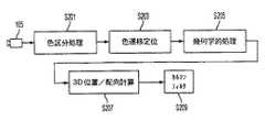
図6は、本発明の一実施形態による、ユーザによるユーザ入力デバイスの操作中に、ユーザ入力デバイスに対応するピクセル群をトラッキングして判別するために使用される機能ブロックを示すブロック図である。ブロックが表している機能は、図5のゲームコンソール510にあるMPU512によって実行されてもよいソフトウェアによって実装されることを理解されたい。さらに、図6のブロックが表している機能のすべてが、各実施形態で使用されるわけではない。 FIG. 6 is a block diagram illustrating functional blocks used to track and determine a group of pixels corresponding to a user input device during operation of the user input device by a user according to one embodiment of the present invention. It should be understood that the functions represented by the blocks are implemented by software that may be executed by the
最初に、カメラから入力されたピクセルデータは、入出力ポートインタフェース524を介してゲームコンソール510に送られ、これにより、以下のプロセスがゲームコンソール510で実行される。まず、画像の各ピクセルが、例えば、ラスタベースでサンプリングされると、色区分処理ステップS201が実行され、これによって、各ピクセルの色が決定されて、画像が色の異なるさまざまな2次元区分に分割される。次に、特定の実施形態で、色遷移定位ステップS203が実行され、これにより、色の異なる区分が隣接する領域がより詳細に決定されて、明確な色遷移が発生する画像の場所を特定する。次に、幾何学的処理S205のステップが実行され、このステップでは、実施形態に応じて、エッジ検出プロセスまたは面積の統計値の計算の実行が行われて、対象のオブジェクトのエッジに相当する線、曲線および/または多角形が代数的または幾何学的に定義される。 First, pixel data input from the camera is sent to the
ステップS207において、本発明の好ましい実施形態に関して後述するアルゴリズムを用いて、オブジェクトの3次元の位置およびオリエンテーション、即ち向きや方向が計算される。性能を向上させるため、3次元の位置および向きや方向のデータに対して、カルマンフィルタリングの処理ステップS209が実行される。このような処理は、オブジェクトがある時点に存在する位置を概算し、正しいデータセットから外れていると考えられる起こり得ない誤った測定値を除去するために実行されてもよい。カルマンフィルタリングを実行する別の理由として、カメラ105は画像を30Hzで生成するが、典型的なディスプレイは60Hzで動作するため、カルマンフィルタリングによって、ゲームプログラムのアクションを制御するために使用されるデータのギャップが埋められることが挙げられる。カルマンフィルタリングによる離散データのスムージングは、コンピュータビジョンの分野では周知であり、ここでは詳述しない。 In step S207, the three-dimensional position and orientation of the object, i.e., orientation and direction, are calculated using the algorithm described below with respect to the preferred embodiment of the present invention. In order to improve the performance, the Kalman filtering processing step S209 is performed on the data of the three-dimensional position, orientation, and direction. Such processing may be performed to approximate the position that an object exists at a point in time, and to remove possible erroneous measurements that are considered to be out of the correct data set. Another reason for performing Kalman filtering is that the
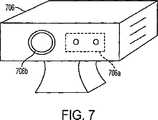
ユーザによって発せられる言語音や環境音などの音を受信し、その音を処理し、このような音に反応するようにユーザのアバターをプログラムすることも可能である。この実施形態において、図7の例で示すモニタ706が設けられてもよく、モニタ706は、画像キャプチャユニット706bおよび音声キャプチャユニット706bを含む。音源は、入力オブジェクト、デバイス、拍手、または足鳴らしによって生成されるノイズや任意のその他のノイズでありうる。次に、音声が、音声キャプチャユニット706aによってキャプチャされ、対話するためにコンピュータシステム102(図1)によって処理される。音声命令が識別できるように、音声認識が用いられてもよい。さらに、ユーザは、インターネットやネットワークと接続し、ゲームの対話性に直接的または部分的に関与するリモートユーザと通信状態にあってもよい。 It is also possible to program the user's avatar to receive sounds such as language sounds and environmental sounds emitted by the user, process the sounds, and react to such sounds. In this embodiment, a
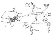
本発明の一実施形態によれば、音声キャプチャユニット706aは、コンピュータシステム102が特定の方向から届く音を選択できるようにする少なくとも2つのマイクロホンを含むように構成されてもよい。一実施形態において、コンピュータシステム102は、環境にある散乱音声が、対話型プログラムの実行を妨げたり混乱させたりしないように対話性の中心にない方向からの音を除去するようにプログラミングされる。同様の方法で、音声キャプチャユニットは、強度値を確実に識別するために、ターゲットとなる焦点ゾーンからの音声を分離しうる。以下に記載するように、焦点ゾーンは、画像キャプチャユニット706bの焦点であるアクティブ画像領域によって識別されてもよい。別の方法では、焦点ゾーンは、初期段階後にユーザに与えられたゾーンの選択肢から手動で選択することもできる。別の実施形態において、各音声は、モニタ706に対して特定の方向からくる音声として、複数のマイクロホンを用いて識別される。ユーザのアバターは、以下にさらに詳細に記載するように、例えば、音源の方へ頭部を向けることによって、特定の音声に応答するようにプログラムされてもよい。 According to one embodiment of the present invention, the
画像・音声キャプチャデバイス706は、画像キャプチャユニット706bと、音声キャプチャユニット706aとを含む。画像・音声キャプチャデバイス706は、画像フレームをディジタルキャプチャした後、さらに処理するために、それらの画像フレームをコンピュータシステム102(図1)に転送することが可能であってもよい。画像キャプチャユニット706bの一例は、ウェブカメラであってもよく、このウェブカメラは、ビデオ画像をキャプチャし、その後、インターネットなどのネットワーク上で引き続き格納したり通信したりするために、コンピュータデバイスにディジタル転送することが望ましい場合に一般に使用されている。識別とフィルタリングが可能であるように画像データがディジタル処理される限り、アナログであれディジタルであれ、他のタイプの画像キャプチャデバイスも想定される。1つの好ましい実施形態において、フィルタリングが可能なディジタル処理は、入力データの受信後にソフトウェアにおいて実行されてもよい。一対のマイクロホン(MIC1およびMIC2)を含む音声キャプチャユニット706aが示されている。マイクロホンは、画像・音声キャプチャデバイス706を構成するハウジングに一体化可能でありうる標準的なマイクロホンである。 The image /
図8は、音声Aおよび音声Bからの音源816がぶつかり合う場合の音声キャプチャユニット706aを示す。図示するように、音声Aは、可聴音を投射し、音声経路801aおよび801bに沿ってMIC1およびMIC2によって検出される。音声Bは、音声経路802aおよび802b上を進んで、MIC1およびMIC2の方に投射される。例示するように、音声Aの音声経路の長さは、音声経路802aおよび802bと比較すると異なるものであるため、比較的遅延する。次に、音声Aおよび音声Bの各々からの音声は、図9に示すボックス916において方向選択が発生しうるように、標準的な三角測量アルゴリズムを用いて処理される。MIC1およびMIC2からの音声の各々は、バッファ1および2(910a、910b)においてバッファリングされ、遅延線(912a、912b)を通過する。一実施形態において、バッファリングおよび遅延プロセスは、ソフトウェアによって制御されるが、同様の動作を取り扱えるように、ハードウェアをカスタム設計することもできる。三角測量に基づいて、方向選択916は、音源816の1つの識別および選択を引き起こす。 FIG. 8 shows the
MIC1およびMIC2の各々からの音声は、選択された音源の出力として出力される前に、ボックス914において合算される。このようにして、アクティブ画像領域の方向以外の方向からきた音声は、このような音源が、コンピュータシステム102(図1)によって処理を乱したり、ネットワークやインターネット上でビデオゲームを対話的にすることもある他のユーザとの通信を邪魔したりしないように除去される。この技術を利用したビデオゲームや他の応用は、音声キャプチャデバイスに対して所定の方向または選択された方向で焦点ゾーンから発せられる音声の強度値を確実に識別および定量化できる。 The audio from each of MIC1 and MIC2 is summed in
図10は、本発明の一実施形態による、画像・音声キャプチャデバイス706と併用されてもよいコンピュータシステム1050を示す。コンピュータシステム1050は、プロセッサ1052と、メモリ1056とを含む。バス1054が、プロセッサおよびメモリ1056と画像・音声キャプチャデバイス706とを相互接続する。メモリ1056は、対話型プログラム1058の少なくとも一部を含み、受信した音源データを処理するための選択的音源聴音ロジックまたはコード1060をさらに含む。焦点ゾーンが画像キャプチャユニット706bによって識別される場所に基づいて、焦点ゾーンの外側にある音源は、(例えば、プロセッサによって実行され、メモリ1056に少なくとも部分的に格納される)選択的音源聴音ロジック1060によって選択的にフィルタリングされる。コンピュータシステムは、最も簡単な形態で示されているが、命令を処理して、入射音源の処理を行い、選択的に聴音できる限り、任意のハードウェア構造を使用できるということが重要視される。 FIG. 10 illustrates a
コンピュータシステム1050はまた、バスを用いてディスプレイ110と相互接続されて示されている。この例において、焦点ゾーンは、音源Bの方へ焦点が向けられる画像キャプチャユニットによって識別されてもよい。音源Aなどの他の音源からくる音声は、音声が音声キャプチャユニット706aによってキャプチャされ、コンピュータシステム1050に転送されるとき、選択的音源聴音ロジック1060によって実質的に除去される。
1つの特定の例において、プレーヤが、別のユーザとインターネットまたはネットワーク上のビデオゲーム大会に参加でき、この場合、各ユーザは、主に、スピーカを用いることによって音を聴くことができる。スピーカは、コンピュータシステムの一部であってもよく、またはモニタ706の一部であってもよい。したがって、ローカルスピーカは、図4に示すように、音源Aを生成してもよいものとする。音源Aのローカルスピーカからきた音が対戦ユーザに戻らないようにするために、選択的音源聴音ロジック1060は、対戦ユーザに自らの音や声のハウリングが届かないように音源Aの音声を除去する。このようなフィルタリングを行うことで、プロセス中の不快なハウリングを有利に回避しながら、ビデオゲームとの接続中にネットワーク上で対話型の通信を行うことが可能である。 In one particular example, a player can participate in a video game tournament over the Internet or a network with another user, where each user can primarily listen to the sound using a speaker. The speaker may be part of the computer system or may be part of the
図11は、少なくとも4つのマイクロホン(MIC1〜MIC4)を含む例示的なモニタ706を示す。したがって、音声キャプチャユニット706aは、音源816(AおよびB)の場所を識別するために、粒度が良好な三角測量を行うことが可能である。すなわち、追加のマイクロホンを設けることによって、音源の場所をより正確に特定し、ひいては、対象ではない音源や、ゲームプレイにとって有害となりうる音源またはコンピュータシステムと対話的に有害となりうる音源を削除および除去することが可能である。図10に示すように、音源816(B)は、ビデオキャプチャユニット706bによって識別されている対象となる音源であってもよい。図10の例に続いて、図11は、音源Bが空間体積に対してどのように識別されるかを示す。 FIG. 11 shows an
音源Bが位置する空間体積は、焦点体積1174を画成する。焦点体積を識別することによって、特定の体積内にない(すなわち、ある方向にない)ノイズを削除または除去することが可能である。焦点体積1174を選択するために、画像・音声キャプチャデバイスモニタ706は、少なくとも4つのマイクロホンを含むことが好ましい。マイクロホンの少なくとも1つは、マイクロホンのうちの他の3つとは異なる平面にある。マイクロホンのうちの1つを画像・音声キャプチャデバイスモニタ706の平面1171に維持し、4つのうちの残りをモニタ706の平面1170に維持することによって、空間体積を画成することが可能である。 The spatial volume in which sound source B is located defines a
結果的に、近くにいる他の人(1176aおよび1176bで示す)からのノイズは、焦点体積1174に画成された空間体積内にないため除去される。さらに、スピーカ1176cによって示すように、空間体積の外側で生成されることもあるノイズも、空間体積の外側にあるため除去される。 As a result, noise from other people nearby (indicated by 1176a and 1176b) is removed because it is not within the spatial volume defined in the
以下、図12〜図14を参照しながら、フィルタリングアルゴリズムの例示的な実施について記載する。この実施例では、マイクロホンアレイを介したポータブル民生機器に関連するオーディオ入力システムが提供される。ボイス入力システムは、複数のノイズ信号からターゲットオーディオ信号を分離可能なものであってもよい。さらに、マイクロホンアレイが取り付けられたポータブル民生機器の動きには何ら制約がない。マイクロホンアレイフレームワークは、本発明の一実施形態において、4つのメインモジュールを含む。第1のモジュールは、音響エコーキャンセレーション(AEC)モジュールであってもよい。AECモジュールは、ポータブル民生機器が生成したノイズを打ち消すように構成されてもよい。例えば、ポータブル民生機器がビデオゲームコントローラである場合、ビデオゲームプレイに関連するノイズ、すなわち、音楽、爆発音、声などはすべて既知のものである。このように、マイクロホンアレイのマイクロホンセンサの各々からの信号に適用されるフィルタが、これらの既知のデバイス生成ノイズを除去してもよい。別の実施形態において、AECモジュールは、オプションであってもよく、以下に記載するモジュールとともに含まれなくてもよい。音響エコーキャンセレーションに関するさらなる詳細については、「Frequency-Domain and Multirate Adaptive Filtering」(John J. Shynk,IEEE Signal Processing Magazine, pp. 14-37,January 1992)の文献を参照されたい。この文献は、参照により本明細書に援用されたものとする。 In the following, an exemplary implementation of the filtering algorithm will be described with reference to FIGS. In this embodiment, an audio input system associated with a portable consumer device via a microphone array is provided. The voice input system may be capable of separating the target audio signal from a plurality of noise signals. Furthermore, there are no restrictions on the movement of portable consumer devices with microphone arrays attached. The microphone array framework includes four main modules in one embodiment of the present invention. The first module may be an acoustic echo cancellation (AEC) module. The AEC module may be configured to cancel noise generated by the portable consumer device. For example, if the portable consumer device is a video game controller, the noise associated with video game play, i.e. music, explosion sounds, voices, etc. are all known. Thus, a filter applied to the signal from each of the microphone sensors in the microphone array may remove these known device-generated noises. In another embodiment, the AEC module may be optional and may not be included with the modules described below. For further details on acoustic echo cancellation, see the literature in “Frequency-Domain and Multirate Adaptive Filtering” (John J. Shynk, IEEE Signal Processing Magazine, pp. 14-37, January 1992). This document is hereby incorporated by reference.
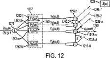
図12は、本発明の一実施形態による、リスニング方向からのものではない信号を抑制するように構成されたアレイビーム形成モジュールを示す簡易略図である。一実施形態において、ビーム形成は、フィルタ・加算ビーム形成に基づいたものであってもよい。信号通過フィルタとも呼ばれる有限インパルス応答(FIR)フィルタは、適応型のものであってもよいアレイ較正プロセスによって生成される。このように、ビーム形成は、本質的に、センサアレイを物理的に動かすことなく、音源信号2028の方へ、すなわち、リスニング方向にビームをトラッキングし方向付けうる適応ビーム形成器であってもよい。焦点方向からの信号を高めうる方法をさすビーム形成が、マイクロホンセンサ1212−1〜1212−Mを所望のターゲット信号にアルゴリズム的に(物理的ではなく)方向付けるためのプロセスとして考えられてもよいことは、当業者に明らかであろう。センサ1212−1〜1212−Mの視野方向は、ビーム形成方向またはリスニング方向と呼ばれることもあり、ランタイム時、固定されたものでも適応性のものであってもよい。 FIG. 12 is a simplified schematic diagram illustrating an array beamforming module configured to suppress signals that are not from the listening direction, according to one embodiment of the present invention. In one embodiment, beamforming may be based on filter and sum beamforming. Finite impulse response (FIR) filters, also called signal pass filters, are generated by an array calibration process that may be adaptive. Thus, beamforming may essentially be an adaptive beamformer that can track and direct the beam towards the source signal 2028, ie, in the listening direction, without physically moving the sensor array. . Beam forming, which refers to a method that can enhance the signal from the focal direction, may be considered as a process for algorithmically (rather than physically) directing the microphone sensors 1212-1 to 1212-M to the desired target signal. This will be apparent to those skilled in the art. The viewing direction of the sensors 1212-1 to 1212 -M may be referred to as a beam forming direction or a listening direction, and may be fixed or adaptive at runtime.
ビーム形成の基本的な考え方は、所望の音源からの音声信号が、異なる時間遅延でマイクロホンセンサアレイに届くというものである。アレイの幾何学的配置は予め較正されているため、音源とセンサアレイとの間の経路長の相違は、既知のパラメータである。したがって、異なるセンサからの信号を時間的に整合するために、相互相関と呼ぶプロセスが用いられてもよい。さまざまなセンサからの時間的整合信号は、ビーム形成方向に従って加重される。次に、加重信号は、センサ固有のノイズキャンセレーションセットアップの点でフィルタリングされ、すなわち、各センサが、整合フィルタF11242−1〜FM1242−Mと呼ぶフィルタに関連付けられてもよく、各フィルタは、信号通過フィルタ1262に含まれる。次に、各センサからのフィルタリング信号は、出力Z(ω,θ)を生成するために、モジュール1272を介して合算される。上述したプロセスは、自動相関と呼ばれてもよいことを認識されたい。さらに、ビーム形成方向に沿って存在しない信号が、時間軸に沿って整合されないままであるため、これらの信号は、平均化によって減衰される。アレイベースのキャプチャシステムには共通していることだが、所望の空間方向(直線の幾何学的配置を用いる)または空間体積(凸幾何学的配置を用いる)から音声をキャプチャするためのマイクロホンアレイの全性能は、音源の位置を特定しトラッキングする能力に依存する。しかしながら、複雑な残響ノイズがある環境、例えば、ビデオゲーム環境では、環境固有のパラメータを統合することなく、一般的に音声位置特定トラッキングシステムを構築することが現実的に実行不可能である。 The basic idea of beamforming is that the audio signal from the desired sound source reaches the microphone sensor array with different time delays. Since the array geometry is pre-calibrated, the path length difference between the sound source and the sensor array is a known parameter. Thus, a process called cross-correlation may be used to temporally match signals from different sensors. The time alignment signals from the various sensors are weighted according to the beamforming direction. The weighted signal is then filtered in terms of sensor-specific noise cancellation setup, i.e., each sensor may be associated with a filter referred to as a matched filter F112242-1-FM1242-M, each filter being a signal
さらに図12を参照すると、適応ビーム形成は、他の形態において、2部構成のプロセスとして説明されてもよい。第1部において、側面衝突ノイズは、遠距離にあるものとされる。すなわち、音源1228からマイクロホンの中心1212−1〜1212−Mまでの距離は十分に長いため、音源1228は、最初、マイクロホンセンサの各々の垂線に位置すると仮定されてもよく、例えば、マイクロホンセンサ1212−mを参照すると、音源は、垂線1236に沿った位置にあることになる。このように、側面衝突ノイズは、この場合、本明細書においてF1と呼ぶフィルタを適用することによって高められるものとしてもよい。次に、周期的に較正されてもよい信号通過フィルタが、マイクロホンセンサアレイが動きに適応できるようにする、F2と呼ばれるファクタを決定するように構成されてもよい。F2の決定については、適応アレイ較正モジュールを参照しながらさらに説明する。一実施形態において、信号通過フィルタは、100ミリ秒ごとに較正されてもよい。このように、信号通過フィルタは、100ミリ秒ごとに固定ビーム形成に適用されてもよい。一実施形態において、整合フィルタ1242−1〜1242−Mは、各マイクロホンにステアリングファクタを供給することによって、ライン1238−1〜1238−Mによって示されるリスニング方向を調節する。正弦波の遠視野平面波が、図12の入射角θでセンサへ伝播すると考えると、2つの隣接するセンサ間の距離dを平面波が進行するための時間遅延は、dmcosθによって与えられるものであってもよい。固定ビーム形成に関するさらなる詳細については、「Beamforming: A Versatile Approach to Spatial Filtering」(Barry D. Van Veen and Kevin M. Buckley, IEEE ASSP MAGAZINE April 1988)の文献を参照されたい。この文献は、参照により本明細書に援用されたものとする。 Still referring to FIG. 12, adaptive beamforming may be described in another form as a two-part process. In the first part, the side collision noise is assumed to be at a long distance. That is, since the distance from the
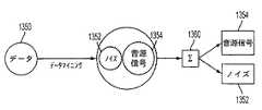
図13は、オーディオ信号のノイズと音源信号成分とを分離するためのブラインド音源分離方式を示す高水準略図を示す。オーディオ信号内の音源信号およびノイズが明確に分からないこともあることを認識されたい。しかしながら、音源信号とノイズの特性が異なることは知られている。例えば、第1のスピーカのオーディオ信号は、第2のスピーカのオーディオ信号とは区別され、その理由として、スピーカの声が異なることと、ノイズの種類も異なることとが挙げられる。このように、ノイズおよび音源信号を含む入射オーディオ信号を表すデータ1350は、データマイニング動作によって、ノイズ成分1352および音源信号1354に分離されてもよい。次に、分離フィルタ1360は、音源信号1350をノイズ信号1352から分離する。 FIG. 13 shows a high-level schematic diagram showing a blind sound source separation method for separating noise and sound source signal components of an audio signal. It should be appreciated that the sound source signal and noise in the audio signal may not be clearly known. However, it is known that the sound source signal and noise characteristics are different. For example, the audio signal of the first speaker is distinguished from the audio signal of the second speaker, because the voice of the speaker is different and the type of noise is also different. Thus, the
当業者であれば、データマイニングを実行するための1つの方法が、本発明の一実施形態による二次統計によって、データを解析し、独立成分を見つける独立成分分析(ICA)によるものであってもよいことを認識するであろう。このように、さまざまな音声を区別する音紋をキャプチャするために、データの特性を記述または規定するように二次統計が算出されてもよい。次に、分離フィルタは、音源信号とノイズ信号とを分離するようにされてもよい。音紋の計算は、周期的に実行されてもよいことを認識されたい。このように、ブラインド音源分離を利用するこの適応アレイ較正プロセスによって、リスニング方向が各期間に調節されてもよい。信号が分離フィルタ1360によって分離されると、トラッキング問題が解決されるであろうことは、当業者には明らかであろう。すなわち、センサアレイの複数のマイクロホンに基づいて、遅延の到着時間が、音源信号1354をトラッキングするさいに使用するために決定されてもよい。当業者であれば、上記で二次統計と呼んだものは、自動相関または相互相関方式と呼ばれてもよいことを認識するであろう。二次統計を用いたブラインド音源分離に関するさらなる詳細については、「System Identification Using Non-Stationary Signals」(O. Shalvi and E. Weinstein, IEEE Transactions on Signal Processing, vol-44(no.8): 2055-2063, August, 1996)の文献を参照されたい。この文献は、参照により本明細書に援用されたものとする。 One skilled in the art is one method for performing data mining is by independent component analysis (ICA), which analyzes data and finds independent components by secondary statistics according to one embodiment of the present invention. You will appreciate that. In this way, secondary statistics may be calculated to describe or define the characteristics of the data in order to capture a voiceprint that distinguishes various sounds. Next, the separation filter may be configured to separate the sound source signal and the noise signal. It should be appreciated that the calculation of the voiceprint may be performed periodically. Thus, the listening direction may be adjusted for each period by this adaptive array calibration process utilizing blind source separation. It will be apparent to those skilled in the art that once the signal is separated by
図14は、適応ノイズキャンセレーションを組み込んだマイクロホンアレイフレームワークを示す略図である。ノイズおよび音源信号を含むオーディオ信号1466が、ポータブル民生機器102、例えば、ビデオゲームコンソールまたはコンピュータデバイスに取り付けられたもよいマイクロホンセンサアレイを介して受信されてもよい。次に、ポータブル民生機器102によって受信されたオーディオ信号は、音響エコーキャンセレーション(AEC)モジュール1468を介して予め処理されてもよい。この場合、音響エコーキャンセレーションは、参照により本明細書に援用されたものとする米国特許出願第10/650,409号明細書に一例として記載されているように実行されてもよい。マイクロホンアレイにあるマイクロホンセンサの数に対応する信号Z1〜ZMが生成され、チャネル1470−1〜1470−M上で分配される。チャネル1470−1が基準チャネルであってもよいことを認識されたい。次に、対応する信号は、フィルタ・加算モジュール1262に送られる。フィルタ・加算モジュール1262が、図20を参照しながら上述したような適応ビーム形成を実行することを認識されたい。同時に、チャネル1470−1〜1470−Mからの信号が、ブロックフィルタ1464に送られる。 FIG. 14 is a schematic diagram illustrating a microphone array framework incorporating adaptive noise cancellation.
ブロックフィルタ1464は、ターゲット信号がノイズと見なされる場合、逆ビーム形成を実行するように構成されてもよい。このように、ブロックフィルタ1464は、音源信号を減衰し、ノイズを高める。すなわち、ブロックフィルタ1464は、適応ビーム形成プロセスによって形成された較正係数F2の逆数と見なされてもよい較正係数F3を決定するために較正されてもよい。当業者であれば、図13を参照しながら言及した適応アレイ較正が、本明細書に記載するプロセスの背景で起こることを認識されたい。フィルタ・加算モジュール1262およびブロックフィルタモジュール1464が、分離フィルタ1360を構成する。次に、ノイズが高められた信号U2〜UMが、対応する適応フィルタ1475−2〜1475−Mのそれぞれに送信される。適応フィルタ1475−2〜1475−Mは、適応フィルタモジュール1474に含まれる。この場合、適応フィルタ1475−2〜1475−Mは、モジュール1476の加算動作の対応する信号を整合するように構成される。当業者であれば、ノイズは定常のものでなくてもよく、したがって、信号は、加算動作の前に整合されなければならないことを認識するであろう。
次に、図14をさらに参照すると、モジュール1476の加算動作からの信号は、加算動作モジュール1478を介して低減されたノイズ信号を与えるために、モジュール1472の加算動作からの信号出力と結合されてもよい。すなわち、モジュール1472の高められた信号出力は、所望の音源信号を高める方法でモジュール1476からの高められたノイズ信号と結合されてもよい。ブロック1480が、適応ノイズキャンセレーション動作を表すことを認識されたい。さらに、背景で行われていたアレイ較正は、一実施形態において、検出された信号対雑音比がゼロデシベルを超えるものである限り、100ミリ秒ごとに起こるものであってもよい。上述したように、アレイ較正は、フィルタ・加算ビーム形成器1262に使用される信号通過フィルタと、信号対雑音比が−100デシベル未満のものであってもよい純干渉を生成する信号ブロックフィルタ1464とを更新する。 Referring now further to FIG. 14, the signal from the add operation of
一実施形態において、マイクロホンセンサアレイの出力信号は、ベイズの統計モデリングによる人依存のボイススペクトルフィルタリングに基づいて、声の質をさらに上げるために、後処理モジュールに送られてもよい。ボイススペクトルフィルタリングに関してのさらなる情報については、「Speech Enhancement Using a Mixture- Maximum Model」(David Burshtein, IEEE Transactions on Speech and Audio Processing vol. 10, No. 6, September 2002)を参照されたい。この文献は、参照により本明細書に援用されたものとする。本明細書において記述する信号処理アルゴリズムは、周波数領域で実行されることを認識されたい。さらに、リアルタイム信号応答に達するために、高速かつ高効率の高速フーリエ変換(FFT)が適用されてもよい。一実施形態において、実装するソフトウェアには、信号入力チャンクごとに1024の窓長を有する25FFT演算が必要である(16kHzサンプリングレートで512信号サンプル)。音響エコーキャンセレーションおよびベイズモデルベースのボイススペクトルフィルタリングを適用せずに、等間隔の直線形状に設けられた4センサマイクロホンアレイの例示的な場合において、関与する全計算は、約250メガ浮動小数点演算(250メガフロップス)であってもよい。 In one embodiment, the output signal of the microphone sensor array may be sent to a post-processing module to further improve voice quality based on person-dependent voice spectrum filtering with Bayesian statistical modeling. For more information on voice spectrum filtering, see "Speech Enhancement Using a Mixture-Maximum Model" (David Burshtein, IEEE Transactions on Speech and Audio Processing vol. 10, No. 6, September 2002). This document is hereby incorporated by reference. It should be appreciated that the signal processing algorithms described herein are performed in the frequency domain. Furthermore, a fast and efficient fast Fourier transform (FFT) may be applied to reach a real-time signal response. In one embodiment, the software to be implemented requires 25 FFT operations with a window length of 1024 for each signal input chunk (512 signal samples at 16 kHz sampling rate). In the exemplary case of a four-sensor microphone array arranged in an evenly spaced linear shape without applying acoustic echo cancellation and Bayesian model-based voice spectrum filtering, the total computation involved is approximately 250 mega floating point operations. (250 megaflops).
図14をさらに参照すると、分離フィルタ1360が、QR直交化法によって、値域と零空間にある2つの直交成分に分解されてもよい。すなわち、信号ブロックフィルタ係数F3は、零空間から得られてもよく、信号通過フィルタ係数F2は、値域空間から得られてもよい。このプロセスは、一般化サイドローブキャンセラ(GSC)アプローチとして特徴付けられてもよい。GSCアプローチのさらなる詳細については、上記に参照によりすでに援用した「Beamforming: A Versatile Approach to Spatial Filtering」というタイトルの文献を参照されたい。 Still referring to FIG. 14, the
上述した実施形態には、高ノイズ環境においてオーディオ入力を与えるための方法およびシステムが記載されている。オーディオ入力システムは、ビデオゲームコントローラ、例えば、ソニー・プレイステーション2(登録商標)ビデオゲームコントローラや任意のその他の適切なビデオゲームコントローラに備えられてもよいマイクロホンアレイを含む。マイクロホンアレイは、ビデオゲームコントローラの動きに何ら制約を課すことがないように構成されてもよい。マイクロホンアレイのマイクロホンセンサによって受信された信号は、前景スピーカまたはオーディオ信号と、室内反響を含むさまざまな背景ノイズとを含むように仮定される。さまざまなセンサからの背景と前景との間の時間遅延が異なることもあるため、周波数スペクトル領域における二次統計は、互いから独立したものであり、したがって、信号は、周波数成分ベースで分離されてもよい。次に、分離された信号周波数成分は、前景の所望のオーディオ信号を再構築するように再結合される。本明細書に記載する実施形態において、ビデオゲームに命令を発したり、ノイズ環境内で他のプレーヤと通信したりするためのリアルタイムボイス入力システムが定義されることをさらに認識されたい。他の実施形態において、オーディオプロセッサは、特定の音声の発生源方向を識別可能であり、その情報をソフトウェアに渡すことで、以下に記載するように、アバターの頭部を音のする方へ向け、例えば、ドアが閉まる音など、音の種類が識別されれば、その音の種類に応答するようにアバターを方向付けることによって、音に応答することができる。 The above described embodiments describe a method and system for providing audio input in a high noise environment. The audio input system includes a microphone array that may be included in a video game controller, such as a
ビデオゲームコントローラが、典型的に、ゲーム内でのアクションを制御するために、ビデオゲームプログラムに入力を与えるためのボタン、つまみ、および/またはジョイスティックを有するハンドヘルドデバイスであってもよい。空間内でのコントローラの動きおよび/または回転を検知することによって、コントローラにさらなる機能を追加することが望ましい。このようにして、ユーザが、スクリーン上のアクションに対する感情的な応答としてコントローラを回したり動かしたりすると、ユーザのアバターも同じように動くことができる。例えば、ユーザは、コントローラを操作して仮想レースカーを操縦しているとき、特に急なカーブに対しての感情的な応答として、コントローラデバイス全体を傾けることもある。次に、図1〜図14を参照しながら上述したように、この動きは、画像キャプチャデバイスによって検知されうる。 The video game controller may typically be a handheld device having buttons, knobs, and / or joysticks for providing input to the video game program to control actions within the game. It would be desirable to add further functionality to the controller by sensing the movement and / or rotation of the controller in space. In this way, if the user turns or moves the controller as an emotional response to an action on the screen, the user's avatar can move as well. For example, when operating a controller and manipulating a virtual race car, a user may tilt the entire controller device, particularly as an emotional response to a sharp curve. This motion can then be detected by the image capture device, as described above with reference to FIGS.
従来、ビデオゲームコントローラは、ケーブルを通して、または利用可能な赤外線または高周波数(RF)インタフェースの1つ以上を用いてワイヤレスでアナログ信号および/またはディジタルデータのストリームを提供する。複数プレーヤゲームの場合、コンピュータシステムを備える電子通信機器(例えば、ゲームコンソール)に、2つ以上のコントローラが配置されてもよい。プログラムと対話する人にはそれぞれ、番号、例えば、「プレーヤ1」、「プレーヤ2」などが割り当てられてもよい。ゲームコントローラがシステムに接続されると、各ユーザは、コントローラが接続されているポート番号に従って、番号が割り当てられうる。このように、コンピュータゲームに4つのポートがあれば、プレーヤ1は、ポート番号1に接続され、プレーヤ2は、ポート番号2に接続され、以下同様である。ワイヤレスコントローラにより、プレーヤは、ワイヤレスチャネルや他のハンドシェイクプロトコル機構に基づいて、自分のプレーヤ番号を選択でき、コントローラは、プレーヤ1、プレーヤ2などと識別することができる。 Traditionally, video game controllers provide a stream of analog signals and / or digital data over a cable or wirelessly using one or more of the available infrared or high frequency (RF) interfaces. In the case of a multiplayer game, two or more controllers may be arranged in an electronic communication device (for example, a game console) provided with a computer system. Each person interacting with the program may be assigned a number, for example, “
図15および図16は、画像キャプチャデバイス105(図1)と対話する例示的なコントローラ1500を示す。コントローラ1500は、さまざまなボタンおよびジョイスティックを含む複数の対話型デバイスを含むインタフェース1502を含む。本明細書に記述するコントローラは、有線または無線のいずれかでありうる。ワイファイ、ブルートゥース(登録商標)などの技術、IR、音声、および発光体は、ゲームコンソールなどのコンピュータと対話するように機能するものであってもよい。一実施形態において、コントローラ1500は、LEDアレイ1505を有する。LEDアレイは、さまざまなレイアウトで構成され、例えば、架空の矩形状または正方形状の結合枠の頂点に各LEDが位置付けられてもよい2×2スタックで構成されてもよい。画像キャプチャデバイスによって生じる画像平面に投射されるときに結合枠の位置および変形をトラッキングすることによって、その変換および変形は、コントローラの位置および向きや方向の情報を解読するために、ビデオアナライザにおいて解析されてもよい。LEDアレイ1505は、赤外線または可視光を生成してもよい。画像キャプチャデバイス105(図1)は、さまざまな他の本発明の実施形態を参照しながら上述したように、LEDアレイ1505を識別しうる。各コントローラは、例えば、ユーザがプレーヤ番号1〜4を選択できるスイッチ1510を使って、プレーヤ1からプレーヤ4として指定されてもよい。各プレーヤ番号の選択は、LEDアレイ1505によって照明されるLEDの固有パターンまたは変調に対応する。例えば、プレーヤ1の場合、1番目、3番目、および5番目のLEDが照明される。このようなプレーヤ情報は、複数のビデオフレームにわたって経時的に繰り返し符号化され送信されてもよい。コントローラまたはデバイスLEDが、トラッキングモードと送信モードとの間でスイッチ可能であるように、交互配置に係合することが望ましいこともある。トラッキングモードでは、サイクルの第1の部分の間、すべてのLEDがオンにされてもよい。送信モードでは、サイクルの第2の部分の間、情報がLEDによって変調されてもよい。時間の経過とともに、LEDは、トラッキングおよび通信情報を、ビデオアナライザまたは信号を受信可能な適切なデバイスに送信する。送信モードにおいて、LEDは、プレーヤのIDを表す情報を符号化してもよい。周期およびデューティーサイクルは、トラッキング速度、発光体条件、コントローラの数などに対応するように選択されてもよい。通信およびトラッキング情報を交互に配置することによって、ビデオキャプチャデバイスに、各コントローラに対してトラッキングパラメータを算出し、コントローラ間を区別するのに十分な情報が供給されてもよい。このような区別は、位置および向きや方向やコントローラの動きの他の計測値をモニタリングおよびトラッキングするときに、各物理的コントローラを隔離するためにビデオアナライザにおいて用いられてもよい。 15 and 16 illustrate an
送信モードにおいて、命令や状態情報を含む他の情報が、コントローラまたはデバイスLEDによって、既知の符号化および変調方式に従って送信されてもよい。受信機側では、ビデオキャプチャデバイスに結合されたビデオアナライザが、LEDの状態と同期し、その状態をトラッキングし、その情報およびコントローラの動きを復号化してもよい。送信モードサイクルにおいてフレームにわたってデータを変調することによって、高い帯域幅が達成されてもよいことが知られている。 In transmission mode, other information including instructions and status information may be transmitted by the controller or device LED according to known coding and modulation schemes. On the receiver side, a video analyzer coupled to the video capture device may synchronize with the state of the LED, track that state, and decode the information and controller movement. It is known that high bandwidth may be achieved by modulating data across frames in a transmission mode cycle.
インタフェース1502とのユーザ対話により、LEDアレイ1505にあるLEDの1つ以上の色が、変調および/または変更されてもよい。例えば、ユーザがジョイスティックを動かすと、LEDが、輝度を変更し、または情報を送信してもよい。さらに、各ボタンは、LEDアレイ1505にあるLEDの1つ以上の色または強度の変更にマッピングされてもよい。 User interaction with the
コントローラ1500が、3次元空間で動き回され、回転、揺れ、またはピッチ方向(図19を参照しながら以下にさらに詳細に説明する)の1つで回転すると、コンピュータシステム102(図1)と併せて画像キャプチャデバイス105が、これらの変更を識別し、画像平面上の動きを記述するための2次元ベクトル、または3次元空間での動きを記述するための3次元ベクトルとを生成可能であってもよい。ベクトルは、相対運動を記述する一連の座標および/または画像キャプチャデバイス105に対しての絶対位置として与えられうる。当業者に明らかなように、画像キャプチャデバイス105の見通し線に垂直な平面(画像平面)上での動きが、画像キャプチャゾーン内における絶対位置によって識別されえ、その一方で、画像キャプチャデバイス105により近い位置のコントローラ1500の動きは、広がったように見えるLEDアレイ1505によって識別可能であり、すなわち、画像平面上での第1のLEDと最後のLEDとの間の距離が、画像キャプチャデバイスからの距離を算出するために測定されうる。 When the
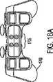
図17および図18aは、矩形状の構成のLED1705を有するコントローラ1700を示し、コントローラ1700が3つの各軸の周りで回転する動きを検出できる。LEDだけが示されているが、これは、例示的な目的でしかなく、平面上に分布され、同一線上には分布されない任意の数のLEDも可能である。コントローラ1700が、前方または後方に位置を変えることもあるため、上部および下部LEDは、左側および右側LEDが同じ距離引き離されたままの状態で、互いにより近づけられてもよい。同様に、コントローラ1700が、左または右に揺れると、左側および右側LEDは、上部および下部LEDが同じ距離引き離されたままの状態で、互いに近づくようになる。コントローラ1700の回転運動が、画像平面上でのLEDの向きを識別することによって検出されうる。コントローラが、見通し線に沿って画像キャプチャデバイス105に近づく方向に移動するとき、すべてのLEDは、広がっているように見える。最後に、画像平面に沿ったコントローラの動きは、画像平面上でのLEDの場所を識別し、それによって、x軸とy軸のそれぞれに沿った動きを識別することによってトラッキングされうる。図15および図16を参照しながら上述したように、LED変調が、インタフェース1702とのユーザ対話を識別するように使用されうる。 FIGS. 17 and 18a show a
図18bは、別の実施形態によるコントローラ1820を示し、コントローラ1820は、LED1822と、スピーカ1824と、マイクロホン1826とを組み込んでいる。LED1822は、画像キャプチャデバイスを用いて位置および向きや方向情報を提供し、スピーカ1824が、可聴音または超音波を生成でき、図7〜図14を参照しながら上述したようなオーディオモニタを用いて、音響効果および/または通信を与える。マイクロホン1826は、システムに音声入力を与え、音声命令を発するために、またはオンラインの複数プレーヤ環境において他のプレーヤと通信するために使用されうる。 FIG. 18 b shows a
図18cは、コントローラ1830の背面パネル上の中心に位置するスピーカ1834とともに、矩形状の構成でLED1832を有するコントローラ1830を示す。図18dは、弧状に配設された5つのLEDアレイ1842を有するコントローラ1840を示す。図18eは、幅広い矩形状に配設されたLEDを有するコントローラ1850を示す。図18fは、まとめて配設された6つのLED1862を有するコントローラ1860を示す。当業者であれば、他のLED構成が可能であることを認識されたい。 FIG. 18 c shows a
図19は、多数の制御装置および動作検知デバイス1905を含むインタフェース1902を有するコントローラ1900を示す。一実施形態において、動作検知デバイス1905が、3軸加速度計であってもよい。加速度計が、一般に、電子機器の分野において既知のものであり、典型的に、運動量の変化に応答する構造と、その応答を検出するセンサとを有する小さな固体デバイスを含む。小型加速度計は、回転運動だけでなく、並進運動を検知するために利用可能である。並進運動は、x軸、y軸、およびz軸に沿った運動である。回転運動は、x軸、y軸、およびz軸の1つ以上の周りの回転である。並進運動を検出する加速度計は、重力の引っ張り方向を検知し、したがって、重力の引っ張りに対してデバイス(ゲームコントローラなど)の絶対的な向きや方向を識別しうる。コントローラ1900は、コントローラ1900内に含まれる回路(図示せず)によって受信されたディジタルデータを生成する並進検知加速度計1905を含む。ディジタルデータは、デバイスにかかる重力による引張り力から決定可能な、デバイスの並進運動ベクトルおよび向きや方向に変換されうる。このようにして、回路は、コントローラ1900の動きおよび向きや方向を識別し、ケーブル、赤外線、または無線接続などを介して、当業者に一般に既知の方法で、このデータを、インタフェース1902のさまざまな制御装置とユーザ対話を表す他のデータとともに、ゲームコンソールに送信する。また、画像キャプチャデバイスによって見るためのLED変調にデータを符号化することも可能である。デバイスによってキャプチャされる動きは、絶対位置および向きや方向の情報(初期位置を発生源とする)および/または位置および向きや方向の変化として表しうる。 FIG. 19 shows a
図20は、コントローラ2000の動きをコンピュータプログラムに伝える例示的なプロシージャを示すフローチャート2000を示す。プロシージャは、図示するように、開始ブロック2002によって始まり、ゲームコントローラの動きが検出されてもよい動作2004に進む。一実施形態において、加速度計を用いて検出可能であるコントローラの運動量の変化を検出することによって、動きを検出してもよい。次に、運動量の変化は、運動ベクトルおよび/または初期発生源からの絶対位置と、重力の引っ張りを表すベクトルに変換され、コントローラ2000の向きや方向を識別する。運動、位置、および方向ベクトルは、一連の座標として表されうる。動作2004において、ゲームコントローラ2000の動きを検出した後、プロシージャは、検出された動きを表すデータが、データを要求したプログラムに送られてもよく、または他の方法でデータを受信してもよい。 FIG. 20 shows a
特定の実施形態において、コントローラを含む1つ以上の入力オブジェクトのコントローラプレーヤ番号、向きや方向、および/または位置を決定するための上述した画像またはオーディオ処理機能が、コンピュータシステム上で実行するプロセスにおいて実行されてもよい。コンピュータシステムはまた、ゲームアプリケーションであってもよいメインプロセスを実行してもよく、このプロセスでは、強度値、コントローラプレーヤ番号、コントローラを含む1つ以上の入力オブジェクトの向きや方向および/または位置、コントローラの作動などを含むデータなど、画像またはオーディオ処理から生成されたデータを要求し、または他の方法で受信する。さまざまな実施形態において、画像および/またはオーディオ処理機能を実行するプロセスは、ビデオカメラまたはビデオ/オーディオモニタリングデバイス用のドライバであってもよく、ドライバは、当業者に一般に既知であり理解されるように、実装時固有のものであってもよい任意のタイプのプロセス間の通信を介して、データをメインプロセスに与える。画像またはオーディオ処理を実行するプロセスは、ゲームや他のソフトウェアを実行するものと同じプロセッサまたは異なるプロセッサで実行される。同じプロセスにおいて、例えば、手続き呼出しを用いて、画像またはオーディオ処理と、ゲーム機能との両方に共通したプロセスを有することも可能である。したがって、「プログラムに」強度値やその他の情報が与えられてもよいことを本明細書において述べていることもあるが、本発明は、単一のプロセスで画像処理機能とゲーム機能との両方を実行しうるように、手続き呼出しまたはその他のソフトウェア機能を用いて、プロセスの1つのルーチンにこのようなデータを与えることを伴いとともに、これらの機能を異なるプロセスに分離することで、共通のプロセッサコアまたは複数のプロセッサコアに実行してもよい1つ以上のプロセスが、本明細書に記載するように、画像および/またはオーディオ処理を実行し、別のプロセスがゲーム機能を実行することを認識されたい。 In certain embodiments, in the process that the above-described image or audio processing functions for determining the controller player number, orientation, orientation, and / or position of one or more input objects including a controller are performed on a computer system. May be executed. The computer system may also execute a main process, which may be a game application, in which the intensity value, controller player number, orientation or direction and / or position of one or more input objects including the controller, Request or otherwise receive data generated from image or audio processing, such as data including controller activity. In various embodiments, the process of performing image and / or audio processing functions may be a driver for a video camera or video / audio monitoring device, which is generally known and understood by those skilled in the art. In addition, data is provided to the main process via communication between any type of process that may be specific to the implementation. The process of performing image or audio processing is performed on the same or different processor that executes the game or other software. In the same process, it is possible to have a process that is common to both image or audio processing and game functions, for example using procedure calls. Thus, although it may be stated herein that intensity values and other information may be given to the “program”, the present invention provides both image processing and game functions in a single process. To provide such data to one routine of a process using procedure calls or other software functions, and by separating these functions into different processes, a common processor Recognize that one or more processes that may execute on a core or multiple processor cores perform image and / or audio processing as described herein, and that another process performs game functions. I want to be.
図21は、本発明の一実施形態による言語的および非言語的コミュニケーションを改善し高めるためのシステムの高水準概要の簡易ブロック図である。図21に示すように、システム2100が、少なくとも1つのコントローラ2102A、少なくとも1つの周辺マイクロホン2102B、少なくとも1つのビデオカメラ2102C、および少なくとも1つのプレーヤマイクロホン2102Dからデータを入力可能である。 FIG. 21 is a simplified block diagram of a high level overview of a system for improving and enhancing linguistic and non-verbal communication according to one embodiment of the present invention. As shown in FIG. 21, the
ビデオカメラ2102Cからのビデオ入力は、最初、入力ユニット104に送られる。入力ユニットは、回路またはソフトウェア制御されたドライバの形態のものでありうる。次に、ビデオ入力は、ビデオキャプチャユニット2112に送られ、ビデオ認識・トラッキングユニット2116によってさらに処理される。ビデオ認識・トラッキングユニット2116は、ユーザの動きとともに、ユーザの顔の特徴や身体部位を認識しうる。さらに、ビデオ認識・トラッキングユニット2116は、背景環境、およびキャプチャ画像内にあるその他の要素をキャプチャ可能であってもよい。フレームプロセッサ2120が、ビデオ認識・トラッキングユニット2116からの出力を用いて、ビデオ効果ライブラリ2108からのビデオを加えて画像を補いうる。ビデオ効果ライブラリ2108は、所定のビデオ効果2108Aおよびカスタムビデオ効果2108Bとして示す少なくとも2つのライブラリを含み、ユーザによって選択的に適用され、またはシステム2100によって自動的に供給されうる。ビデオ効果ライブラリ2108は、ライブラリに所定のカスタムビデオ効果がある限り、ライブラリの数を増減させることも可能である。動作中、フレームプロセッサは、ビデオ出力2132として示され、ユーザに表示される最終画像を算出し出力するグラフィックプロセッサ/レンダラ2124にデータを出力する。グラフィックプロセッサ/レンダラ2124はまた、システム2100の状態に関する情報を通信リンク2126に送る。 Video input from the
周辺マイクロホン2102Bおよびプレーヤマイクロホン2102Dからのオーディオ入力は、最初、入力ユニット2104を通過し、次に、キャプチャされたデータを音声認識ユニット2114に送ってもよい音声キャプチャユニットによってキャプチャされてもよい。次に、音声データは、音響効果ライブラリ2106からの入力を受信しうる音声プロセッサ2118に送られてもよい。音響効果ライブラリ2106は、所定の音響効果2106Aおよびカスタム音響効果2106Bとして示す少なくとも2つのライブラリを含み、ユーザによって選択的に適用され、またはシステム2100によって自動的に供給されうる。音響効果ライブラリは、ライブラリに所定のカスタムオーディオ効果がある限り、ライブラリの数を増減させることも可能である。一実施形態において、音声プロセッサ2118は、オーディオ出力2130として示すシステム2100の最終混合音声を出力し、システム2100の状態に関する情報を通信リンク2126に送る。 Audio inputs from
一実施形態において、通信リンク2126は、システム2100をネットワーク2128に接続し、このネットワーク2128は、システム2100と対話可能であり、リモートユーザ(図示せず)によって作動されたリモートシステム2150とシステム2100とを接続しうる。図21は、ネットワーク2128を介して単一のリモートシステム2150に接続されているシステム2100を示すが、複数のリモートシステム2150およびそれらに対応するユーザが、ネットワーク2128を介してシステム2100に接続されてもよいことを理解されたい。リモートシステム2150は、システム2100から受信したデータに基づいて、システム2100の状態を理解可能である。リモートシステム2150は、オーディオ出力2154およびビデオ出力2152を生成する前に、システム2100の状態に関する情報と、リモートユーザからの入力とを結合する。 In one embodiment, communication link 2126 connects
図22Aは、本発明の一実施形態による、レースの対戦中の2人のプレーヤから見たスクリーンを示す。運転シミュレーションゲームを基にしたこの例で、本発明に関するさらなる本質が分かるであろう。この例では、2人のプレーヤが、ゲームプレイ中にアバターに感情的特徴を与えうる運転シミュレーションを用いて、レースの対戦をしている。プレーヤ1およびプレーヤ2は、物理的に異なる場所にいてもよく、各プレーヤのゲーム状態に関するデータを送信するためにインターネットを使用してもよい。各プレーヤのそれぞれの場所にあるマイクロホンおよびカメラは、ゲームプレイに対するプレーヤの反応をモニタリングしてもよい。一実施形態において、マイクロホンは、プレーヤの可聴反応をモニタリングでき、また一方で、カメラは、ゲームプレイに反応してプレーヤの物理的な動きをモニタリングしうる。他の実施形態において、コントローラは、コントローラの位置およびピッチの変化速度、回転、揺れ、加速、および相対運動に関するデータをコンピュータシステムに中継するように構成されうる。各プレーヤは、カスタムアバターを有してもよく、各プレーヤは、対戦相手のアバターを自らのスクリーン上で見ることができる。 FIG. 22A shows a screen viewed from two players during a race match, according to one embodiment of the present invention. This example, based on a driving simulation game, will show further essence regarding the present invention. In this example, two players are competing in a race using a driving simulation that can give emotional characteristics to an avatar during game play.
一実施形態において、ビデオスクリーン2200が、2つのウィンドウを含んでもよく、ウィンドウ2204は、ゲーム中にプレーヤ1が見ているものを示し、ウィンドウ2202は、プレーヤ2のアバターを示す。また、ビデオスクリーン2206は、2つのウィンドウを含んでもよく、ウィンドウ2210は、ゲーム中にプレーヤ2が見ているものを示し、ウィンドウ2208は、プレーヤ1のアバターを示す。異なる実施形態において、2人以上のオンラインの対戦相手を表すためのアバターウィンドウが複数あってもよい。別の実施形態において、別のアバターウィンドウがないこともあるが、その代わりに、アバターが、ゲームを表示するウィンドウ上に重ね合わされてもよい。ビデオスクリーン2200内に、スクリーンを組み合わせたものが他にも多数ある場合もあり、上述した例は、限定的なものではない。 In one embodiment,
この例において、レースのスタート時、プレーヤ1は、好調なスタートをしていない。これは、プレーヤ2が「運転する」車2212がプレーヤ1に見えているため、ウィンドウ2204で見ることができる。ほぼリアルタイムに、スクリーン2210に示されるように、プレーヤー2は、その前方には何もなく、プレーヤ1の実際の顔の表情の結果としてのプレーヤ1の顔の表情のアバターを見ることができる。プレーヤ1の実際の顔の表情は、カメラによってキャプチャされ、プレーヤ1のアバターは、プレーヤ1の実際の反応を模倣するように修正される。逆に、プレーヤ1は、プレーヤ1のスタートが良くなかったことに反応して舌を出しているプレーヤ2のアバターを見ることができる。このように、ウィンドウ2208に示すプレーヤ1のアバターは、プレーヤ1の体の動きおよび顔の表情を反映するように修正されうる。同様に、ウィンドウ2202に示すプレーヤ2のアバターは、プレーヤ2の体の動きおよび顔の表情を反映するように修正されうる。顔の表情を修正しうる範囲は、目の特徴、口の特徴、眉毛の特徴の修正、またはそれらの組み合わせを含むが、これらに限定されるものではない。 In this example, at the start of the race, the
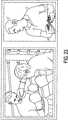
図22Bは、レースの続きであり、ウィンドウ2204’にあるプレーヤ1の透視図から分かるように、プレーヤ2は、車をスピンしている。ほぼリアルタイムに、プレーヤ1は、スピンしているプレーヤ2のアバターを見ることができ、このとき、プレーヤ2のアバターは、プレーヤ2の場所にあるカメラによってキャプチャされたプレーヤ2の実際の顔の表情の表現に基づいて修正される。ゲームプレイイベントを自動的に検知する実演として、ウィンドウ2202’に示すように、プレーヤ2のアバターの頭部を飛ぶ漫画の鳥が自動的に表示され、スピンアウト後のめまいを示す。めまいは、自動的に修正されたアバターの1つの特定の例であって、限定的になるように意図したものではない。現実世界のユーザによって引き起こされたり命令されたりするアクションに応答して、自動的に実行されるものを含む自動アバター修正の可能性は無限にある。別の実施形態において、プレーヤのアバター描写は、ゲームプレイイベントに応答して自動的に部分的に修正される。プレーヤのアバターの任意の自動修正が、現実世界のユーザのモニタされた反応と必ずししも完全に一致するわけではないことに留意されたい。 FIG. 22B is a continuation of the race, and
プレーヤ2のアバターは、ウィンドウ2202’に示されているように、イライラしてコントローラを掴みながら手を上げている。ビデオカメラは、ユーザのビデオをキャプチャするために使用されえ、さまざまなプログラムおよびプロセッサが、キャプチャされたビデオ内のユーザの動きを解析し検出するために使用されうる。ユーザの検出された動きは、第1のユーザのアバター描写にマッピングされ、ほぼリアルタイムに第2のユーザに表示されうる。ウィンドウ2208’に見られるように、プレーヤ1のアバターは、プレーヤ1がスピンアウトしたのを見た反応として目を見開いている。上記に挙げた修正された反応は、限定的であるように意図されたものではなく、アバターは、現実世界のユーザの動き、顔の反応、または音として聞こえる反応の変化を含むように修正されうることに留意されたい。一実施形態において、カメラおよびそれに関連するソフトウェアは、顔の表情、頭部の動き、および手の動きの変化に関して現実世界のユーザをモニタし、ほぼリアルタイムに現実世界のユーザのアバター描写を継続的に更新するように使用されうる。 The avatar of the
ユーザからの音として聞こえる反応は、マイクロホンを用いてキャプチャされうる。ハードウェアとソフトウェアとの組み合わせが、キャプチャされた音として聞こえる反応にある言葉を検出するために使用されうる。次に、検出された言葉は、選択された言葉がゲームプレイ中にプレーヤ間で伝達されるようにフィルタリングされうる。一実施形態において、検出されたフィルタリングされた言葉は、プレーヤのアバターと関連付けられたテキストバブルを用いて、原文のまま伝達されうる。別の実施形態において、検出されフィルタリングされた言葉は、第2のプレーヤの対話型ゲームセットアップと関連付けられたスピーカを介して聞こえるように伝えられる。さらなる別の実施形態において、検出されフィルタリングされた言葉は、聞こえるように原文のまま伝達される。一実施形態において、検出された言葉は、特定のゲームの娯楽ソフトウェア格付け委員会(ESRB)の格付けに基づいて、特定の言葉を含んだり排除したりするようにフィルタリングされうる。他の実施形態において、親が言葉のフィルタレベルを設定できる。 Reactions heard as sounds from the user can be captured using a microphone. A combination of hardware and software can be used to detect words in response that are heard as captured sound. The detected words can then be filtered so that the selected words are communicated between players during game play. In one embodiment, the detected filtered words may be communicated textually using a text bubble associated with the player's avatar. In another embodiment, the detected and filtered words are communicated to be heard via a speaker associated with the second player's interactive game setup. In yet another embodiment, the detected and filtered words are communicated in the original text so that they can be heard. In one embodiment, detected words may be filtered to include or exclude certain words based on a particular game entertainment software rating committee (ESRB) rating. In other embodiments, a parent can set a filter level for words.
図22Cは、アバターに感情的特徴を与えうる別の例を示す。プレーヤ1は、ウィンドウ2204”のプレーヤ1の前の道路には何もない状態から分かるように、スピンアウトしたプレーヤ2を追い越している。ウィンドウ2202”は、プレーヤ2のアバターを示し、ウィンドウ2208”は、プレーヤ2を追い越したことの感情的応答として、頭を振って体を動かすプレーヤ1のアバターを示す。ウィンドウ2210”は、プレーヤ2の前にあるプレーヤ1の車を示す。 FIG. 22C shows another example that may provide emotional characteristics to the avatar.
図23は、ボクシングシミュレーション中の対戦相手の反応をアバターウィンドウに示す。この例において、図示したゲームスクリーンは、アバターウィンドウが、パンチを受けるプレーヤの顔の表情の反応を示しているため、パンチを放った側のプレーヤの斜視図のものである。 FIG. 23 shows the reaction of the opponent during the boxing simulation in the avatar window. In this example, the illustrated game screen is a perspective view of the player on the punching side, since the avatar window shows the reaction of the facial expression of the player receiving the punch.
図24は、ボクシングシミュレーション中の対戦相手の反応をアバターウィンドウに示す。この例において、図示してゲームスクリーンは、アバターウィンドウが、パンチを放ったプレーヤの威嚇する反応を示しているため、パンチを受ける側のプレーヤの斜視図のものである。 FIG. 24 shows the reaction of the opponent during the boxing simulation in the avatar window. In this example, the game screen shown is a perspective view of the player receiving the punch because the avatar window shows the threatening reaction of the player who has punched.
図25は、ロールプレイングゲーム中のチームメンバーの反応をアバターウィンドウに示す。この例において、図示したゲームスクリーンは、アバターウィンドウが、宝物箱を開けるプレーヤの嬉しそうな反応を示すため、開きつつある宝物箱を見つめるプレーヤの斜視図のものである。 FIG. 25 shows the reaction of team members during the role playing game in the avatar window. In this example, the illustrated game screen is from a perspective view of a player looking at the treasure box being opened because the avatar window shows the joyful reaction of the player opening the treasure box.
図26は、運転シミュレーション中のプレーヤの反応をアバターウィンドウに示す。この例において、図示したゲームスクリーンは、第2の場所にいるプレーヤの斜視図のものであり、アバターウィンドウは、ゲームスクリーンに見える飛行車を運転するプレーヤの驚いた顔の表情を反映している。 FIG. 26 shows the reaction of the player during the driving simulation in the avatar window. In this example, the game screen shown is from a perspective view of the player at the second location, and the avatar window reflects the surprised facial expression of the player driving the flying car visible on the game screen. .
図27は、ゴルフシミュレーション中の対戦相手の反応をアバターウィンドウに示す。この例において、図示したゲームスクリーンは、パッティング中のプレーヤの斜視図のものであり、アバターウィンドウは、パッティングするプレーヤを見る対戦相手が神経質になっている状態を示す図22A〜図27に挙げた例は、ゲームプレイ中にコンピュータ生成されたアバターの感情的特徴の応用の可能性を示すように意図されたものである。応用の可能性は多くあり、前述した例は、例示的なものであって限定を意図したものではない。 FIG. 27 shows the reaction of the opponent during the golf simulation in the avatar window. In this example, the game screen shown is that of a perspective view of the player being put, and the avatar window is shown in FIGS. An example is intended to show the potential application of emotional features of computer generated avatars during game play. There are many potential applications, and the examples described above are illustrative and not intended to be limiting.
図28は、本発明の一実施形態によるアバター制御システムを実施するためのコントローラと互換性のあるものであってもよいコンソールである、ソニー(登録商標)プレイステーション3(登録商標)のエンタテインメント機器のシステムアーキテクチャ全体を略図的に示す。システムユニット2800が設けられ、システムユニット2800には、さまざまな周辺デバイスが接続される。システムユニット2800は、セルプロセッサ2828と、ランバス(登録商標)ダイナミックランダムアクセスメモリ(XDRAM)ユニット2826と、専用ビデオランダムアクセスメモリ(VRAM)ユニット2832を有するリアリティシンセサイザグラフィックユニット2830と、I/Oブリッジ2834とを含む。また、システムユニット2800は、ディスク2840aを読み取るためのブルーレイ(登録商標)ディスクBD−ROM(登録商標)光ディスクリーダ2840と、I/Oブリッジ2834を介してアクセス可能なリムーバブルスロットインハードディスクドライブ(HDD)2836とを含む。任意に、システムユニット2800は、コンパクトフラッシュメモリカード、メモリスティック(登録商標)メモリカードなどを読み取るためのメモリカードリーダ2838をさらに含み、メモリカードリーダ2838は、I/Oブリッジ2834を介して同様にアクセス可能である。 FIG. 28 is an illustration of an entertainment device of
I/Oブリッジ2834はまた、6つのユニバーサルシリアルバス(USB)2.0ポート2824と、ギガビットイーサネットポート2822と、IEEE802.11b/gワイヤレスネットワーク(ワイファイ)ポート2820と、最高7つのブルートゥース接続の支持可能であるブルートゥース(登録商標)ワイヤレスリンクポート2818とに接続される。 The I /
動作中、I/Oブリッジ2834は、1つ以上のゲームコントローラ2802からのデータを含む、すべてのワイヤレス、USB、およびイーサネットデータを取り扱う。例えば、ユーザがゲームをしているとき、I/Oブリッジ2834は、ブルートゥースリンクを介してゲームコントローラ2802からデータを受信し、それに従い、ゲームの現在の状態を更新するセルプロセッサ2828にデータを送る。 In operation, the I /
ワイヤレス、USB、およびイーサネットポートはまた、リモートコントロール2804、キーボード2806、マウス2808、ソニープレイステーションポータブル(登録商標)エンタテインメント機器などのポータブルエンタテインメント機器2810と、アイトーイ(Eye Toy)(登録商標)ビデオカメラ2812などのビデオカメラと、マイクロホンヘッドセット2814などのゲームコントローラ2802に加えて他の周辺機器に接続を与える。したがって、このような周辺機器は、原則的に、システムユニット2800にワイヤレス接続され、例えば、ポータブルエンタテインメント機器2810は、ワイファイアドホック接続を介して通信してもよく、マイクロホンヘッドセット2814は、ブルートゥースリンクを介して通信してもよい。 Wireless, USB, and Ethernet ports also include a
これらのインタフェースの提供は、プレイステーション3デバイスが、ディジタルビデオレコーダ(DVR)、セットトップボックス、ディジタルカメラ、ポータブルメディアプレーヤ、IP電話を利用した音声通信機器、モバイル電話、プリンタ、およびスキャナなどの他の周辺機器とも互換性の可能性があるということを意味する。 The provision of these interfaces allows
さらに、プレイステーション(登録商標)またはプレイステーション2(登録商標)デバイスによって使用される種類のメモリカード2848を読み取ることが可能な従来のメモリカードリーダ2816が、USBポート2824を介してシステムユニットに接続されてもよい。 In addition, a conventional memory card reader 2816 capable of reading the type of memory card 2848 used by the PlayStation® or
この実施形態において、ゲームコントローラ2802は、ブルートゥースリンクを介してシステムユニット2800とワイヤレス通信するように動作可能である。しかしながら、ゲームコントローラ2802は、その代わりに、USBポートに接続され、この接続により電力を得て、ゲームコントローラ2802のバッテリーが充電される。1つ以上のアナログジョイスティックおよび従来の制御ボタンの他にも、ゲームコントローラは、各軸の並進および回転に対応する6自由度の運動に感応性がある。結果的に、ゲームコントローラのユーザによるジェスチャおよび動きは、従来のボタンまたはジョイスティック命令に加え、またはその代わりに、ゲームへの入力として変換されてもよい。任意に、プレイステーション(登録商標)ポータブルデバイスなどの他のワイヤレス使用可能周辺機器が、コントローラとして使用されてもよい。プレイステーション(登録商標)ポータブルデバイスの場合、デバイスのスクリーン上に、追加のゲームまたはコントロール情報(例えば、制御命令や命の数)が提供されてもよい。また、ダンスマット(図示せず)、ライトガン(図示せず)、ハンドルとペダル(図示せず)、または迅速な応答のクイズゲーム(図示せず)用の1つまたは複数の大きなボタンなどの特注コントローラなどの他の別の補助的な制御デバイスが使用されてもよい。 In this embodiment,
リモートコントロール2804はまた、ブルートゥースリンクを介してシステムユニット2800とワイヤレス通信するように動作可能である。リモートコントロール2804は、ブルーレイ(登録商標)ディスクBD−ROMリーダ2840を動作し、ディスクコンテンツをナビゲーションするのに適したコントロールを含む。 The
ブルーレイ(登録商標)ディスクBD−ROMリーダ2840は、従来の記録済みおよび追記型のCDと、いわゆるスーパーオーディオCDに加え、プレイステーションおよびプレイステーション2デバイスと互換性のあるCD−ROMを読み取るように動作可能である。リーダ2840はまた、従来の記録済みおよび追記型DVDに加え、プレイステーション2およびプレイステーション3デバイスと互換性のあるDVD−ROMを読み取るように動作可能である。リーダ2840は、プレイステーション3デバイスとともに、従来の記録済みおよび追記型のブルーレイディスクと互換性のあるBD−ROMを読み取るようにさらに動作可能である。 Blu-ray (R) disc BD-
システムユニット2800は、リアリティシンセサイザグラフィックユニット2830を介して、オーディオおよびビデオコネクタを通して、ディスプレイ2814および1つ以上のラウドスピーカ2846を有するモニタまたはテレビ受像機セットなどのディスプレイおよび音声出力デバイス284に、プレイステーション3デバイスによって生成または復号化されたオーディオおよびビデオを供給するように動作可能である。オーディオコネクタ2850は、従来のアナログおよびディジタル出力を含んでもよく、ビデオコネクタ2852は、コンポーネントビデオ、Sビデオ、複合ビデオ、および1つ以上の高解像度マルチメディアインタフェース(HDMI)出力を種々に含んでもよい。結果的に、ビデオ出力は、PALまたはNTSCなどの形式のものであっても、720p、1080i、または1080p高解像度のものであってもよい。
オーディオ処理(生成、復号など)が、セルプロセッサ1128によって実行される。プレイステーション3デバイスのオペレーティングシステムは、ドルビー(登録商標)5.1サラウンドサウンド、ドルビー(登録商標)シアターサラウンド(DTS)、およびブルーレイ(登録商標)ディスクからの7.1サラウンドサウンドの復号をサポートする。 Audio processing (generation, decoding, etc.) is performed by the cell processor 1128. The
本発明の実施形態において、ビデオカメラ2812は、単一の電荷結合素子(CCD)と、LEDインジケータと、ハードウェアベースの実時間データ圧縮および符号化装置とを含み、この装置では、システムユニット2800によって復号化するためのイントラ画像ベースのMPEG(動画専門家グループ)標準などの適切な形式で圧縮ビデオデータ送信されてもよい。カメラLEDインジケータは、例えば、劣悪な照明条件を表すために、システムユニット2800からの適切な制御データに応答して照明するように配設される。ビデオカメラ2812の実施形態は、USB、ブルートゥース、またはワイファイ通信ポートを介して、システムユニット2800に種々に接続されてもよい。ビデオカメラの実施形態は、1つ以上の関連するマイクロホンを含んでもよく、オーディオデータを送信可能であってもよい。ビデオカメラの実施形態において、CCDの解像度は、高解像度ビデオキャプチャに適したものであってもよい。使用中、ビデオカメラによってキャプチャされる画像は、例えば、ゲーム内に取り込まれてもよく、またはゲーム制御入力として解釈されてもよい。 In an embodiment of the present invention,
一般に、システムユニット2800の通信ポートの1つを介して、ビデオカメラやリモートコントロールなどの周辺デバイスとのデータ通信をうまく行うために、デバイスドライバなどの適切なソフトウェアを提供する必要がある。デバイスドライバ技術は周知のものであるため、本明細書に記載する実施形態においてデバイスドライバまたは同様のソフトウェアインタフェースが要求されるであろうことを当業者が認識しているであろうことを述べるだけで、本明細書においては詳細に記載しない。 In general, in order to successfully perform data communication with a peripheral device such as a video camera or remote control via one of the communication ports of the
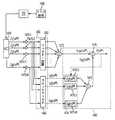
以下、図29を参照すると、セルプロセッサ2828は、4つの基本的なコンポーネント、すなわち、メモリコントローラ2960およびデュアルバスインタフェースコントローラ2970A、Bを含む外部入出力構造と、パワー処理エレメント2950と呼ばれるメインプロセッサと、相乗的処理エレメント(SPE)2910A〜Hと呼ばれる8つのコプロセッサと、エレメントインターコネクトバス2980よ呼ばれる上記コンポーネントを接続する巡回データバスとを含むアーキテクチャを有する。セルプロセッサの総浮動小数点性能は、プレイステーション2デバイスのエモーションエンジンの6.2GFLOPSと比較すると、218GFLOPSである。 Referring now to FIG. 29,
パワー処理エレメント(PPE)2950は、3.2GHzの内部クロックで動作し、二方向同時マルチスレッディングパワー970に対応したパワーPCコア(PPU)2955に基づいたものである。PPE2950は、512kBのレベル2(L2)キャッシュと、32kBのレベル1(L1)キャッシュとを含む。PPE2950は、3.2GHzで25.6GFLOPSに変換するクロックサイクル当たり8つの単位置演算が可能である。PPE2950の主な役割は、計算作業量のほとんどを取り扱う相乗的処理エレメント2910A〜Hのコントローラとして作用することである。動作中、PPE2950は、相乗的処理エレメント2910A〜Hのジョブをスケジューリングし、その進行をモニタしながら、ジョブキューを維持する。結果的に、各相乗的処理エレメント2910A〜Hは、ジョブをフェッチし、実行し、PPE2950と同期させる役割のカーネルを実行する。 The power processing element (PPE) 2950 is based on a power PC core (PPU) 2955 that operates with an internal clock of 3.2 GHz and supports bidirectional multi-threading power 970. The
各相乗的処理エレメント(SPE)2910A〜Hは、それぞれ、相乗的処理ユニット(SPU)2920A〜Hと、ダイナミックメモリアクセスコントローラ(DMAC)2942A〜Hをそれぞれ含むそれぞれのメモリフローコントローラ(MFC)2940A〜Hと、メモリ管理ユニット(MMU)2944A〜Hと、バスインタフェース(図示せず)とを含む。各SPU2920A〜Hは、3.2GHzのクロック周波数のRISCプロセッサであり、原則的に、4GBまで拡張可能な256kBのローカルRAM2930A〜Hを含む。各SPEは、理論値25.6GFLOPSの単精度性能を与える。SPUが、単一のクロックサイクルにおいて4つの単精度浮動小数点要素、4つの32ビット数値、8つの16ビット整数、または16個の8ビット整数で動作しうる。同じクロックサイクルにおいて、SPUは、メモリ動作も実行しうる。SPU2920A〜Hは、システムメモリXDRAM2826に直接アクセスせず、SPU2920A〜Hによって形成された64ビットは、MFC2940A〜Hに送られ、MFC2940A〜Hは、そのDMAコントローラ2942A〜Hに命令して、エレメントインターコネクトバス2980およびメモリコントローラ2960を介してメモリにアクセスする。 Each synergistic processing element (SPE) 2910A-H includes a respective synergistic processing unit (SPU) 2920A-H and a respective memory flow controller (MFC) 2940A-H that includes a dynamic memory access controller (DMAC) 2942A-H, respectively. H, memory management units (MMU) 2944A-H, and a bus interface (not shown). Each
エレメントインターコネクトバス(EIB)2980は、セルプロセッサ282の内部にある論理的に巡回型の通信バスであり、この通信バスは、上記プロセッサエレメント、すなわち、PPE2950、メモリコントローラ2960、デュアルバスインタフェース2970A、B、および8つのSPE1210A〜Hの全部で12の関与エレメントを接続する。関与エレメントは、1クロックサイクル当たり8バイトのレートでバスに同時に読み書きされうる。前述したように、各SPE2910A〜Hは、より長い読み取りまたは書き込みシーケンスをスケジューリングするためのDMAC2942A〜Hを含む。EIBは、4つのチャネルを含み、2つずつがそれぞれ、時計回りおよび反時計回りの方向である。結果的に、12の関与エレメントに対して、任意の2つの関与エレメントの間の最も長い段階的なデータフローのステップ数は、適切な方向において6段階である。したがって、12スロットの理論ピーク瞬時EIB帯域幅は、関与エレメント間の調停によってすべて利用される場合、クロック当たり96Bである。これは、3.2GHzのクロックレートで307.2GB/s(1秒当たりのギガバイト)の理論ピーク帯域幅に等しい。 The element interconnect bus (EIB) 2980 is a logically cyclic communication bus inside the cell processor 282, and this communication bus includes the processor elements, that is, the
メモリコントローラ2960は、ランバス(Rambus)社によって開発されたXDRAMインタフェース2962を含む。メモリコントローラは、25.6GB/sの理論ピーク帯域幅をもつランバスXDRAM2826と連動する。
デュアルバスインタフェース2970A、Bは、ランバス社製のFlexIO(登録商標)システムインタフェース2972A、Bを含む。インタフェースは、下り5経路および上り7経路を有する、それぞれが8ビット幅の12チャネルに体系化される。これにより、コントローラ2972Aを介したセルプロセッサおよびI/Oブリッジ2834と、およびコントローラ2972Bを介してリアリティシミュレータグラフィックユニット2830との間に、62.4GB/s(下り36.4GB/s、上り26GB/s)の理論ピーク帯域幅が得られる。 The
セルプロセッサ2828によってリアリティシミュレータグラフィックユニット2830に送信されるデータは、典型的に、頂点を描き、テクスチャを多角形に適用し、照明条件を明示するなどの一連の命令である表示リストを含む。 The data sent by the
実施形態は、現実世界のユーザをさらに良好に識別し、アバターまたはシーンの活動を指示するために、深度データをキャプチャすることを含む。オブジェクトは、人が保持しているものであっても、人の手であってもよい。本明細書において、「深度カメラ」および「3次元カメラ」という用語は、2次元ピクセル情報の他にも、距離または深度情報を獲得可能な任意のカメラをさす。例えば、深度カメラが、距離情報を得るために、制御された赤外線発光体を利用しうる。別の例示的な深度カメラは、2つの標準的なカメラを用いて距離情報を三角測量するステレオカメラペアでありうる。同様に、「深度検知デバイス」という用語は、2次元ピクセル情報の他にも、距離情報を獲得可能な任意のタイプのデバイスをさす。 Embodiments include capturing depth data to better identify real world users and direct avatar or scene activity. The object may be held by a person or a hand of a person. In this specification, the terms “depth camera” and “3D camera” refer to any camera capable of acquiring distance or depth information in addition to 2D pixel information. For example, a depth camera can utilize a controlled infrared emitter to obtain distance information. Another exemplary depth camera can be a stereo camera pair that uses two standard cameras to triangulate distance information. Similarly, the term “depth sensing device” refers to any type of device that can acquire distance information in addition to two-dimensional pixel information.
3次元画像の最近の進歩により、リアルタイムの対話型コンピュータアニメーションの可能性が新たに増えてきた。特に、新しい「深度カメラ」では、通常の2次元ビデオ画像の他にも、第3次元をキャプチャしマッピングすることができる。新しい深度データを用いて、本発明の実施形態により、他のオブジェクトの後方を含む、ビデオシーン内のさまざまな位置にリアルタイムでコンピュータ生成オブジェクトを配置できる。 Recent advances in 3D images have increased the possibility of real-time interactive computer animation. In particular, the new “depth camera” can capture and map the third dimension in addition to the normal two-dimensional video image. With new depth data, embodiments of the present invention can place computer generated objects in real time at various locations in the video scene, including behind other objects.
さらに、本発明の実施形態により、ユーザにリアルタイムの対話型ゲーム体験が提供される。例えば、ユーザは、さまざまなコンピュータ生成オブジェクトとリアルタイムに対話できる。さらに、ビデオシーンは、ユーザのゲーム体験を高めるために、リアルタイムで変更されうる。例えば、コンピュータ生成のコスチュームを、ユーザの衣服の上にはめ込むことができ、コンピュータ生成の光源を、ビデオシーン内の仮想投影を映し出すために利用されうる。このようにして、本発明の実施形態および深度カメラを用いて、ユーザが、自分のリビングルームで対話型ゲーム環境を体験できる。通常のカメラと同様に、深度カメラが、ビデオ画像を含む複数のピクセルの2次元データをキャプチャする。これらの値は、ピクセルに対するカラー値であり、一般に、各ピクセルに対して赤、緑、および青の(RGB)値である。このようにして、カメラがキャプチャしたオブジェクトは、モニタ上に2次元オブジェクトとして現れる。 Furthermore, embodiments of the present invention provide users with a real-time interactive gaming experience. For example, a user can interact with various computer-generated objects in real time. Furthermore, the video scene can be changed in real time to enhance the user's gaming experience. For example, a computer-generated costume can be fitted over the user's clothing, and a computer-generated light source can be utilized to project a virtual projection in the video scene. In this way, using the embodiment of the present invention and the depth camera, a user can experience an interactive game environment in his / her living room. Similar to a normal camera, a depth camera captures two-dimensional data of a plurality of pixels including a video image. These values are the color values for the pixels, typically red, green, and blue (RGB) values for each pixel. In this way, the object captured by the camera appears as a two-dimensional object on the monitor.
本発明の実施形態はまた、分散型の画像処理構造についても検討する。例えば、本発明は、CPUまたはCPUとその他のエレメントなど、1つまたは2つの場所で行われている、キャプチャされた画像およびディスプレイ画像処理に限定されるものではない。例えば、入力画像処理は、処理を実行しうる関連のCPU、プロセッサ、またはデバイスにおいて容易に行うことができるものであり、原則的に全ての画像処理は、相互接続システムを通じて分散されうる。このように、本発明は、いずれの具体的な画像処理ハードウェア回路および/またはソフトウェアに限定されるものではない。本明細書に記載する実施形態もまた、一般のハードウェア回路および/またはソフトウェアの任意の特定の組み合わせにも、処理コンポーネントによって実行される命令に対する任意の特定のソースにも限定されるものではない。 Embodiments of the present invention also consider distributed image processing structures. For example, the present invention is not limited to captured image and display image processing performed in one or two locations, such as a CPU or CPU and other elements. For example, input image processing can be easily performed in an associated CPU, processor, or device that can perform the processing, and in principle all image processing can be distributed throughout the interconnect system. Thus, the present invention is not limited to any specific image processing hardware circuit and / or software. The embodiments described herein are also not limited to any particular combination of general hardware circuitry and / or software, nor to any particular source for instructions executed by a processing component. .
上記の実施形態を考慮に入れて、本発明が、コンピュータシステムに格納されたデータを使用する、さまざまなコンピュータ実装動作を用いてもよいことを理解されたい。これらの動作には、物理量の物理的な操作を必要とする動作が含まれる。この物理量は、通常、格納、転送、結合、比較、または他の操作が可能な電気信号または磁気信号の形を取るが、必ずしもこれらに限定されない。さらに、実行される操作は、多くの場合、生成、識別、判断、または比較などの用語で参照される。 In view of the above embodiments, it should be understood that the present invention may employ a variety of computer-implemented operations that use data stored in a computer system. These operations include operations that require physical manipulation of physical quantities. This physical quantity typically takes the form of, but not necessarily limited to, an electrical or magnetic signal that can be stored, transferred, combined, compared, or otherwise manipulated. Furthermore, the operations performed are often referred to in terms such as generation, identification, judgment, or comparison.
本発明は、本明細書において提示されるように用いられてもよく、または、他のユーザ入力機構と組み合わせて、さらには、音声の角度方向をトラッキングする機構および/または能動的または受動的にオブジェクトの位置をトラッキングする機構、機械視覚を用いた機構、それらの組み合わせとともに用いられてもよく、トラッキングされているオブジェクトは、システムへのフィードバックを操作する補助コントロールやボタンを含んでもよく、このようなフィードバックは、光源からの光放出、音声歪み手段、または他の適切な送信機および変調器とともに、送信や変調に影響を与え、状態を符号化し、および/またはトラッキングされているデバイスとの間で命令を送信してもよいボタン、圧力パッドなどを含んでもよいが、これらに限定されるものではない。 The present invention may be used as presented herein, or in combination with other user input mechanisms, as well as mechanisms for tracking the angular direction of speech and / or active or passive It may be used in conjunction with a mechanism for tracking the position of an object, a mechanism using machine vision, or a combination thereof, and the object being tracked may include auxiliary controls and buttons to manipulate feedback to the system, such as Feedback, along with light emission from the light source, sound distortion means, or other suitable transmitters and modulators, affects the transmission and modulation, and encodes and / or tracks with the device being tracked May include buttons, pressure pads, etc. The present invention is not limited.
本発明は、ゲームコンソール、ゲームコンピュータまたはコンピュータデバイス、ハンドヘルドデバイス、マイクロプロセッサシステム、マイクロプロセッサベースまたはプログラマブル民生電子機器、ミニコンピュータ、メインフレームコンピュータなどを含む他のコンピュータシステム構成で実施されてもよい。また、本発明は、分散コンピュータ環境で実施され、このような環境では、ネットワークを介してリンクされる遠隔処理デバイスによってタスクが実行される。例えば、オンラインゲームシステムおよびソフトウェアが使用されてもよい。 The invention may be practiced with other computer system configurations including game consoles, game computers or computer devices, handheld devices, microprocessor systems, microprocessor-based or programmable consumer electronics, minicomputers, mainframe computers and the like. The invention is also practiced in distributed computing environments where tasks are performed by remote processing devices that are linked through a network. For example, online game systems and software may be used.
上記の実施形態を考慮に入れて、本発明が、コンピュータシステムに格納されたデータを使用する、さまざまなコンピュータ実装動作を使用してもよいことを理解されたい。これらの動作は、物理量の物理的な操作を要するものである。この物理量は、通常、格納、転送、結合、比較、または他の操作が可能な電気信号または磁気信号の形を取るが、必ずしもこれらに限定されない。さらに、実行される操作は、多くの場合、生成、識別、判断、または比較などの用語で参照される。 In view of the above embodiments, it should be understood that the present invention may use a variety of computer-implemented operations that use data stored in a computer system. These operations require physical manipulation of physical quantities. This physical quantity typically takes the form of, but not necessarily limited to, an electrical or magnetic signal that can be stored, transferred, combined, compared, or otherwise manipulated. Furthermore, the operations performed are often referred to in terms such as generation, identification, judgment, or comparison.
本発明の一部をなす本明細書に記載する動作はいずれも、有用な機械動作である。本発明は、これらの動作を実行するデバイスまたは装置にも関する。この装置は、上述したキャリアネットワークなど、所望の目的のために特別に作製されたものであってもよく、または、コンピュータに格納されたコンピュータプログラムによって選択的に作動または構成される汎用コンピュータであってもよい。特に、各種の汎用の機械が、本明細書の教示に従って記述したコンピュータプログラムとともに使用され、または、所望の動作を実行するためにさらに特化した装置を作製するほうが利便性が高いこともある。 Any of the operations described herein that form part of the present invention are useful machine operations. The present invention also relates to a device or apparatus for performing these operations. This device may be specially made for the desired purpose, such as the carrier network described above, or it may be a general purpose computer selectively activated or configured by a computer program stored in the computer. May be. In particular, it may be more convenient to use a variety of general purpose machines with a computer program described in accordance with the teachings herein, or to create a more specialized device for performing a desired operation.
本発明はまた、コンピュータ可読媒体上にコンピュータ可読コードとして実現されることもできる。コンピュータ可読媒体は、データを格納しうる任意のデータストレージデバイスであってもよく、このデータは、コンピュータシステムによって読み取られうる。コンピュータ可読媒体の例は、ハードドライブ、ネットワーク接続ストレージ(NAS)、読み出し専用メモリ、ランダムアクセスメモリ、フラッシュベースメモリ、CD−ROM,CD−R、CD−RW、DVD、磁気テープ、および他の光学および非光学データストレージデバイスを含む。コンピュータ可読媒体は、コンピュータ可読コードが分散式で格納され、実行されてもよいように、ネットワークに接続されたコンピュータシステム上に分散されうる。 The invention can also be embodied as computer readable code on a computer readable medium. The computer readable medium may be any data storage device that can store data, which can be read by a computer system. Examples of computer readable media are hard drives, network attached storage (NAS), read only memory, random access memory, flash based memory, CD-ROM, CD-R, CD-RW, DVD, magnetic tape, and other optical. And non-optical data storage devices. The computer readable medium may be distributed over a networked computer system so that the computer readable code may be stored and executed in a distributed fashion.
明確に理解できるようにするために、前述の発明をある程度詳細に記載してきたが、添付の特許請求の範囲内で特定の変更と修正がされるのは明らかであろう。したがって、本発明の実施形態は、例示的なものであり限定的なものではないと考慮されるべきであり、本発明は、本明細書で述べた詳細に限定されることはなく、添付の特許請求の範囲およびその等価物の範囲で修正されてもよい。 Although the foregoing invention has been described in some detail for purposes of clarity of understanding, it will be apparent that certain changes and modifications may be practiced within the scope of the appended claims. Accordingly, the embodiments of the present invention should be considered as illustrative and not restrictive, and the present invention is not limited to the details described herein, Modifications may be made within the scope of the claims and their equivalents.
Claims (14)
Translated fromJapanese前記コンピュータが、
ゲームプレイを実行するステップと、
前記第1および第2のユーザの一方または両方の反応をモニタするステップと、
ゲームプレイのディスプレイエリアの側部に沿って、前記第1および第2のユーザの一方または両方のアバター描写を表示するステップと、
ゲームプレイの実行中、前記第1および第2のユーザのモニタされた反応に応答して、前記第1および第2のユーザの一方または両方のアバター描写の反応を修正するステップと、を実行する、方法。Modify an avatar in response to a user response to a game play event, the avatarrepresenting one or bothof the first user and the second user andcustomizable to represent the user himself A computer-implemented method, wherein the gameplay event is anicon or graphic and results from execution of a computer program and user input to a computer system that executes at least a portion of the computer program. ,
The computer is
Performing game play; and
Monitoring the reaction of one or both of the first and second users;
Displaying an avatar depiction of one or both of the first and second users along a side of a display area of game play;
Modifying the avatar depiction response of one or both of the first and second users in response to the monitored response of the first and second users during game play. ,Method.
前記第1のユーザのビデオをキャプチャするステップと、
前記第1のユーザの動きを検出するステップと、
前記第1のユーザの検出された動きを前記第1のユーザのアバター描写にマッピングするステップと、
前記第1または第2のユーザのいずれかのコンピュータシステムに接続されたディスプレイ画面上に前記アバター描写を表示するステップとを含む、請求項1に記載の方法。Monitoring the reaction of one or both of the first and second users;
Capturing the video of the first user;
Detecting the movement of the first user;
Mapping the detected motion of the first user to an avatar depiction of the first user;
And displaying the avatar depiction on a display screen connected to a computer system of either the first or second user.
前記第1のユーザおよび前記第2のユーザの音声をキャプチャするステップと、
前記キャプチャされた音声から得られた言葉を検出するステップと、
前記言葉のうちの選択された言葉が、ゲームプレイ中に前記第1のユーザと第2のユーザとの間で通信されるように、前記検出された言葉をフィルタリングするステップとを含む、請求項1に記載の方法。Monitoring the reaction of one or both of the first and second users;
Capturing audio of the first user and the second user;
Detecting words obtained from the captured speech;
Filtering the detected words such that a selected word of the words is communicated between the first user and a second user during game play. The method according to 1.
顔の反応、頭の動き、および手の動きの1つを、ゲームプレイのディスプレイエリアの側部に沿って表示するステップと、
前記第1のユーザと前記第2のユーザとの間でゲームプレイ反応を通信するように、リアルタイムに前記アバター描写を継続的に更新するステップとを含む、請求項1に記載の方法。Modifying the response of the avatar depiction,
Displaying one of facial reactions, head movements, and hand movements along the sides of the display area of the gameplay;
The method of claim 1, comprising continuously updating the avatar depiction in real time to communicate game play responses between the first user and the second user.
前記コンピュータが、
ゲームプレイを実行するステップと、
前記第1および第2のユーザの一方または両方の反応をモニタするステップと、
ゲームプレイのディスプレイエリアの側部に沿って、前記第1および第2のユーザの一方または両方のアバター描写を表示するステップと、
ゲームプレイの実行中、前記第1および第2のユーザのモニタされた反応に応答して、前記第1および第2のユーザの一方または両方のアバター描写の反応を修正するステップと、を実行し、前記アバター描写が、ゲームプレイイベントに応答して自動的に少なくとも部分的に修正され、自動的に修正されたとき、前記アバター描写の修正が、前記第1のユーザまたは前記第2のユーザのモニタされた反応と異なるものである、方法。Modify an avatar in response to a user response to a game play event, the avatarrepresenting one or bothof the first user and the second user andcustomizable to represent the user himself A computer-implemented method, wherein the gameplay event is anicon or graphic and results from execution of a computer program and user input to a computer system that executes at least a portion of the computer program. ,
The computer is
Performing game play; and
Monitoring the reaction of one or both of the first and second users;
Displaying an avatar depiction of one or both of the first and second users along a side of a display area of game play;
Modifying the avatar depiction response of one or both of the first and second users in response to the monitored response of the first and second users during execution of game play; , When the avatar depiction is automatically and at least partially modified in response to a game play event and automatically modified, the modification of the avatar depiction is made by the first user or the second user. A method that is different from the monitored response.
(B)前記ゲームプレイがオンラインで実行され、前記第1および第2のユーザの各々のコンピュータシステムが、前記第1および第2のユーザのそれぞれのコンピュータシステムおよびインターネット接続上で接続されたネットワークコンピュータで実行されるコンピュータプログラムとのインタラクションを行い、または、
(C)前記第1および第2のユーザの一方または両方の反応をモニタするステップが、
前記第1または第2のユーザの一方のビデオをキャプチャするステップと、
前記第1または第2のユーザの動きを検出するステップと、
前記第1または第2のユーザの検出された動きを前記第1または第2のユーザのアバター描写にマッピングするステップと、
前記第1または第2のユーザのいずれかのコンピュータシステムに接続されたディスプレイ画面上に前記アバター描写を表示するステップとを含み、または、
(D)前記第1および第2のユーザの一方または両方の反応をモニタするステップが、
前記第1のユーザおよび前記第2のユーザの音声をキャプチャするステップと、
前記キャプチャされた音声から得られた言葉を検出するステップと、
前記言葉のうちの選択された言葉が、ゲームプレイ中に前記第1のユーザと第2のユーザとの間で通信されるように、前記検出された言葉をフィルタリングするステップとを含み、または、
(E)前記アバター描写の反応を修正するステップが、
顔の反応、頭の動き、および手の動きの1つを、ゲームプレイのディスプレイエリアの側部に沿って表示するステップと、
前記第1のユーザと前記第2のユーザとの間でゲームプレイ反応を通信するように、リアルタイムに前記アバター描写を継続的に更新するステップとを含む、請求項7に記載の方法。(A) the avatar description identifies at least one of a movement, a facial response, or a audible response of one or both of the first and second users by the displayed avatar description, or
(B) A network computer in which the game play is executed online, and the computer systems of the first and second users are connected to the computer systems of the first and second users and an Internet connection, respectively. Interact with computer programs executed in
(C) monitoring the reaction of one or both of the first and second users;
Capturing a video of one of the first or second users;
Detecting the movement of the first or second user;
Mapping the detected motion of the first or second user to an avatar depiction of the first or second user;
Displaying the avatar depiction on a display screen connected to a computer system of either the first or second user, or
(D) monitoring the reaction of one or both of the first and second users;
Capturing audio of the first user and the second user;
Detecting words obtained from the captured speech;
Filtering the detected words such that a selected word of the words is communicated between the first user and a second user during game play, or
(E) modifying the avatar depiction response,
Displaying one of facial reactions, head movements, and hand movements along the sides of the display area of the gameplay;
8. The method of claim 7, comprising continuously updating the avatar depiction in real time to communicate game play responses between the first user and the second user.
前記コンピュータが、
ゲームプレイ中に生じたアクションを識別するために、ゲームプレイイベントをモニタするステップと、
前記ゲームプレイアクションに対する応答を視覚的に伝えるために、ゲームプレイ中に生じる識別されたアクションに応答して、前記第1のユーザを表す前記アバターのグラフィック画像を修正するステップと、
前記第1のユーザを表す前記アバターの修正されたグラフィック画像を第2のユーザに表示するステップと、を実行し、
第1のユーザを表す前記修正されたアバターにより、前記第2のユーザが、前記第1のユーザに生じたゲームプレイアクションを知ることができる、方法。Automatically modifying the avatar in response to a game play event, wherein the avatar represents the firstuser and is an icon or graphic that can be customized to represent the user, the game play event being a computer A computer-implemented method that results from execution of a program and user input to a computer system that executes at least a portion of the computer program comprising:
The computer is
Monitoring game play events to identify actions that occurred during game play;
Modifying a graphic image of the avatar representing the first user in response to an identified action occurring during game play to visually convey a response to the game play action;
Displaying a modified graphic image of the avatar representing the first user to a second user;
The method, wherein the modified avatar representing the first user allows the second user to know the game play action that has occurred to the first user.
前記第1および第2のユーザの一方または両方の反応をモニタするステップと、
前記第1のユーザまたは前記第2のユーザの前記アバターの前記グラフィック画像を表示するステップと、
ゲームプレイの実行中、前記第1および第2のユーザのモニタされた反応に応答して、前記第1および第2のユーザの一方または両方のアバターの反応を修正するステップとをさらに含み、
前記第1または第2のユーザのいずれかのモニタされた反応に基づいて、前記アバターの反応を修正するステップが、ゲームプレイイベントに基づいて自動修正するステップに追加される、請求項9に記載の方法。A computer-implemented method that automatically modifies an avatar in response to a gameplay event,
Monitoring the reaction of one or both of the first and second users;
Displaying the graphic image of the avatar of the first user or the second user;
Modifying the avatar response of one or both of the first and second users in response to the monitored response of the first and second users during execution of game play;
10. The step of modifying the avatar's response based on the monitored response of either the first or second user is added to the step of automatically correcting based on a game play event. the method of.
Applications Claiming Priority (7)
| Application Number | Priority Date | Filing Date | Title |
|---|---|---|---|
| US74664006P | 2006-05-07 | 2006-05-07 | |
| US60/746,640 | 2006-05-07 | ||
| US74677706P | 2006-05-08 | 2006-05-08 | |
| US74677306P | 2006-05-08 | 2006-05-08 | |
| US60/746,773 | 2006-05-08 | ||
| US60/746,777 | 2006-05-08 | ||
| PCT/US2007/011141WO2007130691A2 (en) | 2006-05-07 | 2007-05-07 | Method for providing affective characteristics to computer generated avatar during gameplay |
Publications (2)
| Publication Number | Publication Date |
|---|---|
| JP2009536406A JP2009536406A (en) | 2009-10-08 |
| JP4921550B2true JP4921550B2 (en) | 2012-04-25 |
Family
ID=38668402
Family Applications (1)
| Application Number | Title | Priority Date | Filing Date |
|---|---|---|---|
| JP2009509822AActiveJP4921550B2 (en) | 2006-05-07 | 2007-05-07 | How to give emotional features to computer-generated avatars during gameplay |
Country Status (4)
| Country | Link |
|---|---|
| US (3) | US8601379B2 (en) |
| EP (2) | EP2194509A1 (en) |
| JP (1) | JP4921550B2 (en) |
| WO (2) | WO2007130693A2 (en) |
Families Citing this family (577)
| Publication number | Priority date | Publication date | Assignee | Title |
|---|---|---|---|---|
| JP2002073542A (en) | 2000-08-31 | 2002-03-12 | Sony Corp | Server use reservation method, reservation management device, and program storage medium |
| US8543390B2 (en)* | 2004-10-26 | 2013-09-24 | Qnx Software Systems Limited | Multi-channel periodic signal enhancement system |
| US8488023B2 (en)* | 2009-05-20 | 2013-07-16 | DigitalOptics Corporation Europe Limited | Identifying facial expressions in acquired digital images |
| US7459624B2 (en) | 2006-03-29 | 2008-12-02 | Harmonix Music Systems, Inc. | Game controller simulating a musical instrument |
| JP5330640B2 (en)* | 2006-05-09 | 2013-10-30 | 任天堂株式会社 | GAME PROGRAM, GAME DEVICE, GAME SYSTEM, AND GAME PROCESSING METHOD |
| US8384665B1 (en)* | 2006-07-14 | 2013-02-26 | Ailive, Inc. | Method and system for making a selection in 3D virtual environment |
| WO2008021091A2 (en)* | 2006-08-11 | 2008-02-21 | Packetvideo Corp. | 'system and method for delivering interactive audiovisual experiences to portable devices' |
| US20080066137A1 (en)* | 2006-08-25 | 2008-03-13 | Sbc Knowledge Ventures, Lp | System and method of displaying system content |
| US7966567B2 (en)* | 2007-07-12 | 2011-06-21 | Center'd Corp. | Character expression in a geo-spatial environment |
| JP2010520565A (en)* | 2007-03-02 | 2010-06-10 | オーガニック・モーション | System and method for tracking and recording a three-dimensional object |
| JP5149547B2 (en)* | 2007-06-07 | 2013-02-20 | 株式会社コナミデジタルエンタテインメント | GAME DEVICE, GAME DEVICE CONTROL METHOD, AND PROGRAM |
| EP2206539A1 (en) | 2007-06-14 | 2010-07-14 | Harmonix Music Systems, Inc. | Systems and methods for simulating a rock band experience |
| US8678896B2 (en) | 2007-06-14 | 2014-03-25 | Harmonix Music Systems, Inc. | Systems and methods for asynchronous band interaction in a rhythm action game |
| KR20090006371A (en)* | 2007-07-11 | 2009-01-15 | 야후! 인크. | Method and system for providing virtual co-existence to broadcast viewers or listeners in an online broadcasting system (virtual co-presence) |
| US8726194B2 (en)* | 2007-07-27 | 2014-05-13 | Qualcomm Incorporated | Item selection using enhanced control |
| WO2009020080A1 (en)* | 2007-08-03 | 2009-02-12 | Camelot Co., Ltd. | Game device, game program and game object operation method |
| WO2009029063A1 (en)* | 2007-08-24 | 2009-03-05 | Tc Digital Games Llc | System and methods for multi-platform trading card game |
| US8307035B2 (en)* | 2007-08-31 | 2012-11-06 | Lava Two, Llc | Virtual Aggregation Processor for incorporating reverse path feedback into content delivered on a forward path |
| WO2009029113A1 (en)* | 2007-08-31 | 2009-03-05 | Vulano Group, Inc. | Transaction management system in a multicast or broadcast wireless communication network |
| WO2009029107A1 (en)* | 2007-08-31 | 2009-03-05 | Vulano Group, Inc. | Gaming device for multi-player games |
| WO2009029110A1 (en)* | 2007-08-31 | 2009-03-05 | Vulano Group, Inc. | Forward path multi-media management system with end user feedback to distributed content sources |
| TWI372645B (en)* | 2007-10-17 | 2012-09-21 | Cywee Group Ltd | An electronic game controller with motion-sensing capability |
| US20090132361A1 (en)* | 2007-11-21 | 2009-05-21 | Microsoft Corporation | Consumable advertising in a virtual world |
| US8028094B2 (en)* | 2007-12-04 | 2011-09-27 | Vixs Systems, Inc. | USB video card and dongle device with video encoding and methods for use therewith |
| US7993190B2 (en)* | 2007-12-07 | 2011-08-09 | Disney Enterprises, Inc. | System and method for touch driven combat system |
| US20090157660A1 (en)* | 2007-12-13 | 2009-06-18 | Searete Llc, A Limited Liability Corporation Of The State Of Delaware | Methods and systems employing a cohort-linked avatar |
| US20090157813A1 (en)* | 2007-12-17 | 2009-06-18 | Searete Llc, A Limited Liability Corporation Of The State Of Delaware | Methods and systems for identifying an avatar-linked population cohort |
| US20090157625A1 (en)* | 2007-12-13 | 2009-06-18 | Searete Llc, A Limited Liability Corporation Of The State Of Delaware | Methods and systems for identifying an avatar-linked population cohort |
| US20090164302A1 (en)* | 2007-12-20 | 2009-06-25 | Searete Llc, A Limited Liability Corporation Of The State Of Delaware | Methods and systems for specifying a cohort-linked avatar attribute |
| US20090156955A1 (en)* | 2007-12-13 | 2009-06-18 | Searete Llc, A Limited Liability Corporation Of The State Of Delaware | Methods and systems for comparing media content |
| US8615479B2 (en)* | 2007-12-13 | 2013-12-24 | The Invention Science Fund I, Llc | Methods and systems for indicating behavior in a population cohort |
| US8195593B2 (en) | 2007-12-20 | 2012-06-05 | The Invention Science Fund I | Methods and systems for indicating behavior in a population cohort |
| US20090171164A1 (en)* | 2007-12-17 | 2009-07-02 | Jung Edward K Y | Methods and systems for identifying an avatar-linked population cohort |
| US8356004B2 (en)* | 2007-12-13 | 2013-01-15 | Searete Llc | Methods and systems for comparing media content |
| US20090157751A1 (en)* | 2007-12-13 | 2009-06-18 | Searete Llc, A Limited Liability Corporation Of The State Of Delaware | Methods and systems for specifying an avatar |
| US9211077B2 (en)* | 2007-12-13 | 2015-12-15 | The Invention Science Fund I, Llc | Methods and systems for specifying an avatar |
| US8069125B2 (en)* | 2007-12-13 | 2011-11-29 | The Invention Science Fund I | Methods and systems for comparing media content |
| US20090164458A1 (en)* | 2007-12-20 | 2009-06-25 | Searete Llc, A Limited Liability Corporation Of The State Of Delaware | Methods and systems employing a cohort-linked avatar |
| US20090157481A1 (en)* | 2007-12-13 | 2009-06-18 | Searete Llc, A Limited Liability Corporation Of The State Of Delaware | Methods and systems for specifying a cohort-linked avatar attribute |
| US20090164503A1 (en)* | 2007-12-20 | 2009-06-25 | Searete Llc, A Limited Liability Corporation Of The State Of Delaware | Methods and systems for specifying a media content-linked population cohort |
| US8150796B2 (en)* | 2007-12-20 | 2012-04-03 | The Invention Science Fund I | Methods and systems for inducing behavior in a population cohort |
| US9418368B2 (en)* | 2007-12-20 | 2016-08-16 | Invention Science Fund I, Llc | Methods and systems for determining interest in a cohort-linked avatar |
| US20090164131A1 (en)* | 2007-12-20 | 2009-06-25 | Searete Llc, A Limited Liability Corporation Of The State Of Delaware | Methods and systems for specifying a media content-linked population cohort |
| US9775554B2 (en)* | 2007-12-31 | 2017-10-03 | Invention Science Fund I, Llc | Population cohort-linked avatar |
| TW200941271A (en)* | 2008-01-17 | 2009-10-01 | Vivox Inc | Scalable techniques for providing real-time per-avatar streaming data in virtual reality systems that employ per-avatar rendered environments |
| US8719077B2 (en)* | 2008-01-29 | 2014-05-06 | Microsoft Corporation | Real world and virtual world cross-promotion |
| US20090210301A1 (en)* | 2008-02-14 | 2009-08-20 | Microsoft Corporation | Generating customized content based on context data |
| US20090215512A1 (en)* | 2008-02-25 | 2009-08-27 | Tc Websites Llc | Systems and methods for a gaming platform |
| US20090227368A1 (en)* | 2008-03-07 | 2009-09-10 | Arenanet, Inc. | Display of notational object in an interactive online environment |
| US8368753B2 (en)* | 2008-03-17 | 2013-02-05 | Sony Computer Entertainment America Llc | Controller with an integrated depth camera |
| US20090241039A1 (en)* | 2008-03-19 | 2009-09-24 | Leonardo William Estevez | System and method for avatar viewing |
| US8904430B2 (en) | 2008-04-24 | 2014-12-02 | Sony Computer Entertainment America, LLC | Method and apparatus for real-time viewer interaction with a media presentation |
| US8099462B2 (en)* | 2008-04-28 | 2012-01-17 | Cyberlink Corp. | Method of displaying interactive effects in web camera communication |
| US8875026B2 (en) | 2008-05-01 | 2014-10-28 | International Business Machines Corporation | Directed communication in a virtual environment |
| US20090312100A1 (en)* | 2008-06-12 | 2009-12-17 | Harris Scott C | Face Simulation in Networking |
| KR20090132346A (en)* | 2008-06-20 | 2009-12-30 | 삼성전자주식회사 | Apparatus and method for dynamically configuring community space in virtual space |
| WO2010006054A1 (en) | 2008-07-08 | 2010-01-14 | Harmonix Music Systems, Inc. | Systems and methods for simulating a rock and band experience |
| US8446414B2 (en)* | 2008-07-14 | 2013-05-21 | Microsoft Corporation | Programming APIS for an extensible avatar system |
| US20120246585A9 (en)* | 2008-07-14 | 2012-09-27 | Microsoft Corporation | System for editing an avatar |
| US9324173B2 (en)* | 2008-07-17 | 2016-04-26 | International Business Machines Corporation | System and method for enabling multiple-state avatars |
| US8957914B2 (en) | 2008-07-25 | 2015-02-17 | International Business Machines Corporation | Method for extending a virtual environment through registration |
| US10166470B2 (en) | 2008-08-01 | 2019-01-01 | International Business Machines Corporation | Method for providing a virtual world layer |
| US8384719B2 (en)* | 2008-08-01 | 2013-02-26 | Microsoft Corporation | Avatar items and animations |
| US8305345B2 (en)* | 2008-08-07 | 2012-11-06 | Life Technologies Co., Ltd. | Multimedia playing device |
| US20100035692A1 (en)* | 2008-08-08 | 2010-02-11 | Microsoft Corporation | Avatar closet/ game awarded avatar |
| US8788957B2 (en)* | 2008-08-22 | 2014-07-22 | Microsoft Corporation | Social virtual avatar modification |
| GB2463123A (en)* | 2008-09-09 | 2010-03-10 | Skype Ltd | Video communications system with game playing feature |
| JP5512683B2 (en)* | 2008-09-11 | 2014-06-04 | ユニバーシティ オブ マルタ | Method and apparatus for generating and transmitting synchronized video data |
| US20100066750A1 (en)* | 2008-09-16 | 2010-03-18 | Motorola, Inc. | Mobile virtual and augmented reality system |
| US9384469B2 (en) | 2008-09-22 | 2016-07-05 | International Business Machines Corporation | Modifying environmental chat distance based on avatar population density in an area of a virtual world |
| US20100077318A1 (en)* | 2008-09-22 | 2010-03-25 | International Business Machines Corporation | Modifying environmental chat distance based on amount of environmental chat in an area of a virtual world |
| JP2010086178A (en)* | 2008-09-30 | 2010-04-15 | Fujifilm Corp | Image synthesis device and control method thereof |
| US8133119B2 (en)* | 2008-10-01 | 2012-03-13 | Microsoft Corporation | Adaptation for alternate gaming input devices |
| RU2011116297A (en)* | 2008-10-06 | 2012-11-20 | Вердженс Энтертейнмент ЭлЭлСи (US) | SYSTEM FOR MUSICAL INTERACTION OF AVATARS |
| US8683354B2 (en)* | 2008-10-16 | 2014-03-25 | At&T Intellectual Property I, L.P. | System and method for distributing an avatar |
| US7980997B2 (en)* | 2008-10-23 | 2011-07-19 | University Of Southern California | System for encouraging a user to perform substantial physical activity |
| US9412126B2 (en) | 2008-11-06 | 2016-08-09 | At&T Intellectual Property I, Lp | System and method for commercializing avatars |
| US9262890B2 (en)* | 2008-11-07 | 2016-02-16 | Sony Computer Entertainment America Llc | Customizing player-generated audio in electronic games |
| US9352219B2 (en)* | 2008-11-07 | 2016-05-31 | Sony Interactive Entertainment America Llc | Incorporating player-generated audio in an electronic game |
| US8584031B2 (en) | 2008-11-19 | 2013-11-12 | Apple Inc. | Portable touch screen device, method, and graphical user interface for using emoji characters |
| WO2010060211A1 (en)* | 2008-11-28 | 2010-06-03 | Nortel Networks Limited | Method and apparatus for controling a camera view into a three dimensional computer-generated virtual environment |
| US8988421B2 (en)* | 2008-12-02 | 2015-03-24 | International Business Machines Corporation | Rendering avatar details |
| US8156054B2 (en) | 2008-12-04 | 2012-04-10 | At&T Intellectual Property I, L.P. | Systems and methods for managing interactions between an individual and an entity |
| US9529423B2 (en)* | 2008-12-10 | 2016-12-27 | International Business Machines Corporation | System and method to modify audio components in an online environment |
| US20100153858A1 (en)* | 2008-12-11 | 2010-06-17 | Paul Gausman | Uniform virtual environments |
| US9741147B2 (en)* | 2008-12-12 | 2017-08-22 | International Business Machines Corporation | System and method to modify avatar characteristics based on inferred conditions |
| US8214433B2 (en)* | 2008-12-15 | 2012-07-03 | International Business Machines Corporation | System and method to provide context for an automated agent to service multiple avatars within a virtual universe |
| US9075901B2 (en)* | 2008-12-15 | 2015-07-07 | International Business Machines Corporation | System and method to visualize activities through the use of avatars |
| JP2010142592A (en)* | 2008-12-22 | 2010-07-01 | Nintendo Co Ltd | Game program and game device |
| US9232286B2 (en)* | 2008-12-24 | 2016-01-05 | Lg Electronics Inc. | IPTV receiver and method for controlling an application in the IPTV receiver |
| US8326853B2 (en)* | 2009-01-20 | 2012-12-04 | International Business Machines Corporation | Virtual world identity management |
| JP5294318B2 (en)* | 2009-01-21 | 2013-09-18 | 任天堂株式会社 | Information processing program and information processing apparatus |
| US8565476B2 (en)* | 2009-01-30 | 2013-10-22 | Microsoft Corporation | Visual target tracking |
| US8577085B2 (en) | 2009-01-30 | 2013-11-05 | Microsoft Corporation | Visual target tracking |
| US8295546B2 (en) | 2009-01-30 | 2012-10-23 | Microsoft Corporation | Pose tracking pipeline |
| US8577084B2 (en) | 2009-01-30 | 2013-11-05 | Microsoft Corporation | Visual target tracking |
| US8866821B2 (en) | 2009-01-30 | 2014-10-21 | Microsoft Corporation | Depth map movement tracking via optical flow and velocity prediction |
| US9652030B2 (en)* | 2009-01-30 | 2017-05-16 | Microsoft Technology Licensing, Llc | Navigation of a virtual plane using a zone of restriction for canceling noise |
| US8565477B2 (en)* | 2009-01-30 | 2013-10-22 | Microsoft Corporation | Visual target tracking |
| US8682028B2 (en) | 2009-01-30 | 2014-03-25 | Microsoft Corporation | Visual target tracking |
| US8588465B2 (en) | 2009-01-30 | 2013-11-19 | Microsoft Corporation | Visual target tracking |
| US8294767B2 (en)* | 2009-01-30 | 2012-10-23 | Microsoft Corporation | Body scan |
| US8267781B2 (en) | 2009-01-30 | 2012-09-18 | Microsoft Corporation | Visual target tracking |
| WO2010087778A1 (en)* | 2009-02-02 | 2010-08-05 | Agency For Science, Technology And Research | Method and system for rendering an entertainment animation |
| US9105014B2 (en) | 2009-02-03 | 2015-08-11 | International Business Machines Corporation | Interactive avatar in messaging environment |
| US20100201693A1 (en)* | 2009-02-11 | 2010-08-12 | Disney Enterprises, Inc. | System and method for audience participation event with digital avatars |
| KR101558553B1 (en)* | 2009-02-18 | 2015-10-08 | 삼성전자 주식회사 | Avatar facial expression control device |
| US9276761B2 (en)* | 2009-03-04 | 2016-03-01 | At&T Intellectual Property I, L.P. | Method and apparatus for group media consumption |
| US10482428B2 (en)* | 2009-03-10 | 2019-11-19 | Samsung Electronics Co., Ltd. | Systems and methods for presenting metaphors |
| US8773355B2 (en)* | 2009-03-16 | 2014-07-08 | Microsoft Corporation | Adaptive cursor sizing |
| US9256282B2 (en)* | 2009-03-20 | 2016-02-09 | Microsoft Technology Licensing, Llc | Virtual object manipulation |
| US8988437B2 (en) | 2009-03-20 | 2015-03-24 | Microsoft Technology Licensing, Llc | Chaining animations |
| US9489039B2 (en)* | 2009-03-27 | 2016-11-08 | At&T Intellectual Property I, L.P. | Systems and methods for presenting intermediaries |
| FI20095371L (en)* | 2009-04-03 | 2010-10-04 | Aalto Korkeakoulusaeaetioe | Method for controlling the device |
| US20100253689A1 (en)* | 2009-04-07 | 2010-10-07 | Avaya Inc. | Providing descriptions of non-verbal communications to video telephony participants who are not video-enabled |
| US8806337B2 (en)* | 2009-04-28 | 2014-08-12 | International Business Machines Corporation | System and method for representation of avatars via personal and group perception, and conditional manifestation of attributes |
| US9498718B2 (en)* | 2009-05-01 | 2016-11-22 | Microsoft Technology Licensing, Llc | Altering a view perspective within a display environment |
| US9898675B2 (en) | 2009-05-01 | 2018-02-20 | Microsoft Technology Licensing, Llc | User movement tracking feedback to improve tracking |
| US8649554B2 (en) | 2009-05-01 | 2014-02-11 | Microsoft Corporation | Method to control perspective for a camera-controlled computer |
| US8340432B2 (en) | 2009-05-01 | 2012-12-25 | Microsoft Corporation | Systems and methods for detecting a tilt angle from a depth image |
| US8253746B2 (en)* | 2009-05-01 | 2012-08-28 | Microsoft Corporation | Determine intended motions |
| US8503720B2 (en) | 2009-05-01 | 2013-08-06 | Microsoft Corporation | Human body pose estimation |
| US9377857B2 (en) | 2009-05-01 | 2016-06-28 | Microsoft Technology Licensing, Llc | Show body position |
| US9015638B2 (en)* | 2009-05-01 | 2015-04-21 | Microsoft Technology Licensing, Llc | Binding users to a gesture based system and providing feedback to the users |
| US8942428B2 (en) | 2009-05-01 | 2015-01-27 | Microsoft Corporation | Isolate extraneous motions |
| US8638985B2 (en) | 2009-05-01 | 2014-01-28 | Microsoft Corporation | Human body pose estimation |
| US20100277470A1 (en)* | 2009-05-01 | 2010-11-04 | Microsoft Corporation | Systems And Methods For Applying Model Tracking To Motion Capture |
| US8181123B2 (en)* | 2009-05-01 | 2012-05-15 | Microsoft Corporation | Managing virtual port associations to users in a gesture-based computing environment |
| US8161398B2 (en)* | 2009-05-08 | 2012-04-17 | International Business Machines Corporation | Assistive group setting management in a virtual world |
| US20100295771A1 (en)* | 2009-05-20 | 2010-11-25 | Microsoft Corporation | Control of display objects |
| US10705692B2 (en) | 2009-05-21 | 2020-07-07 | Sony Interactive Entertainment Inc. | Continuous and dynamic scene decomposition for user interface |
| US20100306825A1 (en)* | 2009-05-27 | 2010-12-02 | Lucid Ventures, Inc. | System and method for facilitating user interaction with a simulated object associated with a physical location |
| US8418085B2 (en)* | 2009-05-29 | 2013-04-09 | Microsoft Corporation | Gesture coach |
| US20100306671A1 (en) | 2009-05-29 | 2010-12-02 | Microsoft Corporation | Avatar Integrated Shared Media Selection |
| US8320619B2 (en) | 2009-05-29 | 2012-11-27 | Microsoft Corporation | Systems and methods for tracking a model |
| US8625837B2 (en) | 2009-05-29 | 2014-01-07 | Microsoft Corporation | Protocol and format for communicating an image from a camera to a computing environment |
| US8379101B2 (en)* | 2009-05-29 | 2013-02-19 | Microsoft Corporation | Environment and/or target segmentation |
| US8176442B2 (en)* | 2009-05-29 | 2012-05-08 | Microsoft Corporation | Living cursor control mechanics |
| US20100302365A1 (en)* | 2009-05-29 | 2010-12-02 | Microsoft Corporation | Depth Image Noise Reduction |
| US9400559B2 (en) | 2009-05-29 | 2016-07-26 | Microsoft Technology Licensing, Llc | Gesture shortcuts |
| US20100306685A1 (en)* | 2009-05-29 | 2010-12-02 | Microsoft Corporation | User movement feedback via on-screen avatars |
| US8509479B2 (en) | 2009-05-29 | 2013-08-13 | Microsoft Corporation | Virtual object |
| US8145594B2 (en)* | 2009-05-29 | 2012-03-27 | Microsoft Corporation | Localized gesture aggregation |
| US20100306716A1 (en)* | 2009-05-29 | 2010-12-02 | Microsoft Corporation | Extending standard gestures |
| US8542252B2 (en) | 2009-05-29 | 2013-09-24 | Microsoft Corporation | Target digitization, extraction, and tracking |
| US9383823B2 (en) | 2009-05-29 | 2016-07-05 | Microsoft Technology Licensing, Llc | Combining gestures beyond skeletal |
| US20100302138A1 (en)* | 2009-05-29 | 2010-12-02 | Microsoft Corporation | Methods and systems for defining or modifying a visual representation |
| US8856691B2 (en)* | 2009-05-29 | 2014-10-07 | Microsoft Corporation | Gesture tool |
| US8803889B2 (en) | 2009-05-29 | 2014-08-12 | Microsoft Corporation | Systems and methods for applying animations or motions to a character |
| US9182814B2 (en)* | 2009-05-29 | 2015-11-10 | Microsoft Technology Licensing, Llc | Systems and methods for estimating a non-visible or occluded body part |
| US8465366B2 (en) | 2009-05-29 | 2013-06-18 | Harmonix Music Systems, Inc. | Biasing a musical performance input to a part |
| US8744121B2 (en) | 2009-05-29 | 2014-06-03 | Microsoft Corporation | Device for identifying and tracking multiple humans over time |
| US7914344B2 (en)* | 2009-06-03 | 2011-03-29 | Microsoft Corporation | Dual-barrel, connector jack and plug assemblies |
| CN101930284B (en) | 2009-06-23 | 2014-04-09 | 腾讯科技(深圳)有限公司 | Method, device and system for implementing interaction between video and virtual network scene |
| US8390680B2 (en) | 2009-07-09 | 2013-03-05 | Microsoft Corporation | Visual representation expression based on player expression |
| US9159151B2 (en)* | 2009-07-13 | 2015-10-13 | Microsoft Technology Licensing, Llc | Bringing a visual representation to life via learned input from the user |
| GB2471871B (en)* | 2009-07-15 | 2011-12-14 | Sony Comp Entertainment Europe | Apparatus and method for a virtual dance floor |
| US20110025689A1 (en)* | 2009-07-29 | 2011-02-03 | Microsoft Corporation | Auto-Generating A Visual Representation |
| US8275590B2 (en) | 2009-08-12 | 2012-09-25 | Zugara, Inc. | Providing a simulation of wearing items such as garments and/or accessories |
| US9141193B2 (en)* | 2009-08-31 | 2015-09-22 | Microsoft Technology Licensing, Llc | Techniques for using human gestures to control gesture unaware programs |
| WO2011033572A1 (en)* | 2009-09-18 | 2011-03-24 | 株式会社 東芝 | Relay device |
| US8564534B2 (en) | 2009-10-07 | 2013-10-22 | Microsoft Corporation | Human tracking system |
| US7961910B2 (en) | 2009-10-07 | 2011-06-14 | Microsoft Corporation | Systems and methods for tracking a model |
| US8963829B2 (en) | 2009-10-07 | 2015-02-24 | Microsoft Corporation | Methods and systems for determining and tracking extremities of a target |
| US9981193B2 (en) | 2009-10-27 | 2018-05-29 | Harmonix Music Systems, Inc. | Movement based recognition and evaluation |
| EP2494432B1 (en) | 2009-10-27 | 2019-05-29 | Harmonix Music Systems, Inc. | Gesture-based user interface |
| US8847878B2 (en) | 2009-11-10 | 2014-09-30 | Apple Inc. | Environment sensitive display tags |
| US20110109617A1 (en)* | 2009-11-12 | 2011-05-12 | Microsoft Corporation | Visualizing Depth |
| US8791787B2 (en)* | 2009-12-11 | 2014-07-29 | Sony Corporation | User personalization with bezel-displayed identification |
| US8977972B2 (en)* | 2009-12-31 | 2015-03-10 | Intel Corporation | Using multi-modal input to control multiple objects on a display |
| CN102918476B (en)* | 2010-02-05 | 2017-03-08 | 索尼电脑娱乐公司 | Controllers for interfacing with computing programs using position, orientation, or motion |
| US9400695B2 (en)* | 2010-02-26 | 2016-07-26 | Microsoft Technology Licensing, Llc | Low latency rendering of objects |
| US8636572B2 (en) | 2010-03-16 | 2014-01-28 | Harmonix Music Systems, Inc. | Simulating musical instruments |
| KR20110107428A (en)* | 2010-03-25 | 2011-10-04 | 삼성전자주식회사 | Digital device providing a graphical user interface for producing content, a method for providing the graphical user interface thereof, and a recording medium having recorded thereon a program for performing the method |
| TWI439960B (en) | 2010-04-07 | 2014-06-01 | Apple Inc | Avatar editing environment |
| US9542038B2 (en) | 2010-04-07 | 2017-01-10 | Apple Inc. | Personalizing colors of user interfaces |
| JP2011223531A (en)* | 2010-04-14 | 2011-11-04 | Sony Computer Entertainment Inc | Portable information terminal, network connection method, network connection system, and server |
| WO2011151751A1 (en)* | 2010-06-01 | 2011-12-08 | Fringland Ltd. | Video augmented text chatting |
| USRE49044E1 (en)* | 2010-06-01 | 2022-04-19 | Apple Inc. | Automatic avatar creation |
| US9245177B2 (en)* | 2010-06-02 | 2016-01-26 | Microsoft Technology Licensing, Llc | Limiting avatar gesture display |
| US8384770B2 (en) | 2010-06-02 | 2013-02-26 | Nintendo Co., Ltd. | Image display system, image display apparatus, and image display method |
| US10843078B2 (en)* | 2010-06-07 | 2020-11-24 | Affectiva, Inc. | Affect usage within a gaming context |
| US20110304629A1 (en)* | 2010-06-09 | 2011-12-15 | Microsoft Corporation | Real-time animation of facial expressions |
| US20110306423A1 (en)* | 2010-06-10 | 2011-12-15 | Isaac Calderon | Multi purpose wireless game control console |
| US8562403B2 (en) | 2010-06-11 | 2013-10-22 | Harmonix Music Systems, Inc. | Prompting a player of a dance game |
| EP2395768B1 (en) | 2010-06-11 | 2015-02-25 | Nintendo Co., Ltd. | Image display program, image display system, and image display method |
| US9358456B1 (en) | 2010-06-11 | 2016-06-07 | Harmonix Music Systems, Inc. | Dance competition game |
| CA2802348A1 (en) | 2010-06-11 | 2011-12-15 | Harmonix Music Systems, Inc. | Dance game and tutorial |
| WO2012001754A1 (en)* | 2010-06-30 | 2012-01-05 | 株式会社ソニー・コンピュータエンタテインメント | Game device, method of game control, and game control program |
| US9024166B2 (en) | 2010-09-09 | 2015-05-05 | Harmonix Music Systems, Inc. | Preventing subtractive track separation |
| JP5739674B2 (en) | 2010-09-27 | 2015-06-24 | 任天堂株式会社 | Information processing program, information processing apparatus, information processing system, and information processing method |
| US8854356B2 (en)* | 2010-09-28 | 2014-10-07 | Nintendo Co., Ltd. | Storage medium having stored therein image processing program, image processing apparatus, image processing system, and image processing method |
| USD661706S1 (en)* | 2010-10-04 | 2012-06-12 | Maureen O'Leary | Display screen showing a virtual doll icon |
| US9218316B2 (en) | 2011-01-05 | 2015-12-22 | Sphero, Inc. | Remotely controlling a self-propelled device in a virtualized environment |
| US10281915B2 (en) | 2011-01-05 | 2019-05-07 | Sphero, Inc. | Multi-purposed self-propelled device |
| US9836046B2 (en) | 2011-01-05 | 2017-12-05 | Adam Wilson | System and method for controlling a self-propelled device using a dynamically configurable instruction library |
| US9090214B2 (en) | 2011-01-05 | 2015-07-28 | Orbotix, Inc. | Magnetically coupled accessory for a self-propelled device |
| US9429940B2 (en) | 2011-01-05 | 2016-08-30 | Sphero, Inc. | Self propelled device with magnetic coupling |
| US8570320B2 (en)* | 2011-01-31 | 2013-10-29 | Microsoft Corporation | Using a three-dimensional environment model in gameplay |
| US8942917B2 (en) | 2011-02-14 | 2015-01-27 | Microsoft Corporation | Change invariant scene recognition by an agent |
| US8620113B2 (en) | 2011-04-25 | 2013-12-31 | Microsoft Corporation | Laser diode modes |
| WO2012166072A1 (en)* | 2011-05-31 | 2012-12-06 | Echostar Ukraine, L.L.C. | Apparatus, systems and methods for enhanced viewing experience using an avatar |
| US8760395B2 (en) | 2011-05-31 | 2014-06-24 | Microsoft Corporation | Gesture recognition techniques |
| US20120306890A1 (en)* | 2011-06-05 | 2012-12-06 | Shaffer Joshua H | Device and Method for Dynamically Rendering an Animation |
| US8884949B1 (en) | 2011-06-06 | 2014-11-11 | Thibault Lambert | Method and system for real time rendering of objects from a low resolution depth camera |
| USD673583S1 (en)* | 2011-06-10 | 2013-01-01 | Harmonix Music Systems, Inc. | Display screen or portion thereof with icon |
| USD689902S1 (en) | 2011-06-10 | 2013-09-17 | Harmonix Music Systems, Inc. | Display screen or portion thereof with an icon for displaying dance moves |
| USD680552S1 (en)* | 2011-06-10 | 2013-04-23 | Harmonix Music Systems, Inc. | Display screen or portion thereof with icon |
| DE102012208748B4 (en)* | 2011-06-21 | 2023-07-13 | International Business Machines Corporation | Method and system for remote control of functions of a mouse pointer of a computer unit |
| RU2455676C2 (en) | 2011-07-04 | 2012-07-10 | Общество с ограниченной ответственностью "ТРИДИВИ" | Method of controlling device using gestures and 3d sensor for realising said method |
| US8943396B2 (en)* | 2011-07-18 | 2015-01-27 | At&T Intellectual Property I, Lp | Method and apparatus for multi-experience adaptation of media content |
| CA2850234A1 (en)* | 2011-07-22 | 2013-01-31 | Glitchsoft Corporation | Game enhancement system for gaming environment |
| EP2754131B1 (en) | 2011-09-08 | 2022-10-26 | Nautilus, Inc. | System and method for visualizing synthetic objects withinreal-world video clip |
| US9794209B2 (en) | 2011-09-28 | 2017-10-17 | Elwha Llc | User interface for multi-modality communication |
| US9477943B2 (en) | 2011-09-28 | 2016-10-25 | Elwha Llc | Multi-modality communication |
| US9906927B2 (en) | 2011-09-28 | 2018-02-27 | Elwha Llc | Multi-modality communication initiation |
| US9503550B2 (en) | 2011-09-28 | 2016-11-22 | Elwha Llc | Multi-modality communication modification |
| US9699632B2 (en) | 2011-09-28 | 2017-07-04 | Elwha Llc | Multi-modality communication with interceptive conversion |
| US9002937B2 (en) | 2011-09-28 | 2015-04-07 | Elwha Llc | Multi-party multi-modality communication |
| US20130109302A1 (en)* | 2011-10-31 | 2013-05-02 | Royce A. Levien | Multi-modality communication with conversion offloading |
| US9788349B2 (en) | 2011-09-28 | 2017-10-10 | Elwha Llc | Multi-modality communication auto-activation |
| US8740706B2 (en)* | 2011-10-25 | 2014-06-03 | Spielo International Canada Ulc | Gaming console having movable screen |
| US8635637B2 (en) | 2011-12-02 | 2014-01-21 | Microsoft Corporation | User interface presenting an animated avatar performing a media reaction |
| US9100685B2 (en) | 2011-12-09 | 2015-08-04 | Microsoft Technology Licensing, Llc | Determining audience state or interest using passive sensor data |
| US10013787B2 (en) | 2011-12-12 | 2018-07-03 | Faceshift Ag | Method for facial animation |
| WO2013096489A1 (en)* | 2011-12-20 | 2013-06-27 | Icelero Inc | Method and system for creating a virtual social and gaming experience |
| US20130166274A1 (en)* | 2011-12-21 | 2013-06-27 | Avaya Inc. | System and method for managing avatars |
| US20130203026A1 (en)* | 2012-02-08 | 2013-08-08 | Jpmorgan Chase Bank, Na | System and Method for Virtual Training Environment |
| KR20130096538A (en)* | 2012-02-22 | 2013-08-30 | 삼성전자주식회사 | Mobile communication terminal and method for generating contents data thereof |
| US8638344B2 (en)* | 2012-03-09 | 2014-01-28 | International Business Machines Corporation | Automatically modifying presentation of mobile-device content |
| US10702773B2 (en)* | 2012-03-30 | 2020-07-07 | Videx, Inc. | Systems and methods for providing an interactive avatar |
| US8898687B2 (en) | 2012-04-04 | 2014-11-25 | Microsoft Corporation | Controlling a media program based on a media reaction |
| CA2775700C (en) | 2012-05-04 | 2013-07-23 | Microsoft Corporation | Determining a future portion of a currently presented media program |
| WO2013166588A1 (en) | 2012-05-08 | 2013-11-14 | Bitstrips Inc. | System and method for adaptable avatars |
| US9827487B2 (en) | 2012-05-14 | 2017-11-28 | Sphero, Inc. | Interactive augmented reality using a self-propelled device |
| US9292758B2 (en)* | 2012-05-14 | 2016-03-22 | Sphero, Inc. | Augmentation of elements in data content |
| US9280717B2 (en) | 2012-05-14 | 2016-03-08 | Sphero, Inc. | Operating a computing device by detecting rounded objects in an image |
| US9247306B2 (en) | 2012-05-21 | 2016-01-26 | Intellectual Ventures Fund 83 Llc | Forming a multimedia product using video chat |
| US9456244B2 (en) | 2012-06-25 | 2016-09-27 | Intel Corporation | Facilitation of concurrent consumption of media content by multiple users using superimposed animation |
| US10056791B2 (en) | 2012-07-13 | 2018-08-21 | Sphero, Inc. | Self-optimizing power transfer |
| US20140018169A1 (en)* | 2012-07-16 | 2014-01-16 | Zhong Yuan Ran | Self as Avatar Gaming with Video Projecting Device |
| WO2014014238A1 (en) | 2012-07-17 | 2014-01-23 | Samsung Electronics Co., Ltd. | System and method for providing image |
| US9779757B1 (en)* | 2012-07-30 | 2017-10-03 | Amazon Technologies, Inc. | Visual indication of an operational state |
| US8976043B2 (en)* | 2012-08-20 | 2015-03-10 | Textron Innovations, Inc. | Illuminated sidestick controller, such as an illuminated sidestick controller for use in aircraft |
| US9360932B1 (en)* | 2012-08-29 | 2016-06-07 | Intellect Motion Llc. | Systems and methods for virtually displaying real movements of objects in a 3D-space by means of 2D-video capture |
| EP2908919A1 (en) | 2012-10-22 | 2015-08-26 | Longsand Limited | Collaborative augmented reality |
| JP6178066B2 (en)* | 2012-11-06 | 2017-08-09 | 株式会社ソニー・インタラクティブエンタテインメント | Information processing apparatus, information processing method, program, and information storage medium |
| US10410180B2 (en)* | 2012-11-19 | 2019-09-10 | Oath Inc. | System and method for touch-based communications |
| US9857470B2 (en) | 2012-12-28 | 2018-01-02 | Microsoft Technology Licensing, Llc | Using photometric stereo for 3D environment modeling |
| JP6134151B2 (en)* | 2013-02-04 | 2017-05-24 | 任天堂株式会社 | GAME SYSTEM, GAME DEVICE, GAME PROCESSING METHOD, AND GAME PROGRAM |
| US9940553B2 (en) | 2013-02-22 | 2018-04-10 | Microsoft Technology Licensing, Llc | Camera/object pose from predicted coordinates |
| USD692442S1 (en) | 2013-02-28 | 2013-10-29 | Nike, Inc. | Display screen with graphical user interface |
| USD690715S1 (en) | 2013-02-28 | 2013-10-01 | Nike, Inc. | Display screen with graphical user interface |
| USD690716S1 (en) | 2013-02-28 | 2013-10-01 | Nike, Inc. | Display screen with graphical user interface |
| USD692441S1 (en) | 2013-02-28 | 2013-10-29 | Nike, Inc. | Display screen with graphical user interface |
| US20140278403A1 (en)* | 2013-03-14 | 2014-09-18 | Toytalk, Inc. | Systems and methods for interactive synthetic character dialogue |
| US9721586B1 (en) | 2013-03-14 | 2017-08-01 | Amazon Technologies, Inc. | Voice controlled assistant with light indicator |
| US10220303B1 (en) | 2013-03-15 | 2019-03-05 | Harmonix Music Systems, Inc. | Gesture-based music game |
| WO2014155153A1 (en)* | 2013-03-27 | 2014-10-02 | Nokia Corporation | Image point of interest analyser with animation generator |
| WO2014153689A1 (en)* | 2013-03-29 | 2014-10-02 | Intel Corporation | Avatar animation, social networking and touch screen applications |
| US10275807B2 (en) | 2013-06-14 | 2019-04-30 | M2 Media Group | Systems and methods for generating customized avatars and customized online portals |
| US9251405B2 (en)* | 2013-06-20 | 2016-02-02 | Elwha Llc | Systems and methods for enhancement of facial expressions |
| US9678583B2 (en)* | 2013-07-23 | 2017-06-13 | University Of Kentucky Research Foundation | 2D and 3D pointing device based on a passive lights detection operation method using one camera |
| US9177410B2 (en)* | 2013-08-09 | 2015-11-03 | Ayla Mandel | System and method for creating avatars or animated sequences using human body features extracted from a still image |
| US20150103184A1 (en)* | 2013-10-15 | 2015-04-16 | Nvidia Corporation | Method and system for visual tracking of a subject for automatic metering using a mobile device |
| US10567865B2 (en)* | 2013-10-16 | 2020-02-18 | Voyetra Turtle Beach, Inc. | Electronic headset accessory |
| US9829882B2 (en) | 2013-12-20 | 2017-11-28 | Sphero, Inc. | Self-propelled device with center of mass drive system |
| KR101821982B1 (en) | 2014-01-31 | 2018-01-25 | 엠파이어 테크놀로지 디벨롭먼트 엘엘씨 | Evaluation of augmented reality skins |
| KR101827550B1 (en) | 2014-01-31 | 2018-02-08 | 엠파이어 테크놀로지 디벨롭먼트 엘엘씨 | Augmented reality skin manager |
| US10192359B2 (en) | 2014-01-31 | 2019-01-29 | Empire Technology Development, Llc | Subject selected augmented reality skin |
| US9990772B2 (en)* | 2014-01-31 | 2018-06-05 | Empire Technology Development Llc | Augmented reality skin evaluation |
| US10283162B2 (en) | 2014-02-05 | 2019-05-07 | Avatar Merger Sub II, LLC | Method for triggering events in a video |
| WO2015122993A1 (en) | 2014-02-12 | 2015-08-20 | Young Mark H | Methods and apparatuses for animated messaging between messaging participants represented by avatar |
| US10147220B2 (en)* | 2014-03-14 | 2018-12-04 | Carnegie Mellon University | Precomputing data for an interactive system having discrete control inputs |
| US9672416B2 (en) | 2014-04-29 | 2017-06-06 | Microsoft Technology Licensing, Llc | Facial expression tracking |
| US9679212B2 (en)* | 2014-05-09 | 2017-06-13 | Samsung Electronics Co., Ltd. | Liveness testing methods and apparatuses and image processing methods and apparatuses |
| JP2016018313A (en)* | 2014-07-07 | 2016-02-01 | 任天堂株式会社 | Program, information processing apparatus, communication system, and communication method |
| US9282287B1 (en) | 2014-09-09 | 2016-03-08 | Google Inc. | Real-time video transformations in video conferences |
| CN105396289A (en)* | 2014-09-15 | 2016-03-16 | 掌赢信息科技(上海)有限公司 | Method and device for achieving special effects in process of real-time games and multimedia sessions |
| US9607573B2 (en) | 2014-09-17 | 2017-03-28 | International Business Machines Corporation | Avatar motion modification |
| US20160110044A1 (en)* | 2014-10-20 | 2016-04-21 | Microsoft Corporation | Profile-driven avatar sessions |
| US10068127B2 (en)* | 2014-12-19 | 2018-09-04 | Iris Id, Inc. | Automatic detection of face and thereby localize the eye region for iris recognition |
| KR20160105321A (en)* | 2015-02-27 | 2016-09-06 | 임머숀 코퍼레이션 | Generating actions based on a user's mood |
| US9558760B2 (en)* | 2015-03-06 | 2017-01-31 | Microsoft Technology Licensing, Llc | Real-time remodeling of user voice in an immersive visualization system |
| US10116901B2 (en) | 2015-03-18 | 2018-10-30 | Avatar Merger Sub II, LLC | Background modification in video conferencing |
| US10293260B1 (en)* | 2015-06-05 | 2019-05-21 | Amazon Technologies, Inc. | Player audio analysis in online gaming environments |
| US9940637B2 (en) | 2015-06-05 | 2018-04-10 | Apple Inc. | User interface for loyalty accounts and private label accounts |
| US9704298B2 (en) | 2015-06-23 | 2017-07-11 | Paofit Holdings Pte Ltd. | Systems and methods for generating 360 degree mixed reality environments |
| EP3330579B1 (en)* | 2015-07-31 | 2019-06-19 | Nippon Piston Ring Co., Ltd. | Piston ring and manufacturing method thereof |
| US9818228B2 (en) | 2015-08-07 | 2017-11-14 | Microsoft Technology Licensing, Llc | Mixed reality social interaction |
| US9922463B2 (en) | 2015-08-07 | 2018-03-20 | Microsoft Technology Licensing, Llc | Virtually visualizing energy |
| JP6604557B2 (en)* | 2015-08-10 | 2019-11-13 | 日本アイ・ティ・エフ株式会社 | Piston ring and engine |
| US9843766B2 (en)* | 2015-08-28 | 2017-12-12 | Samsung Electronics Co., Ltd. | Video communication device and operation thereof |
| US11138207B2 (en) | 2015-09-22 | 2021-10-05 | Google Llc | Integrated dynamic interface for expression-based retrieval of expressive media content |
| US10474877B2 (en)* | 2015-09-22 | 2019-11-12 | Google Llc | Automated effects generation for animated content |
| WO2017051962A1 (en)* | 2015-09-25 | 2017-03-30 | 엘지전자 주식회사 | Mobile terminal and control method thereof |
| US10007332B2 (en) | 2015-09-28 | 2018-06-26 | Interblock D.D. | Electronic gaming machine in communicative control with avatar display from motion-capture system |
| CN105791692B (en)* | 2016-03-14 | 2020-04-07 | 腾讯科技(深圳)有限公司 | Information processing method, terminal and storage medium |
| US10339365B2 (en) | 2016-03-31 | 2019-07-02 | Snap Inc. | Automated avatar generation |
| JP2017188833A (en)* | 2016-04-08 | 2017-10-12 | ソニー株式会社 | Information processing device and information processing method; and program |
| TWI581626B (en)* | 2016-04-26 | 2017-05-01 | 鴻海精密工業股份有限公司 | System and method for processing media files automatically |
| US10474353B2 (en) | 2016-05-31 | 2019-11-12 | Snap Inc. | Application control using a gesture based trigger |
| JP7140465B2 (en)* | 2016-06-10 | 2022-09-21 | 任天堂株式会社 | Game program, information processing device, information processing system, game processing method |
| US10607386B2 (en) | 2016-06-12 | 2020-03-31 | Apple Inc. | Customized avatars and associated framework |
| US11580608B2 (en) | 2016-06-12 | 2023-02-14 | Apple Inc. | Managing contact information for communication applications |
| WO2018005673A1 (en) | 2016-06-28 | 2018-01-04 | Against Gravity Corp. | Systems and methods providing temporary decoupling of user avatar synchronicity for presence enhancing experiences |
| US10360708B2 (en) | 2016-06-30 | 2019-07-23 | Snap Inc. | Avatar based ideogram generation |
| US10855632B2 (en) | 2016-07-19 | 2020-12-01 | Snap Inc. | Displaying customized electronic messaging graphics |
| WO2018017868A1 (en)* | 2016-07-21 | 2018-01-25 | Magic Leap, Inc. | Technique for controlling virtual image generation system using emotional states of user |
| US20180052512A1 (en)* | 2016-08-16 | 2018-02-22 | Thomas J. Overly | Behavioral rehearsal system and supporting software |
| WO2018057272A1 (en) | 2016-09-23 | 2018-03-29 | Apple Inc. | Avatar creation and editing |
| DK179978B1 (en) | 2016-09-23 | 2019-11-27 | Apple Inc. | Image data for enhanced user interactions |
| US10609036B1 (en) | 2016-10-10 | 2020-03-31 | Snap Inc. | Social media post subscribe requests for buffer user accounts |
| US10198626B2 (en) | 2016-10-19 | 2019-02-05 | Snap Inc. | Neural networks for facial modeling |
| US10432559B2 (en) | 2016-10-24 | 2019-10-01 | Snap Inc. | Generating and displaying customized avatars in electronic messages |
| US10593116B2 (en) | 2016-10-24 | 2020-03-17 | Snap Inc. | Augmented reality object manipulation |
| US10179291B2 (en) | 2016-12-09 | 2019-01-15 | Microsoft Technology Licensing, Llc | Session speech-to-text conversion |
| US10311857B2 (en)* | 2016-12-09 | 2019-06-04 | Microsoft Technology Licensing, Llc | Session text-to-speech conversion |
| BR112019011452A2 (en)* | 2016-12-09 | 2019-10-15 | Unity IPR ApS | create, stream and view 3d content |
| JP6240301B1 (en)* | 2016-12-26 | 2017-11-29 | 株式会社コロプラ | Method for communicating via virtual space, program for causing computer to execute the method, and information processing apparatus for executing the program |
| KR101858168B1 (en)* | 2017-01-02 | 2018-05-16 | (주) 마로스튜디오 | System and method of providing interactive anmation system based on remote-control using digital character |
| US11616745B2 (en) | 2017-01-09 | 2023-03-28 | Snap Inc. | Contextual generation and selection of customized media content |
| US10242503B2 (en) | 2017-01-09 | 2019-03-26 | Snap Inc. | Surface aware lens |
| US10242477B1 (en) | 2017-01-16 | 2019-03-26 | Snap Inc. | Coded vision system |
| US10951562B2 (en) | 2017-01-18 | 2021-03-16 | Snap. Inc. | Customized contextual media content item generation |
| US10454857B1 (en) | 2017-01-23 | 2019-10-22 | Snap Inc. | Customized digital avatar accessories |
| US10438393B2 (en)* | 2017-03-16 | 2019-10-08 | Linden Research, Inc. | Virtual reality presentation of body postures of avatars |
| US11069103B1 (en) | 2017-04-20 | 2021-07-20 | Snap Inc. | Customized user interface for electronic communications |
| US10212541B1 (en) | 2017-04-27 | 2019-02-19 | Snap Inc. | Selective location-based identity communication |
| US11893647B2 (en) | 2017-04-27 | 2024-02-06 | Snap Inc. | Location-based virtual avatars |
| CN110800018A (en) | 2017-04-27 | 2020-02-14 | 斯纳普公司 | Friend location sharing mechanism for social media platform |
| KR102439054B1 (en)* | 2017-05-16 | 2022-09-02 | 애플 인크. | Record and send emojis |
| DK179867B1 (en)* | 2017-05-16 | 2019-08-06 | Apple Inc. | RECORDING AND SENDING EMOJI |
| US10861210B2 (en) | 2017-05-16 | 2020-12-08 | Apple Inc. | Techniques for providing audio and video effects |
| US10679428B1 (en) | 2017-05-26 | 2020-06-09 | Snap Inc. | Neural network-based image stream modification |
| CN107463367B (en)* | 2017-06-22 | 2021-05-18 | 北京星选科技有限公司 | Transition animation realization method and device |
| US10931728B1 (en)* | 2017-06-25 | 2021-02-23 | Zoosk, Inc. | System and method for user video chats with progressively clearer images |
| US11122094B2 (en) | 2017-07-28 | 2021-09-14 | Snap Inc. | Software application manager for messaging applications |
| US10586368B2 (en) | 2017-10-26 | 2020-03-10 | Snap Inc. | Joint audio-video facial animation system |
| US10657695B2 (en) | 2017-10-30 | 2020-05-19 | Snap Inc. | Animated chat presence |
| US10870056B2 (en)* | 2017-11-01 | 2020-12-22 | Sony Interactive Entertainment Inc. | Emoji-based communications derived from facial features during game play |
| US11460974B1 (en) | 2017-11-28 | 2022-10-04 | Snap Inc. | Content discovery refresh |
| KR102318422B1 (en) | 2017-11-29 | 2021-10-28 | 스냅 인코포레이티드 | Graphics rendering for electronic messaging applications |
| US11411895B2 (en) | 2017-11-29 | 2022-08-09 | Snap Inc. | Generating aggregated media content items for a group of users in an electronic messaging application |
| KR102614048B1 (en)* | 2017-12-22 | 2023-12-15 | 삼성전자주식회사 | Electronic device and method for displaying object for augmented reality |
| US10949648B1 (en) | 2018-01-23 | 2021-03-16 | Snap Inc. | Region-based stabilized face tracking |
| US10217029B1 (en) | 2018-02-26 | 2019-02-26 | Ringcentral, Inc. | Systems and methods for automatically generating headshots from a plurality of still images |
| US10979752B1 (en) | 2018-02-28 | 2021-04-13 | Snap Inc. | Generating media content items based on location information |
| US10726603B1 (en) | 2018-02-28 | 2020-07-28 | Snap Inc. | Animated expressive icon |
| DE112019001058T5 (en)* | 2018-02-28 | 2020-11-05 | Apple Inc. | VOICE EFFECTS BASED ON FACIAL EXPRESSIONS |
| US10613827B2 (en)* | 2018-03-06 | 2020-04-07 | Language Line Services, Inc. | Configuration for simulating a video remote interpretation session |
| GB2571956B (en)* | 2018-03-14 | 2022-04-27 | Sony Interactive Entertainment Inc | Head-mountable apparatus and methods |
| CA3098833A1 (en)* | 2018-03-22 | 2019-09-26 | Infinite Kingdoms Llc | Connected avatar technology |
| US11310176B2 (en) | 2018-04-13 | 2022-04-19 | Snap Inc. | Content suggestion system |
| US10719968B2 (en) | 2018-04-18 | 2020-07-21 | Snap Inc. | Augmented expression system |
| US12033296B2 (en) | 2018-05-07 | 2024-07-09 | Apple Inc. | Avatar creation user interface |
| US10375313B1 (en) | 2018-05-07 | 2019-08-06 | Apple Inc. | Creative camera |
| US11722764B2 (en) | 2018-05-07 | 2023-08-08 | Apple Inc. | Creative camera |
| DK179874B1 (en) | 2018-05-07 | 2019-08-13 | Apple Inc. | USER INTERFACE FOR AVATAR CREATION |
| US11074675B2 (en) | 2018-07-31 | 2021-07-27 | Snap Inc. | Eye texture inpainting |
| US11030813B2 (en) | 2018-08-30 | 2021-06-08 | Snap Inc. | Video clip object tracking |
| US10896534B1 (en) | 2018-09-19 | 2021-01-19 | Snap Inc. | Avatar style transformation using neural networks |
| US10636218B2 (en) | 2018-09-24 | 2020-04-28 | Universal City Studios Llc | Augmented reality for an amusement ride |
| US10895964B1 (en) | 2018-09-25 | 2021-01-19 | Snap Inc. | Interface to display shared user groups |
| JP6770562B2 (en)* | 2018-09-27 | 2020-10-14 | 株式会社コロプラ | Program, virtual space provision method and information processing device |
| US11245658B2 (en) | 2018-09-28 | 2022-02-08 | Snap Inc. | System and method of generating private notifications between users in a communication session |
| US11189070B2 (en) | 2018-09-28 | 2021-11-30 | Snap Inc. | System and method of generating targeted user lists using customizable avatar characteristics |
| US10698583B2 (en) | 2018-09-28 | 2020-06-30 | Snap Inc. | Collaborative achievement interface |
| US10904181B2 (en) | 2018-09-28 | 2021-01-26 | Snap Inc. | Generating customized graphics having reactions to electronic message content |
| JP6672414B1 (en)* | 2018-10-02 | 2020-03-25 | 株式会社スクウェア・エニックス | Drawing program, recording medium, drawing control device, drawing control method |
| US10529155B1 (en)* | 2018-10-15 | 2020-01-07 | Alibaba Group Holding Limited | Employing pressure signatures for personal identification |
| US10872451B2 (en) | 2018-10-31 | 2020-12-22 | Snap Inc. | 3D avatar rendering |
| US11103795B1 (en) | 2018-10-31 | 2021-08-31 | Snap Inc. | Game drawer |
| US10893236B2 (en)* | 2018-11-01 | 2021-01-12 | Honda Motor Co., Ltd. | System and method for providing virtual interpersonal communication |
| US11176737B2 (en) | 2018-11-27 | 2021-11-16 | Snap Inc. | Textured mesh building |
| US10902661B1 (en) | 2018-11-28 | 2021-01-26 | Snap Inc. | Dynamic composite user identifier |
| US11199957B1 (en) | 2018-11-30 | 2021-12-14 | Snap Inc. | Generating customized avatars based on location information |
| US10861170B1 (en) | 2018-11-30 | 2020-12-08 | Snap Inc. | Efficient human pose tracking in videos |
| US11055514B1 (en) | 2018-12-14 | 2021-07-06 | Snap Inc. | Image face manipulation |
| CN113330484B (en) | 2018-12-20 | 2025-08-05 | 斯纳普公司 | Virtual surface modification |
| US10609332B1 (en) | 2018-12-21 | 2020-03-31 | Microsoft Technology Licensing, Llc | Video conferencing supporting a composite video stream |
| US11516173B1 (en) | 2018-12-26 | 2022-11-29 | Snap Inc. | Message composition interface |
| US11032670B1 (en) | 2019-01-14 | 2021-06-08 | Snap Inc. | Destination sharing in location sharing system |
| US10939246B1 (en) | 2019-01-16 | 2021-03-02 | Snap Inc. | Location-based context information sharing in a messaging system |
| US11107261B2 (en) | 2019-01-18 | 2021-08-31 | Apple Inc. | Virtual avatar animation based on facial feature movement |
| US11294936B1 (en) | 2019-01-30 | 2022-04-05 | Snap Inc. | Adaptive spatial density based clustering |
| US10984575B2 (en) | 2019-02-06 | 2021-04-20 | Snap Inc. | Body pose estimation |
| US10656797B1 (en) | 2019-02-06 | 2020-05-19 | Snap Inc. | Global event-based avatar |
| US10936066B1 (en) | 2019-02-13 | 2021-03-02 | Snap Inc. | Sleep detection in a location sharing system |
| KR102667064B1 (en)* | 2019-02-19 | 2024-05-20 | 삼성전자 주식회사 | Electronic device and method for providing user interface for editing of emoji in conjunction with camera function thereof |
| US10964082B2 (en) | 2019-02-26 | 2021-03-30 | Snap Inc. | Avatar based on weather |
| US10852918B1 (en) | 2019-03-08 | 2020-12-01 | Snap Inc. | Contextual information in chat |
| US12242979B1 (en) | 2019-03-12 | 2025-03-04 | Snap Inc. | Departure time estimation in a location sharing system |
| US11868414B1 (en) | 2019-03-14 | 2024-01-09 | Snap Inc. | Graph-based prediction for contact suggestion in a location sharing system |
| US11852554B1 (en) | 2019-03-21 | 2023-12-26 | Snap Inc. | Barometer calibration in a location sharing system |
| US10674311B1 (en) | 2019-03-28 | 2020-06-02 | Snap Inc. | Points of interest in a location sharing system |
| US11166123B1 (en) | 2019-03-28 | 2021-11-02 | Snap Inc. | Grouped transmission of location data in a location sharing system |
| WO2020200082A1 (en)* | 2019-03-29 | 2020-10-08 | 广州虎牙信息科技有限公司 | Live broadcast interaction method and apparatus, live broadcast system and electronic device |
| US12335213B1 (en) | 2019-03-29 | 2025-06-17 | Snap Inc. | Generating recipient-personalized media content items |
| US12070682B2 (en) | 2019-03-29 | 2024-08-27 | Snap Inc. | 3D avatar plugin for third-party games |
| US20220222881A1 (en)* | 2019-04-17 | 2022-07-14 | Maxell, Ltd. | Video display device and display control method for same |
| US10992619B2 (en) | 2019-04-30 | 2021-04-27 | Snap Inc. | Messaging system with avatar generation |
| DK201970530A1 (en) | 2019-05-06 | 2021-01-28 | Apple Inc | Avatar integration with multiple applications |
| USD916872S1 (en) | 2019-05-28 | 2021-04-20 | Snap Inc. | Display screen or portion thereof with a graphical user interface |
| USD916810S1 (en) | 2019-05-28 | 2021-04-20 | Snap Inc. | Display screen or portion thereof with a graphical user interface |
| USD916811S1 (en) | 2019-05-28 | 2021-04-20 | Snap Inc. | Display screen or portion thereof with a transitional graphical user interface |
| USD916809S1 (en) | 2019-05-28 | 2021-04-20 | Snap Inc. | Display screen or portion thereof with a transitional graphical user interface |
| USD916871S1 (en) | 2019-05-28 | 2021-04-20 | Snap Inc. | Display screen or portion thereof with a transitional graphical user interface |
| US10893385B1 (en) | 2019-06-07 | 2021-01-12 | Snap Inc. | Detection of a physical collision between two client devices in a location sharing system |
| US11189098B2 (en) | 2019-06-28 | 2021-11-30 | Snap Inc. | 3D object camera customization system |
| US11676199B2 (en) | 2019-06-28 | 2023-06-13 | Snap Inc. | Generating customizable avatar outfits |
| US11188190B2 (en) | 2019-06-28 | 2021-11-30 | Snap Inc. | Generating animation overlays in a communication session |
| US11307747B2 (en) | 2019-07-11 | 2022-04-19 | Snap Inc. | Edge gesture interface with smart interactions |
| US11455081B2 (en) | 2019-08-05 | 2022-09-27 | Snap Inc. | Message thread prioritization interface |
| US10911387B1 (en) | 2019-08-12 | 2021-02-02 | Snap Inc. | Message reminder interface |
| US11559740B2 (en) | 2019-09-13 | 2023-01-24 | Gree, Inc. | Video modification and transmission using tokens |
| US11320969B2 (en) | 2019-09-16 | 2022-05-03 | Snap Inc. | Messaging system with battery level sharing |
| US11425062B2 (en) | 2019-09-27 | 2022-08-23 | Snap Inc. | Recommended content viewed by friends |
| US11343209B2 (en) | 2019-09-27 | 2022-05-24 | Snap Inc. | Presenting reactions from friends |
| US11080917B2 (en) | 2019-09-30 | 2021-08-03 | Snap Inc. | Dynamic parameterized user avatar stories |
| CN114845065A (en)* | 2019-09-30 | 2022-08-02 | 深圳市商汤科技有限公司 | Video image processing method and device, electronic equipment and storage medium |
| US11218838B2 (en) | 2019-10-31 | 2022-01-04 | Snap Inc. | Focused map-based context information surfacing |
| JP7046044B6 (en) | 2019-11-08 | 2022-05-06 | グリー株式会社 | Computer programs, server devices and methods |
| US11544921B1 (en) | 2019-11-22 | 2023-01-03 | Snap Inc. | Augmented reality items based on scan |
| US11063891B2 (en) | 2019-12-03 | 2021-07-13 | Snap Inc. | Personalized avatar notification |
| US11128586B2 (en) | 2019-12-09 | 2021-09-21 | Snap Inc. | Context sensitive avatar captions |
| US11036989B1 (en) | 2019-12-11 | 2021-06-15 | Snap Inc. | Skeletal tracking using previous frames |
| US11227442B1 (en) | 2019-12-19 | 2022-01-18 | Snap Inc. | 3D captions with semantic graphical elements |
| US11263817B1 (en) | 2019-12-19 | 2022-03-01 | Snap Inc. | 3D captions with face tracking |
| CN111162993B (en)* | 2019-12-26 | 2022-04-26 | 上海连尚网络科技有限公司 | Information fusion method and device |
| US11140515B1 (en) | 2019-12-30 | 2021-10-05 | Snap Inc. | Interfaces for relative device positioning |
| US11128715B1 (en) | 2019-12-30 | 2021-09-21 | Snap Inc. | Physical friend proximity in chat |
| US11169658B2 (en) | 2019-12-31 | 2021-11-09 | Snap Inc. | Combined map icon with action indicator |
| JP7066764B2 (en)* | 2020-01-22 | 2022-05-13 | グリー株式会社 | Computer programs, methods and server equipment |
| US11036781B1 (en) | 2020-01-30 | 2021-06-15 | Snap Inc. | Video generation system to render frames on demand using a fleet of servers |
| WO2021155249A1 (en) | 2020-01-30 | 2021-08-05 | Snap Inc. | System for generating media content items on demand |
| US11356720B2 (en) | 2020-01-30 | 2022-06-07 | Snap Inc. | Video generation system to render frames on demand |
| US11991419B2 (en) | 2020-01-30 | 2024-05-21 | Snap Inc. | Selecting avatars to be included in the video being generated on demand |
| US11284144B2 (en) | 2020-01-30 | 2022-03-22 | Snap Inc. | Video generation system to render frames on demand using a fleet of GPUs |
| US11619501B2 (en) | 2020-03-11 | 2023-04-04 | Snap Inc. | Avatar based on trip |
| US11217020B2 (en) | 2020-03-16 | 2022-01-04 | Snap Inc. | 3D cutout image modification |
| US11818286B2 (en) | 2020-03-30 | 2023-11-14 | Snap Inc. | Avatar recommendation and reply |
| US11625873B2 (en) | 2020-03-30 | 2023-04-11 | Snap Inc. | Personalized media overlay recommendation |
| EP4128194A1 (en) | 2020-03-31 | 2023-02-08 | Snap Inc. | Augmented reality beauty product tutorials |
| JP2021189674A (en)* | 2020-05-28 | 2021-12-13 | グリー株式会社 | Computer programs, server devices, terminal devices, and methods |
| WO2021210585A1 (en) | 2020-04-14 | 2021-10-21 | グリー株式会社 | Computer program, server device, terminal device, and method |
| US11956190B2 (en) | 2020-05-08 | 2024-04-09 | Snap Inc. | Messaging system with a carousel of related entities |
| US11921998B2 (en) | 2020-05-11 | 2024-03-05 | Apple Inc. | Editing features of an avatar |
| DK202070624A1 (en) | 2020-05-11 | 2022-01-04 | Apple Inc | User interfaces related to time |
| CN115917474A (en) | 2020-06-08 | 2023-04-04 | 苹果公司 | Rendering avatars in three-dimensional environments |
| US11922010B2 (en) | 2020-06-08 | 2024-03-05 | Snap Inc. | Providing contextual information with keyboard interface for messaging system |
| US11543939B2 (en) | 2020-06-08 | 2023-01-03 | Snap Inc. | Encoded image based messaging system |
| US11356392B2 (en) | 2020-06-10 | 2022-06-07 | Snap Inc. | Messaging system including an external-resource dock and drawer |
| US11423652B2 (en) | 2020-06-10 | 2022-08-23 | Snap Inc. | Adding beauty products to augmented reality tutorials |
| US12067214B2 (en) | 2020-06-25 | 2024-08-20 | Snap Inc. | Updating avatar clothing for a user of a messaging system |
| EP4172792A4 (en) | 2020-06-25 | 2024-07-03 | Snap Inc. | UPDATE AN AVATAR STATUS IN A MESSAGING SYSTEM |
| CN113934289B (en)* | 2020-06-29 | 2024-11-22 | 北京字节跳动网络技术有限公司 | Data processing method, device, readable medium and electronic device |
| US11580682B1 (en) | 2020-06-30 | 2023-02-14 | Snap Inc. | Messaging system with augmented reality makeup |
| US11863513B2 (en) | 2020-08-31 | 2024-01-02 | Snap Inc. | Media content playback and comments management |
| US11360733B2 (en) | 2020-09-10 | 2022-06-14 | Snap Inc. | Colocated shared augmented reality without shared backend |
| US12284146B2 (en) | 2020-09-16 | 2025-04-22 | Snap Inc. | Augmented reality auto reactions |
| US11452939B2 (en) | 2020-09-21 | 2022-09-27 | Snap Inc. | Graphical marker generation system for synchronizing users |
| US11470025B2 (en) | 2020-09-21 | 2022-10-11 | Snap Inc. | Chats with micro sound clips |
| US11910269B2 (en) | 2020-09-25 | 2024-02-20 | Snap Inc. | Augmented reality content items including user avatar to share location |
| US11660022B2 (en) | 2020-10-27 | 2023-05-30 | Snap Inc. | Adaptive skeletal joint smoothing |
| US11615592B2 (en) | 2020-10-27 | 2023-03-28 | Snap Inc. | Side-by-side character animation from realtime 3D body motion capture |
| US11450051B2 (en) | 2020-11-18 | 2022-09-20 | Snap Inc. | Personalized avatar real-time motion capture |
| US11734894B2 (en) | 2020-11-18 | 2023-08-22 | Snap Inc. | Real-time motion transfer for prosthetic limbs |
| US11748931B2 (en) | 2020-11-18 | 2023-09-05 | Snap Inc. | Body animation sharing and remixing |
| DK202070795A1 (en)* | 2020-11-27 | 2022-06-03 | Gn Audio As | System with speaker representation, electronic device and related methods |
| KR20230128065A (en) | 2020-12-30 | 2023-09-01 | 스냅 인코포레이티드 | Flow-guided motion retargeting |
| US12008811B2 (en) | 2020-12-30 | 2024-06-11 | Snap Inc. | Machine learning-based selection of a representative video frame within a messaging application |
| EP4272184A1 (en) | 2020-12-30 | 2023-11-08 | Snap Inc. | Selecting representative video frame by machine learning |
| US12321577B2 (en) | 2020-12-31 | 2025-06-03 | Snap Inc. | Avatar customization system |
| US11790531B2 (en) | 2021-02-24 | 2023-10-17 | Snap Inc. | Whole body segmentation |
| US12106486B2 (en) | 2021-02-24 | 2024-10-01 | Snap Inc. | Whole body visual effects |
| US11734959B2 (en) | 2021-03-16 | 2023-08-22 | Snap Inc. | Activating hands-free mode on mirroring device |
| US11798201B2 (en) | 2021-03-16 | 2023-10-24 | Snap Inc. | Mirroring device with whole-body outfits |
| US11978283B2 (en) | 2021-03-16 | 2024-05-07 | Snap Inc. | Mirroring device with a hands-free mode |
| US11908243B2 (en) | 2021-03-16 | 2024-02-20 | Snap Inc. | Menu hierarchy navigation on electronic mirroring devices |
| US11809633B2 (en) | 2021-03-16 | 2023-11-07 | Snap Inc. | Mirroring device with pointing based navigation |
| US11544885B2 (en) | 2021-03-19 | 2023-01-03 | Snap Inc. | Augmented reality experience based on physical items |
| US12067804B2 (en) | 2021-03-22 | 2024-08-20 | Snap Inc. | True size eyewear experience in real time |
| US11562548B2 (en) | 2021-03-22 | 2023-01-24 | Snap Inc. | True size eyewear in real time |
| JP2022147265A (en)* | 2021-03-23 | 2022-10-06 | 株式会社コロプラ | Program, method, and information processor |
| US12165243B2 (en) | 2021-03-30 | 2024-12-10 | Snap Inc. | Customizable avatar modification system |
| US12175570B2 (en) | 2021-03-31 | 2024-12-24 | Snap Inc. | Customizable avatar generation system |
| US12170638B2 (en) | 2021-03-31 | 2024-12-17 | Snap Inc. | User presence status indicators generation and management |
| US12034680B2 (en) | 2021-03-31 | 2024-07-09 | Snap Inc. | User presence indication data management |
| US12100156B2 (en) | 2021-04-12 | 2024-09-24 | Snap Inc. | Garment segmentation |
| US12327277B2 (en) | 2021-04-12 | 2025-06-10 | Snap Inc. | Home based augmented reality shopping |
| GB2606344A (en)* | 2021-04-28 | 2022-11-09 | Sony Interactive Entertainment Europe Ltd | Computer-implemented method and system for generating visual adjustment in a computer-implemented interactive entertainment environment |
| US11652960B2 (en) | 2021-05-14 | 2023-05-16 | Qualcomm Incorporated | Presenting a facial expression in a virtual meeting |
| US11636654B2 (en) | 2021-05-19 | 2023-04-25 | Snap Inc. | AR-based connected portal shopping |
| US12182583B2 (en) | 2021-05-19 | 2024-12-31 | Snap Inc. | Personalized avatar experience during a system boot process |
| CN113365085B (en)* | 2021-05-31 | 2022-08-16 | 北京字跳网络技术有限公司 | Live video generation method and device |
| US11776190B2 (en) | 2021-06-04 | 2023-10-03 | Apple Inc. | Techniques for managing an avatar on a lock screen |
| US11941227B2 (en) | 2021-06-30 | 2024-03-26 | Snap Inc. | Hybrid search system for customizable media |
| US11704626B2 (en)* | 2021-07-09 | 2023-07-18 | Prezi, Inc. | Relocation of content item to motion picture sequences at multiple devices |
| US11854069B2 (en) | 2021-07-16 | 2023-12-26 | Snap Inc. | Personalized try-on ads |
| JP7385289B2 (en)* | 2021-08-03 | 2023-11-22 | 株式会社フロンティアチャンネル | Programs and information processing equipment |
| US11908083B2 (en) | 2021-08-31 | 2024-02-20 | Snap Inc. | Deforming custom mesh based on body mesh |
| US11983462B2 (en) | 2021-08-31 | 2024-05-14 | Snap Inc. | Conversation guided augmented reality experience |
| US11670059B2 (en) | 2021-09-01 | 2023-06-06 | Snap Inc. | Controlling interactive fashion based on body gestures |
| US12198664B2 (en) | 2021-09-02 | 2025-01-14 | Snap Inc. | Interactive fashion with music AR |
| US11673054B2 (en) | 2021-09-07 | 2023-06-13 | Snap Inc. | Controlling AR games on fashion items |
| US11663792B2 (en) | 2021-09-08 | 2023-05-30 | Snap Inc. | Body fitted accessory with physics simulation |
| US11900506B2 (en) | 2021-09-09 | 2024-02-13 | Snap Inc. | Controlling interactive fashion based on facial expressions |
| US11734866B2 (en) | 2021-09-13 | 2023-08-22 | Snap Inc. | Controlling interactive fashion based on voice |
| US11798238B2 (en) | 2021-09-14 | 2023-10-24 | Snap Inc. | Blending body mesh into external mesh |
| US11836866B2 (en) | 2021-09-20 | 2023-12-05 | Snap Inc. | Deforming real-world object using an external mesh |
| USD1089291S1 (en) | 2021-09-28 | 2025-08-19 | Snap Inc. | Display screen or portion thereof with a graphical user interface |
| US11983826B2 (en) | 2021-09-30 | 2024-05-14 | Snap Inc. | 3D upper garment tracking |
| US11636662B2 (en) | 2021-09-30 | 2023-04-25 | Snap Inc. | Body normal network light and rendering control |
| US11790614B2 (en) | 2021-10-11 | 2023-10-17 | Snap Inc. | Inferring intent from pose and speech input |
| US20240096033A1 (en)* | 2021-10-11 | 2024-03-21 | Meta Platforms Technologies, Llc | Technology for creating, replicating and/or controlling avatars in extended reality |
| US11836862B2 (en) | 2021-10-11 | 2023-12-05 | Snap Inc. | External mesh with vertex attributes |
| US11651572B2 (en) | 2021-10-11 | 2023-05-16 | Snap Inc. | Light and rendering of garments |
| US11763481B2 (en) | 2021-10-20 | 2023-09-19 | Snap Inc. | Mirror-based augmented reality experience |
| US12086916B2 (en) | 2021-10-22 | 2024-09-10 | Snap Inc. | Voice note with face tracking |
| US12020358B2 (en) | 2021-10-29 | 2024-06-25 | Snap Inc. | Animated custom sticker creation |
| US11996113B2 (en) | 2021-10-29 | 2024-05-28 | Snap Inc. | Voice notes with changing effects |
| US11995757B2 (en) | 2021-10-29 | 2024-05-28 | Snap Inc. | Customized animation from video |
| US11960784B2 (en) | 2021-12-07 | 2024-04-16 | Snap Inc. | Shared augmented reality unboxing experience |
| US11748958B2 (en) | 2021-12-07 | 2023-09-05 | Snap Inc. | Augmented reality unboxing experience |
| US12315495B2 (en) | 2021-12-17 | 2025-05-27 | Snap Inc. | Speech to entity |
| US12198398B2 (en) | 2021-12-21 | 2025-01-14 | Snap Inc. | Real-time motion and appearance transfer |
| US12096153B2 (en) | 2021-12-21 | 2024-09-17 | Snap Inc. | Avatar call platform |
| US12223672B2 (en) | 2021-12-21 | 2025-02-11 | Snap Inc. | Real-time garment exchange |
| US11880947B2 (en) | 2021-12-21 | 2024-01-23 | Snap Inc. | Real-time upper-body garment exchange |
| US11928783B2 (en) | 2021-12-30 | 2024-03-12 | Snap Inc. | AR position and orientation along a plane |
| US12412205B2 (en) | 2021-12-30 | 2025-09-09 | Snap Inc. | Method, system, and medium for augmented reality product recommendations |
| US11887260B2 (en) | 2021-12-30 | 2024-01-30 | Snap Inc. | AR position indicator |
| US11823346B2 (en) | 2022-01-17 | 2023-11-21 | Snap Inc. | AR body part tracking system |
| EP4466666A1 (en) | 2022-01-17 | 2024-11-27 | Snap Inc. | Ar body part tracking system |
| US11954762B2 (en) | 2022-01-19 | 2024-04-09 | Snap Inc. | Object replacement system |
| US12142257B2 (en) | 2022-02-08 | 2024-11-12 | Snap Inc. | Emotion-based text to speech |
| GB2616644B (en)* | 2022-03-16 | 2024-06-19 | Sony Interactive Entertainment Inc | Input system |
| US12002146B2 (en) | 2022-03-28 | 2024-06-04 | Snap Inc. | 3D modeling based on neural light field |
| US12148105B2 (en) | 2022-03-30 | 2024-11-19 | Snap Inc. | Surface normals for pixel-aligned object |
| US12254577B2 (en) | 2022-04-05 | 2025-03-18 | Snap Inc. | Pixel depth determination for object |
| US12293433B2 (en) | 2022-04-25 | 2025-05-06 | Snap Inc. | Real-time modifications in augmented reality experiences |
| US12277632B2 (en) | 2022-04-26 | 2025-04-15 | Snap Inc. | Augmented reality experiences with dual cameras |
| US12164109B2 (en) | 2022-04-29 | 2024-12-10 | Snap Inc. | AR/VR enabled contact lens |
| KR102509449B1 (en)* | 2022-05-25 | 2023-03-14 | 주식회사 투바앤 | Digital content providing method and server including counterpart custom character control |
| US12062144B2 (en) | 2022-05-27 | 2024-08-13 | Snap Inc. | Automated augmented reality experience creation based on sample source and target images |
| KR20250020591A (en)* | 2022-06-03 | 2025-02-11 | 유니버셜 시티 스튜디오스 엘엘씨 | A smoothing server for processing user interactions to control interactive assets. |
| US20230410396A1 (en)* | 2022-06-17 | 2023-12-21 | Lemon Inc. | Audio or visual input interacting with video creation |
| US12020384B2 (en) | 2022-06-21 | 2024-06-25 | Snap Inc. | Integrating augmented reality experiences with other components |
| US12020386B2 (en) | 2022-06-23 | 2024-06-25 | Snap Inc. | Applying pregenerated virtual experiences in new location |
| US11870745B1 (en) | 2022-06-28 | 2024-01-09 | Snap Inc. | Media gallery sharing and management |
| US12235991B2 (en) | 2022-07-06 | 2025-02-25 | Snap Inc. | Obscuring elements based on browser focus |
| US12307564B2 (en) | 2022-07-07 | 2025-05-20 | Snap Inc. | Applying animated 3D avatar in AR experiences |
| US12254551B2 (en)* | 2022-07-13 | 2025-03-18 | Fd Ip & Licensing Llc | Method and application for animating computer generated images |
| WO2024014266A1 (en)* | 2022-07-13 | 2024-01-18 | ソニーグループ株式会社 | Control device, control method, information processing device, information processing method, and program |
| US12361934B2 (en) | 2022-07-14 | 2025-07-15 | Snap Inc. | Boosting words in automated speech recognition |
| US12284698B2 (en) | 2022-07-20 | 2025-04-22 | Snap Inc. | Secure peer-to-peer connections between mobile devices |
| US20240024780A1 (en)* | 2022-07-22 | 2024-01-25 | Sony Interactive Entertainment LLC | User interaction customized generation of gaming music |
| US12062146B2 (en) | 2022-07-28 | 2024-08-13 | Snap Inc. | Virtual wardrobe AR experience |
| US12236512B2 (en) | 2022-08-23 | 2025-02-25 | Snap Inc. | Avatar call on an eyewear device |
| US12051163B2 (en) | 2022-08-25 | 2024-07-30 | Snap Inc. | External computer vision for an eyewear device |
| US12287913B2 (en) | 2022-09-06 | 2025-04-29 | Apple Inc. | Devices, methods, and graphical user interfaces for controlling avatars within three-dimensional environments |
| US12154232B2 (en) | 2022-09-30 | 2024-11-26 | Snap Inc. | 9-DoF object tracking |
| US12229901B2 (en) | 2022-10-05 | 2025-02-18 | Snap Inc. | External screen streaming for an eyewear device |
| US12288273B2 (en) | 2022-10-28 | 2025-04-29 | Snap Inc. | Avatar fashion delivery |
| US11893166B1 (en) | 2022-11-08 | 2024-02-06 | Snap Inc. | User avatar movement control using an augmented reality eyewear device |
| US12429953B2 (en) | 2022-12-09 | 2025-09-30 | Snap Inc. | Multi-SoC hand-tracking platform |
| US12243266B2 (en) | 2022-12-29 | 2025-03-04 | Snap Inc. | Device pairing using machine-readable optical label |
| US12417562B2 (en) | 2023-01-25 | 2025-09-16 | Snap Inc. | Synthetic view for try-on experience |
| US12340453B2 (en) | 2023-02-02 | 2025-06-24 | Snap Inc. | Augmented reality try-on experience for friend |
| US12299775B2 (en) | 2023-02-20 | 2025-05-13 | Snap Inc. | Augmented reality experience with lighting adjustment |
| US12149489B2 (en) | 2023-03-14 | 2024-11-19 | Snap Inc. | Techniques for recommending reply stickers |
| US12394154B2 (en) | 2023-04-13 | 2025-08-19 | Snap Inc. | Body mesh reconstruction from RGB image |
| US12436598B2 (en) | 2023-05-01 | 2025-10-07 | Snap Inc. | Techniques for using 3-D avatars in augmented reality messaging |
| US11875492B1 (en) | 2023-05-01 | 2024-01-16 | Fd Ip & Licensing Llc | Systems and methods for digital compositing |
| US12153854B1 (en)* | 2023-05-18 | 2024-11-26 | Sony Interactive Entertainment Inc. | Animation of hand-finger communicator with real-world voice output |
| US12047337B1 (en) | 2023-07-03 | 2024-07-23 | Snap Inc. | Generating media content items during user interaction |
Family Cites Families (62)
| Publication number | Priority date | Publication date | Assignee | Title |
|---|---|---|---|---|
| GB304024A (en) | 1928-01-16 | 1929-01-17 | Herbert Miller | Improvements in or relating to parallel vices |
| US5689575A (en)* | 1993-11-22 | 1997-11-18 | Hitachi, Ltd. | Method and apparatus for processing images of facial expressions |
| US5347306A (en)* | 1993-12-17 | 1994-09-13 | Mitsubishi Electric Research Laboratories, Inc. | Animated electronic meeting place |
| US5491743A (en)* | 1994-05-24 | 1996-02-13 | International Business Machines Corporation | Virtual conference system and terminal apparatus therefor |
| US6285380B1 (en)* | 1994-08-02 | 2001-09-04 | New York University | Method and system for scripting interactive animated actors |
| US5572248A (en)* | 1994-09-19 | 1996-11-05 | Teleport Corporation | Teleconferencing method and system for providing face-to-face, non-animated teleconference environment |
| US6430997B1 (en)* | 1995-11-06 | 2002-08-13 | Trazer Technologies, Inc. | System and method for tracking and assessing movement skills in multidimensional space |
| US6219045B1 (en)* | 1995-11-13 | 2001-04-17 | Worlds, Inc. | Scalable virtual world chat client-server system |
| US5880731A (en)* | 1995-12-14 | 1999-03-09 | Microsoft Corporation | Use of avatars with automatic gesturing and bounded interaction in on-line chat session |
| US5983369A (en)* | 1996-06-17 | 1999-11-09 | Sony Corporation | Online simultaneous/altering-audio/video/voice data based service and support for computer systems |
| US6400374B2 (en)* | 1996-09-18 | 2002-06-04 | Eyematic Interfaces, Inc. | Video superposition system and method |
| IL121178A (en)* | 1997-06-27 | 2003-11-23 | Nds Ltd | Interactive game system |
| JPH1133230A (en)* | 1997-07-16 | 1999-02-09 | Sega Enterp Ltd | Communication game system |
| US6522312B2 (en)* | 1997-09-01 | 2003-02-18 | Canon Kabushiki Kaisha | Apparatus for presenting mixed reality shared among operators |
| US6272231B1 (en) | 1998-11-06 | 2001-08-07 | Eyematic Interfaces, Inc. | Wavelet-based facial motion capture for avatar animation |
| JP4258123B2 (en) | 1998-05-19 | 2009-04-30 | 株式会社ソニー・コンピュータエンタテインメント | Image processing apparatus and method, and providing medium |
| US6215498B1 (en)* | 1998-09-10 | 2001-04-10 | Lionhearth Technologies, Inc. | Virtual command post |
| US7055101B2 (en)* | 1998-12-18 | 2006-05-30 | Tangis Corporation | Thematic response to a computer user's context, such as by a wearable personal computer |
| US7073129B1 (en)* | 1998-12-18 | 2006-07-04 | Tangis Corporation | Automated selection of appropriate information based on a computer user's context |
| US6553138B2 (en)* | 1998-12-30 | 2003-04-22 | New York University | Method and apparatus for generating three-dimensional representations of objects |
| US7120880B1 (en)* | 1999-02-25 | 2006-10-10 | International Business Machines Corporation | Method and system for real-time determination of a subject's interest level to media content |
| US6466250B1 (en)* | 1999-08-09 | 2002-10-15 | Hughes Electronics Corporation | System for electronically-mediated collaboration including eye-contact collaboratory |
| US6384829B1 (en)* | 1999-11-24 | 2002-05-07 | Fuji Xerox Co., Ltd. | Streamlined architecture for embodied conversational characters with reduced message traffic |
| US6767287B1 (en) | 2000-03-16 | 2004-07-27 | Sony Computer Entertainment America Inc. | Computer system and method for implementing a virtual reality environment for a multi-player game |
| US6854012B1 (en)* | 2000-03-16 | 2005-02-08 | Sony Computer Entertainment America Inc. | Data transmission protocol and visual display for a networked computer system |
| US20020083179A1 (en)* | 2000-05-12 | 2002-06-27 | Shaw Venson M . | System and method of personalizing communication sessions based on user behavior |
| JP3405708B2 (en)* | 2000-05-15 | 2003-05-12 | 旭化成株式会社 | Audio posting method |
| US6894686B2 (en)* | 2000-05-16 | 2005-05-17 | Nintendo Co., Ltd. | System and method for automatically editing captured images for inclusion into 3D video game play |
| US6795068B1 (en)* | 2000-07-21 | 2004-09-21 | Sony Computer Entertainment Inc. | Prop input device and method for mapping an object from a two-dimensional camera image to a three-dimensional space for controlling action in a game program |
| JP4671011B2 (en)* | 2000-08-30 | 2011-04-13 | ソニー株式会社 | Effect adding device, effect adding method, effect adding program, and effect adding program storage medium |
| US6867797B1 (en)* | 2000-10-27 | 2005-03-15 | Nortel Networks Limited | Animating images during a call |
| US6731307B1 (en)* | 2000-10-30 | 2004-05-04 | Koninklije Philips Electronics N.V. | User interface/entertainment device that simulates personal interaction and responds to user's mental state and/or personality |
| WO2002037471A2 (en)* | 2000-11-03 | 2002-05-10 | Zoesis, Inc. | Interactive character system |
| US6910186B2 (en)* | 2000-12-08 | 2005-06-21 | Kyunam Kim | Graphic chatting with organizational avatars |
| KR20010082779A (en)* | 2001-05-26 | 2001-08-31 | 이경환 | Method for producing avatar using image data and agent system with the avatar |
| US20020188959A1 (en)* | 2001-06-12 | 2002-12-12 | Koninklijke Philips Electronics N.V. | Parallel and synchronized display of augmented multimedia information |
| US7444656B2 (en)* | 2001-08-02 | 2008-10-28 | Intellocity Usa, Inc. | Post production visual enhancement rendering |
| JP2003248837A (en)* | 2001-11-12 | 2003-09-05 | Mega Chips Corp | Device and system for image generation, device and system for sound generation, server for image generation, program, and recording medium |
| US6945870B2 (en) | 2001-11-23 | 2005-09-20 | Cyberscan Technology, Inc. | Modular entertainment and gaming system configured for processing raw biometric data and multimedia response by a remote server |
| WO2003058518A2 (en) | 2002-01-07 | 2003-07-17 | Stephen James Crampton | Method and apparatus for an avatar user interface system |
| US7360234B2 (en) | 2002-07-02 | 2008-04-15 | Caption Tv, Inc. | System, method, and computer program product for selective filtering of objectionable content from a program |
| US7225414B1 (en)* | 2002-09-10 | 2007-05-29 | Videomining Corporation | Method and system for virtual touch entertainment |
| US20040085259A1 (en)* | 2002-11-04 | 2004-05-06 | Mark Tarlton | Avatar control using a communication device |
| US7106358B2 (en)* | 2002-12-30 | 2006-09-12 | Motorola, Inc. | Method, system and apparatus for telepresence communications |
| JP3950802B2 (en)* | 2003-01-31 | 2007-08-01 | 株式会社エヌ・ティ・ティ・ドコモ | Face information transmission system, face information transmission method, face information transmission program, and computer-readable recording medium |
| US20070168863A1 (en)* | 2003-03-03 | 2007-07-19 | Aol Llc | Interacting avatars in an instant messaging communication session |
| US7484176B2 (en)* | 2003-03-03 | 2009-01-27 | Aol Llc, A Delaware Limited Liability Company | Reactive avatars |
| KR100514366B1 (en)* | 2003-08-05 | 2005-09-13 | 엘지전자 주식회사 | method for displaying Avata reflected biorhythm |
| JP2004118849A (en)* | 2003-09-25 | 2004-04-15 | Digital Passage:Kk | Interactive communication method and interactive communication system using communication line, and recording medium |
| JP4559092B2 (en)* | 2004-01-30 | 2010-10-06 | 株式会社エヌ・ティ・ティ・ドコモ | Mobile communication terminal and program |
| JP2005230056A (en)* | 2004-02-17 | 2005-09-02 | Namco Ltd | GAME DEVICE AND PROGRAM |
| US20050266925A1 (en)* | 2004-05-25 | 2005-12-01 | Ongame E-Solutions Ab | System and method for an online duel game |
| WO2006020846A2 (en)* | 2004-08-11 | 2006-02-23 | THE GOVERNMENT OF THE UNITED STATES OF AMERICA as represented by THE SECRETARY OF THE NAVY Naval Research Laboratory | Simulated locomotion method and apparatus |
| US7874900B2 (en) | 2004-10-01 | 2011-01-25 | Wms Gaming Inc. | Displaying 3D characters in gaming machines |
| US20060178964A1 (en)* | 2005-02-04 | 2006-08-10 | Jung Edward K | Reporting a non-mitigated loss in a virtual world |
| US20060248461A1 (en)* | 2005-04-29 | 2006-11-02 | Omron Corporation | Socially intelligent agent software |
| US20080026838A1 (en)* | 2005-08-22 | 2008-01-31 | Dunstan James E | Multi-player non-role-playing virtual world games: method for two-way interaction between participants and multi-player virtual world games |
| US7822607B2 (en)* | 2005-08-26 | 2010-10-26 | Palo Alto Research Center Incorporated | Computer application environment and communication system employing automatic identification of human conversational behavior |
| US20070074114A1 (en)* | 2005-09-29 | 2007-03-29 | Conopco, Inc., D/B/A Unilever | Automated dialogue interface |
| US7677974B2 (en)* | 2005-10-14 | 2010-03-16 | Leviathan Entertainment, Llc | Video game methods and systems |
| US7775885B2 (en)* | 2005-10-14 | 2010-08-17 | Leviathan Entertainment, Llc | Event-driven alteration of avatars |
| WO2007092629A2 (en)* | 2006-02-09 | 2007-08-16 | Nms Communications Corporation | Smooth morphing between personal video calling avatars |
- 2007
- 2007-05-07JPJP2009509822Apatent/JP4921550B2/enactiveActive
- 2007-05-07EPEP10154578Apatent/EP2194509A1/ennot_activeCeased
- 2007-05-07WOPCT/US2007/011143patent/WO2007130693A2/enactiveApplication Filing
- 2007-05-07USUS11/800,843patent/US8601379B2/enactiveActive
- 2007-05-07EPEP07776884Apatent/EP2016562A4/ennot_activeCeased
- 2007-05-07WOPCT/US2007/011141patent/WO2007130691A2/enactiveApplication Filing
- 2007-05-07USUS11/801,036patent/US20080001951A1/ennot_activeAbandoned
- 2007-05-07USUS11/800,899patent/US8766983B2/enactiveActive
Also Published As
| Publication number | Publication date |
|---|---|
| US8601379B2 (en) | 2013-12-03 |
| US20070268312A1 (en) | 2007-11-22 |
| EP2194509A1 (en) | 2010-06-09 |
| US20080001951A1 (en) | 2008-01-03 |
| WO2007130693A2 (en) | 2007-11-15 |
| WO2007130691A2 (en) | 2007-11-15 |
| EP2016562A2 (en) | 2009-01-21 |
| EP2016562A4 (en) | 2010-01-06 |
| US20070260984A1 (en) | 2007-11-08 |
| WO2007130691A3 (en) | 2008-11-20 |
| JP2009536406A (en) | 2009-10-08 |
| WO2007130693A3 (en) | 2008-03-06 |
| US8766983B2 (en) | 2014-07-01 |
Similar Documents
| Publication | Publication Date | Title |
|---|---|---|
| JP4921550B2 (en) | How to give emotional features to computer-generated avatars during gameplay | |
| TWI786701B (en) | Method and system for eye tracking with prediction and late update to gpu for fast foveated rendering in an hmd environment and non-transitory computer-readable medium | |
| US10369466B2 (en) | Combiner method for altering game gearing | |
| US8019121B2 (en) | Method and system for processing intensity from input devices for interfacing with a computer program | |
| US7627139B2 (en) | Computer image and audio processing of intensity and input devices for interfacing with a computer program | |
| CN102413414B (en) | System and method for high-precision 3-dimensional audio for augmented reality | |
| JP5116679B2 (en) | Intensive computer image and sound processing and input device for interfacing with computer programs | |
| US8323106B2 (en) | Determination of controller three-dimensional location using image analysis and ultrasonic communication | |
| US8142288B2 (en) | Base station movement detection and compensation | |
| TWI469813B (en) | Tracking groups of users in motion capture system | |
| JP2014149836A (en) | Interactive user controlled avatar animations | |
| JP2011514232A (en) | CONTROLLER WITH INTEGRATED CAMERA AS INTERFACE FOR INTERACTIVE APPLICATION AND METHOD THEREOF | |
| US20230199420A1 (en) | Real-world room acoustics, and rendering virtual objects into a room that produce virtual acoustics based on real world objects in the room | |
| WO2008106197A1 (en) | Interactive user controlled avatar animations |
Legal Events
| Date | Code | Title | Description |
|---|---|---|---|
| RD04 | Notification of resignation of power of attorney | Free format text:JAPANESE INTERMEDIATE CODE: A7424 Effective date:20100714 | |
| RD04 | Notification of resignation of power of attorney | Free format text:JAPANESE INTERMEDIATE CODE: A7424 Effective date:20100818 | |
| A711 | Notification of change in applicant | Free format text:JAPANESE INTERMEDIATE CODE: A712 Effective date:20101126 | |
| RD02 | Notification of acceptance of power of attorney | Free format text:JAPANESE INTERMEDIATE CODE: A7422 Effective date:20110111 | |
| A131 | Notification of reasons for refusal | Free format text:JAPANESE INTERMEDIATE CODE: A131 Effective date:20110621 | |
| A521 | Request for written amendment filed | Free format text:JAPANESE INTERMEDIATE CODE: A523 Effective date:20110822 | |
| A131 | Notification of reasons for refusal | Free format text:JAPANESE INTERMEDIATE CODE: A131 Effective date:20111004 | |
| A521 | Request for written amendment filed | Free format text:JAPANESE INTERMEDIATE CODE: A523 Effective date:20111202 | |
| TRDD | Decision of grant or rejection written | ||
| A01 | Written decision to grant a patent or to grant a registration (utility model) | Free format text:JAPANESE INTERMEDIATE CODE: A01 Effective date:20120117 | |
| A01 | Written decision to grant a patent or to grant a registration (utility model) | Free format text:JAPANESE INTERMEDIATE CODE: A01 | |
| A61 | First payment of annual fees (during grant procedure) | Free format text:JAPANESE INTERMEDIATE CODE: A61 Effective date:20120202 | |
| R150 | Certificate of patent or registration of utility model | Ref document number:4921550 Country of ref document:JP Free format text:JAPANESE INTERMEDIATE CODE: R150 Free format text:JAPANESE INTERMEDIATE CODE: R150 | |
| FPAY | Renewal fee payment (event date is renewal date of database) | Free format text:PAYMENT UNTIL: 20150210 Year of fee payment:3 | |
| R250 | Receipt of annual fees | Free format text:JAPANESE INTERMEDIATE CODE: R250 | |
| R250 | Receipt of annual fees | Free format text:JAPANESE INTERMEDIATE CODE: R250 | |
| R250 | Receipt of annual fees | Free format text:JAPANESE INTERMEDIATE CODE: R250 | |
| R250 | Receipt of annual fees | Free format text:JAPANESE INTERMEDIATE CODE: R250 | |
| R250 | Receipt of annual fees | Free format text:JAPANESE INTERMEDIATE CODE: R250 | |
| R250 | Receipt of annual fees | Free format text:JAPANESE INTERMEDIATE CODE: R250 | |
| R250 | Receipt of annual fees | Free format text:JAPANESE INTERMEDIATE CODE: R250 | |
| R250 | Receipt of annual fees | Free format text:JAPANESE INTERMEDIATE CODE: R250 | |
| R250 | Receipt of annual fees | Free format text:JAPANESE INTERMEDIATE CODE: R250 | |
| R250 | Receipt of annual fees | Free format text:JAPANESE INTERMEDIATE CODE: R250 | |
| R250 | Receipt of annual fees | Free format text:JAPANESE INTERMEDIATE CODE: R250 |