JP4920279B2 - Endoscope - Google Patents
EndoscopeDownload PDFInfo
- Publication number
- JP4920279B2 JP4920279B2JP2006091310AJP2006091310AJP4920279B2JP 4920279 B2JP4920279 B2JP 4920279B2JP 2006091310 AJP2006091310 AJP 2006091310AJP 2006091310 AJP2006091310 AJP 2006091310AJP 4920279 B2JP4920279 B2JP 4920279B2
- Authority
- JP
- Japan
- Prior art keywords
- balloon
- injection
- endoscope
- main body
- lumen
- Prior art date
- Legal status (The legal status is an assumption and is not a legal conclusion. Google has not performed a legal analysis and makes no representation as to the accuracy of the status listed.)
- Expired - Fee Related
Links
Images


Landscapes
- Infusion, Injection, And Reservoir Apparatuses (AREA)
- Endoscopes (AREA)
- Media Introduction/Drainage Providing Device (AREA)
Description
Translated fromJapanese本発明は、生体適合性注入剤を体組織に注入する注入針を有する内視鏡に関する。 The present invention relates to an endoscope having an injection needle for injecting a biocompatible injection agent into a body tissue.
従来から尿失禁の治療には、コラーゲン等の生体適合性材料を尿道周囲の体組織に注入することにより、尿道に対して癒合圧力を高める方法がある。 Conventionally, in the treatment of urinary incontinence, there is a method of increasing a fusion pressure to the urethra by injecting a biocompatible material such as collagen into a body tissue around the urethra.
この方法は、経会陰的注入法と経尿道的内視鏡直視下注入法があるが、後者の方が正確な位置への注入が容易であること、注入剤が前者より少なくてすむことなどの理由により最近では主流になっている。 This method includes transperineal injection and transurethral direct injection, but the latter is easier to inject into the correct location and requires less injection than the former. Recently, it has become mainstream.
経尿道的注入法は、注入針がセットされた経尿道的内視鏡を使用し、これを外尿道口から尿道を通り、先端が膀胱内に達するまで挿入する。そして、注入針の先端から注入剤を流出させ、注入針内腔の空気を抜いた後、注入針を戻して内視鏡先端を膀胱頚部より所定の後退長(通常、約1.5cm〜2.0cm程度)だけ後退させる。この付近が丁度尿道外括約筋付近であり注入剤の注入位置でもある。穿刺は、尿道粘膜下まで針を進め、さらに尿道粘膜との角度を浅くして針を膀胱頚部のすぐ遠位まで進めて注入剤を注入する。注入量は、直視下で尿道粘膜の膨隆の程度により決定する。 In the transurethral injection method, a transurethral endoscope in which an injection needle is set is used and inserted through the urethra from the outer urethral opening until the tip reaches the bladder. Then, the infusate is allowed to flow out from the tip of the infusion needle, the air in the lumen of the infusion needle is evacuated, the infusion needle is returned, and the endoscope tip is retracted from the bladder neck by a predetermined retraction length (usually about 1.5 cm to 2 Retreat by about .0 cm). This vicinity is exactly the vicinity of the extraurethral sphincter and the injection position of the injection. In puncture, the needle is advanced under the urethral mucosa, and further, the angle with the urethral mucosa is reduced, and the needle is advanced just to the distal end of the bladder neck to inject the injection. The amount to be injected is determined by the degree of swelling of the urethral mucosa under direct viewing.
ところが、尿道外括約筋付近での注入針の穿刺方向は、一般的に、いわゆる4時と8時の方向の2箇所あり、穿刺角度的に見れば、水平方向に対し±約45度程度であることから、内視鏡は、挿入時の姿勢状態から回動させて軸直角方向に押し当てることになる。 However, there are generally two puncture directions of the injection needle in the vicinity of the extraurethral sphincter, the so-called 4 o'clock and 8 o'clock directions, and the puncture angle is about ± 45 degrees with respect to the horizontal direction. Therefore, the endoscope is rotated from the posture state at the time of insertion and pressed in the direction perpendicular to the axis.
このため、内視鏡の後端の接眼部で目視していると、膀胱頚部にまっすぐ向っていた状態から変位するので、膀胱頚部から近位の尿道の隆起が必ずしも確認できないことがある。視野を確保するために、注入針の穿刺角度を浅くすると、尿道粘膜下に注入針を進めることができず、注入針の刃面で尿道粘膜を切り裂く場合があり、また、粘膜でないところで無理に注入剤を注入すると尿道粘膜が裂け注入剤が亀裂から漏れる場合もある。 For this reason, when viewing with the eyepiece at the rear end of the endoscope, the urinary bulge proximate from the bladder neck may not always be confirmed because it is displaced from the state of being directly directed to the bladder neck. If the puncture angle of the injection needle is reduced to ensure a visual field, the injection needle cannot be advanced under the urethral mucosa, and the urethral mucosa may be cut off by the blade surface of the injection needle. Injecting the infusate may tear the urethral mucosa and leak the infusate from the crack.
ここにおいて、「穿刺角度が浅い」とは、注入針の軸線と穿刺面とのなす角度が小さいことをいう。 Here, “the puncture angle is shallow” means that the angle formed between the axis of the injection needle and the puncture surface is small.
注入による副作用には、注入箇所や注入量、漏出に起因するものと見られる術後の排尿障害や尿閉があり、一過性ではあるが多いもので、前者は18.6%,後者は7.1%(泌尿器外科 Vol.7 第821頁‐831頁 1994年参照)の発生率があることが報告されており、その他にも血尿、排尿痛、膀胱刺激症状などが稀に見られることがあることから、注入針による注入には相当の慎重さや確実さが求められる。 Side effects due to injection include postoperative urination disorder and urinary retention that are thought to be caused by the injection site, injection volume, and leakage, which are often transient, with the former being 18.6% and the latter being 7.1% (see Urology Surgery Vol.7, pp. 821-831, 1994) has been reported, and other cases such as hematuria, micturition pain, and bladder irritation are rare Therefore, considerable care and certainty are required for injection with an injection needle.
特に、注入後の漏出(逆流)は、注入剤の量的減少により治療効果が大幅に低減することから、これを防止するために従来から種々提案がなされている。 In particular, leakage (backflow) after injection is greatly reduced in therapeutic effect due to the quantitative reduction of the infusate, and various proposals have heretofore been made to prevent this.
例えば、下記特許文献1では、穿刺した針路からの漏出を防止する目的で、非コアリング針を使用し、針穴位置が外部から分るようにしたものが提案されている。 For example,
下記特許文献2,3では、外套管に包含膜をしぼんだ状態で組み込み、注入剤を直接体組織に注入せず包含膜内部に注入するものが提案されている。
しかし、非コアリング針を使用しても、注入剤を包含膜内部に封止しても、注入針を正確に所定の注入箇所に穿刺したり、所定の穿刺角度で穿刺したり、注入量のコントロールする操作は容易ではないというのが実情である。
本発明は、上述した課題を解決するためになされたもので、穿刺面に対する穿刺角度を大きくし、注入針の穿刺位置を正確にコントロールして最適注入箇所に注入針を進めることができ、生体適合性注入剤を注入針により体組織に注入する場合、注入された生体適合性注入剤により生じる膨隆の形成度から生体適合性注入剤の注入量をコントロールすることができる内視鏡を提供することを目的とする。The present invention has been made in order to solve the above-described problems, andcan increase the puncture angle with respect to thepuncture surface, accurately control the puncture position of the injection needle, and advance the injection needle to the optimal injection location. Provided is an endoscope capable of controlling the injection amount of a biocompatible injection agent from the degree of bulge formation caused by the injected biocompatible injection agent when injecting the compatible injection agent into a body tissue with an injection needle. For the purpose.
上記目的を達成する本発明の内視鏡は、3つのルーメンを有し、体腔内に挿入する本体と、当該本体の第1ルーメンから出没自在に設けられ生体適合性注入剤を体組織に注入する注入針と、当該本体の第3ルーメン内に設けられ先端に前記体腔内頚部に留置するバルーンを有するバルーンカテーテルと、を有する内視鏡において、前記本体の第1ルーメンに対向する位置の第2ルーメン内に設けられ、前記体組織を加圧し前記本体の先端部を前記体腔内で変位させる偏在手段と、前記バルーンカテーテルのカテーテルシャフト内に設けられ、前記注入針から体組織に注入された生体適合性注入剤により形成される膨隆による癒合圧力を測定する圧力センサーと、を有することを特徴とする。The endoscope of the present invention that achieves the above objecthas three lumens, a main body to be inserted into a body cavity, and a biocompatible injectable agent that is provided so as to be ableto protrude and retract fromthe first lumen of the main body. In an endoscope having an infusion needlethat is provided, and a balloon catheterthat is provided in the third lumen of the main body and has a balloon that is placed in the neck of the body cavityat a distal end thereof, the endoscope islocated at a position opposite to the first lumen of the main body. provided in the second lumen, and uneven distribution means that the tip of a pressurized the body the body tissue is displaced in said cavity,provided inthe catheter shaft of the balloon catheter, which is injected into the body tissue from the injection needlea pressure sensor for measuring the fusion pressure by bulge formed by a biocompatibleinfusion, andhaving a.
本発明は、体腔内頚部に留置するバルーンを有するバルーンカテーテルのカテーテルシャフトに、注入針から体組織に注入された生体適合性注入剤により形成される膨隆による癒合圧力を測定する圧力センサーを設けたので、膨隆の形成状態を検知しつつ前記注入剤を注入することができる。したがって、注入剤を最適な状態まで注入できることから、注入剤の注入不足や過度の注入を防止することができる。この結果、尿失禁などの治療がより確実なものとなり、手技も円滑に行うことができる。
また、本体の第1ルーメンに対向する位置に設けられた第2ルーメン内に、体組織を加圧し前記本体の先端部を前記体腔内で変位させる偏在手段を設けたので、穿刺位置近傍の体組織を歪ませ、穿刺面に対する穿刺角度を大きくし、注入針の穿刺位置を正確にコントロールして最適注入箇所に注入針を進めることができる。According to the present invention, a pressure sensor for measuring a fusion pressure caused by a bulge formed by a biocompatible injectable agent injected into a body tissue from an injection needle is provided on a catheter shaft of a balloon catheter having a balloon to be placed in a neck in a body cavity. Therefore, the said injection agent can be inject | poured, detecting the formation state of a bulge. Therefore, since the injection can be injected up to the optimum state, insufficient injection or excessive injection of the injection can be prevented. As a result, treatment such as urinary incontinence becomes more reliable, and the procedure can be performed smoothly.
In addition, since the second lumen provided at a position facing the first lumen of the main body is provided with unevenly distributed means for pressurizing the body tissue and displacing the tip of the main body within the body cavity, the body in the vicinity of the puncture position The tissue can be distorted, the puncture angle with respect to the puncture surface can be increased, the puncture position of the injection needle can be accurately controlled, and the injection needle can be advanced to the optimal injection location.
前記圧力センサーを設けるにあたり、バルーンの基端から離間した所定の範囲内に1個あるいは複数個設けると、個人差あるいは注入針の穿刺状態の変動により膨隆の形成状態が異なっても、膨隆の形成状態を確実に検知することができる。特に、尿失禁の治療の場合、圧力センサーを、前記バルーンの基端から1.0cm離間された点を中心に±0.5cmの範囲内に設けると、膨隆の形成状態を確実に検知することができる。 When the pressure sensor is provided, if one or a plurality of pressure sensors are provided within a predetermined range separated from the base end of the balloon, even if the bulge formation state varies depending on individual differences or the puncture state of the injection needle, the formation of the bulge The state can be detected reliably. In particular, in the case of treatment of urinary incontinence, if a pressure sensor is provided within a range of ± 0.5 cm around a point 1.0 cm away from the proximal end of the balloon, the formation state of the bulge can be reliably detected. Can do.
前記本体の外部でバルーンカテーテルの軸方向の変位を規制するストッパ部材を設ければ、本体を位置固定した状態で注入針の穿刺を行うことができ、より正確な穿刺が可能となる。 If a stopper member for restricting the axial displacement of the balloon catheter is provided outside the main body, the injection needle can be punctured while the main body is fixed in position, and more accurate puncture is possible.
以下、図面を参照して、本発明の実施の形態を詳細に説明する。 Hereinafter, embodiments of the present invention will be described in detail with reference to the drawings.
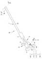
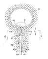
図1は本発明の実施形態に係る内視鏡を示す概略斜視図、図2は図1の2−2線に沿う断面図、図3は図2の3−3線に沿う断面図、図4は図2の4−4線に沿う断面図である。 1 is a schematic perspective view showing an endoscope according to an embodiment of the present invention, FIG. 2 is a sectional view taken along line 2-2 in FIG. 1, FIG. 3 is a sectional view taken along line 3-3 in FIG. 4 is a cross-sectional view taken along line 4-4 of FIG.
本実施形態は、内視鏡を尿失禁の治療に使用する場合であり、尿道あるいは尿管に挿入し、生体適合性注入剤を尿道外括約筋に隣接する近位尿道周囲あるいは尿管口に隣接する体組織への注入に使用する。 In this embodiment, an endoscope is used for the treatment of urinary incontinence. The endoscope is inserted into the urethra or ureter, and the biocompatible injection is placed around the proximal urethra adjacent to the extraurethral sphincter or adjacent to the ureteral opening. Used for injection into body tissue.
本実施形態の内視鏡Nは、図1に示すように、長尺な管状の本体1と、本体1の後端に連結されたブリッジ部2を介して設けられた操作部3と、操作部3の後端に設けられた接眼部4とを有し、操作部3には、光源からの光を導入するために上方に突出されたライトコネクタ5と、ブリッジ部2に連結された操作導管6が設けられている。 As shown in FIG. 1, the endoscope N of the present embodiment includes a long tubular
さらに詳述する。まず、本体1は、図2に示すように、治療のため尿道あるいは尿管に挿入される部分であって、先端が開放端とされたシース10を有している。シース10は、特に限定されないが、本体1をより細径化し比較的柔軟なものにする場合には、薄層チューブとすることが好ましく、その材質としては、例えば、ポリイミド、ポリウレタン、ポリエチレン、ポリテトラフルオロエチレンなどが使用でき、また、柔軟でなく剛性のあるものにする場合には、SUS材などが使用できる。 Further details will be described. First, as shown in FIG. 2, the
シース10の内部には、3つのルーメン11,12,13と、ライトガイド30とイメージガイド31が軸方向の略全長にわたって設けられている。 Inside the
まず、ルーメンに関して述べると、図2の右側の第1のルーメン11は、針用ルーメンであり、図4に示すように、先端に注入針Hが設けられた注入用カテーテル14が挿通されている。注入用カテーテル14は、第1のルーメン11と操作導管6を通って外部まで導かれ、外端部には、生体適合性注入剤を注入する注入手段(図示せず)が連結されている。なお、注入手段としては、どのようなものであってもよいが、具体的には、シリンジポンプなどが使用される。また、注入用カテーテル14は、外部から操作することにより全体が第1ルーメン11内で軸方向に進退し、先端に設けられた注入針Hがシース10の先端から出没自在するようになっている。 First, regarding the lumen, the
ここに、注入針Hは、本実施形態では、コアリング針、非コアリング針のいずれを使用してもよいが、注入針Hにより注入されるコラーゲンなどの生体適合性注入剤は、比較的粘性を有しているため、これを円滑に注入するには、ある程度の内径を有することが好ましく、例えば、注入針Hは、内径が0.5mm〜1.5mm程度が好ましい。また、注入用カテーテル14の内径としては、0.7mm〜2.5mm程度で、かつテーパ形状のものが好ましい。 Here, the injection needle H may use either a coring needle or a non-coring needle in this embodiment, but a biocompatible injection agent such as collagen injected by the injection needle H is relatively Since it has viscosity, in order to inject it smoothly, it preferably has a certain inner diameter. For example, the injection needle H preferably has an inner diameter of about 0.5 mm to 1.5 mm. Further, the inner diameter of the
図上左側の第2のルーメン12は、偏在手段15を膨張するためのルーメンである。 The
偏在手段15とは、注入針Hを深い穿刺角度で穿刺できるように、穿刺位置近傍の体組織を歪ませ、穿刺面に対する穿刺角度を大きくし、注入針Hの穿刺位置を正確にコントロールして最適注入箇所に注入針Hを進めることができるようにするものである。 The uneven distribution means 15 distorts the body tissue in the vicinity of the puncture position so that the injection needle H can be punctured at a deep puncture angle, increases the puncture angle with respect to the puncture surface, and accurately controls the puncture position of the injection needle H. The injection needle H can be advanced to the optimal injection location.
本実施形態の偏在手段15は、図4に示すように、シース10の先端側側部の外面に設けられた偏在用バルーン16と、この偏在用バルーン16に流体圧を導入するための加圧手段17(図1参照)と、加圧手段17を制御する制御手段18(図1参照)とから構成されている。偏在用バルーン16は、シース10に開設された通孔19を介して第2のルーメン12及び操作導管6の基部側に設けられたポート24に連通している。そして、ポート24の外端部に加圧手段17と制御手段18が連結されている。 As shown in FIG. 4, the uneven distribution means 15 of the present embodiment includes the
偏在用バルーン16の材質としては、シリコン、ポリウレタンあるいはスチレン系エラストマーなどの弾性率が低く、かつ伸びが大きいものが好適に使用される。理由は、収縮時はシース10の外面との段差が少なく、膨張時はシース10の外部に大きく突出させることができるからである。 As the material for the unevenly
加圧手段17としては、例えば、シリンジポンプあるいはローラポンプなどが使用され、空気などの気体あるいは生理食塩水などの液体を、ポート24より第2のルーメン12を通って通孔19まで供給し、偏在用バルーン16を膨張させる。また、制御手段18は、シリンジポンプあるいはローラポンプなどの作動を制御し、円滑に流体圧を導入させるようになっている。なお、加圧手段17であるシリンジポンプを手動操作する場合には、制御手段18は必ずしも設ける必要はない。 As the pressurizing means 17, for example, a syringe pump or a roller pump is used, and a gas such as air or a liquid such as physiological saline is supplied from the
加圧膨張された偏在用バルーン16は、シース10の外部に大きく突出し、体腔内壁面を加圧することによりシース10の先端を変位させ、穿刺位置近傍の体組織を歪ませるようになっている。 The unevenly-distributed
特に、偏在用バルーン16による注入用カテーテル14の変位を効率的に行わせるためには、第1ルーメン11に対する第2ルーメン12の位置を、シース10あるいは本体1の中心軸線に対し対向する位置にすることが好ましい。このようにすると、偏在用バルーン16を膨張させたときの膨張量がそのままシース10の先端部の変位量となって表れ、シース10の先端部の位置、つまり、注入用カテーテル14に設けられた注入針Hの位置を極めて円滑に変位させることができる。ただし、第1ルーメン11に対する第2ルーメン12の位置は、必ずしも前記中心軸線に対する対向位置(直交する位置)のみでなく、効率は低下するが、交差角が90度以外であってもよい。 In particular, in order to efficiently displace the
なお、偏在手段15は、偏在用バルーン16のみでなく、シース10の先端側側部より突出し得る弾性部材(図示せず)により構成してもよい。弾性部材としては、ばねあるいはエラストマーなど種々のものを使用できるが、シース10より外部に突出する突出量を制御手段により制御し得るように構成することが好ましい。例えば、弾性部材としてばねを使用した場合には、突出量を制御できるダンパー手段を有するものを使用することが好ましく、また、エラストマーの場合には突出量を制御できる加圧手段を内部などに設けることが好ましい。特に、ばねを使用した場合には、尿道内壁を傷つけることなく加圧できるように、何らかのクッション部材を設けることが好ましい。 In addition, the uneven distribution means 15 may be comprised not only of the
図2の下側の第3のルーメン13は、位置決め制御用ルーメンであり、ここには、位置決め制御用バルーンカテーテル20が設けられている。位置決め用バルーンカテーテル20は、第3のルーメン13及び操作導管6を通って外部まで導かれ、その外端部に、このカテーテル20に流体圧を導入するための加圧手段17(図3参照)と、加圧手段17などを制御する制御手段21(図3参照)が連結されている。The
位置決め制御用バルーンカテーテル20により形成される位置決め用バルーンBは、膀胱内部まで挿入した本体1の先端から押し出して膀胱内で膨張させ、膀胱頚部42(図5参照)に係合することにより本体1の位置決めをするものである。なお、位置決め用バルーンBは、偏在用バルーン16と同様の材質で形成することが好ましい。 The positioning balloon B formed by the positioning
特に、本実施形態では、位置決め制御用バルーンカテーテル20のカテーテルシャフト22内に圧力センサー23が設けられている。注入針Hから体組織に生体適合性注入剤を注入すると、体組織の一部が膨隆することになるが、この膨隆状態により高められた癒合圧力を圧力センサー23により検知し、膨隆の形成度を測定し、注入剤の注入不足や過度の注入を防止している。 In particular, in this embodiment, a
したがって、圧力センサー23を設ける位置は重要で、尿失禁の治療の場合には、位置決め用バルーンBの基端から1.0cm離間された点を中心に±0.5cmの範囲内に設けると、尿失禁の治癒率が高く、好ましいことが実験により判明している。この場合、圧力センサー23は、前記範囲内に1個設けてもよいが、複数個設けると、この範囲内での膨隆の形成度が判明し、より治療がより確実なものとなる。 Therefore, the position where the
位置決め用バルーンBの加圧手段17としては、前記偏在用バルーン16と同様、シリンジポンプあるいはローラポンプなどが使用され、空気などの気体あるいは生理食塩水などの液体を先端部まで供給し、位置決め用バルーンBを形成する。 As the pressurizing means 17 of the positioning balloon B, a syringe pump or a roller pump is used as in the case of the unevenly distributed
制御手段21は、前記偏在用バルーン16の制御手段18と同様、シリンジポンプあるいはローラポンプなどの作動を制御するが、これのみでなく、圧力センサー23からの情報も入力され、モニターで表示したり、測定した癒合圧力から最適な注入剤の量などを演算するなど、各種処理を行うようになっている。 The control means 21 controls the operation of a syringe pump or a roller pump, similar to the control means 18 of the unevenly distributed
本実施形態の圧力センサー23は、電気的に感圧するものであり、位置決め制御用バルーンカテーテル20内に設けられた導線(図示せず)を介して制御手段21と接続されている。ただし、圧力センサー23は、膨隆状態により変化する圧力を検知するものであれば、どのようなものであってもよく、電気的なもののみでなく、力学的に感知するセンサーを使用することもできる。例えば、位置決め用バルーンBを形成するために、位置決め制御用バルーンカテーテル20内に供給される流体を利用し、圧力変動が生じると、位置決め制御用バルーンカテーテル20の端部に設けられたダイアフラムなどを変位させ、これにより圧力変動を感知してもよい。このようにすれば、導線なども不要で、構成の簡略化を図ることができ、装置コストも低減できる。 The
このようにして検知された癒合圧力の情報は、制御手段21に伝達され、注入状態あるいは圧力状態をモニターで表示し、術者に知らしめるが、情報の伝達は、必ずしも導線や流体を用いるもののみでなく、通信により行なってもよい。 Information on the fusion pressure detected in this way is transmitted to the control means 21, and the injection state or pressure state is displayed on the monitor to inform the operator, but the information is not necessarily transmitted using a wire or fluid. It may be performed by communication as well.
図2に示すように、シース10には、複数本のライトガイド30と1本のイメージガイド31が設けられている。 As shown in FIG. 2, the
ライトガイド30は、暗部観察時に必要な照明光を照射するためのもので、操作部3のライトコネクタ5を通じて照射された光をシース10の先端部の前方へ導光する。 The
イメージガイド31は、多数の光透過性のコア32と、これらを固定するクラッド33とから構成されている。イメージガイド31は、シース10の先端に設けられたレンズ34により結像した被写体の像を、接眼部4に導くものである。 The
コア32の材質は、クラッド33よりも屈折率が大きいものであれば特に限定されないが、本体1を柔軟に形成する場合には、可撓性の優れているプラスチック製であることが好ましい。プラスチックの種類としては、例えば、ポリメチルメタクリレート、ポリスチレン、スチレンアクリロニトリル、ポリカーボネート、ポリクロロスチレン等が挙げられる。 The material of the
クラッド33の材質はプラスチックが好ましい。プラスチック材料の種類はクラッドとしての機能を発揮するものであれば特に限定されるものではないが、例えば、ポリメチルメタクリレート、ポリスチレン、ポリカーボネート、ポリエチレン、ポリアミド等が挙げられる。 The clad 33 is preferably made of plastic. The type of plastic material is not particularly limited as long as it exhibits a function as a clad, and examples thereof include polymethyl methacrylate, polystyrene, polycarbonate, polyethylene, and polyamide.
なお、レンズ34は、被写体の像を結像させることができるものであれば種類は問わないが、ロッドレンズを用いることが好ましい。イメージガイド31への装着を容易にすることができるからである。 The
次に、本実施形態の作用を説明する。 Next, the operation of this embodiment will be described.
まず、術者は、操作導管6から導出された注入用カテーテル14の外端に、生体適合性注入剤が充填されたシリンジポンプを、ポート24と位置決め用バルーンカテーテル20の外端に、それぞれ加圧用のシリンジポンプを連結する。ライトガイド30、イメージガイド31も作動状態とすると、セットが完了する。 First, the operator applies a syringe pump filled with a biocompatible injection agent to the outer end of the
次に、イメージガイド31からの像を接眼部4で目視しつつ本体1を、図5に示すように、外尿道口から尿道40を通り、先端が膀胱41内に達するまで挿入する。 Next, while viewing the image from the
この状態で、まず、注入針Hの先端から注入剤を流出させ、注入針Hの内腔内の空気を抜いた後、注入針Hを内視鏡N内に戻す。次に、位置決め用バルーンカテーテル20のシリンジポンプ17を作動し、膀胱41内で位置決め用バルーンBを膨張させる。位置決め用バルーンBは、内視鏡Nの先端直前で膨張するので、位置決め用バルーンBと共に内視鏡Nを後退させると、位置決め用バルーンBは膀胱頚部42に直ちに当接する。この位置決め用バルーンBと膀胱頚部42との当接からさらに内視鏡Nを所定の後退長L(約1.5cm〜2.0cm程度)だけ後退させる(図5に示す状態)と、この付近が丁度尿道外括約筋付近であり注入剤の注入位置でもあるので、内視鏡Nが軸方向に移動しないように位置決め用バルーンカテーテル20と内視鏡Nをロックする。 In this state, first, the injection agent is caused to flow out from the tip of the injection needle H, the air in the lumen of the injection needle H is evacuated, and then the injection needle H is returned into the endoscope N. Next, the
ロックは、どのような手段であってもよいが、例えば、位置決め用バルーンカテーテル20を作業導管6の出口端でクリップなどのストッパ部材S(図1参照)によりロックし、内視鏡Nを軸方向不動とする。 The locking may be any means, for example, the
このロック状態で、接眼部4で目視しつつ偏在手段15を作動する。つまり、図6に示すように、偏在用バルーン16と連通した加圧用のシリンジポンプを加圧し、偏在用バルーン16を膨張させる。 In this locked state, the uneven distribution means 15 is operated while visually observing with the eyepiece 4. That is, as shown in FIG. 6, the pressurizing syringe pump communicated with the
偏在用バルーン16は、加圧手段17及び制御手段18により加圧流体の供給を制御しつつ徐々に膨張し、シース10の外部に大きく突出し、一方の尿道内壁面40aを加圧する。この尿道内壁面40aの加圧に伴ってシース10の先端も、偏在用バルーン16の膨張方向とは反対側に変位し、シース10の先端が尿道内壁面40aとは反対側の尿道内壁面40bを歪ませる。 The unevenly distributed
注入針Hを有する注入用カテーテル14は、偏在用バルーン16の対向位置に配置されているので、本体1の先端部の変位は円滑で、変位量も応答性のよいものが得られる。したがって、注入針Hを穿刺する場合には、穿刺すべき尿道内壁面が直前に存在することになり、深い穿刺角度で穿刺できる状態になる。 Since the
術者は、偏在用バルーン16の膨張に伴う変化状態を接眼部4で目視しつつ内視鏡Nを水平状態から、例えば、いわゆる4時の穿刺位置となるように回動する。所定位置に達すると、加圧膨張用のシリンジポンプの加圧を停止する。そして、外部から注入用カテーテル14を操作し、尿道粘膜43に穿刺し、加圧用シリンジポンプを作動し、内部の注入剤を注入する。注入剤の注入により尿道管の内壁の一部が膨隆することになる。注入後、注入針Hを抜き、1〜2分間見守る。傷口が閉鎖し、注入剤が漏出しないことを確認すると、これで一方の注入は完了することになる。 The surgeon rotates the endoscope N from a horizontal state to a so-called 4 o'clock puncture position, for example, while visually observing the state of change associated with the expansion of the unevenly distributed
次に、偏在用バルーン16と連通した加圧用のシリンジポンプを作動し、偏在用バルーン16を収縮させる。そして、前記4時の穿刺位置にある内視鏡Nを水平状態に戻す。 Next, the pressurizing syringe pump communicated with the
内視鏡Nを反転させた後、再度、加圧用のシリンジポンプを作動し、偏在用バルーン16を膨張させ、シース10の先端を前記同様変位させ、シース10の先端で尿道内壁面40bを歪ませる。 After inverting the endoscope N, the syringe pump for pressurization is actuated again to inflate the
術者は、この変化状態を接眼部4で目視しつつ、偏在用バルーン16が膨張している状態のまま内視鏡Nを水平状態から、いわゆる8時の穿刺位置となるように回動し、所定位置に達すると、加圧用のシリンジポンプの加圧を停止する。そして、前記同様、外部から注入用カテーテル14を操作して尿道粘膜43に穿刺し、加圧用のシリンジポンプにより注入剤を注入する。 The operator turns the endoscope N from the horizontal state to the so-called puncture position at 8 o'clock while keeping the
注入剤の注入により尿道管の内壁の一部が膨隆することになる。この膨隆状態により高められた尿道管の内壁の癒合圧力により位置決め制御用バルーンカテーテル20が加圧され、癒合圧力を圧力センサー23が検知する。注入剤の注入に伴って癒合圧力が上昇し、この値が外部の制御手段21に伝達されるので、術者は、この値により膨隆の形成状態を知ることができる。所定の膨隆状態が形成されたことを確認すると、加圧用のシリンジポンプの作動を停止する。この結果、注入剤の注入不足や過度の注入が防止できる。 A portion of the inner wall of the urethral tube bulges due to the injection of the injection. The positioning
そして、注入針Hを抜き、傷口の閉鎖や、注入剤の漏出がないことを確認すると、これで両方の注入が完了する。注入完了後は、偏在用バルーン16や位置決め用バルーンBを収縮させてシース10内に収容する。そして、内視鏡Nを生体から抜去する。 Then, when the injection needle H is pulled out and it is confirmed that there is no closing of the wound or leakage of the injection agent, both injections are completed. After the injection is completed, the
本発明は、上述した実施形態のみに限定されるものではなく、本発明の技術的思想内において当業者により種々変更が可能である。例えば、前述した実施形態は、尿道を狭くする尿失禁の治療に使用されるものであるが、本発明は、これのみに限定されるものではなく、食道と胃との間の噴門あるいは胃と十二指腸との間の幽門を狭くする治療にも使用可能である。 The present invention is not limited to the above-described embodiments, and various modifications can be made by those skilled in the art within the technical idea of the present invention. For example, the embodiment described above is used for the treatment of urinary incontinence that narrows the urethra, but the present invention is not limited to this, and the cardia or stomach between the esophagus and the stomach It can also be used to narrow the pylorus between the duodenum.
本発明は、尿失禁の治療を、簡単かつ安全に行うことができる内視鏡として利用できる。 The present invention can be used as an endoscope that can easily and safely treat urinary incontinence.
1…本体、
14…注入用カテーテル、
15…偏在手段、
16…偏在用バルーン、
17…加圧手段、
18…制御手段、
19…通孔、
20…位置決め用バルーンカテーテル、
23…圧力センサー、
24…ポート、
B…位置決め用バルーン、
H…注入針、
N…内視鏡、
S…ストッパ部材。1 ... body,
14 ... Infusion catheter,
15 ... uneven distribution means,
16 ... unevenly distributed balloon,
17 ... Pressure means,
18 ... control means,
19 ... through holes,
20 ... Balloon catheter for positioning,
23 ... Pressure sensor,
24 ... Port,
B ... Balloon for positioning,
H ... Injection needle,
N ... Endoscope,
S: Stopper member.
Claims (4)
Translated fromJapanese前記本体の第1ルーメンに対向する位置の第2ルーメン内に設けられ、前記体組織を加圧し前記本体の先端部を前記体腔内で変位させる偏在手段と、
前記バルーンカテーテルのカテーテルシャフト内に設けられ、前記注入針から体組織に注入された生体適合性注入剤により形成される膨隆による癒合圧力を測定する圧力センサーと、
を有する内視鏡。A main bodyhaving three lumens , inserted into a body cavity, an injection needle provided so as to be ableto protrude and retract fromthe first lumen of the main body and injecting a biocompatible injectable agent into the body tissue, and athird lumen of the main body In an endoscope having a balloon catheterprovided at a distal end and having a balloon placed in the neck of the body cavity,
Provided in a second lumen at a position opposite to the first lumen of the main body, pressurizing the body tissue and displacing the distal end of the main body within the body cavity;
A pressure sensor for measuring theprovided balloon cathetercatheter shaft, fusion pressure due bulge formed by a biocompatible infusate injected into body tissue from the injectionneedle,
Endoscopehaving a.
Priority Applications (1)
| Application Number | Priority Date | Filing Date | Title |
|---|---|---|---|
| JP2006091310AJP4920279B2 (en) | 2006-03-29 | 2006-03-29 | Endoscope |
Applications Claiming Priority (1)
| Application Number | Priority Date | Filing Date | Title |
|---|---|---|---|
| JP2006091310AJP4920279B2 (en) | 2006-03-29 | 2006-03-29 | Endoscope |
Publications (2)
| Publication Number | Publication Date |
|---|---|
| JP2007260241A JP2007260241A (en) | 2007-10-11 |
| JP4920279B2true JP4920279B2 (en) | 2012-04-18 |
Family
ID=38633807
Family Applications (1)
| Application Number | Title | Priority Date | Filing Date |
|---|---|---|---|
| JP2006091310AExpired - Fee RelatedJP4920279B2 (en) | 2006-03-29 | 2006-03-29 | Endoscope |
Country Status (1)
| Country | Link |
|---|---|
| JP (1) | JP4920279B2 (en) |
Families Citing this family (5)
| Publication number | Priority date | Publication date | Assignee | Title |
|---|---|---|---|---|
| DE602009001050D1 (en) | 2008-06-04 | 2011-05-26 | Olympus Medical Systems Corp | Capsular medical device |
| JP5173611B2 (en)* | 2008-06-04 | 2013-04-03 | オリンパスメディカルシステムズ株式会社 | Capsule medical device |
| JP7228781B2 (en)* | 2017-10-31 | 2023-02-27 | パナソニックIpマネジメント株式会社 | Purification device and purification method |
| WO2019087745A1 (en)* | 2017-10-31 | 2019-05-09 | パナソニックIpマネジメント株式会社 | Cleaning device and cleaning method |
| CN120254194B (en)* | 2025-06-03 | 2025-08-19 | 江苏科标医学技术集团有限公司 | Balloon catheter biocompatibility testing device |
Family Cites Families (5)
| Publication number | Priority date | Publication date | Assignee | Title |
|---|---|---|---|---|
| JPS5671205A (en)* | 1979-11-15 | 1981-06-13 | Matsushita Electric Works Ltd | Head light |
| JPS6037495B2 (en)* | 1981-05-22 | 1985-08-27 | 株式会社日立製作所 | data transfer device |
| US6096009A (en)* | 1996-09-13 | 2000-08-01 | Boston Scientific Corporation | Guidewire and catheter locking device and method |
| JP2000014663A (en)* | 1998-06-30 | 2000-01-18 | Olympus Optical Co Ltd | Therapy device for prostatic hypertrophy |
| JP2000232981A (en)* | 1999-02-15 | 2000-08-29 | Olympus Optical Co Ltd | Puncture ultrasonic endoscope device for lumen and balloon catheter for ultrasonic endoscope |
- 2006
- 2006-03-29JPJP2006091310Apatent/JP4920279B2/ennot_activeExpired - Fee Related
Also Published As
| Publication number | Publication date |
|---|---|
| JP2007260241A (en) | 2007-10-11 |
Similar Documents
| Publication | Publication Date | Title |
|---|---|---|
| US5836951A (en) | Balloon dilation catheter | |
| US5007898A (en) | Balloon dilatation catheter | |
| US5312430A (en) | Balloon dilation catheter | |
| US5830228A (en) | Methods and systems for deployment of a detachable balloon at a target site in vivo | |
| US5030227A (en) | Balloon dilation catheter | |
| CA2709783C (en) | Guide tube equipped with balloon for puncture | |
| CA2283827C (en) | Balloon catheter for puncturing, medical tube introducing device using the catheter and method for use thereof | |
| ES2929743T3 (en) | dilatable balloon catheter | |
| JPH07275370A (en) | Equipment and method to infuse viscous material into tissue of patient | |
| JP2004329485A (en) | Chemical injection device | |
| JP4847774B2 (en) | Endoscope | |
| JP4920279B2 (en) | Endoscope | |
| CN110339461B (en) | Balloon catheter capable of passing guide wire under guidance of endoscope | |
| US20050288639A1 (en) | Instrument used in treatment of the urinary incontinence in women | |
| US20140243783A1 (en) | Method of backflow reduction during material delivery through a needle into tissue | |
| JP2018509249A (en) | Catheter with balloon at the tip for continuous nerve block | |
| US9925357B2 (en) | Access sheath | |
| US20200230378A1 (en) | Balloon catheter system and method for optical tumor treatment | |
| JP4827818B2 (en) | Fluid supply body | |
| JP7301291B2 (en) | Catheter and oxygen partial pressure measurement method | |
| CN211357363U (en) | Self-guiding balloon catheter under endoscope | |
| JP4268260B2 (en) | Luminescent injection needle | |
| CN211094536U (en) | Bladder puncture fistulization external member | |
| CN216824288U (en) | Ureter guide sheath with pressure measuring and controlling functions | |
| CN114431924B (en) | Ureter expansion device |
Legal Events
| Date | Code | Title | Description |
|---|---|---|---|
| A621 | Written request for application examination | Free format text:JAPANESE INTERMEDIATE CODE: A621 Effective date:20090212 | |
| A977 | Report on retrieval | Free format text:JAPANESE INTERMEDIATE CODE: A971007 Effective date:20110526 | |
| A131 | Notification of reasons for refusal | Free format text:JAPANESE INTERMEDIATE CODE: A131 Effective date:20110607 | |
| A521 | Written amendment | Free format text:JAPANESE INTERMEDIATE CODE: A523 Effective date:20110721 | |
| TRDD | Decision of grant or rejection written | ||
| A01 | Written decision to grant a patent or to grant a registration (utility model) | Free format text:JAPANESE INTERMEDIATE CODE: A01 Effective date:20120124 | |
| A01 | Written decision to grant a patent or to grant a registration (utility model) | Free format text:JAPANESE INTERMEDIATE CODE: A01 | |
| A61 | First payment of annual fees (during grant procedure) | Free format text:JAPANESE INTERMEDIATE CODE: A61 Effective date:20120201 | |
| R150 | Certificate of patent or registration of utility model | Free format text:JAPANESE INTERMEDIATE CODE: R150 | |
| FPAY | Renewal fee payment (event date is renewal date of database) | Free format text:PAYMENT UNTIL: 20150210 Year of fee payment:3 | |
| LAPS | Cancellation because of no payment of annual fees |