JP4918903B2 - Decoding processing program, decoding processing method, and decoding processing apparatus - Google Patents
Decoding processing program, decoding processing method, and decoding processing apparatusDownload PDFInfo
- Publication number
- JP4918903B2 JP4918903B2JP2007255194AJP2007255194AJP4918903B2JP 4918903 B2JP4918903 B2JP 4918903B2JP 2007255194 AJP2007255194 AJP 2007255194AJP 2007255194 AJP2007255194 AJP 2007255194AJP 4918903 B2JP4918903 B2JP 4918903B2
- Authority
- JP
- Japan
- Prior art keywords
- decoding
- image data
- blocks
- input device
- code
- Prior art date
- Legal status (The legal status is an assumption and is not a legal conclusion. Google has not performed a legal analysis and makes no representation as to the accuracy of the status listed.)
- Active
Links
Images


Landscapes
- Image Processing (AREA)
- Editing Of Facsimile Originals (AREA)
- Facsimile Image Signal Circuits (AREA)
Description
Translated fromJapaneseこの発明は、入力機器によって撮影された画像データを取得し、当該画像データに埋め込まれたコードのデコード処理を行うデコード処理プログラム、デコード処理方法およびデコード処理装置に関する。 The present invention relates to a decoding processing program, a decoding processing method, and a decoding processing device that acquire image data captured by an input device and perform a decoding process on a code embedded in the image data.
従来より、隣接ブロックの平均濃度の差を使用して隣接ブロックのペアにコードを埋め込むコード埋め込み技術がある。例えば、特許文献1に開示された画像処理装置では、コード埋め込み技術により画像にステガノグラフィコードを埋め込んだ後、カメラ等の入力装置によって撮影された画像データを取得してデコード処理を行う。このデコード処理においては、入力画像データの隣接ブロックの階調レベルの差から元のコードをデコードする処理を行っている(図10参照)。 Conventionally, there is a code embedding technique for embedding a code in a pair of adjacent blocks using a difference in average density of adjacent blocks. For example, in the image processing apparatus disclosed in Patent Document 1, a steganography code is embedded in an image by a code embedding technique, and then image data captured by an input device such as a camera is acquired and decoded. In this decoding process, the original code is decoded from the difference in gradation level between adjacent blocks of the input image data (see FIG. 10).
このデコードする処理について具体的に説明すると、カメラ等の入力機器のデフォルトの固定設定値(例えば、適正焦点距離や視野範囲など)を用いて画像取得を行い、取得された画像に対して、コードの埋め込まれた画像領域(コード領域)を検出し、検出領域を複数のブロックに分割し、各ブロックの階調レベルを算出し、隣接ブロック(ブロックペア)の階調レベルの大小関係(レベル差)から埋め込まれたデータを取り出す。 Specifically, the decoding process will be described. Image acquisition is performed using a default fixed setting value of an input device such as a camera (for example, an appropriate focal length, a visual field range, etc.). Is detected, the detection area is divided into a plurality of blocks, the gradation level of each block is calculated, and the gradation level relationship between adjacent blocks (block pairs) (level difference) ) To retrieve the embedded data.
ところで、上記した従来の技術では、入力機器のデフォルトの固定設定値を用いて画像データの取得を行っていたので、適正焦点距離での撮影画像データ中のコード埋め込み領域の大きさを調整できないため、画素解像度が不足してデコードに失敗したり、撮影時の入力機器の入出力特性の設定が不適切なため、一部のブロックの階調レベル差を正しく取得できずにデコードに失敗するという問題があった。 By the way, in the above-described conventional technology, since the image data is acquired using the default fixed setting value of the input device, the size of the code embedding area in the captured image data at the appropriate focal length cannot be adjusted. , Decoding fails due to insufficient pixel resolution, or the input / output characteristics of the input device at the time of shooting are improperly set. There was a problem.
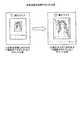
つまり、入力機器の適正焦点距離や視野範囲を固定設定値としているため、印刷紙面上のコード領域の大きさと撮影距離によって画像中のコード領域のサイズとボケ具合が変わる。例えば、適正焦点距離での視野範囲が広い場合には、入力画像中のコード領域のサイズが小さく、デコードに必要な画素解像度(コード領域に含まれる画素数)が不足し、階調レベルを正しく算出できずデコードに失敗する(図11の(1)参照)。一方、撮影距離を近づけて、入力画像中のコード領域が適正サイズになるよう撮影距離を近づけると、画像がボケてしまい、階調レベルを正しく算出できずデコードに失敗する(図11の(2)参照)。 In other words, since the appropriate focal length and field of view range of the input device are set as fixed values, the size and blur condition of the code area in the image change depending on the size of the code area on the printing paper and the shooting distance. For example, when the visual field range at a proper focal length is wide, the size of the code area in the input image is small, the pixel resolution (number of pixels included in the code area) necessary for decoding is insufficient, and the gradation level is correct. It cannot be calculated and decoding fails (see (1) in FIG. 11). On the other hand, if the shooting distance is reduced and the shooting distance is reduced so that the code area in the input image has an appropriate size, the image will be blurred, and the gradation level cannot be calculated correctly and decoding fails ((2 in FIG. 11). )reference).
また、図12に示すように、入力機器の入出力特性の非線形性(明るさ、コントラスト調整による明暗部分の階調潰れ)により、入力画像におけるブロックペアの階調レベルの差が撮影画像では平坦になってしまう領域(不感領域)が生じ、本来あるはずの階調レベル差が無くなってしまいデコードに失敗する。 In addition, as shown in FIG. 12, the difference in the gradation level of the block pair in the input image is flat in the photographed image due to nonlinearity of the input / output characteristics of the input device (the gradation of the light and dark portions is reduced by brightness and contrast adjustment). This results in an area (insensitive area) that becomes, and the gradation level difference that should originally exist disappears, and decoding fails.
そこで、この発明は、上述した従来技術の課題を解決するためになされたものであり、取得画像データの画質を適正化して、デコード性能を向上することを目的とする。 Therefore, the present invention has been made to solve the above-described problems of the prior art, and aims to improve the decoding performance by optimizing the image quality of acquired image data.
上述した課題を解決し、目的を達成するため、本発明は、入力機器によって撮影された画像データを取得し、当該画像データに埋め込まれたコードのデコード処理を行うデコード処理方法をコンピュータに実行させるデコード処理プログラムであって、コードのデコード処理が成功したか否かを判定するデコード判定手順と、前記デコード判定手順によって前記デコード処理が成功しなかったと判定された場合には、前記画像データ取得時の画像取得特性を調整する画像取得特性調整手順と、をコンピュータに実行させることを特徴とする。 In order to solve the above-described problems and achieve the object, the present invention causes a computer to execute a decoding processing method for acquiring image data taken by an input device and decoding a code embedded in the image data. A decoding processing program for determining whether or not the decoding processing of the code is successful; and when the decoding processing determines that the decoding processing is not successful by the decoding determination procedure, And an image acquisition characteristic adjustment procedure for adjusting the image acquisition characteristic.
また、本発明は、上記の発明において、前記画像取得特性調整手順は、前記画像取得特性として、前記画像データに埋め込まれたコードの領域の大きさが所定の範囲内となるように、前記入力機器のズーム値を調整することを特徴とする。 Also, in the present invention according to the above invention, the image acquisition characteristic adjustment procedure may be configured so that the size of a code area embedded in the image data is within a predetermined range as the image acquisition characteristic. The zoom value of the device is adjusted.
また、本発明は、上記の発明において、前記画像取得特性調整手順は、前記画像取得特性として、前記画像データに埋め込まれたコードの領域をブロック分割し、各ブロックの階調レベルを算出し、当該階調レベルが所定範囲内にあるブロックの数が、所定の割合より小さくなるように、前記入力機器の入出力特性を調整することを特徴とする。 Further, in the present invention according to the above-described invention, the image acquisition characteristic adjustment procedure divides a code area embedded in the image data into blocks as the image acquisition characteristic, and calculates a gradation level of each block. The input / output characteristics of the input device are adjusted so that the number of blocks in which the gradation level is within a predetermined range is smaller than a predetermined ratio.
また、本発明は、上記の発明において、前記画像取得特性調整手順によって前記画像取得特性の調整が行われた後の設定パラメータを設定パラメータ記憶部に格納する設定パラメータ記憶手順をさらにコンピュータに実行させることを特徴とする。 In the present invention, the computer further causes the computer to execute a setting parameter storage procedure for storing the setting parameter in the setting parameter storage unit after the adjustment of the image acquisition characteristic by the image acquisition characteristic adjustment procedure. It is characterized by that.
また、本発明は、上記の発明において、前記デコード判定手順は、前記画像取得特性調整手順によって前記画像取得特性の調整が行われた後に、コードのデコード処理が成功したか否かを再度判定することを特徴とする。 Also, in the present invention according to the above invention, the decoding determination procedure determines again whether or not the code decoding process has succeeded after the adjustment of the image acquisition characteristics by the image acquisition characteristics adjustment procedure. It is characterized by that.
また、本発明は、上記の発明において、入力機器によって撮影された画像データを取得し、当該画像データに埋め込まれたコードのデコード処理を行うデコード処理方法であって、コードのデコード処理が成功したか否かを判定するデコード判定ステップと、前記デコード判定ステップによって前記デコード処理が成功しなかったと判定された場合には、前記画像データ取得時の画像取得特性を調整する画像取得特性調整ステップと、を含んだことを特徴とする。 Further, the present invention is a decoding processing method for acquiring image data taken by an input device and decoding a code embedded in the image data in the above invention, and the code decoding process has succeeded. A decoding determination step for determining whether or not, and when the decoding determination step determines that the decoding process has not been successful, an image acquisition characteristic adjustment step for adjusting an image acquisition characteristic at the time of acquiring the image data; It is characterized by including.
また、本発明は、上記の発明において、前記画像取得特性調整ステップは、前記画像取得特性として、前記画像データに埋め込まれたコードの領域の大きさが所定の範囲内となるように、前記入力機器のズーム値を調整することを特徴とする。 Also, in the present invention according to the above invention, the image acquisition characteristic adjusting step may be configured such that the image acquisition characteristic is adjusted such that a size of a code area embedded in the image data is within a predetermined range. The zoom value of the device is adjusted.
また、本発明は、上記の発明において、前記画像取得特性調整ステップは、前記画像取得特性として、前記画像データに埋め込まれたコードの領域をブロック分割し、各ブロックの階調レベルを算出し、当該階調レベルが所定範囲内にあるブロックの数が、所定の割合より小さくなるように、前記入力機器の入出力特性を調整することを特徴とする。 Also, in the present invention according to the above-described invention, the image acquisition characteristic adjustment step divides a code area embedded in the image data into blocks as the image acquisition characteristic, and calculates a gradation level of each block, The input / output characteristics of the input device are adjusted so that the number of blocks in which the gradation level is within a predetermined range is smaller than a predetermined ratio.
また、本発明は、上記の発明において、前記画像取得特性調整ステップによって前記画像取得特性の調整が行われた後の設定パラメータを設定パラメータ記憶部に格納する設定パラメータ記憶ステップをさらに含んだことを特徴とする。 The present invention further includes a setting parameter storage step of storing, in the setting parameter storage unit, a setting parameter after the adjustment of the image acquisition characteristic in the image acquisition characteristic adjustment step. Features.
また、本発明は、上記の発明において、入力機器によって撮影された画像データを取得し、当該画像データに埋め込まれたコードのデコード処理を行うデコード処理装置であって、コードのデコード処理が成功したか否かを判定するデコード判定手段と、前記デコード判定手段によって前記デコード処理が成功しなかったと判定された場合には、前記画像データ取得時の画像取得特性を調整する画像取得特性調整手段と、を備えたことを特徴とする。 Further, the present invention is the decoding processing device according to the above invention, which acquires image data taken by an input device and decodes a code embedded in the image data, and the code decoding process is successful. A decoding determination unit that determines whether or not the image acquisition characteristic adjustment unit that adjusts an image acquisition characteristic at the time of acquiring the image data when the decoding determination unit determines that the decoding process has not been successful; It is provided with.
本発明によれば、デコード処理の結果に応じて、撮影画像中のコード埋め込み領域の大きさや、入力機器の階調レベルの入出力特性を調整しながらデコード処理を行い、従来の固定設定値を用いたまま撮影を行った場合にはデコードできなかった印刷画像や撮影条件でのデコード成功率が向上する結果、取得画像データの画質を適正化して、デコード性能を向上することが可能である。 According to the present invention, according to the result of the decoding process, the decoding process is performed while adjusting the size of the code embedding area in the captured image and the input / output characteristics of the gradation level of the input device, and the conventional fixed setting value is set. As a result of improving the decoding success rate under a print image or shooting conditions that cannot be decoded when shooting is performed while using the image, it is possible to optimize the image quality of the acquired image data and improve the decoding performance.
また、本発明によれば、入力機器からの画像データから抽出したコード埋め込み領域の大きさが所定の範囲に満たないもしくは所定の範囲より大きい場合には、所定の範囲内になるように入力機器の視野範囲(ズーム)の設定値を変更する結果、次回のデコード時にはコード埋め込み領域の大きさが適正サイズに近づき、デコード成功率を向上することが可能である。 Further, according to the present invention, when the size of the code embedding area extracted from the image data from the input device is less than the predetermined range or larger than the predetermined range, the input device is set to be within the predetermined range. As a result of changing the setting value of the visual field range (zoom), the size of the code embedding area approaches the appropriate size at the next decoding, and the decoding success rate can be improved.
また、本発明によれば、算出したコード領域の各ブロックの階調レベルからその分布を求め、全ブロックの個数のうち予め決められた所定の割合が不感領域に含まれている場合には、不感領域に含まれるブロックが減少するように入力機器の入出力特性(明るさ、コントラスト)の設定値を変更して次回の入力画像の取得時に用いる結果、次回のデコード時には不感領域に含まれるブロックが減少し、デコード成功率を向上することが可能である。 Further, according to the present invention, the distribution is obtained from the gradation level of each block of the calculated code area, and when the predetermined ratio of the total number of blocks is included in the insensitive area, As a result of changing the input / output characteristics (brightness, contrast) setting value of the input device so that the number of blocks included in the dead area is reduced and using it when acquiring the next input image, the block included in the dead area during the next decoding And the decoding success rate can be improved.
また、本発明によれば、デコードに成功した場合には、その時の画像データの撮影に使用した入力機器の設定値を保存し、次のデコード時に初期値として用いる。これにより、次回のデコード時にはデフォルト設定値よりも適正な設定値を用いた撮影条件からデコードを開始できる結果、デコード成功率を向上することが可能である。 Further, according to the present invention, when the decoding is successful, the setting value of the input device used for photographing the image data at that time is stored and used as the initial value at the next decoding. As a result, the decoding success rate can be improved as a result of starting decoding from a shooting condition using a setting value more appropriate than the default setting value at the next decoding.
以下に添付図面を参照して、この発明に係るデコード処理プログラム、デコード処理方法およびデコード処理装置の実施例を詳細に説明する。 Exemplary embodiments of a decoding processing program, a decoding processing method, and a decoding processing apparatus according to the present invention will be explained below in detail with reference to the accompanying drawings.
以下の実施例では、実施例1に係るデコード処理装置の概要および特徴、デコード処理装置の構成および処理の流れを順に説明し、最後に実施例1による効果を説明する。なお、以下では、コード埋め込み技術によりステガノグラフィコードが埋め込まれた画像の画像データをデコード処理する場合に適用する例を説明する。 In the following embodiments, the outline and features of the decoding processing device according to the first embodiment, the configuration of the decoding processing device and the flow of processing will be described in order, and finally the effects of the first embodiment will be described. In the following, an example will be described in which the present invention is applied when decoding image data of an image in which a steganography code is embedded by a code embedding technique.
[実施例1に係るデコード処理装置の概要および特徴]
まず最初に、図1を用いて、実施例1に係るデコード処理装置の概要および特徴を説明する。図1は、実施例1に係るデコード処理装置の概要および特徴を説明するための図である。[Outline and Features of Decoding Processing Device According to Embodiment 1]
First, the outline and features of the decoding processing apparatus according to the first embodiment will be described with reference to FIG. FIG. 1 is a diagram for explaining the outline and features of the decoding processing apparatus according to the first embodiment.
実施例1のデコード処理装置10では、入力機器によって撮影された画像データを取得し、その画像データに埋め込まれたコードのデコード処理を行うことを概要とする。そして、このデコード処理装置10では、取得画像データの画質を適正化して、デコード性能を向上する点に主たる特徴がある。 The outline of the
この主たる特徴について具体的に説明すると、デコード処理装置10は、入力機器11(例えば、カメラなど)によって撮影された画像の画像データをデコード対象として取得し(図1の(1)参照)、その画像データのデコード処理を行う(図1の(2)参照)。具体的には、デコード処理装置10は、このデコード処理では、まずコード埋め込み領域を抽出して求め、コード埋め込み領域をブロックに分割し、各ブロックの階調レベルを求めて、各ブロックの階調レベルから埋め込まれているコードを算出する。 The main feature will be described in detail. The
そして、デコード処理装置10は、コードのデコード処理が成功したか否かを判定する(図1の(3)参照)。その結果、デコード処理装置10は、デコード処理が成功しなかったと判定された場合には、画像データ取得時の画像取得特性を調整する(図1の(4)参照)。図1の例を用いて具体的に説明すると、デコード処理装置10は、コード埋め込み領域の大きさを求め、コード埋め込み領域の大きさと予め決定している適正サイズとなる大きさとを比較し、コード埋め込み領域が適正サイズで無い場合には、ズーム値の設定値を変更して、適正サイズとなるように調整を行う。 Then, the
このように、デコード処理装置10は、デコード処理の結果に応じて、撮影画像中のコード埋め込み領域の大きさや、入力機器の階調レベルの入出力特性を調整しながらデコード処理を行い、固定設定値を用いたまま撮影を行った場合にはデコードできなかった印刷画像や撮影条件でのデコード成功率が向上する結果、上記した主たる特徴のごとく、取得画像データの画質を適正化して、デコード性能を向上することが可能である。 As described above, the
[デコード処理装置の構成]
次に、図2を用いて、図1に示したデコード処理装置10の構成を説明する。図2は、実施例1に係るデコード処理装置10の構成を示すブロック図である。同図に示すように、このデコード処理装置10は、入力機器11、制御部12、記憶部13を備える。以下にこれらの各部の処理を説明する。[Configuration of decoding processor]
Next, the configuration of the
入力機器11は、カメラなどの画像を撮影するものであり、ユーザによって起動されると、画像を撮影する。また、入力機器11は、後述する画像取得特性調整部12dによって視野範囲(ズーム)の設定値および入出力特性の設定値が調整される。 The
記憶部13は、制御部12による各種処理に必要なデータおよびプログラムを格納するが、特に本発明に密接に関連するものとしては、設定パラメータ記憶部13aを備える。なお、設定パラメータ記憶部13aは、特許請求の範囲に記載の「設定パラメータ記憶部」に対応する。 The
設定パラメータ記憶部13aは、デコードが成功した場合に、画像取得特性の調整が行われた後の設定パラメータを記憶する。具体的には、設定パラメータ記憶部13aは、デコードに成功した場合には、その時の画像サイズの設定値および入出力特性の設定値を保存し、次回の処理が開始された際に初期値として使用する。 The setting
制御部12は、各種の処理手順などを規定したプログラムおよび所要データを格納するための内部メモリを有し、これらによって種々の処理を実行するが、特に本発明に密接に関連するものとしては、画像取得部12a、デコード処理部12b、デコード結果判定部12c、画像取得特性調整部12dを備える。なお、デコード結果判定部12cは、特許請求の範囲に記載の「デコード判定手段」に対応し、画像取得特性調整部12dは、特許請求の範囲に記載の「画像取得特性調整手段」に対応する。 The
画像取得部12aは、入力機器11によって撮影された画像の画像データをデコード対象として取得する。具体的には、画像取得部12aは、ユーザによってアプリケーションが起動されると、入力機器11によって撮影された画像の画像データを取得し、その画像データをデコード対象としてデコード処理部12bに通知する。 The image acquisition unit 12a acquires image data of an image captured by the
デコード処理部12bは、画像データのデコード処理を行う。具体的には、デコード処理部12bは、画像取得部12aから画像データを受信すると、その画像データのコード埋め込み領域を抽出して求め、コード埋め込み領域をブロックに分割し、各ブロックの階調レベルを求めて、各ブロックの階調レベルから埋め込まれているコードを算出する。 The decode processing unit 12b performs image data decode processing. Specifically, when receiving the image data from the image acquisition unit 12a, the decoding processing unit 12b extracts and obtains the code embedding area of the image data, divides the code embedding area into blocks, and determines the gradation level of each block. Is calculated from the gradation level of each block.
デコード結果判定部12cは、コードのデコード処理が成功したか否かを判定する。具体的には、デコード結果判定部12cは、デコード処理部12bによって行われたデコード処理が成功したか否かを判定し、判定結果を画像取得特性調整部12dに通知する。また、デコード結果判定部12cは、デコードに成功した場合には、その時の画像サイズの設定値および入出力特性の設定値を設定パラメータ記憶部13aに記憶させる。 The decoding
画像取得特性調整部12dは、デコード処理が成功しなかったと判定された場合には、画像データ取得時の画像取得特性(視野範囲の設定値、入出力特性の設定値)を調整する。具体的には、画像取得特性調整部12dは、図3に示すように、コード埋め込み領域の大きさを求め、コード埋め込み領域の大きさと予め決定している適正サイズとなる大きさとを比較する。ここで、適正サイズとは、ブロック当りに割当てられる画素の数が所定の必要数より多くなるコード埋め込み領域の範囲(下限:α1)とコード埋め込み領域とデコードに必要な余白領域を含んだ範囲が画像データからはみ出さないコード埋め込み領域の範囲(上限:α2)の間の任意の範囲と定義する。 When it is determined that the decoding process has not been successful, the image acquisition characteristic adjustment unit 12d adjusts the image acquisition characteristics (view range setting value and input / output characteristic setting value) at the time of image data acquisition. Specifically, as illustrated in FIG. 3, the image acquisition characteristic adjustment unit 12 d obtains the size of the code embedding area and compares the size of the code embedding area with a predetermined appropriate size. Here, the appropriate size is a range including a code embedding area range (lower limit: α1) in which the number of pixels allocated per block is larger than a predetermined required number, a range including a code embedding area and a blank area necessary for decoding. It is defined as an arbitrary range between the range of the code embedding area that does not protrude from the image data (upper limit: α2).
そして、画像取得特性調整部12dは、コード埋め込み領域が適正サイズの範囲で無い場合には、ズームの設定値を変更して、適正サイズの範囲内となるように調整を行う。例えば、画像取得特性調整部12dは、埋め込み領域が適正サイズより大きかった場合には、撮影される埋め込み領域が小さくなるように、すなわち入力デバイスの撮影視野範囲が広くなるように画像サイズ(ズーム)の設定値を変更する。逆に、画像取得特性調整部12dは、埋め込み領域が適正サイズより小さかった場合には、撮影される埋め込み領域が大きくなるように、すなわち入力デバイスの撮影視野範囲が狭くなるように画像サイズ(ズーム)の設定値を変更する。なお、ズームの設定値を調整する方法として、段階的に調整してもよいし、一度に調整してもよい。 Then, when the code embedding area is not in the appropriate size range, the image acquisition characteristic adjusting unit 12d changes the zoom setting value to adjust the code to be within the appropriate size range. For example, when the embedded area is larger than the appropriate size, the image acquisition characteristic adjustment unit 12d sets the image size (zoom) so that the embedded area to be captured becomes smaller, that is, the imaging field range of the input device becomes wider. Change the set value. On the contrary, the image acquisition characteristic adjustment unit 12d determines that the image size (zoom) so that the embedded area to be photographed becomes large, that is, the photographing field range of the input device becomes narrow when the embedded area is smaller than the appropriate size. ) Change the setting value. Note that, as a method for adjusting the set value of the zoom, the adjustment may be made in stages or at a time.
また、画像取得特性調整部12dは、ステガノグラフィが埋め込まれている長方形領域を抽出し、この領域を縦n個×横m個のブロックに分割する。そして、画像取得特性調整部12dは、各ブロックの基準階調レベルを算出し、各ブロックの基準階調レベルの頻度ヒストグラムを作成する。 Further, the image acquisition characteristic adjusting unit 12d extracts a rectangular area in which steganography is embedded, and divides this area into vertical n × horizontal m blocks. Then, the image acquisition characteristic adjustment unit 12d calculates the reference gradation level of each block, and creates a frequency histogram of the reference gradation level of each block.
続いて、画像取得特性調整部12dは、頻度ヒストグラムより、明側および暗側の不感帯に属するブロックの数bをカウントする。そして、画像取得特性調整部12dは、不感帯に属するブロックの数bが不感帯に属してもよいブロック数の上限βより少ないかを判定する。 Subsequently, the image acquisition characteristic adjusting unit 12d counts the number b of blocks belonging to the bright and dark dead zones from the frequency histogram. Then, the image acquisition characteristic adjusting unit 12d determines whether the number b of blocks belonging to the dead zone is smaller than the upper limit β of the number of blocks that may belong to the dead zone.
その結果、画像取得特性調整部12dは、不感帯に属するブロックの数bが不感帯に属してもよいブロック数の上限βより少ない場合には、画像入出力特性調整処理を終了する。一方、画像取得特性調整部12dは、不感帯に属するブロックの数bが不感帯に属してもよいブロック数の上限β以上である場合には、この数が小さくなるように入力機器11の入出力特性の設定値の調整を行う。 As a result, when the number b of blocks belonging to the dead zone is smaller than the upper limit β of the number of blocks that may belong to the dead zone, the image acquisition characteristic adjusting unit 12d ends the image input / output characteristic adjusting process. On the other hand, when the number b of blocks belonging to the dead zone is equal to or larger than the upper limit β of the number of blocks that may belong to the dead zone, the image acquisition characteristic adjusting unit 12d reduces the input / output characteristics of the
つまり、ステガノグラフィにおける各ブロックの操作では、コアと呼ぶブロック中央部の一定の割合の部分に含まれる画素の階調レベルから算出する基準階調レベルが、隣接ブロック間で予め決めたレベル差になるように行っており、デコードに成功するためには、隣接ブロック間のレベル差を検出できるようにする必要がある。 That is, in the operation of each block in steganography, the reference gradation level calculated from the gradation level of the pixels included in a certain proportion of the central portion of the block called the core is a predetermined level difference between adjacent blocks. In order to succeed in decoding, it is necessary to be able to detect a level difference between adjacent blocks.
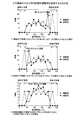
そこで、画像取得特性調整部12dは、図4に示すように、算出したコード領域の各ブロックの階調レベルから、その分布を求め、全ブロックの個数のうち予め決められた所定の割合が不感領域に含まれている場合には、不感領域に含まれるブロックが減少するように入力機器の入出力特性(明るさ、コントラスト)の設定値を調整する。 Therefore, as shown in FIG. 4, the image acquisition characteristic adjusting unit 12d obtains the distribution from the calculated gradation level of each block of the code area, and the predetermined percentage of the total number of blocks is insensitive. If it is included in the area, the set value of the input / output characteristics (brightness, contrast) of the input device is adjusted so that the blocks included in the insensitive area are reduced.
ここで、カメラの入出力特性調整の調整例について、図5を用いて説明する。画像取得特性調整部12dは、明側の不感帯にのみブロックが含まれており、その数がβ個以上の場合には、全体が明るくなって不感帯から出るようにカメラの明るさ調整パラメータを1段階変更する(図5(1)参照)。 Here, an adjustment example of the input / output characteristic adjustment of the camera will be described with reference to FIG. The image acquisition characteristic adjusting unit 12d includes a block only in the bright side dead zone, and when the number is β or more, the brightness adjustment parameter of the camera is set to 1 so that the whole is brightened and comes out of the dead zone. The stage is changed (see FIG. 5 (1)).
また、画像取得特性調整部12dは、暗側の不感帯にのみブロックが含まれており、その数がβ個以上の場合には、全体が暗くなって不感帯から出るように、カメラの明るさ調整パラメータを1段階変更する(図5(2)参照)。また、画像取得特性調整部12dは、明側および暗側の不感帯の両方にブロックが含まれており、その数の和がβ個以上の場合には、基準階調レベルの分布が両者の間に集まって不感帯から出るように、カメラのコントラスト調整パラメータを1段階変更する(図5(3)参照)。 Further, the image acquisition characteristic adjusting unit 12d includes a block only in the dark side dead zone, and when the number is β or more, the brightness adjustment of the camera is performed so that the whole is dark and comes out of the dead zone. The parameter is changed by one step (see FIG. 5 (2)). Further, the image acquisition characteristic adjusting unit 12d includes blocks in both the bright side and the dark side dead zone, and when the sum of the numbers is β or more, the distribution of the reference gradation level is between the two. The contrast adjustment parameters of the camera are changed by one step so that they come out of the dead zone (see FIG. 5 (3)).
[デコード処理装置による処理]
次に、図6を用いて、実施例1に係るデコード処理装置10による処理を説明する。図6は、実施例1に係るデコード処理装置10の処理動作を示すフローチャートである。[Processing by decoding processor]
Next, processing performed by the
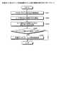
同図に示すように、デコード処理装置10の画像取得部12aは、ユーザによってアプリケーションが起動されると(ステップS101肯定)、入力機器11によって撮影された画像の画像データを取得する(ステップS102)。続いて、デコード処理部12bは、画像データのコード埋め込み領域を抽出して求め(ステップS103)、コード埋め込み領域をブロックに分割して各ブロックの階調レベルを求め(ステップS104)、各ブロックの階調レベルから埋め込まれているコードを算出する(ステップS105)。 As shown in the figure, when the application is started by the user (Yes in step S101), the image acquisition unit 12a of the
そして、デコード結果判定部12cは、デコード処理部12bによって行われたデコード処理が成功したか否かを判定する(ステップS106)。その結果、デコード結果判定部12cは、デコードに成功した場合には(ステップS106肯定)、その時の画像サイズの設定値および入出力特性の設定値を設定パラメータ記憶部13aに保存する(ステップS107)。 Then, the decoding
また、デコード処理が成功しなかったと判定された場合には(ステップS106否定)、画像取得特性調整部12dは、画像データ取得時の画像取得特性(視野範囲の設定値、入出力特性の設定値)を調整する処理として、画像サイズ調整処理(後に図7を用いて詳述)を行い(ステップS108)、画像入出力特性調整処理(後に図8を用いて詳述)を行って(ステップS109)、ステップS102に戻る。その後、調整された画像取得特性で入力機器11が画像を撮影する。 If it is determined that the decoding process has not been successful (No at step S106), the image acquisition characteristic adjusting unit 12d determines that the image acquisition characteristic (view range setting value, input / output characteristic setting value) at the time of image data acquisition is obtained. ) Is performed (step S108) and image input / output characteristic adjustment processing (detailed later using FIG. 8) is performed (step S109). ), The process returns to step S102. Thereafter, the
ここで、図7を用いて、実施例1に係るデコード処理装置10による画像サイズ調整処理を説明する。図7は、実施例1に係るデコード処理装置のズーム値の調整処理を示すフローチャートである。 Here, the image size adjustment processing by the
同図に示すように、画像取得特性調整部12dは、コード埋め込み領域を抽出し(ステップS201)、そのコード埋め込み領域の大きさを算出して(ステップS202)、コード埋め込み領域の大きさと予め決定している適正サイズとなる大きさとを比較する(ステップS203)。 As shown in the figure, the image acquisition characteristic adjusting unit 12d extracts a code embedding area (step S201), calculates the size of the code embedding area (step S202), and determines the size of the code embedding area in advance. The size that is the appropriate size is compared (step S203).
そして、画像取得特性調整部12dは、コード埋め込み領域が適正サイズの範囲内である場合には(ステップS204肯定)、画像サイズ調整処理を終了する。一方、画像取得特性調整部12dは、コード埋め込み領域が適正サイズの範囲で無い場合には(ステップS204否定)、ズームの設定値を変更し、適正サイズの範囲内となるように調整を行って(ステップS205)、画像サイズ調整処理を終了する。 When the code embedding area is within the appropriate size range (Yes at Step S204), the image acquisition characteristic adjustment unit 12d ends the image size adjustment process. On the other hand, if the code embedding area is not in the appropriate size range (No in step S204), the image acquisition characteristic adjusting unit 12d changes the zoom setting value and adjusts it to be within the appropriate size range. (Step S205), the image size adjustment process is terminated.
ここで、図8を用いて、実施例1に係るデコード処理装置10による画像入出力特性調整処理を説明する。図8は、実施例1に係るデコード処理装置の入出力特性の調整処理を示すフローチャートである。 Here, the image input / output characteristic adjustment processing by the
同図に示すように、画像取得特性調整部12dは、ステガノグラフィが埋め込まれている長方形領域を抽出し(ステップS301)、この領域を縦n個×横m個のブロックに分割する(ステップS302)。そして、画像取得特性調整部12dは、各ブロックの基準階調レベルを算出し(ステップS303)、各ブロックの基準階調レベルの頻度ヒストグラムを作成する(ステップS304)。 As shown in the figure, the image acquisition characteristic adjustment unit 12d extracts a rectangular area in which steganography is embedded (step S301), and divides this area into n vertical blocks × m horizontal blocks (step S302). . Then, the image acquisition characteristic adjusting unit 12d calculates the reference gradation level of each block (step S303), and creates a frequency histogram of the reference gradation level of each block (step S304).
続いて、画像取得特性調整部12dは、頻度ヒストグラムより、明側および暗側の不感帯に属するブロックの数bをカウントする(ステップS305)。そして、画像取得特性調整部12dは、不感帯に属するブロックの数bが不感帯に属してもよいブロック数の上限βより少ないかを判定する(ステップS306)。 Subsequently, the image acquisition characteristic adjusting unit 12d counts the number b of blocks belonging to the bright and dark dead zones from the frequency histogram (step S305). Then, the image acquisition characteristic adjusting unit 12d determines whether the number b of blocks belonging to the dead zone is smaller than the upper limit β of the number of blocks that may belong to the dead zone (step S306).
その結果、画像取得特性調整部12dは、不感帯に属するブロックの数bが不感帯に属してもよいブロック数の上限βより少ない場合には(ステップS306肯定)、画像入出力特性調整処理を終了する。一方、画像取得特性調整部12dは、不感帯に属するブロックの数bが不感帯に属してもよいブロック数の上限β以上である場合には(ステップS306否定)、この数が小さくなるように入力機器11の入出力特性の設定値の調整を行う(ステップS307)。 As a result, when the number b of blocks belonging to the dead zone is smaller than the upper limit β of the number of blocks that may belong to the dead zone (Yes at step S306), the image acquisition characteristic adjusting unit 12d ends the image input / output characteristic adjusting process. . On the other hand, when the number b of blocks belonging to the dead zone is equal to or larger than the upper limit β of the number of blocks that may belong to the dead zone (No at step S306), the image acquisition characteristic
[実施例1の効果]
上述してきたように、デコード処理装置10は、デコード処理の結果に応じて、撮影画像中のコード埋め込み領域の大きさや、入力機器の階調レベルの入出力特性を調整しながらデコード処理を行い、従来の固定設定値を用いたまま撮影を行った場合にはデコードできなかった印刷画像や撮影条件でのデコード成功率が向上する結果、取得画像データの画質を適正化して、デコード性能を向上することが可能である。[Effect of Example 1]
As described above, the
また、実施例1によれば、入力機器からの画像データから抽出したコード埋め込み領域の大きさが所定の範囲に満たないもしくは所定の範囲より大きい場合には、所定の範囲内になるように入力機器の視野範囲(ズーム)の設定値を変更する結果、次回のデコード時にはコード埋め込み領域の大きさが適正サイズに近づき、デコード成功率を向上することが可能である。 Further, according to the first embodiment, when the size of the code embedding area extracted from the image data from the input device is less than the predetermined range or larger than the predetermined range, the input is performed within the predetermined range. As a result of changing the setting value of the visual field range (zoom) of the device, the size of the code embedding area approaches the appropriate size at the next decoding, and the decoding success rate can be improved.
また、実施例1によれば、算出したコード領域の各ブロックの階調レベルからその分布を求め、全ブロックの個数のうち予め決められた所定の割合が不感領域に含まれている場合には、不感領域に含まれるブロックが減少するように入力機器の入出力特性(明るさ、コントラスト)の設定値を変更して次回の入力画像の取得時に用いる結果、次回のデコード時には不感領域に含まれるブロックが減少し、デコード成功率を向上することが可能である。 Further, according to the first embodiment, the distribution is obtained from the gradation level of each block of the calculated code area, and when the predetermined ratio of the total number of blocks is included in the insensitive area, As a result of changing the input / output characteristics (brightness and contrast) setting values of the input device so that the number of blocks included in the insensitive area is reduced and using it when acquiring the next input image, it is included in the insensitive area during the next decoding. It is possible to reduce the block and improve the decoding success rate.
また、実施例1によれば、デコードに成功した場合には、その時の画像データの撮影に使用した入力機器の設定値を保存し、次のデコード時に初期値として用いる。これにより、次回のデコード時にはデフォルト設定値よりも適正な設定値を用いた撮影条件からデコードを開始できる結果、デコード成功率を向上することが可能である。 Further, according to the first embodiment, when the decoding is successful, the setting value of the input device used for capturing the image data at that time is stored and used as the initial value at the next decoding. As a result, the decoding success rate can be improved as a result of starting decoding from a shooting condition using a setting value more appropriate than the default setting value at the next decoding.
さて、これまで本発明の実施例について説明したが、本発明は上述した実施例以外にも、種々の異なる形態にて実施されてよいものである。そこで、以下では実施例2として本発明に含まれる他の実施例を説明する。 Although the embodiments of the present invention have been described so far, the present invention may be implemented in various different forms other than the embodiments described above. Therefore, another embodiment included in the present invention will be described below as a second embodiment.
(1)システム構成等
図示した各装置の各構成要素は機能概念的なものであり、必ずしも物理的に図示の如く構成されていることを要しない。すなわち、各装置の分散・統合の具体的形態は図示のものに限られず、その全部または一部を、各種の負荷や使用状況などに応じて、任意の単位で機能的または物理的に分散・統合して構成することができる。例えば、画像取得部12aとデコード処理部12bを統合してもよい。さらに、各装置にて行なわれる各処理機能は、その全部または任意の一部が、CPUおよび当該CPUにて解析実行されるプログラムにて実現され、あるいは、ワイヤードロジックによるハードウェアとして実現され得る。(1) System Configuration, etc. Each component of each illustrated device is functionally conceptual and does not necessarily need to be physically configured as illustrated. In other words, the specific form of distribution / integration of each device is not limited to that shown in the figure, and all or a part thereof may be functionally or physically distributed or arbitrarily distributed in arbitrary units according to various loads or usage conditions. Can be integrated and configured. For example, the image acquisition unit 12a and the decoding processing unit 12b may be integrated. Further, all or any part of each processing function performed in each device may be realized by a CPU and a program analyzed and executed by the CPU, or may be realized as hardware by wired logic.
(2)プログラム
ところで、上記の実施例で説明した各種の処理は、あらかじめ用意されたプログラムをコンピュータで実行することによって実現することができる。そこで、以下では、図9を用いて、上記の実施例と同様の機能を有するプログラムを実行するコンピュータの一例を説明する。図9は、デコード処理プログラムを実行するコンピュータを示す図である。(2) Program By the way, various processes described in the above embodiments can be realized by executing a program prepared in advance by a computer. In the following, an example of a computer that executes a program having the same function as that of the above embodiment will be described with reference to FIG. FIG. 9 is a diagram illustrating a computer that executes a decoding processing program.
同図に示すように、デコード処理装置としてのコンピュータ600は、入力機器11、出力部20、HDD610、RAM620、ROM630およびCPU640をバス650で接続して構成される。 As shown in the figure, a
そして、ROM630には、上記の実施例と同様の機能を発揮するデコード処理プログラム、つまり、図9に示すように、画像取得プログラム631、デコード処理プログラム632、デコード結果判定プログラム633および画像取得特性調整プログラム634が予め記憶されている。なお、プログラム631〜634については、図2に示したデコード処理装置の各構成要素と同様、適宜統合または分散してもよい。 The
そして、CPU640が、これらのプログラム631〜634をROM630から読み出して実行することで、図9に示すように、各プログラム631〜634は、画像取得プロセス641、デコード処理プロセス642、デコード結果判定プロセス643、画像取得特性調整プロセス644として機能するようになる。各プロセス641〜644は、図2に示した画像取得部12a、デコード処理部12b、デコード結果判定部12c、画像取得特性調整部12dにそれぞれ対応する。 Then, the
また、HDD610には、図9に示すように、設定パラメータテーブル611が設けられる。なお、設定パラメータテーブル611は、図2に示した設定パラメータ記憶部13aに対応する。そして、CPU640は、設定パラメータテーブル611に対してデータを登録するとともに、設定パラメータテーブル611から設定パラメータデータ621を読み出してRAM620に格納し、RAM620に格納された設定パラメータデータ621に基づいて処理を実行する。 Further, the
(付記1)入力機器によって撮影された画像データを取得し、当該画像データに埋め込まれたコードのデコード処理を行うデコード処理方法をコンピュータに実行させるデコード処理プログラムであって、
コードのデコード処理が成功したか否かを判定するデコード判定手順と、
前記デコード判定手順によって前記デコード処理が成功しなかったと判定された場合には、前記画像データ取得時の画像取得特性を調整する画像取得特性調整手順と、
をコンピュータに実行させることを特徴とするデコード処理プログラム。(Supplementary note 1) A decoding processing program for acquiring image data captured by an input device and causing a computer to execute a decoding processing method for decoding a code embedded in the image data,
A decoding determination procedure for determining whether or not the decoding process of the code is successful;
If it is determined by the decoding determination procedure that the decoding process has not been successful, an image acquisition characteristic adjustment procedure for adjusting an image acquisition characteristic at the time of image data acquisition;
A decoding processing program characterized by causing a computer to execute.
(付記2)前記画像取得特性調整手順は、前記画像取得特性として、前記画像データに埋め込まれたコードの領域の大きさが所定の範囲内となるように、前記入力機器のズーム値を調整することを特徴とする付記1に記載のデコード処理プログラム。(Additional remark 2) The said image acquisition characteristic adjustment procedure adjusts the zoom value of the said input device as the said image acquisition characteristic so that the magnitude | size of the area | region of the code embedded in the said image data may become in a predetermined range. The decoding processing program according to supplementary note 1, wherein:
(付記3)前記画像取得特性調整手順は、前記画像取得特性として、前記画像データに埋め込まれたコードの領域をブロック分割し、各ブロックの階調レベルを算出し、当該階調レベルが所定範囲内にあるブロックの数が、所定の割合より小さくなるように、前記入力機器の入出力特性を調整することを特徴とする付記1に記載のデコード処理プログラム。(Additional remark 3) The image acquisition characteristic adjustment procedure divides the area of the code embedded in the image data into blocks as the image acquisition characteristic, calculates the gradation level of each block, and the gradation level is within a predetermined range. The decoding processing program according to appendix 1, wherein the input / output characteristics of the input device are adjusted so that the number of blocks in the input device is smaller than a predetermined ratio.
(付記4)前記画像取得特性調整手順によって前記画像取得特性の調整が行われた後の設定パラメータを設定パラメータ記憶部に格納する設定パラメータ記憶手順をさらにコンピュータに実行させることを特徴とする付記1〜3のいずれか一つに記載のデコード処理プログラム。(Supplementary Note 4) The computer further executes a setting parameter storage procedure for storing the setting parameter in the setting parameter storage unit after the adjustment of the image acquisition characteristic by the image acquisition characteristic adjustment procedure. The decoding process program as described in any one of -3.
(付記5)前記デコード判定手順は、前記画像取得特性調整手順によって前記画像取得特性の調整が行われた後に、コードのデコード処理が成功したか否かを再度判定することを特徴とする付記1〜4のいずれか一つに記載のデコード処理プログラム。(Additional remark 5) The said decoding determination procedure determines again whether the decoding process of the code was successful after adjusting the said image acquisition characteristic by the said image acquisition characteristic adjustment procedure, The additional remark 1 characterized by the above-mentioned. The decoding process program as described in any one of -4.
(付記6)入力機器によって撮影された画像データを取得し、当該画像データに埋め込まれたコードのデコード処理を行うデコード処理方法であって、
コードのデコード処理が成功したか否かを判定するデコード判定ステップと、
前記デコード判定ステップによって前記デコード処理が成功しなかったと判定された場合には、前記画像データ取得時の画像取得特性を調整する画像取得特性調整ステップと、
を含んだことを特徴とするデコード処理方法。(Additional remark 6) It is the decoding processing method which acquires the image data image | photographed with the input device, and decodes the code embedded in the said image data,
A decoding determination step for determining whether or not the decoding process of the code is successful;
If it is determined by the decoding determination step that the decoding process has not been successful, an image acquisition characteristic adjustment step of adjusting an image acquisition characteristic at the time of acquiring the image data;
A decoding processing method characterized by comprising:
(付記7)前記画像取得特性調整ステップは、前記画像取得特性として、前記画像データに埋め込まれたコードの領域の大きさが所定の範囲内となるように、前記入力機器のズーム値を調整することを特徴とする付記6に記載のデコード処理方法。(Appendix 7) In the image acquisition characteristic adjustment step, as the image acquisition characteristic, the zoom value of the input device is adjusted so that the size of the code area embedded in the image data is within a predetermined range. The decoding processing method according to supplementary note 6, wherein:
(付記8)前記画像取得特性調整ステップは、前記画像取得特性として、前記画像データに埋め込まれたコードの領域をブロック分割し、各ブロックの階調レベルを算出し、当該階調レベルが所定範囲内にあるブロックの数が、所定の割合より小さくなるように、前記入力機器の入出力特性を調整することを特徴とする付記6に記載のデコード処理方法。(Appendix 8) The image acquisition characteristic adjustment step divides the area of the code embedded in the image data into blocks as the image acquisition characteristic, calculates the gradation level of each block, and the gradation level is within a predetermined range. 7. The decoding processing method according to appendix 6, wherein the input / output characteristics of the input device are adjusted so that the number of blocks in the input device is smaller than a predetermined ratio.
(付記9)前記画像取得特性調整ステップによって前記画像取得特性の調整が行われた後の設定パラメータを設定パラメータ記憶部に格納する設定パラメータ記憶ステップをさらに含んだことを特徴とする付記6〜8のいずれか一つに記載のデコード処理方法。(Supplementary note 9) The supplementary notes 6 to 8, further comprising a setting parameter storage step for storing a setting parameter after the adjustment of the image acquisition characteristic in the image acquisition characteristic adjustment step in a setting parameter storage unit. The decoding processing method according to any one of the above.
(付記10)前記デコード判定ステップは、前記画像取得特性調整ステップによって前記画像取得特性の調整が行われた後に、コードのデコード処理が成功したか否かを再度判定することを特徴とする付記6〜9のいずれか一つに記載のデコード処理方法。(Additional remark 10) The said decoding determination step determines again whether the decoding process of the code was successful after the adjustment of the said image acquisition characteristic by the said image acquisition characteristic adjustment step. The decoding processing method as described in any one of -9.
(付記11)入力機器によって撮影された画像データを取得し、当該画像データに埋め込まれたコードのデコード処理を行うデコード処理装置であって、
コードのデコード処理が成功したか否かを判定するデコード判定手段と、
前記デコード判定手段によって前記デコード処理が成功しなかったと判定された場合には、前記画像データ取得時の画像取得特性を調整する画像取得特性調整手段と、
を備えたことを特徴とするデコード処理装置。(Additional remark 11) It is the decoding processing apparatus which acquires the image data image | photographed with the input device, and performs the decoding process of the code embedded in the said image data,
Decoding determination means for determining whether or not the decoding process of the code is successful;
If the decoding determination means determines that the decoding process has not been successful, an image acquisition characteristic adjusting means for adjusting an image acquisition characteristic at the time of acquiring the image data;
A decoding processing apparatus comprising:
(付記12)前記画像取得特性調整手段は、前記画像取得特性として、前記画像データに埋め込まれたコードの領域の大きさが所定の範囲内となるように、前記入力機器のズーム値を調整することを特徴とする付記11に記載のデコード処理装置。(Additional remark 12) The said image acquisition characteristic adjustment means adjusts the zoom value of the said input apparatus as the said image acquisition characteristic so that the magnitude | size of the area | region of the code embedded in the said image data may become in a predetermined range. The decoding processing apparatus according to
(付記13)前記画像取得特性調整手段は、前記画像取得特性として、前記画像データに埋め込まれたコードの領域をブロック分割し、各ブロックの階調レベルを算出し、当該階調レベルが所定範囲内にあるブロックの数が、所定の割合より小さくなるように、前記入力機器の入出力特性を調整することを特徴とする付記11に記載のデコード処理装置。(Supplementary note 13) The image acquisition characteristic adjusting means divides the code area embedded in the image data into blocks as the image acquisition characteristic, calculates the gradation level of each block, and the gradation level is within a predetermined range. The decoding processing apparatus according to
(付記14)前記画像取得特性調整手段によって前記画像取得特性の調整が行われた後の設定パラメータを設定パラメータ記憶部に格納する設定パラメータ記憶手段をさらに備えたことを特徴とする付記11〜13のいずれか一つに記載のデコード処理装置。(Supplementary note 14) The supplementary notes 11 to 13, further comprising setting parameter storage means for storing a setting parameter after the adjustment of the image acquisition characteristic by the image acquisition characteristic adjustment means in a setting parameter storage unit. The decoding processing device according to any one of the above.
(付記15)前記デコード判定手段は、前記画像取得特性調整手段によって前記画像取得特性の調整が行われた後に、コードのデコード処理が成功したか否かを再度判定することを特徴とする付記11〜14のいずれか一つに記載のデコード処理装置。(Additional remark 15) The said decoding determination means determines again whether the decoding process of the code was successful after the adjustment of the said image acquisition characteristic by the said image acquisition characteristic adjustment means. The decoding processing device according to any one of -14.
以上のように、本発明に係るデコード処理プログラム、デコード処理方法およびデコード処理装置は入力機器によって撮影された画像データを取得し、当該画像データに埋め込まれたコードのデコード処理を行う場合に有用であり、特に、取得画像データの画質を適正化して、デコード性能を向上することに適する。 As described above, the decoding processing program, the decoding processing method, and the decoding processing device according to the present invention are useful when acquiring image data captured by an input device and performing decoding processing of a code embedded in the image data. In particular, it is suitable for improving the decoding performance by optimizing the image quality of the acquired image data.
10 デコード処理装置
11 入力機器
12 制御部
12a 画像取得部
12b デコード処理部
12c デコード結果判定部
12d 画像取得特性調整部
13 記憶部
13a 設定パラメータ記憶部DESCRIPTION OF
Claims (5)
Translated fromJapanese前記画像データに埋め込まれたコードの領域をブロック分割し、各ブロックの階調レベルを取得し、前記各ブロックの階調レベルから埋め込まれているコードを算出するデコード処理が成功したか否かを判定するデコード判定手順と、
前記デコード判定手順によって隣接ブロックの階調レベル差を取得できずに、前記デコード処理が成功しなかったと判定された場合には、前記画像データに埋め込まれたコードの領域の大きさが予め決められた所定のサイズとなるように、前記入力機器のズーム値を調整した後に、前記画像データに埋め込まれたコードの領域をブロック分割し、各ブロックの階調レベルを取得し、当該階調レベルが第一のレベルよりも明るいブロックの数、および階調レベルが第二のレベルよりも暗いブロックの数が、予め決められたブロック数の上限よりも少なくなるように、前記入力機器の明るさ調整パラメータおよび/またはコントラスト調整パラメータを調整する画像取得特性調整手順と、
をコンピュータに実行させ、
前記デコード判定手順は、前記画像取得特性調整手順によって前記入力機器の明るさ調整パラメータおよび/またはコントラスト調整パラメータの調整が行われた後に、コードのデコード処理が成功したか否かを再度判定することを特徴とするデコード処理プログラム。A decoding processing program for acquiring image data captured by an input device and causing a computer to execute a decoding processing method for decoding a code embedded in the image data,
It is determined whether or notthe decoding process ofdividing the code area embedded in the image data into blocks, obtaining the gradation level of each block, and calculating the embedded code from the gradation level of each block is successful. A decoding determination procedure for determining;
When it is determined that the decoding process has not succeeded becausethe gradation level difference between adjacent blocks cannot be acquired by the decoding determination procedure,the size of the code area embedded in the image data is determined in advance. After adjusting the zoom value of the input device so as to have a predetermined size, the code area embedded in the image data is divided into blocks, and the gradation level of each block is obtained. Adjusting the brightness of the input device so that the number of blocks brighter than the first level and the number of blocks whose gradation level is darker than the second level are less than the predetermined upper limit of the number of blocks. Image acquisition characteristic adjustment procedure for adjustingparameters and / or contrast adjustment parameters ;
To the computer,
The decoding determination procedure determines again whether or not the code decoding process has succeeded after the brightness adjustment parameter and / or the contrast adjustment parameter of the input device have been adjusted by the image acquisition characteristic adjustment procedure. A decoding processing program characterized by
前記画像データに埋め込まれたコードの領域をブロック分割し、各ブロックの階調レベルを取得し、前記各ブロックの階調レベルから埋め込まれているコードを算出するデコード処理が成功したか否かを判定するデコード判定ステップと、
前記デコード判定ステップによって隣接ブロックの階調レベル差を取得できずに、前記デコード処理が成功しなかったと判定された場合には、前記画像データに埋め込まれたコードの領域の大きさが予め決められた所定のサイズとなるように、前記入力機器のズーム値を調整した後に、前記画像データに埋め込まれたコードの領域をブロック分割し、各ブロックの階調レベルを取得し、当該階調レベルが第一のレベルよりも明るいブロックの数、および階調レベルが第二のレベルよりも暗いブロックの数が、予め決められたブロック数の上限よりも少なくなるように、前記入力機器の明るさ調整パラメータおよび/またはコントラスト調整パラメータを調整する画像取得特性調整ステップと、
前記画像取得特性調整ステップによって前記入力機器の明るさ調整パラメータおよび/またはコントラスト調整パラメータの調整が行われた後に、前記デコード処理が成功したか否かを再度判定する再度デコード判定ステップと、
を含んだことを特徴とするデコード処理方法。A decoding processing method for acquiring image data photographed by an input device and performing decoding processing of a code embedded in the image data,
It is determined whether or notthe decoding process ofdividing the code area embedded in the image data into blocks, obtaining the gradation level of each block, and calculating the embedded code from the gradation level of each block is successful. A decoding determination step for determining;
If the decoding determination stepcannot acquire the gradation level difference between adjacent blocks and it is determined that the decoding process has not succeeded, the size of the code area embedded in the image data is determined in advance. After adjusting the zoom value of the input device so as to have a predetermined size, the code area embedded in the image data is divided into blocks, and the gradation level of each block is obtained. Adjusting the brightness of the input device so that the number of blocks brighter than the first level and the number of blocks whose gradation level is darker than the second level are less than the predetermined upper limit of the number of blocks. An image acquisition characteristic adjustment step for adjusting theparameters and / or contrast adjustment parameters ;
Decoding determination step for re-determining whether or not the decoding process has succeeded after the adjustment of the brightness adjustment parameter and / or the contrast adjustment parameter of the input device by the image acquisition characteristic adjustment step;
A decoding processing method characterized by comprising:
前記画像データに埋め込まれたコードの領域をブロック分割し、各ブロックの階調レベルを取得し、前記各ブロックの階調レベルから埋め込まれているコードを算出するデコード処理が成功したか否かを判定するデコード判定手段と、
前記デコード判定手段によって隣接ブロックの階調レベル差を取得できずに、前記デコード処理が成功しなかったと判定された場合には、前記画像データに埋め込まれたコードの領域の大きさが予め決められた所定のサイズとなるように、前記入力機器のズーム値を調整した後に、前記画像データに埋め込まれたコードの領域をブロック分割し、各ブロックの階調レベルを取得し、当該階調レベルが第一のレベルよりも明るいブロックの数、および階調レベルが第二のレベルよりも暗いブロックの数が、予め決められたブロック数の上限よりも少なくなるように、前記入力機器の明るさ調整パラメータおよび/またはコントラスト調整パラメータを調整する画像取得特性調整手段と、
を備え、
前記デコード判定手段は、前記画像取得特性調整手段によって前記入力機器の明るさ調整パラメータおよび/またはコントラスト調整パラメータの調整が行われた後に、コードのデコード処理が成功したか否かを再度判定することを特徴とするデコード処理装置。A decoding processing device that acquires image data captured by an input device and decodes a code embedded in the image data,
It is determined whether or notthe decoding process ofdividing the code area embedded in the image data into blocks, obtaining the gradation level of each block, and calculating the embedded code from the gradation level of each block is successful. Decoding determination means for determining;
When it is determined that the decoding determination unitcannot acquire the gradation level difference between adjacent blocks and the decoding process is not successful, the size of the code area embedded in the image data is determined in advance. After adjusting the zoom value of the input device so as to have a predetermined size, the code area embedded in the image data is divided into blocks, and the gradation level of each block is obtained. Adjusting the brightness of the input device so that the number of blocks brighter than the first level and the number of blocks whose gradation level is darker than the second level are less than the predetermined upper limit of the number of blocks. Image acquisition characteristic adjusting means for adjustingparameters and / or contrast adjustment parameters ;
Equipped witha,
The decoding determination unit determines again whether or not the code decoding process has succeeded after the brightness adjustment parameter and / or the contrast adjustment parameter of the input device have been adjusted by the image acquisition characteristic adjustment unit. A decoding processing device characterized by the above.
Priority Applications (1)
| Application Number | Priority Date | Filing Date | Title |
|---|---|---|---|
| JP2007255194AJP4918903B2 (en) | 2007-09-28 | 2007-09-28 | Decoding processing program, decoding processing method, and decoding processing apparatus |
Applications Claiming Priority (1)
| Application Number | Priority Date | Filing Date | Title |
|---|---|---|---|
| JP2007255194AJP4918903B2 (en) | 2007-09-28 | 2007-09-28 | Decoding processing program, decoding processing method, and decoding processing apparatus |
Publications (2)
| Publication Number | Publication Date |
|---|---|
| JP2009088923A JP2009088923A (en) | 2009-04-23 |
| JP4918903B2true JP4918903B2 (en) | 2012-04-18 |
Family
ID=40661768
Family Applications (1)
| Application Number | Title | Priority Date | Filing Date |
|---|---|---|---|
| JP2007255194AActiveJP4918903B2 (en) | 2007-09-28 | 2007-09-28 | Decoding processing program, decoding processing method, and decoding processing apparatus |
Country Status (1)
| Country | Link |
|---|---|
| JP (1) | JP4918903B2 (en) |
Families Citing this family (1)
| Publication number | Priority date | Publication date | Assignee | Title |
|---|---|---|---|---|
| CN104228369B (en)* | 2014-08-25 | 2017-01-18 | 沈阳东软医疗系统有限公司 | Printing method and device |
Family Cites Families (3)
| Publication number | Priority date | Publication date | Assignee | Title |
|---|---|---|---|---|
| JP2005026848A (en)* | 2003-06-30 | 2005-01-27 | Toppan Printing Co Ltd | Digital watermark parameter setting device, digital watermark parameter setting method, and digital watermark parameter setting program |
| JPWO2006115128A1 (en)* | 2005-04-21 | 2008-12-18 | 松下電器産業株式会社 | Digital watermark detection device, method, program, and integrated circuit device |
| JP4134128B2 (en)* | 2005-09-26 | 2008-08-13 | 富士通株式会社 | Encoding availability determination device, encoding availability determination method, and encoding availability determination program |
- 2007
- 2007-09-28JPJP2007255194Apatent/JP4918903B2/enactiveActive
Also Published As
| Publication number | Publication date |
|---|---|
| JP2009088923A (en) | 2009-04-23 |
Similar Documents
| Publication | Publication Date | Title |
|---|---|---|
| CN108335279B (en) | Image fusion and HDR imaging | |
| JP5414841B2 (en) | Face detection method | |
| US9077913B2 (en) | Simulating high dynamic range imaging with virtual long-exposure images | |
| CN109829859B (en) | Image processing method and terminal equipment | |
| JP6505237B2 (en) | Image processing device | |
| US10382671B2 (en) | Image processing apparatus, image processing method, and recording medium | |
| WO2015184208A1 (en) | Constant bracketing for high dynamic range operations (chdr) | |
| JP2009212853A (en) | White balance controller, its control method, and imaging apparatus | |
| CN105007430B (en) | The method and apparatus set for determining exposure | |
| US8780215B2 (en) | Apparatus and method for processing an image to correct image distortion caused by a hand shake | |
| CN116438594B (en) | Image brightness adjustment method, image brightness adjustment device, and electronic equipment | |
| JP4851505B2 (en) | Image processing apparatus and image processing method | |
| US8165421B2 (en) | Method and apparatus for image processing by using stored image | |
| JP4841582B2 (en) | Image correction program and image correction apparatus | |
| JP7699964B2 (en) | Imaging device, control method thereof, program, and storage medium | |
| JP4918903B2 (en) | Decoding processing program, decoding processing method, and decoding processing apparatus | |
| US8849066B2 (en) | Image processing apparatus, image processing method, and storage medium | |
| CN100401749C (en) | Image processing device and method | |
| CN110072050B (en) | Self-adaptive adjustment method and device of exposure parameters and shooting equipment | |
| JP4527439B2 (en) | Image processing method, apparatus, and program | |
| CN110971825A (en) | Image correction method, electronic device and storage medium | |
| JP2011221337A (en) | Electronic camera | |
| JP2012205031A (en) | Image signal processing apparatus | |
| JP5398860B2 (en) | Image processing apparatus, image processing apparatus control method, program, and storage medium | |
| JP2007174015A (en) | Image management program and image management apparatus |
Legal Events
| Date | Code | Title | Description |
|---|---|---|---|
| A621 | Written request for application examination | Free format text:JAPANESE INTERMEDIATE CODE: A621 Effective date:20100517 | |
| A977 | Report on retrieval | Free format text:JAPANESE INTERMEDIATE CODE: A971007 Effective date:20110628 | |
| A131 | Notification of reasons for refusal | Free format text:JAPANESE INTERMEDIATE CODE: A131 Effective date:20110705 | |
| A521 | Written amendment | Free format text:JAPANESE INTERMEDIATE CODE: A523 Effective date:20110902 | |
| TRDD | Decision of grant or rejection written | ||
| A01 | Written decision to grant a patent or to grant a registration (utility model) | Free format text:JAPANESE INTERMEDIATE CODE: A01 Effective date:20120104 | |
| A01 | Written decision to grant a patent or to grant a registration (utility model) | Free format text:JAPANESE INTERMEDIATE CODE: A01 | |
| A61 | First payment of annual fees (during grant procedure) | Free format text:JAPANESE INTERMEDIATE CODE: A61 Effective date:20120117 | |
| R150 | Certificate of patent or registration of utility model | Ref document number:4918903 Country of ref document:JP Free format text:JAPANESE INTERMEDIATE CODE: R150 Free format text:JAPANESE INTERMEDIATE CODE: R150 | |
| FPAY | Renewal fee payment (event date is renewal date of database) | Free format text:PAYMENT UNTIL: 20150210 Year of fee payment:3 |