JP4917538B2 - Disposable pneumatic safety syringe with retractable needle - Google Patents
Disposable pneumatic safety syringe with retractable needleDownload PDFInfo
- Publication number
- JP4917538B2 JP4917538B2JP2007528545AJP2007528545AJP4917538B2JP 4917538 B2JP4917538 B2JP 4917538B2JP 2007528545 AJP2007528545 AJP 2007528545AJP 2007528545 AJP2007528545 AJP 2007528545AJP 4917538 B2JP4917538 B2JP 4917538B2
- Authority
- JP
- Japan
- Prior art keywords
- needle
- plunger
- syringe
- downstream
- gas
- Prior art date
- Legal status (The legal status is an assumption and is not a legal conclusion. Google has not performed a legal analysis and makes no representation as to the accuracy of the status listed.)
- Expired - Fee Related
Links
- 239000003814drugSubstances0.000claimsabstractdescription113
- 238000002347injectionMethods0.000claimsabstractdescription54
- 239000007924injectionSubstances0.000claimsabstractdescription54
- 238000011144upstream manufacturingMethods0.000claimsdescription198
- 229940079593drugDrugs0.000claimsdescription99
- 238000003860storageMethods0.000claimsdescription40
- 238000007789sealingMethods0.000claimsdescription12
- 230000004888barrier functionEffects0.000claimsdescription10
- 231100000252nontoxicToxicity0.000claimsdescription8
- 230000003000nontoxic effectEffects0.000claimsdescription8
- 230000002093peripheral effectEffects0.000claimsdescription8
- 238000013459approachMethods0.000claimsdescription7
- 230000006378damageEffects0.000claimsdescription4
- 239000013013elastic materialSubstances0.000claimsdescription3
- 230000004044responseEffects0.000claimsdescription3
- 230000009972noncorrosive effectEffects0.000claimsdescription2
- 210000004204blood vesselAnatomy0.000claims1
- 239000007789gasSubstances0.000description216
- 210000004027cellAnatomy0.000description124
- 238000013461designMethods0.000description27
- 239000012528membraneSubstances0.000description26
- 239000000463materialSubstances0.000description24
- 239000012530fluidSubstances0.000description18
- 210000003813thumbAnatomy0.000description14
- 230000001681protective effectEffects0.000description12
- 238000004519manufacturing processMethods0.000description10
- 230000008901benefitEffects0.000description9
- 230000007246mechanismEffects0.000description9
- 210000003811fingerAnatomy0.000description7
- 230000013011matingEffects0.000description7
- 230000006835compressionEffects0.000description5
- 238000007906compressionMethods0.000description5
- 238000006073displacement reactionMethods0.000description5
- 238000000034methodMethods0.000description5
- 238000006243chemical reactionMethods0.000description4
- 238000010304firingMethods0.000description4
- 230000006870functionEffects0.000description4
- 208000012266Needlestick injuryDiseases0.000description3
- 230000008859changeEffects0.000description3
- 230000006872improvementEffects0.000description3
- 238000005304joiningMethods0.000description3
- 239000004033plasticSubstances0.000description3
- 230000002441reversible effectEffects0.000description3
- 239000000243solutionSubstances0.000description3
- IJGRMHOSHXDMSA-UHFFFAOYSA-NAtomic nitrogenChemical compoundN#NIJGRMHOSHXDMSA-UHFFFAOYSA-N0.000description2
- 208000035473Communicable diseaseDiseases0.000description2
- 239000004743PolypropyleneSubstances0.000description2
- 230000009471actionEffects0.000description2
- 239000000853adhesiveSubstances0.000description2
- 230000001070adhesive effectEffects0.000description2
- 210000001124body fluidAnatomy0.000description2
- 239000010839body fluidSubstances0.000description2
- 239000004088foaming agentSubstances0.000description2
- 238000003780insertionMethods0.000description2
- 230000037431insertionEffects0.000description2
- 239000007788liquidSubstances0.000description2
- 239000000314lubricantSubstances0.000description2
- 239000000203mixtureSubstances0.000description2
- 238000004806packaging method and processMethods0.000description2
- 230000002028prematureEffects0.000description2
- 239000000376reactantSubstances0.000description2
- 239000000126substanceSubstances0.000description2
- 239000002699waste materialSubstances0.000description2
- LVGUZGTVOIAKKC-UHFFFAOYSA-N1,1,1,2-tetrafluoroethaneChemical compoundFCC(F)(F)FLVGUZGTVOIAKKC-UHFFFAOYSA-N0.000description1
- 235000010585Ammi visnagaNutrition0.000description1
- 244000153158Ammi visnagaSpecies0.000description1
- 238000012356Product developmentMethods0.000description1
- 238000009825accumulationMethods0.000description1
- 238000004026adhesive bondingMethods0.000description1
- 230000003466anti-cipated effectEffects0.000description1
- 210000002421cell wallAnatomy0.000description1
- 230000008878couplingEffects0.000description1
- 238000010168coupling processMethods0.000description1
- 238000005859coupling reactionMethods0.000description1
- 230000001419dependent effectEffects0.000description1
- 230000001066destructive effectEffects0.000description1
- 238000010586diagramMethods0.000description1
- 238000007599dischargingMethods0.000description1
- 238000005553drillingMethods0.000description1
- 238000001647drug administrationMethods0.000description1
- 238000005516engineering processMethods0.000description1
- 238000011156evaluationMethods0.000description1
- 239000006260foamSubstances0.000description1
- 208000015181infectious diseaseDiseases0.000description1
- 230000003993interactionEffects0.000description1
- 238000010255intramuscular injectionMethods0.000description1
- 239000007927intramuscular injectionSubstances0.000description1
- 239000002184metalSubstances0.000description1
- 238000012986modificationMethods0.000description1
- 230000004048modificationEffects0.000description1
- 229910052757nitrogenInorganic materials0.000description1
- 230000000149penetrating effectEffects0.000description1
- 238000005498polishingMethods0.000description1
- 229920001155polypropylenePolymers0.000description1
- 230000008569processEffects0.000description1
- 238000011160researchMethods0.000description1
- 230000000241respiratory effectEffects0.000description1
- 230000000717retained effectEffects0.000description1
- 239000007787solidSubstances0.000description1
- 229910001220stainless steelInorganic materials0.000description1
- 239000010935stainless steelSubstances0.000description1
Images


Classifications
- A—HUMAN NECESSITIES
- A61—MEDICAL OR VETERINARY SCIENCE; HYGIENE
- A61M—DEVICES FOR INTRODUCING MEDIA INTO, OR ONTO, THE BODY; DEVICES FOR TRANSDUCING BODY MEDIA OR FOR TAKING MEDIA FROM THE BODY; DEVICES FOR PRODUCING OR ENDING SLEEP OR STUPOR
- A61M5/00—Devices for bringing media into the body in a subcutaneous, intra-vascular or intramuscular way; Accessories therefor, e.g. filling or cleaning devices, arm-rests
- A61M5/178—Syringes
- A61M5/31—Details
- A61M5/32—Needles; Details of needles pertaining to their connection with syringe or hub; Accessories for bringing the needle into, or holding the needle on, the body; Devices for protection of needles
- A61M5/3205—Apparatus for removing or disposing of used needles or syringes, e.g. containers; Means for protection against accidental injuries from used needles
- A61M5/321—Means for protection against accidental injuries by used needles
- A61M5/322—Retractable needles, i.e. disconnected from and withdrawn into the syringe barrel by the piston
- A—HUMAN NECESSITIES
- A61—MEDICAL OR VETERINARY SCIENCE; HYGIENE
- A61M—DEVICES FOR INTRODUCING MEDIA INTO, OR ONTO, THE BODY; DEVICES FOR TRANSDUCING BODY MEDIA OR FOR TAKING MEDIA FROM THE BODY; DEVICES FOR PRODUCING OR ENDING SLEEP OR STUPOR
- A61M5/00—Devices for bringing media into the body in a subcutaneous, intra-vascular or intramuscular way; Accessories therefor, e.g. filling or cleaning devices, arm-rests
- A61M5/178—Syringes
- A61M5/20—Automatic syringes, e.g. with automatically actuated piston rod, with automatic needle injection, filling automatically
- A61M5/2046—Media being expelled from injector by gas generation, e.g. explosive charge
- A—HUMAN NECESSITIES
- A61—MEDICAL OR VETERINARY SCIENCE; HYGIENE
- A61M—DEVICES FOR INTRODUCING MEDIA INTO, OR ONTO, THE BODY; DEVICES FOR TRANSDUCING BODY MEDIA OR FOR TAKING MEDIA FROM THE BODY; DEVICES FOR PRODUCING OR ENDING SLEEP OR STUPOR
- A61M5/00—Devices for bringing media into the body in a subcutaneous, intra-vascular or intramuscular way; Accessories therefor, e.g. filling or cleaning devices, arm-rests
- A61M5/178—Syringes
- A61M5/31—Details
- A61M5/315—Pistons; Piston-rods; Guiding, blocking or restricting the movement of the rod or piston; Appliances on the rod for facilitating dosing ; Dosing mechanisms
- A61M5/31501—Means for blocking or restricting the movement of the rod or piston
- A61M5/31505—Integral with the syringe barrel, i.e. connected to the barrel so as to make up a single complete piece or unit
- A—HUMAN NECESSITIES
- A61—MEDICAL OR VETERINARY SCIENCE; HYGIENE
- A61M—DEVICES FOR INTRODUCING MEDIA INTO, OR ONTO, THE BODY; DEVICES FOR TRANSDUCING BODY MEDIA OR FOR TAKING MEDIA FROM THE BODY; DEVICES FOR PRODUCING OR ENDING SLEEP OR STUPOR
- A61M5/00—Devices for bringing media into the body in a subcutaneous, intra-vascular or intramuscular way; Accessories therefor, e.g. filling or cleaning devices, arm-rests
- A61M5/178—Syringes
- A61M5/31—Details
- A61M5/315—Pistons; Piston-rods; Guiding, blocking or restricting the movement of the rod or piston; Appliances on the rod for facilitating dosing ; Dosing mechanisms
- A61M5/31565—Administration mechanisms, i.e. constructional features, modes of administering a dose
- A61M5/3159—Dose expelling manners
- A61M5/31591—Single dose, i.e. individually set dose administered only once from the same medicament reservoir, e.g. including single stroke limiting means
- A—HUMAN NECESSITIES
- A61—MEDICAL OR VETERINARY SCIENCE; HYGIENE
- A61M—DEVICES FOR INTRODUCING MEDIA INTO, OR ONTO, THE BODY; DEVICES FOR TRANSDUCING BODY MEDIA OR FOR TAKING MEDIA FROM THE BODY; DEVICES FOR PRODUCING OR ENDING SLEEP OR STUPOR
- A61M5/00—Devices for bringing media into the body in a subcutaneous, intra-vascular or intramuscular way; Accessories therefor, e.g. filling or cleaning devices, arm-rests
- A61M5/178—Syringes
- A61M5/31—Details
- A61M5/32—Needles; Details of needles pertaining to their connection with syringe or hub; Accessories for bringing the needle into, or holding the needle on, the body; Devices for protection of needles
- A61M5/3205—Apparatus for removing or disposing of used needles or syringes, e.g. containers; Means for protection against accidental injuries from used needles
- A61M5/321—Means for protection against accidental injuries by used needles
- A61M5/322—Retractable needles, i.e. disconnected from and withdrawn into the syringe barrel by the piston
- A61M5/3234—Fully automatic needle retraction, i.e. in which triggering of the needle does not require a deliberate action by the user
- A—HUMAN NECESSITIES
- A61—MEDICAL OR VETERINARY SCIENCE; HYGIENE
- A61M—DEVICES FOR INTRODUCING MEDIA INTO, OR ONTO, THE BODY; DEVICES FOR TRANSDUCING BODY MEDIA OR FOR TAKING MEDIA FROM THE BODY; DEVICES FOR PRODUCING OR ENDING SLEEP OR STUPOR
- A61M5/00—Devices for bringing media into the body in a subcutaneous, intra-vascular or intramuscular way; Accessories therefor, e.g. filling or cleaning devices, arm-rests
- A61M5/178—Syringes
- A61M5/31—Details
- A61M5/32—Needles; Details of needles pertaining to their connection with syringe or hub; Accessories for bringing the needle into, or holding the needle on, the body; Devices for protection of needles
- A61M5/3293—Needles; Details of needles pertaining to their connection with syringe or hub; Accessories for bringing the needle into, or holding the needle on, the body; Devices for protection of needles characterised by features of the needle hub
- A—HUMAN NECESSITIES
- A61—MEDICAL OR VETERINARY SCIENCE; HYGIENE
- A61M—DEVICES FOR INTRODUCING MEDIA INTO, OR ONTO, THE BODY; DEVICES FOR TRANSDUCING BODY MEDIA OR FOR TAKING MEDIA FROM THE BODY; DEVICES FOR PRODUCING OR ENDING SLEEP OR STUPOR
- A61M5/00—Devices for bringing media into the body in a subcutaneous, intra-vascular or intramuscular way; Accessories therefor, e.g. filling or cleaning devices, arm-rests
- A61M5/50—Devices for bringing media into the body in a subcutaneous, intra-vascular or intramuscular way; Accessories therefor, e.g. filling or cleaning devices, arm-rests having means for preventing re-use, or for indicating if defective, used, tampered with or unsterile
- A61M5/5013—Means for blocking the piston or the fluid passageway to prevent illegal refilling of a syringe
- A61M5/502—Means for blocking the piston or the fluid passageway to prevent illegal refilling of a syringe for blocking the piston
- A—HUMAN NECESSITIES
- A61—MEDICAL OR VETERINARY SCIENCE; HYGIENE
- A61M—DEVICES FOR INTRODUCING MEDIA INTO, OR ONTO, THE BODY; DEVICES FOR TRANSDUCING BODY MEDIA OR FOR TAKING MEDIA FROM THE BODY; DEVICES FOR PRODUCING OR ENDING SLEEP OR STUPOR
- A61M5/00—Devices for bringing media into the body in a subcutaneous, intra-vascular or intramuscular way; Accessories therefor, e.g. filling or cleaning devices, arm-rests
- A61M5/50—Devices for bringing media into the body in a subcutaneous, intra-vascular or intramuscular way; Accessories therefor, e.g. filling or cleaning devices, arm-rests having means for preventing re-use, or for indicating if defective, used, tampered with or unsterile
- A61M5/508—Means for preventing re-use by disrupting the piston seal, e.g. by puncturing
- A—HUMAN NECESSITIES
- A61—MEDICAL OR VETERINARY SCIENCE; HYGIENE
- A61M—DEVICES FOR INTRODUCING MEDIA INTO, OR ONTO, THE BODY; DEVICES FOR TRANSDUCING BODY MEDIA OR FOR TAKING MEDIA FROM THE BODY; DEVICES FOR PRODUCING OR ENDING SLEEP OR STUPOR
- A61M5/00—Devices for bringing media into the body in a subcutaneous, intra-vascular or intramuscular way; Accessories therefor, e.g. filling or cleaning devices, arm-rests
- A61M5/178—Syringes
- A61M5/20—Automatic syringes, e.g. with automatically actuated piston rod, with automatic needle injection, filling automatically
- A61M2005/2073—Automatic syringes, e.g. with automatically actuated piston rod, with automatic needle injection, filling automatically preventing premature release, e.g. by making use of a safety lock
- A—HUMAN NECESSITIES
- A61—MEDICAL OR VETERINARY SCIENCE; HYGIENE
- A61M—DEVICES FOR INTRODUCING MEDIA INTO, OR ONTO, THE BODY; DEVICES FOR TRANSDUCING BODY MEDIA OR FOR TAKING MEDIA FROM THE BODY; DEVICES FOR PRODUCING OR ENDING SLEEP OR STUPOR
- A61M5/00—Devices for bringing media into the body in a subcutaneous, intra-vascular or intramuscular way; Accessories therefor, e.g. filling or cleaning devices, arm-rests
- A61M5/178—Syringes
- A61M5/31—Details
- A61M2005/3123—Details having air entrapping or venting means, e.g. purging channels in pistons
- A—HUMAN NECESSITIES
- A61—MEDICAL OR VETERINARY SCIENCE; HYGIENE
- A61M—DEVICES FOR INTRODUCING MEDIA INTO, OR ONTO, THE BODY; DEVICES FOR TRANSDUCING BODY MEDIA OR FOR TAKING MEDIA FROM THE BODY; DEVICES FOR PRODUCING OR ENDING SLEEP OR STUPOR
- A61M5/00—Devices for bringing media into the body in a subcutaneous, intra-vascular or intramuscular way; Accessories therefor, e.g. filling or cleaning devices, arm-rests
- A61M5/178—Syringes
- A61M5/31—Details
- A61M5/32—Needles; Details of needles pertaining to their connection with syringe or hub; Accessories for bringing the needle into, or holding the needle on, the body; Devices for protection of needles
- A61M5/3205—Apparatus for removing or disposing of used needles or syringes, e.g. containers; Means for protection against accidental injuries from used needles
- A61M5/321—Means for protection against accidental injuries by used needles
- A61M5/322—Retractable needles, i.e. disconnected from and withdrawn into the syringe barrel by the piston
- A61M5/3234—Fully automatic needle retraction, i.e. in which triggering of the needle does not require a deliberate action by the user
- A61M2005/3241—Needle retraction energy is accumulated inside of a hollow plunger rod
- A61M2005/3242—Needle retraction by vacuum
Landscapes
- Health & Medical Sciences (AREA)
- Engineering & Computer Science (AREA)
- Hematology (AREA)
- Anesthesiology (AREA)
- Biomedical Technology (AREA)
- Heart & Thoracic Surgery (AREA)
- Vascular Medicine (AREA)
- Life Sciences & Earth Sciences (AREA)
- Animal Behavior & Ethology (AREA)
- General Health & Medical Sciences (AREA)
- Public Health (AREA)
- Veterinary Medicine (AREA)
- Environmental & Geological Engineering (AREA)
- Infusion, Injection, And Reservoir Apparatuses (AREA)
Abstract
Description
Translated fromJapanese【技術分野】
【0001】
本発明は、一般に、皮下注射針と共に使用するタイプの空気圧式安全注射器に関する。本発明による注射器では、注射器の使用後にプランジャが注射器本体(筒)内にロックされ且つ針がプランジャの格納内腔に格納され、それにより使用後の不注意による突き刺しや筒からのプランジャの望ましくない再伸出が防止される。針の格納は、加圧ガスの放出や他の適切な空気圧手段によって実現され、例えば、ガスセルを破裂させたりガスを放出する化学反応を引き起こさせたりすることによって成し遂げられる。この一般的なタイプの注射器は、「格納式注射器」と呼ばれることがある。この用語は、針が注射器の本体内に格納されることを意味する。
【背景技術】
【0002】
多くの危険な伝染病が感染者の体液との接触によって広がることはよく知られている。注射器の使用後に、残留体液が注射器針の上や中に残る可能性が高い。そのため、注射器は、一般に、使い捨てされるように設計されている。使用後に安全に取り扱うために、注射器の針は、例えば処分のために注射器を回収している人に針が間違って突き刺さり、その人に残留体液が注入されるのを防ぐためにカバーされなければならない。一般に、注射器は保護キャップを備え、注射器の使用後にその保護キャップをを使って針の先端を覆うことができる。しかしながら、使用済みの針にキャップをしようとする人がキャップをなくし、間違って自分に突き刺し、その結果伝染病に感染することが時々起こっている。更に、使い捨て用に設計された針や注射器を共用したり再使用したりする麻薬常用者によって、伝染病や危険な病気が蔓延する。
【0003】
これまで使用後に注射器内に針を格納するための機構を注射器に組み込むことによってこの問題に対処する幾つかの試みがあった。米国特許第5,334,155号(Sobel、1994年8月2日)は、真空にした二重壁保護シースを有する針ガードを開示している。使用前に保護シース内をある程度真空にすることによってシースが内側に折りたたまれ、その結果、針が保護シースから突出し、注射に使用できるようになる。注射後に、保護シースの二重壁の一箇所を破って保護シースの内部を大気圧にすることができる。次に保護シースが拡張して突出している針を覆う。しかしながら、この保護シースは、針を患者に刺す箇所の視界を遮ることがあるので、注射器を使いにくくする場合がある。更に、ユーザは、注射後に、二重壁を破ってシースを作動させるために注射器上のユーザの手の位置を変更しなければならないため不便である。このように、安全機構は、薬剤の注射後に自動的に作動しない。
【0004】
米国特許第5,188,614号(Hart、1993年2月23日)に示した保護安全装置は、注射器を包囲する中空円筒ケーシングである。ケーシングの下流端に二成分発泡剤が配置される。注射後に、二成分発泡剤の2つの成分が混合され、ケーシング内に注射器を強制的に後退させ針を包囲する膨脹発泡混合物ができる。しかしながら、この装置は、ケーシングが従来の注射器をぴったりと覆うように設計されており、装置のサイズと感触が従来の注射器と異なっているので、注射をする際にケーシングが注射器の使用のじゃまになる場合があるという欠点を有する。更に、保護シースを作成するためにかなりの量の材料を必要とし、装置の製造と破棄の両方のコストが高くなる。
【0005】
米国特許第6,193,695号(Rippstein、2001年2月27日)は、プランジャヘッドの上流側に真空室を備えた安全注射器を開示している。薬剤の注射後に、プランジャヘッドが針頭部と係合し、針頭部の外部の周囲大気圧が針頭部に働き、針とプランジャが真空に抗して注射器本体に強制的に押し込まれる。次に、ユーザがプランジャアームをポキッと折り取って針を更に使用できなくすることができる。この装置は、ユーザがプランジャアームが折り取らなかった場合に、針が間違って再伸出する可能性があるという欠点を有する。この装置の更に他の欠点は、ユーザが一定の射出力(injection force)を加えないと、薬剤が完全に注射される前にプランジャが真空下で後退し、それにより注射器が逆方向に動作する可能性があることである。
【0006】
米国特許第6,413,236号(Van Dyke、2002年7月2日)は、プランジャヘッドの上流側に真空室を備えた安全注射器を開示している。薬剤の注射後に、プランジャヘッドが針頭部と係合し、針頭部の外部の周囲大気圧が針頭部に働き、針とプランジャが真空に抗して注射器本体内に強制的に押し込まれる。この特許では、米国特許第6,193,695号と対照的に、針は注射器本体内に斜めに収容され、それにより針の突き刺し端が注射器の内側面に押し当てられて、プランジャアームが注射器本体の外に完全に拡張されている場合でも針の再伸出が防止される。しかしながら、この装置は、ユーザが一定の射出力を加えないと、薬剤が完全に注射される前にプランジャが真空下で後退し、それにより注射器が逆方向に動作する可能性があるという欠点を解決できていない。
【0007】
米国特許第5,868,713号(Klippenstein、1999年2月9日)に開示された装置は、これ以前の注射器技術を超える著しい改良を具現化している。この初期のKlippenstein注射器は、無毒圧縮ガスを含むガス溜め部を備えている。このガス溜め部は、針用ヘッダを下流方向に強制的に押したときに針用ヘッダによって破られ、放出した無毒圧縮ガスが、針用ヘッダとプランジャを付勢して上流に摺動させ、針を注射器本体内に格納する上流方向の付勢圧力を提供する。針の格納後に、ロック機構がプランジャの下流方向への動きを防ぐ。しかしながら、格納段階の終わりで、プランジャは注射器の筒の外部に向けて拡張し続け、従って、ユーザは、プランジャの端部にある親指ボタンから親指を離すことにより手の位置を変更しなければならなかった。更に、格納後にプランジャがロック拡張位置に保持されるので、拡張された注射器は、従来の注射器よりも廃棄容器内のスペースをとる。本発明の目的は、この従来のKlippenstein設計と関連した以上その他の欠点を克服することである。
【0008】
注射器を注射に使用した後の不注意の針の突き刺しを防ぐ問題に対する最適な解決策を提供するように設計された注射器は、以下の特徴を有することになる。
1.注射器機構は、比較的単純、即ち、その設計目的に適合する範囲で可能な限り少数の可動部品で作成されなければならず、また好ましくは従来の注射器と同様の外観と感触を有し、簡単に操作できなければならない。
2.注射器機構は、使用後に針を確実に格納するか針を別の方法で確実に覆って、不注意の突き刺しを防ぐようにしなければならない。
3.注射器は、製造が比較的安価でなければならない。
4.注射器の使用後に破棄する廃プラスチックや他の材料が最少でなければならない。
5.安全に関連する手段が、ユーザの手における注射器の感触を大幅に変えるものであってはならない。
6.針が格納又は遮蔽された後で、信頼性の高い安全装置によって針が再び露出するのが防止されなければならない。
なお、構造と操作の単純さ(上記の目的1)は、上記の他の5つの目的の達成に貢献することに注意されたい。
【先行技術文献】
【特許文献】
【0009】
【特許文献1】
米国特許第5118614号明細書
【特許文献2】
米国特許第5120310号明細書
【特許文献3】
米国特許第5122118号明細書
【特許文献4】
米国特許第5176640号明細書
【特許文献5】
米国特許第5188614号明細書
【特許文献6】
米国特許第5211628号明細書
【特許文献7】
米国特許第5224936号明細書
【特許文献8】
米国特許第5334155号明細書
【特許文献9】
米国特許第5389076号明細書
【特許文献10】
米国特許第5407436号明細書
【特許文献11】
米国特許第5423758号明細書
【特許文献12】
米国特許第5433712号明細書
【特許文献13】
米国特許第5533970号明細書
【特許文献14】
米国特許第5575777号明細書
【特許文献15】
米国特許第5578011号明細書
【特許文献16】
米国特許第5632733号明細書
【特許文献17】
米国特許第5702367号明細書
【特許文献18】
米国特許第5797880号明細書
【特許文献19】
米国特許第5868713号明細書
【特許文献20】
米国特許第5989220号明細書
【特許文献21】
米国特許第6015438号明細書
【特許文献22】
米国特許第6083199号明細書
【特許文献23】
米国特許第6086568号明細書
【特許文献24】
米国特許第6090077号明細書
【特許文献25】
米国特許第6099500号明細書
【特許文献26】
米国特許第6179812号明細書
【特許文献27】
米国特許第6183440号明細書
【特許文献28】
米国特許第6193695号明細書
【特許文献29】
米国特許第6206853号明細書
【特許文献30】
米国特許第6210371号明細書
【特許文献31】
米国特許第6221055号明細書
【特許文献32】
米国特許第6241707号明細書
【特許文献33】
米国特許第6267749号明細書
【特許文献34】
米国特許第6361525号明細書
【特許文献35】
米国特許第6409701号明細書
【特許文献36】
米国特許第6413236号明細書
【特許文献37】
米国特許第6413237号明細書
【特許文献38】
米国特許第6432087号明細書
【特許文献39】
米国特許第6458105号明細書
【特許文献40】
米国特許第6474472号明細書
【特許文献41】
米国特許第6494863号明細書
【特許文献42】
米国特許第6558357号明細書
【特許文献43】
米国特許第6572565号明細書
【特許文献44】
米国特許第6572584号明細書
【特許文献45】
米国特許第6585690号明細書
【特許文献46】
米国特許第6599268号明細書
【特許文献47】
米国特許第6679863号明細書
【特許文献48】
米国特許第6692470号明細書
【特許文献49】
米国特許第6740062号明細書
【特許文献50】
米国特許第6767335号明細書
【特許文献51】
米国特許第6846301号明細書
【特許文献52】
米国特許第6868713号明細書
【特許文献53】
米国特許第6872193号明細書
【特許文献54】
米国特許第7090656号明細書
【特許文献55】
米国特許第7182734号明細書
【特許文献56】
米国特許第7258678号明細書
【特許文献57】
米国特許第7294118号明細書
【特許文献58】
米国特許第7344517号明細書
【特許文献59】
米国特許第7351224号明細書
【特許文献60】
米国特許出願公開第2003/0040717号明細書
【特許文献61】
米国特許出願公開第2003/0078540号明細書
【特許文献62】
米国特許出願公開第2003/0176843号明細書
【特許文献63】
米国特許出願公開第2004/0153034号明細書
【特許文献64】
米国特許出願公開第2005/0159705号明細書
【特許文献65】
米国特許出願公開第2005/0159707号明細書
【特許文献66】
米国特許出願公開第2005/0215951号明細書
【特許文献67】
欧州特許出願公開第0479217号明細書
【特許文献68】
オランダ国特許出願公開第9000292号明細書
【特許文献69】
国際公開第91/04760号
【特許文献70】
国際公開第99/25401号
【特許文献71】
国際公開第2001/080930号
【特許文献72】
国際公開第2004/082747号
【特許文献73】
国際公開第2005/011792号
【特許文献74】
国際公開第2005/070292号
【特許文献75】
国際公開第2005/072801号
【特許文献76】
国際公開第2006/017889号
【特許文献77】
国際公開第2006/108243号
【特許文献78】
国際公開第2006/119570号
【非特許文献】
【0010】
【非特許文献1】
Maxxon Applauds New Federal Needlestick Act Press Release, Nov. 2, 2000, Business Wire
【非特許文献2】
Maxxon Safety Syringe Press Release, Feb. 2000, online: <http://www.micro-stocks.com/Research/MXON.htm>
【非特許文献3】
Maxxon Announces Safety Syringe Patent Filing, ADVANCE For Respiratory Care Practitioners, Daily News Watch, Feb. 2000, online: <http://www.advanceforrcp.com/previousdnw/rcdnwjan31.html>
【発明の開示】
【課題を解決するための手段】
【0011】
本発明の主な目的は、薬剤の注射完了後に、針がプランジャの格納内腔内に自動的に格納され且つプランジャが注射器本体(筒)内にロックされる、皮下注射針と共に使用するタイプの注射器を提供することである。更に他の目的は、米国特許第5,868,713号に開示された先行技術のKlippenstein注射器を含む先行技術の注射器設計と関連した欠点を除去又は軽減することである。
【0012】
本発明による安全注射器は、注射器筒、プランジャ、及び注射器内で針を組み立てる手段を有する。(針は、選択された設計により、完全な組立体の一部であるか、後で取り付けられる。)本発明による注射器の全体的構造の特徴及び動作特性は、本明細書で述べる内容以外は、先行技術の設計のものとほぼ類似している。先行技術の注射器と異なる本発明の注射器の主な特徴の例は、以下の通りである。
a.筒内で軸方向に移動可能なプランジャは、注射器の使用後に針を収容するために、遠位端が開いた軸方向に延在する格納内腔を備える。この内腔は、格納後に針先端がプランジャ内腔内に留まるように、針と後述する針搬送体を組み合わせた長さを受け入れるのに十分な寸法に決められる。
b.組み立てられた注射器内のプランジャの遠位側にガス放出セルが配置される。ガス放出セルは(例示した好ましい実施形態では、加圧ガスを収容し、本明細書ではガスセルと呼ばれることがある)、プランジャの下流方向への動きによる薬剤の注射が実質的に完了するまで完全な状態のままであり機能しない。後で詳述する好ましい実施形態で使用する場合、ガスセルは、注射器内に個別に組み込まれ、適切に選択された無毒で非腐食性の加圧ガスを収容する個別の独立した構成要素であることが好ましい。ガスセルは、ガスを放出するように破裂可能であることが好ましいが、その代りに、最初に分離されており、注射の実質的な完了後に制御可能に混合されて加圧ガスを放出する化学反応を引き起こす化学成分を含んでもよい。
c.組み立てられた注射器内のプランジャの遠位側に配置されたガス放出トリガ手段は、プランジャが下流方向移動端に近づいたときのプランジャの下流方向への動きに応じて、ガス放出セルに注射器内部にガスを放出させるように動作可能である。本明細書に示した好ましい実施形態では、個別の破裂可能なガスセルと共に使用するために、ガス放出トリガ手段は、突き刺しランスを備えた穿孔器を有することが好ましいが、その代りに、ガスセルの壁を破るための引き裂き又は押しつぶし手段を備えてもよい。混合したときに化学反応を起こして加圧ガスを放出する別個の化学成分をそれぞれ収容する2隔室セル等の代替のガス放出セルを使用する場合、ガス放出トリガは、例えば、実質的に注射完了後に2つの隔室間の隔壁を破り、次にこれと同時か又は好ましくはその少し後でガス放出セルの外部壁を破る手段を備えることができる。
d.針の近位端近くで針に針搬送体が結合される。この針搬送体は、プランジャ内腔内で軸方向に移動可能であり、加圧ガスが作用する遠位側受け面を有する。針搬送体は、プランジャ内腔の内側壁と摩擦状態で係合する。また針搬送体は、ガス圧力の下でプランジャ内腔内に移動して針を運び、針を内腔内に格納する。(当然ながら、ガスが針搬送体に到達できる適切な流路がなければならない。場合により、針搬送体の受け面に加圧ガスが急激に作用すること防ぐために流路を絞ることが望ましいことがある。)針は、その近位端に針ヘッダを備えるように形成されてもよく、針の近位端又はその近くに配置された針用ヘッダに他の方法で固定されてもよい。そのような後者の例の針搬送体は、針用ヘッダに固定されてもよく結合されてもよい。針搬送体は、内腔の壁と摺動可能に係合する封止要素を備えることが好ましい。好ましい一実施形態では内腔が遠位端で絞られているので、そのような実施形態の封止要素は、内腔の絞られた遠位部分から上流に移動した後で、内腔の大きな径の部分の壁と密接するように径が弾力的に膨脹可能でなければならない。
e.加圧ガスの上流に許容レベルのガス封止を提供できる設計の針搬送体の他に、針が完全に格納される前に注射器からガスが不要に漏れるのを防ぐか又は遅らせるために更に他の一個以上のガス障壁が設けられる。ガス障壁の少なくとも幾つかは、嵌合する構成要素間の適切な滑りばめ又は絞りばめによって実現することができる。場合によって、部品の摺動可能な係合は、重大なガスの損失を防ぐのに十分に密である。また、これらの障壁の幾つかは、薬剤が注射器から不要に漏れるのを阻止する働きをする。目的は、当然ながら、(i)注射器内の実質的に全ての薬剤を患者に注射し且つ注射器からの漏れをなくすことと、(ii)注射後に針搬送体をガス圧力でプランジャ内腔に押し込んで針を完全に格納し且つ注射器操作の針格納段階が完了するまで加圧ガスを放散させないことである。
f.針を内腔に格納した後で針が下流に移動するのを防止又は妨害するための針再出現障壁を設けることが好ましい。
【0013】
当然ながら、本発明の創意に富む特徴を注射器に組み込むことによって、注射器の主な機能(すなわち、筒に薬剤を吸い込んで薬剤を患者に注射すること)があまり妨げられてはならない。このため、例えば、注射器筒に薬剤を充填し薬剤を患者に注射する際には、針と針搬送体の内腔内への上流方向の動きを阻止しなければならない。選択される特定の注射器設計によるが、プランジャ上の摩擦と手の圧力によって前述の目的をほとんど完全に達成することができる。
【0014】
本発明による注射器設計のどの実施態様におけるガス流路、ガス圧力に反応する構成要素と表面、並びにガス及び液体遮断要素の設計も、薬剤の損失や漏れの可能性がほとんどなく且つ注射器の通常の外観と感触をほとんど妨げることなく、正常な薬剤充填段階と正常な薬剤注射段階の操作を可能にするのに有効でなければならない。前述の目的は、多くの種類の注射器設計に共通なものであり、本説明を利用することよって有能な注射器設計者は誰でも容易に取り組むことができるはずである。本発明による注射器は、針をプランジャ内腔に押し込むがプランジャを筒から上流方向に押し出さない操作の針格納段階でガス圧力が有効であるように設計されなければならないことに注意されたい。このため、針は、ガス圧力に応じて動く可動要素に取り付け又は結合されなければならなず、その可動要素と針は両方とも、ガス圧力の下で自由にプランジャ内腔に入り上流に移動できなければならない。可動要素が上流に押動されるとき、針は必然的に可動要素と一緒に移動する。更に、注射器は、ガス放出セルから放出されたガスが可動要素に達して可動要素に有効な上流方向の力を加えることができるように設計されなければならない。針を格納する際、プランジャの上流方向への動きは、ユーザの手の圧力だけではなく注射器の構成部品の相互作用又は係合によって妨害されるはずである。注射器から針用の穴を通る下流方向へのガスの漏れは、無駄で非効率的であり、針を格納している間、防止又は妨害しなければならない。針を格納した後、針がプランジャ内腔から再出現するのを阻止しなければならない。
【0015】
本発明の好ましい実施形態の主要な利点の幾つかを実現するために、本発明による注射器は、また、注射器の使用後に筒からプランジャが不要に再伸出するのを妨害又は防止するためのプランジャロックを備える。プランジャロックは、プランジャに固定されたプランジャ係合要素と、筒に固定されプランジャ係合要素と係合する係合要素とを有する。これらの係合要素は、プランジャの下流方向移動端の近くで互いに係合接触するように配置される。プランジャが係合接触位置よりも更に下流に移動すると、プランジャは、プランジャの下流方向移動端又はその近くで注射器内にロックされる。ロック前にプランジャが不要にガスで押されて上流に移動するのを防ぐために、プランジャロックは、プランジャ下流方向移動経路においてガス放出トリガ手段が作動してガス放出セルにガスを放出させる位置の少し上流の位置でプランジャを筒にロックするように構成されてもよい。しかしながら、プランジャをその下流方向端まで押す操作は、通常、連続的な手の動きで行われるので、プランジャロックが破裂より前に起こるか破裂と実質的に同時に起こるか、或いは破裂がプランジャロックより少し前に起こるかに関係なく、プランジャの動きの量は、通常、プランジャを筒にロックしガス放出セルを破るのに十分である。
【0016】
本発明による注射器は、針が内腔に格納された後で針が下流方向に動くのを防止又は妨害するために、針がプランジャ内に格納された後で針の先端の下流に配置された針再出現障壁を備えてもよい。この障壁は、好ましくは適切な針用ポート密閉手段でよい。
【0017】
本発明の注射器の幾つかの好ましい実施形態では、筒はその内部が、ガス放出セルとガス放出トリガ手段を収容するための小さい下流室と、注射する薬剤を収容するための上流室とに分割され、前記室は、上流室から薬剤を針内に排出し且つ注射後に針をプランジャ内腔に収容するための軸方向の穴を有する半径方向の室分割壁によって分離されている。
【0018】
前述の実施形態における本発明の注射器は、更に、下流室内に、下流室の内側周囲壁と摺動可能且つ摩擦状態で係合し中を軸方向に移動可能な係合リングを備えてもよい。係合リングは、故意に加えられた力を受けない限り、下流室内で相対的に不動でなければならない。係合リングは、ガス放出セルと半径方向分割壁の間に配置されると共に中央開口を有する。この中央開口を介して上流室から針に薬剤が流れ込み、また、注射後に針がこの中央開口を通過してプランジャ内腔に入る。係合リングは、ガス放出トリガ手段によるガスセルの破裂を容易にするためにガスセルを閉じ込める緩衝要素を提供する。係合リングは、針用ヘッダと係合して針用ヘッダを支持し、下流室内での針と針用ヘッダの位置合わせを容易にする。プランジャの遠位端は、プランジャの下流方向移動端近くで係合リングの上流端と係合し、プランジャが下流方向に動き終わったときガス放出セルをガス放出トリガ手段に押し付けて破裂させることが好ましい。
【0019】
第1の例示的実施形態
本発明の一実施形態では、使い捨て空気圧式針格納安全注射器は、使用後の不注意による針の突き刺しの危険を減少させるために、注射器筒、及び筒内に動作可能に又は部分的に配置された以下の構成要素を含んでいる:中空の内部が格納内腔を画定する中空プランジャ、針用ポートシール、針を保持するための針用ヘッダ、中央に軸方向の開口を有する摺動可能で移動可能な円筒状物体(以後、後述する理由のために「係合リング」と呼ぶ場合もある)、ガスセル、穿孔器、及びプランジャロック。注射器筒は、中空であり、上流筒開口と、上流筒開口と軸方向反対側の下流筒開口とを備える。プランジャは、注射器筒の内部と嵌合するように寸法と形状が決定され、注射器筒内で軸方向に移動するように取り付けられる。プランジャは、プラグを収容するプラグ用開口を有し注射器筒の上流開口から突出する上流プランジャ端と、下流プランジャ端とを有する。下流プランジャ端の径は、プランジャ筒の長さのほとんどの部分の径より細い。プランジャ端の内径は、注射段階で針用ポートシールが下流プランジャ端部内に滑りばめするように選択される。
【0020】
注射後の格納段階で、針用ポートシールは、後で更に詳しく述べるように、プランジャの下流方向移動行程の終わりでのガスセルからの加圧ガスの放出によって、プランジャの格納内腔内で上流方向に押動される。針用ポートシールは、プランジャの下流端の内側面と摩擦状態で係合し、それにより薬剤を投与する際に薬剤が針用ポートシールを通って格納内腔に漏れるのを防ぐ。プランジャ内の格納内腔は、針用ポートシール、上流プランジャ端、及びプランジャの内側面によって画定される。プラグ用開口は、注射器の構成部品の組み立てを容易にするために、組み立て中に注射器の内部部品に届くように工具の挿入を可能にする開口を提供する。注射器の組み立て後、プランジャプラグは、プラグ用開口にパチンと嵌め込まれ、それによりプランジャの格納内腔が密閉される。摺動可能なプランジャシールが下流プランジャ端部を取り囲み取り付けられる。プランジャシールの寸法と材料は、プランジャシールが、注射器筒の内側面と摺動可能に接触し、(i)薬剤がプランジャシールを通過して漏れるのを防ぎ、同時に(ii)プランジャが長手方向に移動できるように選択される。
【0021】
移動可能な係合リングは、注射器筒の内側面と摺動可能であるが摩擦のある状態で係合し、プランジャシールの下流に配置される。係合リングは、注射器筒の内部と嵌合するように寸法と形状が決定され、また注射器筒内での制限された軸方向変位ができるように位置決めされる。このため、注射器筒の内部は、プランジャの細い下流端が十分に通ることができる大きさの中央開口を備えた室分割壁で分離された長い方の上流室と短い方の下流室に軸方向に分割される。下流室内の上流から下流に、(i)中央開口内において穿孔器ネック部と針用ヘッダ本体を係合状態で取り囲む係合リングと、(ii)ガスセルと、(iii)穿孔器本体及び先端がガスセルに向いた突き刺しランスとが配置されている。
【0022】
係合リングは、注射段階が終わるまで室分割壁に隣接する初期の静止位置から移動されず、注射段階が終わった後で、プランジャに加えられるユーザの手の圧力によって、プランジャが軸方向下流に動き続け、その結果、プランジャの下流端が係合リングに当たり、係合リングが軸方向下流に強制的に押動される。注射後のこの係合リングの移動によってガスセルが下流に移動され、それにより隣り合う穿孔器とガスセルが互いに強制的に接触させられ、最終的に穿孔器によってガスセルが破られ、その結果、この説明で更に詳しく別記されるように、ガスセルに蓄積された圧縮ガスが放出され、針が強制的に格納内腔に格納される。
【0023】
中空針用ヘッダは、係合リングの中央開口に取り付けられる。針用ヘッダの径は、組み立て中に針用ヘッダを係合リングの内側開口に押し込むことによって針用ヘッダと係合リングの間に圧縮シールが作成され、それにより係合リングと針用ヘッダの間を通って薬剤が係合リングの下流に漏れるのを防ぐように選択される。中空針が、針用ヘッダの下流端に接合されるか又は他の方法で取り付けられる。注射器に薬剤が充填されたとき、薬剤は、注射器筒内で、プランジャシールと針用ポートシールの下流で係合リングと針用ヘッダの上流に閉じ込められる。本発明の一実施形態では、針用ヘッダは、針用ヘッダの上流部分が、係合リングの中央開口から上流側に突出するように係合リング内に配置される。
【0024】
係合リングは、次のような幾つかの目的を達成する。
(a)注射器筒の周囲円筒壁と係合することによって、安定性を提供し、また望ましくない不要な流体の流れを妨げる圧縮シールを提供する。
(b)中央の軸方向開口を針用ヘッダと係合させることによって、患者に薬剤を注射する間、針用ヘッダと針を適所に保持する。
(c)中央の軸方向開口を穿孔器ネック部と係合させ、そのネック部を針用ヘッダと係合させることによって、穿孔器によるガスセルの早すぎる穿孔を防ぐ。
(d)以上の係合によって、ガスセルと穿孔器の半径方向の位置合わせを容易にし、ガスセルの突き刺しランスに対しての位置決めも容易にし、その結果プランジャの下流方向移動行程の終わりでのガスセルの最適な穴あけを容易にする。
(e)針用ポートシールと針用ヘッダの正確な位置合わせを容易にし、その結果、針用ポートシールと針用ヘッダの正確な接続を容易にして、針の正確な格納を容易にする。
(f)プランジャの下流方向移動行程の終わりでのガスセルとの係合とガスセルの変位によって、ガスセルが穿孔器まで下流方向に動いて接触し破裂し、圧縮ガスが放出され、それにより針組立体がプランジャの格納内腔に格納される。
【0025】
この実施形態では、圧縮ガスを収容する環状ガスセルは、注射器筒内の係合リングの下流に取り付けられる。ガスセルは、注射器筒内にぴったりと嵌るように寸法と形状が決定される。ガスセルの下流に穿孔器が取り付けられる。穿孔器は、係合リングの下流の注射器筒の内側面に接合されるか又は他の方法で取り付けられてもよく、或いは注射器の下流筒開口に接合されるか又は他の方法で取り付けられた針穴マウントに接合される又は他の方法で取り付けられてもよい。穿孔器は、一個以上の突き刺しランス、ネック部、及び内側開口を有する。突き刺しランスは、突き刺しランスが穿孔器からガスセルに向かって上流方向に突出するように穿孔器に取り付けられる。穿孔器のネック部は、ネック部が、穿孔器からガスセルの環状の穴を通って係合リングの内側開口に突出し、それにより針用ヘッダと接触するように取り付けられる。穿孔器のネック部は、針用ヘッダ、ガスセル及び突き刺しランスの正確な位置合わせを可能にし、針用ヘッダと針が下流方向に動くのを防ぐ。穿孔器の向きは、必要に応じて、突き刺しランスが下流に配置されたガスセルに向かって下流側に突出するように逆にされてもよい。
【0026】
穿孔器マウントは、針穴と針膜を備え、針膜は針用ポート閉鎖部として働く。針は、穿孔器の内側開口を通って針膜から突出し、針穴から下流側に突出するように取り付けられる。針膜は、針穴マウントの針穴とそのまわりに固定され、針膜が針と接触する軸に対して約30度でテーパが付けられることが好ましい。針が格納されられた後、針膜は、針穴を覆って針が針穴から再伸出するのを妨げる。針穴マウントは、針カバーに接合されるか又は他の方法で取り付けられる。この針カバーは、使用前に針の保護シースを提供し、注射器の使用前に針穴マウントからねじり取られるか、パチンと折り取られるか、又は他の方法で取り外され、その結果針が使用できるように露出される。針カバー、穿孔器マウント、及び穿孔器は、個別の部品として製造されてもよく、1個の部品として製造されてもよい。1個の部品の場合は、使用前に穿孔器を破損させずに穿孔器マウントから針カバーをねじり取るか切り離すことができなければならない。
【0027】
操作する際、注射器に薬剤を充填した後で、ユーザがプランジャに射出力を加えると、プランジャの下流端にあるプランジャシールが、注射器筒内のプランジャシールと係合リングの間に収容された薬剤に下流方向の付勢圧力をかける。ユーザによってプランジャに加えられるこの下流方向の付勢圧力は、薬剤を針の上流吸込口から針の下流先端を介して患者に注入するのに十分である。係合リングを注射器筒の内側面に固定する解除可能な摩擦力は、薬剤が針の上流吸込口に通されるときに薬剤によって係合リングにかかる下流方向の付勢圧力に対抗する。
【0028】
実質的に全ての薬剤が患者に注入されたときに、プランジャを更に下流に動かすことにより、下流プランジャ端部に配置された針用ポートシールが針用ヘッダを封止し、その結果、針の上流吸込口から患者に薬剤や他の流体がそれ以上送り込まれなくなる。ユーザによってプランジャに加えられる下流方向の力(注射後力)は、係合リングを注射器の内側面に固定する解除可能な摩擦力に打ち勝ち、それにより、係合リングを、手の圧力で注射器筒内を軸方向下流に摺動することができる。しかしながら、針用ヘッダの下流方向への動きは、針用ヘッダと接触する穿孔器のネック部によって制限される。針用ヘッダが、穿孔器の上流に突出する穿孔器のネック部と接触するとき、針用ヘッダの更なる下流方向への動きが阻止される。プランジャに注射後力を引き続き加えることにより、係合リングが軸方向下流に摺動しガスセルと接触する。その後、ガスセルが下流に移動し、最終的にガスセルが穿孔器の突き刺しランスに当たる。突き刺しランスはガスセルを破り、その結果、ガスセルから無毒圧縮ガスが、注射器筒の穿孔器、係合リング及び針用ポートシールによって囲まれた領域内に放出される。
【0029】
放出された圧縮ガスは、注射器筒内に閉じ込められる。この目的は、ガスセルの上流の注射器筒内に、針用ポートシールと下流プランジャ端部の間の摩擦力に打ち勝つのに十分な上流方向の付勢圧力を提供することである。上流方向の付勢圧力は、針用ポートシールを上流側に摺動させ、プランジャの格納内腔内に入れる。このように針用ポートシールが上流に動いている間、針用ポートシールは、針に接合されるか又は他の方法で固定された針用ヘッダに結合されたままであり、それにより針は格納内腔に格納される。放出ガスは、圧力がかかったままであり、これに対応して針用ポートシールに働く上流方向の付勢圧力を生成し、針用ポートシール、針用ヘッダ及び針を付勢してプランジャの格納内腔内で上流に摺動させ、それにより、格納内腔内に針が格納される。
【0030】
これに対応するプランジャの上流への動きは、プランジャがその下流方向端に達したときに係合してプランジャを注射器筒内にロックするプランジャロックによって防止又は阻止される。好ましい実施形態では、円周方向のプランジャ突条部が、薄い下流側と急峻な上流側を有するように構成される。その結果、プランジャに下流方向の力が加えられたときに、プランジャロックの薄い下流側が、注射器筒の上流筒開口の下流に摺動する。この上流筒開口は、プランジャの外径より僅かに小さい径のものである。ガスセルが破られて圧縮ガスが放出されたときに圧縮ガスの放出によって生じる上流方向の付勢圧力は、プランジャ突条部の急峻な上流側を強制的に注射器筒の上流筒開口を超えて上流に動かすのに不十分である。縁の下流側が薄いので、プランジャは上流筒開口を比較的容易に通過して下流方向に滑動することができる。
【0031】
ガスセル内には、上流方向の付勢圧力が、針用ポートシールを必要な距離だけ上流に移動させるのに十分な力を生成できる加圧ガスが存在していなければならない。製造前プロトタイプとして評価用に設計された注射器では、ガスセル内のガス圧力の標準値は、約5〜約20p.s.i.gの範囲であると予想され、この圧力は、約9p.s.i.gを超えないことが好ましい。針格納の速度と信頼性は、選択されるガス圧力に極めて依存することに注意されたい。従って、経験的手法を取らなければならない。ガス圧力は、針を比較的迅速に格納するのに十分でなければならないが、破裂時のガス放出によってユーザや注射器の構成部品が必要以上に衝撃を受けたり、針の格納によって体液が飛び散ることがあってはならない。これらの目的は、特に針格納がばね作用によって達成されていた従来の設計と対照的に、本発明により構成された注射器で容易に達成可能である。
【0032】
注射器のほとんどの構成部品はプラスチック材料で製造されることが好ましい。針用ポートシール、係合リング及びプランジャシールは、ゴム等から製造されることが好ましい。何故なら、注射器筒より柔軟な材料で作成される場合、これらの部品がより適切に機能するためである。注射器内の全てのゴム部品は、業界で一般に使用されるような医療用潤滑液で被覆される。一般に、針は、ステンレス鋼又は特殊な硬くて頑強なプラスチック材料で作成される。
【0033】
本発明の以上の注射器の実施形態は、容量1、1.5、2、3、5、10、20mLの注射器を含むがこれらに限定されない多くの容量サイズの注射器に適応することができる。
【0034】
第2の例示的実施形態
本発明の第2の実施形態では、注射器は、前述の本発明の第1の例示的実施形態より大きな変更点がいくつかある。詳細には、係合リングは、針用ヘッダの上流端を含む針用ヘッダを、針用ヘッダの上流端が係合リングの上流端と面一になるように、係合リングの中央円筒開口内に配置できるように変更され延長されている。更に、針用ポートシールは、最初に、針用ポートシールの下流端がプランジャの下流端部の下流方向端と面一になるようにプランジャの下流端部に取り付けられる。これらの変更は、第1の実施形態と比べて、注射器操作の注射後段階で針用ポートシールと針用ヘッダの位置合わせをより適切にでき、その結果、針用ポートシールと針用ヘッダの間の結合機構が第1の実施形態よりも精密になる。
【0035】
この第2の実施形態では、プランジャロックは、第1の実施形態のプランジャロックとほぼ同じように機能するが、ロック要素として注射器筒の上流筒開口を使用する代わりに、筒の内側面に、プランジャの外側円筒面上の突条部と設計が似ているが逆の向きに傾斜した円周方向突条部が設けられている。2つの突条部は、プランジャがその下流方向端に達する直前に互いに係合するように位置決めされる。そのロック位置での2つの突条部の肩部と肩部との間の係合は、注射器に加えられるほとんど全ての大きな破壊力に対して安全である。
【0036】
第3の例示的実施形態
本発明の第3の注射器の実施例では、穿孔器は、ガスセルの下流に配置されて穿孔器からガスセルに向かって上流方向に突出する突き刺しランスを備えるのではなく、下流プランジャ端部に取り付けられ、下流プランジャ端部からガスセルに向かって下流方向に突出する突き刺しランスを有する。
【0037】
係合円盤が、プランジャの下流端部内に配置され、薬剤を患者に注射している間に薬剤がプランジャの格納内腔に入るのを防ぐ。係合円盤の下流端に針用ポートシールが固定される。更に、ヘッダロックが係合円盤に固定され、係合リングから下流に突出する。図示した実施形態では、ヘッダロックは、針用ヘッダを掴むかえしを備えた突出するかえし付きランスを有する。係合円盤がプランジャ内に収まるとき、係合円盤は、円盤形の針用ヘッダを一緒に運び、その結果針を運ぶ。
【0038】
中空の針用エンドキャップは、注射器筒の下流端部と嵌合するように寸法と形状が決定される。針用エンドキャップは、注射器筒の上流筒開口と軸方向に位置合わせされこれと対向する針穴を有する。
【0039】
位置合わせ円盤は、針用エンドキャップの基部と針用エンドキャップの下流端の間にガスセルを収容するためのガスセル室が形成されるように、針用エンドキャップ内において針用エンドキャップの上流端近傍に確実に取り付けられる。位置合わせ円盤は、位置合わせ円盤の中央穴と同心の中央針穴と円形凹状溝とを有する。凹状溝は、ヘッダロックランスが下流方向に動いて針用ヘッダを掴むときにヘッダロックランスを収容するように寸法と形状が決定される。針用エンドキャップは、下流プランジャ端部に取り付けられた突き刺しランスが通ることができるように寸法と形状が決定された一個以上の貫通孔を備える。
【0040】
針用エンドキャップの針穴とそのまわりに針膜が固定されることが好ましい。針膜は、針用ポート閉鎖要素として働く。
【0041】
本発明の利点
本発明の利点は、針がプランジャ内腔に格納されると、針及び針に取り付けられたすべての部品が注射器筒の遠位端と注射器プランジャの遠位端から完全に切り離され、プランジャ内腔内の適所に保持されることである。
【0042】
本発明の利点は、薬剤の注射器への吸い込みと薬剤の患者への注射が実質的に従来通りであるという点で、安全機構の操作が比較的単純なことである。注射器操作の針格納段階を開始するために、ユーザは、薬剤が注射器から実質的に排出された後でプランジャに下流方向の力を加え続けて、プランジャを更に短い変位だけ動かすだけでよい。針格納要素を内蔵する注射器の全体的な構造は、従来の注射器の外観と感触と比べて、本発明による注射器の外観と感触の変更をほとんど必要としない。この特徴は、先に簡単に述べた初期のKlippenstein注射器と共通であり、米国特許第5,334,155号及び第5,188,614号に開示された設計に組み込まれた安全機構と対照的である。
【0043】
本発明の好ましい実施形態の更に他の利点は、注射器操作の針格納段階において、針が注射器筒内に確実に格納され、プランジャが筒から再伸出するのが確実に防止されることである。これらの2つの結果を無効にするか覆すには強い力が必要になる。即ち、針格納時間(注射器に針を格納するのに必要な時間)は、ガスセルの製造中にガスセルに充填するガスの圧力を選択することによって確実に制御することができる。
【0044】
本発明の好ましい実施形態の更に他の利点は、安全機構(即ち、機能する針格納とプランジャロック構成要素)が、少数の可動部品しか使用しないことである。本発明の注射器の好ましい実施形態の設計の単純さと可動部品の少なさにより、注射器を広い範囲の気候及び温度条件で使用することが可能になる。更に、本発明の注射器の好ましい実施形態の設計は、設計が単純であり、また他の安全注射器に見られるばねや金属シース等の機械部品がないため、材料コストを削減する。他の安全注射器ではそのような部品が必要なので、そのような他の注射器の注射器プランジャと注射器筒の間にはかなり遊びが必要であり、注射のための筒とプランジャとの最適な嵌め合せが妨げられる。
【0045】
本発明の好ましい実施形態の更に他の利点は、本発明による安全注射器を自動組み立てラインで大量生産することができ(このこと自体は本発明の様相を構成しない)、それにより、業界で現在入手可能な他の針格納式注射器と関連したいくつかの労働コストが最少になる。詳細には、本発明の特徴は、本発明のガスセルを本発明による安全注射器の他の構成部品と別に製造することができ、従って自動組み立てライン上で注射器に装填することができ、それにより比較的コストが高い手作業の削減が容易になることである。従って、注射器を比較的安価に製造することができる。
【0046】
針格納段階が完了した後で、本発明の注射器の構成部品は、米国特許第5,868,713号と第6,413,236号に記載された注射器の構成部品と比べて比較的コンパクトな最終形態で配置され、それにより、本発明による注射器の破棄が容易になる。格納段階後の注射器の構成部品のコンパクトな組み立ては、針格納段階が一旦始まると、米国特許第6,193,695号に記載された注射器を使用する際に必要とされるようなユーザによる更なる介入の必要なし自動的に行われる。
【0047】
本発明の注射器は、米国特許第6,193,695号と第6,413,236号に開示された注射器の設計と対照的に、注射段階が実質的に完全するまで針格納段階が始まることができないように設計される。本発明によれば、針格納段階は、注射段階の完了時に自動的に開始され、ユーザは、米国特許第5,334,155号、第6,193,695号、第6,413,236号、第5,868,713号に開示された注射器操作の安全段階を開始するために必要とされるような自分の手の位置の変更を必要としない。
【0048】
本発明による注射器の他の利点は、好ましい実施形態の詳細な説明を読むことにより明らかになるであろう。
【0049】
本発明は、全ての図が概略的な添付図面と関連した以下の詳細な説明から更に理解することができる。
【発明を実施するための最良の形態】
【0050】
図面及びこの説明において、本発明の様々な様相に従って作成された注射器と注射器構成要素の例示的実施形態を示す。この説明において、「本発明」は、幾つかの異なる発明概念と実施態様を含み、また「本発明」という用語は、文脈の必要に応じて一以上のそのような発明概念と実施態様を指すことを理解されたい。説明と図面は、本発明の代表的な実施形態を示し、理解を助ける役割をし、本発明の範囲を定義することを意図するものではない。本発明の範囲は、特許請求の範囲によって定義された通りである。
【0051】
本明細書では、本発明による注射器設計に適用可能な材料選択や他のパラメータに関する情報について述べるが(本明細書で述べる注射器は、これを記述している時点では量産に取りかかっていない)、読者は、所定の注射器の最終設計をするために経験的手法をとるべきであることに留意されたい。設計改善と製造コストとの間では、常にトレードオフをしなければならない。特定の仕様に作成される注射器の性能には、公差が大きな影響を及ぼすことがある。所定の仕様の材料は、それと同じ仕様を満たす他の材料と同一にならない。成型用金型が全て同一の表面円滑性を有するとは限らない。これらは単なる例である。実験と日々の試行錯誤的手法が、製品開発の一部であることに留意されたい。更に、この説明が関連する全ての図が概略的なものであるため、読者は、これらの図に見ることができる絶対寸法にも相対寸法にも依存すべきでない。
【0052】
本明細書において、用語は、絶対的な意味ではなく相対的な意味で定義されるべきである。例えば、ある要素が別の要素を「封止」又は「封止係合」する場合、絶対的な封止は必要ない。即ち、封止を提供する機能を注射器が有効に果たすのに十分な封止性能があれば十分である。別の例として、プランジャを「注射器の筒内」にロックするとは、プランジャの全長が筒内にあることを暗示しているのではなく、注射器の外部要素の全てを含めた長さを適度にコンパクトにするためにプランジャの殆どの部分が筒内にあればよいことを暗示している。更に別の例として、様々な構成要素の相互のはめあいは、厳密に記述するように意図されておらず、注意深い技術者にとっては、干渉はまり(close fit)と締りばめ(tight fit)と滑りばめ(snug fit)との間に明確な区別があるが、本明細書では、嵌合部品のはめあいは多少自由に記述され、「はめあい」は、達成される目的に関連して考えなければならない。封止係合させ相対的な動きをなくすための構成要素の互いのはめあいは、互いに動かなければならない2つの構成要素のはめあいよりもきついことが予想される。本明細書のガイドラインに基づいて注射器設計をするために経験的手法をとらなければならない。
【0053】
更に、本明細書では、本明細書の対象となる発明の実施態様に関する情報を提供するが、注射器設計にとって一般に重要であるが本発明に固有ではない話題をカバーするための包括的又は一貫した試みは行わない。例えば、注射器筒用の生産鋳型は、注射器筒が予想最大射出力の下で最大負荷に耐えることができるのに十分な側壁圧力を注射器筒が常に維持できるように設計されなければならない。上記種類の問題点、解決策及び設計上の選択は、注射器設計において十分に理解されている。適切な設計上の選択は、有能な注射器設計者によって経験的に行なわれることになる。しかしながら、上記の例に続いて、筒設計は、適切に針を格納するのに十分な側壁圧力を筒が維持できるように適切でなければならず、これは、本注射器発明に固有な情報であることに注意されたい。本明細書では代表的なガスセル圧力について説明し、従ってそのような予想圧力を知ると共に公差マージンを設けることによって、有能な注射器設計者は、注射器を故障の恐れなく使用できるように、筒の製造のために選択される材料に既知の材料力学的手法を適用することができるであろう。
【0054】
本説明において、
「固定された(fixed)」という概念は、直接的及び間接的な取り付けを含み、互いに一体形成された要素を含む。
「結合された」という概念は、連結と協働的連携を含むが、必ずしも固定された関係を意味するものではない。
「下流」は、注射器の注射動作段階で薬剤が流れる方向であり、ユーザの手の親指や他の指より針の先端の方に近い位置を指す場合がある。
「上流」は「下流」の反対である。
「軸方向」は、注射器の長手方向の軸の方向又はその軸と平行な方向を意味する。
「半径方向」は、円形又は円筒形要素又は構造の軸と垂直な方向、即ち半径の方向を意味する。
「遠位」は、説明している要素のユーザの手の親指や他の指よりも針の先端に近い方の端又はその端の方を意味する。
「近位」は、「遠位」の反対であり、説明している要素の針の先端よりもユーザの手の親指や他の指に近い端又はその端の方を意味する。
【0055】
最初に図1と図2を参照すると、本発明の第1の好ましい実施形態による空気圧格納式安全注射器20が分解長手断面図で示されている。注射器20は、その大部分が長手軸に関して円形対称性を有する。注射器20の主要な要素は、注射器筒又は本体43、プランジャ48、及び針組立体82である。
【0056】
中空円筒状の注射器筒43は、半径平面にある環状分割壁29によって互いに分けられた下流隔室又は下流室32と上流隔室又は下流室31とを有する。分割壁29は、中央開口16を有する。上流室31は内側円筒壁面33を有し、下流室32は内側円筒壁面28を有する。注射器筒43の上流端は、フランジ30として形成されるか又はフランジ30に取り付けられる。このフランジ30は、例えば、その半径方向の形状が円形で環状であってもよく、或いは取っ手として働く反対側に突出するタブを備えていてもよい。フランジ30は、注射器筒43の内径より僅かに小さい径の中央アクセスボート穴又は開口34を有する。従って、フランジ30は、後で詳しく述べるように、プランジャロック縁70が当たることができる内側受け面を提供するために、注射器筒43の内側円筒面33から半径方向内方に突出している。注射器筒43は、また、下流筒開口38を有する。開口16、34及び38は、軸方向に位置合わせされている。
【0057】
中空円筒プランジャ48は、注射器筒43の上流室31と嵌合し、この上流室31内で軸方向の動きが制限された状態で摺動するように形状と寸法が決められた中空プランジャ本体72を有する。針組立体82の遠位端は針37で終っており、この針37は、後で更に詳しく説明するように、使用後にプランジャ48の本体72内の格納内腔39に納まる。プランジャ本体72は、内側円筒面54と外側円筒面57、プランジャプラグ47用のプラグ穴51を有し円周方向に延在する上流プランジャ端フランジ50、並びに下流中空円筒プランジャ端部52、及び隣接する一体の中空ネック部59によって画定されている。プランジャ端部52と隣り合ったネック部59との間には円周方向カラー55がある。カラー55は別として、端部52とネック部59は同じ内径と外径を有する。端部52とネック部59は、プランジャ48の本体72よりもかなり小さい内径と外径を有するが、図2は、予期される径の違いを誇張してある。プランジャ本体72の外側円筒面57の径は、注射器筒43内でガタつかないようにプランジャ48を拘束し且つ注射器筒43内でのプランジャ本体72の長手方向の動きに対して小さい摩擦抵抗で注射器筒43内で摺動するようにプランジャ本体72を拘束するように選択された公差で、プランジャ本体72が注射器筒43内に摺動可能に嵌るように寸法が決められる。
【0058】
上流プランジャ端フランジ50は、その下流側に2本の指用の受け面を提供する。これらの受け面は、ユーザが薬剤を室74に吸い込むとき注射器筒20からプランジャ48を引き抜くことを可能にする。プラグ47の遠位端面に親指の圧力を加えて、プランジャ48を拡張位置から下流に動かすことができる。この構造は、2本の指からの反力を加えることができるフランジ50との組み合わせで、「親指グリップ」と呼ばれることがある。プラグ47の上流外側端は、必要に応じて親指受け台又は凹状親指ボタンとして形成されてもよい。図9の親指受け台651と比較されたい。プラグ用開口51は、プランジャプラグ47をプラグ用開口51内に途中まで差し込むことができるが、プランジャプラグ47をプラグ用開口51に押し込むにつれて締まりが大きくなるように寸法と形状が決定される。プラグ用開口51は、注射器20の構成部品の組み立てを容易にするために、組み立て中に注射器20の内部部品に届くように工具(図示せず)を挿入することを可能にする。
【0059】
下流プランジャネック部59は、円筒内側面53を有する。下流プランジャネック部59の内径は、針用ポートシール41が滑りばめに近いはめあいで下流プランジャネック部59の内側面53と摩擦係合するが針用ポートシール41をガス圧力の下で内腔39まで上方に駆動できるように選択される。針用ポートシール41の少なくとも最も外側の周辺部分は弾性材料で作成され、それにより、注射器操作の針格納段階において針用ポートシール41が内腔39に入るときに針用ポートシール41が径が拡大して内腔39の断面全体を塞ぐ。
【0060】
中空の変形可能なプランジャシール40が、下流プランジャ端部52とプランジャネック部59(図3を参照)を滑りばめ又は絞りばめ状態で取り囲み、プランジャシール40内で嵌合環状凹部58と係合するカラー55によって所定の位置に保持される。プランジャシール40の寸法と材料は、プランジャ48が筒43内で適度の摩擦抵抗がある状態で摺動できるようにする滑りばめに近いはめあいで、プランジャシール40が注射器筒43の上流室31の内側円筒壁面33と摺動可能に係合するように選択される。相対的に滑りばめに近いはめあいは、流体(室31内の利用可能な薬剤用空洞74にある薬剤や空気等)がプランジャ48のプランジャシール40を越えて漏れるのを防ぎ、同時に室31内のプランジャ本体72の長手方向(軸方向)の動きを可能にする。
【0061】
分割壁29とその開口16の寸法は、シール40が分割壁29の上流側と当接係合したときにプランジャシール40の下流方向への動きが止められ、シール40の下流の円筒プランジャ端部52とネック部59が、分割壁29の中央開口16を通ることができ、それにより遠位円筒プランジャ端部52が注射器筒43の下流室32に突き抜けることができるように選択される。遠位円筒プランジャ端部52が下流室32に突き抜けるのと同時に、プランジャシール40は、ネック部59の上流端に形成された環状肩部56にプランジャシール40が係合することによってプランジャシール40の上流への動きが止められるまで、プランジャネック部59上での上流に強制的に摺動させられる。
【0062】
図1と図2を参照すると、中央円筒開口49を有する係合リング45が、注射器筒43の下流室32の内側円筒壁面28と摺動可能であるが摩擦がある状態で係合し、この面28と嵌るように係合リング45の寸法と形状が決定されている。係合リング45は、下流室32内で軸方向に動くことができ、静止位置で、係合リング45の上流端が分割壁29と当接している。図2で分かるように、プランジャ48が、注射器筒43から上流に完全に拡張されたとき、係合リング45は室32内において静止しており、それに対してプランジャシール40と針用ポートシール41は室31の上流端にある。ユーザがプランジャ48に加える下流方向の圧力によって、下流プランジャ端部52が分割壁29の穴16を通過するとき、係合リング45は、注射段階の終わりまで図2に示した静止位置から動かず、その後でプランジャ端部52が更に下流方向に動くと、係合リング45が下流に軸方向に強制的に摺動させられる。
【0063】
完全に組み立てられた状態で、針組立体82は、針用ポートシール41、中空針用ヘッダ42、及び中空針37からなる。針用ポートシール41は、それ単独又は針用ヘッダ42との組み合わせで、注射後に圧縮ガスによってプランジャ内腔39内に前進させられる針搬送体を構成する。内側円筒面53の径は、針組立体82がプランジャ48のネック部59を通ってプランジャ48の内腔39に入るように、針組立体82の外径を基準にして選択される。また、内腔39の長さは、使用後に針組立体82を完全に内腔39内に収容できるように、針組立体82の長さを基準にして選択される。
【0064】
針用ヘッダ42は、下流中空筒状体76、カラー77、及び上流中空端ノブ78を有する。針37は、下流先端36と上流吸込口75を有し、針用ヘッダ42の本体76内にかしめ固定されるか接合されるか或いは他の方法で確実に固定される。針用ヘッダ42は、注射器20を組み立てる際に、針用ヘッダ42の本体76が、係合リング45の上流側において、係合リング45の中央円筒開口49内に滑りばめに近いはめあいで差し込まれ、それにより、その静止位置で空洞74内の薬剤或いは他の流体が針用ヘッダ42と係合リング45との間を通って漏れることが防止されるように寸法と形状が決定される。その静止位置で、カラー77は係合リング45の上流端に当接して、針用ヘッダ42が中央円筒開口49から下流方向に完全に通り抜けてしまうのを防ぐ。係合リング45は、針用ヘッダ42の横方向の支持を提供し、それにより、針37とそのヘッダ42が安定し、注射の際、特に筋肉注射をする場合に針37にかかる圧力の衝撃に耐えることを可能にする。
【0065】
ノブ78の寸法と形状は、薬剤が空洞74から患者(例)に注射され後、針用ポートシール41のソケット79が針用ヘッダ42のノブ78上に嵌められた時、ノブ78が針用ポートシール41内の嵌合下流ソケット79とスナップ嵌め状態で係合し、これにより、針用ヘッダ42が針用ポートシール41に固定され、流体が針37を通ってそれ以上漏れることを阻止する。
【0066】
注射器20の空洞74に薬剤が充填されたとき、薬剤は、注射器筒43の上流室31内の、プランジャシール40と針用ポートシール41(図3を参照)の下流で、且つ図3に示したような係合リング45と針用ヘッダ42の上流の領域に閉じ込められる。係合リング45の円筒面と注射器筒43の嵌合内側円筒面28との滑りばめは、空洞74内の薬剤の障壁シールとして働く。係合リング45の中央開口49は、薬剤を空洞74から患者に注射する際に、係合リング45が針用ヘッダ42と針37を適所に且つ整列させて保持できるようにする。この構造によって針用ヘッダ42と針用ポートシール41の位置合わせが容易になることに注意されたい。本発明の一実施形態(図1から図4に示したような)では、針用ヘッダ42は、図3に示したように、針用ヘッダ42の中空ノブ78が係合リング45の上流側に突出するように係合リング45内に配置される。
【0067】
中空穿孔器46は、基部22、基部22に固定されそこから上流に突出する離間した突き刺しランス要素23、及び基部22から上流に突出し内側筒状開口24を有する細長い中央ネック部26からなる。穿孔器46は、係合リング45の下流側に配置される。穿孔器46の基部22、突き刺しランス23及びネック部26は、単一部品として機械加工されてもよい。図1、図2及び図3に示した本発明の実施形態では、穿孔器46は、穿孔器46の基部22を穿孔器マウント69に貼り合わせ、接合し、又は他の方法で取り付けることによって所定の位置に固定される。本発明のこの実施形態では、穿孔器46の基部22の寸法と材料は、穿孔器46の基部22が、穿孔器マウント69の上流端に締りばめ状態で嵌合され、それによりガスや他の流体が下流に漏れるのが防止されるように選択されることが好ましい。穿孔器マウント69は、注射器筒43の下流筒開口38の近くにおいて、室32の内壁28に貼り合わされ、接合され又は他の方法で取り付けられる。穿孔器46と係合リング45は、穿孔器46のネック部26が係合リング45の中央円筒開口49に差し込まれるように、注射器筒43の下流室32内に互いに軸方向に位置決めされる。穿孔器46のネック部26は上流方向に延び、穿孔器46のネック部26が針用ヘッダ42の本体76と接触する程度まで、係合リング45の中央円筒開口49内に上流に入る。
【0068】
針37は、針37の下流先端36が穿孔器46から下流方向に突出するように針用ヘッダ42から穿孔器46の内側円筒開口24を通って下流方向に突出する。穿孔器46のネック部26は、針用ヘッダ42又は針37が下流方向に動くのを防ぐ。針用ヘッダ42は、プランジャ48の下流方向への動きが終わるまで動かず、その最終位置で、針用ポートシール41のソケット79が針用ヘッダ42に取り付けられる。
【0069】
環状のガスセル25が、注射器筒43の下流室32内に嵌るように寸法と形状が決定され、下流室32内の穿孔器46と係合リング45の間に配置される。ガスセル25は、中央内側開口27を有し、その内側ガス室80内に適切な無毒圧縮ガスを収容する。ガスセル25は、穿孔器46のネック部26がガスセル25の内側開口27を貫通し、それにより、ガスセル25の穿孔器46の突き刺しランス23に対する適切な位置合わせが容易になり、ガスセル25の係合リング45に対する適切な位置合わせが容易になるように位置決めされる。ガスセル25の材料は、ガスセル25が突き刺しランス23に押し付けられたときに(約6p.s.i.gの標準的な手の圧力で)、ガスセル25が突き刺しランス23によって破られるように選択される。
【0070】
穿孔器マウント69は、針穴35(図3)を有し、穿孔器マウント69の針穴35の近くに固定された針用ポート閉鎖膜68を備える。膜68は、引用したKlippensteinの米国特許No.5,868,713号のカラム4、27〜37行に記載された種類の自動封止膜であることが好ましい。膜68は、幾つかの薬剤瓶に使用されているタイプの柔軟な外科用ゴム等の弾性材料で作成することができる。膜68を所定の形状に成形するとき、組み立て中に針37が膜68を通り易くし且つ注射器の使用後の針の格納を容易にするために、膜68は、注射器の長手方向の軸に対して約30度のテーパが付けられた小さく若干円錐状の穴が形成されることが好ましい。針をプランジャ内に格納するとき、材料が極めて柔らかいので、材料は穴に自動的に流れ込んで穴を閉じる傾向がある。針37は、穿孔器46の内側円筒開口24を通って、針穴35の下流から突出するように取り付けられる。針穴35は、針37をぴったりと収め、且つ薬剤の注射中に針37を安定させるのに役立つように寸法が決定される。圧縮ガスが針穴35から漏れるのを防ぐために、針37が針穴35を通る場所において針用膜68が針37をしっかり取り囲む。針37が内腔39に格納されられた後で、膜68の穴は少なくとも部分的に閉じられ、その結果針用膜68が、針穴35を少なくとも部分的に覆い、針37が針穴35を通って再び下流側に出現するのを防ぐ。
【0071】
針組立体82の構成要素を組み立てる際に、針37の上流端(吸込口75の近く)が、針用ヘッダ42の本体76内に滑り込み、そこに圧縮、接合又は他の適切な手段によって固定される。注射中、注射される流体は、針用ヘッダ42の中空ノブ78を通って針37に入る。この段階では、ノブ78は、針用ポートシール41の嵌合ソケット79から離れている。針37を介して実質的に全ての薬剤が注射器20から押し出されるまで、ノブ78がソケット79と係合しソケットによって停止されることはない。
【0072】
図3を参照すると、内腔39は、針用ポートシール41、上流プランジャ端50、及びプランジャ48の本体72の内側面54によって画定される。内腔39は、空洞74からの薬剤の投与が完了し針組立体82が内腔39に格納された後で針組立体82を収容するように寸法と形状が決定される。注射器20を組み立てた後、プランジャプラグ47がプラグ用開口51に差し込まれ、それによりプランジャ48の内腔39の近位上流端が密閉される。針用ポートシール41が、下流プランジャ端部52の内側面53と滑りばめに近いはめあいで係合するので、針用ポートシール41は、薬剤の投与中に薬剤が空洞74から針用ポートシール41を越えて内腔39に漏れて入るのを防ぐか又は阻止する。本発明のこの実施形態では、針用ポートシール41は、プランジャ48の完全に拡張した位置で、針用ポートシール41の下流端がプランジャ48の下流プランジャ端部52から下流に突出するように取り付けられる。図5を参照すると、注射器20の操作の針格納段階において、針用ポートシール41は上流方向に付勢され、プランジャ48の内腔39に入る。内腔39の径は、針用ポートシール41と下流プランジャ端部52の内側面53の間の摩擦力に打ち勝つのに十分な上流方向の付勢圧力がある状態で、針用ポートシール41の更なる上流方向の動きがプランジャプラグ47によって妨げられるまで針用ポートシール41が内腔39内で軸方向に押動されるように選択される。針用ポートシール41の寸法は、針用ポートシール41がプランジャ48の本体72の内側面54と摩擦係合するように選択される。
【0073】
図2〜図5を参照すると、本発明のこの好ましい実施形態では、注射器20は、更に、プランジャロック係合要素と注射器筒ロック係合要素からなるプランジャロックを有する。このプランジャロック係合要素と注射器筒ロック係合要素が協働して、注射器20の使用後に、プランジャ48を下流方向移動端又はその近くに拘束する。換言すると、注射器20用のプランジャロックは、プランジャ48上の係合要素と注射器筒43上の協働する別の係合要素とからなり、これらの要素が、プランジャ48の下流方向移動端で、プランジャ48を注射器筒43内の適所にロックする。図面のこれらの図に示した実施形態では、プランジャ48のロック要素は、プランジャ本体72の上流端の近くのプランジャ本体72の外周面57に盛り上がった円周方向隆起部として形成されたプランジャ突条部70である。注射器筒43のロック要素は、端部フランジ30の内側に突出する突条部を有し、その内径、即ち端部フランジポート開口34の径は、プランジャ突条部70の外径より小さい。プランジャ突条部70は、その下流方向端から上流方向端まで径が徐々に大きくなり上流側肩部で終端する傾斜面を有する。換言すると、プランジャ突条部70は、薄い下流側と急峻な上流側を有するように構成される(後者は、ほぼ半径方向の面を有することができる)。その結果、プランジャ突条部70が、フランジ30のすぐ上流にあるときは、プランジャに加えられた下流方向の力によって、プランジャ48の薄い下流側が開口34を通って下流方向に移動することができるが、プランジャ突条部70がフランジ30の下流に移動した後は、プランジャ突条部70の肩部が、フランジ30の内側周辺面と実質的に固定された状態で当たり、それにより注射の完了後にプランジャ48が注射器筒43内にロックされるので、ユーザは、プランジャ48を上流方向に押動するのが困難か又は不可能であることを発見する。
【0074】
本発明の好ましい実施形態では、図1に示したように、針37を取り囲んで針37用の保護シースを提供するために、穿孔器マウント69の下流端に針カバー44が貼り合わさるか、接合されるか、又は他の方法で取り付けられる。そのような実施形態では、使用前に、針37、針穴35又は穿孔器46を破損させることなく、針カバー44を穿孔器マウント69からねじり取るか、パチンと折り取るか、又は他の方法で取り外すことができる。それにより、図3に示したように、針穴35を通って下流側に突出する針37が露出する。
【0075】
操作の際には、従来の注射器に薬剤を充填するのと同じように注射器20は空洞74に薬剤が充填される。図3は、図1と図2の注射器20を断面図で示す。この図において、針カバー44は、穿孔器マウント69からねじり取られるか又は他の方法と取り外されており、それにより、針穴35から下流側に突出する針37が露出している。ユーザは、上流プランジャ端50に下流方向の力を加え、それによりプランジャ48とプランジャシール40が、注射器筒43の上流室31内で軸方向下流に動く。プランジャシール40の下流方向の動きによって、注射器筒43に収容された空気のほとんどが、針37の上流吸込口75を通って針37の下流先端36から押し出される。空気のほぼ全てを注射器筒43から押し出し且つプランジャ突条部70がフランジ30と係合する前に、針37の先端36を小瓶(図示せず)に収容された薬剤に浸す。薬剤に針37の先端36を浸したままプランジャ48に上流方向の力を加え、それにより小瓶(図示せず)から注射器筒43に薬剤が吸い込まれる。薬剤が注射器筒43の空洞74に入れらた後で、注射器20は、針37の下流先端36が上方に向けられ注射器筒43内で残留空気が薬剤の上に浮くように保持され、その後で、残留空気が注射器筒43から押し出されるようにプランジャ48に下流方向の力を加える。図3を参照すると、注射器20に薬剤が充填されたとき、薬剤は、注射器筒43の上流室31内の空洞74全体に収容され、プランジャ48のプランジャシール40と係合リング45の間に閉じ込められる。
【0076】
図3に示したように、注射器20に薬剤を充填した後で、プランジャ48に下流方向の射出力を加えて、プランジャ48を強制的に下流側に軸方向に摺動させ、それにより薬剤が空洞74から針用ヘッダ42に送り込まれ針37から薬剤が放出される。ユーザが、プランジャ48に下流方向の射出力を加えたとき、下流プランジャ端部52にあるプランジャシール40は、プランジャシール40と係合リング45の間の空洞74内の薬剤に下流方向の付勢圧力を加える。ユーザによってプランジャ48に加えられるこの下流方向の付勢圧力は、薬剤を針37の上流吸込口75から針37の下流先端36を介して患者に注射するのに十分である。注射されている薬剤には、プランジャ48による圧力がかけられ、従って係合リング45に下流方向の付勢圧力を加えるが、それにより生じる係合リング45上の力は、係合リング45を注射器筒43の下流室32の内側円筒壁面28に固定する摩擦力に打ち勝つには十分でない。また、同時に針用ポートシール41に加わる上流方向の付勢圧力も、針用ポートシール41と下流プランジャネック部59の内側面53の間の摩擦力に打ち勝つには十分でない。
【0077】
図4は、図3の使い捨て空気圧格納式注射器20の断面図を示す。この図では、実質的に全ての薬剤が既に空洞74から患者に注射されており、針用ポートシール41は既に針用ヘッダ42と係合しこれを封止している。実質的に全ての薬剤がこのように排出された後で、引き続き射出力を加えることによって、針用ポートシール41の下流ソケット79が、上流針用ヘッダ42の上流端ノブ78に嵌められ、それにより針用ヘッダ42を封止し、その結果、薬剤や他の流体がそれ以上針37の上流吸込口75を介して患者に送り込まれることはない。針用ポートシール41が、針用ヘッダ42と係合してこれを封止すると、針用ポートシール41、針用ヘッダ42、及び針37からなる針組立体82が形成される。針用ヘッダ42の本体76が穿孔器46のネック部26と接触すると、針組立体82の下流方向への動きが制限される。針用ヘッダ42の本体76が、穿孔器46の上流方向に突出する穿孔器46のネック部26と接触するとき、針組立体82の下流方向への動きが妨げられる。
【0078】
図5を参照すると、図1、図2、図3及び図4の使い捨て空気圧格納式注射器20が断面図で示される。図5の注射器の図では、針の格納が完了している。針組立体82は、プランジャ48の内腔39内に格納され、プランジャ48は注射器筒43内にロックされている。全ての薬剤がこのように排出された後で、プランジャシール41の更なる下流方向の動きは、注射器筒43の分割壁29によって制限される。ユーザがプランジャ48に加える下流方向の射出力(ここでは、注射後力(post-injection force))を引き続き加えることによって、下流プランジャ端部52が、分割壁29の中央開口16を通って軸方向下流に移動し、下流プランジャ端部52が係合リング45に押し当てられる。ユーザがプランジャ48に加えた注射後力は、係合リング45と、注射器筒43の下流室32の内側円筒壁面28との間の摩擦力に打ち勝ち、それにより、係合リング45が、注射器筒43の下流室32内で軸方向下流に摺動する。
【0079】
係合リング45は、次のような幾つかの目的を達成する。
(a)注射器筒43の周囲円筒壁面33と係合することによって、安定性を提供し、望ましくない不要の流体流れを防ぐ圧縮シールを提供する。
(b)中央円筒開口49を針用ヘッダ42と係合させるによって、患者に薬剤を注射している間針用ヘッダ42と針37を適所に保持する。
(c)中央円筒開口49を穿孔器ネック部26と係合させ、ネック部26を針用ヘッダ42と係合させることによって、穿孔器46がガスセル25を早すぎるタイミングで破るのを防ぐ。
(d)以上の係合によって、ガスセル25と穿孔器46の半径方向の位置合わせが容易になり、ガスセル26を突き刺しランス23に対しての位置決めも容易になる。これにより、プランジャ48の下流方向移動端におけるガスセル25の最適な突き刺しが容易になる。
(e)針用ポートシール41と針用ヘッダ42の正確な位置合わせが容易になる。その結果、針用ポートシール41の針用ヘッダ42への正確な接続が容易になり、それにより針37の正確な格納が容易になる。
(f)プランジャ48の下流方向移動端においてガスセル25と係合し、これを移動させることにより、ガスセル25が下流に移動して穿孔器46と接触して破裂する。これにより、圧縮ガスを開放させる役割をし、針組立体82がプランジャ48の格納内腔39に格納される。
【0080】
プランジャ48に更に下流方向の力(注射後力)を加えると、係合リング45がガスセル25に押し付けられ、それによりガスセル25が軸方向下流に摺動し、最終的に、ガスセル25が、穿孔器46から上流に突出している突き刺しランス23に衝突する。この衝突によって、突き刺しランス23がガスセル25を破裂させ、それによりガスセル25から圧縮ガスが注射器筒43内に放出される。放出されたガスは、圧力がかかったままであり、注射器筒43内において、穿孔器46の基部22、プランジャシール40及び針用ポートシール41によって囲まれた領域に閉じ込められる。この目的は、穿孔器46の基部22の上流側において注射器筒43内に上流方向の付勢圧力を、係合リング45の中央円筒開口49内で針用ヘッダ42の本体76を固定する摩擦力に打ち勝つのに十分な圧力で提供することである。更に、上流方向の付勢圧力は、針用ポートシール41と、プランジャ48の下流プランジャネック部59の内側面53との間の摩擦力に打ち勝つのに十分である。針用ポートシール41に働く上流方向の付勢圧力によって、針組立体82が付勢されてプランジャ48の内腔39内に摺動し、それにより針37がプランジャ48の内腔39に引き込まれる。
【0081】
針格納段階で、針用ポートシール41は、プランジャ48の本体72の内側面54と摺動係合し、プランジャプラグ47で止まる。それにより針組立体82がプランジャ48の内腔39に格納される。上流方向の付勢圧力が、針組立体82を必要な距離だけ上流方向に移動させるのに十分な力を生成できるだけの加圧ガスがなければならない。ガスセル25内に蓄えるガスの適切な圧力範囲は、約5〜約20p.s.i.gであると予想され、好ましくは約9p.s.i.gを超えない。
【0082】
針37の下流先端36が針穴35を上流方向に通過したとき、針用膜68のテーパ部分が平らになって針穴35を覆い、それにより針37の再伸出が防止される。
【0083】
ガスセル25が破られて圧縮ガスが放出されたとき、ガスの放出によって生じる上流方向の付勢圧力は、注射器筒43の上流ポート34の上流にプランジャ突条部70を押動するには不十分である。使用後のプランジャ48の上流方向の移動は、プランジャ48がその下流方向端に達しそれにより注射器筒43内にプランジャ48がロックされたとき、端部フランジ30の内側円形縁と係合するプランジャ突条部70によって妨げられるか又は阻止される。プランジャ48が注射器筒43内にそのようにロックされ、針組立体82がプランジャ48の内腔39に格納された後は、針37は再使用できず身体的危害も引き起こさず、適切に処分することができる。
【0084】
図6は、使い捨て空気圧格納式注射器の別の実施形態を断面図で示す。この図において、係合リング445は、針用ヘッダ(針用ヘッダの上流端を含む)が、係合リング445の中央円筒開口内に配置されるように寸法と形状が決定される。本発明のこの実施形態は、図1から図5に示した本発明の実施形態と2つの大きな点で異なる。すなわち、(i)変形型係合リングに対する針用ヘッダの最初の物理的位置と、(ii)プランジャシールとプランジャの下流端に対する針用ポートシールの最初の物理的位置である。以下に説明し図6、図7及び図8に示した変形によって、針用ヘッダに対する針用ポートシールの位置合わせを、図1から図5の注射器よりも良好に行うことができる。
【0085】
図6、図7及び図8の注射器420は、半径方向平面にある環状壁429によって分けられた下流室432と上流室431を有する中空円筒注射器筒443、上流筒開口434を有する注射器筒443の上流端にあるフランジ430、及び上流筒開口434と軸方向反対側にある下流筒開口438からなる。環状壁429は、中央開口416を有する。開口416,434及び438は、軸方向に位置合わせされている。上流室431は内側円筒壁面433を有し、下流室432は内側円筒壁面428を有する。
【0086】
中空円筒プランジャ448は、注射器筒443の上流室431と嵌合し中で摺動するように形状と寸法が決定された中空プランジャ本体472を有する。針組立体(図示せず)は、後で更に詳しく説明するように、その遠位端が、使用後にプランジャ448の本体472内の内腔439に収まる針437で終っている。プランジャ448の本体472は、内側円筒面454及び外側円筒面457、プランジャプラグ447(図8に示した)用のプラグ用開口451を有する上流プランジャ端部450、及び外側カラー455によって分離された下流中空円筒プランジャ端部452と隣接する中空ネック部459によって画定されており、端部452とネック部459は、同じ内径と外径を有しており、外径は、プランジャ448の本体472の外径よりかなり小さい。プランジャ本体472の外側円筒面457の径は、プランジャ448が注射器筒443内でガタつかないようにプランジャ448を拘束し、且つ注射器筒443内でプランジャ本体472が長手方向に動くときに小さい摩擦抵抗で注射器筒443内で摺動するようにプランジャ本体472を拘束するように選択された公差で、プランジャ本体472が注射器筒443内に摺動可能に嵌るように寸法が決められる。
【0087】
上流プランジャ端部450には、2本の指用の受け面を提供するようにフランジが設けられており、該受け面に加えられた指の圧力とプラグ447(図8に示した)の遠位端面に加えた親指圧力とによってプランジャ448を掴み、手でプランジャ448を動かすことができる。プラグ用開口451は、プランジャプラグ447(図8に示した)をプラグ用開口451に途中まで差し込むことができるが、プランジャプラグ447(図8に示した)がプラグ用開口451に押し込まれるにつれて締まりが大きくなるように寸法と形状が決定される。プラグ用開口451は、開口を提供し、これにより注射器420の構成部品の組み立てを容易にするために、組み立て中に注射器420の内部部品に届くように工具(図示せず)の挿入を可能にする。
【0088】
下流プランジャネック部459は、円筒内側面453を有する。下流プランジャネック部459の内径は、針用ポートシール441が、下流プランジャネック部459の内側面453と滑りばめ状態であるがガスの圧力の下で針用ポートシール441の動きを可能にするはめあいで摩擦係合するように選択される。本発明のこの実施形態では、針用ポートシール441は、針用ポートシール441の下流遠位端がプランジャ448(図6を参照)の下流端部452の遠位端と面一になるように下流プランジャ端部452に埋め込まれる。
【0089】
中空で変形可能なプランジャシール440が、下流プランジャ端部452とプランジャネック部459(図6を参照)を締りばめ状態で取り囲み、プランジャシール440内の嵌合環状凹部458と係合するカラー455によって所定の位置に保持される。プランジャシール440のはめあい、寸法及び材料は、プランジャシール440が、注射器筒443の上流室431の内側円筒壁面433とある程度抵抗がある状態で摺動可能に係合し、それにより(i)空洞474内の薬剤や空気などの流体がプランジャ448のプランジャシール440を越えて漏れるのを防ぎ、(ii)上流室431内で本体472が長手方向に移動できるように選択される。環状壁429とその開口416の寸法は、プランジャシール440が環状壁429と当接係合したときにプランジャシール440の下流方向の動きが止められ、それに対してシール440の下流の円筒プランジャ端部452とネック部459が環状壁429の中央開口416を通り、それにより遠位円筒プランジャ端部452が注射器筒443の下流室432に突き抜けることができるように選択される。遠位円筒プランジャ端部452が、注射器筒443の下流室432に突き抜けるのと同時に、プランジャシール440は、プランジャ448の本体472がネック部459との間の境界に形成された環状肩部456とプランジャシール440が係合することによってプランジャシール440の上流方向への動きが止められるまで、プランジャネック部459上で上流方向に強制的に摺動される。
【0090】
図6、図7及び図8を参照すると、係合リング445は、中心に実質的に円筒状の開口449を有し、注射器筒443の下流室432の内側円筒壁面428と摺動可能であるが摩擦がある状態で係合し、この面428と嵌合するようにシール445の寸法と形状が決定されている。係合リング445は、下流室432内で軸方向に移動することができ、静止位置でシール445の上流端が環状壁429に当接する。図6で分かるように、プランジャ448が、注射器筒443から完全に上流方向に拡張されたとき、係合リング445は下流室432内で静止し、それに対してプランジャシール440と針用ポートシール441は、室431の上流端にある。ユーザがプランジャ448に加えた下流方向の圧力によって下流プランジャ端部452が分割壁429の穴416を下流側に通過するとき、係合リング445は、注射段階の終わりまで図6に示した静止位置から動かず、その後でプランジャ端部452が更に下流方向に動くことにより、係合リング445は軸方向下流に強制的に摺動される。
【0091】
針格納直前の完全に組み立てられた状態で、針組立体(組み立てられた状態で示されていない)は、針用ポートシール441、中空針用ヘッダ442、及び中空針437からなる。針用ポートシール441は、単独又は針用ヘッダ442との組み合わせで、針搬送体を構成する。内側円筒面453の径は、針組立体がプランジャ448のネック部459を通ってプランジャ448の内腔439に入ることができるように、外側針用ポートシール441を基準にして選択される。また、内腔439の長さは、針組立体を使用後に内腔439に完全に収容できるように、針組立体の長さを基準にして選択される。注射段階において、針用ヘッダ442は、針用ヘッダ442のノブ478が係合リング445の上流端と面一になる(図6で分かるように)ように係合リング445内に位置決めされる。針用ヘッダ442は、下流中空筒状体476、カラー477、及び上流中空端ノブ478を有する。針437は、下流先端436と上流吸込口475を有し、針用ヘッダ442の本体476内に接合又は他の方法で取り付けられる。
【0092】
注射器420に薬剤が充填されたとき、薬剤は、注射器筒443の上流室431内の、図6に示したようなプランジャシール440と針用ポートシール441の上流でかつ係合リング445と針用ヘッダ442の下流の領域に閉じ込められる。係合リング445は、空洞474内の薬剤のための閉込め面を提供し、患者に薬剤を注射している間針用ヘッダ442と針437を適所に保持するために圧縮シールを維持する。図6、図7及び図8に示した本発明の実施形態において、係合リング445の寸法は、針用ヘッダ442の中空ノブ478が係合リング445の上流端と面一になるように針用ヘッダ442が係合リング445に取り囲まれるように選択される。この実施形態では、針用ポートシール441は、針用ポートシール441の遠位端が、係合リング445の中央円筒開口449に挿入され、それにより針用ポートシール441のソケット479を針用ヘッダ442のノブ478に対して正確かつ容易に位置合わせできるように構成される。係合リング445は、針用ヘッダ442を針用ポートシール441と位置合わせするために注射器筒443内で針用ヘッダ442の正確な位置決めを維持する。
【0093】
係合リング445の下流に、基部422、基部422に固定されそこから突出する離間された突き刺しランス要素423、及び基部422から上流に突出し内側円筒開口424を有する細長いネック部426からなる中空穿孔器446が配置される。係合リング445と穿孔器446の間の軸方向位置に環状ガスセル25が挟まれる。基部422、突き刺しランス423、及び穿孔器446のネック部426は、1つの部品として機械加工されてもよい。図6に示した本発明の実施形態では、穿孔器446は、穿孔器446の基部422を穿孔器マウント469に貼り合わせるか、接合するか、又は他の方法で取り付けることによって所定の位置に固定される。本発明のそのような実施形態では、穿孔器446の基部422の寸法と材料は、穿孔器446の基部422が、穿孔器マウント469の上流端と締りばめ状態で嵌合し、それによりガスや他の流体が下流に漏れるのを防ぐことができるように選択されることが好ましい。穿孔器マウント469は、注射器筒443の下流筒開口438の近くに、室432の内壁428に貼り合わされるか、接合されるか、又は他の方法で取り付けられる。穿孔器446と係合リング445は、穿孔器446のネック部426が係合リング445の中央円筒開口449に差し込まれるように、注射器筒443の下流室432内に軸方向に互いに位置決めされる。穿孔器446のネック部426は、穿孔器446のネック部426が針用ヘッダ442の本体476と接する程度まで、係合リング445の中央円筒開口449内に上流方向に突出する。針437は、針用ヘッダ442から穿孔器446の内側円筒開口424を通って下流に突出し、その結果、針437の下流ネック部436が穿孔器446から下流方向に突出する。穿孔器426のネック部426は、針用ヘッダ442又は針437が下流方向に動くのを防ぐ。針用ヘッダ442は、プランジャ448がその下流方向に完全に移動するまで動かず、その最終位置で針用ポートシール441が針用ヘッダ442に固定される。
【0094】
下流室432内の穿孔器446と係合リング445の間には、注射器筒443の下流室432内にぴったりと嵌るように寸法と形状が決定された環状のガスセル425が配置される。ガスセル425は、中央内側開口部427を有し、そのガス蓄積室480内に適切な無毒圧縮ガスを収容する。ガスセル425は、穿孔器446のネック部426が、ガスセル425の内側開口427を通るように位置決めされ、これにより、ガスセル425の穿孔器446の突き刺しランス423に対する適切な位置合わせが容易になり、またガスセル425の係合リング445に対する適切な位置合わせが容易になる。ガスセル425の材料は、ガスセル425が突き刺しランス423に(約6p.s.i.gの圧力で)押し当てられたときにガスセル425が突き刺しランス423によって破られるように選択される。ガスセル425内のガスは、ガスセル25に関して前に指定した範囲内の圧力であると予想される。
【0095】
穿孔器マウント469は、針穴435を有し、針用ポート閉鎖要素として働く針膜468を備えている。針437は、穿孔器446の内側円筒開口424を通り針穴435の下流から突出するように取り付けられる。針穴435は、針437が注射段階でしっかりと保持されるように寸法が決められる。針穴435から圧縮ガスが漏れるのを防ぐために、針膜468は、針437が針穴435を通る場所で針437を取り囲むことが好ましい。針膜468は、前述の膜68と実質的に類似している。針437が格納された後で、針膜468は針穴435を覆って、針437が針穴435を通って下流に再伸出するのを防ぐ。
【0096】
針437の上流吸込口475が針用ヘッダ442の中空ノブ478内で終端していることに注意されたい。組み立ての際、針437は、針用ヘッダ442の本体476に挿入され固定される。注射の際、注射される流体は、ノブ478を介して針437内を通り、ノブ478は、注射器操作のこの段階で、針用ポートシール441内の嵌合ソケット479から離れている。実質的に全ての流体が針437を介して注射器420から押し出されるまで、ノブ478がソケット479と係合してソケットによって停止されることはない。
【0097】
プランジャ448の本体472内の内腔439は、針用ポートシール441、上流プランジャ端部450、及びプランジャ448の本体472の内側面454によって画定される。注射器420の組み立て後に、プランジャプラグ447は、プラグ用開口451に差し込まれ、それによりプランジャ448の内腔439が封止される。針用ポートシール441が、下流プランジャ端部452の内側面453と滑りばめ状態で係合するので、針用ポートシール441は、薬剤の投与中に薬剤が針用ポートシール441を通って内腔439に漏れるのを防ぐか又は阻止する。本発明のこの実施形態では、針用ポートシール441は、プランジャ448の完全に拡張された静止位置で、針用ポートシール441の下流端が、プランジャ448の下流遠位端部452と面一になる(図6に示したように)ように取り付けられる。注射器420の操作の針格納段階において、針用ポートシール441は、プランジャ448の内腔439に上流に押し込まれる。内腔439の径は、針用ポートシール441と下流プランジャ端部452の内側面453の間の摩擦力に打ち勝つことができる上流方向の付勢圧力の下で、針用ポートシール441が、更に上流方向に動くのがプランジャプラグ447によって妨げられるまで内腔439内で軸方向に強制的に押動されるように選択される。針用ポートシール441の寸法と材料は、針用ポートシール441がプランジャ448の本体472の内側面454と摩擦があるが摺動可能に係合するように選択される。
【0098】
注射器420は、図1及びそれ以下の図を参照して説明したものとほぼ似たプランジャロックを備えるが、このプランジャロックは、図面のこれまでの図のプランジャ突条部70とほぼ似たプランジャ突条部470が注射器筒の端フランジと係合せずに、代わりに注射器筒443の上流端近くの内部ロック嵌合円周方向隆起部又は突条部471と係合する点が異なる。図6、図7及び図8を参照すると、プランジャ突条部470は、プランジャ458の外側面457にあり、上流肩部に至る傾斜面を有するように構成されている。ロック嵌合突条部471は、プランジャ突条部470と同様であるが逆向きで形成され、従って、肩部と肩部との間の係止は、プランジャ突条部470をロック嵌合突条部471の下流に配置するのに十分なプランジャ448の下流方向の変位によって生じる。2つの縁470と471の逆向きの傾斜が緩やかなので、プランジャが下流方向に動かされるときに縁470と471が互いに通過し易いことに注意されたい。
【0099】
図6、図7及び図8に示した本発明の実施形態の動作は、図1から図5に示した本発明の実施形態の動作と類似している。
【0100】
注射器筒443とプランジャ448は、ASTM D 788アクリルから製造されることが好ましい。注射器420に使用するのに適した他の材料には、多くの部品(当然ながら、注射器自体の一部分ではない針以外)用にUSPクラスV1、PP[ポリプロピレン]、及びゴム(適切に選択された)がある。針437は、適切には、Popperによる針状管、6G〜32G(バリなしECG研磨)の選定タイプ304皮下注射管、又は他の製造業者による同等物で作成される。注射器筒443は、Dow Corning(商標)360薬用液などの医療用潤滑剤で処理されることが好ましい。ガスセル425内で使用される圧縮ガスは、適切には、Suva 134a(DUPONT(商標))又は医療用窒素である。業界上の規格として、注射器420及び注射器420の全ての構成要素は、適切な4段階プロセスを使用して包装前に酸化物(EtO)ガスによって殺菌されることが好ましい。また、前述の材料選定は、一般に、本発明により作成される注射器の他の実施形態にも適している。
【0101】
本明細書で述べる注射器420及び他の注射器の構成部品の寸法は、必要とされる注射器の容量によって変化する。本明細書を記述している時点で本発明に準じた市販の注射器は製造されておらず、従って確実な寸法図面は入手できなかった。本明細書に示した図面と説明から商用モデルを開発するには、経験的手法を取らなければならない。
【0102】
図9及びそれ以下の図を参照すると、本発明の幾つかの様相の別の実施形態による使い捨て空気圧格納式注射器が分解断面図で示されている。この注射器は、もし図1から図5の注射器の発明的特徴の幾つかを具現化していなければ、図1から図5並びに図6の注射器の実施形態よりも米国特許第5,868,713号のKlippenstein注射器により類似している。この実施形態の注射器620は、内側円筒壁面633、上流筒開口634、及び上流筒開口634と軸方向反対側に下流筒開口638を備えた下流端部632を有する中空円筒注射器筒643を有する。
【0103】
プランジャ648は、嵌合する注射器筒643内で、注射器筒643内で軸方向に摺動するように寸法、形状及び位置が決定される。従って、プランジャ648は、ガタつかないようにプランジャ648を注射器筒643内に拘束しながらプランジャ648が注射器筒643内で摺動できるようにし、また注射器筒643内のプランジャ648の長手方向の摺動にある程度の摩擦抵抗を与える公差の範囲内で注射器筒643内にぴったりとはまるように寸法が決定される。プランジャ648は、中空であり、内側面654と外側面657、上流プランジャ端部650、及び下流プランジャ端部652を有する。上流プランジャ端部650は、親指受け台又は受け面651が被せられることが好ましい。
【0104】
係合円盤645は、下流プランジャ端部652でプランジャ648の内側面654と摺動可能であるが摩擦状態で係合する。堅固な係合円盤645は、下流プランジャ端部652でプランジャ648の内側面654と嵌合するように寸法と形状が決定され、プランジャ648内で軸方向に移動するように位置決めされる。
【0105】
プランジャ648内の内腔639は、係合円盤645、上流プランジャ端部650及びプランジャ648の内側面654によって画定される。係合円盤645は、プランジャ648の内側面654と摩擦状態で係合し、それにより薬剤の投与中に、薬剤が空洞674(図14に示した)から係合円盤645を越えて内腔639に漏れるが防止される。針格納段階において、係合円盤645は、プランジャ648の内腔639内で上流に強制的に押動される。内腔639の径は、係合円盤645とプランジャ648の内側面654との間の摩擦力に打ち勝つのに十分な上流方向の付勢圧力の下で、針用ポートシール641が、針用ポートシール641の更なる上流方向の動きが親指受け台651によって妨げられるまで、内腔639内で軸方向に移動できるように選択される。摺動式プランジャシール640が、下流プランジャ端部652を取り囲みそれに取り付けられる。プランジャシール640と係合円盤645は、係合円盤645とプランジャシール640の間の縁に切れ目又はミシン目をいれた単一部品として作成してもよい。プランジャシール640の寸法と材料は、プランジャシール640が、注射器筒643の内側円筒壁面633と滑りばめ状態で摺動可能に係合し、それにより(i)薬剤等の流体がプランジャ648のプランジャシール640を越えて漏れるが防止され、同時に(ii)通常の手の圧力によって注射器筒643内でプランジャ648を長手方向に動かすことができるように選択される。針格納段階において、係合円盤645は、プランジャ648の内側面654と摺動可能に係合し、針格納段階の完了時には、係合円盤645が止まりプランジャ648の上流プランジャ端部650近くでプランジャ648の内側面654と摩擦がある状態で係合する。
【0106】
注射器620に使用される針637は、上流端に一体化されたほぼ円盤状の針ヘッダ642を備える。針637とそのヘッダ642には、薬剤を通すための中央導管が通っている。係合円盤645の下流端には、円盤状の針用ポートシール641が取り付けられる。針用ポートシール641は、係合円盤645と別の部品として構成されてもよく、針用ポートシール641と係合円盤645が1つの部品として構成されてもよい。針用ポートシール641の目的は、注射後に針637内の薬剤導管の上流ポートを塞ぐことである。
【0107】
注射器筒643の下流端部632には、上流端部692と下流端部694を有し且つ中に針穴635が形成された針用エンドキャップ690が取り付けられる。針用エンドキャップ690の上流端リム692の内壁は、注射器筒643の下流端部632の外側円筒面と締りばめ状態で嵌合するように寸法と形状が決定される。ユーザが使い易いように、針用エンドキャップ690は、針のサイズを示すためにカラーコード化されてもよい。
【0108】
位置合わせ円盤646は、位置合わせ円盤646の基部と、針用エンドキャップ690内に形成された円形凹部との間にガスセル用隔室696ができるように、針用エンドキャップ690内の針用エンドキャップ690の上流端部692近くにしっかりと取り付けられる。位置合わせ円盤646は、ガスセル625とプランジャ648の下流端部652との間の初期緩衝を確立する。必要に応じて、針用エンドキャップ690内に確実に取り付け易くするために、位置合わせ円盤646を環状テンションシール(図示せず)で取り囲んでもよい。
【0109】
1対の正反対に離間された突き刺しランス623は、位置合わせ円盤646内の離間された貫通孔658と位置合わせされた状態で下流プランジャ端部652に取り付けられる。貫通孔658は、下流プランジャ端部652を貫通するように寸法が決められ開けられる。貫通孔658及び対応する突き刺しランス623の数は2個に限定されないが、貫通孔658及び対応する突き刺しランス623は、穴624のまわりに円対称で配置されるのが好ましい。この実施形態にとって、エンドキャップ690を筒643に取り付けるとき貫通孔658が突き刺しランス623と位置が合うように位置合わせ円盤を向けることがきわめて重要であることに注意されたい。
【0110】
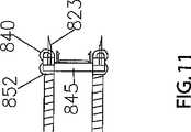
図9と図10に示したように、突き刺しランス623は、プランジャシール640に完全に取り囲まれてもよい。代替として、図11に示したように、突き刺しランス823が下流にプランジャシール840から突出する注射器を構成することもできる。必要に応じて、ガスセル用隔室696は、ガスセル625を取り囲んでいるが突き刺しランス623がガスセル625に容易に届くように設計された単体で個別に作成されてもよい。
【0111】
注射器620を組み立てる際、注射器筒643にキャップ690を取り付ける前に、針637の下流端を位置合わせ円盤646の中央穴624とガスセル625の内側開口627と針用エンドキャップ690内の針穴635に通すことにより、針637が針用エンドキャップ690内に取り付けられる。位置合わせ円盤646の中央穴624と針用エンドキャップ690の針穴635は、針637を滑りばめ状態で取り囲み支持するように寸法と形状が決定される。
【0112】
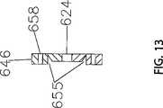
プランジャ648の下流方向移動行程の終点の直前に下流プランジャ端部652と針ヘッダ642をロック係合させるための針ヘッダロック656が提供される。図示したように、ヘッダロック656は、係合円盤645に取り付けられそこから下流に突出する直径方向に離間された1対のかえし付きランス659を有する。かえし付きランス659は、針ヘッダ642の周縁とロック係合するように形状と寸法が決定される。このロック係合は、位置合わせ円盤646内の円形凹状溝655によって容易にされ、円形凹状溝655は、ランスの先端が、下流方向に動くときに外方に曲がって針ヘッダ642の周縁を通過し、その後で内方に跳ね返って針ヘッダ642をロック係合状態で掴むことを可能にする。針ヘッダ642の径は、針ヘッダ642の周縁が、位置合わせ円盤646の円形凹状溝655を部分的に覆い、針ヘッダ642がヘッダロックランス659を保持しやすいように選択される。図示したものの代わりに他の適切なスナップ嵌め構成要素や又は他のロック係合構成要素を使用できるが、図示した構成がコンパクトで効果的である。注射器のこの実施形態の寸法は、針用ポートシール641と針ヘッダ642の間にいかなる実質的な隙間も生じないように選択されなければならない。薬剤が溜まる可能性のある隙間を残すのことは不利である、この目的は、注射器に吸い込まれ充填された実質的に全ての薬剤を注射することである。
【0113】
図12は、図9に示した本発明の実施形態による位置合わせ円盤646を平面図で示し、図13はその断面図である。位置合わせ円盤646は、中空針637が通ることができるように寸法と形状が決められた中央穴624を有するほぼ円形である。係合円盤645に取り付けられたかえし付きランス659を収容するように寸法と形状が決定された円形凹状溝655は、位置合わせ円盤646の中央穴624と同心である。
【0114】
図9に戻ると、内側「ドーナツ穴状」開口627を備えガス蓄積室680に適切な無毒圧縮ガスを収容している環状ガスセル625は、ガスセル隔室696内にぴったりと嵌るように寸法と形状が決定される。ガスセル625の材料は、突き刺しランス623がガスセル625に(好ましくは約6p.s.i.gの圧力で)押し付けられたときに、ガスセル625が突き刺しランス623によって破られるように選択される。
【0115】
針用エンドキャップ690の針穴635から圧縮ガスが漏れるのを防ぐために、針用エンドキャップ690の針穴635の上流方向端で、針用エンドキャップ690に固定された環状針膜668が針637を取り囲んでいる。膜668は、実質的に前述の膜68と似ており、針用ポート閉鎖要素として働く。注射器の使用後に針637が内腔674に格納された後で針膜668が針穴635を覆い、針637が針穴635を通って下流に突き抜けるのを防ぐ。
【0116】
本発明のこの実施形態では、注射器620は、更に、プランジャ突条部670及びこれと協働するロック嵌合突条部671を有し、これらの構造、位置及びロック動作は、プランジャ突条部470とロック係合突条部471に関して前に説明したものとほぼ似ている。
【0117】
図14、図15及び図16を参照すると、操作の際に、注射器620は、従来の注射器に薬剤が充填されるのと同じように薬剤が充填される。ユーザは、上流プランジャ端部650に下流方向の力を加え、それによりプランジャ648とプランジャシール640が、注射器筒643内を軸方向下流に動かされる。プランジャシール640の下流方向への動きによって、注射器筒643に閉じ込められたほとんどの空気が、針637の上流吸込口を通って針637の下流先端から押し出される。ほとんど全ての空気が注射器筒643から押し出され、プランジャ突条部670がロック嵌合縁671と係合する前に、針637の下流先端が、小瓶(図示せず)に入れられた薬剤に浸される。針637の先端を薬剤に浸したままで、プランジャ648に上流方向の力を加え、それにより薬剤が小瓶から注射器筒643の空洞674内に吸い込まれる。薬剤が空洞674に入った後で、針637の下流先端を上方に向けて注射器筒643内で残留空気が薬剤から浮き上がるように注射器620を保持し、その後で、プランジャ648に下流方向の力を加えて注射器筒643から残留空気を押し出す。図14を参照すると、注射器620に薬剤が充填されたとき、薬剤は、注射器筒643内に収容され、プランジャ648のプランジャシール640、係合円盤645、及び位置合わせ円盤646の間に閉じ込められる。
【0118】
図14に示したように、注射器620に薬剤を充填した後で、プランジャ648に下流方向の射出力を加え、プランジャ648を強制的に軸方向下流に押し、それにより薬剤が針ヘッダ642に押し込まれ、薬剤が針637から放出される。ユーザがプランジャ648に下流射出力を加えるとき、下流プランジャ端部652のプランジャシール640は、注射器筒643に収容された薬剤に下流方向の付勢圧力を与える。ユーザがプランジャ648に加えるこの下流方向の付勢圧力は、薬剤を針637の上流吸込口から患者に針637の下流先端を介して強制的に注入するのに十分である。薬剤は、注射中にプランジャ648によって圧力がかけられ、従ってこれに対応する上流方向の付勢圧力を係合円盤645に加えるが、係合円盤645上に生じる力は、係合円盤645をプランジャ648の内側面654に固定する摩擦力に打ち勝つのには十分ではない。
【0119】
図15を参照すると、このように実質的に全ての薬剤が空洞674から排出された後で、引き続き射出力を加えると、針用ポートシール641の下流端が針ヘッダ642に押し付けられ、それにより針ヘッダ642が密閉され、その結果、薬剤や他の流体がそれ以上針637の上流吸込口から患者に強制的に送られなくなる。針用ポートシール641が針ヘッダ642を係合封止したとき、かえし付きランス659が、位置合わせ円盤646の凹状溝655内に突出する。プランジャ648に下流方向の力を加えたとき、かえし付きランス659の薄い下流側が、針ヘッダ642の外縁よりも下流側に押動されて位置合わせ円盤646の凹状溝655に差し込まれる。かえし付きランス659のかえしは、針ヘッダ642と係合し、針ヘッダ642に固定される。何故なら、かえし付きランスの急勾配の上流側は針ヘッダ642の外縁を越えて上流側に押動できないためである。
【0120】
図16を参照すると、このように全ての薬剤が空洞674から排出された後で、ユーザが引き続きプランジャ648に下流方向の射出力(ここでは、注射後力(post-injectionforce))を加えると、突き刺しランス623が位置合わせ円盤646の貫通穴658を通り、突き刺しランス623がガスセル625に強制的に当てられる。突き刺しランス623がガスセル625に当てられると、突き刺しランス623がガスセル625を破り、それによりガスセル625から圧縮ガスが放出される。放出ガスは、穴658から漏れて、注射器筒633内でプランジャ648を上流方向に付勢して動かす。一方、注射器筒633から出るプランジャ648の動きは、プランジャ突条部670とロック嵌合突条部671との係合によって防止又は阻止される。放出ガスは、注射器筒643内で係合円盤645とプランジャ648の内側面654との間の摩擦力に打ち勝つのに十分な上流方向の付勢圧力を加え、それにより、係合円盤645が、プランジャ648の内腔639内で軸方向上流に摺動する。係合円盤645が内腔639内で上流に摺動するとき、針ヘッダ642がかえし付きランス659によって係合円盤645に固定されるので針637を内腔639内に支持し、それにより針637がプランジャ648の内腔639内に引っ込められる。(この実施形態では、針搬送体は、係合円盤645とヘッダロック656の組み合わせからなる。)当然ながら、蓄積室680内には、上流方向の付勢圧力が針637を必要な距離だけ上流に動かすのに十分な力を生成できる加圧ガスがなければならない。ガスセル625内の圧縮ガスの圧力は、ガスセル25に関して前に指定した範囲内であることが予想される。
【0121】
針格納段階の終わりに、針637の更なる上流への動きが、親指受け台651によって限定される。係合円盤645は、プランジャ648の上流プランジャ端部650近くでプランジャ648の内側面654と摩擦状態で係合し、これにより針ヘッダ642と針637がプランジャ648の内腔639内に保持される。
【0122】
針637の下流先端が針穴635を通るとき、針膜668のテーパ部分が平坦化して針穴635を覆い、これにより針637の再伸出が妨げられる。
【0123】
ガスセル625が破られ、ガス貯蔵室680から圧縮ガスが放出されたとき、圧縮ガスの放出によって生じる上流方向の付勢圧力は、プランジャ突条部670を注射器筒643のロック嵌合突条部671の上流方向に押動するには不十分である。プランジャ648が注射器筒643内にそのようにロックされ、針637がプランジャ648の内腔639に格納された後で、針637は、再使用できず身体的危害を引き起こすこともなく、適切に処分することができる。
【0124】
本発明の注射器の説明した全ての実施形態では、ガスが針、針ヘッダ及び他の注射器構成要素をプランジャ内腔内で上流に押すとき、内腔内に既にある空気が圧縮されることになる。この圧縮された空気は、プランジャ壁に、好ましくはプランジャロック突条部の上流に配置された小さな通気穴(図示せず)を設けることによって放出することができ、それにより針格納が容易になる。
【0125】
この明細書で説明し図示したものの変形は、当業者には容易に想起されよう。可能な改良、変更及び変形のいくつかの例は、以下の通りである。
【0126】
プランジャ48の内側面54、針用ポートシール41及びプラグプランジャ47によって画定された内腔39の容積はある程度減圧されてもよく、これが針組立体82の迅速な格納に役立ち、ガスセル25に閉じ込められたガス圧力の低減を可能する。
【0127】
ガスセル25は、突き刺しランス23で突き刺す代わりに、プランジャシール40で押しつぶされるか又は注射器筒43の内側円筒壁面33から引き剥がすことによって破られ、それによりプランジャ48の下流方向への動きによって破られることによって開かれてもよい。
【0128】
代替として、突き刺しランス23は、突き刺しランス23が穿孔器46からガスセル25の方に突出するように穿孔器46に取り付けられる代わりに、突き刺しランス23が係合リング45からガスセル25の方に下流に突出するように係合リング45の下流端に固定された(又は、あまり望ましくないが、下流端のすぐに下流に配置された)穿孔器に取り付けられてもよい。そのような代替の実施形態では、穿孔器46の基部22を注射器筒43の内側円筒壁面28に貼り合わせるか、接合するか又は他の方法で取り付けることによって、穿孔器46を所定の位置に固定することができる。穿孔器の周囲を注射器筒の内側にぴったりと嵌めるか又は接着することは、ガスや他の流体が、針を通らずに穿孔器46の下流に漏れるのを防ぐか又は実質的に妨げるのに有効なはずである。
【0129】
ガス放出セルは、注射前に圧縮されたガスを収容する代わりに、個別の反応物を収容する2個以上の副隔室のそれぞれに気体ではなく化学反応性液体や場合によっては固体を収容してもよい。副隔室は、破られることになる一枚以上の壁によって互いに分離されてもよい。分割壁が破られると、副隔室内の反応物が混じって反応して、セルが破られたときに放出される加圧ガスを生成する。この代替案は、このような変形したセル25は、注射器20が使用されるまで圧力がかからないという点で多少有利になる。
【0130】
針カバー44と穿孔器マウント69は、2個の別個の部品として製造され、切り離し可能な保持手段によって結合されてもよい。
【0131】
注射器を完全に組み立てた製品として製造し販売することが望ましいと考えられるが、注射器を半組立体のセットとして製造し販売することもできる。例えば、針と針用ヘッダが別々に提供されてもよい。実施形態によっては穿孔器と穿孔器マウントが筒から分離された状態で販売され、ガスセルも別個に保管され注射器の使用直前に組み込まれ、その後で注射器の組み立てを完成させてもよい。注射器を半組立体のセットとして製造し販売する欠点には、針等の破損しやすい構成要素の損傷の可能性、不注意による突き刺しの危険、ガスセルの早すぎる破裂の可能性、及び構成要素の位置ずれの可能性がある。利点は、注射器の販売用の包装をコンパクトにできること、ガスセルを個別に包装できることである。この場合、ガスセルは、注射器の使用前にガスセル壁又は「皮」にかかる応力を小さくするために、それ自体が加圧された外側容器内に包装される。
【0132】
2個の噛み合い嵌合要素を連結するための多くの機械的手段が知られている。本明細書で説明し図示したプランジャ突条部/ロック嵌合突条部の例の代わりに様々な手段を選択することができる。
【0133】
必要とする構成要素の支持と位置合わせを行うための多くの機械的手段が知られている。半径方向の位置合わせが必要な場合には、位置合わせされた構成要素の半径方向の断面は、例えば1つの平らな側面を有する非円形でよい。或いは、さねはぎで位置合わせれてもよい。例として本明細書で説明し図示した位置合わせ構造の代わりに様々な位置合わせ技術を選択することができ、同じことは支持にも当てはまる。
【0134】
何らかの機械的事象が起きた後で要素を使用不可にするための多くの機械的手段が知られている。このケースでは、目的は、注射器の使用後に針を使用不可能にし、針をプランジャ内腔に格納した後でその再伸出を防止又は阻止するためのいくつかの手段を提供することである。本明細書で説明した針の再伸出を阻止するための一手段は、針用ヘッダの下流に配置され針の細い部分が通る弾性の膜である。針格納の完了後に、この膜は、針が通った穴を少なくとも部分的に閉じる。しかし、格納後に内腔から針が出るのを塞ぐための他の手段は容易に想起することができる。
【0135】
構成要素を互いに固定する場合、設計者と製造業者にある程度の自由裁量が与えられる。多くのケースでは、締りばめ、スナップばめ、ねじ切り、又はねじ接続で十分であり、これらは、接着剤と注射器の内側が接触するのを回避し、特に接着剤と注射薬剤が接触するのを回避することが望まれるので、接着より好ましい。
【0136】
以上は単なる例示であり、皮下注射針型注射器の機械設計の熟練者であれば、他の可能な等価物及び代替物を容易に想起できるであろう。
【0137】
従って、本発明は、前述の特定の実施形態によって限定されず、本発明の範囲は、特許請求の範囲に定義した通りである。
【図面の簡単な説明】
【0138】
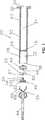
【図1】本発明により作成された注射器の好ましい実施形態による使い捨て空気圧格納式注射器の筒、ガスセル、ガスセル用の穿孔器、針カバー、及び係合リングを示す分解長手断面図である。
【図2】図1に示した注射器構成要素と共に使用するためのプランジャ、プランジャシール、針及び針用ヘッダを示す分解長手断面図である。
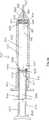
【図3】薬剤を注射器に吸い込むことができるようにプランジャが注射器筒から上流に拡張された状態の、完全に組み立てられた図1と図2の注射器を示す長手断面図である。
【図4】図3の注射器を示す長手断面図であり、注射器筒に吸い込まれた実質的に全ての薬剤が押し出され、プランジャが筒内にロックされ、そして針用ポートシールが針用ヘッダ内の針穴ポートと係合し封止した位置までプランジャが下流に押された状態である。
【図5】図4の注射器を示す長手断面図であり、針、針用ヘッダ及び針用ポートシールが、プランジャの格納内腔内に格納されて示されている。
【図6】本発明による使い捨て空気圧格納式注射器の代替の実施形態の長手断面図であり、ここで、係合リングは、針用ヘッダが係合リングの中央円筒開口内に位置決めされるように寸法と形状が決定され、筒から上流に部分的に突出しているプランジャを示す。
【図7】図6の注射器の筒の下流部分とそれと関連した内部構成要素を示す分解長手断面破断図である。
【図8】図6の注射器のプランジャとその関連した構成要素を示す部分分解長手断面破断図である。
【図9】本発明の更に他の実施形態による使い捨て空気圧格納式注射器とそれに使用する針の部分分解長手断面図である。
【図10】図9の注射器の下流プランジャ端部の長手断面詳細破断図である。
【図11】図9の注射器の下流プランジャ端部の代替の実施形態の長手断面詳細破断図である。
【図12】図9に示した注射器の位置合わせ円盤を示す半径方向平面の端面図である。
【図13】図12の位置合わせ円盤を示す長手断面図である。
【図14】図9の注射器を示す長手断面図であり、プランジャが注射器筒から上流に部分的に拡張した状態である。
【図15】図9の注射器を示す長手断面図であり、プランジャが注射器の筒内に完全に押し込まれロックされた状態である。
【図16】図15の注射器を示す長手断面図であり、針、針用ヘッダ及び針用ポートシールがプランジャの格納内腔内に格納されているように示され、プランジャが注射器筒内にロックされている。【Technical field】
[0001]
The present invention generally relates to a pneumatic safety syringe of the type used with hypodermic needles. In the syringe according to the present invention, after use of the syringe, the plunger is locked into the syringe body (cylinder) and the needle is stored in the storage lumen of the plunger, thereby causing inadvertent piercing after use and undesirable movement of the plunger from the cylinder. Reextension is prevented. Needle storage is accomplished by the release of pressurized gas or other suitable pneumatic means, for example, by rupturing the gas cell or causing a chemical reaction to release the gas. This common type of syringe is sometimes referred to as a “retractable syringe”. The term means that the needle is stored within the body of the syringe.
[Background]
[0002]
It is well known that many dangerous infectious diseases spread through contact with the body fluids of infected people. After use of the syringe, residual body fluid is likely to remain on or in the syringe needle. As such, syringes are generally designed to be disposable. To handle safely after use, the needle of the syringe must be covered, for example to prevent the needle from accidentally sticking into a person who is collecting the syringe for disposal and injecting residual fluid into the person . In general, a syringe is provided with a protective cap that can be used to cover the tip of the needle after use. However, it is sometimes happening that a person trying to cap a used needle loses the cap and pierces himself by mistake, resulting in an infectious disease. In addition, epidemics and dangerous illnesses are prevalent by drug addicts who share and reuse needles and syringes designed for single use.
[0003]
There have been several attempts to address this problem by incorporating into the syringe a mechanism for retracting the needle within the syringe after use. U.S. Pat. No. 5,334,155 (Sobel, Aug. 2, 1994) discloses a needle guard having a vacuumed double wall protective sheath. Before use, the sheath is folded inward by evacuating the protective sheath to some extent, so that the needle protrudes from the protective sheath and can be used for injection. After injection, one part of the double wall of the protective sheath can be broken to bring the inside of the protective sheath to atmospheric pressure. The protective sheath then expands to cover the protruding needle. However, this protective sheath may obscure the field of view where the needle is inserted into the patient, making it difficult to use the syringe. Furthermore, the user is inconvenient because after injection, the user's hand position on the syringe must be changed to break the double wall and activate the sheath. As such, the safety mechanism does not automatically operate after drug injection.
[0004]
The protective safety device shown in US Pat. No. 5,188,614 (Hart, Feb. 23, 1993) is a hollow cylindrical casing that encloses a syringe. A two-component foaming agent is disposed at the downstream end of the casing. After injection, the two components of the two-component foaming agent are mixed, creating an expanded foam mixture that forces the syringe back into the casing and surrounds the needle. However, this device is designed so that the casing tightly covers the conventional syringe, and the size and feel of the device is different from the conventional syringe, so that the casing does not interfere with the use of the syringe when making an injection. It has the disadvantage of becoming. In addition, a significant amount of material is required to make the protective sheath, which increases the cost of both manufacturing and disposal of the device.
[0005]
US Pat. No. 6,193,695 (Rippstein, Feb. 27, 2001) discloses a safety syringe with a vacuum chamber upstream of the plunger head. After injection of the drug, the plunger head engages with the needle head, the ambient atmospheric pressure outside the needle head acts on the needle head, and the needle and plunger are forced into the syringe body against vacuum. The user can then snap the plunger arm to make the needle unusable. This device has the disadvantage that the needle may accidentally re-extend if the user does not break the plunger arm. Yet another disadvantage of this device is that if the user does not apply a constant injection force, the plunger retracts under vacuum before the drug is completely injected, thereby causing the syringe to operate in the reverse direction. There is a possibility.
[0006]
U.S. Patent No. 6,413,236 (Van Dyke, July 2, 2002) discloses a safety syringe with a vacuum chamber upstream of the plunger head. After injection of the drug, the plunger head engages with the needle head, the ambient atmospheric pressure outside the needle head acts on the needle head, and the needle and plunger are forced into the syringe body against vacuum. In this patent, in contrast to US Pat. No. 6,193,695, the needle is housed diagonally within the syringe body, whereby the pierced end of the needle is pressed against the inner surface of the syringe and the plunger arm is the syringe. Re-extension of the needle is prevented even when fully extended out of the body. However, this device has the disadvantage that if the user does not apply a constant firing power, the plunger will retract under vacuum before the drug is completely injected, which may cause the syringe to operate in the opposite direction. It has not been solved.
[0007]
The device disclosed in US Pat. No. 5,868,713 (Klippenstein, 9 February 1999) embodies significant improvements over previous syringe technology. This early Klippenstein syringe has a gas reservoir containing non-toxic compressed gas. This gas reservoir is broken by the needle header when the needle header is forcibly pushed in the downstream direction, and the released non-toxic compressed gas urges the needle header and plunger to slide upstream, An upstream biasing pressure is provided to retract the needle within the syringe body. After the needle is retracted, a locking mechanism prevents the plunger from moving in the downstream direction. However, at the end of the retracting phase, the plunger continues to expand toward the outside of the syringe barrel, so the user must reposition the hand by releasing the thumb from the thumb button at the end of the plunger. There wasn't. Furthermore, since the plunger is held in the locked extended position after storage, the expanded syringe takes up more space in the waste container than the conventional syringe. The object of the present invention is to overcome these and other disadvantages associated with this conventional Klippenstein design.
[0008]
A syringe designed to provide an optimal solution to the problem of preventing inadvertent needle sticks after using the syringe for injection will have the following characteristics:
1. The syringe mechanism is relatively simple, i.e. it must be made with as few moving parts as possible to fit its design purpose, and preferably has the same look and feel as a conventional syringe and is simple Must be able to operate.
2. The syringe mechanism must ensure that the needle is retracted after use or that the needle is otherwise covered to prevent inadvertent piercing.
3. Syringes must be relatively inexpensive to manufacture.
4). There should be minimal waste plastic and other materials discarded after use of the syringe.
5. Safety-related means should not significantly change the feel of the syringe in the user's hand.
6). After the needle has been retracted or shielded, it must be prevented from being exposed again by a reliable safety device.
Note that the simplicity of structure and operation (Aim 1 above) contributes to the achievement of the other five objectives.
[Prior art documents]
[Patent Literature]
[0009]
[Patent Document 1]
US Patent No. 5118614
[Patent Document 2]
U.S. Pat.No. 5,120,310
[Patent Document 3]
U.S. Pat.No. 5,122,118
[Patent Document 4]
U.S. Pat.No. 5,176,640
[Patent Document 5]
U.S. Pat.No. 5,188,614
[Patent Document 6]
U.S. Pat.No. 5,211,628
[Patent Document 7]
U.S. Pat.No. 5,224,936
[Patent Document 8]
U.S. Pat.No. 5,334,155
[Patent Document 9]
U.S. Pat.
[Patent Document 10]
U.S. Pat.No. 5,407,436
[Patent Document 11]
US Patent No. 5423758
[Patent Document 12]
US Pat. No. 5,433,712
[Patent Document 13]
US Pat. No. 5,533,970
[Patent Document 14]
U.S. Pat.No. 5,575,777
[Patent Document 15]
U.S. Patent No. 5578011
[Patent Document 16]
US Pat. No. 5,563,733
[Patent Document 17]
US Patent No. 5702367
[Patent Document 18]
U.S. Pat.
[Patent Document 19]
U.S. Pat.
[Patent Document 20]
U.S. Pat. No. 5,989,220
[Patent Document 21]
US Patent No. 6015438
[Patent Document 22]
U.S. Patent No. 6083199
[Patent Document 23]
U.S. Pat.No. 6086568
[Patent Document 24]
U.S. Pat.No.6090077
[Patent Document 25]
US Patent No. 6099500
[Patent Document 26]
U.S. Patent No. 6179812
[Patent Document 27]
US Pat. No. 6,183,440
[Patent Document 28]
US Patent No. 6193695
[Patent Document 29]
US Pat. No. 6,206,853
[Patent Document 30]
U.S. Patent No. 6210371
[Patent Document 31]
U.S. Patent No. 6221055
[Patent Document 32]
U.S. Pat.No. 6241707
[Patent Document 33]
US Pat. No. 6,267,749
[Patent Document 34]
US Pat. No. 6,615,525
[Patent Document 35]
US Pat. No. 6,409,701
[Patent Document 36]
U.S. Patent No. 6413236
[Patent Document 37]
U.S. Patent No. 6413237
[Patent Document 38]
U.S. Patent No. 6432087
[Patent Document 39]
US Pat. No. 6,458,105
[Patent Document 40]
US Pat. No. 6,447,472
[Patent Document 41]
U.S. Pat.
[Patent Document 42]
US Pat. No. 6,558,357
[Patent Document 43]
US Pat. No. 6,572,565
[Patent Document 44]
US Pat. No. 6,572,854
[Patent Document 45]
US Pat. No. 6,585,690
[Patent Document 46]
US Pat. No. 6,599,268
[Patent Document 47]
US Pat. No. 6,667,863
[Patent Document 48]
US Pat. No. 6,692,470
[Patent Document 49]
US Pat. No. 6740062
[Patent Document 50]
US Pat. No. 6,767,335
[Patent Document 51]
US6846301 specification
[Patent Document 52]
US Patent No. 6886713
[Patent Document 53]
US Patent No. 6872193
[Patent Document 54]
US Patent No. 7090656
[Patent Document 55]
U.S. Patent No. 7182734
[Patent Document 56]
US Pat. No. 7,258,678
[Patent Document 57]
US Patent 7294118
[Patent Document 58]
US Patent No. 7345517
[Patent Document 59]
US Pat. No. 7,512,224
[Patent Document 60]
US Patent Application Publication No. 2003/0040717
[Patent Document 61]
US Patent Application Publication No. 2003/0078540
[Patent Document 62]
US Patent Application Publication No. 2003/0176843
[Patent Document 63]
US Patent Application Publication No. 2004/0153034
[Patent Document 64]
US Patent Application Publication No. 2005/0159705
[Patent Document 65]
US Patent Application Publication No. 2005/0159707
[Patent Document 66]
US Patent Application Publication No. 2005/0215951
[Patent Document 67]
European Patent Application No. 0479217
[Patent Document 68]
Dutch Patent Application Publication No.9000292
[Patent Document 69]
International Publication No. 91/04760
[Patent Document 70]
International Publication No.99 / 25401
[Patent Document 71]
International Publication No. 2001/080930
[Patent Document 72]
International Publication No. 2004/082747
[Patent Document 73]
International Publication No. 2005/011792
[Patent Document 74]
International Publication No. 2005/070292
[Patent Document 75]
International Publication No. 2005/072801
[Patent Document 76]
International Publication No. 2006/017889
[Patent Document 77]
International Publication No. 2006/108243
[Patent Document 78]
International Publication No. 2006/119570
[Non-patent literature]
[0010]
[Non-Patent Document 1]
Maxxon Applauds New Federal Needlestick Act Press Release, Nov. 2, 2000, Business Wire
[Non-Patent Document 2]
Maxxon Safety Syringe Press Release, Feb. 2000, online: <http://www.micro-stocks.com/Research/MXON.htm>
[Non-Patent Document 3]
Maxxon Announces Safety Syringe Patent Filing, ADVANCE For Respiratory Care Practitioners, Daily News Watch, Feb. 2000, online: <http://www.advanceforrcp.com/previousdnw/rcdnwjan31.html>
DISCLOSURE OF THE INVENTION
[Means for Solving the Problems]
[0011]
The main object of the present invention is of the type for use with hypodermic needles where the needle is automatically retracted into the plunger's storage lumen and the plunger is locked within the syringe body (cylinder) after the drug injection is complete. It is to provide a syringe. Yet another object is to eliminate or mitigate the disadvantages associated with prior art syringe designs including the prior art Klippenstein syringe disclosed in US Pat. No. 5,868,713.
[0012]
The safety syringe according to the present invention comprises a syringe barrel, a plunger, and means for assembling a needle within the syringe. (The needle is part of the complete assembly or will be attached later, depending on the design chosen.) The overall structural features and operating characteristics of the syringe according to the present invention are other than those described herein. It is almost similar to that of the prior art design. Examples of the main features of the syringe of the present invention that differ from prior art syringes are as follows.
a. A plunger that is axially movable within the barrel includes an axially extending containment lumen with an open distal end for receiving the needle after use of the syringe. The lumen is sized to receive the combined length of the needle and a needle carrier described below so that the needle tip remains in the plunger lumen after storage.
b. A gas release cell is positioned distal to the plunger in the assembled syringe. The gas release cell (which in the preferred embodiment illustrated contains pressurized gas and may be referred to herein as a gas cell) is completely complete until the injection of the drug by the downstream movement of the plunger is substantially complete. It remains in a non-functional state. When used in the preferred embodiment detailed below, the gas cell is a separate and independent component that is individually incorporated into the syringe and contains a suitably selected non-toxic, non-corrosive pressurized gas. Is preferred. The gas cell is preferably burstable to release gas, but instead is a chemical reaction that is initially separated and controllably mixed to release pressurized gas after substantial completion of the injection. It may contain chemical components that cause
c. Of the plunger in the assembled syringeDistally The disposed gas release trigger means is operable to cause the gas release cell to release gas into the syringe in response to the downstream movement of the plunger as the plunger approaches the downstream movement end. In the preferred embodiment shown herein, for use with a separate rupturable gas cell, the gas discharge trigger means preferably has a perforator with a piercing lance, but instead the wall of the gas cell. Tearing or crushing means may be provided. When using alternative gas release cells, such as two compartment cells, each containing a separate chemical component that undergoes a chemical reaction and releases a pressurized gas when mixed, the gas release trigger can be, for example, substantially injection Means can be provided for breaking the septum between the two compartments after completion and then breaking the outer wall of the gas release cell at the same time or preferably a little later.
d. A needle carrier is coupled to the needle near the proximal end of the needle. This needle carrier is movable axially within the plunger lumen and has a distal receiving surface on which pressurized gas acts.The needle carrier is frictionally engaged with the inner wall of the plunger lumen. Also The needle carrier moves into the plunger lumen under gas pressure to carry the needle and store the needle in the lumen. (Of course, there must be an appropriate flow path through which the gas can reach the needle carrier. In some cases, it is desirable to throttle the flow path to prevent the pressurized gas from acting abruptly on the receiving surface of the needle carrier. The needle may be formed with a needle header at its proximal end, or may be otherwise secured to a needle header located at or near the proximal end of the needle. Such a needle carrier of the latter example may be fixed to or coupled to the needle header. The needle carrier preferably comprises a sealing element slidably engaged with the lumen wall. In a preferred embodiment, the lumen is squeezed at the distal end, so that the sealing element of such an embodiment can be used for large lumens after moving upstream from the squeezed distal portion of the lumen. The diameter must be able to expand elastically so that it is in close contact with the wall of the diameter section.
e. In addition to a needle carrier designed to provide an acceptable level of gas sealing upstream of the pressurized gas, yet another to prevent or delay unnecessary leakage of gas from the syringe before the needle is fully retracted. One or more gas barriers are provided. At least some of the gas barriers can be achieved by a suitable slip fit or interference fit between the mating components. In some cases, the slidable engagement of the parts is sufficiently tight to prevent significant gas loss. Some of these barriers also serve to prevent unwanted leakage of medication from the syringe. The objectives are, of course, (i) injecting substantially all of the drug in the syringe into the patient and eliminating leakage from the syringe, and (ii) pushing the needle carrier into the plunger lumen with gas pressure after injection. The needle is fully retracted and the pressurized gas is not allowed to dissipate until the needle retracting phase of the syringe operation is complete.
f. Preferably, a needle reappearance barrier is provided to prevent or prevent the needle from moving downstream after the needle is retracted into the lumen.
[0013]
Of course, by incorporating the inventive features of the present invention into the syringe, the main function of the syringe (i.e., inhaling the drug into the barrel and injecting the drug into the patient) should not be significantly hindered. For this reason, for example, when filling a syringe barrel with a medicine and injecting the medicine into a patient, the upstream movement of the needle and the needle carrier into the lumen must be prevented. Depending on the specific syringe design chosen, the aforementioned objectives can be achieved almost completely by friction on the plunger and hand pressure.
[0014]
The design of the gas flow path, gas pressure sensitive components and surfaces, and gas and liquid shut-off elements in any embodiment of the syringe design according to the present invention has little potential for drug loss or leakage and the normal syringe design. It should be effective to allow operation of the normal drug filling phase and normal drug injection phase with little hindrance to appearance and feel. The aforementioned objectives are common to many types of syringe designs, and any skilled syringe designer should be able to easily address this description. It should be noted that the syringe according to the present invention must be designed so that the gas pressure is effective during the needle retracting phase of the operation which pushes the needle into the plunger lumen but does not push the plunger upstream from the cylinder. For this reason, the needle must be attached or coupled to a movable element that moves in response to gas pressure, and both the movable element and the needle can freely enter the plunger lumen and move upstream under gas pressure. There must be. When the movable element is pushed upstream, the needle necessarily moves with the movable element. In addition, the syringe must be designed so that the gas released from the gas release cell can reach the movable element and apply an effective upstream force to the movable element. When retracting the needle, the upstream movement of the plunger should be hindered by the interaction or engagement of the syringe components as well as the pressure of the user's hand. Leakage of gas downstream from the syringe through the needle hole is wasteful and inefficient and must be prevented or obstructed while the needle is retracted. After the needle is retracted, it must be prevented from reappearing from the plunger lumen.
[0015]
In order to realize some of the main advantages of the preferred embodiment of the present invention, the syringe according to the present invention also includes a plunger for preventing or preventing the plunger from unnecessarily re-extending from the barrel after use of the syringe. Provide a lock. The plunger lock has a plunger engaging element fixed to the plunger and an engaging element fixed to the cylinder and engaged with the plunger engaging element. These engaging elements are arranged in engaging contact with each other near the downstream moving end of the plunger. As the plunger moves further downstream than the engagement contact position, the plunger is locked into the syringe at or near the downstream moving end of the plunger. In order to prevent the plunger from being pushed unnecessarily by the gas before the lock and moving upstream, the plunger lock is located at a position where the gas discharge trigger means is operated in the plunger downstream movement path to release the gas to the gas discharge cell. It may be configured to lock the plunger to the cylinder at an upstream position. However, the operation of pushing the plunger to its downstream end is usually done with a continuous hand movement, so that the plunger lock occurs before or substantially simultaneously with the rupture, or the rupture occurs more than the plunger lock. Regardless of what happens some time ago, the amount of plunger movement is usually sufficient to lock the plunger in the barrel and break the gas release cell.
[0016]
The syringe according to the present invention is placed downstream of the needle tip after the needle is retracted into the plunger to prevent or prevent the needle from moving downstream after the needle is retracted into the lumen. A needle reappearance barrier may be provided. This barrier may preferably be a suitable needle port sealing means.
[0017]
In some preferred embodiments of the syringe of the present invention, the barrel is divided into a small downstream chamber for containing the gas release cell and the gas release trigger means and an upstream chamber for containing the medicine to be injected. And the chambers are separated by a radial chamber dividing wall having an axial bore for discharging the drug from the upstream chamber into the needle and receiving the needle in the plunger lumen after injection.
[0018]
The syringe of the present invention in the above-described embodiment may further include an engagement ring in the downstream chamber that is slidable and frictionally engaged with the inner peripheral wall of the downstream chamber and is movable in the axial direction. . The engagement ring must be relatively stationary in the downstream chamber unless it is deliberately applied. The engagement ring is disposed between the gas release cell and the radially dividing wall and has a central opening. The drug flows from the upstream chamber into the needle through this central opening, and after injection, the needle passes through this central opening and enters the plunger lumen. The engagement ringGas release trigger means A buffer element is provided for confining the gas cell to facilitate rupture of the gas cell. The engagement ring engages with the needle header to support the needle header and facilitates alignment of the needle with the needle header in the downstream chamber. The distal end of the plunger engages with the upstream end of the engagement ring near the downstream moving end of the plunger, and when the plunger has finished moving in the downstream direction,Gas release trigger means It is preferable to make it rupture by being pressed against.
[0019]
First exemplary embodiment
In one embodiment of the present invention, a disposable pneumatic needle storage safety syringe is operably or partially disposed within the syringe barrel and the barrel to reduce the risk of inadvertent needle stick after use. The following components are also included: a hollow plunger with a hollow interior defining a containment lumen, a needle port seal, a needle header for holding a needle, a slidable with an axial opening in the center. A movable cylindrical object (hereinafter sometimes referred to as an “engagement ring” for reasons described below), a gas cell, a perforator, and a plunger lock. The syringe cylinder is hollow and includes an upstream cylinder opening and a downstream cylinder opening opposite to the upstream cylinder opening in the axial direction. The plunger is sized and shaped to fit within the syringe barrel and is mounted for axial movement within the syringe barrel. The plunger has a plug opening for receiving the plug, an upstream plunger end protruding from the upstream opening of the syringe barrel, and a downstream plunger end. The diameter of the downstream plunger end is smaller than the diameter of most part of the length of the plunger cylinder. The inner diameter of the plunger end is selected such that the needle port seal slides into the downstream plunger end during the injection phase.
[0020]
During the post-injection retraction phase, the needle port seal is moved upstream in the plunger retraction lumen by the release of pressurized gas from the gas cell at the end of the plunger downstream travel stroke, as described in more detail below. Is pushed. The needle port seal frictionally engages the inner surface of the downstream end of the plunger, thereby preventing the drug from leaking through the needle port seal and into the storage lumen when administering the drug. The storage lumen within the plunger is defined by the needle port seal, the upstream plunger end, and the inner surface of the plunger. The plug opening provides an opening that allows the insertion of a tool to reach the internal parts of the syringe during assembly to facilitate assembly of the syringe components. After assembly of the syringe, the plunger plug is snapped into the plug opening, thereby sealing the plunger storage lumen. A slidable plunger seal surrounds and is attached to the downstream plunger end. The dimensions and materials of the plunger seal are such that the plunger seal slidably contacts the inner surface of the syringe barrel, (i) prevents the drug from leaking through the plunger seal, and (ii) the plunger is longitudinal. Selected to be movable.
[0021]
A movable engagement ring is slidable but frictionally engaged with the inner surface of the syringe barrel and is located downstream of the plunger seal. The engagement ring is sized and shaped to mate with the interior of the syringe barrel and is positioned for limited axial displacement within the syringe barrel. For this reason, the inside of the syringe barrel is axially directed to the longer upstream chamber and the shorter downstream chamber separated by a chamber dividing wall with a central opening large enough to allow the narrow downstream end of the plunger to pass sufficiently. It is divided into. From upstream to downstream in the downstream chamber, (i) an engagement ring surrounding the punch neck and the needle header body in an engaged state within the central opening; (ii) a gas cell; and (iii) a punch body and tip A piercing lance facing the gas cell is arranged.
[0022]
The engagement ring is not moved from the initial rest position adjacent to the chamber divider wall until the injection phase is complete, and after the injection phase, the plunger is moved axially downstream by the pressure of the user's hand applied to the plunger. As a result, the downstream end of the plunger hits the engagement ring, and the engagement ring is forcibly pushed axially downstream. Movement of this engagement ring after injection causes the gas cell to move downstream, thereby forcing adjacent perforators and gas cells into contact with each other and eventually breaching the gas cell by the perforator, resulting in this explanation. , The compressed gas stored in the gas cell is released and the needle is forcibly stored in the storage lumen.
[0023]
The hollow needle header is attached to the central opening of the engagement ring. The diameter of the needle header is such that, during assembly, a compression seal is created between the needle header and the engagement ring by pushing the needle header into the inner opening of the engagement ring, thereby Selected to prevent drug from leaking downstream of the engagement ring. A hollow needle is joined or otherwise attached to the downstream end of the needle header. When the syringe is filled with drug, the drug is trapped in the syringe barrel downstream of the plunger seal and needle port seal and upstream of the engagement ring and needle header. In one embodiment of the present invention, the needle header is disposed within the engagement ring such that the upstream portion of the needle header projects upstream from the central opening of the engagement ring.
[0024]
The engagement ring achieves several purposes as follows.
(A) providing a compression seal that engages the peripheral cylindrical wall of the syringe barrel to provide stability and prevent unwanted unwanted fluid flow;
(B) Engage the central axial opening with the needle header to hold the needle header and needle in place while injecting the drug into the patient.
(C) Engaging the central axial opening with the perforator neck and engaging the neck with the needle header prevents premature perforation of the gas cell by the perforator.
(D) The above engagement facilitates the radial alignment of the gas cell and the perforator and facilitates the positioning of the gas cell with respect to the piercing lance, so that the gas cell at the end of the plunger travel in the downstream direction is facilitated. Facilitates optimal drilling.
(E) Facilitating accurate alignment between the needle port seal and the needle header, thereby facilitating accurate connection between the needle port seal and the needle header to facilitate accurate storage of the needle.
(F) The engagement of the gas cell at the end of the downstream travel of the plunger and the displacement of the gas cell causes the gas cell to move downstream to the perforator to contact and rupture, releasing the compressed gas, thereby releasing the needle assembly. Is stored in the storage lumen of the plunger.
[0025]
In this embodiment, an annular gas cell containing compressed gas is mounted downstream of the engagement ring in the syringe barrel. The gas cell is sized and shaped to fit snugly within the syringe barrel. A perforator is attached downstream of the gas cell. The perforator may be joined or otherwise attached to the inner surface of the syringe barrel downstream of the engagement ring, or joined or otherwise attached to the downstream barrel opening of the syringe. It may be joined to or otherwise attached to the needle hole mount. The perforator has one or more piercing lances, a neck, and an inner opening. The piercing lance is attached to the punch so that the piercing lance protrudes upstream from the punch toward the gas cell. The neck of the perforator is mounted such that the neck protrudes from the perforator through the annular hole in the gas cell to the inner opening of the engagement ring, thereby contacting the needle header. The neck of the perforator allows precise alignment of the needle header, gas cell and piercing lance and prevents the needle header and needle from moving in the downstream direction. The orientation of the perforator may be reversed if necessary so that the piercing lance projects downstream toward the gas cell located downstream.
[0026]
The perforator mount comprises a needle hole and a needle membrane, which serves as a needle port closure. The needle is mounted so as to protrude from the needle membrane through the inner opening of the perforator and to protrude downstream from the needle hole. The needle membrane is preferably fixed about and around the needle hole of the needle hole mount and is tapered at about 30 degrees relative to the axis where the needle membrane contacts the needle. After the needle is retracted, the needle membrane covers the needle hole and prevents the needle from re-extending from the needle hole. The needle hole mount is joined to or otherwise attached to the needle cover. This needle cover provides a protective sheath for the needle prior to use and can be twisted, snapped off or otherwise removed from the needle hole mount prior to use of the syringe so that the needle can be used Be exposed as you can. The needle cover, punch mount, and punch may be manufactured as separate parts or as a single part. In the case of a single part, it must be possible to twist or detach the needle cover from the punch mount before use without damaging the punch.
[0027]
In operation, after the syringe is filled with the medicine, when the user applies a radiant power to the plunger, the plunger seal at the downstream end of the plunger is contained between the plunger seal in the syringe barrel and the engagement ring. Apply a biasing pressure in the downstream direction. This downstream bias pressure applied to the plunger by the user is sufficient to inject the drug from the needle's upstream suction port into the patient through the needle's downstream tip. The releasable frictional force that secures the engagement ring to the inner surface of the syringe barrel counters the downstream biasing pressure applied to the engagement ring by the drug as it passes through the needle upstream inlet.
[0028]
When substantially all of the medication has been injected into the patient, moving the plunger further downstream causes a needle port seal located at the end of the downstream plunger to seal the needle header so that the needle No further drugs or other fluids can be delivered to the patient from the upstream inlet. A downstream force (post-injection force) applied by the user to the plunger overcomes the releasable frictional force that secures the engagement ring to the inner surface of the syringe, thereby causing the engagement ring to be injected into the syringe barrel by hand pressure. The inside can be slid axially downstream. However, the downstream movement of the needle header is limited by the neck of the perforator in contact with the needle header. When the needle header contacts the neck of the punch that projects upstream of the punch, further downstream movement of the needle header is prevented. By continuing to apply post-injection force to the plunger, the engagement ring slides axially downstream and contacts the gas cell. Thereafter, the gas cell moves downstream and eventually the gas cell hits the piercing lance of the perforator. The piercing lance breaks the gas cell so that non-toxic compressed gas is released from the gas cell into the area surrounded by the syringe barrel perforator, engagement ring and needle port seal.
[0029]
The released compressed gas is trapped in the syringe barrel. The purpose is to provide an upstream biasing pressure in the syringe barrel upstream of the gas cell sufficient to overcome the frictional force between the needle port seal and the downstream plunger end. The biasing pressure in the upstream direction causes the needle port seal to slide upstream and enter the storage lumen of the plunger. Thus, while the needle port seal is moving upstream, the needle port seal remains attached to the needle header that is joined or otherwise fixed to the needle so that the needle is retracted. Stored in the lumen. The released gas remains under pressure and generates an upstream biasing pressure that acts on the needle port seal correspondingly, energizing the needle port seal, needle header and needle to retract the plunger. Slide upstream within the lumen, thereby retracting the needle within the storage lumen.
[0030]
Corresponding upstream movement of the plunger is prevented or prevented by a plunger lock that engages and locks the plunger within the syringe barrel when the plunger reaches its downstream end. In a preferred embodiment, the circumferential plunger ridge is configured to have a thin downstream side and a steep upstream side. As a result, when a downstream force is applied to the plunger, the thin downstream side of the plunger lock slides downstream of the upstream barrel opening of the syringe barrel. The upstream cylinder opening has a diameter slightly smaller than the outer diameter of the plunger. When the gas cell is breached and the compressed gas is released, the upstream energizing pressure generated by the discharge of the compressed gas forces the steep upstream side of the plunger ridge to the upstream beyond the upstream cylinder opening of the syringe cylinder. Insufficient to move. Since the downstream side of the edge is thin, the plunger can pass through the upstream cylinder opening relatively easily and slide in the downstream direction.
[0031]
There must be pressurized gas in the gas cell that can generate sufficient force for the upstream biasing pressure to move the needle port seal upstream by the required distance. In a syringe designed for evaluation as a pre-production prototype, the standard value of gas pressure in the gas cell is expected to be in the range of about 5 to about 20 p.sig, and this pressure should not exceed about 9 p.sig. Is preferred. Note that the speed and reliability of needle storage is highly dependent on the gas pressure selected. Therefore, an empirical approach must be taken. The gas pressure should be sufficient to store the needle relatively quickly, but the gas release at the time of rupture will cause more user and syringe components to be impacted more than necessary, or the storage of the needle will cause fluid to splatter There must not be. These objectives are easily achievable with a syringe constructed in accordance with the present invention, especially in contrast to conventional designs where needle storage has been achieved by spring action.
[0032]
Most components of the syringe are preferably made of a plastic material. The needle port seal, the engagement ring and the plunger seal are preferably manufactured from rubber or the like. This is because these parts function more properly when made of a softer material than the syringe barrel. All rubber parts in the syringe are coated with a medical lubricant as commonly used in the industry. In general, the needle is made of stainless steel or a special hard and strong plastic material.
[0033]
The above syringe embodiments of the present invention can be adapted to many volume sized syringes including, but not limited to, 1, 1.5, 2, 3, 5, 10, 20 mL syringes.
[0034]
Second exemplary embodiment
In the second embodiment of the present invention, the syringe has some major changes over the first exemplary embodiment of the present invention described above. Specifically, the engagement ring includes a central cylindrical opening in the engagement ring that includes a needle header that includes an upstream end of the needle header such that the upstream end of the needle header is flush with the upstream end of the engagement ring. It has been modified and extended so that it can be placed inside. Furthermore, the needle port seal is first attached to the downstream end of the plunger such that the downstream end of the needle port seal is flush with the downstream end of the downstream end of the plunger. Compared with the first embodiment, these changes can more appropriately align the needle port seal and the needle header at the post-injection stage of the syringe operation. As a result, the needle port seal and the needle header The coupling mechanism between them becomes more precise than in the first embodiment.
[0035]
In this second embodiment, the plunger lock functions in much the same way as the plunger lock of the first embodiment, but instead of using the upstream barrel opening of the syringe barrel as a locking element, A circumferential ridge is provided which is similar in design to the ridge on the outer cylindrical surface of the plunger but is inclined in the opposite direction. The two ridges are positioned to engage each other just before the plunger reaches its downstream end. The engagement between the shoulders of the two ridges in their locked position is safe against almost any large destructive force applied to the syringe.
[0036]
Third exemplary embodiment
In a third syringe embodiment of the present invention, the perforator is attached to the downstream plunger end rather than having a piercing lance located downstream of the gas cell and projecting upstream from the perforator toward the gas cell. And a piercing lance protruding in the downstream direction from the downstream plunger end toward the gas cell.
[0037]
An engagement disk is disposed in the downstream end of the plunger to prevent the drug from entering the plunger's storage lumen while injecting the drug into the patient. A needle port seal is fixed to the downstream end of the engagement disk. Furthermore, a header lock is fixed to the engagement disk and protrudes downstream from the engagement ring. In the illustrated embodiment, the header lock has a protruding barbed lance with barbs that grip the needle header. When the engaging disc fits within the plunger, the engaging disc carries the disc-shaped needle header together and consequently carries the needle.
[0038]
The hollow needle end cap is sized and shaped to mate with the downstream end of the syringe barrel. The needle end cap has a needle hole which is aligned with the upstream cylinder opening of the syringe cylinder in the axial direction and is opposed thereto.
[0039]
The alignment disk has an upstream end of the needle end cap within the needle end cap so that a gas cell chamber is formed between the base of the needle end cap and the downstream end of the needle end cap. It is securely attached in the vicinity. The alignment disk has a central needle hole concentric with the central hole of the alignment disk and a circular concave groove. The concave groove is sized and shaped to accommodate the header lock lance when the header lock lance moves downstream to grip the needle header. The needle end cap includes one or more through holes that are sized and shaped to allow a piercing lance attached to the downstream plunger end to pass therethrough.
[0040]
It is preferable that the needle membrane is fixed around the needle hole of the needle end cap. The needle membrane acts as a needle port closing element.
[0041]
Advantages of the present invention
An advantage of the present invention is that when the needle is retracted into the plunger lumen, the needle and all components attached to the needle are completely disconnected from the distal end of the syringe barrel and the distal end of the syringe plunger, so that the plunger lumen To be held in place.
[0042]
An advantage of the present invention is that the operation of the safety mechanism is relatively simple in that the inhalation of the drug into the syringe and the injection of the drug into the patient are substantially conventional. To initiate the needle retracting phase of the syringe operation, the user need only move the plunger by a shorter displacement, continuing to apply a downstream force to the plunger after the drug has been substantially expelled from the syringe. The overall structure of a syringe containing a needle storage element requires little change in the appearance and feel of the syringe according to the present invention compared to the appearance and feel of a conventional syringe. This feature is in common with the earlier Klippenstein syringe briefly described above, as opposed to the safety mechanism incorporated in the design disclosed in US Pat. Nos. 5,334,155 and 5,188,614. It is.
[0043]
Yet another advantage of the preferred embodiment of the present invention is that during the needle retracting phase of the syringe operation, the needle is reliably retracted into the syringe barrel and the plunger is reliably prevented from re-extending from the barrel. . A strong force is needed to invalidate or reverse these two results. That is, the needle storage time (the time required to store the needle in the syringe) can be reliably controlled by selecting the pressure of the gas that fills the gas cell during manufacture of the gas cell.
[0044]
Yet another advantage of the preferred embodiment of the present invention is that the safety mechanism (ie, the functioning needle storage and plunger lock component) uses a small number of moving parts. The simplicity of design and the reduced number of moving parts of the preferred embodiment of the syringe of the present invention allows the syringe to be used in a wide range of climatic and temperature conditions. Furthermore, the design of the preferred embodiment of the syringe of the present invention is simple in design and reduces material costs because there are no mechanical parts such as springs or metal sheaths found in other safety syringes. Since other safety syringes require such parts, there is considerable play between the syringe plunger and syringe barrel of such other syringes, and there is an optimal fit between the barrel and plunger for injection. Be disturbed.
[0045]
Yet another advantage of the preferred embodiment of the present invention is that the safety syringe according to the present invention can be mass-produced on an automated assembly line (which in itself does not constitute an aspect of the present invention) and is therefore currently available in the industry. Some labor costs associated with other possible needle retractable syringes are minimized. In particular, the features of the present invention allow the gas cell of the present invention to be manufactured separately from other components of the safety syringe according to the present invention, and thus can be loaded into the syringe on an automated assembly line, thereby comparing It is easy to reduce manual labor which is expensive. Accordingly, the syringe can be manufactured at a relatively low cost.
[0046]
After the needle storage phase is completed, the syringe components of the present invention are relatively compact compared to the syringe components described in US Pat. Nos. 5,868,713 and 6,413,236. Arranged in the final form, which facilitates the disposal of the syringe according to the invention. The compact assembly of the components of the syringe after the storage phase can be further updated by the user as required when using the syringe described in US Pat. No. 6,193,695 once the needle storage phase has begun. It is done automatically without the need for intervention.
[0047]
In contrast to the syringe design disclosed in US Pat. Nos. 6,193,695 and 6,413,236, the syringe of the present invention begins with the needle retracting phase until the injection phase is substantially complete. It is designed not to be able to. In accordance with the present invention, the needle retraction phase is automatically initiated upon completion of the injection phase and the user is allowed to use US Pat. Nos. 5,334,155, 6,193,695, 6,413,236. No. 5,868,713 does not require a change in the position of his hand as required to initiate the safety phase of syringe operation.
[0048]
Other advantages of the syringe according to the present invention will become apparent upon reading the detailed description of the preferred embodiment.
[0049]
The invention can be further understood from the following detailed description, taken in conjunction with the accompanying drawings, in which all the figures are schematic.
BEST MODE FOR CARRYING OUT THE INVENTION
[0050]
In the drawings and this description, there are shown exemplary embodiments of syringes and syringe components made in accordance with various aspects of the present invention. In this description, the “invention” includes several different inventive concepts and embodiments, and the term “invention” refers to one or more such inventive concepts and embodiments, as the context requires. Please understand that. The description and drawings illustrate exemplary embodiments of the invention, serve to aid understanding, and are not intended to define the scope of the invention. The scope of the invention is as defined by the claims.
[0051]
This document provides information on material selection and other parameters applicable to the syringe design according to the present invention (the syringe described here is not in mass production at the time this is described), but the reader Note that an empirical approach should be taken to make the final design of a given syringe. There is always a trade-off between design improvement and manufacturing costs. Tolerance can have a significant impact on the performance of syringes made to specific specifications. A material with a given specification is not the same as other materials that meet the same specification. Not all molds have the same surface smoothness. These are just examples. Note that experimentation and daily trial and error techniques are part of product development. Furthermore, since all the figures to which this description relates are schematic, the reader should not depend on the absolute or relative dimensions that can be seen in these figures.
[0052]
In this specification, terms should be defined in a relative rather than absolute sense. For example, if one element “seals” or “seal engages” another element, an absolute seal is not necessary. That is, it is sufficient that there is sufficient sealing performance for the syringe to effectively perform the function of providing a seal. As another example, locking the plunger “in the syringe barrel” does not imply that the entire length of the plunger is in the barrel, but is reasonably long enough to include all the external elements of the syringe. It implies that most parts of the plunger need only be in the cylinder for compactness. As yet another example, the mutual fit of the various components is not intended to be strictly described, and for a careful engineer, a close fit, a tight fit, and a slip Although there is a clear distinction between a snug fit, in this specification the fit of the mating part is described somewhat freely, and the “fit” must be considered in relation to the purpose to be achieved. Don't be. It is anticipated that the fit of the components to seal engagement and eliminate relative movement will be tighter than the fit of the two components that must move relative to each other. An empirical approach must be taken to design a syringe based on the guidelines herein.
[0053]
In addition, the present specification provides information regarding the embodiments of the invention that are the subject of this specification, but is comprehensive or consistent to cover topics that are generally important to syringe design but not unique to the present invention. No attempt is made. For example, a production mold for a syringe barrel must be designed so that the syringe barrel can always maintain sufficient sidewall pressure so that the syringe barrel can withstand the maximum load under the expected maximum firing power. The above types of problems, solutions and design choices are well understood in syringe design. Appropriate design choices will be made empirically by a competent syringe designer. However, following the above example, the cylinder design must be appropriate so that the cylinder can maintain sufficient sidewall pressure to properly retract the needle, which is information specific to the syringe invention. Note that there are. In this specification, typical gas cell pressures are described, and therefore by knowing such expected pressures and providing tolerance margins, a competent syringe designer can use the syringe without fear of failure. Known material mechanics techniques could be applied to the material selected for manufacturing.
[0054]
In this description,
The concept of “fixed” includes direct and indirect attachment and includes elements that are integrally formed with each other.
The concept of “coupled” includes linking and collaborative cooperation, but does not necessarily imply a fixed relationship.
“Downstream” is the direction in which the drug flows during the injection phase of the syringe and may refer to a position closer to the tip of the needle than the thumb or other fingers of the user's hand.
“Upstream” is the opposite of “downstream”.
“Axial direction” means the direction of the longitudinal axis of the syringe or a direction parallel to the axis.
“Radial direction” means the direction perpendicular to the axis of the circular or cylindrical element or structure, ie the direction of the radius.
“Distal” means the end closer to or closer to the tip of the needle than the thumb or other finger of the user's hand of the element being described.
“Proximal” is the opposite of “distal” and means the end closer to or toward the thumb or other finger of the user's hand than the tip of the needle of the element being described.
[0055]
Referring initially to FIGS. 1 and 2, a pneumatic
[0056]
The hollow
[0057]
The hollow
[0058]
The upstream
[0059]
The
[0060]
A hollow
[0061]
The dimensions of the dividing
[0062]
Referring to FIGS. 1 and 2, an
[0063]
In the fully assembled state, the
[0064]
The
[0065]
The size and shape of the
[0066]
When the cavity 74 of the
[0067]
The
[0068]
The
[0069]
The
[0070]
The perforator mount 69 includes a needle
[0071]
When assembling the components of the
[0072]
With reference to FIG. 3, the
[0073]
With reference to FIGS. 2-5, in this preferred embodiment of the invention, the
[0074]
In a preferred embodiment of the present invention, as shown in FIG. 1, a
[0075]
In operation, the
[0076]
As shown in FIG. 3, after the
[0077]
FIG. 4 shows a cross-sectional view of the disposable pneumatic
[0078]
Referring to FIG. 5, the disposable pneumatic
[0079]
The
(A) A compression seal is provided by engaging the peripheral
(B) By engaging the central
(C) Engaging the central
(D) By the above engagement, the
(E) Accurate alignment between the needle port seal 41 and the
(F) At the downstream moving end of the
[0080]
When a further downstream force (post-injection force) is applied to the
[0081]
At the needle retracting stage, the needle port seal 41 is slidably engaged with the
[0082]
When the
[0083]
When the
[0084]
FIG. 6 illustrates in cross-section another embodiment of a disposable pneumatic retractable syringe. In this figure, the size and shape of the
[0085]
The syringe 420 of FIGS. 6, 7 and 8 includes a hollow
[0086]
The hollow
[0087]
The
[0088]
The
[0089]
A hollow,
[0090]
Referring to FIGS. 6, 7, and 8, the
[0091]
The needle assembly (not shown in the assembled state) in a fully assembled state immediately before storing the needle includes a
[0092]
When the syringe 420 is filled with the medicine, the medicine is in the
[0093]
Downstream of the
[0094]
Between the
[0095]
The
[0096]
Note that the
[0097]
A lumen 439 in the
[0098]
Syringe 420 includes a plunger lock substantially similar to that described with reference to FIG. 1 and the following figures, which plunger lock is generally similar to
[0099]
The operation of the embodiment of the present invention shown in FIGS. 6, 7 and 8 is similar to the operation of the embodiment of the present invention shown in FIGS.
[0100]
The
[0101]
The dimensions of the syringe 420 and other syringe components described herein will vary depending on the syringe volume required. At the time of writing this specification, no commercially available syringes according to the present invention have been manufactured and therefore no reliable dimensional drawings were available. To develop a commercial model from the drawings and descriptions presented herein, an empirical approach must be taken.
[0102]
Referring to FIG. 9 and the following figures, a disposable pneumatic retractable syringe according to another embodiment of some aspects of the present invention is shown in exploded cross-sectional view. This syringe is more suitable than the syringe embodiment of FIGS. 1-5 and 6 if it does not embody some of the inventive features of the syringe of FIGS. 1-5. More similar to the Klippenstein syringe. The
[0103]
The size, shape, and position of the
[0104]
The
[0105]
A
[0106]
The
[0107]
A
[0108]
The
[0109]
A pair of diametrically spaced piercing
[0110]
As shown in FIGS. 9 and 10, the piercing
[0111]
When assembling the
[0112]
A
[0113]
FIG. 12 is a plan view of the
[0114]
Returning to FIG. 9, the
[0115]
In order to prevent the compressed gas from leaking from the
[0116]
In this embodiment of the invention, the
[0117]
Referring to FIGS. 14, 15 and 16, in operation,
[0118]
As shown in FIG. 14, after filling the
[0119]
Referring to FIG. 15, after substantially all of the drug has been expelled from the
[0120]
Referring to FIG. 16, after all of the drug has been expelled from the
[0121]
At the end of the needle storage phase, further upstream movement of the
[0122]
When the downstream tip of the
[0123]
When the
[0124]
In all described embodiments of the syringe of the present invention, the air already in the lumen will be compressed when the gas pushes the needle, needle header and other syringe components upstream in the plunger lumen. . This compressed air can be released by providing a small vent (not shown) in the plunger wall, preferably upstream of the plunger lock ridge, thereby facilitating needle storage. .
[0125]
Variations of what is described and illustrated in this specification will readily occur to those skilled in the art. Some examples of possible improvements, changes and modifications are as follows.
[0126]
The volume of the
[0127]
Instead of being pierced by the piercing
[0128]
Alternatively, the piercing
[0129]
Instead of containing the compressed gas prior to injection, the gas release cell contains a chemically reactive liquid and possibly a solid rather than a gas in each of two or more subcompartments containing individual reactants. May be. The subcompartments may be separated from each other by one or more walls to be breached. When the dividing wall is breached, the reactants in the subcompartment mix and react to produce pressurized gas that is released when the cell is breached. This alternative is somewhat advantageous in that such a modified
[0130]
[0131]
While it may be desirable to manufacture and sell a syringe as a fully assembled product, the syringe can also be manufactured and sold as a set of subassemblies. For example, a needle and a needle header may be provided separately. In some embodiments, the perforator and perforator mount are sold separately from the cylinder, and the gas cell may also be stored separately and installed just prior to use of the syringe before completing the assembly of the syringe. The disadvantages of manufacturing and selling syringes as a set of subassemblies include the possibility of damage to fragile components such as needles, the risk of inadvertent puncture, the possibility of premature rupture of gas cells, and the There is a possibility of displacement. The advantage is that the packaging for sale of the syringe can be compact and the gas cells can be individually packaged. In this case, the gas cell is packaged in an outer container that is itself pressurized to reduce stress on the gas cell wall or “skin” prior to use of the syringe.
[0132]
Many mechanical means are known for connecting two intermeshing engagement elements. Various means may be selected in place of the plunger / lock fitting ridge example described and illustrated herein.
[0133]
Many mechanical means are known for supporting and aligning the required components. If radial alignment is required, the radial cross-section of the aligned components may be non-circular with one flat side, for example. Alternatively, it may be aligned with a toothpick. As an example, various alignment techniques can be selected in place of the alignment structures described and illustrated herein, and the same applies to support.
[0134]
Many mechanical means are known for disabling an element after some mechanical event has occurred. In this case, the objective is to provide some means for disabling the needle after use of the syringe and preventing or preventing its reextension after the needle is retracted into the plunger lumen. One means for preventing needle re-extension as described herein is an elastic membrane that is positioned downstream of the needle header and through which a narrow portion of the needle passes. After completion of needle storage, the membrane at least partially closes the hole through which the needle has passed. However, other means for plugging the needle out of the lumen after storage can easily be recalled.
[0135]
Fixing the components together gives designers and manufacturers some discretion. In many cases, an interference fit, snap fit, threading, or screw connection is sufficient, which avoids contact between the adhesive and the inside of the syringe, especially when the adhesive is in contact with the injection drug. Is preferable to bonding.
[0136]
The above is merely exemplary, and other possible equivalents and alternatives will be readily apparent to those skilled in the mechanical design of hypodermic needle injectors.
[0137]
Accordingly, the invention is not limited by the specific embodiments described above, but the scope of the invention is as defined in the claims.
[Brief description of the drawings]
[0138]
FIG. 1 is an exploded longitudinal cross-sectional view showing a cylinder, gas cell, gas cell perforator, needle cover, and engagement ring of a disposable pneumatic retractable syringe according to a preferred embodiment of a syringe made in accordance with the present invention.
2 is an exploded longitudinal cross-sectional view showing a plunger, plunger seal, needle and needle header for use with the syringe component shown in FIG. 1. FIG.
3 is a longitudinal cross-sectional view of the fully assembled syringe of FIGS. 1 and 2 with the plunger expanded upstream from the syringe barrel so that medication can be drawn into the syringe.
4 is a longitudinal cross-sectional view of the syringe of FIG. 3, wherein substantially all of the drug drawn into the syringe barrel is pushed out, the plunger is locked into the barrel, and the needle port seal is within the needle header. The plunger is pushed downstream to the position where it is engaged with and sealed with the needle hole port.
FIG. 5 is a longitudinal cross-sectional view of the syringe of FIG. 4, showing the needle, needle header and needle port seal stored within the plunger's storage lumen.
FIG. 6 is a longitudinal cross-sectional view of an alternative embodiment of a disposable pneumatic retractable syringe according to the present invention, wherein the engagement ring is positioned so that the needle header is positioned within the central cylindrical opening of the engagement ring. The plunger is shown dimensioned and shaped and partially protruding upstream from the cylinder.
7 is an exploded longitudinal cross-sectional cut-away view showing the downstream portion of the syringe barrel of FIG. 6 and the internal components associated therewith.
8 is a partially exploded longitudinal sectional cutaway view showing the plunger of the syringe of FIG. 6 and its associated components.
FIG. 9 is a partially exploded longitudinal sectional view of a disposable pneumatic retractable syringe and a needle used therein according to still another embodiment of the present invention.
10 is a detailed longitudinal cutaway view of the downstream plunger end of the syringe of FIG. 9. FIG.
11 is a longitudinal cross-sectional detail cutaway view of an alternate embodiment of the downstream plunger end of the syringe of FIG. 9. FIG.
12 is an end view of the radial plane showing the alignment disk of the syringe shown in FIG. 9. FIG.
13 is a longitudinal sectional view showing the alignment disk of FIG. 12. FIG.
14 is a longitudinal cross-sectional view of the syringe of FIG. 9, with the plunger partially expanded upstream from the syringe barrel.
15 is a longitudinal cross-sectional view of the syringe of FIG. 9, with the plunger fully pushed into the syringe barrel and locked. FIG.
16 is a longitudinal cross-sectional view of the syringe of FIG. 15, with the needle, needle header and needle port seal shown as stored within the plunger's storage lumen, with the plunger locked within the syringe barrel. Has been.
Claims (18)
Translated fromJapanesea.筒内で軸方向に移動可能で、注射器の使用後に針を収容する格納内腔を遠位端に備えたプランジャと、
b.組み立てられた注射器内のプランジャの遠位側に配置され、プランジャの下流方向への動きによる薬剤の注射が実質的に完了するまで完全な状態で且つ機能しないガス放出セルと、
c.組み立てられた注射器内のプランジャの遠位側に配置され、プランジャの下流方向移動端に近づくときにプランジャの下流方向への動きに応じて動作して、ガス放出セルにガスを注射器の内部に放出させるガス放出トリガ手段と、
d.針を格納する際に針とその近位端の近くで係合して針を内腔内に搬送する針搬送体であって、加圧ガスが作用する遠位側受け面を有し、プランジャ内腔の内側壁と摩擦状態で係合し、ガス圧の下でプランジャ内腔内に移動して針を内腔内に格納することができる針搬送体とを有し、
e.針と針搬送体の組み合わせた長さを十分収容できるように内腔の寸法が決められ、格納後に針が完全に注射器内に入りその後において針が格納位置に留まるようにした安全注射器。After injecting the drug from the syringe barrel using the syringe, the needle is removed from the distal end of the syringe and stored in the syringe barrel, thereby preventing inadvertent piercing after use. A safety syringe of the type used with a hypodermic needle,
a. A plunger that is axially displaceable within the cylinder and has a storage lumen at the distal end that houses the needle after use of the syringe;
b. A gas release cell that is disposed distally of the plunger in the assembled syringe and is intact and non-functional until the injection of the drug by the downstream movement of the plunger is substantially complete;
c. Disposed on thedistal side of the plunger in the assembled syringe and operates in response to the plunger's downstream movement as it approaches the downstream moving end of the plunger, releasing gas into the gas release cell into the interior of the syringe Gas release triggering means,
d. A needle carrier that engages near the proximal end of the needle and its proximal end when retracting the needle and carries the needle into the lumen, having a distal receiving surface on which pressurized gas acts, and aplunger A needle carrier thatfrictionally engages the inner wall of the lumen and moves into the plunger lumen under gas pressure to store the needle in the lumen;
e. A safety syringe in which the lumen is dimensioned to accommodate the combined length of the needle and needle carrier so that the needle is fully inserted into the syringe after storage and then the needle remains in the storage position.
a.プランジャに固定されたプランジャロック係合要素と、
b,筒に固定された協働するロック嵌合係合要素とを有し、
c.係合要素は、プランジャの下流方向移動端近くで互いに係合接触するように配置され、
d.プランジャが係合接触位置を超えて下流側に動くことにより、プランジャがプランジャの下流方向移動端又はその近くで筒内にロックされる、請求項1に記載の注射器。A plunger lock for preventing or preventing the plunger from being unnecessarily re-extended from the cylinder after use of the syringe;
a. A plunger locking engagement element secured to the plunger;
b, a cooperating lock fitting engagement element fixed to the cylinder,
c. The engaging elements are arranged in engaging contact with each other near the downstream moving end of the plunger;
d. The syringe according to claim 1, wherein the plunger is locked in the cylinder at or near the downstream moving end of the plunger by moving the plunger downstream beyond the engagement contact position.
Applications Claiming Priority (3)
| Application Number | Priority Date | Filing Date | Title |
|---|---|---|---|
| US60689104P | 2004-09-03 | 2004-09-03 | |
| US60/606,891 | 2004-09-03 | ||
| PCT/CA2005/001341WO2006024172A1 (en) | 2004-09-03 | 2005-09-02 | Gas-actuated retractable syringe |
Publications (3)
| Publication Number | Publication Date |
|---|---|
| JP2008511349A JP2008511349A (en) | 2008-04-17 |
| JP2008511349A5 JP2008511349A5 (en) | 2010-12-09 |
| JP4917538B2true JP4917538B2 (en) | 2012-04-18 |
Family
ID=35999682
Family Applications (1)
| Application Number | Title | Priority Date | Filing Date |
|---|---|---|---|
| JP2007528545AExpired - Fee RelatedJP4917538B2 (en) | 2004-09-03 | 2005-09-02 | Disposable pneumatic safety syringe with retractable needle |
Country Status (9)
| Country | Link |
|---|---|
| US (7) | US7811259B2 (en) |
| EP (2) | EP1786496B1 (en) |
| JP (1) | JP4917538B2 (en) |
| BR (1) | BRPI0514909B8 (en) |
| CA (1) | CA2580092C (en) |
| ES (1) | ES2533878T3 (en) |
| MX (1) | MX2007002678A (en) |
| PL (2) | PL1786496T3 (en) |
| WO (1) | WO2006024172A1 (en) |
Families Citing this family (83)
| Publication number | Priority date | Publication date | Assignee | Title |
|---|---|---|---|---|
| US7544188B2 (en)* | 2001-07-19 | 2009-06-09 | Intelliject, Inc. | Medical injector |
| ES2455996T3 (en) | 2004-01-23 | 2014-04-21 | Medigard Limited | Improvements in a blood collection device |
| BRPI0514909B8 (en) | 2004-09-03 | 2021-06-22 | L O M Laboratories Inc | safety-type syringe for use with a hypodermic needle |
| US7381199B2 (en)* | 2004-11-09 | 2008-06-03 | Kuo-Lung Kuan | Structure of safety hypodermic syringe |
| WO2006057636A1 (en) | 2004-11-22 | 2006-06-01 | Intelliject, Llc | Devices, systems, and methods for medicament delivery |
| US7947017B2 (en) | 2004-11-22 | 2011-05-24 | Intelliject, Inc. | Devices, systems and methods for medicament delivery |
| US7648483B2 (en) | 2004-11-22 | 2010-01-19 | Intelliject, Inc. | Devices, systems and methods for medicament delivery |
| US10737028B2 (en) | 2004-11-22 | 2020-08-11 | Kaleo, Inc. | Devices, systems and methods for medicament delivery |
| US11590286B2 (en) | 2004-11-22 | 2023-02-28 | Kaleo, Inc. | Devices, systems and methods for medicament delivery |
| US7648482B2 (en) | 2004-11-22 | 2010-01-19 | Intelliject, Inc. | Devices, systems, and methods for medicament delivery |
| US8361026B2 (en) | 2005-02-01 | 2013-01-29 | Intelliject, Inc. | Apparatus and methods for self-administration of vaccines and other medicaments |
| US9022980B2 (en) | 2005-02-01 | 2015-05-05 | Kaleo, Inc. | Medical injector simulation device |
| US8206360B2 (en) | 2005-02-01 | 2012-06-26 | Intelliject, Inc. | Devices, systems and methods for medicament delivery |
| US8231573B2 (en) | 2005-02-01 | 2012-07-31 | Intelliject, Inc. | Medicament delivery device having an electronic circuit system |
| US7731686B2 (en) | 2005-02-01 | 2010-06-08 | Intelliject, Inc. | Devices, systems and methods for medicament delivery |
| AU2006210865B2 (en) | 2005-02-01 | 2008-12-04 | Kaleo, Inc. | Devices, systems, and methods for medicament delivery |
| TWI271204B (en)* | 2005-08-31 | 2007-01-21 | Chung-Yu Yang | Safety syringe |
| WO2008009063A1 (en)* | 2006-07-20 | 2008-01-24 | Occupational & Medical Innovations Ltd | A single use syringe |
| JP4994775B2 (en) | 2006-10-12 | 2012-08-08 | 日本コヴィディエン株式会社 | Needle point protector |
| US8870821B2 (en)* | 2006-10-13 | 2014-10-28 | Michael D. Laufer | Device for tissue injection |
| US20080154213A1 (en)* | 2006-12-21 | 2008-06-26 | Bruce Leigh Kiehne | Syringe with multiple plunger locks |
| EP2125075A2 (en)* | 2007-01-22 | 2009-12-02 | Intelliject, Inc. | Medical injector with compliance tracking and monitoring |
| TW200920426A (en)* | 2007-11-12 | 2009-05-16 | ming-zheng Xu | Pre-filled type syringe with retractable needle body |
| USD994111S1 (en) | 2008-05-12 | 2023-08-01 | Kaleo, Inc. | Medicament delivery device cover |
| CA2805030C (en)* | 2009-07-10 | 2020-05-05 | Milux Holding S.A. | Implantable lubrication device and method of treating a human or mammal patient by means of the device |
| ES1070842Y (en)* | 2009-08-13 | 2010-02-03 | Estepa Luis Enrique Poveda | BIOSECURITY SELF-DISPOSABLE MEDICINAL SYRINGE |
| US9174007B2 (en)* | 2010-03-15 | 2015-11-03 | Becton, Dickinson And Company | Medical device including an air evacuation system |
| US9320856B2 (en) | 2010-05-07 | 2016-04-26 | Intuitive Creations Pte. Ltd. | Syringe assembly and a needle unit for attachment to a syringe unit to form a syringe assembly |
| RU2534405C2 (en)* | 2010-05-07 | 2014-11-27 | Интьюитив Криэйшнс Пте. Лтд. | Syringe with retractable needle and cutting crown |
| US9642970B2 (en)* | 2010-06-30 | 2017-05-09 | Retractable Technologies, Inc. | Syringe with retractable needle and moveable plunger seal |
| JP5907969B2 (en)* | 2010-08-12 | 2016-04-26 | コヴィディエン リミテッド パートナーシップ | Single-use device for cartridge drug delivery |
| US8627816B2 (en) | 2011-02-28 | 2014-01-14 | Intelliject, Inc. | Medicament delivery device for administration of opioid antagonists including formulations for naloxone |
| US9173999B2 (en) | 2011-01-26 | 2015-11-03 | Kaleo, Inc. | Devices and methods for delivering medicaments from a multi-chamber container |
| US8939943B2 (en) | 2011-01-26 | 2015-01-27 | Kaleo, Inc. | Medicament delivery device for administration of opioid antagonists including formulations for naloxone |
| ES2662356T3 (en) | 2011-04-27 | 2018-04-06 | Kpr U.S., Llc | Safety IV catheter assemblies |
| WO2012162821A1 (en)* | 2011-05-31 | 2012-12-06 | L.O.M. Laboratories Inc. | Modular gas-actuated retractable needle assembly |
| WO2013048975A1 (en) | 2011-09-26 | 2013-04-04 | Covidien Lp | Safety catheter |
| EP2760521B1 (en) | 2011-09-26 | 2016-01-06 | Covidien LP | Safety iv catheter and needle assembly |
| US8834422B2 (en) | 2011-10-14 | 2014-09-16 | Covidien Lp | Vascular access assembly and safety device |
| CA2854003C (en) | 2011-11-07 | 2020-07-14 | Safety Syringes, Inc. | Contact trigger release needle guard |
| CN104582767B (en)* | 2012-02-23 | 2018-11-06 | 尤尼特拉克特注射器控股有限公司 | Retracting Needle Safety Syringes |
| US10272234B2 (en) | 2012-02-23 | 2019-04-30 | Unl Holdings Llc | Devices for targeted delivery of therapeutic implants |
| JP6109203B2 (en)* | 2012-02-23 | 2017-04-12 | ユニトラクト シリンジ プロプライエタリイ リミテッドUnitract Syringe Pty Ltd | Instrument for targeted delivery of therapeutic implants |
| US9522235B2 (en) | 2012-05-22 | 2016-12-20 | Kaleo, Inc. | Devices and methods for delivering medicaments from a multi-chamber container |
| MX371058B (en)* | 2012-12-21 | 2020-01-15 | Skufca Peter | Primary packaging for storage and/or administration of medical or pharmaceutical compounds and method for assembling such a primary packaging. |
| GB2526948A (en) | 2012-12-27 | 2015-12-09 | Kaleo Inc | Systems for locating and interacting with medicament delivery devices |
| CN103143080B (en)* | 2013-01-11 | 2016-05-11 | 英属维尔京群岛圣采科技投资有限公司 | High-safety needle staying on vein |
| MX365140B (en)* | 2013-03-12 | 2019-05-24 | Unitract Syringe Pty Ltd | Retractable needle adapters and safety syringes. |
| JP6422479B2 (en)* | 2013-03-15 | 2018-11-14 | ハイプロテック、 インク. | Multi-chamber injection device |
| CA2943721C (en)* | 2014-03-26 | 2021-06-08 | L.O.M. Laboratories Inc. | Gas release cell |
| US9517307B2 (en) | 2014-07-18 | 2016-12-13 | Kaleo, Inc. | Devices and methods for delivering opioid antagonists including formulations for naloxone |
| TWI681792B (en)* | 2014-10-31 | 2020-01-11 | 加拿大商L O M 實驗股份有限公司 | Retractable needle syringe |
| WO2016115628A1 (en)* | 2015-01-20 | 2016-07-28 | L.O.M. Laboratories Inc. | Retractable needle syringe with unitary propellant release module |
| EP3270991B1 (en) | 2015-03-20 | 2020-01-01 | L.o.m. Laboratories Inc. | Retractable blood collection devices |
| US10695495B2 (en) | 2015-03-24 | 2020-06-30 | Kaleo, Inc. | Devices and methods for delivering a lyophilized medicament |
| US10500344B2 (en)* | 2015-03-27 | 2019-12-10 | Hyprotek, Inc. | Injection systems with storage compartments |
| CA2990950A1 (en) | 2015-06-30 | 2017-01-05 | Kaleo, Inc. | Auto-injectors for administration of a medicament within a prefilled syringe |
| JP6635698B2 (en)* | 2015-07-14 | 2020-01-29 | ぺんてる株式会社 | Applicator with limited plunger movable range by resistance structure |
| WO2018011255A1 (en)* | 2016-07-14 | 2018-01-18 | Sanofi-Aventis Deutschland Gmbh | Drug delivery device |
| WO2018119218A1 (en) | 2016-12-23 | 2018-06-28 | Kaleo, Inc. | Medicament delivery device and methods for delivering drugs to infants and children |
| CA3046354A1 (en) | 2017-01-17 | 2018-07-26 | Kaleo, Inc. | Medicament delivery devices with wireless connectivity and event detection |
| US10603446B2 (en)* | 2017-04-03 | 2020-03-31 | Becton, Dickinson And Company | IV catheter with integral extension set and a spring powered needle safety |
| CN110997047A (en)* | 2017-07-14 | 2020-04-10 | 洪志华 | Safety syringe |
| CN111372629B (en) | 2017-10-16 | 2022-09-30 | 贝克顿·迪金森公司 | End of dose detection for drug delivery systems |
| US12109395B2 (en) | 2017-11-17 | 2024-10-08 | Sanofi | Device and mixing and/or reconstitution method |
| US12285253B2 (en)* | 2018-03-16 | 2025-04-29 | Retractable Technologies, Inc. | Blood collection tube holder with single needle |
| US11929160B2 (en) | 2018-07-16 | 2024-03-12 | Kaleo, Inc. | Medicament delivery devices with wireless connectivity and compliance detection |
| US20200405974A1 (en)* | 2019-06-27 | 2020-12-31 | Sharps Technology, Inc. | Ultra-Low Waste Disposable Syringe with Self-Adjusting Integrated Safety Features |
| CA3145580A1 (en) | 2019-08-09 | 2021-02-18 | Kaleo, Inc. | Devices and methods for delivery of substances within a prefilled syringe |
| US11224699B2 (en) | 2020-03-27 | 2022-01-18 | Medivena Sp. Z O.O. | Needle-based device with a safety mechanism implemented therein |
| US11173254B2 (en) | 2020-03-27 | 2021-11-16 | Medivena Sp. Z O.O. | Needle-based device with a safety mechanism implemented therein |
| US12005244B2 (en) | 2020-03-27 | 2024-06-11 | Medivena Sp. Z O.O. | Needle-based device based on direct wing-based coupling of a needle shield to a barrel thereof and safety mechanism implemented therein |
| US12268847B1 (en) | 2021-02-10 | 2025-04-08 | Kaleo, Inc. | Devices and methods for delivery of substances within a medicament container |
| US11426523B1 (en) | 2021-02-19 | 2022-08-30 | Fresenius Kabi Deutschland Gmbh | Drug delivery assembly including a removable cartridge |
| US11607505B1 (en) | 2021-02-19 | 2023-03-21 | Fresenius Kabi Deutschland Gmbh | Wearable injector with sterility sensors |
| US11406755B1 (en) | 2021-02-19 | 2022-08-09 | Fresenius Kabi Deutschland Gmbh | Sensing fluid flow irregularities in an on-body injector |
| US11497847B1 (en) | 2021-02-19 | 2022-11-15 | Fresenius Kabi Deutschland Gmbh | Wearable injector with adhesive substrate |
| US11633537B1 (en) | 2021-02-19 | 2023-04-25 | Fresenius Kabi Deutschland Gmbh | Drug delivery assembly including a pre-filled cartridge |
| USD1077211S1 (en) | 2021-04-08 | 2025-05-27 | MediVena Sp. z.o.o. | Safety mechanism for hypodermic needle |
| USD998788S1 (en) | 2021-04-08 | 2023-09-12 | Medivena Sp. Z O.O. | Safety mechanism for hypodermic needle |
| US11419976B1 (en) | 2021-04-30 | 2022-08-23 | Fresenius Kabi Deutschland Gmbh | Wearable drug delivery device with pressurized fluid dispensing |
| US11504470B1 (en) | 2021-04-30 | 2022-11-22 | Fresenius Kabi Deutschland Gmbh | Deformable drug reservoir for wearable drug delivery device |
| US11484646B1 (en)* | 2021-05-04 | 2022-11-01 | Fresenius Kabi Deutschland Gmbh | Sealing systems for a reservoir of an on-body injector |
Citations (3)
| Publication number | Priority date | Publication date | Assignee | Title |
|---|---|---|---|---|
| JPH06142204A (en)* | 1992-10-31 | 1994-05-24 | Nippon Chem Res Kk | Injector equipped with needle tube storing mechanism |
| US5868713A (en)* | 1997-04-03 | 1999-02-09 | L.O.M. Laboratories Inc. | Pneumatic retractable syringe |
| US20040153034A1 (en)* | 2002-12-31 | 2004-08-05 | Taiject Medical Device Co., Ltd. | Safety fluid injecting/sampling apparatus |
Family Cites Families (173)
| Publication number | Priority date | Publication date | Assignee | Title |
|---|---|---|---|---|
| US5118614A (en)* | 1988-01-18 | 1992-06-02 | Tessek Sdruzeni Praha | Concentrates of coagulation factors ii, vii, ix and x, method of their preparation and use |
| US4978340A (en) | 1988-06-15 | 1990-12-18 | Alteron Incorporated | Syringe with retractable needle |
| US5407431A (en)* | 1989-07-11 | 1995-04-18 | Med-Design Inc. | Intravenous catheter insertion device with retractable needle |
| US6096005A (en)* | 1989-07-11 | 2000-08-01 | Mdc Investment Holdings, Inc. | Retractable needle medical devices |
| NL8902456A (en) | 1989-10-03 | 1991-05-01 | Advanced Protective Injection | INJECTION SYRINGE WITH AUTOMATIC RETIRABLE NEEDLE. |
| IT1238143B (en) | 1990-01-09 | 1993-07-09 | SYRINGE FOR HYPODERMIC INJECTIONS EQUIPPED WITH A PISTON SUITABLE FOR WITHDRAWING AND CONTAINING THE HYPODERMIC NEEDLE AFTER ITS USE | |
| NL9000292A (en) | 1990-02-07 | 1991-09-02 | Albert Wilhelm Scheurs | Hypodermic syringe - has locking device at level of needle-holder |
| IT219694Z2 (en)* | 1990-05-25 | 1993-04-26 | Habley Medical Technology Corp | DISPOSABLE SYRINGE, DISPOSABLE |
| US5098390A (en) | 1990-09-07 | 1992-03-24 | Retractable I, Inc. | Hand syringe with safety storage for used needle |
| IT1251132B (en) | 1990-10-02 | 1995-05-04 | DISPOSABLE SYRINGE WITH SAFETY DEVICE FOR DISPOSABLE SYRINGE, TO PREVENT REPEATED USE | |
| US5053010A (en) | 1990-10-03 | 1991-10-01 | Triad Technology | Safety syringe with retractable needle |
| US5188613A (en) | 1991-04-03 | 1993-02-23 | Shaw Thomas J | Nonreusable syringe with safety indicator |
| US5120310A (en)* | 1991-04-03 | 1992-06-09 | Shaw Thomas J | Nonreusable syringe |
| US5267961A (en) | 1991-04-03 | 1993-12-07 | Shaw Thomas J | Nonreusable syringe with safety indicator |
| US5188614A (en) | 1991-04-04 | 1993-02-23 | Prac-Tech-Cal | Hypodermic syringe needle containment assembly |
| GB9107647D0 (en)* | 1991-04-11 | 1991-05-29 | Jeffrey Peter | Syringe construction providing needle point protection |
| US5211628A (en)* | 1991-09-30 | 1993-05-18 | Marshall John M | Syringe with automatic retracting needle |
| US5211629A (en) | 1991-12-23 | 1993-05-18 | Pressly William B S | Safety syringe |
| US5613952A (en) | 1991-12-23 | 1997-03-25 | Syringe Develpoment Partners | Safety syringe |
| US5224936A (en)* | 1992-10-15 | 1993-07-06 | Brian Gallagher | Automatic self-protecting hypodermic needle assembly |
| WO1994015859A1 (en) | 1993-01-04 | 1994-07-21 | Shaw Thomas J | Automatic pill dispensing apparatus |
| US5334155A (en)* | 1993-04-06 | 1994-08-02 | Daniel Sobel | Hypodermic syringe needle guard |
| US5433712A (en)* | 1993-06-10 | 1995-07-18 | Donald E. Stiles | Self-sheathing hypodermic syringe |
| US5382235A (en) | 1993-07-07 | 1995-01-17 | R.M.S. Safety, Inc. | Device for capturing and retracting the needle cannula of a disposable syringe |
| US5385551A (en) | 1993-09-22 | 1995-01-31 | Shaw; Thomas J. | Nonreusable medical device with front retraction |
| CA2135706C (en)* | 1993-11-15 | 1999-06-15 | Walter E. Cover | Retractable-needle cannula insertion set with refinements to better control leakage, retraction speed, and reuse |
| US5423758A (en)* | 1993-12-16 | 1995-06-13 | Shaw; Thomas J. | Retractable fluid collection device |
| US5389076A (en)* | 1994-04-05 | 1995-02-14 | Shaw; Thomas J. | Single use medical device with retraction mechanism |
| US5533970A (en)* | 1994-09-28 | 1996-07-09 | Becton, Dickinson And Company | Retractable needle syringe |
| US5637092A (en) | 1995-01-30 | 1997-06-10 | Shaw; Thomas J. | Syringe plunger locking assembly |
| US6090077A (en) | 1995-05-11 | 2000-07-18 | Shaw; Thomas J. | Syringe plunger assembly and barrel |
| US5632733A (en)* | 1995-05-11 | 1997-05-27 | Shaw; Thomas J. | Tamperproof retractable syringe |
| US5578011A (en)* | 1995-05-11 | 1996-11-26 | Shaw; Thomas J. | Tamperproof retractable syringe |
| US5845957A (en) | 1996-06-21 | 1998-12-08 | Tukit Retractable Canopies Inc. | Retractable canopy |
| US5797880A (en)* | 1996-09-05 | 1998-08-25 | Becton And Dickinson And Company | Catheter and placement needle assembly with retractable needle |
| US5817058A (en) | 1996-12-23 | 1998-10-06 | Shaw; Thomas J. | Retractable catheter introducer structure |
| US5860957A (en) | 1997-02-07 | 1999-01-19 | Sarcos, Inc. | Multipathway electronically-controlled drug delivery system |
| NO305106B1 (en) | 1997-02-07 | 1999-04-06 | Lifecare As | Self-destruct injection syringe |
| US5882342A (en) | 1997-04-11 | 1999-03-16 | Safety Medical Manufacturing, Inc | Safety medical syringe with retractable needle |
| US5779679A (en) | 1997-04-18 | 1998-07-14 | Shaw; Thomas J. | Winged IV set with retractable needle |
| US5810775A (en) | 1997-05-23 | 1998-09-22 | Shaw; Thomas J. | Cap operated retractable medical device |
| FR2764195B1 (en)* | 1997-06-10 | 1999-10-15 | Blue Star Corp | SELF-RETRACTING NEEDLE SYRINGE |
| AUPO940697A0 (en)* | 1997-09-23 | 1997-10-16 | Kaal, Joseph Hermes | Retractable syringe |
| US6086562A (en) | 1997-10-27 | 2000-07-11 | Sarcos, Inc. | Disposable automatic injection device |
| US6045534A (en) | 1997-10-27 | 2000-04-04 | Sarcos, Inc. | Disposable fluid injection module |
| NO308937B1 (en)* | 1997-11-05 | 2000-11-20 | Lifecare As | Self-destruct syringe holding device |
| US6015438A (en)* | 1997-11-14 | 2000-01-18 | Retractable Technologies Inc. | Full displacement retractable syringe |
| US5997512A (en) | 1998-03-04 | 1999-12-07 | Shaw; Thomas J. | Retractable dental syringe |
| US6221055B1 (en)* | 1998-03-04 | 2001-04-24 | Retractable Technologies, Inc. | Retractable dental syringe |
| US5989220A (en) | 1998-05-26 | 1999-11-23 | Retractable Technologies Inc. | Self-retracting IV catheter introducer |
| NO309706B1 (en) | 1998-06-30 | 2001-03-19 | Lifecare As | Self-destructing needle holder for injection or similar syringes |
| US6361525B2 (en)* | 1998-07-29 | 2002-03-26 | Becton Dickinson And Company | Single-use syringe |
| US5935104A (en) | 1998-08-21 | 1999-08-10 | Safety Medical Manufacturing, Incorporated | Safety medical syringe with retractable needle |
| US6267749B1 (en)* | 1998-12-29 | 2001-07-31 | Safeguard Medical Limited | Single use syringe with breakaway plunger |
| US7014622B1 (en) | 1999-02-18 | 2006-03-21 | Medsafe Technologies, Llc | Interchangeable needle safety syringe |
| US6210371B1 (en)* | 1999-03-30 | 2001-04-03 | Retractable Technologies, Inc. | Winged I.V. set |
| US6474472B1 (en) | 1999-04-14 | 2002-11-05 | Retractable Technologies, Inc. | Safety sharps bagging apparatus |
| US6413236B1 (en) | 1999-10-08 | 2002-07-02 | Lewis R. Van Dyke | Automatically retractable needle safety syringe |
| US6086568A (en)* | 1999-10-15 | 2000-07-11 | Becton Dickinson And Company | Syringe plunger rod for retracting needle syringe |
| SE513857C2 (en)* | 1999-11-26 | 2000-11-13 | Rolf Helg | For single use injection or sampling syringe |
| US6099500A (en)* | 1999-12-03 | 2000-08-08 | Dysarz; Edward D. | Safety needle cannula module that is activated by a safety syringe and plunger module |
| US6193695B1 (en)* | 2000-01-14 | 2001-02-27 | Wayland J. Rippstein, Jr. | Disposable safety syringe having a retractable needle |
| US6692470B2 (en)* | 2000-01-21 | 2004-02-17 | Medi-Hut Co., Inc. | Single-use hypodermic syringe having a removable needle assembly |
| US7500967B2 (en) | 2000-04-26 | 2009-03-10 | Unitract Pty. Ltd. | Single use syringe |
| US6740062B2 (en)* | 2000-05-22 | 2004-05-25 | Pharmacia Ab | Medical device |
| US6183440B1 (en)* | 2000-05-25 | 2001-02-06 | Becton, Dickinson And Company | Hypodermic syringe having a selectively retractable needle |
| US6599268B1 (en)* | 2000-06-27 | 2003-07-29 | Becton Dickinson And Company | Hypodermic syringe with a selectively retractable needle |
| US6585690B1 (en)* | 2000-06-29 | 2003-07-01 | Becton Dickinson And Company | Hypodermic syringe with selectivity retractable needle |
| US6432087B1 (en)* | 2000-07-31 | 2002-08-13 | Becton, Dickinson And Company | Hypodermic syringe with selectively retractable needle |
| US6679863B2 (en)* | 2000-07-31 | 2004-01-20 | Becton, Dickinson And Company | Hypodermic syringe with selectively retractable needle |
| US6572584B1 (en) | 2000-08-07 | 2003-06-03 | Retractable Technologies, Inc. | Retractable syringe with reduced retraction force |
| US6558357B1 (en)* | 2000-08-30 | 2003-05-06 | Becton Dickinson And Company | Hypodermic syringe with selectively retractable needle |
| US6413237B1 (en)* | 2000-08-31 | 2002-07-02 | Becton, Dickinson And Company | Hypodermic syringe with selectively retractable needle |
| US6409701B1 (en)* | 2000-09-29 | 2002-06-25 | Becton, Dickinson And Company | Hypodermic syringe with selectively retractable needle |
| DE10101755C1 (en)* | 2001-01-16 | 2002-07-11 | Siemens Ag | Device for determining the internal resistance of a linear oxygen probe |
| US6458105B1 (en)* | 2001-02-22 | 2002-10-01 | Maxxon, Inc. | Disposable syringe having a retractable needle |
| US6648849B2 (en) | 2001-06-27 | 2003-11-18 | Ethicon, Inc. | Medicinal implant and device and method for loading and delivering implants containing drugs and cells |
| JP2004538103A (en)* | 2001-08-09 | 2004-12-24 | ベクトン・ディキンソン・アンド・カンパニー | Retractable safety needle device |
| US6572565B2 (en)* | 2001-10-10 | 2003-06-03 | Maxxon, Inc. | Blood sampling assembly with a retractable needle |
| US6494863B1 (en) | 2001-10-15 | 2002-12-17 | Retractable Technologies, Inc. | One-use retracting syringe with positive needle retention |
| US7294118B2 (en)* | 2001-10-24 | 2007-11-13 | Becton, Dickinson And Company | Retractable needle assembly |
| PL207120B1 (en) | 2001-10-26 | 2010-11-30 | Retractable Technologies | Iv catheter introducer with retractable needle |
| US6872193B2 (en) | 2001-10-26 | 2005-03-29 | Retractable Technologies, Inc. | IV catheter introducer with retractable needle |
| US8048031B2 (en) | 2001-10-26 | 2011-11-01 | Retractable Technologies, Inc. | IV catheter introducer |
| FR2831448B1 (en) | 2001-10-29 | 2005-08-12 | Celine Denise Laval | TRIPLE SYRINGES: -SIMPLE P / MEMORY -NO NEEDLE -WITH RETRACTABLE NEEDLE |
| US6863659B2 (en) | 2001-12-10 | 2005-03-08 | Bruce George Sharpe | Sharp safe hydraulic retractable syringe |
| AUPR960001A0 (en) | 2001-12-18 | 2002-01-24 | Mcdonald, John | A syringe |
| US7258678B2 (en)* | 2002-03-14 | 2007-08-21 | Becton, Dickinson And Company | Retractable safety needle |
| US6846301B2 (en)* | 2002-11-01 | 2005-01-25 | Maxxon, Inc. | Disposable safety syringe |
| DE20303231U1 (en) | 2003-02-27 | 2003-04-30 | Braun Melsungen Ag | Syringe barrel with cannula attachment |
| ES2424947T3 (en) | 2003-03-20 | 2013-10-10 | Unitract Syringe Pty Ltd | Syringe Spring Retention Medium |
| AU2003903990A0 (en) | 2003-07-31 | 2003-08-14 | Medigard Pty Ltd | Cannula/catheter introducer |
| CA2548722A1 (en) | 2003-12-18 | 2005-06-30 | Brewer Retractable Technologies Pty Ltd | A hypodermic syringe |
| US7604613B2 (en)* | 2004-01-20 | 2009-10-20 | Beckton, Dickinson And Company | Syringe having a retractable needle |
| US7344517B2 (en)* | 2004-01-20 | 2008-03-18 | Becton, Dickinson And Company | Syringe having a retractable needle |
| ES2455996T3 (en) | 2004-01-23 | 2014-04-21 | Medigard Limited | Improvements in a blood collection device |
| EP1708772B1 (en) | 2004-01-28 | 2012-06-20 | Unitract Syringe Pty Ltd | Retractable syringe with plunger disabling system |
| US20080161760A1 (en) | 2004-08-20 | 2008-07-03 | Medigard Limited | Medical Device Containing a Vacuum Chamber |
| BRPI0514909B8 (en)* | 2004-09-03 | 2021-06-22 | L O M Laboratories Inc | safety-type syringe for use with a hypodermic needle |
| US7314125B2 (en) | 2004-09-27 | 2008-01-01 | Nike, Inc. | Impact attenuating and spring elements and products containing such elements |
| ES2427631T3 (en) | 2004-10-14 | 2013-10-31 | Midland Medical Devices Holdings, Llc | Medical safety syringe with retractable needle |
| US20060084919A1 (en) | 2004-10-18 | 2006-04-20 | Shaw Thomas J | Fixed-dose syringe with limited aspiration |
| EA200702184A1 (en) | 2005-04-08 | 2008-04-28 | Глобал Медисэйф Холдингз Лимитед | REGULATING THE NEEDLE OF THE NEEDLE IN THE SYRINGE WITH AUTOMATICALLY PULLABLE NEEDLE |
| CA2604322C (en) | 2005-04-15 | 2016-05-24 | Unitract Syringe Pty Ltd | Controlled retraction syringe and plunger therefor |
| US7947020B2 (en) | 2005-05-09 | 2011-05-24 | Safeshot Technologies, Llc | Retractable safety syringe |
| US20060264840A1 (en) | 2005-05-09 | 2006-11-23 | Daniel Thayer | Syringe |
| EP1879635A4 (en) | 2005-05-12 | 2016-08-24 | Unitract Syringe Pty Ltd | Improved controlled retraction syringe and plunger therefor |
| CN2853080Y (en) | 2005-12-05 | 2007-01-03 | 卢小兵 | Disposable injector |
| US7931617B2 (en) | 2006-02-08 | 2011-04-26 | Feng-Hui Lu | Safety syringe |
| US7846135B2 (en) | 2006-02-24 | 2010-12-07 | Midland Medical Holding LLC | Retractable needle syringe with needle trap |
| US20070250003A1 (en) | 2006-04-03 | 2007-10-25 | Bare Rex O | Fluid activated retractable safety syringe |
| US7972301B2 (en) | 2006-04-03 | 2011-07-05 | Safeshot Technologies, Llc | Safety needle syringe braking system |
| US7806858B2 (en) | 2006-04-19 | 2010-10-05 | Safeshot Technologies, Llc | Vacuum actuated small volume syringe |
| US8152762B2 (en) | 2006-04-20 | 2012-04-10 | Safeshot Technologies, Llc | Plunger activated vacuum release mechanism for a syringe |
| US20080114307A1 (en) | 2006-11-06 | 2008-05-15 | Jeffrey Smith | Puncturable membrane for safety syringe |
| US20080097306A1 (en) | 2006-08-29 | 2008-04-24 | Jeffrey Smith | Sterilized syringe |
| US8398601B2 (en) | 2006-11-06 | 2013-03-19 | Safeshot Technologies, Llc | Puncturable membrane for safety syringe |
| RO123580B1 (en) | 2006-05-05 | 2014-01-30 | Retractable Technologies, Inc. | Syringe with embedded nose to be used with frontal connecting attachments |
| US9295790B2 (en) | 2006-05-05 | 2016-03-29 | Retractable Technologies, Inc. | Syringe with recessed nose and protective guard for use with frontal attachments |
| US7972300B2 (en) | 2006-05-05 | 2011-07-05 | Safeshot Technologies, Llc | Syringe |
| US8088104B2 (en) | 2006-05-24 | 2012-01-03 | Safeshot Technologies, Llc | Syringe |
| US20080114306A1 (en) | 2006-11-03 | 2008-05-15 | Bare Rex O | Small volume syringe with writing portion |
| US8684968B2 (en) | 2006-12-29 | 2014-04-01 | Aktivpak, Inc. | Hypodermic drug delivery reservoir and apparatus |
| EP2087911A1 (en) | 2008-02-06 | 2009-08-12 | Institut Pasteur | Conjugated molecules comprising a peptide derived from the CD4 receptor coupled to a polyanion for the treatment of AIDS |
| USD617454S1 (en) | 2008-02-13 | 2010-06-08 | Retractable Technologies, Inc. | Syringe barrel with divided petaloid tip |
| US8496600B2 (en) | 2008-06-10 | 2013-07-30 | Retractable Technologies, Inc. | Non-reusable collection device for bodily fluids |
| US9308353B2 (en) | 2010-07-29 | 2016-04-12 | Retractable Technologies, Inc. | Needle retraction apparatus |
| US9381309B2 (en) | 2008-06-10 | 2016-07-05 | Retractable Technologies, Inc. | Frontal attachment device for syringe with pinch-activated retraction |
| US20090306601A1 (en) | 2008-06-10 | 2009-12-10 | Shaw Thomas J | Fluid Flow Control Device with Retractable Cannula |
| US9138545B2 (en) | 2012-12-14 | 2015-09-22 | Retractable Technologies, Inc. | Needle retraction apparatus |
| US20100000040A1 (en) | 2008-07-03 | 2010-01-07 | Shaw Thomas J | Cleaning Tool for Attachment Surfaces |
| US20110064512A1 (en) | 2008-07-03 | 2011-03-17 | Shaw Thomas J | Cleaning Tool |
| US8777504B2 (en) | 2008-07-03 | 2014-07-15 | Retractable Technologies, Inc. | Cleaning tool |
| CN102176938A (en) | 2008-10-22 | 2011-09-07 | 托马斯·J·肖 | Universal syringe with retractable needle |
| MX2011005545A (en) | 2008-11-25 | 2011-08-17 | Retractable Technologies Inc | Glass syringe with retractable needle. |
| USD617453S1 (en) | 2008-12-15 | 2010-06-08 | Retractable Technologies, Inc. | Syringe barrel with divided petaloid tip |
| US9480799B2 (en) | 2009-04-08 | 2016-11-01 | Stat Medical Devices, Inc. | Retractable needle assembly utilizing a standard interface and syringe utilizing the same |
| US20110125097A1 (en) | 2009-11-24 | 2011-05-26 | Shaw Thomas J | Catheter Introducer with Hub Seal and Removal Tab |
| BR112012016884A2 (en) | 2010-01-07 | 2018-06-05 | Retractable Technologies, Inc | retractable needle blood draw device |
| US9642970B2 (en) | 2010-06-30 | 2017-05-09 | Retractable Technologies, Inc. | Syringe with retractable needle and moveable plunger seal |
| US8277422B2 (en) | 2010-07-23 | 2012-10-02 | Safeshot Technologies, Llc | Multi-chambered retractable safety syringe |
| US8517986B2 (en) | 2010-07-23 | 2013-08-27 | Safeshot Technologies, Llc | Retractable safety syringe with non-loaded seal |
| USD645962S1 (en) | 2010-07-29 | 2011-09-27 | Retractable Technologies, Inc. | Housing for collection device for bodily fluids |
| USD660420S1 (en) | 2010-07-29 | 2012-05-22 | Retractable Technologies, Inc. | Housing for collection device for bodily fluids |
| CA2829355C (en) | 2011-03-07 | 2014-02-25 | Midland Medical Devices Holdings, Llc | Retractable syringe with segmented retaining ledge |
| US8574193B2 (en) | 2011-03-07 | 2013-11-05 | Midland Medical Devices Holdings, LLC. | Retractable syringe with locking plunger |
| US20120323181A1 (en) | 2011-06-17 | 2012-12-20 | Shaw Thomas J | Intravenous Catheter Introducer with Needle Retraction Controlled by Catheter Hub Seal |
| WO2013126819A1 (en) | 2012-02-22 | 2013-08-29 | Retractable Technologies, Inc. | Needle holder assembly |
| US9321581B2 (en) | 2012-10-12 | 2016-04-26 | Eli Lilly And Company | Process and device for delivery of fluid by chemical reaction |
| JP6484175B2 (en) | 2012-10-12 | 2019-03-13 | イーライ リリー アンド カンパニー | Chemical institutions and methods of their use, particularly in the injection of highly viscous fluids |
| US9302055B2 (en) | 2012-12-14 | 2016-04-05 | Retractable Technologies, Inc. | Frontal attachment device for syringe with rotationally activated retractable needle |
| US10568554B2 (en) | 2012-12-14 | 2020-02-25 | Retractable Technologies, Inc. | Blood collection tube holder with slide-activated needle retraction |
| US9956352B2 (en) | 2012-12-14 | 2018-05-01 | Retractable Technologies, Inc. | Combined medical device with sliding frontal attachment and retractable needle |
| US9320469B2 (en) | 2012-12-14 | 2016-04-26 | Retractable Technologies, Inc. | Retractable needle for blood gas sampling |
| CN105813671B (en) | 2013-05-03 | 2019-11-05 | 爱尔康医药有限公司 | Gas syringe filling device and production and preparation method thereof |
| US9861763B2 (en) | 2013-07-01 | 2018-01-09 | Credence Medsystems, Inc. | Safety syringe |
| EP4268866A3 (en) | 2013-09-06 | 2024-07-17 | Retractable Technologies, Inc. | Medical device with sliding frontal attachment and retractable needle |
| US10300217B2 (en) | 2013-11-15 | 2019-05-28 | Credence Medsystems, Inc. | System and method for drug delivery with a safety syringe |
| USD751691S1 (en) | 2014-02-12 | 2016-03-15 | Retractable Technologies, Inc. | Housing for blood collection set |
| US10391264B2 (en) | 2014-04-04 | 2019-08-27 | Retractable Technologies, Inc | Medical device with selectively retractable needle cap |
| PL3134152T3 (en) | 2014-04-24 | 2021-12-20 | Credence Medsystems Inc. | System for safety syringe |
| US20160114985A1 (en) | 2014-05-29 | 2016-04-28 | Retractable Technologies, Inc. | Needle Bevel Orienting Device |
| LT2957851T (en) | 2014-06-18 | 2017-06-26 | Alfa Laval Corporate Ab | Heat transfer plate and plate heat exchanger comprising such a heat transfer plate |
| TWI681792B (en) | 2014-10-31 | 2020-01-11 | 加拿大商L O M 實驗股份有限公司 | Retractable needle syringe |
| US10765361B2 (en) | 2015-03-02 | 2020-09-08 | Verily Life Sciences Llc | Automated sequential injection and blood draw |
| US10729857B2 (en) | 2015-03-10 | 2020-08-04 | Jai Hind Rathore | Fluid injecting system with needle retraction by vacuum |
| CA3027884A1 (en) | 2015-06-15 | 2016-12-22 | Nuance Designs Of Ct, Llc | Autoinjector |
| WO2017089258A1 (en) | 2015-11-27 | 2017-06-01 | Sanofi-Aventis Deutschland Gmbh | An injection device with an expandable cavity |
| US10660823B2 (en) | 2016-01-29 | 2020-05-26 | Credence Medsystems, Inc. | System and method for injection component preparation |
| US11000217B2 (en) | 2016-07-05 | 2021-05-11 | Retractable Technologies, Inc. | Blood collection tube holder with discharge needle displacement member |
| BR112019000109A8 (en) | 2016-07-05 | 2023-03-07 | Retractable Technologies Inc | BLOOD COLLECTION TUBE SUPPORT |
| US20180008181A1 (en) | 2016-07-05 | 2018-01-11 | Retractable Technologies, Inc. | Bodily Fluid Sampling Device with Dual Needles and Slide-Activated Needle Retraction |
| WO2018022955A1 (en) | 2016-07-29 | 2018-02-01 | Alcyone Lifesciences, Inc. | Automated drug delivery systems and methods |
- 2005
- 2005-09-02BRBRPI0514909Apatent/BRPI0514909B8/ennot_activeIP Right Cessation
- 2005-09-02PLPL05778713Tpatent/PL1786496T3/enunknown
- 2005-09-02EPEP05778713.7Apatent/EP1786496B1/ennot_activeExpired - Lifetime
- 2005-09-02EPEP12155809.2Apatent/EP2455125B1/ennot_activeExpired - Lifetime
- 2005-09-02MXMX2007002678Apatent/MX2007002678A/enactiveIP Right Grant
- 2005-09-02WOPCT/CA2005/001341patent/WO2006024172A1/enactiveApplication Filing
- 2005-09-02ESES05778713.7Tpatent/ES2533878T3/ennot_activeExpired - Lifetime
- 2005-09-02JPJP2007528545Apatent/JP4917538B2/ennot_activeExpired - Fee Related
- 2005-09-02USUS11/219,201patent/US7811259B2/enactiveActive
- 2005-09-02PLPL12155809Tpatent/PL2455125T3/enunknown
- 2005-09-02CACA2580092Apatent/CA2580092C/ennot_activeExpired - Fee Related
- 2010
- 2010-05-14USUS12/780,104patent/US8167848B2/ennot_activeExpired - Fee Related
- 2012
- 2012-03-26USUS13/430,382patent/US8523810B2/ennot_activeExpired - Fee Related
- 2013
- 2013-08-23USUS13/975,190patent/US9192732B2/ennot_activeExpired - Fee Related
- 2015
- 2015-10-28USUS14/925,121patent/US9408983B2/ennot_activeExpired - Fee Related
- 2016
- 2016-07-26USUS15/220,312patent/US9649450B2/ennot_activeExpired - Fee Related
- 2017
- 2017-04-24USUS15/495,871patent/US10335555B2/ennot_activeExpired - Fee Related
Patent Citations (3)
| Publication number | Priority date | Publication date | Assignee | Title |
|---|---|---|---|---|
| JPH06142204A (en)* | 1992-10-31 | 1994-05-24 | Nippon Chem Res Kk | Injector equipped with needle tube storing mechanism |
| US5868713A (en)* | 1997-04-03 | 1999-02-09 | L.O.M. Laboratories Inc. | Pneumatic retractable syringe |
| US20040153034A1 (en)* | 2002-12-31 | 2004-08-05 | Taiject Medical Device Co., Ltd. | Safety fluid injecting/sampling apparatus |
Also Published As
| Publication number | Publication date |
|---|---|
| BRPI0514909A (en) | 2008-06-24 |
| EP2455125A3 (en) | 2014-01-01 |
| US20160045676A1 (en) | 2016-02-18 |
| CA2580092A1 (en) | 2006-03-09 |
| US7811259B2 (en) | 2010-10-12 |
| EP2455125A2 (en) | 2012-05-23 |
| CA2580092C (en) | 2011-03-22 |
| WO2006024172A1 (en) | 2006-03-09 |
| BRPI0514909B1 (en) | 2017-05-09 |
| JP2008511349A (en) | 2008-04-17 |
| US20120184903A1 (en) | 2012-07-19 |
| US20060111671A1 (en) | 2006-05-25 |
| US8523810B2 (en) | 2013-09-03 |
| PL1786496T3 (en) | 2015-07-31 |
| US20170224931A1 (en) | 2017-08-10 |
| US20130345632A1 (en) | 2013-12-26 |
| MX2007002678A (en) | 2007-08-06 |
| HK1098084A1 (en) | 2007-07-13 |
| US9192732B2 (en) | 2015-11-24 |
| US8167848B2 (en) | 2012-05-01 |
| US9408983B2 (en) | 2016-08-09 |
| EP1786496A4 (en) | 2009-12-02 |
| EP1786496B1 (en) | 2015-01-21 |
| US9649450B2 (en) | 2017-05-16 |
| PL2455125T3 (en) | 2018-05-30 |
| EP2455125B1 (en) | 2017-11-08 |
| ES2533878T3 (en) | 2015-04-15 |
| EP1786496A1 (en) | 2007-05-23 |
| BRPI0514909B8 (en) | 2021-06-22 |
| US20160331907A1 (en) | 2016-11-17 |
| US20100222739A1 (en) | 2010-09-02 |
| US10335555B2 (en) | 2019-07-02 |
Similar Documents
| Publication | Publication Date | Title |
|---|---|---|
| JP4917538B2 (en) | Disposable pneumatic safety syringe with retractable needle | |
| JP2008511349A5 (en) | ||
| JP7338892B2 (en) | System and method for safety syringe | |
| EP1056495B1 (en) | Retracting needle syringe | |
| US4258713A (en) | Automatic disposable hypodermic syringe | |
| US5122118A (en) | Automatic needle-retracting syringe | |
| US6530903B2 (en) | Safety syringe | |
| US6712787B1 (en) | Self destructive safety syringe | |
| JP4903317B2 (en) | A hypodermic syringe with a selectively retractable needle | |
| JP6734288B2 (en) | Needle retractable syringe | |
| MXPA01006743A (en) | Hypodermic syringe with selectively retractable needle. | |
| US7247151B2 (en) | Injector with shielded needle | |
| CN100358594C (en) | needle retractable syringe | |
| EP4003467A1 (en) | Injection device | |
| TWI419723B (en) | Single-use pneumatic safety syringe with telescopic needle | |
| HK1165344B (en) | Single-use pneumatic safety syringe with retractable needle | |
| HK1165344A (en) | Single-use pneumatic safety syringe with retractable needle | |
| HK1098084B (en) | Gas-actuated retractable syringe | |
| HK1194313A1 (en) | Modular gas-actuated retractable needle assembly | |
| HK1194313B (en) | Modular gas-actuated retractable needle assembly |
Legal Events
| Date | Code | Title | Description |
|---|---|---|---|
| A524 | Written submission of copy of amendment under article 19 pct | Free format text:JAPANESE INTERMEDIATE CODE: A525 Effective date:20070426 | |
| A621 | Written request for application examination | Free format text:JAPANESE INTERMEDIATE CODE: A621 Effective date:20080813 | |
| A521 | Request for written amendment filed | Free format text:JAPANESE INTERMEDIATE CODE: A523 Effective date:20101021 | |
| A131 | Notification of reasons for refusal | Free format text:JAPANESE INTERMEDIATE CODE: A131 Effective date:20110111 | |
| A601 | Written request for extension of time | Free format text:JAPANESE INTERMEDIATE CODE: A601 Effective date:20110408 | |
| A602 | Written permission of extension of time | Free format text:JAPANESE INTERMEDIATE CODE: A602 Effective date:20110415 | |
| A601 | Written request for extension of time | Free format text:JAPANESE INTERMEDIATE CODE: A601 Effective date:20110506 | |
| A602 | Written permission of extension of time | Free format text:JAPANESE INTERMEDIATE CODE: A602 Effective date:20110513 | |
| A601 | Written request for extension of time | Free format text:JAPANESE INTERMEDIATE CODE: A601 Effective date:20110610 | |
| A602 | Written permission of extension of time | Free format text:JAPANESE INTERMEDIATE CODE: A602 Effective date:20110617 | |
| A521 | Request for written amendment filed | Free format text:JAPANESE INTERMEDIATE CODE: A523 Effective date:20110708 | |
| TRDD | Decision of grant or rejection written | ||
| A01 | Written decision to grant a patent or to grant a registration (utility model) | Free format text:JAPANESE INTERMEDIATE CODE: A01 Effective date:20120117 | |
| A01 | Written decision to grant a patent or to grant a registration (utility model) | Free format text:JAPANESE INTERMEDIATE CODE: A01 | |
| A61 | First payment of annual fees (during grant procedure) | Free format text:JAPANESE INTERMEDIATE CODE: A61 Effective date:20120126 | |
| FPAY | Renewal fee payment (event date is renewal date of database) | Free format text:PAYMENT UNTIL: 20150203 Year of fee payment:3 | |
| R150 | Certificate of patent or registration of utility model | Ref document number:4917538 Country of ref document:JP Free format text:JAPANESE INTERMEDIATE CODE: R150 Free format text:JAPANESE INTERMEDIATE CODE: R150 | |
| A521 | Request for written amendment filed | Free format text:JAPANESE INTERMEDIATE CODE: A523 Effective date:20110708 | |
| FPAY | Renewal fee payment (event date is renewal date of database) | Free format text:PAYMENT UNTIL: 20150203 Year of fee payment:3 | |
| S531 | Written request for registration of change of domicile | Free format text:JAPANESE INTERMEDIATE CODE: R313531 | |
| R350 | Written notification of registration of transfer | Free format text:JAPANESE INTERMEDIATE CODE: R350 | |
| FPAY | Renewal fee payment (event date is renewal date of database) | Free format text:PAYMENT UNTIL: 20150203 Year of fee payment:3 | |
| R250 | Receipt of annual fees | Free format text:JAPANESE INTERMEDIATE CODE: R250 | |
| R250 | Receipt of annual fees | Free format text:JAPANESE INTERMEDIATE CODE: R250 | |
| R250 | Receipt of annual fees | Free format text:JAPANESE INTERMEDIATE CODE: R250 | |
| R250 | Receipt of annual fees | Free format text:JAPANESE INTERMEDIATE CODE: R250 | |
| R250 | Receipt of annual fees | Free format text:JAPANESE INTERMEDIATE CODE: R250 | |
| R250 | Receipt of annual fees | Free format text:JAPANESE INTERMEDIATE CODE: R250 | |
| R250 | Receipt of annual fees | Free format text:JAPANESE INTERMEDIATE CODE: R250 | |
| R250 | Receipt of annual fees | Free format text:JAPANESE INTERMEDIATE CODE: R250 | |
| LAPS | Cancellation because of no payment of annual fees |