JP4916678B2 - Radar equipment - Google Patents
Radar equipmentDownload PDFInfo
- Publication number
- JP4916678B2 JP4916678B2JP2005180868AJP2005180868AJP4916678B2JP 4916678 B2JP4916678 B2JP 4916678B2JP 2005180868 AJP2005180868 AJP 2005180868AJP 2005180868 AJP2005180868 AJP 2005180868AJP 4916678 B2JP4916678 B2JP 4916678B2
- Authority
- JP
- Japan
- Prior art keywords
- transmission
- pulse
- unit
- control unit
- target
- Prior art date
- Legal status (The legal status is an assumption and is not a legal conclusion. Google has not performed a legal analysis and makes no representation as to the accuracy of the status listed.)
- Expired - Lifetime
Links
Images


Landscapes
- Radar Systems Or Details Thereof (AREA)
Description
Translated fromJapaneseこの発明は、パルス圧縮を行うレーダ装置において、異なる2つ以上のアンテナから送信される送信波の電波干渉を積極的に利用し、強めあう領域を有効活用することにより、単体レーダ以上の能力を有することを可能としたレーダ装置に関する。 In this radar apparatus that performs pulse compression, the radio wave interference of transmission waves transmitted from two or more different antennas is positively utilized, and an area to be strengthened is effectively used, so that the capability higher than that of a single radar can be obtained. The present invention relates to a radar apparatus that can be provided.
従来のレーダ技術では、複数のレーダ装置が同期や位相制御をされずに送受信されていた。このような場合は双方の送信波が電波干渉の影響により、たまたま同位相の波が干渉していた場合はうまく合成されて探知等の能力向上となるが、運悪く逆位相の波を与えてしまった場合は互いに電波を打ち消しあってしまい、レーダの能力を低下させてしまう。 In the conventional radar technology, a plurality of radar devices are transmitted and received without synchronization or phase control. In such a case, if both transmitted waves happen to interfere with each other due to the influence of radio wave interference, they will be combined well to improve detection and other capabilities, but unfortunately they will give reverse-phase waves. If they do, the radio waves cancel each other, reducing the ability of the radar.
また、例えば、特許文献1に示されるように、同時・同位相で送信を行う複数レーダを組み合わせて送信することにより捜索を行うレーダ装置があった。このようなレーダ装置の送信においては、各単体レーダが同時に同じ周波数で同一位相をもって送信を行うことにより、目標に対して送信波がそれぞれの送信波を打ち消しあう方向には位相を制御しないことにより単体よりも能力を向上させるようにしている。 For example, as disclosed in
しかしながら、上記のような従来のレーダ装置において、目標に対して送信波がそれぞれの送信波を打ち消しあう方向には位相を制御しないよう構成されていたとしても、目標の位置に応じた処理などは行っていないため、例えば、送信波を強めあう干渉は常にお互いのレーダから決まった距離に生じることになってしまう等、レーダ装置としての目標検出能力を向上させるものではなかった。 However, even if the conventional radar device as described above is configured not to control the phase in the direction in which the transmission waves cancel each transmission wave with respect to the target, the processing according to the position of the target, etc. Since this is not performed, for example, interference that strengthens the transmission wave always occurs at a fixed distance from each other's radar, and the target detection capability as a radar device has not been improved.
この発明は上記のような課題を解決するためになされたもので、目標検出能力を向上させることのできるレーダ装置を得ることを目的とする。 The present invention has been made to solve the above-described problems, and an object thereof is to obtain a radar apparatus capable of improving the target detection capability.
この発明に係るレーダ装置は、複数のパルス送信手段において、パルスの送信時間間隔を同一かつ一定とすると共に、少なくとも一つのパルス送信手段において、パルスを送信しない時間である調整時間を任意のタイミングで複数挿入し、かつ、調整時間をそれぞれ異なる値として、複数のパルス送信手段のうち、少なくとも二つのパルス送信手段の間でパルス送信時間間隔を相対的に変化させるようにしたものである。The radar apparatus according to the present invention,a plurality of pulse transmissionmeans, the transmission time interval of the pulse with the same and constant,at leastone of the pulse transmittingmeans, the adjustment time which is a time not to transmit a pulse of arbitrary timing And the adjustment time is set to a different value, and the pulse transmission time interval is relatively changed between atleast two of the plurality of pulse transmission means.
この発明のレーダ装置は、複数のパルス送信手段において、パルスの送信時間間隔を同一かつ一定とすると共に、少なくとも一つのパルス送信手段において、パルスを送信しない時間である調整時間を任意のタイミングで複数挿入し、かつ、調整時間をそれぞれ異なる値として、複数のパルス送信手段のうち、少なくとも二つのパルス送信手段の間でパルス送信時間間隔を相対的に変化させるようにしたので、特定の領域でパルスが強めあうことがなく、目標検出能力を向上させることができる。The radar device of the present invention,a plurality of pulse transmissionmeans, the transmission time interval of the pulse with the same and constant,at leastone of the pulse transmittingmeans, the adjustment time which is a time that does not transmit a pulse at an arbitrary timing Since a plurality of insertion times and different adjustment times are set to different values, the pulse transmission time interval is relatively changed between atleast two of the plurality of pulse transmission means. Pulses do not intensify, and the target detection capability can be improved.
参考例1.
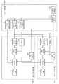
図1は、この発明の参考例1によるレーダ装置を示す構成図である。
図において、レーダ装置は、第1の送受信部100、第2の送受信部200、パルス制御部300からなる。第1の送受信部100および第2の送受信部200は、複数のパルス送信手段を構成するもので、それぞれが目標検出のためのパルスを送信する機能を有している。Reference Example 1
FIG. 1 is a block diagram showing a radar apparatus according toReference Example 1 of the present invention.
In the figure, the radar apparatus includes a first transmission /
第1の送受信部100は、アンテナ装置101、送信処理部102、パルス変調部103、発振部104、受信処理部105、移相器106からなる。アンテナ装置101は、送信や受信および送信方位の制御等の送信搬送波の位相制御を行うものである。尚、参考例1のアンテナ装置101は、ペンシルビームを送信するよう構成されている。送信処理部102は、送信電波の増幅および発振部104からの発振信号を合成して送信波を生成する機能部である。パルス変調部103は、パルス制御部300における共通パルス制御部302からの指示に基づき、送信パルスの発生・変調を行う機能部である。発振部104は、パルス制御部300における共通発振制御部303からの指示に従って発振信号を生成し、この発振信号を送信処理部102に出力する機能部である。受信処理部105は、アンテナ装置101で受信され、移相器106を介して位相制御された受信信号の処理を行う機能部である。移相器106は、パルス制御部300の共通位相制御部301からの制御に基づき送信処理部102から出力された送信波の位相制御を行う機能部である。The first transmission /
また、第2の送受信部200は、第1の送受信部100と同様の構成を備えている。即ち、アンテナ装置101〜移相器106を備えており、これらアンテナ装置201〜移相器206は、それぞれ、アンテナ装置101〜移相器106と同様の機能を有しているため、ここでの説明は省略する。 The second transmission /
パルス制御部300は、第1の送受信部100および第2の送受信部200のパルス送信時間間隔を、それぞれの間で相対的に変化させるよう制御する機能部であり、共通位相制御部301、共通パルス制御部302、共通発振制御部303、共通信号処理部304、共通表示制御部305を備えている。 The pulse control unit 300 is a functional unit that controls the pulse transmission time intervals of the first transmission /
共通位相制御部301は、共通信号処理部304の制御に基づきそれぞれの第1の送受信部100および第2の送受信部200に対しての送信波および受信波の位相の制御を行う機能部である。共通パルス制御部302は、二つのレーダのパルスを同一に制御するための機能部である。共通発振制御部303は、共通信号処理部304の指示に基づき同一の送信波を生成するために発振部104,204を制御する機能部である。共通信号処理部304は、受信信号から目標検出を行い、共通表示制御部305に表示データとして変換して送る機能や、共通位相制御部301や共通パルス制御部302の制御を行う機能を有するものである。また、共通表示制御部305は、共通信号処理部304の出力に基づいて、目標検出結果等の情報を表示するための制御部である。 The common
次に、このように構成された参考例1の動作について説明する。
共通信号処理部304は、第1の送受信部100および第2の送受信部200に対してパルスを制御するように共通パルス制御部302に対して指示を行う。共通パルス制御部302は、共通信号処理部304の指示に基づき、同じ変調方式で同一のパルスを発生させるようにパルス変調部103,203に対して指示を行う。パルス変調部103,203では、共通パルス制御部302の指示に基づいてパルスの生成・変調を行い、その結果を送信処理部102,202へ送る。送信処理部102,202においては、発振部104,204からの信号と発振部104,204からのパルス信号を合成させ、送信信号を生成し、移相器106,206に対して送信波を出力する。この際、発振部104,204は、共通発振制御部303からの制御により同一のタイミングで動作しているため、送信処理部102,202の送信波は全く同じものとなっている。Next, the operation ofReference Example 1 configured as described above will be described.
The common
また、共通発振制御部303は、共通信号処理部304の制御により発振部104,204が完全に同期動作をするように制御を行う。送信処理部102,202から出力された信号は、共通位相制御部301の制御に基づいて動作する移相器106,206により位相が制御されてそれぞれのアンテナ装置101,201にて送信される。このような動作により、第1の送受信部100と第2の送受信部200とから送信されるパルスの送信時間間隔(PRT)は、同一となっている。 In addition, the common
図2は、同一PRTの場合の説明図である。
図2(a)は、それぞれの第1の送受信部100および第2の送受信部200(図中、レーダ1およびレーダ2として示す)から同一の送信を同一PRTにて行った場合の送信パルスを示す図である。また、図2(b)は、この場合の位相を強めあう領域の説明図である。図2(a)に示すような送信を行った場合、図2(b)に示すように、お互いの送信位置から同じ距離の位置において位相を強めあう領域が発生する。これは、ペンシルビームで追尾した場合でもファンビームなどを用いて捜索した場合でも同一PRTにて送信する限りは図2(b)に示すように、常に同じ位置で送信波を強めあう領域が双曲線に示すように発生する。FIG. 2 is an explanatory diagram in the case of the same PRT.
FIG. 2A shows transmission pulses when the same transmission is performed from the first transmission /
このように目標検出(必要S/N確保)のための積分に必要な回数、同期された同位相である同一のPRTにてパルスが送信された後、共通信号処理部304は、異なるPRTにて送信を行うために共通パルス制御部302に対して異なるPRTにて送信制御を行う。共通パルス制御部302は、それぞれの第1の送受信部100および第2の送受信部200に対して、異なるPRTにて送信するようにパルス変調部103,203を制御する。制御されたパルス変調部103,203以降の動作は上述した同一のPRTの場合の送信制御と同じとなる。 Thus, after the pulses are transmitted by the same PRT having the same phase that is synchronized for the number of times necessary for integration for target detection (required necessary S / N), the common
図3は、PRTを変化させた場合の説明図である。
図示のように、第1の送受信部100(レーダ1)からの送信されるパルスのPRTは一定であるが、第2の送受信部200(レーダ2)におけるPRTは、PRT2,PRT3,PRT4,…とランダムとなっている。これにより、位相を強めあう領域が変化し、従って、目標物が見えたり見えなかったりという状態が発生するのを防止することができる。FIG. 3 is an explanatory diagram when the PRT is changed.
As shown in the figure, the PRT of the pulse transmitted from the first transceiver 100 (radar 1) is constant, but the PRT in the second transceiver 200 (radar 2) is PRT2, PRT3, PRT4,. And it is random. As a result, it is possible to prevent the occurrence of a state in which the region where the phases are strengthened changes, and thus the target is visible or invisible.
尚、図3に示す例では、第2の送受信部200のPRTをランダムに変化させると共に、パルス幅も変化させている。これにより、上述した目標物が見えたり見えなかったりという状態が発生するのを防止する効果をより高めることができるが、パルス幅を一定としてもよい。また、第1の送受信部100におけるPRTをランダムに変化させてもよく、このようにすれば、更に、位相を強めあう領域を複雑に変化させることができる。 In the example shown in FIG. 3, the PRT of the second transmission /
また、レーダ装置における受信動作は次のように行われる。
即ち、送信された電波は目標から反射し、アンテナ装置101,201にて受信される。受信された信号は、移相器106,206により位相が制御され、受信ビームの方位等が制御された後、受信処理部105,205に送られる。受信処理部105,205では受信された信号の復調、積分等の処理が行われる。復調などの処理が行われた受信信号は、共通信号処理部304にて目標検出などの処理が行われる。目標検出結果等の情報は共通表示制御部305にて表示される。The receiving operation in the radar apparatus is performed as follows.
That is, the transmitted radio wave is reflected from the target and received by the
以上のように、参考例1のレーダ装置によれば、送信したパルスが目標物で反射した信号を受信することにより、目標物の位置を検出するレーダ装置において、それぞれがパルスを送信する複数のパルス送信手段と、複数のパルス送信手段のパルス送信時間間隔を、それぞれの間で相対的に変化させるよう制御するパルス制御部を備えたので、目標物が見えたり見えなかったりという状態が発生するのを防止することができ、レーダ装置としての目標検出能力を向上させることができる。As described above, according to the radar apparatus ofReference Example 1, the radar apparatus that detects the position of the target object by receiving the signal in which the transmitted pulse is reflected by the target object has a plurality of pulses each transmitting a pulse. Since the pulse control unit that controls the pulse transmission unit and the pulse transmission time interval of the plurality of pulse transmission units to change relatively between each of them, a state in which the target is visible or invisible occurs. Can be prevented, and the target detection capability as a radar apparatus can be improved.
参考例2.
参考例2は、送信ビームとしてファンビームを用いたものであり、図面上の構成は参考例1と同様であるため、図1を援用して説明する。
参考例2におけるアンテナ装置101,201は、フェイズドアレイアンテナを用いている。また、移相器106,206は、DBF(デジタルビームフォーミング)の処理に対応した数(2次元DBFの場合は、フェイズドアレイの素子数分)の移相器を有している。このような構成により、広いビーム幅を持ち、捜索を行うのに有利なファンビームを実現している。その他の構成については、参考例1と同様である。また、基本的な動作についても、参考例1と同様であるため、ここでの説明は省略する。Reference Example 2
Reference Example 2 uses a fan beam as a transmission beam, and the configuration on the drawing is the same as that ofReference Example 1. Therefore, description will be made with reference to FIG.
The
以上のように、参考例2のレーダ装置によれば、複数のパルス送信手段は、フェーズドアレイアンテナを有し、ファンビームを送信するようにしたので、参考例1の効果に加えて、ファンビームを用いたことによる捜索時間の短縮が可能となる効果がある。As described above, according to the radar apparatus ofReference Example 2, the plurality of pulse transmission units have the phased array antenna and transmit the fan beam. In addition to the effects ofReference Example 1, the fan beam The search time can be shortened by using.
実施の形態1.
上記の参考例1,2では、PRTを変化させることにより位相を強めあう領域を固定した位置にならないように制御していたが、PRTは完全に同一でも送信タイミングをずらすことにより位相を強めあう領域を変化させることが可能であり、これを実施の形態1として次に示す。
In thereference examples 1 and 2 described above, control is performed so that the region where the phase is strengthened is not fixed by changing the PRT. However, even if the PRT is completely the same, the phase is strengthened by shifting the transmission timing. it is possible to change the area, shown below as afirst embodiment.
図面上の構成は、参考例1と同様であるため、図1を援用して説明する。
実施の形態1の共通発振制御部303では、各発振部104,204に対して、発振のタイミングを完全同期ではなく、二つの発振部104,204をある時間ずらして動作させるよう制御する構成となっている。即ち、実施の形態1のパルス制御部300は、第1の送受信部100および第2の送受信部200のうち、少なくとも一方の送受信部のパルス送信時間間隔として、パルスを送信しない時間である調整時間を任意のタイミングで複数挿入し、かつ、その調整時間をそれぞれ異なる値として制御するようにしている。これ以外の構成は、参考例1と同様である。Since the configuration on the drawing is the same as that of thereference example 1, FIG.
The common
図4は、PRTを同一とし、送信タイミングをずらした場合の送信パルスの説明図である。
図示のように、第1の送受信部100から送信されるパルスは、送信タイミングが一定となっているが、第2の送受信部200では、周期的に異なる調整時間(Tc1,Tc2,…)が挿入され、その結果、第2の送受信部200から送信されるパルスの送信タイミングは調整時間分変化するようになっている。FIG. 4 is an explanatory diagram of transmission pulses when the PRT is the same and the transmission timing is shifted.
As shown in the figure, the transmission timing of the pulses transmitted from the first transmission /
このように、それぞれの発振部104,204のずらす時間を適当に制御することにより、常に同一のエリアで位相を強めあうということはなくなり、時間的にみると、全領域で同じ程度の能力向上を図ることができる。 As described above, by appropriately controlling the shift time of the
以上のように、実施の形態1のレーダ装置によれば、パルス制御部は、複数のパルス送信手段において、パルスの送信時間間隔を同一かつ一定とすると共に、少なくとも一つのパルス送信手段において、パルスを送信しない時間である調整時間を任意のタイミングで複数挿入し、かつ、調整時間をそれぞれ異なる値として、複数のパルス送信手段のうち、少なくとも二つのパルス送信手段の間でパルス送信時間間隔を相対的に変化させるようにしたので、参考例1と同様に、目標物が見えたり見えなかったりという状態が発生するのを防止することができ、レーダ装置としての目標検出能力を向上させることができるという効果が得られる。As described above, according to the radar apparatus of thefirst embodiment, the pulse control unit,in a plurality of pulse transmissionmeans, the transmission time interval of the pulse with the same and constant,at leastone of the pulse transmittingmeans, A plurality of adjustment times, which are times when pulses are not transmitted, are inserted at arbitrary timings, and the adjustment times are set to different values, and a pulse transmission time interval is set between atleast two of the plurality of pulse transmission units. Since the relative change is made, as inReference Example 1, it is possible to prevent a situation in which the target is visible or invisible, and to improve the target detection capability as a radar apparatus. The effect that it can be obtained.
参考例3.
上記参考例1、2および実施の形態1は、受信処理以降およびパルス変調前を共通の構成としていたが、すべてが独立のレーダに対して必要なときにのみ2つのレーダの電波干渉領域を異なる位置に発生するように制御してもよく、これを参考例3として次に説明する。Reference Example 3
Although thereference examples 1and 2and the first embodiment have a common configuration after the reception process and before the pulse modulation, the radio wave interference areas of the two radars are different only when all are necessary for independent radars. It may be controlled so as to occur at the position, which will be described below as areference example 3 .
図5は、参考例3のレーダ装置の構成図である。
参考例3は、第1の送受信部100a、第2の送受信部200a、パルス制御部300aからなる。第1の送受信部100aおよび第2の送受信部200aは、複数のパルス送受信手段(複数のレーダ)を構成するもので、第1の送受信部100aは、アンテナ装置101〜移相器106、信号処理部107、表示制御部108を備えており、第2の送受信部200aは、アンテナ装置201〜移相器206、信号処理部207、表示制御部208を備えている。ここで、アンテナ装置101,201〜移相器106,206は、参考例1と同様である。また、信号処理部107(207)は、第1の送受信部100a(第2の送受信部200a)において、受信処理部105(205)からの受信信号から目標検出を行い、表示制御部108(208)に表示データとして変換して送る機能を有している。また、表示制御部108(208)は、信号処理部107(207)の出力に基づいて、目標検出結果等の情報を表示し、かつ、得られた情報をパルス制御部300aに送出する機能を有している。FIG. 5 is a configuration diagram of the radar apparatus ofReference Example 3 .
The reference example 3 includes a first transmission / reception unit 100a, a second transmission /
パルス制御部300aは、共通位相制御部301、共通パルス制御部302、共通発振制御部303、統合レーダ制御部306を有している。この統合レーダ制御部306は、表示制御部108(208)からの情報に基づいて、第1の送受信部100aと第2の送受信部200aの動作状態を常に監視し、必要な場合に参考例1,2および実施の形態1の動作を行うよう制御する機能を有するものである。The
ここで、必要な場合とは、第1の送受信部100aと第2の送受信部200aとを協働して動作させる場合をいう。即ち、参考例3では、第1及び第2の送受信部100a,200aは、その動作状態を統合レーダ制御部306によって監視しているが、それぞれ独立したレーダとして動作させることができるものであり、第1及び第2の送受信部100a,200aを独立したレーダとして動作させる場合(例えば、第1の送受信部100aの動作を停止して第2の送受信部200aのみを動作させる場合)には、上述したような制御は必要ではなく、これらを協働して動作させる場合に、統合レーダ制御部306は、第1及び第2の送受信部100a,200aに対して参考例1,2および実施の形態1に記載したような制御を行う。尚、共通位相制御部301〜共通発振制御部303の構成は参考例1と同様である。Here, the case where it is necessary refers to a case where the first transmission / reception unit 100a and the second transmission /
このように、参考例3では、独立した2つのレーダの動作状況を常に統合レーダ制御部306が監視しており、必要な場合に上記参考例1および2の動作を行うよう構成されている。このため、それぞれの表示制御部108,208は、常に第1の送受信部100aおよび第2の送受信部200aの動作状況を入手しており、入手した情報を統合レーダ制御部306に送る。統合レーダ制御部306は、得られた2つのレーダ動作状態から、一定の位置のみが強めあわないように、また、弱めあってしまうことがないように、共通位相制御部301、共通パルス制御部302、共通発振制御部303を制御する。即ち、必要に応じて、参考例1,2および実施の形態1の制御を行う。As described above, in thereference example 3 , the integrated
以上のように、参考例3のレーダ装置によれば、送信したパルスが目標物で反射した信号を受信することにより、目標物の位置を検出するレーダ装置において、それぞれがパルスを送受信する複数のパルス送受信手段と、複数のパルス送受信手段で受信した結果に基づいて、送信したパルスが特定の領域で強めあっているか、または、弱めあっているかを判定し、そうであった場合は、複数のパルス送受信手段が送信するパルスの送信時間間隔を、それぞれの間で相対的に変化させるよう制御するパルス制御部を備えたので、上記参考例1,2および実施の形態1と同様の効果が得られると共に、既存の独立したレーダに対して機能・構造を付加することでも実施することが可能となり、完全に新規に製造するよりもコストを抑えることが可能となる。As described above, according to the radar apparatus of thereference example 3 , the radar apparatus that detects the position of the target object by receiving the signal of the transmitted pulse reflected by the target object, Based on the results received by the pulse transmission / reception means and the plurality of pulse transmission / reception means, it is determined whether the transmitted pulses are strengthening or weakening in a specific region. Since the pulse control unit for controlling the transmission time interval of the pulses transmitted by the pulse transmission / reception means to relatively change between them is provided, the same effects as those of thefirst andsecond reference examples and thefirst embodiment can be obtained. In addition, it can be implemented by adding functions and structures to existing independent radars, which can reduce costs compared to completely new manufacturing. To become.
参考例4.
上記各参考例および実施の形態では、複数の送受信部のPRTを相対的に変化させることで、目標検出能力を向上させるようにしたが、複数の送受信部のPRTを異なるようにすることで、目標検出能力を向上させるようにしてもよく、これを参考例4として説明する。Reference Example 4
In each of the abovereference examples and embodiments, the target detection capability is improved by relatively changing the PRTs of the plurality of transmission / reception units, but by making the PRTs of the plurality of transmission / reception units different, The target detection capability may be improved, which will be described asReference Example 4 .
参考例4における図面上の構成は、参考例1と同様であるため、図1を援用して説明する。参考例4におけるパルス制御部300は、第1の送受信部100に対しては通常のPRTで送信するよう制御を行い、第2の送受信部200に対しては、PRTを細かくするよう制御する。その他の各構成については参考例1と同様である。Since the configuration of thereference example 4 on the drawing is the same as that of thereference example 1, it will be described with reference to FIG. The pulse control unit 300 inReference Example 4 controls the first transmission /
図6は、それぞれの送受信部のPRTを示す説明図である。
図中、(a)は第1の送受信部100のパルス送信時間間隔(PRT1)、(b)は第2の送受信部200のパルス送信時間間隔(PRT2)を示している。図示のように、PRT1>PRT2であり、このようなパルスの送出間隔とすることにより、強めあう領域を細かくすることができる。尚、第1の送受信部100および第2の送受信部200のパルス幅においても、第1の送受信部100のパルス幅を太く、第2の送受信部200のパルス幅を短くしている。これにより、強めあう領域を更に細かくすることが可能であるが、パルス幅が同一であっても、PRT1>PRT2であれば、強めあう領域を細かくするという効果を得ることができる。FIG. 6 is an explanatory diagram showing the PRT of each transmission / reception unit.
In the figure, (a) shows the pulse transmission time interval (PRT1) of the first transmission /
以上のように、参考例4のレーダ装置によれば、パルス制御部は、複数のパルス送信手段がそれぞれ異なるパルス送信時間間隔となるよう制御を行うようにしたので、目標が見える可能性のある領域を増やすことができ、その結果、レーダ装置としての目標検出性能を向上させることができる。As described above, according to the radar apparatus ofReference Example 4 , the pulse control unit performs control so that the plurality of pulse transmission units have different pulse transmission time intervals, so the target may be visible. The area can be increased, and as a result, the target detection performance as a radar apparatus can be improved.
参考例5.
上記各参考例および実施の形態では、目標検出性能を向上させるため、送信波を強めあう領域を固定させないようにしたが、例えば、追尾専用ビームといったレーダで、目標の位置が特定できる場合は、その目標の位置で必ず送信波を強めあうよう制御してもよく、これを参考例5として説明する。Reference Example 5
In each of the abovereference examples and embodiments, in order to improve the target detection performance, the region that strengthens the transmission wave is not fixed.For example, when the target position can be specified by a radar such as a tracking-dedicated beam, Control may be performed such that transmission waves are always strengthened at the target position, which will be described asReference Example 5 .
図7は、参考例5の構成図である。
参考例5におけるパルス制御部300bは、共通位相制御部301、共通パルス制御部302、共通発振制御部303、共通信号処理部304、共通表示制御部305、目標位置判定部307からなる。目標位置判定部307は、共通信号処理部304の出力から、ある1目標に対して目標の位置を入手し、この位置に対して送信波が必ず強めあうように、共通位相制御部301、共通パルス制御部302、共通発振制御部303における送信タイミングや位相等を制御する機能を有している。これ以外の第1の送受信部100bおよび第2の送受信部200bの構成は、参考例1と同様であるため、ここでの説明は省略する。FIG. 7 is a configuration diagram ofReference Example 5 .
The
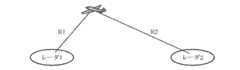
図8は、目標と第1の送受信部100b(レーダ1)および第2の送受信部200b(レーダ2)との位置関係を示す説明図である。
目標と第1の送受信部100bとの距離をR1、目標と第2の送受信部200bとの距離をR2とし、これらの距離R1,R2は、目標位置判定部307にて測定済みであるとする。尚、この測定方法としては、参考例1,2および実施の形態1と同様の動作を行うことで距離R1,R2を求めたり、あるいは捜索用のレーダ装置を別途用意し、このレーダ装置から値を取得するようにしてもよい。FIG. 8 is an explanatory diagram showing the positional relationship between the target and the first transmission /
Assume that the distance between the target and the first transmission /
今、第1の送受信部100bと第2の送受信部200bとのパルス幅やPRTは同一(同一諸元)とし、距離R1におけるパルス到達時間はPRTの2倍、距離R2におけるパルス到達時間はPRTの3倍であるとする。
図9は、この状態を示す説明図である。
このような場合、目標に到達するタイミングを同時にすれば、パルス内の送信波は(同一諸元であるため位相も同期するため)、必ず強めあうことになる。従って、第2の送受信部200bからは、第1の送受信部100bの送信タイミングよりも必ず1PRT先に送信することにより必ず強めあうことが可能となる。Now, the pulse width and PRT of the first transmission /
FIG. 9 is an explanatory diagram showing this state.
In such a case, if the timing to reach the target is set at the same time, the transmission waves in the pulse will always be strengthened (because they have the same specifications and the phase is synchronized). Therefore, the second transmission /
つまり、二つの第1の送受信部100bと第2の送受信部200bの距離をR1,R2、PRTを同一とした場合、
(R2のパルス到達時間−R1のパルス到達時間)/C 但し、Cは光速を示す
の時間だけ先に第2の送受信部200bが送信を始める必要がある(R1<R2)。That is, when the distance between the two first transmission /
(R2 pulse arrival time-R1 pulse arrival time) / C However, C needs to start transmission by the second transmitting / receiving
また、このような目標までの距離に応じて送信波が必ず強めあう制御を行った後、所定時間が経過し、目標までの距離が変化した場合は、その距離に応じて、上記と同様の処理を行う。ここで、変化した距離の求め方としては、それまでの目標の位置に基づいて次の目標位置を推定する方法や、再度、参考例1,2および実施の形態1の動作を行って求めてもよい。即ち、参考例1,2および実施の形態1の動作によって現在位置を求める場合は、所定時間毎に、送信波を強めあう領域を固定させない制御を行って目標への位置を測定する捜索モードと、この捜索モードで取得した目標への距離に基づいて、目標の位置で送信波が必ず強めあうよう制御する追尾モードを繰り返すことになる。尚、次の目標位置を求める方法はレーダ装置において公知であるため、ここでの説明は省略する。In addition, after performing a control in which the transmission waves are always intensified according to the distance to the target, when the predetermined time has elapsed and the distance to the target has changed, the same as above according to the distance. Process. Here, as the method of obtaining the altered distance, so far based on the position of the target and method for estimating a next target position, again, it is determined by performing the operation ofReference Examples 1 and 2 and
以上のように、参考例5のレーダ装置によれば、送信したパルスが目標物で反射した信号を受信することにより、目標物の位置を検出するレーダ装置において、それぞれがパルスを送信する複数のパルス送信手段と、目標物の位置を判定する目標位置判定部を有し、目標位置判定部で判定された目標物の位置と、複数のパルス送信手段におけるパルス送信位置とのそれぞれの距離に基づき、送信されたパルスが目標物の位置で強めあうよう、パルス送信手段のパルス送信タイミングを制御するパルス制御部とを備えたので、単一のレーダ装置で送受信を行う場合に比べてより得られる反射を大きくすることができ、S/Nが大きくなるため、単体レーダで動作するよりも目標検出能力を向上させることができる。As described above, according to the radar apparatus of thereference example 5, in the radar apparatus that detects the position of the target object by receiving the signal in which the transmitted pulse is reflected by the target object, each of the plurality of transmitting pulse signals is transmitted. A pulse transmission unit and a target position determination unit for determining the position of the target, based on the distance between the position of the target determined by the target position determination unit and the pulse transmission position in the plurality of pulse transmission units Since it has a pulse control unit that controls the pulse transmission timing of the pulse transmission means so that the transmitted pulses are strengthened at the position of the target, it can be obtained more than when transmitting and receiving with a single radar device Since the reflection can be increased and the S / N is increased, the target detection capability can be improved as compared with the case of operating with a single radar.
尚、上記各参考例および実施の形態では、複数のパルス送信手段として、二つの場合を説明したが、これに限定されるものではなく、三つ以上のパルス送信手段に対して制御するようにしてもよい。In each of the abovereference examples and embodiments, two cases have been described as the plurality of pulse transmission means. However, the present invention is not limited to this, and three or more pulse transmission means are controlled. May be.
100,100b 第1の送受信部(パルス送信手段)、200,200b 第2の送受信部(パルス送信手段)、100a 第1の送受信部(パルス送受信手段)、200a 第2の送受信部(パルス送受信手段)、300,300a,300b パルス制御部、307 目標位置判定部。 100, 100b first transmission / reception unit (pulse transmission means), 200, 200b second transmission / reception unit (pulse transmission means), 100a first transmission / reception unit (pulse transmission / reception means), 200a second transmission / reception unit (pulse transmission / reception means) ), 300, 300a, 300b Pulse control unit, 307 Target position determination unit.
Claims (2)
Translated fromJapanese前記パルスを送信する複数のパルス送信手段と、
前記複数のパルス送信手段において、パルスの送信時間間隔を同一かつ一定とすると共に、少なくとも一つのパルス送信手段において、パルスを送信しない時間である調整時間を任意のタイミングで複数挿入し、かつ、当該調整時間をそれぞれ異なる値として、前記複数のパルス送信手段のうち、少なくとも二つのパルス送信手段の間でパルス送信時間間隔を相対的に変化させるよう制御するパルス制御部とを備えたレーダ装置。In the radar device that detects the position of the target by receiving the signal that the transmitted pulse reflects from the target,
A plurality of pulse transmitting means for transmitting the pulses;
In the plurality of pulse transmittingmeans, a transmission time interval of the pulse with the same and constant,at leastone of the pulse transmittingmeans, the adjustment time which is a time not to transmit a pulse plurality inserted at an arbitrary timing, and, A radar apparatus comprising: a pulse control unit that controls the adjustment time so that the pulse transmission time interval is relatively changed between atleast two pulse transmission unitsamong the plurality of pulse transmission units with different values.
Priority Applications (1)
| Application Number | Priority Date | Filing Date | Title |
|---|---|---|---|
| JP2005180868AJP4916678B2 (en) | 2005-06-21 | 2005-06-21 | Radar equipment |
Applications Claiming Priority (1)
| Application Number | Priority Date | Filing Date | Title |
|---|---|---|---|
| JP2005180868AJP4916678B2 (en) | 2005-06-21 | 2005-06-21 | Radar equipment |
Publications (2)
| Publication Number | Publication Date |
|---|---|
| JP2007003228A JP2007003228A (en) | 2007-01-11 |
| JP4916678B2true JP4916678B2 (en) | 2012-04-18 |
Family
ID=37689020
Family Applications (1)
| Application Number | Title | Priority Date | Filing Date |
|---|---|---|---|
| JP2005180868AExpired - LifetimeJP4916678B2 (en) | 2005-06-21 | 2005-06-21 | Radar equipment |
Country Status (1)
| Country | Link |
|---|---|
| JP (1) | JP4916678B2 (en) |
Families Citing this family (3)
| Publication number | Priority date | Publication date | Assignee | Title |
|---|---|---|---|---|
| JP2013238477A (en)* | 2012-05-15 | 2013-11-28 | Furukawa Electric Co Ltd:The | Radar device |
| KR101711932B1 (en)* | 2014-11-14 | 2017-03-03 | 삼성중공업 주식회사 | System and method for marine radar control |
| JP7112829B2 (en)* | 2017-01-27 | 2022-08-04 | 古河電気工業株式会社 | RADAR DEVICE, CONTROL METHOD FOR RADAR DEVICE, AND RADAR SYSTEM |
Family Cites Families (6)
| Publication number | Priority date | Publication date | Assignee | Title |
|---|---|---|---|---|
| JPS5245479B2 (en)* | 1972-02-19 | 1977-11-16 | ||
| JPS5432091A (en)* | 1977-08-15 | 1979-03-09 | Nec Corp | Radar interference eleimenating system |
| JPH01307688A (en)* | 1988-06-06 | 1989-12-12 | Tech Res & Dev Inst Of Japan Def Agency | integrated detection device |
| JPH0271185A (en)* | 1988-09-07 | 1990-03-09 | Mitsubishi Electric Corp | Radar device |
| JP2576249B2 (en)* | 1990-01-30 | 1997-01-29 | 三菱電機株式会社 | Phased array radar beam management method and apparatus |
| JP3763000B2 (en)* | 2003-09-17 | 2006-04-05 | 防衛庁技術研究本部長 | Radar equipment |
- 2005
- 2005-06-21JPJP2005180868Apatent/JP4916678B2/ennot_activeExpired - Lifetime
Also Published As
| Publication number | Publication date |
|---|---|
| JP2007003228A (en) | 2007-01-11 |
Similar Documents
| Publication | Publication Date | Title |
|---|---|---|
| JP5093298B2 (en) | Direction detection device | |
| JP4656144B2 (en) | Radar equipment | |
| JPH08136647A (en) | FM-CW system multi-beam radar device | |
| JP2007189436A (en) | Inter-vehicle communication device | |
| JP6019795B2 (en) | Radar apparatus, target data acquisition method, and target tracking system | |
| JPH01153989A (en) | Phased array radar device | |
| CN111819459B (en) | Method for unambiguously determining the speed of an object on a radar measurement system | |
| US20040189513A1 (en) | Transmit-receive FM-CW radar apparatus | |
| US9285457B2 (en) | High-accuracy detection in collaborative tracking systems | |
| JP4615542B2 (en) | Millimeter wave radar equipment | |
| JP2011257376A (en) | Rader device | |
| WO2019059217A1 (en) | Radar device | |
| JP4916678B2 (en) | Radar equipment | |
| JP2008107158A (en) | Automotive radar equipment | |
| JP2010156708A (en) | On-vehicle millimeter-wave radar device | |
| JPH11258340A (en) | Radar transceiver | |
| JP2006242844A (en) | Radar apparatus and transmission beam control method | |
| JP2003248056A (en) | Multi-static radar device | |
| JP4294665B2 (en) | Millimeter wave radar equipment | |
| JP6385278B2 (en) | Radar apparatus and radar image display method | |
| JPH0666930A (en) | Radar apparatus | |
| JP2005091174A (en) | Radar equipment | |
| JPH11352224A (en) | Radar equipment | |
| JP2964947B2 (en) | Time-division radar system | |
| JPH0792258A (en) | Vehicle radar device |
Legal Events
| Date | Code | Title | Description |
|---|---|---|---|
| RD04 | Notification of resignation of power of attorney | Free format text:JAPANESE INTERMEDIATE CODE: A7424 Effective date:20071005 | |
| A621 | Written request for application examination | Free format text:JAPANESE INTERMEDIATE CODE: A621 Effective date:20080109 | |
| RD04 | Notification of resignation of power of attorney | Free format text:JAPANESE INTERMEDIATE CODE: A7424 Effective date:20080624 | |
| A977 | Report on retrieval | Free format text:JAPANESE INTERMEDIATE CODE: A971007 Effective date:20091201 | |
| A131 | Notification of reasons for refusal | Free format text:JAPANESE INTERMEDIATE CODE: A131 Effective date:20091208 | |
| A521 | Request for written amendment filed | Free format text:JAPANESE INTERMEDIATE CODE: A523 Effective date:20100203 | |
| A131 | Notification of reasons for refusal | Free format text:JAPANESE INTERMEDIATE CODE: A131 Effective date:20100629 | |
| A521 | Request for written amendment filed | Free format text:JAPANESE INTERMEDIATE CODE: A523 Effective date:20100826 | |
| A131 | Notification of reasons for refusal | Free format text:JAPANESE INTERMEDIATE CODE: A131 Effective date:20110628 | |
| A521 | Request for written amendment filed | Free format text:JAPANESE INTERMEDIATE CODE: A523 Effective date:20110803 | |
| TRDD | Decision of grant or rejection written | ||
| A01 | Written decision to grant a patent or to grant a registration (utility model) | Free format text:JAPANESE INTERMEDIATE CODE: A01 Effective date:20120117 | |
| A01 | Written decision to grant a patent or to grant a registration (utility model) | Free format text:JAPANESE INTERMEDIATE CODE: A01 | |
| A61 | First payment of annual fees (during grant procedure) | Free format text:JAPANESE INTERMEDIATE CODE: A61 Effective date:20120125 | |
| FPAY | Renewal fee payment (event date is renewal date of database) | Free format text:PAYMENT UNTIL: 20150203 Year of fee payment:3 | |
| R150 | Certificate of patent or registration of utility model | Ref document number:4916678 Country of ref document:JP Free format text:JAPANESE INTERMEDIATE CODE: R150 | |
| R250 | Receipt of annual fees | Free format text:JAPANESE INTERMEDIATE CODE: R250 | |
| R250 | Receipt of annual fees | Free format text:JAPANESE INTERMEDIATE CODE: R250 | |
| R250 | Receipt of annual fees | Free format text:JAPANESE INTERMEDIATE CODE: R250 | |
| R250 | Receipt of annual fees | Free format text:JAPANESE INTERMEDIATE CODE: R250 | |
| R250 | Receipt of annual fees | Free format text:JAPANESE INTERMEDIATE CODE: R250 | |
| R250 | Receipt of annual fees | Free format text:JAPANESE INTERMEDIATE CODE: R250 | |
| R250 | Receipt of annual fees | Free format text:JAPANESE INTERMEDIATE CODE: R250 | |
| R250 | Receipt of annual fees | Free format text:JAPANESE INTERMEDIATE CODE: R250 | |
| R250 | Receipt of annual fees | Free format text:JAPANESE INTERMEDIATE CODE: R250 | |
| R250 | Receipt of annual fees | Free format text:JAPANESE INTERMEDIATE CODE: R250 | |
| EXPY | Cancellation because of completion of term |