JP4916011B2 - Master / slave manipulator system - Google Patents
Master / slave manipulator systemDownload PDFInfo
- Publication number
- JP4916011B2 JP4916011B2JP2007072447AJP2007072447AJP4916011B2JP 4916011 B2JP4916011 B2JP 4916011B2JP 2007072447 AJP2007072447 AJP 2007072447AJP 2007072447 AJP2007072447 AJP 2007072447AJP 4916011 B2JP4916011 B2JP 4916011B2
- Authority
- JP
- Japan
- Prior art keywords
- manipulator
- visual field
- slave
- master
- mode
- Prior art date
- Legal status (The legal status is an assumption and is not a legal conclusion. Google has not performed a legal analysis and makes no representation as to the accuracy of the status listed.)
- Expired - Fee Related
Links
Images


Classifications
- G—PHYSICS
- G05—CONTROLLING; REGULATING
- G05B—CONTROL OR REGULATING SYSTEMS IN GENERAL; FUNCTIONAL ELEMENTS OF SUCH SYSTEMS; MONITORING OR TESTING ARRANGEMENTS FOR SUCH SYSTEMS OR ELEMENTS
- G05B19/00—Programme-control systems
- G05B19/02—Programme-control systems electric
- G05B19/42—Recording and playback systems, i.e. in which the programme is recorded from a cycle of operations, e.g. the cycle of operations being manually controlled, after which this record is played back on the same machine
- G05B19/427—Teaching successive positions by tracking the position of a joystick or handle to control the positioning servo of the tool head, leader-follower control
- A—HUMAN NECESSITIES
- A61—MEDICAL OR VETERINARY SCIENCE; HYGIENE
- A61B—DIAGNOSIS; SURGERY; IDENTIFICATION
- A61B34/00—Computer-aided surgery; Manipulators or robots specially adapted for use in surgery
- A61B34/30—Surgical robots
- A—HUMAN NECESSITIES
- A61—MEDICAL OR VETERINARY SCIENCE; HYGIENE
- A61B—DIAGNOSIS; SURGERY; IDENTIFICATION
- A61B34/00—Computer-aided surgery; Manipulators or robots specially adapted for use in surgery
- A61B34/30—Surgical robots
- A61B34/37—Leader-follower robots
- B—PERFORMING OPERATIONS; TRANSPORTING
- B25—HAND TOOLS; PORTABLE POWER-DRIVEN TOOLS; MANIPULATORS
- B25J—MANIPULATORS; CHAMBERS PROVIDED WITH MANIPULATION DEVICES
- B25J9/00—Programme-controlled manipulators
- B25J9/16—Programme controls
- B25J9/1679—Programme controls characterised by the tasks executed
- B25J9/1689—Teleoperation
- A—HUMAN NECESSITIES
- A61—MEDICAL OR VETERINARY SCIENCE; HYGIENE
- A61B—DIAGNOSIS; SURGERY; IDENTIFICATION
- A61B90/00—Instruments, implements or accessories specially adapted for surgery or diagnosis and not covered by any of the groups A61B1/00 - A61B50/00, e.g. for luxation treatment or for protecting wound edges
- A61B90/36—Image-producing devices or illumination devices not otherwise provided for
- A61B90/361—Image-producing devices, e.g. surgical cameras
- A—HUMAN NECESSITIES
- A61—MEDICAL OR VETERINARY SCIENCE; HYGIENE
- A61B—DIAGNOSIS; SURGERY; IDENTIFICATION
- A61B90/00—Instruments, implements or accessories specially adapted for surgery or diagnosis and not covered by any of the groups A61B1/00 - A61B50/00, e.g. for luxation treatment or for protecting wound edges
- A61B90/36—Image-producing devices or illumination devices not otherwise provided for
- A61B90/37—Surgical systems with images on a monitor during operation
- G—PHYSICS
- G05—CONTROLLING; REGULATING
- G05B—CONTROL OR REGULATING SYSTEMS IN GENERAL; FUNCTIONAL ELEMENTS OF SUCH SYSTEMS; MONITORING OR TESTING ARRANGEMENTS FOR SUCH SYSTEMS OR ELEMENTS
- G05B2219/00—Program-control systems
- G05B2219/30—Nc systems
- G05B2219/39—Robotics, robotics to robotics hand
- G05B2219/39389—Laparoscopic surgery, camera on center of operated part, view around, scale
- G—PHYSICS
- G05—CONTROLLING; REGULATING
- G05B—CONTROL OR REGULATING SYSTEMS IN GENERAL; FUNCTIONAL ELEMENTS OF SUCH SYSTEMS; MONITORING OR TESTING ARRANGEMENTS FOR SUCH SYSTEMS OR ELEMENTS
- G05B2219/00—Program-control systems
- G05B2219/30—Nc systems
- G05B2219/40—Robotics, robotics mapping to robotics vision
- G05B2219/40617—Agile eye, control position of camera, active vision, pan-tilt camera, follow object
Landscapes
- Engineering & Computer Science (AREA)
- Health & Medical Sciences (AREA)
- Life Sciences & Earth Sciences (AREA)
- Robotics (AREA)
- Surgery (AREA)
- Medical Informatics (AREA)
- Public Health (AREA)
- Heart & Thoracic Surgery (AREA)
- Nuclear Medicine, Radiotherapy & Molecular Imaging (AREA)
- Molecular Biology (AREA)
- Animal Behavior & Ethology (AREA)
- General Health & Medical Sciences (AREA)
- Biomedical Technology (AREA)
- Veterinary Medicine (AREA)
- Mechanical Engineering (AREA)
- Physics & Mathematics (AREA)
- General Physics & Mathematics (AREA)
- Automation & Control Theory (AREA)
- Manipulator (AREA)
Description
Translated fromJapanese本発明は、マスタ・スレーブ式マニピュレータシステムに関する。 The present invention relates to a master / slave manipulator system.
操作手段をオペレ一夕が操作し、その操作に従ってスレーブマニピュレータが動作するマスタ・スレーブ式マニピュレータシステムが数多く開発されている。対象物およびスレーブマニピュレータを観察手段であるカメラで見ながら、操作手段によりスレーブマニピュレータを操作する時、スレーブマニピュレータだけでなく、カメラ自体も操作したい場合がある。 Numerous master / slave manipulator systems have been developed in which the operator operates the operating means and the slave manipulator operates according to the operation. When operating the slave manipulator with the operation means while viewing the object and the slave manipulator with the camera as the observation means, there are cases where it is desired to operate not only the slave manipulator but also the camera itself.
操作しているスレーブマニピュレータが一台の場合は、右手でスレーブマニピュレータに対応した操作手段を操作し、左手でカメラに対応した操作手段を動かすといった方法がある。また、スレーブマニピュレータ2台をそれぞれに対応した操作手段2台で両手を使って操作している場合は、その操作手段から手を離して、カメラに対応した操作手段を操作するシステムが開発されている。 In the case where one slave manipulator is operated, there is a method in which an operating means corresponding to the slave manipulator is operated with the right hand and an operating means corresponding to the camera is moved with the left hand. In addition, when two slave manipulators are operated using two hands corresponding to each of the two manipulators, a system has been developed to operate the operation means corresponding to the camera by releasing the hands. Yes.
しかし、操作スピードが求められる場合や、操作中の操作手段から手を離したくない場合などがある。その場合には、操作中の手を使わないでカメラを動かす手段として、特開平7−328016号公報(特許文献1)、特開平7−328971号公報(特許文献2)などが案出されている。特許文献1では、ヘッドマウントディスプレイで画像を提供しながら、ヘッドマウントディスプレイの位置を検出し、頭の動きに応じてカメラ視野を変えている。特許文献2では、マニピュレータにカメラを取り付けることにより、マニピレータを自動的に作業に適正な位置に移動させて作業をスムーズに遂行し得るTVカメラ付マニピュレータを開示している
また、カメラによって撮像され映像内での作用具の動きと、操作入力装置の関係を対応させる手段として、特許文献1、特許3766805号公報(特許文献3)が案出されている。特許文献1では、カメラ画像を表示する画面上に、マニピュレータの動作座標系をスーパーインポーズさせて、操作支援を行うことを開示している。特許文献3では、画像上に表示されるマニピュレータの動作方向と、操作入力装置の動作方向を一致させることを開示している。However, there are cases where the operation speed is required, and there is a case where it is not desired to release the hand from the operation means being operated. In that case, Japanese Patent Laid-Open No. 7-328016 (Patent Document 1), Japanese Patent Laid-Open No. 7-328971 (Patent Document 2), etc. have been devised as means for moving the camera without using the operating hand. Yes. In
上述したように、カメラを用いたマスタ・スレーブマニピュレータシステムでは、カメラの視野に制限があるため、作業対象の移動や、状況の変化などによりカメラの視野を変更したいことが多々起こる。 As described above, in a master / slave manipulator system using a camera, there is a limit to the field of view of the camera.
しかし、カメラの位置を変更する際、従来の技術では、スレーブマニピュレータ作業部が画面から外れてしまうことや、視野変更後、表示手段上に映されるスレーブマニピュレータ作業部の位置姿勢と操作手段の位置姿勢の一致が考慮されず、視野変更後のマスタ・スレーブ操作が操作しづらいことがあるといった課題があった。 However, when changing the position of the camera, in the conventional technique, the slave manipulator working unit is off the screen, or after changing the field of view, the position and orientation of the slave manipulator working unit displayed on the display unit and the operation unit There is a problem that the matching of the position and orientation is not taken into account, and the master / slave operation after changing the field of view may be difficult to operate.
また、GUI(Graphical User Interface)上のポインタを、マウスにより動かす際、マウスの操作範囲の限界に達したときにマウスを空中に持ち上げて、操作しやすい位置にマウスを動かしてから、GUIのポインタを再び動かし始めるといった動作(以下、これをクラッチ操作と呼ぶ)を操作手段でも行えるようにすることが望まれる。つまり、操作手段の動作限界範囲の問題で、スレーブマニピュレータの位置はそのままで、操作手段を動かしやすい位置に戻すというようなクラッチ操作を行うことが望まれる。このようなクラッチ操作を行った場合、表示手段上に映されるスレーブマニピュレータの位置姿勢と操作手段の位置姿勢とがずれ、それにより、操作手段で操作する方向とマニピュレータが動作する方向とがずれるという問題が生ずる。この動作方向のずれは、操作者の負担を大きくし、複雑な操作を行うことを困難とさせてしまう。 When the pointer on the GUI (Graphical User Interface) is moved by the mouse, when the limit of the mouse operation range is reached, the mouse is lifted into the air and moved to a position where it can be easily operated. It is desired that an operation such as starting to move again (hereinafter referred to as clutch operation) can also be performed by the operation means. That is, it is desirable to perform a clutch operation such as returning the operation means to a position where the operation means can be easily moved without changing the position of the slave manipulator due to the problem of the operation limit range of the operation means. When such a clutch operation is performed, the position and orientation of the slave manipulator displayed on the display means and the position and orientation of the operation means are deviated from each other, so that the direction operated by the operation means and the direction in which the manipulator operates are shifted. The problem arises. This shift in the operation direction increases the burden on the operator and makes it difficult to perform complicated operations.
さらに、視野を変更している間、作業を実行するスレーブマニピュレータが停止してしまうことにより、作業効率が悪化し、作業時間が延びるという課題もある。特に、近年の医療分野では、患者の体への負担を低減するために、患者の体に小さな穴を開け、そこから術具や内視鏡を挿入して、患部や術具の様子を内視鏡画像で観察しながら、治療を行う低侵襲手術が広まっている。スレーブマニピュレータを用いる手術においても、同様に小さな切開部からスレーブマニピュレータの術具を挿入して、内視鏡画像を基にして治療行為を行う。このような状況下においては、自由度が制限されるため、操作者に負担をかけるような操作方法は好ましくなく、操作者の意思を正確に反映したスレーブマニピュレータの動作を容易に実現できることが望ましい。 Furthermore, while the view field is changed, the slave manipulator that performs the work stops, so that the work efficiency is deteriorated and the work time is extended. Particularly in the medical field in recent years, in order to reduce the burden on the patient's body, a small hole is made in the patient's body, and a surgical tool or endoscope is inserted from there, so that the affected part or surgical tool can be seen. Minimally invasive surgery that treats patients while observing them with endoscopic images has become widespread. Similarly, in the operation using the slave manipulator, the surgical manipulator of the slave manipulator is similarly inserted from a small incision portion, and the therapeutic action is performed based on the endoscopic image. Under such circumstances, since the degree of freedom is limited, an operation method that places a burden on the operator is not preferable, and it is desirable that the operation of the slave manipulator that accurately reflects the operator's intention can be easily realized. .
上述した特許文献1では、両手を使わずにカメラの視野を変えているが、視野変更後のマスタを持っている手の位置姿勢と画面上に見えるスレーブマニピュレータ作業部との位置姿勢のずれについては考慮されていない。 In
上述した特許文献2では、スレーブマニピュレータをカメラが常に映すように考えられているが、表示手段に映されたスレーブマニピュレータと操作手段の関係については考慮されていない。 In
上述した特許文献3では、手術用マニピュレータと遠隔操作手段との動作方向を一致させることを開示しているが、内視鏡画像を動かす手段およびその際の表示画像上のマニピュレータの動作方向と操作手段の操作方法を一致させることについては言及されていない。また、クラッチ操作についても考慮されていない。 Patent Document 3 described above discloses that the operation directions of the surgical manipulator and the remote operation means are made to coincide with each other. However, the movement direction of the endoscope image and the operation direction and operation of the manipulator on the display image at that time are disclosed. There is no mention of matching the method of operation of the means. Further, the clutch operation is not taken into consideration.
つまり、これら従来技術では、カメラの視野を変更したり、クラッチ操作を起こしたりした際には、カメラによって撮影されるスレーブマニピュレータ作業部の姿勢と操作手段の姿勢に相違が生じて操作がしづらいといった問題があった。 In other words, in these conventional techniques, when the field of view of the camera is changed or a clutch operation is performed, the posture of the slave manipulator working unit photographed by the camera is different from the posture of the operation means, and the operation is difficult. There was a problem.
本発明の目的は、クラッチ操作を行ってもあるいはカメラ視野を移動させても、カメラ画像上に映されるスレーブマニピュレータ作業部の位置姿勢と操作手段の位置姿勢との関係が保たれ、直感的に操作手段を操作することが可能なマスタ・スレーブ動作に移行できるマスタ・スレーブ式マニピュレータシステムを提供することにある。 The object of the present invention is to maintain the relationship between the position and orientation of the slave manipulator working unit displayed on the camera image and the position and orientation of the operation means regardless of whether the clutch operation is performed or the camera field of view is moved. Another object of the present invention is to provide a master / slave manipulator system capable of shifting to a master / slave operation capable of operating an operating means.
即ち、本発明の第1の目的は、クラッチ操作を行って操作手段の位置を動かしても、表示手段を見ながら操作手段を容易に操作でき、安全性、作業性および操作性に優れたマスタ・スレーブ式マニピュレータシステムを提供することである。 That is, the first object of the present invention is to provide a master that is easy to operate the operating means while looking at the display means even if the position of the operating means is moved by performing a clutch operation, and is excellent in safety, workability and operability. • To provide a slave manipulator system.
本発明の第2の目的は、クラッチ操作を行っても、カメラの視野を変更しても、表示手段を見ながら操作手段を容易に操作でき、安全性、作業性および操作性に優れたマスタ・スレーブ式マニピュレータシステムを提供することである。Thesecond object of the present invention is to provide a master having excellent safety, workability, and operability, regardless of whether the clutch is operated or the field of view of the camera is changed and the operation means can be easily operated while looking at the display means. • To provide a slave manipulator system.
本発明の第3の目的は、カメラの視野を変更している間も、操作者に混乱をもたらすことなく、マニピュレータの操作を可能とし、操作者の意図に応じた視野変更とマニピュレータの操作を同時に実行できるようにすることにより、安全性、作業性および操作性に優れたマスタ・スレーブ式マニピュレータシステムを提供することである。Thethird object of the present invention is to enable manipulator operation without changing the operator's field of view while changing the camera's field of view, and to change the field of view and manipulator operation according to the operator's intention. It is to provide a master / slave manipulator system that is excellent in safety, workability, and operability by enabling simultaneous execution.
前記第1の目的を達成するための本発明の第1の態様は、操作指令を生成するために操作する操作手段と、その操作指令を読み取り第1の制御指令を送る操作手段制御部と、前記第1の制御指令に基づきスレーブマニピュレータの各関節を制御するための第2の制御指令を出力するマニピュレータ制御部と、前記第2の制御指令に基づいて動作する前記スレーブマニピュレータと、前記スレーブマニピュレータの動作を観察する観察手段と、
前記観察手段の視野を変更する視野変更手段と、前記視野変更手段を制御する視野変更制御部と、前記観察手段で観察したマニピュレータの映像を画面に表示する表示手段とを備えたマニピュレータシステムにおいて、前記スレーブマニピュレータを制御するマスタ・スレーブモードと、前記操作手段から前記スレーブマニピュレータへの操作指令の伝達を切断して前記操作手段を任意の位置姿勢に移動する観察手段視野追従クラッチモードとを切り替えるモード切替手段と、前記モード切替手段の信号を読み取り前記操作手段制御部にモード信号を送る切替器制御部と、前記操作手段制御部で読み取った観察手段視野追従クラッチモード時の操作指令に基づき、前記表示手段に表示されるスレーブマニピュレータの映像の動作方向と前記操作手段の操作方向とを一致させるように、前記マニピュレータ制御部に第3の制御指令を送ると共に前記視野変更制御部に第4の制御指令を送る視野変換部とを備えたことにある。According to a first aspect of the present invention for achieving the first object, an operation means for operating to generate an operation command, an operation means controller for reading the operation command and sending a first control command, A manipulator controller that outputs a second control command for controlling each joint of the slave manipulator based on the first control command; the slave manipulator that operates based on the second control command; and the slave manipulator Observation means for observing the operation of
In a manipulator system comprising a visual field changing means for changing the visual field of the observation means, a visual field change control unit for controlling the visual field changing means, and a display means for displaying an image of the manipulator observed by the observation means on a screen, A mode for switching between a master / slave mode for controlling the slave manipulator and an observation means visual field follow-up clutch mode for cutting the transmission of an operation command from the operation means to the slave manipulator and moving the operation means to an arbitrary position and orientation. Based on the switching unit, the switch control unit that reads the signal of the mode switching unit and sends the mode signal to the operation unit control unit, and the operation command in the observation unit visual field tracking clutch mode read by the operation unit control unit, The operation direction of the image of the slave manipulator displayed on the display means and the operation As to match the operation direction means, in that a visual field transform section that sends a fourth control command to the visual field change control section and sends a third control command to the manipulator control unit.
前記第2の目的を達成するための本発明の第2の態様は、操作指令を生成するために操作する操作手段と、その操作指令を読み取り第1の制御指令を送る操作手段制御部と、前記第1の制御指令に基づきスレーブマニピュレータの各関節を制御するための第2の制御指令を出力するマニピュレータ制御部と、前記第2の制御指令に基づいて動作する前記スレーブマニピュレータと、前記スレーブマニピュレータの動作を観察する観察手段と、前記観察手段の視野を変更する視野変更手段と、前記視野変更手段を制御する視野変更制御部と、前記観察手段で観察したマニピュレータの映像を画面に表示する表示手段とを備えたマニピュレータシステムにおいて、前記スレーブマニピュレータを制御するマスタ・スレーブモードと、前記操作手段から前記スレーブマニピュレータへの操作指令の伝達を切断して前記操作手段を任意の位置姿勢に移動する観察手段視野追従クラッチモードと、前記操作手段によって操作する対象を観察手段視野とする観察手段視野追従マスタ・スレーブモードとを切り替える切替手段と、前記モード切替手段の信号を読み取り前記操作手段制御部にモード信号を送る切替器制御部と、前記操作手段制御部で読み取った観察手段視野追従クラッチモード時の操作指令に基づき、前記表示手段に表示されるスレーブマニピュレータの映像の動作方向と前記操作手段の操作方向とを一致させるように、前記マニピュレータ制御部に第3の制御指令を送ると共に前記視野変更制御部に第4の制御指令を送る視野変換部とを備えたことにある。In order to achieve thesecond object, thesecond aspect of the present invention includes an operation means that operates to generate an operation command, an operation means control unit that reads the operation command and sends a first control command, A manipulator controller that outputs a second control command for controlling each joint of the slave manipulator based on the first control command; the slave manipulator that operates based on the second control command; and the slave manipulator An observation means for observing the operation of the display, a visual field change means for changing the visual field of the observation means, a visual field change control unit for controlling the visual field change means, and a display for displaying the image of the manipulator observed by the observation means on the screen A master-slave mode for controlling the slave manipulator, and the operation means Observing means visual field tracking clutch mode in which transmission of the operation command to the slave manipulator is cut and the operating means is moved to an arbitrary position and orientation, and observation means visual field tracking in which the object operated by the operating means is the observation means visual field. Switching means for switching between the master / slave mode, a switch control section for reading a signal of the mode switching means and sending a mode signal to the operation means control section, and an observation means in the visual field tracking clutch mode read by the operation means control section Based on the operation command, a third control command is sent to the manipulator control unit and the field of view is changed so that the operation direction of the image of the slave manipulator displayed on the display unit matches the operation direction of the operation unit. And a visual field conversion unit that sends a fourth control command to the control unit.
前記第3の目的を達成するための本発明の第3の態様は、前記本発明の第1または第2の態様において、前記操作手段として2腕の操作手段を用いると共に、前記スレーブマニピュレータとして2台以上のマニピュレータを用い、前記2腕の操作手段の位置指令入力部間の距離の差分の正負に応じて、前記観察手段による視野のズームアウトとズームインを実現する前記観察手段視野追従クラッチモードとしたことにある。Athird aspect of the present invention for achieving thethird object, in the above first or second aspect of the present invention, the use of the
前記第3の目的を達成するための本発明の第4の態様は、前記操作手段として2腕の操作手段を用いると共に、前記スレーブマニピュレータとして2台以上のマニピュレータを用い、前記2腕の操作手段の位置指令入力部間の距離の差分の正負に応じて、前記観察手段による視野のズームアウトとズームインを実現する前記観察手段視野追従マスタ・スレーブモードとしたことにある。According to afourth aspect of the present invention for achieving thethird object, two-arm operation means is used as the operation means, and two or more manipulators are used as the slave manipulator, and the two-arm operation means is used. The observation means visual field follow-up master / slave mode for realizing the zoom-out and zoom-in of the visual field by the observation means according to the positive or negative of the difference in distance between the position command input parts.
本発明のマスタ・スレーブ式マニピュレータシステムによれば、クラッチ操作を行ってもあるいはカメラ視野を移動させても、カメラ画像上に映されるスレーブマニピュレータ作業部の位置姿勢と操作手段の位置姿勢との関係が保たれ、直感的に操作手段を操作することが可能なマスタ・スレーブ動作に移行できる。 According to the master / slave manipulator system of the present invention, the position / posture of the slave manipulator working unit and the position / posture of the operation means displayed on the camera image, regardless of whether the clutch operation is performed or the camera field of view is moved. It is possible to shift to a master / slave operation in which the relationship is maintained and the operation means can be operated intuitively.
以下、本発明のマスタ・スレーブ式マニピュレータシステムの一実施形態として、手術支援システムを例にとり、図1から図12を参照しながら説明する。 Hereinafter, an embodiment of the master / slave manipulator system according to the present invention will be described with reference to FIGS. 1 to 12, taking a surgery support system as an example.
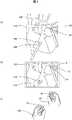
まず、マスタ・スレーブ式マニピュレータシステムの全体に関して、図1を参照しながら説明する。図1は、本発明の一実施形態のマスタ・スレーブ式マニピュレータシステムの全体構成図である。 First, the entire master / slave manipulator system will be described with reference to FIG. FIG. 1 is an overall configuration diagram of a master / slave manipulator system according to an embodiment of the present invention.
患者4は手術台5上に配置されている。手術台5の上方に取り付けられたスレーブマニピュレータ1、2および内視鏡マニピュレータ3は、患者4の患部に向けて配置されている。内視鏡マニピュレータ3は、観察手段である内視鏡を内視鏡視野変更手段であるマニピュレータにより保持する構成となっている。内視鏡マニピュレータ3が保持する内視鏡により撮像された画像は、伝送路19を通ってマスタコンソール7に配置された表示手段であるモニタ6上に表示される。操作者8は、モニタ6を見ながら、マスタコンソール7に取り付けられた操作手段であるマスタデバイス9、10を用いて、モニタ6上に映されているスレーブマニピュレータ1、2の先端部を操作する。 Patient 4 is placed on operating table 5. The
マスタデバイス9、10の動作量は、伝送路20、21を通って操作手段制御部15に送られる。 The operation amounts of the
本システムでは、切替器として、マスタ・スレーブモード切替器12と、内視鏡モード切替器13というオン/オフ式の二つのフットスイッチを備えている。これらのモードの詳細説明については後述する。なお、切替器は二つに分けなくてもよい。 This system includes two on / off foot switches, a master /
マスタ・スレーブモード切替器12のオン/オフ情報は伝送路22を通って切替器制御部14に送られる。マスタ・スレーブモード切替器12がオンの時、切替器制御部14によりマスタ・スレーブモードが選択され、マスタ・スレーブモードオンという情報が切替器制御部14から伝送路24を通して操作手段制御部15に送られる。これによって、マスタデバイス9、10の動作量情報は、操作手段制御部15で適切な座標変換が行われた後、伝送路26を通ってマニピュレータ制御部17に送られる。 On / off information of the master /
マニピュレータ制御部17は、マスタデバイス9、10の動きに応じてスレーブマニピュレータ1、2が動くように逆運動学を解き、算出されたマニピュレータの各関節制御指令を伝送路28、29を通してスレーブマニピュレータ1、2に送り、そのスレーブマニピュレータ1、2の動作を制御する。スレーブマニピュレータ1、2の各関節値は、図示していないエンコーダから取得され、伝送路28、29を通してマニピュレータ制御部17に送られ、制御に用いられる。 The
内視鏡モード切替器13のオン/オフ情報は伝送路23を通して切替器制御部14に送られる。内視鏡モード切替器13がオンの時、切替器制御部14により内視鏡モードが選択され、内視鏡モードオンという情報が切替器制御部14から伝送路24を通して操作手段制御部15に送られる。これによって、マスタデバイス9、10による操作指令値は、伝送路25を通して視野変換部40に送られ、モニタ6上に表示されるスレーブマニピュレータ1、2先端の位置姿勢とマスタデバイス9、10の位置姿勢との関係が一致するように、つまりマスタデバイス9、10による操作方向、スレーブマニピュレータ1、2先端の動作方向が一致するように、内視鏡視野を動かすための指令値を算出し、視野変更制御部18に送る。同時に、マニピュレータ制御部17に対し、内視鏡の姿勢の変化に対応できるように、マニピュレータ先端部姿勢指令値を操作手段制御部15から伝送路35を通してマニピュレータ制御部17に送る。視野変更制御部18では、逆運動学を計算して内視鏡マニピュレータ3の各関節値を計算し、内視鏡マニピュレータ3を動作制御する。 The on / off information of the
図1では、一つの制御装置16の中に、切替器制御部14、操作手段制御部15、視野変更制御部18、マニピュレータ制御部17、視野変換部40が含まれているが、複数の制御装置に分かれていてもよい。なお、視野変換部40が実行する詳細内容については、図3以降を用いて後述する。 In FIG. 1, the switching
次に、図2を参照しながら、マスタコンソール7に関して具体的に説明する。図2は操作者8がマスタコンソール7に取り付けられたマスタデバイス9によりスレーブマニピュレータ1、2、3の操作を行っている本実施形態の様子を示す斜視図である。 Next, the
操作者8は、椅子11に座り、肘置き60に肘あるいは前腕を置き、マスタデバイス9の入力インタフェースである入力装置把持部50を握る。操作者8は、モニタ6を見ながら入力装置把持部50を動かすことにより、モニタ6上に表示されているスレーブマニピュレータ1、2の手先部あるいはモニタ6に画像を送っている内視鏡マニピュレータ3を動かすことができる。なお、モニタ6は、3次元立体表示モニタが好ましいが、2次元表示モニタでもよい。 The
入力装置把持部50は、リンク51、52、ロッド53、ロッド直動軸受け54、ロッド55、図示していないxyテーブル等の移動機構を介してマスタコンソール7に繋がっている。それぞれの部材同士は回転関節あるいは直動関節として繋がっており、図示していないエンコーダやポテンショメータにより各関節値が取得でき、マスタデバイス9の運動学を計算することにより、位置姿勢の6自由度とグリッパ開閉を操作できる。図2では、マスタデバイス9は操作者8の右腕用しか図示されていないが、同様の入力インタフェースは左腕用にもある。マスタコンソール7には、マスタ・スレーブモード切替器12、内視鏡モード切替器13として、それぞれフットスイッチが配置されている。 The input
なお、肘置き60は、マスタコンソール7の中央の柱から伸びて設置されているが、マスタデバイス9の動作範囲とは物理的に干渉しないように配置されている。マスタコンソール7の中央柱と肘置き60をつないでいる部材上には、図示していないがコマンド入力用スイッチが設置されおり、この図2ではフットスイッチとして配置されている切替器のスイッチとしてもよい。また、入力装置把持部50上に配置されている図示していないスイッチを切替用スイッチとしてもよい。 The
図3を参照しながら、入力装置把持部と、モニタと、患部と、マニピュレータの先端部およびグリッパと、内視鏡視野の関係を説明する。図3(a)では、患部100とスレーブマニピュレータ1、2の先端部104、106およびグリッパ102、106と内視鏡視野110との関係を示し、図3(b)では、その時のモニタ6上に表示された患部120とマニピュレータ先端部114、116およびグリッパ112、116との関係を示し、図3(c)では、その時のスレーブマニピュレータ1を操作している入力装置把持部50およびそれを握って操作している操作者の手124と、その時のマニピュレータ2を操作している入力装置把持部70およびそれを握って操作している操作者の手128との関係を示している。 With reference to FIG. 3, the relationship among the input device gripping part, the monitor, the affected part, the tip and gripper of the manipulator, and the endoscope visual field will be described. 3A shows the relationship between the
図3(a)は、マニピュレータ先端部104、106およびグリッパ102、106が患部100に対して設置されている様子である。マニピュレータ先端部104、108にはそれぞれ術具であるグリッパ102、106がついており、マニピュレータ先端部104、108で位置を規定し、グリッパ102、106で姿勢を規定している。患部100を内視鏡マニピュレータ3が撮像しており、わかりやすいように仮想的に内視鏡の視野を110として図示している。 FIG. 3A shows a state where the
図3(b)は、患部100が内視鏡により撮像され、モニタ6上に表示されている様子である。患部100はモニタ6上の患部120として映されている。マニピュレータ先端部104、106およびグリッパ102、106は、モニタ6上のマニピュレータ先端部114、116およびグリッパ112、116として表示される。 FIG. 3B shows a state where the
図3(c)は、操作者の手124、128が入力装置把持部50、70を握っている様子である。入力装置把持部50、70の位置姿勢の関係と、モニタ6上のマニピュレータ先端部114、118およびグリッパ112、116の位置姿勢との関係は、設定したスケール比にしたがって同様に提示され、入力装置把持部50、70の動きと同じように、モニタ6上のマニピュレータ先端部114、118およびグリッパ112、116が動く。 FIG. 3C shows a state where the operator's
図1で示したように、スレーブマニピュレータ1、2および内視鏡マニピュレータ3は、同じ手術台5上に設置されているため、それぞれの座標系および原点を手術台5上のある点に一致させれば、スレーブマニピュレータ1、2および内視鏡マニピュレータ3の先端位置姿勢は、同じ座標系で計算できる。このため、マニピュレータ先端部104、108の位置姿勢の関係と入力装置把持部50、70をあるスケール比にしたがって、同じように配置することが可能である。同様に、入力装置把持部50、70の位置姿勢関係と同じようにモニタ6上のマニピュレータ先端部114、118およびグリッパ112、116が映るように、内視鏡マニピュレータ3の位置姿勢を定めることも可能となる。 As shown in FIG. 1, the
なお、スレーブマニピュレータ1、2および内視鏡マニピュレータ3は、同じ手術台5上に配置する構成により、各座標系を一致させているが、上述した特許3766805号公報で開示されているような方法で、モニタ表示と入力装置把持部の位置姿勢とを一致させてもよい。 The
図3のような状態で、入力装置把持部50の動作限界、あるいは操作者の手124が操作者の体に対して前に出すぎていて腕をこれ以上伸ばせない等の理由から、操作しやすい位置に戻してから操作したいという場合がある。この場合には、マスタとスレーブの間の情報の連結を切って、スレーブを動かさずにマスタを操作しやすい位置に戻して、再び操作を開始したい(クラッチ操作)という要求がある。 In the state as shown in FIG. 3, the operation is performed because of the operation limit of the input
従来技術で、この動作を実行すると、図4のような状態になる。なお、クラッチモードへの切替は、フットスイッチや手元のスイッチなどを用いて行う。図4(a)では、患部100とマニピュレータ先端部104、108およびグリッパ102、106と内視鏡視野110との関係を示し、図4(b)では、その時のモニタ6上に表示された患部120とマニピュレータ先端部114、118およびグリッパ112、116との関係を示し、図4(c)では、その時のスレーブマニピュレータ1、2を操作している入力装置把持部50、150、70、170とそれを握って操作している操作者の手124、224、128、228との関係を示している。 When this operation is executed in the prior art, the state shown in FIG. 4 is obtained. Switching to the clutch mode is performed using a foot switch or a hand switch. 4A shows the relationship between the
従来のクラッチ操作では、図3の状態から、図4(c)に示すように、入力装置把持部50、70およびそれを握っている手124、128の位置から、操作しやすい位置、例えば入力装置把持部150、170およびそれを握っている手224、228の位置にマスタを動かしても、患部100およびマニピュレータ先端部104、108(図4(a))およびそれらがモニタ6上に写る様子(図4(b))は、図3(a)および図3(b)と変わらない。この状態から、切替器を使って再びマスタ・スレーブモードに切り替えたとすると、図4(b)および図4(c)の状態からマスタ・スレーブ動作を動かすことになるが、操作者の手224、228あるいは入力装置把持部150、170の位置姿勢の関係は、モニタ6上に映っているマニピュレータ先端部114、118およびそのグリッパ112、116の位置姿勢の関係と異なっており、操作しづらいという問題がある。 In the conventional clutch operation, from the state of FIG. 3, as shown in FIG. 4 (c), from the position of the input
また、図3の状態から、内視鏡の視野を回転させたいという要望があった場合、従来技術では、例えばヘッドマウントディスプレイに取り付けたジャイロセンサによる回転角に応じて内視鏡視野の回転、あるいはマニピュレータを操作しているマスタデバイス以外の別の内視鏡操作に対応したデバイスで操作、あるいは音声認識による内視鏡の操作、あるいはフットスイッチによる内視鏡操作などによって図5のように内視鏡視野を回転させる。 In addition, when there is a request to rotate the field of view of the endoscope from the state of FIG. 3, in the prior art, for example, rotation of the field of view of the endoscope according to the rotation angle by the gyro sensor attached to the head mounted display, Alternatively, as shown in FIG. 5, the operation can be performed by another device other than the master device that operates the manipulator, or by an endoscope operation by voice recognition or an endoscope operation by a foot switch. Rotate the scope view.
図5(a)では、患部100とマニピュレータ先端部104、108およびグリッパ102、106と内視鏡視野210との関係を示し、図5(b)では、その時のモニタ6上に表示された患部220とマニピュレータ先端部214、218およびグリッパ112、116との関係を示し、図5(c)では、その時のスレーブマニピュレータ1、2を操作している入力装置把持部50、70とそれを握って操作している操作者の手124、128との関係を示している。 5A shows the relationship between the
マスタデバイス9、10の位置姿勢は動かさず、図5(a)の矢印200の向きにマスタデバイス9、10による操作以外の手法で内視鏡視野210を動かすと、視野は内視鏡視野210のように動き、モニタ6上に患部220のように表示され、モニタ6上で、マニピュレータ先端部214、218およびグリッパ212、216のように表示される。この時、モニタ6上に表示されるマニピュレータ先端部214、218およびグリッパ212、216は、図5(C)に示す装置把持部50、70およびそれを握っている手124、128の位置姿勢とは異なっている。このような状態から、マスタ・スレーブを始めると操作の違和感が生じ、操作しづらいという課題がある。 If the endoscope
そこで、本実施形態では、スレーブマニピュレータ1、2を操作するのに用いるマスタデバイス9、10を用いて、内視鏡の視野移動を操作する、あるいは、クラッチ操作に追従した内視鏡視野変更を実現し、マスタ・スレーブモードに復帰した際には、モニタ上に表示されるマニピュレータ先端部の位置姿勢と、入力装置把持部の位置姿勢の関係が対応し、動作方向を一致させることができるようにしてある。以下に、具体的に説明する。 Therefore, in this embodiment, using the
本実施形態による新たなクラッチ操作モードを内視鏡視野追従クラッチモードと呼ぶ。モード切替器12、13によりモードを切り替えるが、本実施形態では、二つのフットスイッチ12、13を切替器として利用し、それぞれの組み合わせでモードを切り替える。モード切替器12、13の組み合わせを図6に示す。 The new clutch operation mode according to the present embodiment is referred to as an endoscope visual field tracking clutch mode. Although the mode is switched by the
図6に示すように、内視鏡モード切替器13をオンの状態にして、マスタ・スレーブモード切替器12をオンにすると、スレーブマニピュレータ1、2の動きに内視鏡視野が追従する内視鏡視野追従マスタ・スレーブモードとなる。内視鏡モード切替器13をオンの状態にして、マスタ・スレーブモード切替器12をオフにすると、内視鏡視野追従クラッチモードとなる。内視鏡モード切替器13をオフの状態にして、マスタ・スレーブモード切替器12をオンにすると、内視鏡視野は変わらず、マスタデバイス9、10の操作に従ってスレーブマニピュレータ1、2が動く通常のマスタ・スレーブ操作となる。内視鏡モード切替器13をオフの状態にして、マスタ・スレーブモード切替器12をオフにすると、全ての接続が切断され、マスタデバイス9、10を動かしても、何も動かないモードとなる。このモードは従来のクラッチモードともいえる。 As shown in FIG. 6, when the
なお、本実施形態では二つのフットスイッチを用いて、モード切替器12、13を実現したが、モードを切り替える手段は、フットスイッチに限らない。 In the present embodiment, the mode switches 12 and 13 are realized using two foot switches. However, the means for switching the modes is not limited to the foot switches.
上述した内視鏡視野追従クラッチモードについて、図7から図10を用いて説明する。 The endoscope visual field tracking clutch mode described above will be described with reference to FIGS.
図3の状態からクラッチ操作によりマスタデバイス9、10を操作しやすい位置に移動する時、操作者はマスタ・スレーブモード切替器12によって内視鏡視野追従クラッチモードを選択する。図7(c)のように、入力装置把持部50、70を手124、128で握っており、そこから入力装置把持部350、370および手324、328の位置に移動したとする。この時、入力装置把持部(350、370)の移動距離、移動姿勢を図示していないエンコーダにより時々刻々計測し、二つの入力装置把持部(350、370)の位置姿勢をそれぞれ算出し、その中点60の移動量と、二つの入力装置把持部(350、370)を結んだ直線が成す角度θを計算する。 When the
図7(c)の場合、入力装置把持部(350、370)の移動が中点60は移動していないため、移動前の入力装置把持部50、70を結んだ仮想的な直線65と移動後の入力装置把持部350、370を結んだ仮想的な直線365との成す角度θ分だけ、図7(a)のように回転の向きを逆にして内視鏡視野310を回転させる。さらに、マニピュレータ先端部104、108は変えずに、モニタ6上で表示されるグリッパ312、316の姿勢が入力装置把持部350、370の姿勢と同じくなるように、グリッパ302、306の姿勢を角度θ分動かす。これにより、図7(b)のモニタ6上に表示されるマニピュレータ先端部314、318およびグリッパ312、316の位置姿勢の関係は、入力装置把持部350、370の位置姿勢の関係と同様になる。 In the case of FIG. 7C, since the movement of the input device gripping part (350, 370) is not moved at the
これにより、クラッチ操作後、すぐにマスタ・スレーブ動作に移行しようとしても、クラッチ操作終了時の手324、328および入力装置把持部350、370の位置姿勢と、モニタ6上に表示されるマニピュレータ先端部314、318及びグリッパ312、316の位置姿勢とが一致しているため、違和感なくマスタ・スレーブ操作が実行できる。 Thereby, even if it is going to shift to the master / slave operation immediately after the clutch operation, the positions and orientations of the
さらに、入力装置把持部450、470が図8(c)の位置に操作者の手424、428によって動かされた時、移動前の入力装置把持部50、70を結んだ仮想的な直線65およびその中点60は、移動後の入力装置把持部450、470を結んだ仮想的な直線465およびその中点460へ動く。この時の動作変位dx(480)、dy(485)を図示していないエンコーダから算出し、この値に対応した移動量kdx(490)、kdy(495)分、図8(a)に示すように、内視鏡視野310から内視鏡視野410へ動かす。これにより、モニタ6上では、図7(b)から図8(b)に示すように内視鏡視野は平行移動し、物理空間上の入力装置把持部450、470に対応した位置姿勢に、マニピュレータ先端部414、418およびグリッパ412、416が表示される。なお、入力装置把持部中点の移動量と、内視鏡視野の移動量のスケール比kは、対象患部やシチュエーションにより変更可能である。 Further, when the input
これらより、クラッチ操作時の入力装置把持部の動きが、回転および平行移動を伴っていても、クラッチ操作後マスタ・スレーブ動作に移行する際、クラッチ操作終了時の手424、428および入力装置把持部450、470の位置姿勢と、モニタ6上に表示されるマニピュレータ先端部414、418及びグリッパ412、416の位置姿勢が一致し、操作方向と動作方向が一致するため、違和感なくマスタ・スレーブ操作が実行できる。 As a result, even when the movement of the input device gripping part during clutch operation involves rotation and parallel movement, when shifting to the master / slave operation after the clutch operation, the
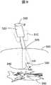
図9、図10に入力装置把持部を動かした際の内視鏡あるいは、カメラの動きについて述べる。対象観察手段が内視鏡で、内視鏡下手術を対象とした場合、図9に示すように、内視鏡の軸は体表500により拘束され、体表刺入点505を中心にしたピボット運動と軸回転しか内視鏡は動かせない。 9 and 10 describe the movement of the endoscope or the camera when the input device gripping part is moved. When the object observation means is an endoscope and an endoscopic operation is the object, the axis of the endoscope is constrained by the
そのため、図8(a)で説明したような内視鏡視野310、410の動きは、図9に示すような内視鏡510、520の動きによって視野変更される。図3の視野状態を実現する内視鏡の位置を510とすると、図8(c)の入力装置把持部の変位dx(480)、dy(485)に伴い、設定されたスケール比と内視鏡のズーム比から計算される係数sを掛けたsdx(540)、sdy(550)の動作量で520の位置に内視鏡を動かし、患部590を撮像する。また、図7で示した視野の回転θは、図9の矢印530で示されるように内視鏡軸を回転させて実現する。 Therefore, the movement of the endoscope
内視鏡手術以外の場合、例えば胸にある程度の大きさの穴を開けて行う手術や、手術に限らず、カメラ視野の動きが限定されないマスタ・スレーブ作業の場合は、双腕の入力装置把持部の中点の移動量dx(650)、dy(655)、dz(660)に応じてカメラ視野を平行移動し、双腕の入力装置把持部を結んだ線の姿勢の変位をロール、ピッチ、ヨーで計算し、その角度偏差にあわせて、カメラ軸を移動することにより視野を変更することも可能である。その場合の実施形態の一つを図10に示し、以下に説明する。 In cases other than endoscopic surgery, for example, surgery performed with a hole of a certain size in the chest, or master / slave work that does not limit movement of the camera field of view, not limited to surgery, grasping a dual-arm input device The camera's field of view is translated according to the amount of movement dx (650), dy (655), dz (660) of the middle point of the unit, and the displacement of the posture of the line connecting the two-arm input device gripping unit is set to roll, pitch It is also possible to change the field of view by calculating with yaw and moving the camera axis in accordance with the angular deviation. One embodiment in that case is shown in FIG. 10 and will be described below.
内視鏡視野追従クラッチモードを選択し、入力装置把持部の中点680が、新たな中点690に移動した際の変位が、物理座標系680上で、dx(650)、dy(655)、dz(660)として算出されるとする。また、この時の入力装置把持部を結ぶ直線の姿勢変化のロール、ピッチ、ヨー(α、β、γ)(670)を算出する。ただし、直線の軸回転の姿勢は、入力装置把持部を結んだ直線というだけでは定まらないので、固定としてもよい。この情報に基づき、対象600を撮像するカメラを、モーションスケール比kに従ってkdx(625)、kdy(630)、kdz(635)動かし、さらに、姿勢変化分のロールピッチヨー(α、β、γ)(640)動かすことにより、内視鏡を610から620に動かす。これにより、モニタ6上では、操作入力装置の平行移動量と内視鏡視野の回転(ヨー回転)だけでなく、ロールピッチにも対応した内視鏡視野を提供でき、把持入力装置の操作方向とモニタ上のマニピュレータの動作方向の一致性が高まる。 When the endoscope visual field tracking clutch mode is selected and the
次に、内視鏡視野の変更を行ってもマスタとモニタ上のスレーブの位置姿勢関係が保たれ、内視鏡視野からマニピュレータ先端部が外れない本実施形態の手法について、図11、12を用いて説明する。この手法は、図6で説明した内視鏡視野追従マスタ・スレーブモードを選択した際に起動される。 Next, with respect to the method of this embodiment, the position and orientation relationship between the master and the slave on the monitor is maintained even if the endoscope field of view is changed, and the tip of the manipulator is not detached from the endoscope field of view. It explains using. This method is activated when the endoscope visual field tracking master / slave mode described with reference to FIG. 6 is selected.
内視鏡視野追従マスタ・スレーブモードは、マスタ・スレーブの接続を保ったまま、内視鏡の視野も変更するというものである。 The endoscope visual field tracking master / slave mode changes the visual field of the endoscope while keeping the master / slave connection.
通常は、図5で説明したように、モニタ6上のスレーブマニピュレータの位置姿勢と、入力装置把持部の位置姿勢の関係がずれてしまい、動作方向と操作方向が一致しなくなる。内視鏡視野の回転については、内視鏡視野追従クラッチモードと同じ手法を用いて図7で説明したように、モニタ上に表示されるマニピュレータ位置姿勢と、マスタの入力装置把持部の位置姿勢の対応を一致させる。 Normally, as described with reference to FIG. 5, the relationship between the position and orientation of the slave manipulator on the
図11を用いて、内視鏡視野の平行移動について、内視鏡が体表に拘束され、平面2自由度方向および直動あるいはズーム機能と、内視鏡軸回転しかできない場合について説明する。図11(a)は、患部700を内視鏡視野720(わかりやすいように仮想的に表示)により撮像している様子である。図11(b)は、その時の入力装置把持部の様子である。 With reference to FIG. 11, a description will be given of a case where the endoscope is constrained by the body surface and the direction of two degrees of freedom in the plane and the linear movement or zoom function and the rotation of the endoscope axis can be performed. FIG. 11A shows a state where the
内視鏡視野追従マスタ・スレーブモードにおいては、内視鏡視野平面(仮に座標系をOs(790)とする)と対応した物理空間平面(座標系をOm(780)とする)においての双腕の入力装置把持部765、775の移動偏差ベクトルVr(760)、Vl(770)を計算する。この移動偏差ベクトルVr(760)、Vl(770)にモーションスケール比kをかけたkVr(710)、kVl(735)ベクトル分、スレーブマニピュレータ先端は705から715へ、および730から740へ移動する。この時、内視鏡視野720は、ベクトルk(Vr+Vl)/2 (745)分、移動して、内視鏡視野725となることにより、マニピュレータ先端部の移動を追従する。 In the endoscope visual field tracking master / slave mode, the dual arm on the physical space plane (the coordinate system is Om (780)) corresponding to the endoscope visual field plane (the coordinate system is assumed to be Os (790)). The movement deviation vectors Vr (760) and Vl (770) of the input device grips 765 and 775 are calculated. The tip of the slave manipulator moves from 705 to 715 and from 730 to 740 by kVr (710) and kVl (735) vectors obtained by multiplying the movement deviation vectors Vr (760) and Vl (770) by the motion scale ratio k. At this time, the endoscope
しかし、図12(c)に示すようにベクトルVr(875)とVl(890)の向きが逆方向を向いている場合、内視鏡視野は動かず、画面から外れる方向に、マニピュレータ先端部が動く可能性も考えられる。そこで、図12(c)に示すように、二つの入力装置把持部880、885の距離m(895)を計算し、この距離の差分Δmの正負によって、ズームイン・ズームアウトあるいは、内視鏡軸直動で対象に近づく・内視鏡軸直動で対象から遠ざかるという動作を行う。 However, when the vectors Vr (875) and Vl (890) are directed in opposite directions as shown in FIG. 12 (c), the endoscope field of view does not move and the manipulator tip portion moves away from the screen. There is a possibility of movement. Therefore, as shown in FIG. 12 (c), the distance m (895) between the two input
図12(a)は、図12(c)の状態で入力装置把持部880、885が保持されているときに、患部800とスレーブマニピュレータ815、820がモニタ810に表示されている様子である。図12(b)は、図12(a)の状態のときのマニピュレータ先端部845、860が、内視鏡視野追従モードの使用により、マニピュレータ先端が850および865の方向に移動し、内視鏡画像がズームアウトしたときの患部830およびマニピュレータ855、870のモニタ840に表示された様子である。 FIG. 12A shows a state where the
距離の差分Δmが正、つまり二つの入力装置把持部の距離m(895)が大きくなる場合、二つの入力装置把持部の動きにより、マニピュレータ先端部も845から855、860から870へと遠ざかる動きとなり、内視鏡視野つまり、モニタ画面内からはずれる方向に動くことになる。そのため、内視鏡追従マスタ・スレーブモードでは、Δmが大きくなるにしたがって、ズームアウトあるいは内視鏡軸直動で対象から遠ざかるという動きを行う。これにより、常にモニタ840上にマニピュレータ先端部が表示されるように内視鏡視野を動かすことができる。 When the distance difference Δm is positive, that is, when the distance m (895) between the two input device gripping portions becomes large, the manipulator tip moves away from 845 to 855 and from 860 to 870 due to the movement of the two input device gripping portions. Thus, the endoscope moves in a direction deviating from the endoscope visual field, that is, the monitor screen. For this reason, in the endoscope follow-up master / slave mode, as Δm increases, movement away from the target is performed by zooming out or linearly moving the endoscope axis. Thereby, the endoscope visual field can be moved so that the tip of the manipulator is always displayed on the
距離の差分Δmが負、つまり二つの入力装置把持部の距離m(895)が小さくなる場合、二つの入力装置把持部の動きにより、マニピュレータ先端部は接近する方向となる。この場合は、Δmの値に従って内視鏡をズームインあるいは内視鏡軸直動を対象に近づける動きを行う。マニピュレータ先端部同士が近づいている部分とは、注視したい対象であり、ズームインして、詳細が見たいという人間の直感にも対応した動きとなる。なお、Δmに対応するズーム比率は、適宜設定可能とする。 When the distance difference Δm is negative, that is, when the distance m (895) between the two input device gripping portions is small, the tip of the manipulator approaches the direction by the movement of the two input device gripping portions. In this case, in accordance with the value of Δm, the endoscope is zoomed in or moved in such a manner that the endoscope axis linear movement approaches the target. The portion where the manipulator tips are close to each other is an object to be watched, and the movement corresponds to the human intuition that the user wants to zoom in and see details. Note that the zoom ratio corresponding to Δm can be set as appropriate.
上記、内視鏡視野の変換を図1で示した視野変換部40で行うことにより、内視鏡視野追従マスタ・スレーブモードでは、マスタとスレーブの通信は接続しながらも、マニピュレータ先端部がモニタ6上からはずれないように、内視鏡視野を動かすことが可能となる。これにより、内視鏡視野の変更あるいは、クラッチ操作を行って、マスタ・スレーブモードに戻った時でも、マスタとモニタ上のスレーブの位置姿勢関係が常に保たれ、操作性のよい直感的なマスタ・スレーブ操作が実現できる。 In the endoscope visual field tracking master / slave mode, the distal end of the manipulator is monitored while the communication between the master and the slave is connected by performing the visual
上述した本実施形態によれば、モード切替器により選択したクラッチモード時に、操作手段の変位量を計測し、その変位量に対応して、内視鏡視野を動かすことにより、クラッチモード中は、マニピュレータの位置は動かず、モニタ上に表示される内視鏡画像中のマニピュレータの位置関係と、操作手段の入力装置把持部の位置関係とが同じ位置関係になるように、内視鏡視野を動かす。さらにマニピュレータ先端部についたグリッパ姿勢を、入力装置把持部の姿勢と同じくするように、マニピュレータのグリッパを動かし、モニタに表示されるグリッパ姿勢と入力装置把持部姿勢とを同じにすることにより、常に、入力装置把持部の位置姿勢とモニタ上に表示されるマニピュレータの位置姿勢とを保つことにより、クラッチモードからマスタ・スレーブモードに移行しても、動作方向が一致しているため常に直感的な操作を提供できる。 According to the above-described embodiment, during the clutch mode selected by the mode switch, the amount of displacement of the operating means is measured, and the endoscope visual field is moved in accordance with the amount of displacement. The position of the manipulator does not move, and the endoscope visual field is adjusted so that the positional relationship of the manipulator in the endoscopic image displayed on the monitor and the positional relationship of the input device gripping part of the operation means are the same positional relationship. move. Furthermore, by moving the gripper of the manipulator so that the gripper posture attached to the tip of the manipulator is the same as the posture of the input device gripper, the gripper posture displayed on the monitor and the input device gripper posture are always the same. By maintaining the position and orientation of the gripping part of the input device and the position and orientation of the manipulator displayed on the monitor, it is always intuitive because the operation direction is the same even when shifting from the clutch mode to the master / slave mode. Can provide operation.
即ち、カメラ視野を変更しても、クラッチ操作によりマスタの位置姿勢を変更しても、表示手段上に写されるスレーブマニピュレータ作業部の位置姿勢と、操作手段の位置姿勢が対応し、マスタ・スレーブモードに移行後すぐに、動作方向を一致して動かすことが可能な手段を提供することにより、操作者に良好な視野を提供することができる。良好な視野を提供することにより、マニピュレータシステムの操作性が向上し、マニピュレータシステム操作の安全性が向上できる。また、表示手段上のマニピュレータ位置姿勢と操作手段の位置姿勢を一致させるための手間が省かれ、マニピュレータシステムの操作時間が短縮され、作業効率が向上できる。また、操作手段にアクチュエータを配置し、表示手段上のマニピュレータ位置姿勢と対応がとれるように、操作手段に力を与えて位置姿勢を変更するといった必要もなくなり、操作手段装置の小型化が図れる。また、そのためのアクチュエータを必要としないため、価格も安く、予期しないエラーの際にも操作者に害が及ぼされる心配がなく安全である。 That is, even if the camera field of view is changed or the position and orientation of the master is changed by clutch operation, the position and orientation of the slave manipulator working unit imaged on the display means correspond to the position and orientation of the operating means. By providing a means capable of moving the movement direction in accordance with the movement mode immediately after shifting to the slave mode, a good visual field can be provided to the operator. By providing a good visual field, the operability of the manipulator system is improved, and the safety of manipulator system operation can be improved. Further, the labor for matching the manipulator position / posture on the display means and the position / posture of the operation means is eliminated, the operation time of the manipulator system is shortened, and the work efficiency can be improved. Further, it is not necessary to change the position and orientation by applying a force to the operation means so that an actuator is arranged in the operation means and the manipulator position and orientation on the display means can be taken, and the operation means device can be downsized. In addition, since an actuator for this purpose is not required, the price is low, and there is no concern that the operator will be harmed in the event of an unexpected error, and it is safe.
なお、従来の技術では、内視鏡視野を動かしている間は、対象に対して仕事を行うマニピュレータは仕事を行うことができず、止まっていたため、作業時間が長くなるという課題があった。しかし、本実施形態を用いることにより、内視鏡視野の移動と共にマニピュレータも動かすことができるため、作業効率が向上し、作業時間も短縮される。また、従来のクラッチモードも切替器により選択できるようにすることにより、内視鏡視野を動かさずにクラッチ操作を行うことも可能で、状況に応じた操作者の使い分けが可能で、操作性を悪化させることはない。 In the prior art, the manipulator that performs work on the target cannot work while moving the endoscope visual field, and has stopped, so there is a problem that the work time becomes long. However, by using this embodiment, the manipulator can be moved along with the movement of the endoscope visual field, so that the working efficiency is improved and the working time is shortened. In addition, by enabling the selection of the conventional clutch mode using the switch, it is possible to operate the clutch without moving the endoscope field of view. There is no deterioration.
1、2…マニピュレータ、3…内視鏡マニピュレータ、4…患者、5…手術台、6…モニタ(表示手段)、7…マスタコンソール、8…操作者、9、10…マスタデバイス(操作手段)、11…椅子、12…マスタ・スレーブモード切替器、13…内視鏡モード切替器、14…切替器制御部、15…操作手段制御部、16…制御装置、17…マニピュレータ制御部、18…視野変更制御部、40…視野変換部、50…入力装置把持部。 DESCRIPTION OF
Claims (4)
Translated fromJapaneseその操作指令を読み取り第1の制御指令を送る操作手段制御部と、
前記第1の制御指令に基づきスレーブマニピュレータの各関節を制御するための第2の制御指令を出力するマニピュレータ制御部と、
前記第2の制御指令に基づいて動作する前記スレーブマニピュレータと、
前記スレーブマニピュレータの動作を観察する観察手段と、
前記観察手段の視野を変更する視野変更手段と、
前記視野変更手段を制御する視野変更制御部と、
前記観察手段で観察したマニピュレータの映像を画面に表示する表示手段とを備えたマニピュレータシステムにおいて、
前記スレーブマニピュレータを制御するマスタ・スレーブモードと、前記操作手段から前記スレーブマニピュレータへの操作指令の伝達を切断して前記操作手段を任意の位置姿勢に移動する観察手段視野追従クラッチモードとを切り替えるモード切替手段と、
前記モード切替手段の信号を読み取り前記操作手段制御部にモード信号を送る切替器制御部と、
前記操作手段制御部で読み取った観察手段視野追従クラッチモード時の操作指令に基づき、前記表示手段に表示されるスレーブマニピュレータの映像の動作方向と前記操作手段の操作方向とを一致させるように、前記マニピュレータ制御部に第3の制御指令を送ると共に前記視野変更制御部に第4の制御指令を送る視野変換部とを備えた
ことを特徴とするマスタ・スレーブ式マニピュレータシステム。An operating means for operating to generate an operation command;
An operation means controller that reads the operation command and sends a first control command;
A manipulator control unit that outputs a second control command for controlling each joint of the slave manipulator based on the first control command;
The slave manipulator operating based on the second control command;
Observation means for observing the operation of the slave manipulator;
Visual field changing means for changing the visual field of the observation means;
A visual field change control unit for controlling the visual field change means;
In a manipulator system comprising display means for displaying a video of the manipulator observed by the observation means on a screen,
A mode for switching between a master / slave mode for controlling the slave manipulator and an observation means visual field follow-up clutch mode for cutting the transmission of an operation command from the operation means to the slave manipulator and moving the operation means to an arbitrary position and orientation. Switching means;
A switch control unit that reads a signal of the mode switching unit and sends a mode signal to the operation unit control unit;
Based on the operation command in the observation means visual field tracking clutch mode read by the operation means control unit, the operation direction of the image of the slave manipulator displayed on the display means is matched with the operation direction of the operation means. A master / slave manipulator system comprising: a visual field conversion unit that transmits a third control command to the manipulator control unit and transmits a fourth control command to the visual field change control unit.
その操作指令を読み取り第1の制御指令を送る操作手段制御部と、An operation means controller that reads the operation command and sends a first control command;
前記第1の制御指令に基づきスレーブマニピュレータの各関節を制御するための第2の制御指令を出力するマニピュレータ制御部と、A manipulator control unit that outputs a second control command for controlling each joint of the slave manipulator based on the first control command;
前記第2の制御指令に基づいて動作する前記スレーブマニピュレータと、The slave manipulator operating based on the second control command;
前記スレーブマニピュレータの動作を観察する観察手段と、Observation means for observing the operation of the slave manipulator;
前記観察手段の視野を変更する視野変更手段と、Visual field changing means for changing the visual field of the observation means;
前記視野変更手段を制御する視野変更制御部と、A visual field change control unit for controlling the visual field change means;
前記観察手段で観察したマニピュレータの映像を画面に表示する表示手段とを備えたマニピュレータシステムにおいて、In a manipulator system comprising display means for displaying a video of the manipulator observed by the observation means on a screen,
前記スレーブマニピュレータを制御するマスタ・スレーブモードと、前記操作手段から前記スレーブマニピュレータへの操作指令の伝達を切断して前記操作手段を任意の位置姿勢に移動する観察手段視野追従クラッチモードと、前記操作手段によって操作する対象をスレーブマニピュレータ及び観察手段視野とする観察手段視野追従マスタ・スレーブモードとを切り替えるモード切替手段と、Master-slave mode for controlling the slave manipulator, observation means visual field tracking clutch mode for cutting the transmission of an operation command from the operation means to the slave manipulator and moving the operation means to an arbitrary position and posture, and the operation Mode switching means for switching between the observation unit visual field tracking master / slave mode with the slave manipulator and the observation means visual field to be operated by the means;
前記モード切替手段の信号を読み取り前記操作手段制御部にモード信号を送る切替器制御部と、A switch control unit that reads a signal of the mode switching unit and sends a mode signal to the operation unit control unit;
前記操作手段制御部で読み取った観察手段視野追従クラッチモード時の操作指令に基づき、前記表示手段に表示されるスレーブマニピュレータの映像の動作方向と前記操作手段の操作方向とを一致させるように、前記マニピュレータ制御部に第3の制御指令を送ると共に前記視野変更制御部に第4の制御指令を送る視野変換部とを備えたBased on the operation command in the observation means visual field tracking clutch mode read by the operation means control unit, the operation direction of the image of the slave manipulator displayed on the display means is matched with the operation direction of the operation means. And a visual field conversion unit that sends a third control command to the manipulator control unit and sends a fourth control command to the visual field change control unit.
ことを特徴とするマスタ・スレーブ式マニピュレータシステム。A master-slave manipulator system characterized by this.
Priority Applications (3)
| Application Number | Priority Date | Filing Date | Title |
|---|---|---|---|
| JP2007072447AJP4916011B2 (en) | 2007-03-20 | 2007-03-20 | Master / slave manipulator system |
| EP08001129AEP1973021B1 (en) | 2007-03-20 | 2008-01-22 | Master-slave manipulator system |
| US12/019,668US8002694B2 (en) | 2007-03-20 | 2008-01-25 | Master-slave manipulator system |
Applications Claiming Priority (1)
| Application Number | Priority Date | Filing Date | Title |
|---|---|---|---|
| JP2007072447AJP4916011B2 (en) | 2007-03-20 | 2007-03-20 | Master / slave manipulator system |
Publications (2)
| Publication Number | Publication Date |
|---|---|
| JP2008228967A JP2008228967A (en) | 2008-10-02 |
| JP4916011B2true JP4916011B2 (en) | 2012-04-11 |
Family
ID=39592756
Family Applications (1)
| Application Number | Title | Priority Date | Filing Date |
|---|---|---|---|
| JP2007072447AExpired - Fee RelatedJP4916011B2 (en) | 2007-03-20 | 2007-03-20 | Master / slave manipulator system |
Country Status (3)
| Country | Link |
|---|---|
| US (1) | US8002694B2 (en) |
| EP (1) | EP1973021B1 (en) |
| JP (1) | JP4916011B2 (en) |
Cited By (2)
| Publication number | Priority date | Publication date | Assignee | Title |
|---|---|---|---|---|
| JPWO2023127026A1 (en)* | 2021-12-27 | 2023-07-06 | ||
| WO2023127024A1 (en)* | 2021-12-27 | 2023-07-06 | リバーフィールド株式会社 | Surgery assisting device |
Families Citing this family (355)
| Publication number | Priority date | Publication date | Assignee | Title |
|---|---|---|---|---|
| US20070084897A1 (en) | 2003-05-20 | 2007-04-19 | Shelton Frederick E Iv | Articulating surgical stapling instrument incorporating a two-piece e-beam firing mechanism |
| US9060770B2 (en) | 2003-05-20 | 2015-06-23 | Ethicon Endo-Surgery, Inc. | Robotically-driven surgical instrument with E-beam driver |
| US11890012B2 (en) | 2004-07-28 | 2024-02-06 | Cilag Gmbh International | Staple cartridge comprising cartridge body and attached support |
| US9072535B2 (en) | 2011-05-27 | 2015-07-07 | Ethicon Endo-Surgery, Inc. | Surgical stapling instruments with rotatable staple deployment arrangements |
| US9943372B2 (en) | 2005-04-18 | 2018-04-17 | M.S.T. Medical Surgery Technologies Ltd. | Device having a wearable interface for improving laparoscopic surgery and methods for use thereof |
| US9492240B2 (en)* | 2009-06-16 | 2016-11-15 | Intuitive Surgical Operations, Inc. | Virtual measurement tool for minimally invasive surgery |
| US7669746B2 (en) | 2005-08-31 | 2010-03-02 | Ethicon Endo-Surgery, Inc. | Staple cartridges for forming staples having differing formed staple heights |
| US10159482B2 (en) | 2005-08-31 | 2018-12-25 | Ethicon Llc | Fastener cartridge assembly comprising a fixed anvil and different staple heights |
| US11246590B2 (en) | 2005-08-31 | 2022-02-15 | Cilag Gmbh International | Staple cartridge including staple drivers having different unfired heights |
| US11484312B2 (en) | 2005-08-31 | 2022-11-01 | Cilag Gmbh International | Staple cartridge comprising a staple driver arrangement |
| US7934630B2 (en) | 2005-08-31 | 2011-05-03 | Ethicon Endo-Surgery, Inc. | Staple cartridges for forming staples having differing formed staple heights |
| US20070106317A1 (en) | 2005-11-09 | 2007-05-10 | Shelton Frederick E Iv | Hydraulically and electrically actuated articulation joints for surgical instruments |
| US7753904B2 (en) | 2006-01-31 | 2010-07-13 | Ethicon Endo-Surgery, Inc. | Endoscopic surgical instrument with a handle that can articulate with respect to the shaft |
| US20120292367A1 (en) | 2006-01-31 | 2012-11-22 | Ethicon Endo-Surgery, Inc. | Robotically-controlled end effector |
| US7845537B2 (en) | 2006-01-31 | 2010-12-07 | Ethicon Endo-Surgery, Inc. | Surgical instrument having recording capabilities |
| US8186555B2 (en) | 2006-01-31 | 2012-05-29 | Ethicon Endo-Surgery, Inc. | Motor-driven surgical cutting and fastening instrument with mechanical closure system |
| US8820603B2 (en) | 2006-01-31 | 2014-09-02 | Ethicon Endo-Surgery, Inc. | Accessing data stored in a memory of a surgical instrument |
| US11793518B2 (en) | 2006-01-31 | 2023-10-24 | Cilag Gmbh International | Powered surgical instruments with firing system lockout arrangements |
| US8708213B2 (en) | 2006-01-31 | 2014-04-29 | Ethicon Endo-Surgery, Inc. | Surgical instrument having a feedback system |
| US20110295295A1 (en) | 2006-01-31 | 2011-12-01 | Ethicon Endo-Surgery, Inc. | Robotically-controlled surgical instrument having recording capabilities |
| US8992422B2 (en) | 2006-03-23 | 2015-03-31 | Ethicon Endo-Surgery, Inc. | Robotically-controlled endoscopic accessory channel |
| US10568652B2 (en) | 2006-09-29 | 2020-02-25 | Ethicon Llc | Surgical staples having attached drivers of different heights and stapling instruments for deploying the same |
| US11980366B2 (en) | 2006-10-03 | 2024-05-14 | Cilag Gmbh International | Surgical instrument |
| US8684253B2 (en) | 2007-01-10 | 2014-04-01 | Ethicon Endo-Surgery, Inc. | Surgical instrument with wireless communication between a control unit of a robotic system and remote sensor |
| US11291441B2 (en) | 2007-01-10 | 2022-04-05 | Cilag Gmbh International | Surgical instrument with wireless communication between control unit and remote sensor |
| US8632535B2 (en) | 2007-01-10 | 2014-01-21 | Ethicon Endo-Surgery, Inc. | Interlock and surgical instrument including same |
| US20080169333A1 (en) | 2007-01-11 | 2008-07-17 | Shelton Frederick E | Surgical stapler end effector with tapered distal end |
| US7673782B2 (en) | 2007-03-15 | 2010-03-09 | Ethicon Endo-Surgery, Inc. | Surgical stapling instrument having a releasable buttress material |
| US8931682B2 (en) | 2007-06-04 | 2015-01-13 | Ethicon Endo-Surgery, Inc. | Robotically-controlled shaft based rotary drive systems for surgical instruments |
| US11564682B2 (en) | 2007-06-04 | 2023-01-31 | Cilag Gmbh International | Surgical stapler device |
| US7753245B2 (en) | 2007-06-22 | 2010-07-13 | Ethicon Endo-Surgery, Inc. | Surgical stapling instruments |
| US11849941B2 (en) | 2007-06-29 | 2023-12-26 | Cilag Gmbh International | Staple cartridge having staple cavities extending at a transverse angle relative to a longitudinal cartridge axis |
| US8636736B2 (en) | 2008-02-14 | 2014-01-28 | Ethicon Endo-Surgery, Inc. | Motorized surgical cutting and fastening instrument |
| US8573465B2 (en) | 2008-02-14 | 2013-11-05 | Ethicon Endo-Surgery, Inc. | Robotically-controlled surgical end effector system with rotary actuated closure systems |
| US7819298B2 (en) | 2008-02-14 | 2010-10-26 | Ethicon Endo-Surgery, Inc. | Surgical stapling apparatus with control features operable with one hand |
| US11986183B2 (en) | 2008-02-14 | 2024-05-21 | Cilag Gmbh International | Surgical cutting and fastening instrument comprising a plurality of sensors to measure an electrical parameter |
| JP5410110B2 (en) | 2008-02-14 | 2014-02-05 | エシコン・エンド−サージェリィ・インコーポレイテッド | Surgical cutting / fixing instrument with RF electrode |
| US9179912B2 (en) | 2008-02-14 | 2015-11-10 | Ethicon Endo-Surgery, Inc. | Robotically-controlled motorized surgical cutting and fastening instrument |
| US7866527B2 (en) | 2008-02-14 | 2011-01-11 | Ethicon Endo-Surgery, Inc. | Surgical stapling apparatus with interlockable firing system |
| US9585657B2 (en) | 2008-02-15 | 2017-03-07 | Ethicon Endo-Surgery, Llc | Actuator for releasing a layer of material from a surgical end effector |
| US8155479B2 (en) | 2008-03-28 | 2012-04-10 | Intuitive Surgical Operations Inc. | Automated panning and digital zooming for robotic surgical systems |
| US8808164B2 (en) | 2008-03-28 | 2014-08-19 | Intuitive Surgical Operations, Inc. | Controlling a robotic surgical tool with a display monitor |
| US11648005B2 (en) | 2008-09-23 | 2023-05-16 | Cilag Gmbh International | Robotically-controlled motorized surgical instrument with an end effector |
| US9386983B2 (en) | 2008-09-23 | 2016-07-12 | Ethicon Endo-Surgery, Llc | Robotically-controlled motorized surgical instrument |
| US8210411B2 (en) | 2008-09-23 | 2012-07-03 | Ethicon Endo-Surgery, Inc. | Motor-driven surgical cutting instrument |
| US9005230B2 (en) | 2008-09-23 | 2015-04-14 | Ethicon Endo-Surgery, Inc. | Motorized surgical instrument |
| US8608045B2 (en) | 2008-10-10 | 2013-12-17 | Ethicon Endo-Sugery, Inc. | Powered surgical cutting and stapling apparatus with manually retractable firing system |
| KR101038417B1 (en)* | 2009-02-11 | 2011-06-01 | 주식회사 이턴 | Surgical Robot System and Its Control Method |
| US9155592B2 (en) | 2009-06-16 | 2015-10-13 | Intuitive Surgical Operations, Inc. | Virtual measurement tool for minimally invasive surgery |
| FR2950559B1 (en)* | 2009-09-29 | 2011-11-25 | Artistic Robot Event | SYSTEM AND METHOD FOR SYNCHRONOUS RESTITUTION BY A ROBOT OF MOVEMENTS OF A HAND OR END BODY |
| US8220688B2 (en) | 2009-12-24 | 2012-07-17 | Ethicon Endo-Surgery, Inc. | Motor-driven surgical cutting instrument with electric actuator directional control assembly |
| JP5530234B2 (en)* | 2010-03-29 | 2014-06-25 | オリンパス株式会社 | Operation input device and manipulator system |
| US11298125B2 (en) | 2010-09-30 | 2022-04-12 | Cilag Gmbh International | Tissue stapler having a thickness compensator |
| US9016542B2 (en) | 2010-09-30 | 2015-04-28 | Ethicon Endo-Surgery, Inc. | Staple cartridge comprising compressible distortion resistant components |
| US9351730B2 (en) | 2011-04-29 | 2016-05-31 | Ethicon Endo-Surgery, Llc | Tissue thickness compensator comprising channels |
| US11925354B2 (en) | 2010-09-30 | 2024-03-12 | Cilag Gmbh International | Staple cartridge comprising staples positioned within a compressible portion thereof |
| US9629814B2 (en) | 2010-09-30 | 2017-04-25 | Ethicon Endo-Surgery, Llc | Tissue thickness compensator configured to redistribute compressive forces |
| US9788834B2 (en) | 2010-09-30 | 2017-10-17 | Ethicon Llc | Layer comprising deployable attachment members |
| US9386988B2 (en) | 2010-09-30 | 2016-07-12 | Ethicon End-Surgery, LLC | Retainer assembly including a tissue thickness compensator |
| US11812965B2 (en) | 2010-09-30 | 2023-11-14 | Cilag Gmbh International | Layer of material for a surgical end effector |
| US10945731B2 (en) | 2010-09-30 | 2021-03-16 | Ethicon Llc | Tissue thickness compensator comprising controlled release and expansion |
| US12213666B2 (en) | 2010-09-30 | 2025-02-04 | Cilag Gmbh International | Tissue thickness compensator comprising layers |
| US8695866B2 (en) | 2010-10-01 | 2014-04-15 | Ethicon Endo-Surgery, Inc. | Surgical instrument having a power control circuit |
| WO2012073789A1 (en)* | 2010-11-30 | 2012-06-07 | オリンパス株式会社 | Master control input device and master-slave manipulator |
| KR102143818B1 (en)* | 2011-02-15 | 2020-08-13 | 인튜어티브 서지컬 오퍼레이션즈 인코포레이티드 | Indicator for knife location in a stapling or vessel sealing instrument |
| JP2012171088A (en)* | 2011-02-24 | 2012-09-10 | Olympus Corp | Master operation input device, and master-slave manipulator |
| EP2688717B1 (en)* | 2011-03-23 | 2023-10-18 | SRI International | Dexterous telemanipulator system |
| US8860726B2 (en)* | 2011-04-12 | 2014-10-14 | Autodesk, Inc. | Transform manipulator control |
| AU2012250197B2 (en) | 2011-04-29 | 2017-08-10 | Ethicon Endo-Surgery, Inc. | Staple cartridge comprising staples positioned within a compressible portion thereof |
| US11207064B2 (en) | 2011-05-27 | 2021-12-28 | Cilag Gmbh International | Automated end effector component reloading system for use with a robotic system |
| JP5784388B2 (en)* | 2011-06-29 | 2015-09-24 | オリンパス株式会社 | Medical manipulator system |
| CN103607971B (en)* | 2011-07-07 | 2016-08-31 | 奥林巴斯株式会社 | Medical master-slave operator |
| JP5800610B2 (en)* | 2011-07-07 | 2015-10-28 | オリンパス株式会社 | Medical master-slave manipulator |
| JP5800609B2 (en)* | 2011-07-07 | 2015-10-28 | オリンパス株式会社 | Medical master-slave manipulator |
| JP6009840B2 (en) | 2011-08-04 | 2016-10-19 | オリンパス株式会社 | Medical equipment |
| JP6021353B2 (en)* | 2011-08-04 | 2016-11-09 | オリンパス株式会社 | Surgery support device |
| JP5841451B2 (en) | 2011-08-04 | 2016-01-13 | オリンパス株式会社 | Surgical instrument and control method thereof |
| JP6021484B2 (en) | 2011-08-04 | 2016-11-09 | オリンパス株式会社 | Medical manipulator |
| JP5953058B2 (en) | 2011-08-04 | 2016-07-13 | オリンパス株式会社 | Surgery support device and method for attaching and detaching the same |
| JP6081061B2 (en) | 2011-08-04 | 2017-02-15 | オリンパス株式会社 | Surgery support device |
| JP6000641B2 (en) | 2011-08-04 | 2016-10-05 | オリンパス株式会社 | Manipulator system |
| JP5931497B2 (en) | 2011-08-04 | 2016-06-08 | オリンパス株式会社 | Surgery support apparatus and assembly method thereof |
| JP5936914B2 (en) | 2011-08-04 | 2016-06-22 | オリンパス株式会社 | Operation input device and manipulator system including the same |
| WO2013018861A1 (en)* | 2011-08-04 | 2013-02-07 | オリンパス株式会社 | Medical manipulator and method for controlling same |
| US9161772B2 (en) | 2011-08-04 | 2015-10-20 | Olympus Corporation | Surgical instrument and medical manipulator |
| WO2013018908A1 (en) | 2011-08-04 | 2013-02-07 | オリンパス株式会社 | Manipulator for medical use and surgery support device |
| JP6005950B2 (en) | 2011-08-04 | 2016-10-12 | オリンパス株式会社 | Surgery support apparatus and control method thereof |
| US10299773B2 (en)* | 2011-08-21 | 2019-05-28 | Transenterix Europe S.A.R.L. | Device and method for assisting laparoscopic surgery—rule based approach |
| US11561762B2 (en)* | 2011-08-21 | 2023-01-24 | Asensus Surgical Europe S.A.R.L. | Vocally actuated surgical control system |
| US10866783B2 (en) | 2011-08-21 | 2020-12-15 | Transenterix Europe S.A.R.L. | Vocally activated surgical control system |
| US9757206B2 (en)* | 2011-08-21 | 2017-09-12 | M.S.T. Medical Surgery Technologies Ltd | Device and method for assisting laparoscopic surgery—rule based approach |
| US9204939B2 (en)* | 2011-08-21 | 2015-12-08 | M.S.T. Medical Surgery Technologies Ltd. | Device and method for assisting laparoscopic surgery—rule based approach |
| US10052157B2 (en)* | 2011-08-21 | 2018-08-21 | M.S.T. Medical Surgery Technologies Ltd | Device and method for assisting laparoscopic surgery—rule based approach |
| AT12208U3 (en)* | 2011-09-06 | 2013-07-15 | Keba Ag | METHOD, CONTROL SYSTEM AND MOTOR DEVICE FOR PROGRAMMING OR PRESENTING MOVEMENTS OR RUNNING OF AN INDUSTRIAL ROBOT |
| US9795282B2 (en) | 2011-09-20 | 2017-10-24 | M.S.T. Medical Surgery Technologies Ltd | Device and method for maneuvering endoscope |
| US9044857B2 (en)* | 2012-02-14 | 2015-06-02 | Jerry Neal Sommerville | Control system that guides a robot or articulated device with a laser distance meter for 3D motion, or guides a robot or articulated device with a computer pointing device (such as a mouse) for 2D motion |
| WO2013123310A1 (en) | 2012-02-15 | 2013-08-22 | Intuitive Surgical Operations, Inc. | User selection of robotic system operating modes using mode distinguishing operator actions |
| MX358135B (en) | 2012-03-28 | 2018-08-06 | Ethicon Endo Surgery Inc | Tissue thickness compensator comprising a plurality of layers. |
| BR112014024098B1 (en) | 2012-03-28 | 2021-05-25 | Ethicon Endo-Surgery, Inc. | staple cartridge |
| JP2015519108A (en)* | 2012-05-02 | 2015-07-09 | 医百科技股▲ふん▼有限公司 | Auxiliary guide method during intraoral surgery |
| US9101358B2 (en) | 2012-06-15 | 2015-08-11 | Ethicon Endo-Surgery, Inc. | Articulatable surgical instrument comprising a firing drive |
| US9282974B2 (en) | 2012-06-28 | 2016-03-15 | Ethicon Endo-Surgery, Llc | Empty clip cartridge lockout |
| US12383267B2 (en) | 2012-06-28 | 2025-08-12 | Cilag Gmbh International | Robotically powered surgical device with manually-actuatable reversing system |
| US9408606B2 (en) | 2012-06-28 | 2016-08-09 | Ethicon Endo-Surgery, Llc | Robotically powered surgical device with manually-actuatable reversing system |
| US9289256B2 (en) | 2012-06-28 | 2016-03-22 | Ethicon Endo-Surgery, Llc | Surgical end effectors having angled tissue-contacting surfaces |
| BR112014032776B1 (en) | 2012-06-28 | 2021-09-08 | Ethicon Endo-Surgery, Inc | SURGICAL INSTRUMENT SYSTEM AND SURGICAL KIT FOR USE WITH A SURGICAL INSTRUMENT SYSTEM |
| US20140001231A1 (en) | 2012-06-28 | 2014-01-02 | Ethicon Endo-Surgery, Inc. | Firing system lockout arrangements for surgical instruments |
| BR112015021082B1 (en) | 2013-03-01 | 2022-05-10 | Ethicon Endo-Surgery, Inc | surgical instrument |
| RU2672520C2 (en) | 2013-03-01 | 2018-11-15 | Этикон Эндо-Серджери, Инк. | Hingedly turnable surgical instruments with conducting ways for signal transfer |
| US9629629B2 (en) | 2013-03-14 | 2017-04-25 | Ethicon Endo-Surgey, LLC | Control systems for surgical instruments |
| CN105188511B (en)* | 2013-03-29 | 2017-08-15 | 奥林巴斯株式会社 | Master-slave system and its driving method |
| WO2014156250A1 (en)* | 2013-03-29 | 2014-10-02 | オリンパス株式会社 | Master-slave system |
| US9826976B2 (en) | 2013-04-16 | 2017-11-28 | Ethicon Llc | Motor driven surgical instruments with lockable dual drive shafts |
| BR112015026109B1 (en) | 2013-04-16 | 2022-02-22 | Ethicon Endo-Surgery, Inc | surgical instrument |
| MX369362B (en) | 2013-08-23 | 2019-11-06 | Ethicon Endo Surgery Llc | Firing member retraction devices for powered surgical instruments. |
| US9775609B2 (en) | 2013-08-23 | 2017-10-03 | Ethicon Llc | Tamper proof circuit for surgical instrument battery pack |
| JP6358463B2 (en)* | 2013-11-13 | 2018-07-18 | パナソニックIpマネジメント株式会社 | Master device for master-slave device, control method therefor, and master-slave device |
| CN105992568B (en) | 2014-02-12 | 2018-06-08 | 皇家飞利浦有限公司 | Robotic control of surgical instrument visibility |
| WO2015142953A1 (en)* | 2014-03-17 | 2015-09-24 | Intuitive Surgical Operations, Inc. | System and method for recentering imaging devices and input controls |
| US20150272580A1 (en) | 2014-03-26 | 2015-10-01 | Ethicon Endo-Surgery, Inc. | Verification of number of battery exchanges/procedure count |
| US10013049B2 (en) | 2014-03-26 | 2018-07-03 | Ethicon Llc | Power management through sleep options of segmented circuit and wake up control |
| BR112016021943B1 (en) | 2014-03-26 | 2022-06-14 | Ethicon Endo-Surgery, Llc | SURGICAL INSTRUMENT FOR USE BY AN OPERATOR IN A SURGICAL PROCEDURE |
| US12232723B2 (en) | 2014-03-26 | 2025-02-25 | Cilag Gmbh International | Systems and methods for controlling a segmented circuit |
| CN106163445B (en) | 2014-03-31 | 2019-11-29 | 直观外科手术操作公司 | Surgical instruments with switchable drives |
| CN106456176B (en) | 2014-04-16 | 2019-06-28 | 伊西康内外科有限责任公司 | Fastener Cartridge Including Extensions With Different Configurations |
| US20150297225A1 (en) | 2014-04-16 | 2015-10-22 | Ethicon Endo-Surgery, Inc. | Fastener cartridges including extensions having different configurations |
| US10327764B2 (en) | 2014-09-26 | 2019-06-25 | Ethicon Llc | Method for creating a flexible staple line |
| BR112016023825B1 (en) | 2014-04-16 | 2022-08-02 | Ethicon Endo-Surgery, Llc | STAPLE CARTRIDGE FOR USE WITH A SURGICAL STAPLER AND STAPLE CARTRIDGE FOR USE WITH A SURGICAL INSTRUMENT |
| CN106456159B (en) | 2014-04-16 | 2019-03-08 | 伊西康内外科有限责任公司 | Fastener Cartridge Assembly and Nail Retainer Cover Arrangement |
| BR112017004361B1 (en) | 2014-09-05 | 2023-04-11 | Ethicon Llc | ELECTRONIC SYSTEM FOR A SURGICAL INSTRUMENT |
| US10135242B2 (en) | 2014-09-05 | 2018-11-20 | Ethicon Llc | Smart cartridge wake up operation and data retention |
| US11311294B2 (en) | 2014-09-05 | 2022-04-26 | Cilag Gmbh International | Powered medical device including measurement of closure state of jaws |
| US10105142B2 (en) | 2014-09-18 | 2018-10-23 | Ethicon Llc | Surgical stapler with plurality of cutting elements |
| US11523821B2 (en) | 2014-09-26 | 2022-12-13 | Cilag Gmbh International | Method for creating a flexible staple line |
| US9924944B2 (en) | 2014-10-16 | 2018-03-27 | Ethicon Llc | Staple cartridge comprising an adjunct material |
| US11141153B2 (en) | 2014-10-29 | 2021-10-12 | Cilag Gmbh International | Staple cartridges comprising driver arrangements |
| US10517594B2 (en) | 2014-10-29 | 2019-12-31 | Ethicon Llc | Cartridge assemblies for surgical staplers |
| US9844376B2 (en) | 2014-11-06 | 2017-12-19 | Ethicon Llc | Staple cartridge comprising a releasable adjunct material |
| US10736636B2 (en) | 2014-12-10 | 2020-08-11 | Ethicon Llc | Articulatable surgical instrument system |
| US9844374B2 (en) | 2014-12-18 | 2017-12-19 | Ethicon Llc | Surgical instrument systems comprising an articulatable end effector and means for adjusting the firing stroke of a firing member |
| US9987000B2 (en) | 2014-12-18 | 2018-06-05 | Ethicon Llc | Surgical instrument assembly comprising a flexible articulation system |
| US9844375B2 (en) | 2014-12-18 | 2017-12-19 | Ethicon Llc | Drive arrangements for articulatable surgical instruments |
| US10085748B2 (en) | 2014-12-18 | 2018-10-02 | Ethicon Llc | Locking arrangements for detachable shaft assemblies with articulatable surgical end effectors |
| US9943309B2 (en) | 2014-12-18 | 2018-04-17 | Ethicon Llc | Surgical instruments with articulatable end effectors and movable firing beam support arrangements |
| MX389118B (en) | 2014-12-18 | 2025-03-20 | Ethicon Llc | SURGICAL INSTRUMENT WITH AN ANVIL THAT CAN BE SELECTIVELY MOVED ON A DISCRETE, NON-MOBILE AXIS RELATIVE TO A STAPLE CARTRIDGE. |
| JP6084342B2 (en)* | 2015-02-03 | 2017-02-22 | オリンパス株式会社 | Medical manipulator system and control method thereof |
| EP3263290A4 (en) | 2015-02-25 | 2018-11-21 | Olympus Corporation | Manipulator system and medical system |
| US11154301B2 (en) | 2015-02-27 | 2021-10-26 | Cilag Gmbh International | Modular stapling assembly |
| US9993248B2 (en) | 2015-03-06 | 2018-06-12 | Ethicon Endo-Surgery, Llc | Smart sensors with local signal processing |
| US10548504B2 (en) | 2015-03-06 | 2020-02-04 | Ethicon Llc | Overlaid multi sensor radio frequency (RF) electrode system to measure tissue compression |
| US10441279B2 (en) | 2015-03-06 | 2019-10-15 | Ethicon Llc | Multiple level thresholds to modify operation of powered surgical instruments |
| JP2020121162A (en) | 2015-03-06 | 2020-08-13 | エシコン エルエルシーEthicon LLC | Time dependent evaluation of sensor data to determine stability element, creep element and viscoelastic element of measurement |
| US10433844B2 (en) | 2015-03-31 | 2019-10-08 | Ethicon Llc | Surgical instrument with selectively disengageable threaded drive systems |
| US10238386B2 (en) | 2015-09-23 | 2019-03-26 | Ethicon Llc | Surgical stapler having motor control based on an electrical parameter related to a motor current |
| US10105139B2 (en) | 2015-09-23 | 2018-10-23 | Ethicon Llc | Surgical stapler having downstream current-based motor control |
| US10299878B2 (en) | 2015-09-25 | 2019-05-28 | Ethicon Llc | Implantable adjunct systems for determining adjunct skew |
| US11890015B2 (en) | 2015-09-30 | 2024-02-06 | Cilag Gmbh International | Compressible adjunct with crossing spacer fibers |
| US10478188B2 (en) | 2015-09-30 | 2019-11-19 | Ethicon Llc | Implantable layer comprising a constricted configuration |
| US10433846B2 (en) | 2015-09-30 | 2019-10-08 | Ethicon Llc | Compressible adjunct with crossing spacer fibers |
| US10265068B2 (en) | 2015-12-30 | 2019-04-23 | Ethicon Llc | Surgical instruments with separable motors and motor control circuits |
| US10292704B2 (en) | 2015-12-30 | 2019-05-21 | Ethicon Llc | Mechanisms for compensating for battery pack failure in powered surgical instruments |
| US11213293B2 (en) | 2016-02-09 | 2022-01-04 | Cilag Gmbh International | Articulatable surgical instruments with single articulation link arrangements |
| BR112018016098B1 (en) | 2016-02-09 | 2023-02-23 | Ethicon Llc | SURGICAL INSTRUMENT |
| US11224426B2 (en) | 2016-02-12 | 2022-01-18 | Cilag Gmbh International | Mechanisms for compensating for drivetrain failure in powered surgical instruments |
| US10448948B2 (en) | 2016-02-12 | 2019-10-22 | Ethicon Llc | Mechanisms for compensating for drivetrain failure in powered surgical instruments |
| US10492783B2 (en) | 2016-04-15 | 2019-12-03 | Ethicon, Llc | Surgical instrument with improved stop/start control during a firing motion |
| US11607239B2 (en) | 2016-04-15 | 2023-03-21 | Cilag Gmbh International | Systems and methods for controlling a surgical stapling and cutting instrument |
| US10357247B2 (en) | 2016-04-15 | 2019-07-23 | Ethicon Llc | Surgical instrument with multiple program responses during a firing motion |
| US10426467B2 (en) | 2016-04-15 | 2019-10-01 | Ethicon Llc | Surgical instrument with detection sensors |
| US10828028B2 (en) | 2016-04-15 | 2020-11-10 | Ethicon Llc | Surgical instrument with multiple program responses during a firing motion |
| US10363037B2 (en) | 2016-04-18 | 2019-07-30 | Ethicon Llc | Surgical instrument system comprising a magnetic lockout |
| US11317917B2 (en) | 2016-04-18 | 2022-05-03 | Cilag Gmbh International | Surgical stapling system comprising a lockable firing assembly |
| US20170296173A1 (en) | 2016-04-18 | 2017-10-19 | Ethicon Endo-Surgery, Llc | Method for operating a surgical instrument |
| US10500000B2 (en) | 2016-08-16 | 2019-12-10 | Ethicon Llc | Surgical tool with manual control of end effector jaws |
| JP6779089B2 (en)* | 2016-10-05 | 2020-11-04 | 富士フイルム株式会社 | Endoscope system and how to drive the endoscope system |
| JP2020501815A (en) | 2016-12-21 | 2020-01-23 | エシコン エルエルシーEthicon LLC | Surgical stapling system |
| JP7010956B2 (en) | 2016-12-21 | 2022-01-26 | エシコン エルエルシー | How to staple tissue |
| JP7010957B2 (en) | 2016-12-21 | 2022-01-26 | エシコン エルエルシー | Shaft assembly with lockout |
| US10813638B2 (en) | 2016-12-21 | 2020-10-27 | Ethicon Llc | Surgical end effectors with expandable tissue stop arrangements |
| US11090048B2 (en) | 2016-12-21 | 2021-08-17 | Cilag Gmbh International | Method for resetting a fuse of a surgical instrument shaft |
| US10582928B2 (en) | 2016-12-21 | 2020-03-10 | Ethicon Llc | Articulation lock arrangements for locking an end effector in an articulated position in response to actuation of a jaw closure system |
| US11419606B2 (en) | 2016-12-21 | 2022-08-23 | Cilag Gmbh International | Shaft assembly comprising a clutch configured to adapt the output of a rotary firing member to two different systems |
| MX2019007295A (en) | 2016-12-21 | 2019-10-15 | Ethicon Llc | Surgical instrument system comprising an end effector lockout and a firing assembly lockout. |
| US20180168615A1 (en) | 2016-12-21 | 2018-06-21 | Ethicon Endo-Surgery, Llc | Method of deforming staples from two different types of staple cartridges with the same surgical stapling instrument |
| US10542982B2 (en) | 2016-12-21 | 2020-01-28 | Ethicon Llc | Shaft assembly comprising first and second articulation lockouts |
| JP6983893B2 (en) | 2016-12-21 | 2021-12-17 | エシコン エルエルシーEthicon LLC | Lockout configuration for surgical end effectors and replaceable tool assemblies |
| US20180168625A1 (en) | 2016-12-21 | 2018-06-21 | Ethicon Endo-Surgery, Llc | Surgical stapling instruments with smart staple cartridges |
| US10973516B2 (en) | 2016-12-21 | 2021-04-13 | Ethicon Llc | Surgical end effectors and adaptable firing members therefor |
| US11517325B2 (en) | 2017-06-20 | 2022-12-06 | Cilag Gmbh International | Closed loop feedback control of motor velocity of a surgical stapling and cutting instrument based on measured displacement distance traveled over a specified time interval |
| US11653914B2 (en) | 2017-06-20 | 2023-05-23 | Cilag Gmbh International | Systems and methods for controlling motor velocity of a surgical stapling and cutting instrument according to articulation angle of end effector |
| US11382638B2 (en) | 2017-06-20 | 2022-07-12 | Cilag Gmbh International | Closed loop feedback control of motor velocity of a surgical stapling and cutting instrument based on measured time over a specified displacement distance |
| US10881399B2 (en) | 2017-06-20 | 2021-01-05 | Ethicon Llc | Techniques for adaptive control of motor velocity of a surgical stapling and cutting instrument |
| US10307170B2 (en) | 2017-06-20 | 2019-06-04 | Ethicon Llc | Method for closed loop control of motor velocity of a surgical stapling and cutting instrument |
| US10779820B2 (en) | 2017-06-20 | 2020-09-22 | Ethicon Llc | Systems and methods for controlling motor speed according to user input for a surgical instrument |
| US11266405B2 (en) | 2017-06-27 | 2022-03-08 | Cilag Gmbh International | Surgical anvil manufacturing methods |
| US11324503B2 (en) | 2017-06-27 | 2022-05-10 | Cilag Gmbh International | Surgical firing member arrangements |
| US10993716B2 (en) | 2017-06-27 | 2021-05-04 | Ethicon Llc | Surgical anvil arrangements |
| US10765427B2 (en) | 2017-06-28 | 2020-09-08 | Ethicon Llc | Method for articulating a surgical instrument |
| EP3420947B1 (en) | 2017-06-28 | 2022-05-25 | Cilag GmbH International | Surgical instrument comprising selectively actuatable rotatable couplers |
| US11484310B2 (en) | 2017-06-28 | 2022-11-01 | Cilag Gmbh International | Surgical instrument comprising a shaft including a closure tube profile |
| USD906355S1 (en) | 2017-06-28 | 2020-12-29 | Ethicon Llc | Display screen or portion thereof with a graphical user interface for a surgical instrument |
| US11564686B2 (en) | 2017-06-28 | 2023-01-31 | Cilag Gmbh International | Surgical shaft assemblies with flexible interfaces |
| US10758232B2 (en) | 2017-06-28 | 2020-09-01 | Ethicon Llc | Surgical instrument with positive jaw opening features |
| US11284955B2 (en) | 2017-06-29 | 2022-03-29 | Verb Surgical Inc. | Emulation of robotic arms and control thereof in a virtual reality environment |
| US10610303B2 (en)* | 2017-06-29 | 2020-04-07 | Verb Surgical Inc. | Virtual reality laparoscopic tools |
| US10932772B2 (en) | 2017-06-29 | 2021-03-02 | Ethicon Llc | Methods for closed loop velocity control for robotic surgical instrument |
| US11011077B2 (en) | 2017-06-29 | 2021-05-18 | Verb Surgical Inc. | Virtual reality training, simulation, and collaboration in a robotic surgical system |
| US11304695B2 (en) | 2017-08-03 | 2022-04-19 | Cilag Gmbh International | Surgical system shaft interconnection |
| US11471155B2 (en) | 2017-08-03 | 2022-10-18 | Cilag Gmbh International | Surgical system bailout |
| US11974742B2 (en) | 2017-08-03 | 2024-05-07 | Cilag Gmbh International | Surgical system comprising an articulation bailout |
| US11944300B2 (en) | 2017-08-03 | 2024-04-02 | Cilag Gmbh International | Method for operating a surgical system bailout |
| US10743872B2 (en) | 2017-09-29 | 2020-08-18 | Ethicon Llc | System and methods for controlling a display of a surgical instrument |
| WO2019083886A1 (en) | 2017-10-25 | 2019-05-02 | Intuitive Surgical Operations, Inc. | System and method for repositioning input control devices |
| US11134944B2 (en) | 2017-10-30 | 2021-10-05 | Cilag Gmbh International | Surgical stapler knife motion controls |
| US10842490B2 (en) | 2017-10-31 | 2020-11-24 | Ethicon Llc | Cartridge body design with force reduction based on firing completion |
| US10779826B2 (en) | 2017-12-15 | 2020-09-22 | Ethicon Llc | Methods of operating surgical end effectors |
| US10835330B2 (en) | 2017-12-19 | 2020-11-17 | Ethicon Llc | Method for determining the position of a rotatable jaw of a surgical instrument attachment assembly |
| US12336705B2 (en) | 2017-12-21 | 2025-06-24 | Cilag Gmbh International | Continuous use self-propelled stapling instrument |
| US11179151B2 (en) | 2017-12-21 | 2021-11-23 | Cilag Gmbh International | Surgical instrument comprising a display |
| US11311290B2 (en) | 2017-12-21 | 2022-04-26 | Cilag Gmbh International | Surgical instrument comprising an end effector dampener |
| US11571205B2 (en) | 2018-07-16 | 2023-02-07 | Cilag Gmbh International | Surgical visualization feedback system |
| US20200054321A1 (en) | 2018-08-20 | 2020-02-20 | Ethicon Llc | Surgical instruments with progressive jaw closure arrangements |
| US11291440B2 (en) | 2018-08-20 | 2022-04-05 | Cilag Gmbh International | Method for operating a powered articulatable surgical instrument |
| US11324501B2 (en) | 2018-08-20 | 2022-05-10 | Cilag Gmbh International | Surgical stapling devices with improved closure members |
| US11207065B2 (en) | 2018-08-20 | 2021-12-28 | Cilag Gmbh International | Method for fabricating surgical stapler anvils |
| JP6898285B2 (en)* | 2018-09-25 | 2021-07-07 | 株式会社メディカロイド | Surgical system and display method |
| US12257013B2 (en)* | 2019-03-15 | 2025-03-25 | Cilag Gmbh International | Robotic surgical systems with mechanisms for scaling camera magnification according to proximity of surgical tool to tissue |
| US11696761B2 (en) | 2019-03-25 | 2023-07-11 | Cilag Gmbh International | Firing drive arrangements for surgical systems |
| US11903581B2 (en) | 2019-04-30 | 2024-02-20 | Cilag Gmbh International | Methods for stapling tissue using a surgical instrument |
| US11432816B2 (en) | 2019-04-30 | 2022-09-06 | Cilag Gmbh International | Articulation pin for a surgical instrument |
| US11452528B2 (en) | 2019-04-30 | 2022-09-27 | Cilag Gmbh International | Articulation actuators for a surgical instrument |
| US11648009B2 (en) | 2019-04-30 | 2023-05-16 | Cilag Gmbh International | Rotatable jaw tip for a surgical instrument |
| US11471157B2 (en) | 2019-04-30 | 2022-10-18 | Cilag Gmbh International | Articulation control mapping for a surgical instrument |
| US11426251B2 (en) | 2019-04-30 | 2022-08-30 | Cilag Gmbh International | Articulation directional lights on a surgical instrument |
| EP3753521A1 (en)* | 2019-06-19 | 2020-12-23 | Karl Storz SE & Co. KG | Medical handling device for controlling a handling device |
| US11497492B2 (en) | 2019-06-28 | 2022-11-15 | Cilag Gmbh International | Surgical instrument including an articulation lock |
| US11426167B2 (en) | 2019-06-28 | 2022-08-30 | Cilag Gmbh International | Mechanisms for proper anvil attachment surgical stapling head assembly |
| US11627959B2 (en) | 2019-06-28 | 2023-04-18 | Cilag Gmbh International | Surgical instruments including manual and powered system lockouts |
| US11684434B2 (en) | 2019-06-28 | 2023-06-27 | Cilag Gmbh International | Surgical RFID assemblies for instrument operational setting control |
| US11771419B2 (en) | 2019-06-28 | 2023-10-03 | Cilag Gmbh International | Packaging for a replaceable component of a surgical stapling system |
| US11638587B2 (en) | 2019-06-28 | 2023-05-02 | Cilag Gmbh International | RFID identification systems for surgical instruments |
| US11376098B2 (en) | 2019-06-28 | 2022-07-05 | Cilag Gmbh International | Surgical instrument system comprising an RFID system |
| US11298132B2 (en) | 2019-06-28 | 2022-04-12 | Cilag GmbH Inlernational | Staple cartridge including a honeycomb extension |
| US11399837B2 (en) | 2019-06-28 | 2022-08-02 | Cilag Gmbh International | Mechanisms for motor control adjustments of a motorized surgical instrument |
| US11660163B2 (en) | 2019-06-28 | 2023-05-30 | Cilag Gmbh International | Surgical system with RFID tags for updating motor assembly parameters |
| US11478241B2 (en) | 2019-06-28 | 2022-10-25 | Cilag Gmbh International | Staple cartridge including projections |
| US11464601B2 (en) | 2019-06-28 | 2022-10-11 | Cilag Gmbh International | Surgical instrument comprising an RFID system for tracking a movable component |
| US11523822B2 (en) | 2019-06-28 | 2022-12-13 | Cilag Gmbh International | Battery pack including a circuit interrupter |
| US11553971B2 (en) | 2019-06-28 | 2023-01-17 | Cilag Gmbh International | Surgical RFID assemblies for display and communication |
| US11298127B2 (en) | 2019-06-28 | 2022-04-12 | Cilag GmbH Interational | Surgical stapling system having a lockout mechanism for an incompatible cartridge |
| US11361176B2 (en) | 2019-06-28 | 2022-06-14 | Cilag Gmbh International | Surgical RFID assemblies for compatibility detection |
| US11853835B2 (en) | 2019-06-28 | 2023-12-26 | Cilag Gmbh International | RFID identification systems for surgical instruments |
| US12004740B2 (en) | 2019-06-28 | 2024-06-11 | Cilag Gmbh International | Surgical stapling system having an information decryption protocol |
| US11241235B2 (en) | 2019-06-28 | 2022-02-08 | Cilag Gmbh International | Method of using multiple RFID chips with a surgical assembly |
| US11291451B2 (en) | 2019-06-28 | 2022-04-05 | Cilag Gmbh International | Surgical instrument with battery compatibility verification functionality |
| US11504122B2 (en) | 2019-12-19 | 2022-11-22 | Cilag Gmbh International | Surgical instrument comprising a nested firing member |
| US11464512B2 (en) | 2019-12-19 | 2022-10-11 | Cilag Gmbh International | Staple cartridge comprising a curved deck surface |
| US11304696B2 (en) | 2019-12-19 | 2022-04-19 | Cilag Gmbh International | Surgical instrument comprising a powered articulation system |
| US11291447B2 (en) | 2019-12-19 | 2022-04-05 | Cilag Gmbh International | Stapling instrument comprising independent jaw closing and staple firing systems |
| US11576672B2 (en) | 2019-12-19 | 2023-02-14 | Cilag Gmbh International | Surgical instrument comprising a closure system including a closure member and an opening member driven by a drive screw |
| US11607219B2 (en) | 2019-12-19 | 2023-03-21 | Cilag Gmbh International | Staple cartridge comprising a detachable tissue cutting knife |
| US11844520B2 (en) | 2019-12-19 | 2023-12-19 | Cilag Gmbh International | Staple cartridge comprising driver retention members |
| US12035913B2 (en) | 2019-12-19 | 2024-07-16 | Cilag Gmbh International | Staple cartridge comprising a deployable knife |
| US11446029B2 (en) | 2019-12-19 | 2022-09-20 | Cilag Gmbh International | Staple cartridge comprising projections extending from a curved deck surface |
| US11559304B2 (en) | 2019-12-19 | 2023-01-24 | Cilag Gmbh International | Surgical instrument comprising a rapid closure mechanism |
| US11529139B2 (en) | 2019-12-19 | 2022-12-20 | Cilag Gmbh International | Motor driven surgical instrument |
| US11701111B2 (en) | 2019-12-19 | 2023-07-18 | Cilag Gmbh International | Method for operating a surgical stapling instrument |
| US11911032B2 (en) | 2019-12-19 | 2024-02-27 | Cilag Gmbh International | Staple cartridge comprising a seating cam |
| US11529137B2 (en) | 2019-12-19 | 2022-12-20 | Cilag Gmbh International | Staple cartridge comprising driver retention members |
| US11744667B2 (en) | 2019-12-30 | 2023-09-05 | Cilag Gmbh International | Adaptive visualization by a surgical system |
| US11759283B2 (en) | 2019-12-30 | 2023-09-19 | Cilag Gmbh International | Surgical systems for generating three dimensional constructs of anatomical organs and coupling identified anatomical structures thereto |
| US12002571B2 (en) | 2019-12-30 | 2024-06-04 | Cilag Gmbh International | Dynamic surgical visualization systems |
| US12053223B2 (en) | 2019-12-30 | 2024-08-06 | Cilag Gmbh International | Adaptive surgical system control according to surgical smoke particulate characteristics |
| US11284963B2 (en) | 2019-12-30 | 2022-03-29 | Cilag Gmbh International | Method of using imaging devices in surgery |
| US11648060B2 (en) | 2019-12-30 | 2023-05-16 | Cilag Gmbh International | Surgical system for overlaying surgical instrument data onto a virtual three dimensional construct of an organ |
| US11776144B2 (en) | 2019-12-30 | 2023-10-03 | Cilag Gmbh International | System and method for determining, adjusting, and managing resection margin about a subject tissue |
| US11896442B2 (en) | 2019-12-30 | 2024-02-13 | Cilag Gmbh International | Surgical systems for proposing and corroborating organ portion removals |
| US12207881B2 (en) | 2019-12-30 | 2025-01-28 | Cilag Gmbh International | Surgical systems correlating visualization data and powered surgical instrument data |
| US11832996B2 (en) | 2019-12-30 | 2023-12-05 | Cilag Gmbh International | Analyzing surgical trends by a surgical system |
| US20210361360A1 (en)* | 2020-05-19 | 2021-11-25 | Orthosoft Ulc | Stabilization system for navigation camera in computer-assisted surgery |
| USD967421S1 (en) | 2020-06-02 | 2022-10-18 | Cilag Gmbh International | Staple cartridge |
| USD975850S1 (en) | 2020-06-02 | 2023-01-17 | Cilag Gmbh International | Staple cartridge |
| USD976401S1 (en) | 2020-06-02 | 2023-01-24 | Cilag Gmbh International | Staple cartridge |
| USD975851S1 (en) | 2020-06-02 | 2023-01-17 | Cilag Gmbh International | Staple cartridge |
| USD974560S1 (en) | 2020-06-02 | 2023-01-03 | Cilag Gmbh International | Staple cartridge |
| USD975278S1 (en) | 2020-06-02 | 2023-01-10 | Cilag Gmbh International | Staple cartridge |
| USD966512S1 (en) | 2020-06-02 | 2022-10-11 | Cilag Gmbh International | Staple cartridge |
| US12251177B2 (en) | 2020-06-22 | 2025-03-18 | Auris Health, Inc. | Control scheme calibration for medical instruments |
| US12251175B2 (en) | 2020-06-22 | 2025-03-18 | Auris Health, Inc. | Medical instrument driving |
| US11871925B2 (en) | 2020-07-28 | 2024-01-16 | Cilag Gmbh International | Surgical instruments with dual spherical articulation joint arrangements |
| US11931025B2 (en) | 2020-10-29 | 2024-03-19 | Cilag Gmbh International | Surgical instrument comprising a releasable closure drive lock |
| US11517390B2 (en) | 2020-10-29 | 2022-12-06 | Cilag Gmbh International | Surgical instrument comprising a limited travel switch |
| US12053175B2 (en) | 2020-10-29 | 2024-08-06 | Cilag Gmbh International | Surgical instrument comprising a stowed closure actuator stop |
| US11896217B2 (en) | 2020-10-29 | 2024-02-13 | Cilag Gmbh International | Surgical instrument comprising an articulation lock |
| US11779330B2 (en) | 2020-10-29 | 2023-10-10 | Cilag Gmbh International | Surgical instrument comprising a jaw alignment system |
| USD1013170S1 (en) | 2020-10-29 | 2024-01-30 | Cilag Gmbh International | Surgical instrument assembly |
| US11534259B2 (en) | 2020-10-29 | 2022-12-27 | Cilag Gmbh International | Surgical instrument comprising an articulation indicator |
| USD980425S1 (en) | 2020-10-29 | 2023-03-07 | Cilag Gmbh International | Surgical instrument assembly |
| US11452526B2 (en) | 2020-10-29 | 2022-09-27 | Cilag Gmbh International | Surgical instrument comprising a staged voltage regulation start-up system |
| US11844518B2 (en) | 2020-10-29 | 2023-12-19 | Cilag Gmbh International | Method for operating a surgical instrument |
| US11717289B2 (en) | 2020-10-29 | 2023-08-08 | Cilag Gmbh International | Surgical instrument comprising an indicator which indicates that an articulation drive is actuatable |
| US11617577B2 (en) | 2020-10-29 | 2023-04-04 | Cilag Gmbh International | Surgical instrument comprising a sensor configured to sense whether an articulation drive of the surgical instrument is actuatable |
| US11653920B2 (en) | 2020-12-02 | 2023-05-23 | Cilag Gmbh International | Powered surgical instruments with communication interfaces through sterile barrier |
| US11944296B2 (en) | 2020-12-02 | 2024-04-02 | Cilag Gmbh International | Powered surgical instruments with external connectors |
| US11678882B2 (en) | 2020-12-02 | 2023-06-20 | Cilag Gmbh International | Surgical instruments with interactive features to remedy incidental sled movements |
| US11890010B2 (en) | 2020-12-02 | 2024-02-06 | Cllag GmbH International | Dual-sided reinforced reload for surgical instruments |
| US11744581B2 (en) | 2020-12-02 | 2023-09-05 | Cilag Gmbh International | Powered surgical instruments with multi-phase tissue treatment |
| US11849943B2 (en) | 2020-12-02 | 2023-12-26 | Cilag Gmbh International | Surgical instrument with cartridge release mechanisms |
| US11737751B2 (en) | 2020-12-02 | 2023-08-29 | Cilag Gmbh International | Devices and methods of managing energy dissipated within sterile barriers of surgical instrument housings |
| US11627960B2 (en) | 2020-12-02 | 2023-04-18 | Cilag Gmbh International | Powered surgical instruments with smart reload with separately attachable exteriorly mounted wiring connections |
| US11653915B2 (en) | 2020-12-02 | 2023-05-23 | Cilag Gmbh International | Surgical instruments with sled location detection and adjustment features |
| US11723657B2 (en) | 2021-02-26 | 2023-08-15 | Cilag Gmbh International | Adjustable communication based on available bandwidth and power capacity |
| US12324580B2 (en) | 2021-02-26 | 2025-06-10 | Cilag Gmbh International | Method of powering and communicating with a staple cartridge |
| US11730473B2 (en) | 2021-02-26 | 2023-08-22 | Cilag Gmbh International | Monitoring of manufacturing life-cycle |
| US11696757B2 (en) | 2021-02-26 | 2023-07-11 | Cilag Gmbh International | Monitoring of internal systems to detect and track cartridge motion status |
| US11950779B2 (en) | 2021-02-26 | 2024-04-09 | Cilag Gmbh International | Method of powering and communicating with a staple cartridge |
| US11980362B2 (en) | 2021-02-26 | 2024-05-14 | Cilag Gmbh International | Surgical instrument system comprising a power transfer coil |
| US11744583B2 (en) | 2021-02-26 | 2023-09-05 | Cilag Gmbh International | Distal communication array to tune frequency of RF systems |
| US11925349B2 (en) | 2021-02-26 | 2024-03-12 | Cilag Gmbh International | Adjustment to transfer parameters to improve available power |
| US11751869B2 (en) | 2021-02-26 | 2023-09-12 | Cilag Gmbh International | Monitoring of multiple sensors over time to detect moving characteristics of tissue |
| US11950777B2 (en) | 2021-02-26 | 2024-04-09 | Cilag Gmbh International | Staple cartridge comprising an information access control system |
| US11749877B2 (en) | 2021-02-26 | 2023-09-05 | Cilag Gmbh International | Stapling instrument comprising a signal antenna |
| US12108951B2 (en) | 2021-02-26 | 2024-10-08 | Cilag Gmbh International | Staple cartridge comprising a sensing array and a temperature control system |
| US11812964B2 (en) | 2021-02-26 | 2023-11-14 | Cilag Gmbh International | Staple cartridge comprising a power management circuit |
| US11701113B2 (en) | 2021-02-26 | 2023-07-18 | Cilag Gmbh International | Stapling instrument comprising a separate power antenna and a data transfer antenna |
| US11793514B2 (en) | 2021-02-26 | 2023-10-24 | Cilag Gmbh International | Staple cartridge comprising sensor array which may be embedded in cartridge body |
| US11826012B2 (en) | 2021-03-22 | 2023-11-28 | Cilag Gmbh International | Stapling instrument comprising a pulsed motor-driven firing rack |
| US11826042B2 (en) | 2021-03-22 | 2023-11-28 | Cilag Gmbh International | Surgical instrument comprising a firing drive including a selectable leverage mechanism |
| US11717291B2 (en) | 2021-03-22 | 2023-08-08 | Cilag Gmbh International | Staple cartridge comprising staples configured to apply different tissue compression |
| US11737749B2 (en) | 2021-03-22 | 2023-08-29 | Cilag Gmbh International | Surgical stapling instrument comprising a retraction system |
| US11723658B2 (en) | 2021-03-22 | 2023-08-15 | Cilag Gmbh International | Staple cartridge comprising a firing lockout |
| US11806011B2 (en) | 2021-03-22 | 2023-11-07 | Cilag Gmbh International | Stapling instrument comprising tissue compression systems |
| US11759202B2 (en) | 2021-03-22 | 2023-09-19 | Cilag Gmbh International | Staple cartridge comprising an implantable layer |
| US11896219B2 (en) | 2021-03-24 | 2024-02-13 | Cilag Gmbh International | Mating features between drivers and underside of a cartridge deck |
| US11896218B2 (en) | 2021-03-24 | 2024-02-13 | Cilag Gmbh International | Method of using a powered stapling device |
| US11832816B2 (en) | 2021-03-24 | 2023-12-05 | Cilag Gmbh International | Surgical stapling assembly comprising nonplanar staples and planar staples |
| US11849945B2 (en) | 2021-03-24 | 2023-12-26 | Cilag Gmbh International | Rotary-driven surgical stapling assembly comprising eccentrically driven firing member |
| US11793516B2 (en) | 2021-03-24 | 2023-10-24 | Cilag Gmbh International | Surgical staple cartridge comprising longitudinal support beam |
| US11944336B2 (en) | 2021-03-24 | 2024-04-02 | Cilag Gmbh International | Joint arrangements for multi-planar alignment and support of operational drive shafts in articulatable surgical instruments |
| US11786243B2 (en) | 2021-03-24 | 2023-10-17 | Cilag Gmbh International | Firing members having flexible portions for adapting to a load during a surgical firing stroke |
| US11786239B2 (en) | 2021-03-24 | 2023-10-17 | Cilag Gmbh International | Surgical instrument articulation joint arrangements comprising multiple moving linkage features |
| US11849944B2 (en) | 2021-03-24 | 2023-12-26 | Cilag Gmbh International | Drivers for fastener cartridge assemblies having rotary drive screws |
| US11903582B2 (en) | 2021-03-24 | 2024-02-20 | Cilag Gmbh International | Leveraging surfaces for cartridge installation |
| US11744603B2 (en) | 2021-03-24 | 2023-09-05 | Cilag Gmbh International | Multi-axis pivot joints for surgical instruments and methods for manufacturing same |
| US12102323B2 (en) | 2021-03-24 | 2024-10-01 | Cilag Gmbh International | Rotary-driven surgical stapling assembly comprising a floatable component |
| US11857183B2 (en) | 2021-03-24 | 2024-01-02 | Cilag Gmbh International | Stapling assembly components having metal substrates and plastic bodies |
| GB2605812B (en) | 2021-04-14 | 2024-03-20 | Prec Robotics Limited | An apparatus, computer-implemented method and computer program |
| US11826047B2 (en) | 2021-05-28 | 2023-11-28 | Cilag Gmbh International | Stapling instrument comprising jaw mounts |
| US11980363B2 (en) | 2021-10-18 | 2024-05-14 | Cilag Gmbh International | Row-to-row staple array variations |
| US11957337B2 (en) | 2021-10-18 | 2024-04-16 | Cilag Gmbh International | Surgical stapling assembly with offset ramped drive surfaces |
| US11877745B2 (en) | 2021-10-18 | 2024-01-23 | Cilag Gmbh International | Surgical stapling assembly having longitudinally-repeating staple leg clusters |
| US12239317B2 (en) | 2021-10-18 | 2025-03-04 | Cilag Gmbh International | Anvil comprising an arrangement of forming pockets proximal to tissue stop |
| US12432790B2 (en) | 2021-10-28 | 2025-09-30 | Cilag Gmbh International | Method and device for transmitting UART communications over a security short range wireless communication |
| US12089841B2 (en) | 2021-10-28 | 2024-09-17 | Cilag CmbH International | Staple cartridge identification systems |
| US11937816B2 (en) | 2021-10-28 | 2024-03-26 | Cilag Gmbh International | Electrical lead arrangements for surgical instruments |
Family Cites Families (17)
| Publication number | Priority date | Publication date | Assignee | Title |
|---|---|---|---|---|
| US5631973A (en)* | 1994-05-05 | 1997-05-20 | Sri International | Method for telemanipulation with telepresence |
| JP3540362B2 (en) | 1994-06-14 | 2004-07-07 | オリンパス株式会社 | Surgical manipulator control system and control method |
| JPH07328971A (en) | 1994-06-08 | 1995-12-19 | Toshiba Corp | Manipulator with TV camera |
| US6463361B1 (en)* | 1994-09-22 | 2002-10-08 | Computer Motion, Inc. | Speech interface for an automated endoscopic system |
| US6459926B1 (en)* | 1998-11-20 | 2002-10-01 | Intuitive Surgical, Inc. | Repositioning and reorientation of master/slave relationship in minimally invasive telesurgery |
| US6468265B1 (en)* | 1998-11-20 | 2002-10-22 | Intuitive Surgical, Inc. | Performing cardiac surgery without cardioplegia |
| US6522906B1 (en)* | 1998-12-08 | 2003-02-18 | Intuitive Surgical, Inc. | Devices and methods for presenting and regulating auxiliary information on an image display of a telesurgical system to assist an operator in performing a surgical procedure |
| US6799065B1 (en)* | 1998-12-08 | 2004-09-28 | Intuitive Surgical, Inc. | Image shifting apparatus and method for a telerobotic system |
| US8004229B2 (en)* | 2005-05-19 | 2011-08-23 | Intuitive Surgical Operations, Inc. | Software center and highly configurable robotic systems for surgery and other uses |
| JP3766805B2 (en)* | 2002-03-15 | 2006-04-19 | 株式会社日立製作所 | Surgery support device |
| US9451968B2 (en)* | 2002-05-31 | 2016-09-27 | Vidacare LLC | Powered drivers, intraosseous devices and methods to access bone marrow |
| US9002518B2 (en)* | 2003-06-30 | 2015-04-07 | Intuitive Surgical Operations, Inc. | Maximum torque driving of robotic surgical tools in robotic surgical systems |
| EP1901884B1 (en)* | 2005-06-30 | 2019-02-13 | Intuitive Surgical Operations Inc. | Indicator for tool state communication in multi-arm telesurgery |
| US8273076B2 (en)* | 2005-06-30 | 2012-09-25 | Intuitive Surgical Operations, Inc. | Indicator for tool state and communication in multi-arm robotic telesurgery |
| US8079950B2 (en)* | 2005-09-29 | 2011-12-20 | Intuitive Surgical Operations, Inc. | Autofocus and/or autoscaling in telesurgery |
| WO2007047782A2 (en)* | 2005-10-20 | 2007-04-26 | Intuitive Surgical, Inc | Auxiliary image display and manipulation on a computer display in a medical robotic system |
| US7741802B2 (en)* | 2005-12-20 | 2010-06-22 | Intuitive Surgical Operations, Inc. | Medical robotic system with programmably controlled constraints on error dynamics |
- 2007
- 2007-03-20JPJP2007072447Apatent/JP4916011B2/ennot_activeExpired - Fee Related
- 2008
- 2008-01-22EPEP08001129Apatent/EP1973021B1/ennot_activeCeased
- 2008-01-25USUS12/019,668patent/US8002694B2/ennot_activeExpired - Fee Related
Cited By (5)
| Publication number | Priority date | Publication date | Assignee | Title |
|---|---|---|---|---|
| JPWO2023127026A1 (en)* | 2021-12-27 | 2023-07-06 | ||
| WO2023127024A1 (en)* | 2021-12-27 | 2023-07-06 | リバーフィールド株式会社 | Surgery assisting device |
| WO2023127026A1 (en)* | 2021-12-27 | 2023-07-06 | リバーフィールド株式会社 | Surgery assisting device |
| JP7401155B2 (en) | 2021-12-27 | 2023-12-19 | リバーフィールド株式会社 | Surgical support equipment |
| CN118102996A (en)* | 2021-12-27 | 2024-05-28 | 瑞德医疗机器股份有限公司 | Surgical auxiliary device |
Also Published As
| Publication number | Publication date |
|---|---|
| EP1973021B1 (en) | 2012-04-04 |
| EP1973021A2 (en) | 2008-09-24 |
| JP2008228967A (en) | 2008-10-02 |
| EP1973021A3 (en) | 2011-03-30 |
| US8002694B2 (en) | 2011-08-23 |
| US20080234866A1 (en) | 2008-09-25 |
Similar Documents
| Publication | Publication Date | Title |
|---|---|---|
| JP4916011B2 (en) | Master / slave manipulator system | |
| US11969147B2 (en) | System and method for multi-mode imaging device control | |
| JP5675621B2 (en) | MEDICAL ROBOT SYSTEM AND METHOD FOR OPERATING THE MEDICAL ROBOT SYSTEM | |
| US9788909B2 (en) | Synthetic representation of a surgical instrument | |
| US8918207B2 (en) | Operator input device for a robotic surgical system | |
| US8892224B2 (en) | Method for graphically providing continuous change of state directions to a user of a medical robotic system | |
| CN102076276B (en) | Medical robotic system providing an auxiliary view of articulatable instruments extending out of a distal end of an entry guide | |
| JP6203249B2 (en) | Master-slave system | |
| WO2012073789A1 (en) | Master control input device and master-slave manipulator | |
| JP2015535693A (en) | Phantom freedom for manipulating machine body movement | |
| JP2015533525A (en) | Phantom degrees of freedom in joint estimation and control | |
| US11857285B2 (en) | Surgeon input device for minimally invasive surgery | |
| JP7265916B2 (en) | Surgical system and method of controlling surgical system | |
| CN118265497A (en) | Medical robot with intuitive control and control method | |
| WO2014199415A1 (en) | Medical manipulator, and control method therefor | |
| WO2018150489A1 (en) | Method for operating surgical instrument, robotic surgery system, program for estimating relationship between camera coordinates and coordinates related to robot | |
| Liu et al. | A novel smart surgical robotic system with eye-hand coordination for surgical assistance | |
| JP5855656B2 (en) | Medical manipulator and method of operating the same | |
| EP4501270A1 (en) | Surgical robot and control method | |
| CN117426876A (en) | Medical equipment and method for adjusting master-slave posture relation of medical equipment | |
| CN117426877A (en) | Medical equipment |
Legal Events
| Date | Code | Title | Description |
|---|---|---|---|
| A621 | Written request for application examination | Free format text:JAPANESE INTERMEDIATE CODE: A621 Effective date:20100108 | |
| A977 | Report on retrieval | Free format text:JAPANESE INTERMEDIATE CODE: A971007 Effective date:20110422 | |
| A131 | Notification of reasons for refusal | Free format text:JAPANESE INTERMEDIATE CODE: A131 Effective date:20110510 | |
| A521 | Request for written amendment filed | Free format text:JAPANESE INTERMEDIATE CODE: A523 Effective date:20110727 | |
| TRDD | Decision of grant or rejection written | ||
| A01 | Written decision to grant a patent or to grant a registration (utility model) | Free format text:JAPANESE INTERMEDIATE CODE: A01 Effective date:20120117 | |
| A01 | Written decision to grant a patent or to grant a registration (utility model) | Free format text:JAPANESE INTERMEDIATE CODE: A01 | |
| A61 | First payment of annual fees (during grant procedure) | Free format text:JAPANESE INTERMEDIATE CODE: A61 Effective date:20120123 | |
| FPAY | Renewal fee payment (event date is renewal date of database) | Free format text:PAYMENT UNTIL: 20150203 Year of fee payment:3 | |
| R150 | Certificate of patent or registration of utility model | Ref document number:4916011 Country of ref document:JP Free format text:JAPANESE INTERMEDIATE CODE: R150 Free format text:JAPANESE INTERMEDIATE CODE: R150 | |
| R250 | Receipt of annual fees | Free format text:JAPANESE INTERMEDIATE CODE: R250 | |
| R250 | Receipt of annual fees | Free format text:JAPANESE INTERMEDIATE CODE: R250 | |
| R250 | Receipt of annual fees | Free format text:JAPANESE INTERMEDIATE CODE: R250 | |
| R250 | Receipt of annual fees | Free format text:JAPANESE INTERMEDIATE CODE: R250 | |
| S531 | Written request for registration of change of domicile | Free format text:JAPANESE INTERMEDIATE CODE: R313531 | |
| R350 | Written notification of registration of transfer | Free format text:JAPANESE INTERMEDIATE CODE: R350 | |
| R250 | Receipt of annual fees | Free format text:JAPANESE INTERMEDIATE CODE: R250 | |
| R250 | Receipt of annual fees | Free format text:JAPANESE INTERMEDIATE CODE: R250 | |
| R250 | Receipt of annual fees | Free format text:JAPANESE INTERMEDIATE CODE: R250 | |
| LAPS | Cancellation because of no payment of annual fees |