Movatterモバイル変換


[0]ホーム

URL:


JP4914680B2 - Image display device - Google Patents

Image display device
Download PDF

Info

Publication number
JP4914680B2
JP4914680B2JP2006240384AJP2006240384AJP4914680B2JP 4914680 B2JP4914680 B2JP 4914680B2JP 2006240384 AJP2006240384 AJP 2006240384AJP 2006240384 AJP2006240384 AJP 2006240384AJP 4914680 B2JP4914680 B2JP 4914680B2
Authority
JP
Japan
Prior art keywords
image
display
lesion
images
bleeding
Prior art date
Legal status (The legal status is an assumption and is not a legal conclusion. Google has not performed a legal analysis and makes no representation as to the accuracy of the status listed.)
Expired - Fee Related
Application number
JP2006240384A
Other languages
Japanese (ja)
Other versions
JP2008061704A (en
Inventor
克己 平川
Current Assignee (The listed assignees may be inaccurate. Google has not performed a legal analysis and makes no representation or warranty as to the accuracy of the list.)
Olympus Medical Systems Corp
Original Assignee
Olympus Medical Systems Corp
Priority date (The priority date is an assumption and is not a legal conclusion. Google has not performed a legal analysis and makes no representation as to the accuracy of the date listed.)
Filing date
Publication date
Application filed by Olympus Medical Systems CorpfiledCriticalOlympus Medical Systems Corp
Priority to JP2006240384ApriorityCriticalpatent/JP4914680B2/en
Priority to US11/888,871prioritypatent/US8900124B2/en
Priority to CN2007101431724Aprioritypatent/CN101116608B/en
Publication of JP2008061704ApublicationCriticalpatent/JP2008061704A/en
Application grantedgrantedCritical
Publication of JP4914680B2publicationCriticalpatent/JP4914680B2/en
Expired - Fee Relatedlegal-statusCriticalCurrent
Anticipated expirationlegal-statusCritical

Links

Images

Landscapes

Description

Translated fromJapanese

本発明は、患者等の被検体の臓器内部を時系列に沿って撮像した一連の画像を表示する画像表示装置に関するものである。  The present invention relates to an image display device that displays a series of images obtained by imaging the inside of an organ of a subject such as a patient in time series.

従来から、内視鏡分野においては、撮像機能と無線通信機能とを備えた飲込み型のカプセル型内視鏡が提案され、このようなカプセル型内視鏡を被検体の臓器内部に導入して臓器内部の画像群を取得する被検体内情報取得システムが開発されている。カプセル型内視鏡は、臓器内部の観察(検査)のために患者等の被検体の口から飲込まれる。その後、カプセル型内視鏡は、被検体から自然排出されるまでの間、胃や小腸等の臓器の内部を蠕動等によって移動するとともに、例えば0.5秒間隔で被検体の臓器内部の画像(以下、被検体内の画像という場合がある)を時系列に沿って順次撮像する。  Conventionally, in the field of endoscope, a swallowable capsule endoscope having an imaging function and a wireless communication function has been proposed, and such a capsule endoscope is introduced into an organ of a subject. In-subject information acquisition systems have been developed that acquire an image group inside an organ. The capsule endoscope is swallowed from the mouth of a subject such as a patient for observation (examination) inside the organ. Thereafter, the capsule endoscope moves inside the organ such as the stomach and the small intestine by peristalsis or the like until it is spontaneously discharged from the subject and, for example, images inside the organ of the subject at intervals of 0.5 seconds. (Hereinafter, it may be called the image in a subject.) Is imaged sequentially along a time series.

カプセル型内視鏡が被検体の臓器内部を移動する間、このカプセル型内視鏡によって撮像された臓器内部の画像は、順次無線通信によって外部の受信装置に送信される。この受信装置は、受信アンテナおよび記憶媒体を有し、かかるカプセル型内視鏡から送信された臓器内部の画像を受信し、受信した臓器内部の画像を記憶媒体に順次保存するよう機能する。被検体は、かかる受信装置を携帯することによって、カプセル型内視鏡を飲込んでから自然排出するまでの間に亘り、自由に行動できる。  While the capsule endoscope moves inside the organ of the subject, the images inside the organ imaged by the capsule endoscope are sequentially transmitted to an external receiving device by wireless communication. The receiving apparatus has a receiving antenna and a storage medium, and functions to receive an image inside the organ transmitted from the capsule endoscope and sequentially store the received image inside the organ in the storage medium. The subject can act freely by carrying such a receiving apparatus from swallowing the capsule endoscope to spontaneous discharge.

カプセル型内視鏡が被検体から自然排出された後、医師または看護師等のユーザにおいては、かかる受信装置の記憶媒体に保存された臓器内部の画像群を画像表示装置に取り込ませ、この画像表示装置のディスプレイに臓器内部の画像群を順次表示させる。ユーザは、かかる画像表示装置に表示させた被検体内の画像群を順次観察し、この被検体の診断を行うことができる(例えば、特許文献1参照)。  After the capsule endoscope is naturally ejected from the subject, a user such as a doctor or nurse causes the image display device to capture an image group inside the organ stored in the storage medium of the receiving device. The image group inside the organ is sequentially displayed on the display of the display device. The user can observe the image groups in the subject displayed on the image display device in order and diagnose the subject (see, for example, Patent Document 1).

このような画像表示装置には、カプセル型内視鏡が時系列に沿って撮像した臓器内部の画像と臓器内部の画像群全体の時間位置を示すタイムバーとを表示し、かかる臓器内部の画像群の中に出血部位の画像(以下、出血画像という)が含まれる場合、かかる出血部画像の時間位置を示すマークをタイムバー上に付するものがある(例えば、特許文献2参照)。この特許文献2に記載された画像表示装置は、臓器内部の画像群の色情報を検出し、検出した色情報をもとに、この臓器内部の画像群の中から出血画像を検出する。かかる画像表示装置は、このように臓器内部の画像群の中から検出した出血画像に対応するタイムバー上の位置に、この出血画像の時間位置を示すマーク(以下、病変マークという)を表示する。医師または看護師等のユーザは、かかるタイムバー上に表示された病変マークを視認することによって、臓器内部の画像群に含まれる出血画像が被検体内の何れの臓器において撮像されたものであるかを容易に推測することができる。  In such an image display device, an image inside the organ taken in time series by the capsule endoscope and a time bar indicating the time position of the whole image group inside the organ are displayed, and the image inside the organ is displayed. When an image of a bleeding site (hereinafter referred to as a bleeding image) is included in a group, there is a mark that indicates a time position of the bleeding part image on the time bar (for example, see Patent Document 2). The image display device described inPatent Document 2 detects color information of an image group inside an organ, and detects a bleeding image from the image group inside the organ based on the detected color information. Such an image display device displays a mark indicating the time position of the bleeding image (hereinafter referred to as a lesion mark) at a position on the time bar corresponding to the bleeding image detected from the image group inside the organ. . A user such as a doctor or nurse visually recognizes a lesion mark displayed on the time bar, and a bleeding image included in an image group inside the organ is captured in any organ in the subject. Can be easily guessed.

特開2003−19111号公報Japanese Patent Laid-Open No. 2003-19111特開2004−337596号公報JP 2004-337596 A

ところで、上述したタイムバーは、一般に、直線状に配列された画素群によって形成される。かかるタイムバーを形成する画素群内の1画素は、画像表示装置に順次表示される臓器内部の画像群に含まれる所定画像数毎の連続画像群を代表する。例えば、直線状に配列された1000個の画素によってタイムバーが形成され、かかる1000画素のタイムバーが、カプセル型内視鏡によって撮像された6万枚の臓器内部の画像群全体の時間位置を示す場合、かかる1000画素のタイムバーの1画素は、6万枚の臓器内部の画像群に含まれる60枚の連続画像群を代表する。  Incidentally, the above-described time bar is generally formed by a group of pixels arranged in a straight line. One pixel in the pixel group forming such a time bar represents a continuous image group for each predetermined number of images included in an image group inside an organ displayed sequentially on the image display device. For example, a time bar is formed by 1000 pixels arranged in a straight line, and the time bar of 1000 pixels indicates the time position of the entire image group inside 60,000 organs captured by the capsule endoscope. When shown, one pixel of the 1000-pixel time bar represents 60 consecutive image groups included in 60,000 organ internal image groups.

このようなタイムバー上の時間位置(すなわちタイムバーの1画素に対応する位置)に表示される病変マークは、かかるタイムバーの1画素に代表される60枚の連続画像群内の1以上の出血画像を代表する。すなわち、このような病変マークは、かかる60枚の連続画像群に少なくとも1枚の出血画像が含まれる場合、その出血画像数によらず、同様に表示される。このため、かかる病変マークによって、臓器内部の画像群に含まれる出血画像の時間位置を理解することは可能だが、臓器内部の画像群の全体的な時間位置における出血画像数の分布を理解することは困難であるという問題点があった。  A lesion mark displayed at such a time position on the time bar (that is, a position corresponding to one pixel of the time bar) is one or more of 60 consecutive image groups represented by one pixel of the time bar. Represents a bleeding image. That is, such a lesion mark is displayed in the same manner regardless of the number of bleeding images when at least one bleeding image is included in the group of 60 consecutive images. For this reason, it is possible to understand the time position of the bleeding image included in the image group inside the organ with such a lesion mark, but to understand the distribution of the number of bleeding images at the entire time position of the image group inside the organ. There was a problem that it was difficult.

本発明は、上記事情に鑑みてなされたものであって、時系列に沿って撮像された臓器内部の画像群に含まれる出血画像等の病変画像の時間位置を理解できるとともに、臓器内部の画像群の全体的な時間位置における病変画像数の分布を容易に理解できる画像表示装置を提供することを目的とする。  The present invention has been made in view of the above circumstances, and is capable of understanding the time position of a lesion image such as a bleeding image included in an image group inside an organ imaged along a time series, and also an image inside the organ. An object of the present invention is to provide an image display device that can easily understand the distribution of the number of lesion images at the entire time position of a group.

上述した課題を解決し、目的を達成するために、請求項1にかかる画像表示装置は、時系列に沿って被検体内を撮像した画像群を表示する画像表示装置において、前記画像群に含まれる病変画像を検出する画像検出手段と、前記画像群の全体的な時間位置を示すタイムバーに沿って該タイムバー上に前記病変画像の時間位置を示す病変マークを表示するマーク表示手段と、前記タイムバーを形成する時間軸方向の画素数と前記画像群の画像数とをもとに前記タイムバーの単位画素当りの画像数を算出し、該単位画素当りの画像数の画像が連続する前記画像群内の連続画像群毎に前記病変画像の病変画像数を計数し、1以上の前記病変画像を含む前記連続画像群毎に、前記病変画像数の計数結果に応じた表示態様をもつ前記病変マークを表示する制御を行う表示制御手段と、を備えたことを特徴とする。  In order to solve the above-described problem and achieve the object, an image display device according to claim 1 is an image display device that displays an image group obtained by imaging the inside of a subject in time series, and is included in the image group. Image detection means for detecting a lesion image to be detected, mark display means for displaying a lesion mark indicating a time position of the lesion image on the time bar along a time bar indicating an overall time position of the image group, The number of images per unit pixel of the time bar is calculated based on the number of pixels in the time axis direction forming the time bar and the number of images in the image group, and images having the number of images per unit pixel are continuous. The number of lesion images of the lesion image is counted for each successive image group in the image group, and each of the successive image groups including one or more lesion images has a display mode according to the count result of the number of lesion images. Display the lesion mark And display control means for controlling, characterized by comprising a.

また、請求項2にかかる画像表示装置は、上記の発明において、前記表示制御手段は、前記病変画像数に応じて前記病変マークの表示色を変化させることを特徴とする。  According to a second aspect of the present invention, in the above invention, the display control means changes the display color of the lesion mark according to the number of lesion images.

また、請求項3にかかる画像表示装置は、上記の発明において、前記表示制御手段は、前記病変画像数の増大に伴って前記病変マークの表示色を濃くすることを特徴とする。  According to a third aspect of the present invention, in the above invention, the display control unit darkens the display color of the lesion mark as the number of the lesion images increases.

また、請求項4にかかる画像表示装置は、上記の発明において、前記表示制御手段は、前記病変画像数の増大に伴って前記病変マークの表示サイズを大きくすることを特徴とする。  According to a fourth aspect of the present invention, in the above invention, the display control means increases the display size of the lesion mark as the number of the lesion images increases.

また、請求項5にかかる画像表示装置は、上記の発明において、前記表示制御手段は、前記病変画像数の増大に伴って前記時間軸に直交する前記病変マークの画素数を増大させることを特徴とする。  The image display device according toclaim 5 is characterized in that, in the above invention, the display control means increases the number of pixels of the lesion mark orthogonal to the time axis as the number of the lesion images increases. And

また、請求項6にかかる画像表示装置は、上記の発明において、前記病変マークの表示色は、前記病変画像の示す病変に対応する色であることを特徴とする。  According to a sixth aspect of the present invention, in the above invention, the display color of the lesion mark is a color corresponding to the lesion indicated by the lesion image.

この発明によれば、タイムバーの時間軸に沿って表示した1以上の病変マークの表示位置によって、被検体内の画像群の全体的な時間位置内における病変画像の時間位置を示すことができるとともに、かかる1以上の病変マークの表示態様(例えば表示色または表示サイズ)によって、この全体的な時間位置内における病変画像数の分布を示すことができる。この結果、時系列に沿って撮像された臓器内部の画像群に含まれる病変画像の時間位置を理解できるとともに、臓器内部の画像群の全体的な時間位置における病変画像数の分布を容易に理解可能な画像表示装置を実現できるという効果を奏する。  According to this invention, the time position of the lesion image within the overall time position of the image group in the subject can be indicated by the display position of one or more lesion marks displayed along the time axis of the time bar. In addition, the distribution of the number of lesion images within this overall time position can be shown by the display mode (for example, display color or display size) of the one or more lesion marks. As a result, it is possible to understand the time positions of the lesion images included in the images inside the organ taken in time series, and to easily understand the distribution of the number of lesion images at the entire time positions of the images inside the organ. There is an effect that a possible image display device can be realized.

以下、図面を参照して、本発明にかかる画像表示装置の好適な実施の形態を詳細に説明する。なお、この実施の形態によって本発明が限定されるものではない。  DESCRIPTION OF EXEMPLARY EMBODIMENTS Hereinafter, exemplary embodiments of an image display device according to the invention will be described in detail with reference to the drawings. Note that the present invention is not limited to the embodiments.

(実施の形態1)
図1は、本発明の実施の形態1にかかる画像表示装置を有する被検体内情報取得システムの一構成例を例示する模式図である。図1に示すように、本発明の実施の形態1にかかる被検体内情報取得システムは、被検体1内の画像を撮像するカプセル型内視鏡2と、カプセル型内視鏡2によって撮像された被検体1内の画像を受信する受信装置3と、受信装置3に受信された被検体1内の画像を表示する画像表示装置4と、かかる受信装置3と画像表示装置4との間のデータの受け渡しを行うための携帯型記録媒体5とを備える。
(Embodiment 1)
FIG. 1 is a schematic view illustrating a configuration example of an in-vivo information acquiring system including an image display device according to the first embodiment of the present invention. As shown in FIG. 1, the in-subject information acquisition system according to the first embodiment of the present invention is captured by acapsule endoscope 2 that captures an image in the subject 1 and thecapsule endoscope 2. A receiving device 3 that receives an image in the subject 1, an image display device 4 that displays an image in the subject 1 received by the receiving device 3, and a connection between the receiving device 3 and the image display device 4. And aportable recording medium 5 for transferring data.

カプセル型内視鏡2は、被検体内の画像(具体的には臓器内部の画像)を撮像するためのものである。このようなカプセル型内視鏡2は、被検体1の内部に導入され、時系列に沿って被検体1内の画像を順次撮像する撮像機能と、撮像した被検体1内の画像群を外部の受信装置3に無線送信する無線通信機能とを有する。具体的には、カプセル型内視鏡2は、被検体1の口から飲込まれた後、この被検体1の臓器内部を蠕動等によって移動する。これと同時に、カプセル型内視鏡2は、所定間隔、例えば0.5秒間隔で被検体1内の画像を逐次撮像し、撮像した被検体1内の画像を含む無線信号を受信装置3に逐次送信する。  Thecapsule endoscope 2 is for capturing an image inside a subject (specifically, an image inside an organ). Such acapsule endoscope 2 is introduced into the subject 1 and sequentially captures images in the subject 1 in time series, and an image group in the subject 1 is externally captured. And a wireless communication function for wireless transmission to the receiver 3. Specifically, thecapsule endoscope 2 is swallowed from the mouth of the subject 1 and then moves inside the organ of the subject 1 by peristalsis or the like. At the same time, thecapsule endoscope 2 sequentially captures an image in the subject 1 at a predetermined interval, for example, an interval of 0.5 seconds, and sends a radio signal including the captured image in the subject 1 to the receiving device 3. Send sequentially.

受信装置3は、例えば被検体1の体表上に分散配置された複数の受信アンテナ3a〜3hを有し、かかる複数の受信アンテナ3a〜3hの少なくとも一つを介してカプセル型内視鏡2からの無線信号を受信する。そして、受信装置3は、受信したカプセル型内視鏡2からの無線信号をもとに、被検体1内の画像群を取得する。また、受信装置3は、携帯型記録媒体5が着脱可能に挿着され、カプセル型内視鏡2によって撮像された被検体1内の画像群を携帯型記録媒体5に格納する。この場合、受信装置3は、かかる被検体1内の画像群に含まれる各画像の撮像時刻または受信時刻等を示す時間情報をこの画像群内の各画像に対応付けて携帯型記録媒体5に格納する。  The receiving device 3 includes, for example, a plurality of receivingantennas 3a to 3h distributed on the body surface of the subject 1, and thecapsule endoscope 2 via at least one of the plurality of receivingantennas 3a to 3h. Receive radio signals from The receiving device 3 acquires an image group in the subject 1 based on the received radio signal from thecapsule endoscope 2. In the receiving device 3, theportable recording medium 5 is detachably inserted, and the image group in the subject 1 captured by thecapsule endoscope 2 is stored in theportable recording medium 5. In this case, the reception device 3 associates time information indicating the imaging time or reception time of each image included in the image group in the subject 1 with each image in the image group in theportable recording medium 5. Store.

受信アンテナ3a〜3hは、例えばループアンテナを用いて実現され、上述した受信装置3に接続される。受信アンテナ3a〜3hは、図1に示すように、被検体1の体表上の所定位置、例えば被検体1内におけるカプセル型内視鏡2の移動経路(すなわち消化管)に対応する位置に分散配置される。かかる受信アンテナ3a〜3hは、被検体1の臓器内部に導入されたカプセル型内視鏡2からの無線信号を捕捉し、補足した無線信号を受信装置3に伝送する。なお、受信アンテナ3a〜3hは、被検体1に着用させるジャケットの所定位置に分散配置されてもよい。この場合、受信アンテナ3a〜3hは、被検体1がこのジャケットを着用することによって、被検体1内におけるカプセル型内視鏡2の移動経路に対応する被検体1の体表上の所定位置に配置される。このような受信アンテナは、被検体1に対して1以上配置されればよく、その配置数は、特に8つに限定されない。  Thereceiving antennas 3a to 3h are realized by using, for example, a loop antenna and connected to the receiving device 3 described above. As shown in FIG. 1, thereceiving antennas 3 a to 3 h are located at predetermined positions on the body surface of the subject 1, for example, at positions corresponding to the movement path (that is, the digestive tract) of thecapsule endoscope 2 in the subject 1. Distributed. The receivingantennas 3 a to 3 h capture a radio signal from thecapsule endoscope 2 introduced into the organ of the subject 1 and transmit the supplemented radio signal to the receiving device 3. The receivingantennas 3a to 3h may be distributed at predetermined positions of a jacket worn by the subject 1. In this case, the receivingantennas 3a to 3h are placed at predetermined positions on the body surface of the subject 1 corresponding to the movement path of thecapsule endoscope 2 in the subject 1 when the subject 1 wears this jacket. Be placed. One or more such receiving antennas may be arranged with respect to the subject 1, and the number of the receiving antennas is not particularly limited to eight.

携帯型記録媒体5は、コンパクトフラッシュ(登録商標)等の携帯可能な記録メディアである。携帯型記録媒体5は、受信装置3および画像表示装置4に対して着脱可能であって、両者に対する挿着時にデータの出力および記録が可能な構造を有する。具体的には、携帯型記録媒体5は、受信装置3に挿着された場合、受信装置3に受信された被検体1内の画像群および各画像の時間情報等の各種データを逐次格納する。一方、携帯型記録媒体5は、画像表示装置4に挿着された場合、被検体1内の画像群および各画像の時間情報等の保存データを画像表示装置4に出力する。この場合、かかる携帯型記録媒体5の保存データは、画像表示装置4に取り込まれる。このようにして、携帯型記録媒体5は、かかる受信装置3と画像表示装置4との間のデータの受け渡しを行う。また、携帯型記録媒体5は、カプセル型内視鏡2を導入する被検体1に関する患者情報等が画像表示装置4によって書き込まれる。  Theportable recording medium 5 is a portable recording medium such as CompactFlash (registered trademark). Theportable recording medium 5 is detachable from the receiving device 3 and the image display device 4 and has a structure capable of outputting and recording data when being inserted into both. Specifically, when theportable recording medium 5 is inserted into the receiving device 3, theportable recording medium 5 sequentially stores various data such as an image group in the subject 1 and time information of each image received by the receiving device 3. . On the other hand, when theportable recording medium 5 is inserted into the image display device 4, the image data in the subject 1 and stored data such as time information of each image are output to the image display device 4. In this case, the data stored in theportable recording medium 5 is taken into the image display device 4. In this way, theportable recording medium 5 exchanges data between the receiving device 3 and the image display device 4. In theportable recording medium 5, patient information about the subject 1 into which thecapsule endoscope 2 is introduced is written by the image display device 4.

画像表示装置4は、カプセル型内視鏡2が撮像した被検体1内の画像等を表示するためのものである。具体的には、画像表示装置4は、上述した携帯型記録媒体5の保存データを取り込むことによって、カプセル型内視鏡2によって撮像された被検体1内の画像群等の各種データを取得し、かかる被検体1内の画像群に含まれる各画像を表示するワークステーション等のような構成を有する。このような画像表示装置4は、医師または看護師等のユーザが被検体1内の画像を観察(検査)して被検体1を診断するための処理機能を有する。この場合、ユーザは、画像表示装置4に被検体1内の画像を順次表示させて被検体1内の生体部位、例えば食道、胃、小腸、および大腸等を観察(検査)し、これをもとに、被検体1を診断できる。  The image display device 4 is for displaying an image or the like in the subject 1 captured by thecapsule endoscope 2. Specifically, the image display device 4 acquires various data such as an image group in the subject 1 captured by thecapsule endoscope 2 by taking in the storage data of theportable recording medium 5 described above. A configuration such as a workstation for displaying each image included in the image group in the subject 1 is provided. Such an image display device 4 has a processing function for a user such as a doctor or a nurse to observe (inspect) an image in the subject 1 and diagnose the subject 1. In this case, the user sequentially displays the images in the subject 1 on the image display device 4 and observes (examines) biological parts in the subject 1, such as the esophagus, stomach, small intestine, and large intestine. In addition, the subject 1 can be diagnosed.

つぎに、本発明の実施の形態1にかかる画像表示装置4の構成について説明する。図2は、本発明の実施の形態1にかかる画像表示装置4の一構成例を模式的に示すブロック図である。図2に示すように、この実施の形態1にかかる画像表示装置4は、各種情報を入力する入力部11と、被検体1内の画像およびGUI(Graphical User Interface)等を画面表示する表示部12と、携帯型記録媒体5の保存データ(被検体1内の画像群等)を読み取るカードインターフェース(I/F)13とを有する。また、画像表示装置4は、被検体1の画像群等の各種データを保存する記憶部14と、画像表示装置4の各構成部を制御する制御部15とを有する。  Next, the configuration of the image display device 4 according to the first embodiment of the present invention will be described. FIG. 2 is a block diagram schematically illustrating a configuration example of the image display device 4 according to the first embodiment of the present invention. As shown in FIG. 2, the image display apparatus 4 according to the first embodiment includes aninput unit 11 for inputting various information, and a display unit for displaying an image in the subject 1 and a GUI (Graphical User Interface). 12 and a card interface (I / F) 13 for reading data stored in the portable recording medium 5 (such as an image group in the subject 1). The image display device 4 includes a storage unit 14 that stores various data such as an image group of the subject 1 and acontrol unit 15 that controls each component of the image display device 4.

入力部11は、キーボードおよびマウス等の入力デバイスを用いて実現され、ユーザによる入力操作によって、制御部15に各種情報を入力する。例えば、入力部11は、制御部15に対して指示する各種指示情報、被検体1に関する患者情報等を制御部15に入力する。なお、かかる入力部11によって入力される患者情報は、例えば被検体1の患者名、性別、生年月日、および患者ID等である。  Theinput unit 11 is realized by using an input device such as a keyboard and a mouse, and inputs various information to thecontrol unit 15 by an input operation by a user. For example, theinput unit 11 inputs various instruction information for instructing thecontrol unit 15, patient information regarding the subject 1, and the like to thecontrol unit 15. The patient information input by theinput unit 11 is, for example, the patient name, sex, date of birth, patient ID, and the like of the subject 1.

表示部12は、CRTディスプレイまたは液晶ディスプレイ等の画像表示が可能なディスプレイを用いて実現され、制御部15によって表示指示された各種情報等を表示する。具体的には、表示部12は、被検体1の臓器内部を観察(検査)して被検体1を診断するための各種情報、例えば、カプセル型内視鏡2が撮像した被検体1内の画像群等を表示する。また、表示部12は、かかる被検体1内の画像群を観察するための各種GUIを表示する。このような表示部12は、かかる被検体1内の画像群に含まれる各画像を表示するための主表示領域100と、主表示領域100に表示される被検体1内の画像群の全体的な時間位置を示すタイムバー110と、現に主表示領域100に表示される被検体1内の画像(現表示画像)の時間位置を示すスライダ111と、かかる被検体1内の画像群に含まれる病変画像の時間位置を示す病変マークを表示するマーク表示部120とを有する。さらに、表示部12は、主表示領域100に被検体1内の画像を表示する際の各種表示操作を行うための表示操作アイコン群130と、主表示領域100に表示された被検体1内の画像群の中から選択された所望の画像を追加表示するための副表示領域140とを有する。  The display unit 12 is realized using a display capable of displaying an image, such as a CRT display or a liquid crystal display, and displays various types of information instructed to be displayed by thecontrol unit 15. Specifically, the display unit 12 observes (inspects) the inside of the organ of the subject 1 and diagnoses the subject 1, for example, the inside of the subject 1 imaged by thecapsule endoscope 2 An image group etc. are displayed. The display unit 12 displays various GUIs for observing the image group in the subject 1. Such a display unit 12 includes amain display area 100 for displaying each image included in the image group in the subject 1 and the entire image group in the subject 1 displayed in themain display area 100. Atime bar 110 indicating a correct time position, aslider 111 indicating a time position of an image (current display image) in the subject 1 that is currently displayed in themain display area 100, and an image group in the subject 1. Amark display unit 120 that displays a lesion mark indicating a time position of the lesion image. Further, the display unit 12 includes a displayoperation icon group 130 for performing various display operations when displaying the image in the subject 1 in themain display area 100, and the inside of the subject 1 displayed in themain display area 100. And asub display area 140 for additionally displaying a desired image selected from the image group.

カードI/F13は、上述した携帯型記録媒体5が着脱可能に挿着され、かかる携帯型記録媒体5の保存データを読み取るとともに、得られた保存データを制御部15に転送する。また、カードI/F13は、挿着された携帯型記録媒体5に対し、制御部15によって書き込み指示された情報、例えば被検体1の患者情報等を書き込む。  The card I / F 13 is removably inserted into theportable recording medium 5 described above, reads the stored data of theportable recording medium 5 and transfers the obtained stored data to thecontrol unit 15. In addition, the card I / F 13 writes information instructed to be written by thecontrol unit 15, for example, patient information of the subject 1, to the insertedportable recording medium 5.

記憶部14は、RAM、EEPROM、またはハードディスク等の大容量の記録媒体を用いて実現され、制御部15によって書き込み指示された各種データ等を保存し、制御部15によって読み出し指示された保存データを制御部15に送信する。このような記憶部14は、カプセル型内視鏡2によって撮像された被検体1内の画像群PG、画像群PG内の各画像の時間情報、および被検体1の患者情報等を保存する。この場合、かかる記憶部14に保存される各画像の時間情報は、画像群PGの各画像データに対してそれぞれ付加される。  The storage unit 14 is realized by using a large-capacity recording medium such as a RAM, an EEPROM, or a hard disk, stores various data instructed to be written by thecontrol unit 15, and stores stored data instructed to be read by thecontrol unit 15. Transmit to thecontrol unit 15. Such a storage unit 14 stores the image group PG in the subject 1 imaged by thecapsule endoscope 2, time information of each image in the image group PG, patient information of the subject 1, and the like. In this case, the time information of each image stored in the storage unit 14 is added to each image data of the image group PG.

制御部15は、画像表示装置4の各構成部を制御する。具体的には、制御部15は、入力部11、表示部12、カードI/F13、および記憶部14をそれぞれ制御し、かかる各構成部間の情報の入出力を制御する。このような制御部15は、カードI/F13に挿着された携帯型記録媒体5から、被検体1内の画像群PGと、この画像群PG内の各画像に対応付けられた時間情報とを取得する。制御部15は、かかる被検体1内の画像群PGと時間情報とを画像毎に対応付けて記憶部14に保存する。制御部15は、入力部11によって入力された指示情報に基づいて、かかる被検体1内の画像群に含まれる各画像を表示部12の主表示領域100に表示させる。  Thecontrol unit 15 controls each component of the image display device 4. Specifically, thecontrol unit 15 controls theinput unit 11, the display unit 12, the card I / F 13, and the storage unit 14, and controls input / output of information between the respective components. Such acontrol unit 15 includes, from theportable recording medium 5 inserted in the card I / F 13, an image group PG in the subject 1 and time information associated with each image in the image group PG. To get. Thecontrol unit 15 stores the image group PG in the subject 1 and the time information in the storage unit 14 in association with each image. Based on the instruction information input by theinput unit 11, thecontrol unit 15 displays each image included in the image group in the subject 1 in themain display area 100 of the display unit 12.

このような制御部15は、画像検出部15aおよび表示制御部15bを有する。画像検出部15aは、被検体1内の画像群PGに含まれる1以上の病変画像を検出する。具体的には、画像検出部15aは、被検体1内の画像群PGに含まれる処理対象の画像の色情報を検出し、検出した画像の色情報をもとに、この処理対象の画像が病変画像であるか否かを判断する。画像検出部15aは、この処理対象の画像が病変画像であると判断した場合、病変画像である旨を示すサイン(病変フラグ)をこの処理対象の画像(すなわち病変画像)に付加する。このようにして、画像検出部15aは、被検体1内の画像群PGに含まれる病変画像を検出する。かかる病変フラグが付加された病変画像は、画像群PGの一部として記憶部14に保存される。画像検出部15aは、このような病変画像の検出処理を画像群PGの全画像について実行する。なお、かかる画像検出部15aによって検出される画像の色情報として、例えば、画像の平均色、画像を形成する赤(R)、緑(G)、青(B)の各色要素の値(R値、G値、B値)等が挙げられる。  Such acontrol unit 15 includes animage detection unit 15a and adisplay control unit 15b. Theimage detection unit 15 a detects one or more lesion images included in the image group PG in the subject 1. Specifically, theimage detection unit 15a detects the color information of the processing target image included in the image group PG in the subject 1, and the processing target image is detected based on the detected color information of the image. It is determined whether the image is a lesion image. When theimage detection unit 15a determines that the processing target image is a lesion image, theimage detection unit 15a adds a sign (lesion flag) indicating that the processing target image is a lesion image to the processing target image (that is, the lesion image). In this manner, theimage detection unit 15a detects a lesion image included in the image group PG in the subject 1. The lesion image to which the lesion flag is added is stored in the storage unit 14 as a part of the image group PG. Theimage detection unit 15a executes such a lesion image detection process for all images in the image group PG. As the color information of the image detected by theimage detection unit 15a, for example, the average color of the image, the value of each color element (R value) of red (R), green (G), and blue (B) forming the image. , G value, B value) and the like.

表示制御部15bは、記憶部14に保存された被検体1内の画像群PGに含まれる各画像を表示部12の主表示領域100に表示する制御を行う。この場合、かかる画像群PG内に病変画像が含まれていれば、表示制御部15bは、かかる被検体1内の病変画像を表示部12の主表示領域100に表示する制御を行う。また、表示制御部15bは、かかる主表示領域100に表示された画像群PGの中から選択された所望の画像を表示部12の副表示領域140に追加表示する制御を行う。この場合、表示制御部15bは、このように選択された所望の画像を縮小した縮小画像(例えばサムネイル画像)を副表示領域140に表示させる。  Thedisplay control unit 15 b performs control to display each image included in the image group PG in the subject 1 stored in the storage unit 14 in themain display region 100 of the display unit 12. In this case, if a lesion image is included in the image group PG, thedisplay control unit 15b performs control to display the lesion image in the subject 1 in themain display region 100 of the display unit 12. Further, thedisplay control unit 15 b performs control to additionally display a desired image selected from the image group PG displayed in themain display region 100 in thesub display region 140 of the display unit 12. In this case, thedisplay control unit 15b causes thesub-display area 140 to display a reduced image (for example, a thumbnail image) obtained by reducing the desired image selected in this way.

また、表示制御部15bは、かかる画像群PGに含まれる1以上の病変画像の時間位置を示す病変マークを表示部12のマーク表示部120に表示する制御を行う。この場合、表示制御部15bは、複数の画素によって形成されるタイムバー110の時間軸方向の画素数と主表示領域100に表示される画像群PGの画像数とをもとにタイムバー110の単位画素当りの画像数を算出し、この単位画素当りの画像数の画像が連続する画像群PG内の連続画像群毎に、上述した画像検出部15aによって検出された病変画像の病変画像数を計数する。そして、表示制御部15bは、かかる画像群PG内の連続画像群であって1以上の病変画像を含む連続画像群毎に、この病変画像数の計数結果に応じた表示態様をもつ病変マークをマーク表示部120に表示する制御を行う。このような表示制御部15bは、この病変画像数の計数結果に応じて例えば病変マークの表示色を変化させ、かかる病変画像数に応じた表示色の病変マークをマーク表示部120に表示する制御を行う。  Further, thedisplay control unit 15b performs control to display a lesion mark indicating the time position of one or more lesion images included in the image group PG on themark display unit 120 of the display unit 12. In this case, thedisplay control unit 15b determines thetime bar 110 based on the number of pixels in the time axis direction of thetime bar 110 formed by a plurality of pixels and the number of images of the image group PG displayed in themain display region 100. The number of images per unit pixel is calculated, and the number of lesion images of the lesion image detected by theimage detection unit 15a described above is calculated for each continuous image group in the image group PG in which the number of images per unit pixel is continuous. Count. Then, thedisplay control unit 15b adds a lesion mark having a display mode corresponding to the result of counting the number of lesion images for each successive image group in the image group PG and including one or more lesion images. Control to display on themark display unit 120 is performed. Such adisplay control unit 15b changes, for example, the display color of the lesion mark according to the count result of the number of lesion images, and displays the lesion mark of the display color corresponding to the number of lesion images on themark display unit 120. I do.

その他、表示制御部15bは、各種GUIであるタイムバー110、スライダ111、および表示操作アイコン群130を表示部12に表示させる。この場合、表示制御部15bは、上述した画像群PG内の各画像の時間情報をもとに、この画像群PGの全体的な時間位置を示すタイムバー110を表示する制御を行い、この画像群PGのうちの現に主表示領域100に表示されている被検体1内の画像(すなわち現表示画像)に対応するタイムバー110上の時間位置にスライダ111を表示する制御を行う。  In addition, thedisplay control unit 15b causes the display unit 12 to display atime bar 110, aslider 111, and a displayoperation icon group 130, which are various GUIs. In this case, thedisplay control unit 15b performs control to display thetime bar 110 indicating the overall time position of the image group PG based on the time information of each image in the image group PG described above. Control is performed to display theslider 111 at a time position on thetime bar 110 corresponding to the image in the subject 1 (that is, the current display image) currently displayed in themain display area 100 in the group PG.

なお、上述した画像検出部15aによって検出される病変画像は、被検体1の臓器内部に生じた病変の部位を被写体に含む画像である。かかる病変画像の一例として、例えば出血部位を被写体に含む出血画像が挙げられる。  Note that the lesion image detected by theimage detection unit 15a described above is an image including a lesion site generated inside the organ of the subject 1 as a subject. An example of such a lesion image is a bleeding image that includes a bleeding site in the subject.

つぎに、被検体1内の画像群PGに含まれる病変画像が出血画像である場合を例示して、本発明の実施の形態1にかかる画像表示装置4の表示部12の表示内容を具体的に説明する。図3は、実施の形態1にかかる画像表示装置4の表示部12の表示内容を例示する模式図である。表示制御部15bは、制御部15によって所定のログイン処理が行われた場合、図3に示すようなウィンドウWを表示部12に表示させる。  Next, the case where the lesion image included in the image group PG in the subject 1 is a bleeding image is exemplified, and the display contents of the display unit 12 of the image display device 4 according to the first embodiment of the present invention are specifically shown. Explained. FIG. 3 is a schematic view illustrating the display contents of the display unit 12 of the image display device 4 according to the first embodiment. When a predetermined login process is performed by thecontrol unit 15, thedisplay control unit 15 b displays a window W as illustrated in FIG. 3 on the display unit 12.

図3に示すように、ウィンドウWには、主表示領域100と、タイムバー110と、スライダ111と、マーク表示部120と、表示操作アイコン群130と、副表示領域140とが形成される。また、ウィンドウWには、副表示領域140に表示された複数の縮小画像のスクロール操作を行うためのスクロール操作部141と、入力部11の操作によって各種GUIのクリック操作またはドラッグ操作等を行うためのカーソルKと、かかるウィンドウWを閉じるためのCloseアイコン150とが形成される。  As shown in FIG. 3, amain display area 100, atime bar 110, aslider 111, amark display unit 120, a displayoperation icon group 130, and asub display area 140 are formed in the window W. In addition, in the window W, ascroll operation unit 141 for performing a scroll operation of a plurality of reduced images displayed in thesub display area 140, and various GUI click operations or drag operations by the operation of theinput unit 11 are performed. Cursor K and aclose icon 150 for closing the window W are formed.

主表示領域100は、表示処理対象の被検体1内の画像群PGに含まれる各画像を表示するための画像表示領域である。表示制御部15bは、入力部11によって入力された指示情報に基づいて、表示処理対象の画像群PG内の各画像を主表示領域100に表示する制御を行う。かかる表示制御部15bの制御によって、主表示領域100は、かかる画像群PG内の画像Pn(フレーム番号n=1,2,3,…)を表示する。また、表示制御部15bは、かかる主表示領域100内に、この主表示領域100の現表示画像(例えば画像Pn)の撮像年月日および撮像時刻と、この被検体1の患者情報(患者名、患者ID、性別、生年月日)とを表示する制御を行う。Themain display area 100 is an image display area for displaying each image included in the image group PG in the subject 1 to be displayed. Thedisplay control unit 15 b performs control to display each image in the display processing target image group PG in themain display region 100 based on the instruction information input by theinput unit 11. Under the control of thedisplay control unit 15b, themain display area 100 displays the image Pn (frame number n = 1, 2, 3,...) In the image group PG. In addition, thedisplay control unit 15b includes, in themain display area 100, the imaging date and time of the current display image (for example, the image Pn ) in themain display area 100 and the patient information (patient) of the subject 1 Name, patient ID, gender, date of birth).

タイムバー110およびスライダ111は、主表示領域100の現表示画像の時間位置を示すためのGUIである。タイムバー110は、時間軸方向の横サイズL(単位は画素)を有するバーであり、主表示領域100に表示される画像群PGの時間的な長さ(例えば画像群PGの撮像開始からの経過時間)を示す時間スケールが付される。このようなタイムバー110は、かかる横サイズLに相当する画素数(L画素)の画素群、すなわち、時間軸方向に配列されたL画素の画素群によって形成され、画像群PGの全体的な時間位置を示す。この場合、かかるタイムバー110を形成するL画素の画素群の単位画素(例えば1画素)は、画像数Nの画像が連続する画像群PG内の連続画像群を代表し、かかる画像数Nの連続画像群の時間位置に対応する。ここで、かかる画像群PG内の連続画像群の画像数Nは、タイムバー110を形成するL画素の画素群の単位画素当りの画像数である。表示制御部15bは、画像群PGの全画像数A(単位はフレーム)を上述したL画素(すなわちタイムバー110を形成する時間軸方向の画素数)によって除算して、かかる単位画素当りの画像数Nを算出する。  Thetime bar 110 and theslider 111 are GUIs for indicating the time position of the current display image in themain display area 100. Thetime bar 110 is a bar having a horizontal size L (unit: pixels) in the time axis direction, and the time length of the image group PG displayed in the main display area 100 (for example, from the start of imaging of the image group PG). A time scale indicating the elapsed time) is attached. Such atime bar 110 is formed by a pixel group having the number of pixels corresponding to the horizontal size L (L pixels), that is, a pixel group of L pixels arranged in the time axis direction, and the entire image group PG is formed. Indicates the time position. In this case, the unit pixel (for example, one pixel) of the L pixel group forming thetime bar 110 represents a continuous image group in the image group PG in which N images are continuous, Corresponds to the time position of the continuous image group. Here, the image number N of the continuous image group in the image group PG is the number of images per unit pixel of the L pixel group forming thetime bar 110. Thedisplay control unit 15b divides the total number of images A (unit: frame) of the image group PG by the above-described L pixels (that is, the number of pixels in the time axis direction forming the time bar 110), and images per unit pixel. The number N is calculated.

スライダ111は、かかるタイムバー110に沿って移動し、主表示領域100の現表示画像に対応するタイムバー110上の時間位置を示す。このようなスライダ111は、主表示領域100の現表示画像を含む画像群PG内の連続画像群であってタイムバーの単位画素によって代表される画像数Nの連続画像群の時間位置を示す。なお、かかるスライダ111の移動は、表示制御部15bによって制御される。表示制御部15bは、スライダ111が主表示領域100の現表示画像(被検体1内の画像)の時間位置を示すように、かかるタイムバー110上におけるスライダ111の移動と主表示領域100の現表示画像の表示切替動作とを制御する。  Theslider 111 moves along thetime bar 110 and indicates a time position on thetime bar 110 corresponding to the current display image in themain display area 100. Such aslider 111 indicates the time position of a continuous image group of the number N of images represented by unit pixels of the time bar, which is a continuous image group in the image group PG including the current display image in themain display area 100. The movement of theslider 111 is controlled by thedisplay control unit 15b. Thedisplay control unit 15b moves theslider 111 on thetime bar 110 and displays the current position of themain display area 100 so that theslider 111 indicates the time position of the current display image (image in the subject 1) in themain display area 100. Controls the display switching operation of the display image.

マーク表示部120は、画像群PGに含まれる1以上の病変画像の時間位置を示す1以上の病変マークをタイムバー110に沿って表示するマーク表示手段として機能する。具体的には、マーク表示部120は、時間軸方向の横サイズLと時間軸方向に対して垂直方向の縦サイズT(単位は画素)とを有し、かかる横サイズLと縦サイズTとによって規定される矩形領域内に格子状に配列された(L×T)画素の画素群によって形成される。このようなマーク表示部120は、上述したタイムバー110に沿ってバー状に形成され、画像群PGに含まれる1以上の病変画像の時間位置を示す1以上の病変マークをタイムバー110上に表示する。この場合、マーク表示部120は、表示制御部15bの制御をもとに、出血画像等の病変画像を含む画像数Nの連続画像群を代表するタイムバー110の単位画素に対応してこの画像数Nの連続画像群内の病変画像の時間位置を示す病変マークを表示する。  Themark display unit 120 functions as a mark display unit that displays one or more lesion marks indicating the time positions of one or more lesion images included in the image group PG along thetime bar 110. Specifically, themark display unit 120 has a horizontal size L in the time axis direction and a vertical size T (unit: pixels) in a direction perpendicular to the time axis direction. Are formed by a pixel group of (L × T) pixels arranged in a grid pattern in a rectangular region defined by Such amark display unit 120 is formed in a bar shape along thetime bar 110 described above, and one or more lesion marks indicating the time positions of one or more lesion images included in the image group PG are displayed on thetime bar 110. indicate. In this case, under the control of thedisplay control unit 15b, themark display unit 120 corresponds to the unit pixel of thetime bar 110 that represents a continuous image group of N images including a lesion image such as a bleeding image. A lesion mark indicating the time position of a lesion image in a number N of consecutive image groups is displayed.

例えば、マーク表示部120は、表示制御部15bの制御をもとに、画像群PGに含まれる複数の出血画像に対応するタイムバー110上の時間位置に病変マーク群120a,120bをそれぞれ表示する。なお、病変マーク120a,120bは、上述したタイムバー110の単位画素に対応して表示される病変マークをそれぞれ複数含むものである。マーク表示部120は、1以上の出血画像を含む画像数Nの連続画像群(すなわち主表示領域100に表示される画像群PG内の連続画像群)を代表するタイムバー110の単位画素毎に、かかる病変マーク群120a,120b内の各病変マークをそれぞれ表示する。この場合、マーク表示部120は、例えば出血画像の示す病変(すなわち出血部位)に対応する色(例えば赤色)で病変マーク群120a,120b内の各病変マークを表示する。さらに詳細には、マーク表示部120は、かかる画像数Nの連続画像群に含まれる出血画像の画像数に応じて各病変マークの表示色(例えば出血部位に対応する赤色)の濃淡を異ならせた病変マーク群120a,120bを表示する。  For example, themark display unit 120 displays thelesion mark groups 120a and 120b at time positions on thetime bar 110 corresponding to a plurality of bleeding images included in the image group PG based on the control of thedisplay control unit 15b. . The lesion marks 120a and 120b each include a plurality of lesion marks displayed corresponding to the unit pixels of thetime bar 110 described above. Themark display unit 120 is provided for each unit pixel of thetime bar 110 representing a continuous image group of N images including one or more bleeding images (that is, a continuous image group in the image group PG displayed in the main display region 100). Each lesion mark in thelesion mark group 120a, 120b is displayed. In this case, themark display unit 120 displays each lesion mark in thelesion mark groups 120a and 120b with a color (for example, red) corresponding to the lesion (that is, the bleeding site) indicated by the bleeding image, for example. More specifically, themark display unit 120 varies the density of the display color of each lesion mark (for example, red corresponding to the bleeding site) in accordance with the number of bleeding images included in the N consecutive images. Thelesion mark groups 120a and 120b are displayed.

このようにマーク表示部120が病変マーク群120a,120bを表示した状態において、主表示領域100の現表示画像(被検体1内の画像Pn)が出血部位BLを被写体に含む出血画像である場合、スライダ111は、この出血画像の時間位置を示す病変マーク群120a内の病変マークの位置、すなわち、この出血画像を含む画像数Nの連続画像群を代表するタイムバー110の単位画素に対応する時間位置に移動する。In this state where themark display unit 120 displays thelesion mark groups 120a and 120b, the current display image (the image Pn in the subject 1) in themain display area 100 is a bleeding image including the bleeding site BL as a subject. In this case, theslider 111 corresponds to the position of the lesion mark in thelesion mark group 120a indicating the time position of the bleeding image, that is, the unit pixel of thetime bar 110 representing the number N of consecutive images including the bleeding image. Move to the time position you want.

表示操作アイコン群130は、被検体1内の画像群PGに含まれる各画像を主表示領域100に表示する際の表示操作を行うためのGUIである。かかる表示操作アイコン群130には、例えば図3に示すように、再生アイコン131と、コマ再生アイコン132と、頭出しアイコン133と、逆再生アイコン134と、逆コマ再生アイコン135と、頭出しアイコン136とが含まれる。なお、再生アイコン131は、時系列の順方向に沿って画像群PGの各画像を再生するためのGUIであり、コマ再生アイコン132は、時系列の順方向に沿って画像群PGの各画像をコマ送り再生するためのGUIである。逆再生アイコン134は、時系列の逆方向に沿って画像群PGの各画像を再生するためのGUIであり、逆コマ再生アイコン135は、時系列の逆方向に沿って画像群PGの各画像をコマ送り再生するためのGUIである。また、頭出しアイコン133は、画像群PGの最後に撮像した画像を表示するためのGUIであり、逆頭出しアイコン136は、画像群PGの最初に撮像した画像を表示するためのGUIである。  The displayoperation icon group 130 is a GUI for performing a display operation when displaying each image included in the image group PG in the subject 1 in themain display area 100. For example, as shown in FIG. 3, the displayoperation icon group 130 includes a playback icon 131, a frame playback icon 132, a cue icon 133, areverse playback icon 134, a reverse frame playback icon 135, and a cue icon. 136. Note that the reproduction icon 131 is a GUI for reproducing each image of the image group PG along the time series forward direction, and the frame reproduction icon 132 is each image of the image group PG along the time series forward direction. Is a GUI for frame-by-frame playback. Thereverse reproduction icon 134 is a GUI for reproducing each image of the image group PG along the time series reverse direction, and the reverse frame reproduction icon 135 is each image of the image group PG along the time series reverse direction. Is a GUI for frame-by-frame playback. The cue icon 133 is a GUI for displaying the last image captured in the image group PG, and thereverse cue icon 136 is a GUI for displaying the first image captured in the image group PG. .

つぎに、上述したマーク表示部120内の病変マーク群120aを例示し、表示制御部15bの制御に基づいてマーク表示部120が表示する病変マークを詳細に説明する。図4は、実施の形態1にかかる画像表示装置4の表示制御部15bがマーク表示部120に表示させる病変マークの一具体例を示す模式図である。なお、図4には、マーク表示部120によって表示された病変マーク群120aの拡大図が示される。  Next, thelesion mark group 120a in themark display unit 120 described above is illustrated, and the lesion mark displayed by themark display unit 120 based on the control of thedisplay control unit 15b will be described in detail. FIG. 4 is a schematic diagram illustrating a specific example of a lesion mark displayed on themark display unit 120 by thedisplay control unit 15b of the image display apparatus 4 according to the first embodiment. FIG. 4 shows an enlarged view of thelesion mark group 120a displayed by themark display unit 120.

図4に示すように、病変マーク群120aは、例えば、タイムバー110を形成する時間軸方向の画素列に沿って表示された5つの病変マークM1〜M5を含むものである。病変マークM1〜M5は、タイムバー110の単位画素112a〜112eのそれぞれに対応して表示される。このような病変マークM1〜M5は、かかる単位画素112a〜112eのそれぞれに代表される画像群PG内の画像数Nの各連続画像群にそれぞれ含まれる1以上の出血画像の時間位置をそれぞれ示す。  As shown in FIG. 4, thelesion mark group 120 a includes, for example, five lesion marks M <b> 1 to M <b> 5 displayed along pixel columns in the time axis direction that form thetime bar 110. The lesion marks M1 to M5 are displayed corresponding to theunit pixels 112a to 112e of thetime bar 110, respectively. Such lesion marks M1 to M5 respectively indicate the time positions of one or more bleeding images included in each of the consecutive image groups of the number N of images in the image group PG represented by theunit pixels 112a to 112e. .

具体的には、病変マークM1〜M5は、時間軸方向に配列された画素群によって形成されるタイムバー110の時間軸にそれぞれ直交するバー状のマークであり、かかるタイムバー110の時間軸に対して垂直な方向に一次元配列された画素群によってそれぞれ形成される。この場合、かかる病変マークM1を形成する画素群は、タイムバー110の単位画素112aに対応して一次元配列される。これと同様に、かかる病変マークM2〜M5をそれぞれ形成する各画素群は、タイムバー110の単位画素112b〜112eにそれぞれ対応して一次元配列される。また、かかる病変マークM1〜M5のそれぞれを形成する各画素群の画素数は、上述したマーク表示部120の縦サイズTに相当する。  Specifically, the lesion marks M1 to M5 are bar-shaped marks that are respectively orthogonal to the time axis of thetime bar 110 formed by the pixel groups arranged in the time axis direction. Each pixel group is formed by a one-dimensional array in a direction perpendicular to the pixel group. In this case, the pixel group forming the lesion mark M1 is one-dimensionally arranged corresponding to theunit pixel 112a of thetime bar 110. Similarly, the pixel groups that form the lesion marks M2 to M5 are one-dimensionally arranged corresponding to theunit pixels 112b to 112e of thetime bar 110, respectively. The number of pixels in each pixel group forming each of the lesion marks M1 to M5 corresponds to the vertical size T of themark display unit 120 described above.

このような病変マークM1は、タイムバー110の単位画素112aによって代表される画像群PG内の連続画像群(上述した画像数Nの連続画像群)に含まれる1以上の出血画像を代表するとともに、かかる単位画素112aに代表される連続画像群内の出血画像の時間位置を一括して示す。これと同様に、病変マークM2〜M5は、タイムバー110の単位画素112b〜112eのそれぞれによって代表される画像数Nの各連続画像群内の1以上の出血画像をそれぞれ代表するとともに、かかる単位画素112b〜112eのそれぞれに代表される各連続画像群内の出血画像の時間位置をそれぞれ一括して示す。  Such a lesion mark M1 represents one or more bleeding images included in the continuous image group (continuous image group of the above-described number N of images) in the image group PG represented by theunit pixel 112a of thetime bar 110. The time positions of the bleeding images in the continuous image group represented by theunit pixel 112a are collectively shown. Similarly, the lesion marks M2 to M5 represent one or more bleeding images in each of the continuous image groups of the number N of images represented by theunit pixels 112b to 112e of thetime bar 110, respectively, and the unit The time positions of the bleeding images in each continuous image group represented by each of thepixels 112b to 112e are collectively shown.

また、このような病変マークM1〜M5の表示色は、タイムバー110の単位画素112a〜112eのそれぞれによって代表される画像数Nの各連続画像群内の出血画像数に応じて異なる。具体的には、病変マークM1〜M5が出血画像の示す病変(すなわち出血部位)に対応して同系色(例えば赤色系)で表示される場合、かかる病変マークM1〜M5の各表示色は、単位画素112a〜112eがそれぞれ代表する画像数Nの各連続画像群内の出血画像数の増大に伴って濃くなり、かかる出血画像数の減少に伴って淡くなる。  The display colors of the lesion marks M1 to M5 differ depending on the number of bleeding images in each of the continuous image groups of the number N of images represented by theunit pixels 112a to 112e of thetime bar 110. Specifically, when the lesion marks M1 to M5 are displayed in the same color (for example, red) corresponding to the lesion indicated by the bleeding image (that is, the bleeding site), the display colors of the lesion marks M1 to M5 are: Theunit pixels 112a to 112e become darker as the number of bleeding images in each successive image group of the number N of representative images increases, and become lighter as the number of bleeding images decreases.

このような病変マークM1〜M5は、1以上の出血画像を含む画像群PG内の画像数Nの連続画像群毎に出血画像の時間位置を示すとともに、その表示色(例えば赤色系の濃淡)によって、かかる画像数Nの連続画像群毎に出血画像数の分布を示す。以上のことは、上述した病変マーク群120bについても同様である。  Such lesion marks M1 to M5 indicate the time position of the bleeding image for each of the N consecutive image groups in the image group PG including one or more bleeding images, and the display color thereof (for example, red shades). Shows the distribution of the number of bleeding images for each N consecutive image groups. The same applies to thelesion mark group 120b described above.

なお、このような病変マークを表示するマーク表示部120の背景(すなわち横サイズLと縦サイズTとによって規定される矩形領域)の明度は、病変マークとウィンドウWの背景との中間近傍の値であることが望ましく、かかるマーク表示部120の背景色は、病変マークに対して補色であることが望ましい。これによって、かかるマーク表示部120の背景と病変マークとの境界を明確化することができ、この結果、マーク表示部120が医師または看護師等のユーザに視認し易い態様の病変マークを表示できるからである。  Note that the brightness of the background of themark display unit 120 that displays such a lesion mark (that is, a rectangular area defined by the horizontal size L and the vertical size T) is a value near the middle between the lesion mark and the background of the window W. The background color of themark display unit 120 is preferably a complementary color to the lesion mark. As a result, the boundary between the background of themark display unit 120 and the lesion mark can be clarified. As a result, themark display unit 120 can display a lesion mark in a form that is easily visible to a user such as a doctor or a nurse. Because.

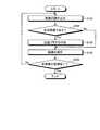
つぎに、被検体1内の画像群PGに病変画像の一例である出血画像が含まれる場合を例示して、この画像群PG内の出血画像を検出する制御部15の動作を説明する。図5は、被検体1内の画像群PGに含まれる1以上の出血画像を検出する制御部15の処理手順を例示するフローチャートである。  Next, the operation of thecontrol unit 15 that detects the bleeding image in the image group PG will be described by exemplifying a case where the image group PG in the subject 1 includes a bleeding image that is an example of a lesion image. FIG. 5 is a flowchart illustrating a processing procedure of thecontrol unit 15 that detects one or more bleeding images included in the image group PG in the subject 1.

図5に示すように、制御部15は、まず、被検体1内の画像群PGの中から処理対象の画像を読み込む(ステップS101)。この場合、制御部15は、カードI/F13に挿着された携帯型記録媒体5内の画像群PGから処理対象の画像Pn(フレーム番号n=1,2,3,…)を例えば時系列に沿って順次読み込む。As shown in FIG. 5, thecontrol unit 15 first reads an image to be processed from the image group PG in the subject 1 (step S101). In this case, thecontrol unit 15 selects, for example, an image Pn (frame number n = 1, 2, 3,...) From the image group PG in theportable recording medium 5 inserted in the card I / F 13. Read sequentially along the series.

つぎに、制御部15は、処理対象の画像として読み込んだ被検体1内の画像が出血画像であるか否かを判断する(ステップS102)。この場合、画像検出部15aは、読み込んだ処理対象の画像の色情報を検出し、検出した色情報をもとに、この処理対象の画像が出血画像であるか否かを判断する。具体的には、画像検出部15aは、この処理対象の画像の色情報として画像の平均色を検出した場合、検出した画像の平均色が出血画像の平均色に近似していれば、この処理対象の画像を被検体1内の出血画像であると判断する。一方、画像検出部15aは、この処理対象の画像の色情報として、画像を形成するRGBの各色要素の値(R値、G値、B値)を検出した場合、検出したRGBの各色要素の値が出血画像の各色要素の数値範囲内であれば、この処理対象の画像を被検体1内の出血画像であると判断する。  Next, thecontrol unit 15 determines whether or not the image in the subject 1 read as the processing target image is a bleeding image (step S102). In this case, theimage detection unit 15a detects the color information of the read processing target image, and determines whether the processing target image is a bleeding image based on the detected color information. Specifically, when the average color of the image is detected as the color information of the image to be processed, theimage detection unit 15a performs this process if the average color of the detected image approximates the average color of the bleeding image. It is determined that the target image is a bleeding image in the subject 1. On the other hand, when the value (R value, G value, B value) of each RGB color element forming the image is detected as the color information of the image to be processed, theimage detection unit 15 a If the value is within the numerical range of each color element of the bleeding image, it is determined that the image to be processed is a bleeding image in the subject 1.

制御部15は、この処理対象の画像が出血画像であると判断した場合(ステップS102,Yes)、この出血画像であると判断した処理対象の画像に対して出血フラグを付加する(ステップS103)。この場合、画像検出部15aは、上述したステップS102において出血画像であると判断した処理対象の画像(すなわち被検体1内の出血画像)に対して、出血画像である旨を示す出血フラグを付加する。このようにして、画像検出部15aは、被検体1内の画像群PGに含まれる出血画像を検出する。なお、かかる被検体1内の出血画像に付加される出血フラグは、上述した病変フラグの一例であって、出血画像である旨を示すサインである。  When thecontrol unit 15 determines that the processing target image is a bleeding image (step S102, Yes), thecontrol unit 15 adds a bleeding flag to the processing target image determined to be the bleeding image (step S103). . In this case, theimage detection unit 15a adds a bleeding flag indicating that the image is a bleeding image to the processing target image (that is, the bleeding image in the subject 1) that is determined to be a bleeding image in step S102 described above. To do. In this way, theimage detection unit 15a detects a bleeding image included in the image group PG in the subject 1. The bleeding flag added to the bleeding image in the subject 1 is an example of the above-described lesion flag, and is a sign indicating that it is a bleeding image.

つぎに、制御部15は、かかる出血フラグを付加した処理対象の画像(すなわち出血画像)を記憶部14に保存する(ステップS104)。この場合、制御部15は、かかる出血フラグを付加した出血画像を被検体1内の画像群PGの一部として記憶部14に保存する。  Next, thecontrol part 15 preserve | saves the image (namely, bleeding image) of the process target which added this bleeding flag in the memory | storage part 14 (step S104). In this case, thecontrol unit 15 stores the bleeding image to which the bleeding flag is added in the storage unit 14 as a part of the image group PG in the subject 1.

その後、制御部15は、かかる被検体1内の画像群PGに含まれる全画像を処理完了したか否かを判断する(ステップS105)。具体的には、制御部15は、カードI/F13に挿着された携帯型記録媒体5内に未だ読み込んでいない被検体1内の画像が残っている場合、あるいは、記憶部14に未だ保存していない被検体1内の画像が携帯型記録媒体5内に残っている場合、かかる被検体1内の画像群PGの処理が完了していないと判断し(ステップS105,No)、上述したステップS101に戻り、このステップS101以降の処理手順を繰り返す。  Thereafter, thecontrol unit 15 determines whether or not all the images included in the image group PG in the subject 1 have been processed (step S105). Specifically, thecontrol unit 15 stores the image in the subject 1 that has not yet been read in theportable recording medium 5 inserted in the card I / F 13 or stored in the storage unit 14. When the image in the subject 1 that has not been left remains in theportable recording medium 5, it is determined that the processing of the image group PG in the subject 1 has not been completed (No in step S105) and described above. Returning to step S101, the processing procedure after step S101 is repeated.

制御部15は、上述したステップS101〜S105の処理手順を被検体1内の画像群PGに含まれる画像毎に繰り返し行い、かかる出血フラグが付加された出血画像を含む被検体1内の画像群PGを記憶部14に保存する。  Thecontrol unit 15 repeats the processing procedure of steps S101 to S105 described above for each image included in the image group PG in the subject 1, and the image group in the subject 1 including the bleeding image to which the bleeding flag is added. PG is stored in the storage unit 14.

一方、制御部15は、カードI/F13に挿着された携帯型記録媒体5から被検体1内の画像群PGを全て読み込んだ場合、あるいは、かかる携帯型記録媒体5に保存された被検体1内の画像群PGを全て記憶部14に保存した場合、かかる画像群PG内の全画像を処理完了と判断し(ステップS105,Yes)、かかる画像群PG内の出血画像の検出処理を終了する。  On the other hand, thecontrol unit 15 reads the entire image group PG in the subject 1 from theportable recording medium 5 inserted in the card I / F 13 or the subject stored in theportable recording medium 5. When all the image groups PG in 1 are stored in the storage unit 14, it is determined that all the images in the image group PG have been processed (Yes in step S105), and the detection of the bleeding image in the image group PG is completed. To do.

なお、制御部15は、上述したステップS102において処理対象の画像が出血画像ではないと判断した場合(ステップS102,No)、上述したステップS104に進み、このステップS104以降の処理手順を繰り返す。この場合、画像検出部15aは、ステップS102において出血画像ではないと判断した被検体1内の画像(すなわち正常な臓器の画像)に対して出血フラグを付加しない。制御部15は、この出血フラグが付加されていない被検体1内の画像、すなわち正常な臓器の画像を記憶部14に保存する。すなわち、かかる出血画像ではない被検体1内の画像は、出血フラグが付加されずに、被検体1内の画像群PGの一部として記憶部14に保存される。  If thecontrol unit 15 determines in step S102 that the image to be processed is not a bleeding image (No in step S102), thecontrol unit 15 proceeds to step S104 described above, and repeats the processing procedure after step S104. In this case, theimage detection unit 15a does not add a bleeding flag to an image in the subject 1 that is determined not to be a bleeding image in Step S102 (that is, an image of a normal organ). Thecontrol unit 15 stores an image in the subject 1 to which the bleeding flag is not added, that is, an image of a normal organ in the storage unit 14. That is, an image in the subject 1 that is not such a bleeding image is stored in the storage unit 14 as a part of the image group PG in the subject 1 without adding a bleeding flag.

つぎに、被検体1内の画像群PGに病変画像の一例である出血画像が含まれる場合を例示して、かかる画像群PG内の出血画像の時間位置を示す病変マークを表示する制御を行う制御部15の動作を説明する。図6は、出血画像の計数結果に応じた表示色をもつ病変マークを表示する制御を行う制御部15の処理手順の一例を示すフローチャートである。  Next, a case where a bleeding image which is an example of a lesion image is included in the image group PG in the subject 1 is exemplified, and control is performed to display a lesion mark indicating the time position of the bleeding image in the image group PG. The operation of thecontrol unit 15 will be described. FIG. 6 is a flowchart illustrating an example of a processing procedure of thecontrol unit 15 that performs control to display a lesion mark having a display color corresponding to the count result of the bleeding image.

制御部15は、主表示領域100に表示される被検体1内の画像群PGに含まれる画像数Nの連続画像群毎に出血画像数を計数し、画像検出部15aによって検出された1以上の出血画像(すなわち出血フラグが付加された画像)を含む画像数Nの連続画像群毎に、かかる出血画像数の計数結果に応じた表示色をもつ病変マークをマーク表示部120に表示させる。  Thecontrol unit 15 counts the number of bleeding images for each of N consecutive image groups included in the image group PG in the subject 1 displayed in themain display area 100, and one or more detected by theimage detection unit 15a. A lesion mark having a display color corresponding to the count result of the number of bleeding images is displayed on themark display unit 120 for each continuous image group of the number N of images including the bleeding image (that is, the image with the bleeding flag added).

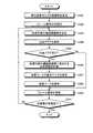
すなわち図6に示すように、制御部15は、まず、タイムバー110の単位画素当りの画像数Nを算出する(ステップS201)。具体的には、表示制御部15bは、主表示領域100に表示される被検体1内の画像群PGの全画像数A[フレーム]とタイムバー110の横サイズL[画素]とを検出する。ここで、かかるタイムバー110の横サイズLは、上述したように、タイムバー110を形成する時間軸方向の画素群(画素列)の画素数と同値である。表示制御部15bは、かかる全画像数Aを横サイズL(すなわちL画素)によって除算し、タイムバー110の単位画素当りの画像数N[フレーム/単位画素]を算出する。なお、かかる単位画素当りの画像数Nは、タイムバー110の単位画素によって代表される画像群PG内の連続画像群の画像数である。  That is, as shown in FIG. 6, thecontrol unit 15 first calculates the number N of images per unit pixel of the time bar 110 (step S201). Specifically, thedisplay control unit 15b detects the total number A [frames] of the image group PG in the subject 1 displayed in themain display region 100 and the horizontal size L [pixels] of thetime bar 110. . Here, the horizontal size L of thetime bar 110 is equal to the number of pixels of the pixel group (pixel column) in the time axis direction forming thetime bar 110 as described above. Thedisplay control unit 15b divides the total number A of images by the horizontal size L (that is, L pixels), and calculates the number N of images per unit pixel of the time bar 110 [frame / unit pixel]. Note that the number N of images per unit pixel is the number of images in the continuous image group in the image group PG represented by the unit pixel of thetime bar 110.

つぎに、制御部15は、主表示領域100に表示される被検体1内の画像群PGのフレーム番号nを初期化する(ステップS202)。この場合、表示制御部15bは、この画像群PGに含まれる画像数Nの連続画像群内の先頭画像を特定するためのフレーム番号nを初期値(例えばn=1)にする。  Next, thecontrol unit 15 initializes the frame number n of the image group PG in the subject 1 displayed in the main display area 100 (step S202). In this case, thedisplay control unit 15b sets an initial value (for example, n = 1) to the frame number n for specifying the head image in the continuous image group of the number N of images included in the image group PG.

その後、制御部15は、主表示領域100に表示される被検体1内の画像群PGの中から、出血画像数の計数処理が行われる処理対象の連続画像群を決定する(ステップS203)。この場合、表示制御部15bは、現フレーム番号nの画像を先頭画像にして画像数Nの画像が連続する画像群PG内の連続画像群(すなわち画像数Nの連続画像群)をこの処理対象の連続画像群に決定する。  Thereafter, thecontrol unit 15 determines a processing target continuous image group on which the bleeding image count processing is performed from the image group PG in the subject 1 displayed in the main display area 100 (step S203). In this case, thedisplay control unit 15b selects a continuous image group (that is, a continuous image group of N images) in the image group PG in which the image of the current frame number n is the first image and the image number N is continuous (that is, a continuous image group of N images). The continuous image group is determined.

なお、かかる処理対象の連続画像群に決定された画像数Nの連続画像群の先頭画像を特定する現フレーム番号nは、上述したステップS202において初期化したフレーム番号または後述するステップS209において更新したフレーム番号である。  Note that the current frame number n that identifies the top image of the N continuous image groups determined as the processing target continuous image group is the frame number initialized in step S202 described above or updated in step S209 described later. Frame number.

つぎに、制御部15は、ステップS203において処理対象の連続画像群に決定した画像数Nの連続画像群内の出血フラグを検索する(ステップS204)。この場合、表示制御部15bは、この画像数Nの連続画像群に含まれる各画像をフレーム番号順に順次読み込み、読み込んだ画像毎に出血フラグを検索する。ここで、この画像数Nの連続画像群に出血画像が含まれる場合、表示制御部15bは、かかる連続画像群内の出血画像を読み込むとともに、この出血画像に付加された出血フラグを読み込む。表示制御部15bは、このように出血画像とともに出血フラグを読み込むことによって、この出血画像に付加された出血フラグを検出する。すなわち、表示制御部15bは、この画像数Nの連続画像群に1以上の出血画像が含まれる場合、この画像数Nの連続画像群の中から出血画像数と同数の出血フラグを検出する。  Next, thecontrol unit 15 searches for a bleeding flag in the continuous image group of the number N of images determined as the continuous image group to be processed in step S203 (step S204). In this case, thedisplay control unit 15b sequentially reads each image included in the continuous image group of the number N of images in the order of the frame number, and searches for a bleeding flag for each read image. Here, when the bleeding image is included in the continuous image group of the number N of images, thedisplay control unit 15b reads the bleeding image in the continuous image group and also reads the bleeding flag added to the bleeding image. Thedisplay control unit 15b detects the bleeding flag added to the bleeding image by reading the bleeding flag together with the bleeding image in this way. In other words, when one or more bleeding images are included in the N number of consecutive image groups, thedisplay control unit 15b detects the same number of bleeding flags as the number of bleeding images from the N number of consecutive image groups.

続いて、制御部15は、ステップS204において検索処理した出血フラグの検索結果をもとに、この画像数Nの連続画像群における出血フラグの有無を判断する(ステップS205)。具体的には、表示制御部15bは、上述したステップS204において、この画像数Nの連続画像群の中から1以上の出血フラグを検出した場合、この画像数Nの連続画像群内に出血フラグありと判断する。  Subsequently, thecontrol unit 15 determines whether or not there is a bleeding flag in the continuous image group of the number N of images based on the search result of the bleeding flag searched in step S204 (step S205). Specifically, when thedisplay control unit 15b detects one or more bleeding flags from the continuous image group of the number N of images in step S204 described above, the bleeding flag is included in the continuous image group of the number N of images. Judge that there is.

制御部15は、このように処理対象の連続画像群である画像数Nの連続画像群内に出血フラグありと判断した場合(ステップS205,Yes)、この処理対象の連続画像群に含まれる出血画像を計数する(ステップS206)。この場合、表示制御部15bは、この処理対象の連続画像群である画像数Nの連続画像群の中から検出した出血フラグを計数する。ここで、かかる出血フラグの検出数は、上述したように、この画像数Nの連続画像群内の出血画像数と同数である。したがって、表示制御部15bは、かかる出血フラグの検出数を計数することによって、この画像数Nの連続画像群に含まれる出血画像の出血画像数x[フレーム]を得る。  When thecontrol unit 15 determines that there is a bleeding flag in the continuous image group of the image number N that is the continuous image group to be processed as described above (Yes in step S205), the bleeding included in the continuous image group to be processed. The images are counted (step S206). In this case, thedisplay control unit 15b counts the bleeding flag detected from the continuous image group of the number N of images that are the continuous image group to be processed. Here, as described above, the number of bleeding flags detected is the same as the number of bleeding images in the continuous image group of the number N of images. Therefore, thedisplay control unit 15b obtains the number of bleeding images x [frames] of bleeding images included in the continuous image group of the number N of images by counting the number of detected bleeding flags.

つぎに、制御部15は、ステップS206において得られた出血画像数xに対応して、この画像数Nの連続画像群に含まれる1以上の出血画像の時間位置を示す病変マークの表示色を設定する(ステップS207)。この場合、表示制御部15bは、この画像数Nの連続画像群内の出血画像数xを用いて病変マークの色要素を算出し、得られた色要素によって形成される色をこの病変マークの表示色に設定する。  Next, thecontrol unit 15 changes the display color of the lesion mark indicating the time position of one or more bleeding images included in the continuous image group of the number N of images corresponding to the number x of bleeding images obtained in step S206. Setting is made (step S207). In this case, thedisplay control unit 15b calculates the color element of the lesion mark using the bleeding image number x in the continuous image group of the number N of images, and sets the color formed by the obtained color element to the lesion mark. Set the display color.

具体的には、表示制御部15bは、例えば、この画像数Nの連続画像群内の出血画像数xを変数として含む次式(1)と次式(2),(3)とに基づいて、この画像数Nの連続画像群に含まれる1以上の出血画像の時間位置を示す病変マークの色要素を算出し、得られた色要素によって形成される色をこの病変マークの表示色に設定する。

R値=64+2×出血画像数x ・・・(1)
G値=0 ・・・(2)
B値=0 ・・・(3)
Specifically, thedisplay control unit 15b, for example, based on the following expressions (1) and (2) and (3) including the bleeding image number x in the continuous image group of the number N of images as a variable. The color element of the lesion mark indicating the time position of one or more bleeding images included in the continuous image group of the number N of images is calculated, and the color formed by the obtained color element is set as the display color of the lesion mark To do.

R value = 64 + 2 × the number of bleeding images x (1)
G value = 0 (2)
B value = 0 (3)

ここで、このような式(1)〜(3)に基づいて算出された色要素によって形成される色は、出血画像の示す病変(すなわち出血部位)に対応する赤色系であって、この画像数Nの連続画像群内の出血画像数xの増大に伴って濃色に変化し、この出血画像数xの減少に伴って淡色に変化する。表示制御部15bは、かかる式(1)〜(3)に基づいて病変マークの表示色を設定することによって、この画像数Nの連続画像群内の出血画像数xに応じてこの病変マークの表示色の濃淡を変化させる。  Here, the color formed by the color elements calculated based on the equations (1) to (3) is a red system corresponding to the lesion (that is, the bleeding site) indicated by the bleeding image, and this image As the number of bleeding images x in the number N of consecutive image groups increases, the color changes to dark, and as the number of bleeding images x decreases, the color changes to light. Thedisplay control unit 15b sets the display color of the lesion mark based on the formulas (1) to (3), so that the lesion mark is displayed according to the number x of bleeding images in the continuous image group of the number N of images. Change the shade of the display color.

つぎに、制御部15は、表示部12に対し、ステップS207において設定した表示色をもつ病変マークを表示する制御を行う(ステップS208)。この場合、表示制御部15bは、この画像数Nの連続画像群を代表するタイムバー110の単位画素に対応するマーク表示部120内の時間位置に、この画像数Nの連続画像群内の出血画像数xに応じた表示色(すなわちステップS207において設定した表示色)をもつ病変マークを表示する制御を行う。かかる表示制御部15bの制御に基づいて、マーク表示部120は、この画像数Nの連続画像群を代表するタイムバー110の単位画素に対応する時間位置の画素列に、この画像数Nの連続画像群内の出血画像数xに応じた表示色で病変マークを表示する。  Next, thecontrol unit 15 controls the display unit 12 to display a lesion mark having the display color set in step S207 (step S208). In this case, thedisplay control unit 15b bleeds in the continuous image group of N images at a time position in themark display unit 120 corresponding to the unit pixel of thetime bar 110 representing the continuous image group of N images. Control is performed to display a lesion mark having a display color corresponding to the number of images x (that is, the display color set in step S207). Based on the control of thedisplay control unit 15b, themark display unit 120 continuously displays the number N of images in the pixel row at the time position corresponding to the unit pixel of thetime bar 110 representing the number N of continuous images. A lesion mark is displayed in a display color corresponding to the number x of bleeding images in the image group.

続いて、制御部15は、主表示領域100に表示される被検体1内の画像群PGのフレーム番号nを更新する(ステップS209)。この場合、表示制御部15bは、現処理対象の連続画像群内の先頭画像を特定する現フレーム番号nに対して画像数N(上述したステップS201において算出した画像数)を加算し、得られた値にフレーム番号nを更新する。このように更新されたフレーム番号nは、現処理対象の連続画像群に後続する画像群PG内の次の連続画像群における先頭画像を特定する。  Subsequently, thecontrol unit 15 updates the frame number n of the image group PG in the subject 1 displayed in the main display area 100 (step S209). In this case, thedisplay control unit 15b adds the number of images N (the number of images calculated in step S201 described above) to the current frame number n that identifies the top image in the continuous image group to be processed. The frame number n is updated to the new value. The frame number n updated in this way specifies the head image in the next continuous image group in the image group PG following the continuous image group to be processed.

その後、制御部15は、主表示領域100に表示される画像群PGの全画像に対して処理完了したか否かを判断する(ステップS210)。具体的には、表示制御部15bは、上述したステップS209において更新したフレーム番号nが画像群PGの全画像数A以下である場合、この画像群PGに含まれる画像の少なくとも一つは処理未完であると判断し(ステップS210,No)、上述したステップS203に戻り、このステップS203以降の処理手順を繰り返す。  Thereafter, thecontrol unit 15 determines whether or not the processing has been completed for all the images in the image group PG displayed in the main display area 100 (step S210). Specifically, when the frame number n updated in step S209 described above is equal to or smaller than the total number A of images in the image group PG, thedisplay control unit 15b has processed at least one of the images included in the image group PG unfinished. (No in step S210), the process returns to step S203 described above, and the processing procedure after step S203 is repeated.

一方、表示制御部15bは、上述したステップS209において更新したフレーム番号nが画像群PGの全画像数Aを超えた場合、この画像群PGの全画像に対して処理完了と判断し(ステップS210,Yes)、この画像群PGに関する病変マーク表示処理を完了する。この状態において、マーク表示部120は、画像群PGに含まれる画像数Nの各連続画像群のうちの1以上の出血画像を含む連続画像群毎に、出血画像数xに応じた表示色をもつ病変マークを表示する。  On the other hand, when the frame number n updated in step S209 described above exceeds the total number A of images in the image group PG, thedisplay control unit 15b determines that the processing has been completed for all images in the image group PG (step S210). , Yes), the lesion mark display processing for this image group PG is completed. In this state, themark display unit 120 displays a display color corresponding to the bleeding image number x for each continuous image group including one or more bleeding images among the N consecutive image groups included in the image group PG. The lesion mark is displayed.

なお、制御部15は、上述したステップS205において、この処理対象の連続画像群である画像数Nの連続画像群内に出血フラグなしと判断した場合(ステップS205,No)、ステップS206〜S208の処理手順を行わずにステップS209に進む。この場合、表示制御部15bは、上述したステップS204において、この画像数Nの連続画像群の中から出血フラグを検出していない。すなわち、この画像数Nの連続画像群には、出血画像が含まれない。表示制御部15bは、この画像数Nの連続画像群に出血画像が含まれない場合、この画像数Nの連続画像群を代表するタイムバー110の単位画素に対応するマーク表示部120内の時間位置に、病変マークを表示させない。  If thecontrol unit 15 determines in step S205 described above that there is no bleeding flag in the continuous image group of the number N of images that is the continuous image group to be processed (step S205, No), the process of steps S206 to S208 is performed. The process proceeds to step S209 without performing the processing procedure. In this case, thedisplay control unit 15b has not detected a bleeding flag from the continuous image group of the number N of images in step S204 described above. That is, a bleeding image is not included in the continuous image group of the number N of images. When the bleeding image is not included in the continuous image group of the image number N, thedisplay control unit 15b displays the time in themark display unit 120 corresponding to the unit pixel of thetime bar 110 representing the continuous image group of the image number N. The lesion mark is not displayed at the position.

つぎに、被検体1内の画像群PGに含まれる出血画像の時間位置を示す病変マークM1〜M5(図3,4参照)を例示して、1以上の出血画像を含む画像群PG内の連続画像群毎に出血画像数xに応じた表示色をもつ病変マークを表示する制御を行う表示制御部15bの動作を具体的に説明する。図7は、出血画像数xに応じた表示色をもつ病変マークを表示する制御を行う表示制御部15bの動作を具体的に説明するための模式図である。  Next, the lesion marks M1 to M5 (see FIGS. 3 and 4) indicating the time positions of the bleeding images included in the image group PG in the subject 1 are exemplified, and the images in the image group PG including one or more bleeding images are illustrated. An operation of thedisplay control unit 15b that performs control to display a lesion mark having a display color corresponding to the number x of bleeding images for each continuous image group will be specifically described. FIG. 7 is a schematic diagram for specifically explaining the operation of thedisplay control unit 15b that performs control for displaying a lesion mark having a display color corresponding to the number x of bleeding images.

主表示領域100に表示される被検体1内の画像群PGは、例えば6万フレームの画像を含む画像群(すなわち全画像数Aが6万フレームである画像群)であり、複数の出血画像を含む。ここで、タイムバー110の横サイズL(すなわちタイムバー110を形成する時間軸方向の画素数)が1000画素である場合、表示制御部15bは、画像群PGの全画像数A(=6万フレーム)をタイムバー110の横サイズL(=1000画素)によって除算し、このタイムバー110の単位画素当りの画像数N(=60フレーム)を算出する。  The image group PG in the subject 1 displayed in themain display area 100 is an image group including, for example, 60,000 frame images (that is, an image group in which the total number of images A is 60,000 frames), and a plurality of bleeding images. including. Here, when the horizontal size L of the time bar 110 (that is, the number of pixels in the time axis direction forming the time bar 110) is 1000 pixels, thedisplay control unit 15b sets the total number A (= 60,000) of the image group PG. The frame) is divided by the horizontal size L (= 1000 pixels) of thetime bar 110, and the number of images N (= 60 frames) per unit pixel of thetime bar 110 is calculated.

その後、表示制御部15bは、かかる単位画素当りの画像数Nの画像が連続する画像群PG内の連続画像群を順次決定し、かかる画像数Nの連続画像群毎に出血画像数xを計数する。そして、表示制御部15bは、1以上の出血画像を含む画像数Nの連続画像群毎に、出血画像数xに応じた表示色をもつ病変マークを表示する制御を行う。  Thereafter, thedisplay control unit 15b sequentially determines a continuous image group in the image group PG in which the number N of images per unit pixel is continuous, and counts the number of bleeding images x for each continuous image group of the number N of images. To do. Then, thedisplay control unit 15b performs control to display a lesion mark having a display color corresponding to the number x of bleeding images for each of N consecutive image groups including one or more bleeding images.

具体的には図7に示すように、表示制御部15bは、単位画素当りの画像数N(=60フレーム)の画像が連続する60フレームの連続画像群Gr1を画像群PGの中から決定する。なお、この連続画像群Gr1は、タイムバー110の単位画素112aによって代表される。すなわち、この連続画像群Gr1の時間位置は、この単位画素112aに対応する。  Specifically, as shown in FIG. 7, thedisplay control unit 15b determines a continuous image group Gr1 of 60 frames in which images of the number N (= 60 frames) per unit pixel are continuous from the image group PG. . The continuous image group Gr1 is represented by theunit pixel 112a of thetime bar 110. That is, the time position of the continuous image group Gr1 corresponds to theunit pixel 112a.

表示制御部15bは、この連続画像群Gr1に対して出血フラグの検索処理を行い、この出血フラグの検索結果をもとに連続画像群Gr1の出血画像数xを計数する。例えば、この連続画像群Gr1に10フレームの出血画像が含まれる場合、表示制御部15bは、この連続画像群Gr1の中から10個の出血フラグを検出し、この出血フラグの検出数(=10)を連続画像群Gr1の出血画像数xとして計数する。このようにして、表示制御部15bは、この連続画像群Gr1の出血画像数x=10を得る。  Thedisplay control unit 15b performs a bleeding flag search process on the continuous image group Gr1, and counts the number x of bleeding images in the continuous image group Gr1 based on the search result of the bleeding flag. For example, when the continuous image group Gr1 includes 10 frames of bleeding images, thedisplay control unit 15b detects 10 bleeding flags from the continuous image group Gr1, and the number of detected bleeding flags (= 10). ) Is counted as the number x of bleeding images in the continuous image group Gr1. In this way, thedisplay control unit 15b obtains the number of bleeding images x = 10 in the continuous image group Gr1.

この連続画像群Gr1に10フレームの出血画像が含まれる場合、表示制御部15bは、この連続画像群Gr1の出血画像数x=10に応じた病変マークの表示色を設定する。具体的には、表示制御部15bは、上述した式(1)〜(3)に基づいて、出血画像数x=10に応じた色要素(R値=84、G値=0、B値=0)を算出し、得られた色要素によって形成される病変マークの表示色を設定する。  When the continuous image group Gr1 includes 10 frames of bleeding images, thedisplay control unit 15b sets the display color of the lesion mark according to the number of bleeding images x = 10 in the continuous image group Gr1. Specifically, thedisplay control unit 15b, based on the above formulas (1) to (3), the color elements (R value = 84, G value = 0, B value = corresponding to the bleeding image number x = 10). 0) is calculated, and the display color of the lesion mark formed by the obtained color element is set.

表示制御部15bは、このように設定した表示色(R値=84、G値=0、B値=0)をもつ病変マークM1を単位画素112aに対応するマーク表示部120内の時間位置に表示する制御を行う。かかる表示制御部15bの制御に基づいて、マーク表示部120は、単位画素112aに対応する時間位置に病変マークM1を表示する。  Thedisplay control unit 15b sets the lesion mark M1 having the display color (R value = 84, G value = 0, B value = 0) set in this way at the time position in themark display unit 120 corresponding to theunit pixel 112a. Control the display. Based on the control of thedisplay control unit 15b, themark display unit 120 displays the lesion mark M1 at the time position corresponding to theunit pixel 112a.

その後、表示制御部15bは、上述した連続画像群Gr1の場合と略同様に、タイムバー110の単位画素当りの画像数Nの画像が連続する画像群PG内の連続画像群Gr2〜Gr5を順次決定し、決定した連続画像群Gr2〜Gr5の各出血画像数xをそれぞれ計数する。そして、表示制御部15bは、上述した病変マークM1の場合と略同様に、かかる連続画像群Gr2〜Gr5の各出血画像数xに応じた各表示色をそれぞれもつ病変マークM2〜M5を表示する制御を行う。  Thereafter, thedisplay control unit 15b sequentially selects the continuous image groups Gr2 to Gr5 in the image group PG in which the images of the number N of images per unit pixel of thetime bar 110 are continuous, as in the case of the continuous image group Gr1 described above. The number of bleeding images x of the determined continuous image groups Gr2 to Gr5 is counted. Then, thedisplay control unit 15b displays lesion marks M2 to M5 each having a display color corresponding to the number x of bleeding images in the continuous image group Gr2 to Gr5, as in the case of the lesion mark M1 described above. Take control.

具体的には、連続画像群Gr2〜Gr5は、上述した画像数N=60フレームの画像が連続する画像群PG内の60フレームの連続画像群であり、1以上の出血画像をそれぞれ含む。また、連続画像群Gr2〜Gr5は、上述した連続画像群Gr1の後に順次連続する。すなわち、連続画像群Gr2は連続画像群Gr1に後続し、連続画像群Gr3は連続画像群Gr2に後続し、連続画像群Gr4は連続画像群Gr3に後続し、連続画像群Gr5は連続画像群Gr4に後続する。このような連続画像群Gr2〜Gr5は、タイムバー110の単位画素112b〜112eにそれぞれ代表される。すなわち、かかるタイムバー110の単位画素112b〜112eは、連続画像群Gr2〜Gr5の各時間位置にそれぞれ対応する。  Specifically, the continuous image groups Gr2 to Gr5 are continuous image groups of 60 frames in the image group PG in which the above-mentioned image number N = 60 frames are continuous, and each include one or more bleeding images. Further, the continuous image groups Gr2 to Gr5 are sequentially continued after the above-described continuous image group Gr1. That is, the continuous image group Gr2 follows the continuous image group Gr1, the continuous image group Gr3 follows the continuous image group Gr2, the continuous image group Gr4 follows the continuous image group Gr3, and the continuous image group Gr5 is the continuous image group Gr4. Followed by. Such continuous image groups Gr2 to Gr5 are represented byunit pixels 112b to 112e of thetime bar 110, respectively. That is, theunit pixels 112b to 112e of thetime bar 110 correspond to the respective time positions of the continuous image groups Gr2 to Gr5.

また、表示制御部15bは、連続画像群Gr2〜Gr5内の各出血フラグの検出数を順次計数し、連続画像群Gr2の出血画像数x=25、連続画像群Gr3の出血画像数x=50、連続画像群Gr4の出血画像数x=15、および連続画像群Gr5の出血画像数x=5を順次取得する。このような表示制御部15bは、上述した式(1)〜(3)に基づいて、連続画像群Gr2の出血画像数x=25に応じた病変マークM2の表示色(R値=114、G値=0、B値=0)と、連続画像群Gr3の出血画像数x=50に応じた病変マークM3の表示色(R値=164、G値=0、B値=0)と、連続画像群Gr4の出血画像数x=15に応じた病変マークM4の表示色(R値=94、G値=0、B値=0)と、連続画像群Gr5の出血画像数x=5に応じた病変マークM5の表示色(R値=74、G値=0、B値=0)とを順次設定する。  Further, thedisplay control unit 15b sequentially counts the number of detected bleeding flags in the continuous image groups Gr2 to Gr5, the number of bleeding images x = 25 in the continuous image group Gr2, and the number of bleeding images x = 50 in the continuous image group Gr3. The bleeding image number x = 15 of the continuous image group Gr4 and the bleeding image number x = 5 of the continuous image group Gr5 are sequentially acquired. Such adisplay control unit 15b displays the lesion mark M2 according to the bleeding image count x = 25 in the continuous image group Gr2 (R value = 114, G) based on the above-described equations (1) to (3). Value = 0, B value = 0), the display color of the lesion mark M3 (R value = 164, G value = 0, B value = 0) corresponding to the number of bleeding images x = 50 in the continuous image group Gr3, and continuous According to the display color (R value = 94, G value = 0, B value = 0) of the lesion mark M4 corresponding to the bleeding image number x = 15 of the image group Gr4 and the bleeding image number x = 5 of the continuous image group Gr5 The display colors of the lesion mark M5 (R value = 74, G value = 0, B value = 0) are sequentially set.

表示制御部15bは、かかる出血画像数xに応じた表示色をもつ病変マークM2〜M5を単位画素112b〜112eにそれぞれ対応するマーク表示部120内の各時間位置に順次表示する制御を行う。かかる表示制御部15bの制御に基づいて、マーク表示部120は、単位画素112b〜112eにそれぞれ対応する各時間位置に病変マークM2〜M5を順次表示する。  Thedisplay control unit 15b performs control to sequentially display lesion marks M2 to M5 having display colors corresponding to the bleeding image number x at respective time positions in themark display unit 120 corresponding to theunit pixels 112b to 112e, respectively. Based on the control of thedisplay control unit 15b, themark display unit 120 sequentially displays lesion marks M2 to M5 at respective time positions corresponding to theunit pixels 112b to 112e, respectively.

ここで、かかる表示制御部15bの制御に基づいて表示される病変マークM1〜M5は、連続画像群Gr1〜Gr5のそれぞれに含まれる各出血画像群をそれぞれ代表し、タイムバー110の単位画素112a〜112eに対応するマーク表示部120内の各画素列によってそれぞれ形成される。また、病変マークM1は、連続画像群Gr1の出血画像数x=10に応じた表示色(R値=84、G値=0、B値=0)を有し、病変マークM2は、連続画像群Gr2の出血画像数x=25に応じた表示色(R値=114、G値=0、B値=0)を有し、病変マークM3は、連続画像群Gr3の出血画像数x=50に応じた表示色(R値=164、G値=0、B値=0)を有する。病変マークM4は、連続画像群Gr4の出血画像数x=15に応じた表示色(R値=94、G値=0、B値=0)を有し、病変マークM5は、連続画像群Gr5の出血画像数x=5に応じた表示色(R値=74、G値=0、B値=0)を有する。  Here, the lesion marks M1 to M5 displayed based on the control of thedisplay control unit 15b represent each bleeding image group included in each of the continuous image groups Gr1 to Gr5, and theunit pixel 112a of thetime bar 110. To 112e, each of the pixel columns in themark display unit 120 is formed. The lesion mark M1 has a display color (R value = 84, G value = 0, B value = 0) corresponding to the number of bleeding images x = 10 in the continuous image group Gr1, and the lesion mark M2 is a continuous image. The display color (R value = 114, G value = 0, B value = 0) corresponding to the number of bleeding images x = 25 in the group Gr2, and the lesion mark M3 is the number of bleeding images x = 50 in the continuous image group Gr3. Display colors (R value = 164, G value = 0, B value = 0). The lesion mark M4 has a display color (R value = 94, G value = 0, B value = 0) corresponding to the number of bleeding images x = 15 in the continuous image group Gr4, and the lesion mark M5 is the continuous image group Gr5. Display colors (R value = 74, G value = 0, B value = 0) corresponding to the number of bleeding images x = 5.

かかる病変マークM1〜M5の各表示色は、出血画像の示す出血部位に対応する赤色(すなわち出血部位を連想し易い色)であり、上述した連続画像群Gr1〜Gr5の各出血画像数xの増大に伴って濃くなる。具体的には、出血画像数x=50の出血画像を代表する病変マークM3の表示色は、50フレーム未満の出血画像を代表する病変マークM1,M2,M4,M5に比して濃い赤色である。出血画像数x=25の出血画像を代表する病変マークM2の表示色は、25フレーム未満の出血画像を代表する病変マークM1,M4,M5に比して濃い赤色である。出血画像数x=15の出血画像を代表する病変マークM4の表示色は、15フレーム未満の出血画像を代表する病変マークM1,M5に比して濃い赤色である。出血画像数x=10の出血画像を代表する病変マークM1の表示色は、10フレーム未満の出血画像を代表する病変マークM5に比して濃い赤色である。  Each display color of the lesion marks M1 to M5 is red corresponding to the bleeding site indicated by the bleeding image (that is, a color that easily associates the bleeding site), and the number x of each bleeding image in the continuous image group Gr1 to Gr5 described above. It becomes darker as it increases. Specifically, the display color of the lesion mark M3 representing the bleeding image having the number of bleeding images x = 50 is darker red than the lesion marks M1, M2, M4, and M5 representing the bleeding image of less than 50 frames. is there. The display color of the lesion mark M2 representing the bleeding image with the number of bleeding images x = 25 is dark red compared to the lesion marks M1, M4, and M5 representing the bleeding image of less than 25 frames. The display color of the lesion mark M4 representing the bleeding image having the number of bleeding images x = 15 is dark red compared to the lesion marks M1 and M5 representing the bleeding image of less than 15 frames. The display color of the lesion mark M1 representing the bleeding image with the number of bleeding images x = 10 is dark red compared to the lesion mark M5 representing the bleeding image of less than 10 frames.

このような病変マークM1〜M5は、連続画像群Gr1〜Gr5のそれぞれに含まれる出血画像の各時間位置をタイムバー110に沿って示すとともに、各表示色(具体的には赤色)の濃さによって、連続画像群Gr1〜Gr5の各出血画像数の分布をタイムバー110に沿って示すことができる。この場合、病変マークM1〜M5は、各病変マーク間での表示色の濃さの違いによって、連続画像群Gr1〜Gr5間で比較される出血画像数の多少を示すことができる。  Such lesion marks M1 to M5 indicate the time positions of the bleeding images included in each of the continuous image groups Gr1 to Gr5 along thetime bar 110 and the darkness of each display color (specifically, red). Thus, the distribution of the number of bleeding images in the continuous image groups Gr1 to Gr5 can be shown along thetime bar 110. In this case, the lesion marks M1 to M5 can indicate the number of bleeding images to be compared between the consecutive image groups Gr1 to Gr5 depending on the difference in display color density between the lesion marks.

医者または看護師等のユーザは、タイムバー110に沿って表示された病変マークM1〜M5の表示位置によって、画像群PGの全体的な時間位置内の何れの時間位置に出血画像が分布しているかを理解できる。これと同時に、ユーザは、かかる病変マークM1〜M5の表示色によって、画像群PGの全体的な時間位置における出血画像数の分布を容易に理解できるとともに、かかる出血画像の時間位置の間で比較される出血画像数の多少を容易に理解できる。  A user such as a doctor or a nurse distributes a bleeding image at any time position in the overall time position of the image group PG depending on the display positions of the lesion marks M1 to M5 displayed along thetime bar 110. I can understand. At the same time, the user can easily understand the distribution of the number of bleeding images at the entire time position of the image group PG by the display colors of the lesion marks M1 to M5, and compare the time positions of the bleeding images. You can easily understand the number of bleeding images.

なお、上述した表示制御部15bは、図3に示した表示操作アイコン群130の操作によって入力される表示指示情報をもとに、主表示領域100に画像群PG内の画像Pn(フレーム番号n=1,2,3,…)を表示する制御を行う。具体的には、入力部11は、上述した表示操作アイコン群130のうちの所望のアイコンをクリック操作することによって、かかる所望のアイコンに対応する表示指示情報を制御部15に入力する。表示制御部15bは、かかる入力部11によって入力された表示指示情報に基づいて、画像群PG内の画像Pnを主表示領域100に表示する制御を行う。Note that thedisplay control unit 15b described above displays the image Pn (frame number) in the image group PG in themain display area 100 based on the display instruction information input by operating the displayoperation icon group 130 shown in FIG. (n = 1, 2, 3,...) is displayed. Specifically, theinput unit 11 inputs display instruction information corresponding to the desired icon to thecontrol unit 15 by clicking the desired icon in the displayoperation icon group 130 described above. Thedisplay control unit 15 b performs control to display the image Pn in the image group PG in themain display area 100 based on the display instruction information input by theinput unit 11.

例えば、表示制御部15bは、再生アイコン131のクリック操作が行われた場合、主表示領域100に被検体1内の画像Pnを時系列の順方向に沿って順次表示させ、コマ再生アイコン132のクリック操作が行われた場合、その都度、主表示領域100に被検体1内の画像Pnを時系列の順方向に沿って1フレームずつ表示させる。また、表示制御部15bは、逆再生アイコン134のクリック操作が行われた場合、主表示領域100に被検体1内の画像Pnを時系列の逆方向に沿って順次表示させ、逆コマ再生アイコン135のクリック操作が行われた場合、その都度、主表示領域100に被検体1内の画像Pnを時系列の逆方向に沿って1フレームずつ表示させる。For example, when the reproduction icon 131 is clicked, thedisplay control unit 15 b sequentially displays the images Pn in the subject 1 in themain display area 100 along the time series forward direction, and the frame reproduction icon 132. Is clicked, the image Pn in the subject 1 is displayed in themain display area 100 frame by frame along the forward direction in time series. In addition, when thereverse playback icon 134 is clicked, thedisplay control unit 15b sequentially displays the images Pn in the subject 1 in themain display area 100 along the reverse direction in time series, and reverse frame playback. Each time the icon 135 is clicked, the image Pn in the subject 1 is displayed in themain display area 100 frame by frame along the reverse direction of the time series.

一方、表示制御部15bは、頭出しアイコン133のクリック操作が行われた場合、被検体1内の画像群PGのうちの最後に撮像された画像を主表示領域100に表示させる。また、表示制御部15bは、逆頭出しアイコン136のクリック操作が行われた場合、被検体1内の画像群PGのうちの最初に撮像された画像を主表示領域100に表示させる。  On the other hand, when the cue icon 133 is clicked, thedisplay control unit 15 b causes themain display region 100 to display the last image captured in the image group PG in the subject 1. In addition, when thereverse operation icon 136 is clicked, thedisplay control unit 15 b displays the first captured image in the image group PG in the subject 1 in themain display area 100.

以上、説明したように、本発明の実施の形態1では、時系列に沿って臓器内部を撮像した被検体内の画像群に含まれる1以上の出血画像を検出し、この被検体内の画像群の全体的な時間位置を示すタイムバーを形成する時間軸方向の画素数をこの被検体内の画像群の全画像数によって除算して、このタイムバーの単位画素当りの画像数を算出し、この被検体内の画像群内においてこの単位画素当りの画像数の画像が連続する連続画像群毎に出血画像数を計数し、1以上の出血画像を含む連続画像群毎に、連続画像群内の出血画像の時間位置を示す病変マークをこの連続画像群の出血画像数に応じた表示色(例えば出血画像数に応じて異なる濃さの表示色)で表示するように構成した。このため、かかるタイムバーに沿って表示された1以上の病変マークの表示位置によって、被検体内の画像群の全体的な時間位置内における出血画像の時間位置を示すことができるとともに、かかる1以上の病変マークの表示色によって、この全体的な時間位置内における出血画像数の分布を示すことができる。この結果、時系列に沿って撮像された臓器内部の画像群に含まれる出血画像等の病変画像の時間位置を理解できるとともに、臓器内部の画像群の全体的な時間位置における病変画像数の分布を容易に理解できる画像表示装置を実現することができる。  As described above, in the first embodiment of the present invention, one or more bleeding images included in an image group in a subject obtained by imaging the inside of an organ in time series are detected, and the image in the subject is detected. Divide the number of pixels in the time axis direction to form the time bar indicating the overall time position of the group by the total number of images in the image group in the subject to calculate the number of images per unit pixel of this time bar. The number of bleeding images is counted for each continuous image group in which the number of images per unit pixel is continuous in the image group in the subject, and the continuous image group is included for each continuous image group including one or more bleeding images. The lesion mark indicating the time position of the bleeding image is displayed in a display color corresponding to the number of bleeding images in the continuous image group (for example, a display color having a different density depending on the number of bleeding images). For this reason, the time position of the bleeding image within the overall time position of the image group in the subject can be indicated by the display position of one or more lesion marks displayed along the time bar. The distribution of the number of bleeding images within this overall time position can be indicated by the display color of the lesion mark. As a result, the time position of a lesion image such as a bleeding image included in an image group inside the organ imaged in time series can be understood, and the distribution of the number of lesion images at the entire time position of the image group inside the organ An image display device that can easily understand the above can be realized.

この実施の形態1にかかる画像表示装置を用いることによって、ユーザは、被検体内の画像群に含まれる1以上の病変画像の時間位置を理解でき、かかる時間位置をもとに、病変画像が撮像された被検体内の臓器を容易に推測できる。これに加えて、ユーザは、被検体内の画像群の全体的な時間位置における病変画像数の分布を容易に理解でき、この被検体内の画像群に含まれる病変画像の実際の画像数に近似する病変画像数を容易に推測することができる。  By using the image display apparatus according to the first embodiment, the user can understand the time positions of one or more lesion images included in the image group in the subject, and the lesion images are obtained based on the time positions. The organ in the imaged subject can be easily estimated. In addition, the user can easily understand the distribution of the number of lesion images in the entire time position of the image group in the subject, and the actual number of lesion images included in the image group in the subject. The number of approximate lesion images can be easily estimated.

(実施の形態2)
つぎに、本発明の実施の形態2について説明する。上述した実施の形態1では、タイムバー110の単位画素当りの画像数Nの画像が連続する連続画像群毎に計数した出血画像数xに応じて病変マークの表示色を変化させていたが、この実施の形態2では、かかる出血画像数xに応じて病変マークの表示サイズを変化させている。
(Embodiment 2)
Next, a second embodiment of the present invention will be described. In Embodiment 1 described above, the display color of the lesion mark is changed according to the number x of bleeding images counted for each continuous image group in which the number N of images per unit pixel of thetime bar 110 is continuous. In the second embodiment, the display size of the lesion mark is changed according to the number x of bleeding images.

図8は、本発明の実施の形態2にかかる画像表示装置の一構成例を模式的に示すブロック図である。図8に示すように、この実施の形態2にかかる画像表示装置20は、上述した実施の形態1にかかる画像表示装置4の制御部15に代えて制御部25を有する。かかる画像表示装置20において、表示部12のマーク表示部120は、画像群PG内の画像数Nの連続画像群毎に計数された出血画像数xに応じて表示色を変化させた病変マークに代えて、かかる出血画像数xに応じて表示サイズを変化させた病変マークを表示する。また、本発明の実施の形態2にかかる被検体内情報取得システムは、上述した実施の形態1にかかる被検体内情報取得システム(図1参照)の画像表示装置4に代えて画像表示装置20を有する。その他の構成は実施の形態1と同じであり、同一構成部分には同一符号を付している。  FIG. 8 is a block diagram schematically illustrating a configuration example of an image display apparatus according to the second embodiment of the present invention. As illustrated in FIG. 8, theimage display device 20 according to the second embodiment includes acontrol unit 25 instead of thecontrol unit 15 of the image display device 4 according to the first embodiment described above. In theimage display device 20, themark display unit 120 of the display unit 12 changes to a lesion mark whose display color is changed according to the number x of bleeding images counted for each of N consecutive images in the image group PG. Instead, a lesion mark whose display size is changed in accordance with the number x of bleeding images is displayed. The in-subject information acquisition system according to the second exemplary embodiment of the present invention is animage display device 20 instead of the image display device 4 of the in-subject information acquisition system (see FIG. 1) according to the first exemplary embodiment described above. Have Other configurations are the same as those of the first embodiment, and the same reference numerals are given to the same components.

制御部25は、1以上の出血画像を含む画像群PG内の画像数Nの連続画像群毎に出血画像数xに応じた表示サイズの病変マークを表示する制御を行うマーク表示制御機能以外、上述した実施の形態1にかかる画像表示装置4の制御部15と同様の機能を有する。このような制御部25は、実施の形態1にかかる画像表示装置4の制御部15と同様に画像検出部15aを有し、上述した表示制御部15bに代えて表示制御部25bを有する。  In addition to the mark display control function, thecontrol unit 25 performs control to display a lesion mark having a display size corresponding to the bleeding image number x for each of the N consecutive image groups in the image group PG including one or more bleeding images. It has the same function as thecontrol unit 15 of the image display device 4 according to the first embodiment described above. Similar to thecontrol unit 15 of the image display apparatus 4 according to the first embodiment, thecontrol unit 25 includes animage detection unit 15a, and includes adisplay control unit 25b instead of thedisplay control unit 15b described above.

表示制御部25bは、被検体1内の画像群PGに含まれる1以上の病変画像(例えば出血画像)の時間位置を示す病変マークを表示部12のマーク表示部120に表示する制御を行う。具体的には、表示制御部25bは、上述した実施の形態1の表示制御部15bと同様に、タイムバー110の単位画素当りの画像数Nを算出し、かかる画像数Nの画像が連続する画像群PG内の連続画像群毎に出血画像数xを計数する。表示制御部25bは、かかる画像数Nの連続画像群毎に計数した出血画像数xが1以上である場合、すなわち、かかる画像数Nの連続画像群に1以上の出血画像が含まれる場合、その都度、この1以上の出血画像を含む連続画像群の出血画像数xに応じた表示サイズをもつ病変マークをマーク表示部120に表示させる。この場合、表示制御部25bは、出血画像の示す出血部位に対応する赤色系(出血部位を連想し易い色)を病変マークの表示色に設定し、この赤色系の表示色をもつ病変マークの表示サイズを出血画像数xの増大に伴って大きくする。  Thedisplay control unit 25 b performs control to display a lesion mark indicating the time position of one or more lesion images (for example, bleeding images) included in the image group PG in the subject 1 on themark display unit 120 of the display unit 12. Specifically, thedisplay control unit 25b calculates the number N of images per unit pixel of thetime bar 110 in the same manner as thedisplay control unit 15b of the first embodiment described above, and the images of the number N are continuous. The number x of bleeding images is counted for each continuous image group in the image group PG. When the bleeding image count x counted for each continuous image group of the number N of images is 1 or more, that is, when one or more bleeding images are included in the continuous image group of the number N of images, Each time, a lesion mark having a display size corresponding to the number x of bleeding images in the continuous image group including one or more bleeding images is displayed on themark display unit 120. In this case, thedisplay control unit 25b sets a red color corresponding to the bleeding site indicated by the bleeding image (a color easily associated with the bleeding site) as the display color of the lesion mark, and the lesion mark having the red display color is displayed. The display size is increased as the number of bleeding images x increases.

なお、表示制御部25bは、このように出血画像数xに応じて表示サイズを変化させた病変マークをマーク表示部120に表示させるマーク表示制御機能以外、上述した実施の形態1の表示制御部15bと同様の機能を有する。  Thedisplay control unit 25b is the display control unit of the first embodiment described above except for the mark display control function that causes themark display unit 120 to display the lesion mark whose display size has been changed according to the number x of bleeding images. It has the same function as 15b.

つぎに、被検体1の画像群PGに含まれる病変画像が出血画像である場合を例示して、本発明の実施の形態2にかかる画像表示装置20の表示部12の表示内容を具体的に説明する。図9は、実施の形態2にかかる画像表示装置20の表示部12の表示内容を例示する模式図である。  Next, the case where the lesion image included in the image group PG of the subject 1 is a bleeding image is exemplified, and the display content of the display unit 12 of theimage display device 20 according to the second embodiment of the present invention is specifically described. explain. FIG. 9 is a schematic view illustrating the display contents of the display unit 12 of theimage display apparatus 20 according to the second embodiment.

図9に示すように、この画像表示装置20の表示部12に表示されるウィンドウWにおいて、マーク表示部120は、画像数Nの連続画像群の出血画像数xに応じた表示色をもつ1以上の病変マーク(例えば上述した病変マーク群120a,120b)に代えて、かかる出血画像数xに応じた表示サイズをもつ1以上の病変マークを含む病変マーク群220a,220bを表示する。なお、かかる病変マーク群220a,220bを表示するマーク表示部120は、上述した実施の形態1の場合と同様に、時間軸方向の横サイズL[画素]と時間軸方向に対して垂直方向の縦サイズT[画素]とによって規定される矩形領域内に格子状に配列された(L×T)画素の画素群によって形成される。かかるマーク表示部120を含むウィンドウWの他の表示内容は、上述した実施の形態1の場合と同じである。  As shown in FIG. 9, in the window W displayed on the display unit 12 of theimage display device 20, themark display unit 120 has a display color corresponding to the bleeding image number x of the continuous image group of N images. Instead of the above lesion marks (for example, thelesion mark groups 120a and 120b described above),lesion mark groups 220a and 220b including one or more lesion marks having a display size corresponding to the bleeding image number x are displayed. Note that themark display unit 120 that displays thelesion mark groups 220a and 220b has a horizontal size L [pixel] in the time axis direction and a direction perpendicular to the time axis direction, as in the case of the first embodiment. It is formed by a pixel group of (L × T) pixels arranged in a grid within a rectangular area defined by the vertical size T [pixel]. Other display contents of the window W including themark display unit 120 are the same as those in the first embodiment.

病変マーク群220a,220bは、タイムバー110の単位画素に対応して表示される病変マークをそれぞれ複数含むものである。かかる病変マーク群220a,220bに含まれる複数の病変マークのそれぞれは、マーク表示部120内の縦方向の画素列(すなわちタイムバー110の時間軸に直交する方向の画素列)に含まれる1以上の画素によって形成され、画像群PG内の画像数Nの連続画像群毎に表示制御部25bが計数した出血画像数xに応じた表示サイズをもつ。  Thelesion mark groups 220a and 220b include a plurality of lesion marks displayed corresponding to the unit pixels of thetime bar 110, respectively. Each of the plurality of lesion marks included in thelesion mark groups 220a and 220b is one or more included in a vertical pixel column (that is, a pixel column in a direction perpendicular to the time axis of the time bar 110) in themark display unit 120. And a display size corresponding to the number x of bleeding images counted by thedisplay control unit 25b for each of N consecutive images in the image group PG.

つぎに、上述したマーク表示部120内の病変マーク群220aを例示し、表示制御部25bの制御に基づいてマーク表示部120が表示する病変マークを詳細に説明する。図10は、実施の形態2にかかる画像表示装置20の表示制御部25bがマーク表示部120に表示させる病変マークの一具体例を示す模式図である。なお、図10には、マーク表示部120によって表示された病変マーク群220aの拡大図が示される。  Next, thelesion mark group 220a in themark display unit 120 described above is illustrated, and the lesion mark displayed by themark display unit 120 based on the control of thedisplay control unit 25b will be described in detail. FIG. 10 is a schematic diagram illustrating a specific example of a lesion mark displayed on themark display unit 120 by thedisplay control unit 25b of theimage display apparatus 20 according to the second embodiment. FIG. 10 shows an enlarged view of thelesion mark group 220a displayed by themark display unit 120.

図10に示すように、病変マーク群220aは、例えば、タイムバー110を形成する時間軸方向の画素列に沿って表示された5つの病変マークM6〜M10を含むものである。病変マークM6〜M10は、タイムバー110の単位画素112a〜112eのそれぞれに対応して表示される。このような病変マークM6〜M10は、かかる単位画素112a〜112eのそれぞれに代表される画像群PG内の画像数Nの各連続画像群にそれぞれ含まれる1以上の出血画像の時間位置をそれぞれ示す。  As shown in FIG. 10, thelesion mark group 220 a includes, for example, five lesion marks M <b> 6 to M <b> 10 displayed along the pixel column in the time axis direction that forms thetime bar 110. The lesion marks M6 to M10 are displayed corresponding to theunit pixels 112a to 112e of thetime bar 110, respectively. Such lesion marks M6 to M10 respectively indicate the time positions of one or more bleeding images included in each of the consecutive image groups of the number N of images in the image group PG represented by each of theunit pixels 112a to 112e. .

具体的には、病変マークM6〜M10は、時間軸方向の垂直方向に一次元配列されたマーク表示部120内の画素群(すなわちタイムバー110の時間軸に直交する方向の画素列)に含まれる1以上の画素によってそれぞれ形成される。この場合、かかる病変マークM6を形成する1以上の画素は、タイムバー110の単位画素112aに対応してマーク表示部120の一底辺から時間軸方向の垂直方向(すなわちマーク表示部120の縦方向)に配列される。これと同様に、かかる病変マークM7〜M10をそれぞれ形成する1以上の各画素は、タイムバー110の単位画素112b〜112eにそれぞれ対応してマーク表示部120の一底辺から時間軸方向の垂直方向に配列される。  Specifically, the lesion marks M6 to M10 are included in a pixel group in themark display unit 120 that is one-dimensionally arranged in the vertical direction in the time axis direction (that is, a pixel column in a direction orthogonal to the time axis of the time bar 110). Each pixel is formed by one or more pixels. In this case, one or more pixels forming the lesion mark M6 correspond to theunit pixel 112a of thetime bar 110 from the bottom side of themark display unit 120 in the vertical direction in the time axis direction (that is, the vertical direction of the mark display unit 120). ). Similarly, one or more pixels that form the lesion marks M7 to M10 respectively correspond to theunit pixels 112b to 112e of thetime bar 110 from the bottom side of themark display unit 120 in the vertical direction in the time axis direction. Arranged.

このような病変マークM6は、タイムバー110の単位画素112aによって代表される画像群PG内の連続画像群(上述した画像数Nの連続画像群)に含まれる1以上の出血画像を代表するとともに、かかる単位画素112aに代表される連続画像群内の出血画像の時間位置を一括して示す。これと同様に、病変マークM7〜M10は、タイムバー110の単位画素112b〜112eのそれぞれによって代表される画像数Nの各連続画像群内の1以上の出血画像をそれぞれ代表するとともに、かかる単位画素112b〜112eのそれぞれに代表される各連続画像群内の出血画像の時間位置をそれぞれ一括して示す。  Such a lesion mark M6 represents one or more bleeding images included in the continuous image group (continuous image group of the above-described number N of images) in the image group PG represented by theunit pixel 112a of thetime bar 110. The time positions of the bleeding images in the continuous image group represented by theunit pixel 112a are collectively shown. Similarly, the lesion marks M7 to M10 represent one or more bleeding images in each of the consecutive image groups of the number N of images represented by theunit pixels 112b to 112e of thetime bar 110, respectively, and the units The time positions of the bleeding images in each continuous image group represented by each of thepixels 112b to 112e are collectively shown.

また、このような病変マークM6〜M10の表示サイズは、タイムバー110の単位画素112a〜112eのそれぞれによって代表される画像数Nの各連続画像群内の出血画像数xに応じて異なる。具体的には、かかる病変マークM6〜M10の各表示サイズは、単位画素112a〜112eがそれぞれ代表する画像数Nの各連続画像群内の出血画像数xの増大に伴って大きくなり、かかる出血画像数xの減少に伴って小さくなる。すなわち、タイムバー110の時間軸に直交する病変マークM6〜M10の各画素数は、単位画素112a〜112eがそれぞれ代表する画像数Nの各連続画像群内の出血画像数xの増大に伴って増大し、かかる出血画像数xの減少に伴って減少する。この場合、かかる病変マークM6〜M10の各画像数の上限値は、マーク表示部120の縦サイズT[画素]と同値である。  The display sizes of such lesion marks M6 to M10 differ according to the number x of bleeding images in each continuous image group of the number N of images represented by theunit pixels 112a to 112e of thetime bar 110. Specifically, the display sizes of the lesion marks M6 to M10 increase with an increase in the number of bleeding images x in each continuous image group of the number N of images represented by theunit pixels 112a to 112e, respectively. It becomes smaller as the number of images x decreases. That is, the number of pixels of the lesion marks M6 to M10 orthogonal to the time axis of thetime bar 110 increases as the number of bleeding images x in each continuous image group of the number of images N represented by theunit pixels 112a to 112e respectively increases. It increases and decreases as the number of bleeding images x decreases. In this case, the upper limit value of the number of images of the lesion marks M6 to M10 is the same value as the vertical size T [pixel] of themark display unit 120.

このような病変マークM6〜M10は、1以上の出血画像を含む画像群PG内の画像数Nの連続画像群毎に出血画像の時間位置を示すとともに、その表示サイズ(縦サイズTを上限値として変化する病変マークの画素数)によって、かかる画像数Nの連続画像群毎に出血画像数の分布を示す。以上のことは、上述した病変マーク群220bについても同様である。  Such lesion marks M6 to M10 indicate the time position of the bleeding image for each of the N consecutive image groups in the image group PG including one or more bleeding images, and display the size (vertical size T as the upper limit value). Distribution of the number of bleeding images for each continuous image group of the number N of images. The same applies to thelesion mark group 220b described above.

なお、上述したように出血画像数xに応じて表示サイズが変化する病変マーク(例えば病変マークM6〜M10)の表示色は、所望の色であってもよいが、出血画像の示す出血部位に対応する赤色系であることが望ましい。何故ならば、かかる病変マークの表示色を赤色系にすることによって、出血画像の示す出血部位を連想し易くなるからである。  As described above, the display color of a lesion mark (for example, lesion marks M6 to M10) whose display size changes in accordance with the number x of bleeding images may be a desired color, but the bleeding color indicated by the bleeding image The corresponding red color is desirable. This is because by making the display color of the lesion mark red, it is easier to associate the bleeding site indicated by the bleeding image.

また、このような病変マークを表示するマーク表示部120の背景(すなわち横サイズLと縦サイズTとによって規定される矩形領域)の明度は、病変マークとウィンドウWの背景との中間近傍の値であることが望ましく、かかるマーク表示部120の背景色は、病変マークに対して補色であることが望ましい。これによって、かかるマーク表示部120の背景と病変マークとの境界を明確化することができ、この結果、マーク表示部120が医師または看護師等のユーザに視認し易い態様の病変マークを表示できるからである。  Further, the brightness of the background of themark display unit 120 for displaying such a lesion mark (that is, a rectangular region defined by the horizontal size L and the vertical size T) is a value in the vicinity of the middle between the lesion mark and the background of the window W. The background color of themark display unit 120 is preferably a complementary color to the lesion mark. As a result, the boundary between the background of themark display unit 120 and the lesion mark can be clarified. As a result, themark display unit 120 can display a lesion mark in a form that is easily visible to a user such as a doctor or a nurse. Because.

つぎに、被検体1内の画像群PGに病変画像の一例である出血画像が含まれる場合を例示して、かかる画像群PG内の出血画像の時間位置を示す病変マークを表示する制御を行う制御部25の動作を説明する。図11は、出血画像の計数結果に応じた表示サイズをもつ病変マークを表示する制御を行う制御部25の処理手順の一例を示すフローチャートである。  Next, a case where a bleeding image which is an example of a lesion image is included in the image group PG in the subject 1 is exemplified, and control is performed to display a lesion mark indicating the time position of the bleeding image in the image group PG. The operation of thecontrol unit 25 will be described. FIG. 11 is a flowchart illustrating an example of a processing procedure of thecontrol unit 25 that performs control to display a lesion mark having a display size corresponding to the count result of the bleeding image.

制御部25は、上述したステップS201〜S210の処理手順(図6参照)と略同様の処理手順を行って、主表示領域100に表示される被検体1内の画像群PGに含まれる画像数Nの連続画像群毎に出血画像数xを計数し、かかる出血画像数xの計数結果に応じた表示サイズをもつ病変マークをマーク表示部120に表示させる。この場合、制御部25は、上述したステップS207,S208の処理手順に代えて、処理対象の連続画像群である画像数Nの連続画像群の出血画像数xに応じた病変マークの表示サイズを設定し、この設定した表示サイズをもつ病変マークをマーク表示部120に表示させる。  Thecontrol unit 25 performs a processing procedure substantially similar to the processing procedure of steps S201 to S210 described above (see FIG. 6), and the number of images included in the image group PG in the subject 1 displayed in themain display region 100. The number of bleeding images x is counted for each of N consecutive image groups, and a lesion mark having a display size corresponding to the counting result of the number of bleeding images x is displayed on themark display unit 120. In this case, instead of the processing procedure of steps S207 and S208 described above, thecontrol unit 25 changes the display size of the lesion mark according to the bleeding image number x of the continuous image group of the image number N that is the continuous image group to be processed. The lesion mark having the set display size is displayed on themark display unit 120.

具体的には図11に示すように、表示制御部25bは、上述したステップS201〜S204と同様に、タイムバー110の単位画素当りの画像数Nを算出し(ステップS302)、被検体1内の画像群PGのフレーム番号nを初期化し(ステップS302)、この画像数Nの画像が連続する画像群PG内の連続画像群を処理対象の連続画像群に決定し(ステップS303)、この処理対象の連続画像群である画像数Nの連続画像群内の出血フラグを検索する(ステップS304)。  Specifically, as shown in FIG. 11, thedisplay control unit 25b calculates the number N of images per unit pixel of thetime bar 110 in the same manner as the above-described steps S201 to S204 (step S302). The frame number n of the image group PG is initialized (step S302), and the continuous image group in the image group PG in which the number N of images is continuous is determined as the processing target continuous image group (step S303). A bleeding flag is searched for in the continuous image group of the number N of images, which is the target continuous image group (step S304).

続いて、表示制御部25bは、上述したステップS305,S306と同様に、この画像数Nの連続画像群における出血フラグの有無を判断し(ステップS305)、出血フラグありと判断した場合(ステップ305,Yes)、この画像数Nの連続画像群に含まれる出血画像を計数し(ステップS306)、この処理対象の画像群である画像数Nの連続画像群の出血画像数xを得る。  Subsequently, thedisplay control unit 25b determines whether or not there is a bleeding flag in the continuous image group of the number N of images (step S305) and determines that there is a bleeding flag (step 305), as in steps S305 and S306 described above. , Yes), the bleeding images included in the continuous image group having the number N of images are counted (step S306), and the bleeding image number x of the continuous image group having the image number N which is the processing target image group is obtained.

つぎに、表示制御部25bは、ステップS306において得られた出血画像数xに対応して、この画像数Nの連続画像群に含まれる1以上の出血画像の時間位置を示す病変マークの表示サイズを設定する(ステップS307)。かかる表示制御部25bは、この画像数Nの連続画像群内の出血画像数xを用いて、病変マークを形成する画素列の画素数を算出し、得られた画素数をこの病変マークの表示サイズに設定する。  Next, thedisplay control unit 25b displays the lesion mark display size indicating the time position of one or more bleeding images included in the continuous image group of the number N of images corresponding to the number x of bleeding images obtained in step S306. Is set (step S307). Thedisplay control unit 25b calculates the number of pixels in the pixel row forming the lesion mark using the bleeding image number x in the continuous image group of the number N of images, and displays the obtained number of pixels in the display of the lesion mark. Set to size.

具体的には、表示制御部25bは、例えば、この処理対象の連続画像群の画像数N、この画像数Nの連続画像群内の出血画像数x、およびマーク表示部120の縦サイズTを変数として含む次式(4)に基づいて、この画像数Nの連続画像群に含まれる1以上の出血画像の時間位置を示す病変マークの表示サイズTx[画素]を算出する。この表示サイズTxは、この病変マークを形成する画素列の画素数である。表示制御部25bは、得られた表示サイズTxをこの病変マークの表示サイズに設定する。

表示サイズTx=10+(縦サイズT−10)×(出血画像数x/画像数N)・・・(4)
Specifically, for example, thedisplay control unit 25b determines the number N of images of the continuous image group to be processed, the number x of bleeding images in the continuous image group of the number N of images, and the vertical size T of themark display unit 120. Based on the following equation (4) included as a variable, a lesion mark display size Tx [pixel] indicating a time position of one or more bleeding images included in the continuous image group of the number N of images is calculated. The display size Tx is the number of pixels in the pixel column that forms the lesion mark. Thedisplay control unit 25b, the display size Tx obtained are set in the display size of the lesion marked.

Display size Tx = 10 + (vertical size T−10) × (number of bleeding images x / number of images N) (4)

ここで、この式(4)に基づいて算出された表示サイズTx(すなわち病変マークの画素数)は、この画像数Nの連続画像群内の出血画像数xの増大に伴って増大し、この出血画像数xの減少に伴って減少する。表示制御部25bは、かかる式(4)に基づいて病変マークの表示サイズを設定することによって、この画像数Nの連続画像群内の出血画像数xに応じてこの病変マークの表示サイズを変化させる。Here, the display size Tx (that is, the number of pixels of the lesion mark) calculated based on the equation (4) increases as the number of bleeding images x in the continuous image group of the number N of images increases. It decreases as the number of bleeding images x decreases. Thedisplay control unit 25b changes the display size of the lesion mark according to the number x of bleeding images in the continuous image group of the number N of images by setting the display size of the lesion mark based on the equation (4). Let

つぎに、表示制御部25bは、表示部12に対し、ステップS307において設定した表示サイズをもつ病変マークを表示する制御を行う(ステップS308)。具体的には、表示制御部25bは、この画像数Nの連続画像群を代表するタイムバー110の単位画素に対応するマーク表示部120内の時間位置に、この画像数Nの連続画像群内の出血画像数xに応じた表示サイズTxをもつ病変マークを表示する制御を行う。かかる表示制御部25bの制御に基づいて、マーク表示部120は、この画像数Nの連続画像群を代表するタイムバー110の単位画素に対応する時間位置に、この表示サイズTxの画素列によって形成される病変マークを表示する。Next, thedisplay control unit 25b controls the display unit 12 to display a lesion mark having the display size set in step S307 (step S308). Specifically, thedisplay control unit 25b includes the N number of consecutive images in the time position in themark display unit 120 corresponding to the unit pixel of thetime bar 110 representing the number N of consecutive images. Control is performed to display a lesion mark having a display size Tx corresponding to the number of bleeding images x. Under the control of thedisplay control unit 25b, themark display unit 120, the time position corresponding to a unit pixel of thetime bar 110 representative of successive image group of the image number N, the pixel columns of the display size Tx The lesion mark to be formed is displayed.

その後、表示制御部25bは、上述したステップS209と同様に、主表示領域100に表示される被検体1内の画像群PGのフレーム番号nを更新する(ステップS309)。そして、表示制御部25bは、上述したステップS210と同様に、この画像群PGの全画像に対して処理完了したか否かを判断し(ステップS310)、この画像群PGに含まれる画像の少なくとも一つは処理未完であると判断した場合(ステップS310,No)、上述したステップS303に戻り、このステップS303以降の処理手順を繰り返す。  Thereafter, thedisplay control unit 25b updates the frame number n of the image group PG in the subject 1 displayed in themain display area 100, similarly to step S209 described above (step S309). Then, similarly to step S210 described above, thedisplay control unit 25b determines whether or not processing has been completed for all the images in the image group PG (step S310), and at least the images included in the image group PG. When it is determined that one of the processes is incomplete (step S310, No), the process returns to the above-described step S303, and the process procedure after step S303 is repeated.

一方、表示制御部25bは、この画像群PGの全画像に対して処理完了と判断した場合(ステップS310,Yes)、この画像群PGに関する病変マーク表示処理を完了する。この状態において、マーク表示部120は、画像群PGに含まれる画像数Nの各連続画像群のうちの1以上の出血画像を含む連続画像群毎に、出血画像数xに応じた表示サイズTxをもつ病変マークを表示する。On the other hand, when thedisplay control unit 25b determines that the processing has been completed for all the images in the image group PG (step S310, Yes), the lesion mark display processing for the image group PG is completed. In this state, themark display unit 120 displays the display size T corresponding to the bleeding image number x for each continuous image group including one or more bleeding images among the N continuous image groups included in the image group PG. Display lesion mark withx .

なお、表示制御部25bは、上述したステップS305において出血フラグなしと判断した場合(ステップS305,No)、ステップS306〜S308の処理手順を行わずにステップS309に進む。この場合、表示制御部25bは、上述したステップS304において、この画像数Nの連続画像群の中から出血フラグを検出していない。すなわち、この画像数Nの連続画像群には、出血画像が含まれない。表示制御部25bは、この画像数Nの連続画像群に出血画像が含まれない場合、この画像数Nの連続画像群を代表するタイムバー110の単位画素に対応するマーク表示部120内の時間位置に、病変マークを表示させない。  If thedisplay control unit 25b determines that there is no bleeding flag in Step S305 described above (No in Step S305), thedisplay control unit 25b proceeds to Step S309 without performing the processing procedure of Steps S306 to S308. In this case, thedisplay control unit 25b has not detected a bleeding flag from the continuous image group of the number N of images in step S304 described above. That is, a bleeding image is not included in the continuous image group of the number N of images. When the bleeding image is not included in the continuous image group of the image number N, thedisplay control unit 25b displays the time in themark display unit 120 corresponding to the unit pixel of thetime bar 110 representing the continuous image group of the image number N. The lesion mark is not displayed at the position.

つぎに、被検体1内の画像群PGに含まれる出血画像の時間位置を示す病変マークM6〜M10(図9,10参照)を例示して、1以上の出血画像を含む画像群PG内の連続画像群毎に出血画像数xに応じた表示サイズをもつ病変マークを表示する制御を行う表示制御部25bの動作を具体的に説明する。図12は、出血画像数xに応じた表示サイズTxをもつ病変マークを表示する制御を行う表示制御部25bの動作を具体的に説明するための模式図である。Next, the lesion marks M6 to M10 (see FIGS. 9 and 10) indicating the time positions of the bleeding images included in the image group PG in the subject 1 are exemplified, and the images in the image group PG including one or more bleeding images are illustrated. An operation of thedisplay control unit 25b that performs control to display a lesion mark having a display size corresponding to the number x of bleeding images for each continuous image group will be specifically described. FIG. 12 is a schematic diagram for specifically explaining the operation of thedisplay control unit 25b that performs control to display a lesion mark having a display size Tx corresponding to the bleeding image number x.

主表示領域100に表示される被検体1内の画像群PGは、例えば6万フレームの画像を含む画像群(すなわち全画像数Aが6万フレームである画像群)であり、複数の出血画像を含む。ここで、タイムバー110の横サイズL(すなわちタイムバー110を形成する時間軸方向の画素数)が1000画素である場合、表示制御部25bは、画像群PGの全画像数A(=6万フレーム)をタイムバー110の横サイズL(=1000画素)によって除算し、このタイムバー110の単位画素当りの画像数N(=60フレーム)を算出する。なお、このタイムバー110の縦サイズT(すなわち病変マークの表示サイズの上限値)は、例えば130画素である。  The image group PG in the subject 1 displayed in themain display area 100 is an image group including, for example, 60,000 frame images (that is, an image group in which the total number of images A is 60,000 frames), and a plurality of bleeding images. including. Here, when the horizontal size L of the time bar 110 (that is, the number of pixels in the time axis direction forming the time bar 110) is 1000 pixels, thedisplay control unit 25b displays the total number A (= 60,000) of the image group PG. The frame) is divided by the horizontal size L (= 1000 pixels) of thetime bar 110, and the number of images N (= 60 frames) per unit pixel of thetime bar 110 is calculated. The vertical size T of the time bar 110 (that is, the upper limit value of the display size of the lesion mark) is, for example, 130 pixels.

その後、表示制御部25bは、かかる単位画素当りの画像数Nの画像が連続する画像群PG内の連続画像群を順次決定し、かかる画像数Nの連続画像群毎に出血画像数xを計数する。そして、表示制御部25bは、1以上の出血画像を含む画像数Nの連続画像群毎に、出血画像数xに応じた表示サイズTxをもつ病変マークを表示する制御を行う。Thereafter, thedisplay control unit 25b sequentially determines a continuous image group in the image group PG in which the number N of images per unit pixel is continuous, and counts the number of bleeding images x for each number N of continuous image groups. To do. Then, thedisplay control unit 25b, for each successive image group of the number of images N containing 1 or more bleeding images, performs control to display the lesion mark having the display size Tx corresponding to the bleeding image number x.

具体的には図12に示すように、表示制御部25bは、単位画素当りの画像数N(=60フレーム)の画像が連続する60フレームの連続画像群Gr1を画像群PGの中から決定する。なお、この連続画像群Gr1は、上述した実施の形態1の場合と同様に、タイムバー110の単位画素112aによって代表される。  Specifically, as shown in FIG. 12, thedisplay control unit 25b determines from the image group PG a continuous image group Gr1 of 60 frames in which images of the number N (= 60 frames) per unit pixel are continuous. . The continuous image group Gr1 is represented by theunit pixel 112a of thetime bar 110, as in the case of the first embodiment described above.

表示制御部25bは、上述した実施の形態1の場合と同様に、この連続画像群Gr1の中から10個の出血フラグを検出し、この出血フラグの検出数(=10)を連続画像群Gr1の出血画像数xとして計数する。このようにして、表示制御部25bは、この連続画像群Gr1の出血画像数x=10を得る。  As in the case of the first embodiment described above, thedisplay control unit 25b detects 10 bleeding flags from the continuous image group Gr1, and sets the number of detected bleeding flags (= 10) as the continuous image group Gr1. The number of bleeding images is counted as x. In this way, thedisplay control unit 25b obtains the number of bleeding images x = 10 in the continuous image group Gr1.

この連続画像群Gr1に10フレームの出血画像が含まれる場合、表示制御部25bは、この連続画像群Gr1の出血画像数x=10に応じた病変マークの表示サイズを設定する。具体的には、表示制御部25bは、上述した式(4)に基づいて、出血画像数x=10に応じた表示サイズT10(=30画素)を算出し、この連続画像群Gr1内の出血画像の時間位置を示す病変マークの表示サイズとして、この得られた表示サイズT10を設定する。When the continuous image group Gr1 includes 10 frames of bleeding images, thedisplay control unit 25b sets the display size of the lesion mark according to the number of bleeding images x = 10 in the continuous image group Gr1. Specifically, thedisplay control unit 25b calculates a display size T10 (= 30 pixels) corresponding to the number of bleeding images x = 10 based on the above-described equation (4), and within this continuous image group Gr1. The obtained display size T10 is set as the display size of the lesion mark indicating the time position of the bleeding image.

表示制御部25bは、このように設定した表示サイズT10(=30画素)をもつ病変マークM6を単位画素112aに対応するマーク表示部120内の時間位置に表示する制御を行う。かかる表示制御部25bの制御に基づいて、マーク表示部120は、単位画素112aに対応する時間位置に病変マークM6を表示する。Thedisplay control unit 25b performs control to display the lesion mark M6 having the display size T10 (= 30 pixels) set in this way at the time position in themark display unit 120 corresponding to theunit pixel 112a. Based on the control of thedisplay control unit 25b, themark display unit 120 displays the lesion mark M6 at the time position corresponding to theunit pixel 112a.

その後、表示制御部25bは、上述した実施の形態1の場合と同様に、タイムバー110の単位画素当りの画像数N(=60)の画像が連続する画像群PG内の連続画像群Gr2〜Gr5を順次決定し、決定した連続画像群Gr2〜Gr5の各出血画像数xをそれぞれ計数する。そして、表示制御部25bは、上述した病変マークM6の場合と略同様に、かかる連続画像群Gr2〜Gr5の各出血画像数xに応じた各表示サイズTxをそれぞれもつ病変マークM7〜M10を表示する制御を行う。After that, thedisplay control unit 25b, like the case of the first embodiment, the continuous image groups Gr2 to Gr2 in the image group PG in which the images of the number N (= 60) of images per unit pixel of thetime bar 110 are continuous. Gr5 is sequentially determined, and the number x of bleeding images in the determined continuous image groups Gr2 to Gr5 is counted. Then, thedisplay control unit 25b, substantially similarly to the case of the lesion mark M6 described above, the lesion mark M7~M10 with each display size Tx corresponding to each bleeding image number x of such successive image group Gr2~Gr5 respectively Control the display.

なお、連続画像群Gr2〜Gr5は、上述した実施の形態1の場合と同様に、タイムバー110の単位画素112b〜112eにそれぞれ代表される60フレームの連続画像群であり、1以上の出血画像をそれぞれ含む。  Note that the continuous image groups Gr2 to Gr5 are 60 frames of continuous image groups represented by theunit pixels 112b to 112e of thetime bar 110, as in the case of the first embodiment described above, and one or more bleeding images. Respectively.

表示制御部25bは、上述した実施の形態1の場合と同様に、連続画像群Gr2の出血画像数x=25、連続画像群Gr3の出血画像数x=50、連続画像群Gr4の出血画像数x=15、および連続画像群Gr5の出血画像数x=5を順次取得する。このような表示制御部25bは、上述した式(4)に基づいて、連続画像群Gr2の出血画像数x=25に応じた病変マークM7の表示サイズT25(=60画素)と、連続画像群Gr3の出血画像数x=50に応じた病変マークM8の表示サイズT50(=110画素)と、連続画像群Gr4の出血画像数x=15に応じた病変マークM9の表示サイズT15(=40画素)と、連続画像群Gr5の出血画像数x=5に応じた病変マークM10の表示サイズT5(=20画素)とを順次設定する。As in the case of the first embodiment described above, thedisplay control unit 25b performs the number of bleeding images x = 25 in the continuous image group Gr2, the number of bleeding images x = 50 in the continuous image group Gr3, and the number of bleeding images in the continuous image group Gr4. x = 15 and the number of bleeding images x = 5 in the continuous image group Gr5 are sequentially acquired. Such adisplay control unit 25b is configured to display the lesion mark M7 display size T25 (= 60 pixels) corresponding to the bleeding image number x = 25 in the continuous image group Gr2 and the continuous image based on the above-described equation (4). a display size T50 of the lesion mark M8 in accordance with the bleeding image number x = 50 in the group Gr3 (= 110 pixels), the display size T15 of the lesion mark M9 corresponding to the bleeding image number x = 15 in the successive image group Gr4 ( = 40 pixels) and the display size T5 (= 20 pixels) of the lesion mark M10 corresponding to the number of bleeding images x = 5 in the continuous image group Gr5 are sequentially set.

表示制御部25bは、かかる出血画像数xに応じた表示サイズTxをもつ病変マークM7〜M10を単位画素112b〜112eにそれぞれ対応するマーク表示部120内の各時間位置に順次表示する制御を行う。かかる表示制御部25bの制御に基づいて、マーク表示部120は、単位画素112b〜112eにそれぞれ対応する各時間位置に病変マークM7〜M10を順次表示する。Thedisplay control unit 25b, a control for sequentially displaying each time the position of themark display portion 120 respectively corresponding lesions mark M7~M10 with the display size Tx corresponding to such bleeding image number x in theunit pixel 112b~112e Do. Based on the control of thedisplay control unit 25b, themark display unit 120 sequentially displays lesion marks M7 to M10 at respective time positions corresponding to theunit pixels 112b to 112e, respectively.

ここで、かかる表示制御部25bの制御に基づいて表示される病変マークM6〜M10は、連続画像群Gr1〜Gr5のそれぞれに含まれる各出血画像群をそれぞれ代表する。また、表示サイズT10(=30画素)をもつ病変マークM6は、単位画素112aに対応するマーク表示部120内の時間位置において、マーク表示部120の一底辺からマーク表示部120の縦方向に配列された30画素の画素列によって形成される。表示サイズT25(=60画素)をもつ病変マークM7は、単位画素112bに対応するマーク表示部120内の時間位置において、マーク表示部120の一底辺からマーク表示部120の縦方向に配列された60画素の画素列によって形成される。表示サイズT50(=110画素)をもつ病変マークM8は、単位画素112cに対応するマーク表示部120内の時間位置において、マーク表示部120の一底辺からマーク表示部120の縦方向に配列された110画素の画素列によって形成される。表示サイズT15(=40画素)をもつ病変マークM9は、単位画素112dに対応するマーク表示部120内の時間位置において、マーク表示部120の一底辺からマーク表示部120の縦方向に配列された40画素の画素列によって形成される。表示サイズT5(=20画素)をもつ病変マークM10は、単位画素112eに対応するマーク表示部120内の時間位置において、マーク表示部120の一底辺からマーク表示部120の縦方向に配列された20画素の画素列によって形成される。Here, the lesion marks M6 to M10 displayed based on the control of thedisplay control unit 25b represent each bleeding image group included in each of the continuous image groups Gr1 to Gr5. Further, the lesion mark M6 having the display size T10 (= 30 pixels) is arranged in the vertical direction of themark display unit 120 from the bottom side of themark display unit 120 at the time position in themark display unit 120 corresponding to theunit pixel 112a. It is formed by an array of 30 pixels. The lesion mark M7 having the display size T25 (= 60 pixels) is arranged in the vertical direction of themark display unit 120 from the bottom side of themark display unit 120 at the time position in themark display unit 120 corresponding to theunit pixel 112b. It is formed by a pixel row of 60 pixels. The lesion mark M8 having the display size T50 (= 110 pixels) is arranged in the vertical direction of themark display unit 120 from the bottom side of themark display unit 120 at the time position in themark display unit 120 corresponding to theunit pixel 112c. It is formed by a pixel row of 110 pixels. The lesion mark M9 having the display size T15 (= 40 pixels) is arranged in the vertical direction of themark display unit 120 from the bottom side of themark display unit 120 at the time position in themark display unit 120 corresponding to theunit pixel 112d. It is formed by a pixel row of 40 pixels. The lesion mark M10 having the display size T5 (= 20 pixels) is arranged in the vertical direction of themark display unit 120 from the bottom side of themark display unit 120 at the time position in themark display unit 120 corresponding to theunit pixel 112e. It is formed by a pixel row of 20 pixels.

かかる病変マークM6〜M10の各表示サイズTxは、上述した連続画像群Gr1〜Gr5の各出血画像数xの増大に伴って増大する。具体的には、出血画像数x=50の出血画像を代表する病変マークM8の表示サイズT50は、50フレーム未満の出血画像を代表する病変マークM6,M7,M9,M10に比して大きい。出血画像数x=25の出血画像を代表する病変マークM7の表示サイズT25は、25フレーム未満の出血画像を代表する病変マークM6,M9,M10に比して大きい。出血画像数x=15の出血画像を代表する病変マークM9の表示サイズT15は、15フレーム未満の出血画像を代表する病変マークM6,M10に比して大きい。出血画像数x=10の出血画像を代表する病変マークM6の表示サイズT10は、10フレーム未満の出血画像を代表する病変マークM10に比して大きい。Each display size Tx of the lesion marks M6 to M10 increases as the number x of bleeding images in the continuous image groups Gr1 to Gr5 described above increases. Specifically, the display size T50 of the lesion mark M8 representing bleeding image bleeding image number x = 50 is larger than the lesion mark M6, M7, M9, M10 representing a bleeding image of less than 50 frames . The display size T25 of the lesion mark M7 representing the bleeding image having the number of bleeding images x = 25 is larger than the lesion marks M6, M9, and M10 representing the bleeding image of less than 25 frames. Display size T15 of the lesion mark M9 representing bleeding image bleeding image number x = 15 is larger than the lesion mark M6, M10 representing a bleeding image of less than 15 frames. Display size T10 lesions mark M6 representing bleeding image bleeding image number x = 10 is larger than the lesion mark M10 representing the bleeding image of less than 10 frames.

このような病変マークM6〜M10は、連続画像群Gr1〜Gr5のそれぞれに含まれる出血画像の各時間位置をタイムバー110に沿って示すとともに、各表示サイズTxによって、連続画像群Gr1〜Gr5の各出血画像数の分布をタイムバー110に沿って示すことができる。この場合、病変マークM6〜M10は、各病変マーク間での表示サイズTxの違いによって、連続画像群Gr1〜Gr5間で比較される出血画像数の多少を示すことができる。Such lesions mark M6~M10, along with indicating the respective time position of the bleeding images included in each of the successive image group Gr1~Gr5 along thetime bar 110, by the display size Tx, the successive image group Gr1~Gr5 The distribution of the number of each bleeding image can be shown along thetime bar 110. In this case, the lesion mark M6~M10 is the difference in the display size Tx between each lesion marks may indicate some number of bleeding images to be compared between the successive image group GR1 to GR5.

医者または看護師等のユーザは、タイムバー110に沿って表示された病変マークM6〜M10の表示位置によって、画像群PGの全体的な時間位置内の何れの時間位置に出血画像が分布しているかを理解できる。これと同時に、ユーザは、かかる病変マークM6〜M10の表示サイズによって、画像群PGの全体的な時間位置における出血画像数の分布を容易に理解できるとともに、かかる出血画像の時間位置の間で比較される出血画像数の多少を容易に理解できる。  A user such as a doctor or a nurse distributes a bleeding image at any time position in the overall time position of the image group PG depending on the display positions of the lesion marks M6 to M10 displayed along thetime bar 110. I can understand. At the same time, the user can easily understand the distribution of the number of bleeding images at the entire time position of the image group PG according to the display sizes of the lesion marks M6 to M10, and compare the time positions of the bleeding images. You can easily understand the number of bleeding images.

以上、説明したように、本発明の実施の形態2では、上述した病変マークの表示色に代えて、タイムバーの単位画素当りの画像数の画像が連続する連続画像群毎に計数した出血画像数に応じて病変マークの表示サイズを変化させ、かかる出血画像数に応じた表示サイズをもつ病変マークを表示するようにし、その他の構成を上述した実施の形態1と同様にした。このため、上述した実施の形態1の作用効果を享受するとともに、時系列に沿って撮像された臓器内部の画像群の全体的な時間位置内における病変画像数の分布を一層視認し易い表示態様で表示することができ、かかる病変画像数の分布をさらに容易に理解できる画像表示装置を実現することができる。  As described above, in the second embodiment of the present invention, instead of the lesion mark display color described above, the bleeding image counted for each continuous image group in which the number of images per unit pixel of the time bar is continuous. The display size of the lesion mark is changed according to the number, and the lesion mark having the display size according to the number of bleeding images is displayed, and other configurations are the same as those in the first embodiment. For this reason, while enjoying the operational effects of the first embodiment described above, a display mode that makes it easier to visually recognize the distribution of the number of lesion images within the entire time position of the internal image group imaged along the time series And an image display device that can more easily understand the distribution of the number of lesion images.

なお、本発明の実施の形態1では、上述した式(1)〜(3)に基づいて出血画像数xに応じた病変マークの表示色を設定していたが、かかる式(1)〜(3)は、出血画像数xに応じた病変マークの表示色を形成する各色要素(R値、G値、B値)の計算式の一例であり、本発明を限定するものではない。  In the first embodiment of the present invention, the display color of the lesion mark corresponding to the bleeding image number x is set based on the above-described equations (1) to (3). However, the equations (1) to ( 3) is an example of a calculation formula for each color element (R value, G value, B value) that forms the display color of the lesion mark corresponding to the number x of bleeding images, and does not limit the present invention.

具体的には、かかる病変マークの表示色を形成するR値の計算式は、上述した式(1)に限らず、出血画像数xに例示される病変画像数を変数として含み、かかる病変画像数に応じて0〜255の範囲内のR値が得られるものであればよい。この場合、かかるR値の計算式の各項の係数および定数は、所望の数値であってもよいが、病変画像数の変化に伴う赤色の濃さの変化が人間の視覚的にリニアな変化になるように設定されることが望ましい。  Specifically, the formula for calculating the R value that forms the display color of the lesion mark is not limited to the above-described equation (1), but includes the number of lesion images exemplified by the number x of bleeding images as a variable. Any R value in the range of 0 to 255 can be obtained depending on the number. In this case, the coefficient and constant of each term of the R value calculation formula may be any desired numerical value, but the change in the red color density due to the change in the number of lesion images is a human linear change. It is desirable to set so that

また、本発明の実施の形態1では、出血画像の示す出血部位に対応して病変マークの表示色を赤色(すなわち1≦R値≦255、G値=0、B値=0)に設定し、出血画像数xの変化に伴って病変マークの表示色(赤色)の濃さを変化させていたが、これに限らず、病変マークの表示色は、3つの色要素R、G、Bのうちの少なくとも2つを組み合わせて形成される色に設定し、出血画像数xに例示される病変画像数の変化に伴って、かかる病変マークの表示色の色相、明度、または彩度等の色情報を変化させてもよい。この場合、3つの色要素の値(R値、G値、B値)の少なくとも2つを1以上の数値に設定し、かかる少なくとも2つの色要素の値を病変画像数の変化に伴って1〜255の範囲内の数値にそれぞれ変化させればよい。  In the first embodiment of the present invention, the display color of the lesion mark is set to red (that is, 1 ≦ R value ≦ 255, G value = 0, B value = 0) corresponding to the bleeding site indicated by the bleeding image. The density of the lesion mark display color (red) is changed in accordance with the change in the number x of bleeding images. However, the display color of the lesion mark is not limited to this, and the display color of the lesion mark includes three color elements R, G, and B. A color formed by combining at least two of them, and a color such as hue, brightness, or saturation of the display color of the lesion mark as the number of lesion images exemplified in the number of bleeding images x changes Information may be changed. In this case, at least two of the three color element values (R value, G value, B value) are set to one or more numerical values, and the value of at least two color elements is set to 1 as the number of lesion images changes. What is necessary is just to change to the numerical value within the range of -255, respectively.

さらに、本発明の実施の形態1では、病変マークの表示色を形成する色要素の値(R値)を出血画像数xに対して線形変化させていたが、これに限らず、病変マークの表示色を形成する色要素の値(R値、G値、またはB値)を出血画像数x等の病変画像数に対して非線形変化させてもよい。この場合、かかる病変マークの表示色を形成する色要素の値の算出式は、病変画像数を変数として含む多次元関数によって形成すればよい。また、3つの色要素R、G、Bのうちの少なくとも2つを組み合わせて形成される色を病変マークの表示色として設定する場合、R値、G値、B値の各計算式のうちの少なくとも2つは、病変画像数を変数として含む多次元関数によって形成すればよい。さらには、かかる多次元関数は、病変画像数の変化に伴う病変マークの表示色の変化(例えば色相、明度、彩度、色の濃さ等の変化)が人間の視覚的にリニアな変化になるように設定されることが望ましい。  Furthermore, in Embodiment 1 of the present invention, the value (R value) of the color element that forms the display color of the lesion mark is linearly changed with respect to the number x of bleeding images. The value (R value, G value, or B value) of the color element forming the display color may be nonlinearly changed with respect to the number of lesion images such as the number of bleeding images x. In this case, the color element value calculation formula for forming the display color of the lesion mark may be formed by a multidimensional function including the number of lesion images as a variable. Further, when a color formed by combining at least two of the three color elements R, G, and B is set as the display color of the lesion mark, At least two may be formed by a multidimensional function including the number of lesion images as a variable. Furthermore, such a multidimensional function is such that a change in the display color of a lesion mark (for example, a change in hue, brightness, saturation, color density, etc.) accompanying a change in the number of lesion images is a human linear change. It is desirable to set so that

また、本発明の実施の形態2では、上述した式(4)に基づいて出血画像数xに応じた病変マークの表示サイズTxを設定していたが、かかる式(4)は、出血画像数xに応じた病変マークの表示サイズTxを算出する計算式の一例であり、本発明を限定するものではない。In the second embodiment of the present invention, the lesion mark display size Tx corresponding to the number x of bleeding images is set based on the above-described equation (4). However, the equation (4) represents the bleeding image. It is an example of a calculation formula for calculating the display size Tx of the lesion mark according to the number x, and does not limit the present invention.

具体的には、かかる病変マークの表示サイズTxの計算式は、上述した式(4)に限らず、出血画像数xに例示される病変画像数を変数として含み、かかる病変画像数に応じて0画素〜T画素(マーク表示部120の縦サイズTに相当)の範囲内の画素数が得られるものであればよい。この場合、かかる表示サイズTxの計算式の各項の係数および定数は、所望の数値であってもよいが、病変画像数の変化に伴う表示サイズTxの変化が人間の視覚的にリニアな変化になるように設定されることが望ましい。Specifically, the calculation formula of the display size Tx of the lesion mark is not limited to the above-described formula (4), but includes the number of lesion images exemplified as the bleeding image number x as a variable, and depends on the number of lesion images. The number of pixels within the range of 0 pixel to T pixel (corresponding to the vertical size T of the mark display unit 120) may be obtained. In this case, the coefficient and constant of each term of the calculation formula for the display size Tx may be any desired numerical value, but the change in the display size Tx accompanying the change in the number of lesion images is visually linear for humans. It is desirable to set so as to be a change.

また、本発明の実施の形態2では、病変マークの表示サイズTxを出血画像数xに対して線形変化させていたが、これに限らず、病変マークの表示サイズTxを出血画像数x等の病変画像数に対して非線形変化させてもよい。この場合、かかる病変マークの表示サイズTxの算出式は、病変画像数を変数として含む多次元関数によって形成すればよい。さらには、かかる多次元関数は、病変画像数の変化に伴う病変マークの表示サイズTxの変化が人間の視覚的にリニアな変化になるように設定されることが望ましい。InEmbodiment 2 of the present invention, the lesion mark display sizeTx is linearly changed with respect to the bleeding image number x. However, the present invention is not limited to this, and the lesion mark display sizeTx is changed to the bleeding image number x. Nonlinear changes may be made with respect to the number of lesion images. In this case, the calculation formula for the display size Tx of the lesion mark may be formed by a multidimensional function including the number of lesion images as a variable. Furthermore, such a multidimensional function that a change in the display size Tx of the lesion mark accompanying the change in the number of lesions images are set to be the human visually linear change is desirable.

さらに、本発明の実施の形態1,2では、病変画像の示す病変(すなわち病変画像の被写体に含まれる病変)として、出血部位を例示したが、これに限らず、かかる病変画像の示す病変は、出血部位の他に、褪色調部位、発赤部位、凝固血部位、糜爛部位、潰瘍部位等の体内に発生し得る各種病変であってもよい。また、かかる病変画像の時間位置を示す病変マークの表示色は、この病変画像の示す病変(出血部位、褪色調部位、発赤部位、凝固血部位、糜爛部位、潰瘍部位等)に対応する色であることが望ましい。具体的には、病変画像の示す病変が出血部位、発赤部位、または凝固血部位である場合、かかる病変画像の時間位置を示す病変マークの表示色は赤色系であることが望ましい。また、病変画像の示す病変が褪色調部位、糜爛部位、または潰瘍部位である場合、かかる病変画像の時間位置を示す病変マークの表示色は白色または灰色系であることが望ましい。  Further, inEmbodiments 1 and 2 of the present invention, the bleeding site is exemplified as the lesion indicated by the lesion image (that is, the lesion included in the subject of the lesion image). However, the present invention is not limited to this, and the lesion indicated by the lesion image is In addition to the bleeding site, various lesions that may occur in the body such as a faint tone site, a redness site, a coagulated blood site, a heel site, and an ulcer site may be used. In addition, the display color of the lesion mark indicating the time position of the lesion image is a color corresponding to the lesion (bleeding site, scarlet tone site, redness site, coagulated blood site, hemorrhoid site, ulcer site, etc.) indicated by the lesion image. It is desirable to be. Specifically, when the lesion indicated by the lesion image is a bleeding site, a redness site, or a coagulated blood site, the display color of the lesion mark indicating the time position of the lesion image is desirably red. In addition, when the lesion indicated by the lesion image is a faint tone portion, a heel portion, or an ulcer portion, the display color of the lesion mark indicating the time position of the lesion image is desirably white or gray.

また、本発明の実施の形態1,2では、携帯型記録媒体5から被検体1内の画像群PGを取り込む際に、この画像群PG内の1以上の病変画像を検出していたが、これに限らず、かかる携帯型記録媒体5から取り込んだ画像群PGを記憶部14に保存し、その後、この記憶部14内の画像群PGに含まれる1以上の病変画像を検出してもよい。  InEmbodiments 1 and 2 of the present invention, when capturing an image group PG in the subject 1 from theportable recording medium 5, one or more lesion images in the image group PG are detected. Not limited to this, the image group PG captured from theportable recording medium 5 may be stored in the storage unit 14, and then one or more lesion images included in the image group PG in the storage unit 14 may be detected. .

本発明の実施の形態1にかかる画像表示装置を有する被検体内情報取得システムの一構成例を例示する模式図である。1 is a schematic view illustrating a configuration example of an in-vivo information acquiring system including an image display device according to a first embodiment of the present invention;本発明の実施の形態1にかかる画像表示装置の一構成例を模式的に示すブロック図である。1 is a block diagram schematically showing a configuration example of an image display apparatus according to a first embodiment of the present invention.実施の形態1にかかる画像表示装置の表示部の表示内容を例示する模式図である。3 is a schematic view illustrating the display content of the display unit of the image display apparatus according to the first embodiment; FIG.実施の形態1にかかる画像表示装置の表示制御部がマーク表示部に表示させる病変マークの一具体例を示す模式図である。FIG. 10 is a schematic diagram illustrating a specific example of a lesion mark displayed on the mark display unit by the display control unit of the image display apparatus according to the first embodiment;被検体内の画像群に含まれる1以上の出血画像を検出する制御部の処理手順を例示するフローチャートである。It is a flowchart which illustrates the process sequence of the control part which detects the 1 or more bleeding image contained in the image group in a subject.出血画像の計数結果に応じた表示色をもつ病変マークを表示する制御を行う制御部の処理手順の一例を示すフローチャートである。It is a flowchart which shows an example of the process sequence of the control part which performs control which displays the lesion mark which has a display color according to the count result of the bleeding image.出血画像数に応じた表示色をもつ病変マークを表示する制御を行う表示制御部の動作を具体的に説明するための模式図である。It is a schematic diagram for demonstrating specifically operation | movement of the display control part which performs control which displays the lesion mark which has a display color according to the number of bleeding images.本発明の実施の形態2にかかる画像表示装置の一構成例を模式的に示すブロック図である。It is a block diagram which shows typically one structural example of the image displayapparatus concerning Embodiment 2 of this invention.実施の形態2にかかる画像表示装置の表示部の表示内容を例示する模式図である。FIG. 10 is a schematic view illustrating the display contents of the display unit of the image display apparatus according to the second embodiment.実施の形態2にかかる画像表示装置の表示制御部がマーク表示部に表示させる病変マークの一具体例を示す模式図である。FIG. 10 is a schematic diagram illustrating a specific example of a lesion mark displayed on the mark display unit by the display control unit of the image display apparatus according to the second embodiment.出血画像の計数結果に応じた表示サイズをもつ病変マークを表示する制御を行う制御部の処理手順の一例を示すフローチャートである。It is a flowchart which shows an example of the process sequence of the control part which performs control which displays the lesion mark which has a display size according to the count result of the bleeding image.出血画像数に応じた表示サイズをもつ病変マークを表示する制御を行う表示制御部の動作を具体的に説明するための模式図である。It is a schematic diagram for demonstrating concretely the operation | movement of the display control part which performs control which displays the lesion mark which has a display size according to the number of bleeding images.

符号の説明Explanation of symbols

1 被検体
2 カプセル型内視鏡
3 受信装置
3a〜3h 受信アンテナ
4,20 画像表示装置
5 携帯型記録媒体
11 入力部
12 表示部
13 カードI/F
14 記憶部
15,25 制御部
15a 画像検出部
15b,25b 表示制御部
100 主表示領域
110 タイムバー
111 スライダ
112a〜112e 単位画素
120 マーク表示部
120a,120b,220a,220b 病変マーク群
130 表示操作アイコン群
131 再生アイコン
132 コマ再生アイコン
133 頭出しアイコン
134 逆再生アイコン
135 逆コマ再生アイコン
136 逆頭出しアイコン
140 副表示領域
141 スクロール操作部
150 Closeアイコン
BL 出血部位
Gr1〜Gr5 連続画像群
K カーソル
M1〜M10 病変マーク
PG 画像群
n 画像
W ウィンドウ
DESCRIPTION OF SYMBOLS 1Subject 2 Capsule endoscope 3Receiving device 3a-3h Receiving antenna 4,20Image display device 5Portable recording medium 11 Input part 12 Display part 13 Card I / F
DESCRIPTION OF SYMBOLS 14 Memory |storage part 15,25Control part 15aImage detection part 15b, 25bDisplay control part 100Main display area 110Time bar 111Slider 112a-112e Unit pixel 120Mark display part 120a, 120b, 220a, 220bLesion mark group 130 Display operation icon Group 131 Playback icon 132 Frame playback icon 133Cue icon 134 Reverse playback icon 135 Reverseframe playback icon 136 Reversehead search icon 140Sub display area 141Scroll operation unit 150 Close icon BL Bleeding site Gr1 to Gr5 Continuous image group K cursor M1 M10 lesion mark PG image group Pn image W window

Claims (6)

Translated fromJapanese
時系列に沿って被検体内を撮像した画像群を表示する画像表示装置において、
前記画像群に含まれる病変画像を検出する画像検出手段と、
前記画像群の全体的な時間位置を示すタイムバーに沿って該タイムバー上に前記病変画像の時間位置を示す病変マークを表示するマーク表示手段と、
前記タイムバーを形成する時間軸方向の画素数と前記画像群の画像数とをもとに前記タイムバーの単位画素当りの画像数を算出し、該単位画素当りの画像数の画像が連続する前記画像群内の連続画像群毎に前記病変画像の病変画像数を計数し、1以上の前記病変画像を含む前記連続画像群毎に、前記病変画像数の計数結果に応じた表示態様をもつ前記病変マークを表示する制御を行う表示制御手段と、
を備えたことを特徴とする画像表示装置。
In an image display device that displays an image group obtained by imaging the inside of a subject along a time series,
Image detecting means for detecting a lesion image included in the image group;
Mark display means for displaying a lesion mark indicating a time position of the lesion image on the time bar along a time bar indicating an overall time position of the image group;
The number of images per unit pixel of the time bar is calculated based on the number of pixels in the time axis direction forming the time bar and the number of images in the image group, and images having the number of images per unit pixel are continuous. The number of lesion images of the lesion image is counted for each successive image group in the image group, and each of the successive image groups including one or more lesion images has a display mode according to the count result of the number of lesion images. Display control means for performing control to display the lesion mark;
An image display device comprising:
前記表示制御手段は、前記病変画像数に応じて前記病変マークの表示色を変化させることを特徴とする請求項1に記載の画像表示装置。  The image display apparatus according to claim 1, wherein the display control unit changes a display color of the lesion mark according to the number of the lesion images. 前記表示制御手段は、前記病変画像数の増大に伴って前記病変マークの表示色を濃くすることを特徴とする請求項2に記載の画像表示装置。  The image display apparatus according to claim 2, wherein the display control unit darkens the display color of the lesion mark as the number of lesion images increases. 前記表示制御手段は、前記病変画像数の増大に伴って前記病変マークの表示サイズを大きくすることを特徴とする請求項1に記載の画像表示装置。  The image display device according to claim 1, wherein the display control unit increases a display size of the lesion mark as the number of the lesion images increases. 前記表示制御手段は、前記病変画像数の増大に伴って前記時間軸に直交する前記病変マークの画素数を増大させることを特徴とする請求項4に記載の画像表示装置。  The image display apparatus according to claim 4, wherein the display control unit increases the number of pixels of the lesion mark orthogonal to the time axis as the number of lesion images increases. 前記病変マークの表示色は、前記病変画像の示す病変に対応する色であることを特徴とする請求項1〜5のいずれか一つに記載の画像表示装置。  The image display device according to claim 1, wherein a display color of the lesion mark is a color corresponding to a lesion indicated by the lesion image.
JP2006240384A2006-08-032006-09-05 Image display deviceExpired - Fee RelatedJP4914680B2 (en)

Priority Applications (3)

Application NumberPriority DateFiling DateTitle
JP2006240384AJP4914680B2 (en)2006-09-052006-09-05 Image display device
US11/888,871US8900124B2 (en)2006-08-032007-08-02Image display device
CN2007101431724ACN101116608B (en)2006-08-032007-08-03Image display device

Applications Claiming Priority (1)

Application NumberPriority DateFiling DateTitle
JP2006240384AJP4914680B2 (en)2006-09-052006-09-05 Image display device

Publications (2)

Publication NumberPublication Date
JP2008061704A JP2008061704A (en)2008-03-21
JP4914680B2true JP4914680B2 (en)2012-04-11

Family

ID=39284947

Family Applications (1)

Application NumberTitlePriority DateFiling Date
JP2006240384AExpired - Fee RelatedJP4914680B2 (en)2006-08-032006-09-05 Image display device

Country Status (1)

CountryLink
JP (1)JP4914680B2 (en)

Families Citing this family (17)

* Cited by examiner, † Cited by third party
Publication numberPriority datePublication dateAssigneeTitle
JP5379442B2 (en)*2008-10-142013-12-25オリンパスメディカルシステムズ株式会社 Image display device
JP5818520B2 (en)*2011-06-062015-11-18株式会社東芝 Medical image processing system
CN102985012B (en)*2011-06-142015-08-05株式会社东芝Medical image display apparatus and medical image displaying method
EP2600311A1 (en)*2011-11-302013-06-05Thomson LicensingMethod and apparatus for visualizing a data set
JP5911294B2 (en)*2011-12-222016-04-27株式会社東芝 Medical image processing system
JP6633383B2 (en)*2015-12-172020-01-22株式会社Aze Image diagnosis support apparatus and control method thereof, program and storage medium
WO2017115442A1 (en)*2015-12-282017-07-06オリンパス株式会社Image processing apparatus, image processing method, and image processing program
JP6334584B2 (en)*2016-02-242018-05-30株式会社東芝 Display control apparatus, display control method, and program
WO2017199408A1 (en)*2016-05-192017-11-23オリンパス株式会社Image processing device, operation method for image processing device, and operation program for image processing device
WO2019039259A1 (en)2017-08-252019-02-28富士フイルム株式会社Diagnosis assistance system, endoscope system, processor, and diagnosis assistance method
EP3682791B1 (en)2017-09-152023-12-20FUJIFILM CorporationMedical image processing device
EP3795062A4 (en)2018-05-172021-06-16FUJIFILM Corporation ENDOSCOPE DEVICE, ENDOSCOPE OPERATING PROCEDURE, AND PROGRAM
JP7130043B2 (en)*2018-08-232022-09-02富士フイルム株式会社 MEDICAL IMAGE PROCESSING APPARATUS, ENDOSCOPE SYSTEM, AND METHOD OF OPERATION OF MEDICAL IMAGE PROCESSING APPARATUS
WO2020066670A1 (en)*2018-09-272020-04-02Hoya株式会社Electronic endoscope system and data processing device
JP7648540B2 (en)*2019-12-262025-03-18富士フイルム株式会社 Medical image processing device, operation method, program, and recording medium
JP7658724B2 (en)*2020-06-292025-04-08キヤノンメディカルシステムズ株式会社 Surgery support system and operation method of the support system
WO2023175916A1 (en)*2022-03-182023-09-21オリンパスメディカルシステムズ株式会社Medical assistance system and image display method

Family Cites Families (6)

* Cited by examiner, † Cited by third party
Publication numberPriority datePublication dateAssigneeTitle
JPH11328209A (en)*1998-05-181999-11-30Canon Inc Image retrieval apparatus and method
JP4493386B2 (en)*2003-04-252010-06-30オリンパス株式会社 Image display device, image display method, and image display program
JP4189811B2 (en)*2003-09-302008-12-03日本電気株式会社 Image detection apparatus, image detection method, and image detection program
ES2360701T3 (en)*2003-10-022011-06-08Given Imaging Ltd. SYSTEM AND PROCEDURE FOR THE PRESENTATION OF DATA FLOWS.
JP4537803B2 (en)*2004-08-272010-09-08オリンパス株式会社 Image display device
JP4804739B2 (en)*2004-11-102011-11-02オリンパス株式会社 Image display device, image display method, and image display program

Also Published As

Publication numberPublication date
JP2008061704A (en)2008-03-21

Similar Documents

PublicationPublication DateTitle
JP4914680B2 (en) Image display device
JP5005981B2 (en) Image display device
US8900124B2 (en)Image display device
US8233037B2 (en)Image display apparatus
US9042664B2 (en)Image display apparatus
US8216129B2 (en)Image display apparatus, endoscope system using the same, and image display method
US20090040235A1 (en)Image processing apparatus, computer program product, and image processing method
JP5327641B2 (en) Image information display processing device
CN101711662B (en)Image display apparatus and image display method
EP2181642A1 (en)Image processing apparatus, image processing program, and image processing method
EP1952751B1 (en)Device for displaying in vivo image, receiving device, and image display system and method using them
JP4891646B2 (en) Image display device
EP1787574B1 (en)Image display device, image display method, and image display program
JP5231160B2 (en) Image display device, image display method, and image display program
JP5341257B2 (en) Image processing apparatus, method of operating image processing apparatus, image processing program, and endoscope system
JP4789961B2 (en) Image display device
JP2007075158A (en) Image display device
WO2012042966A1 (en)Image display device, image display method, and image display program
JP4594834B2 (en) Image display device

Legal Events

DateCodeTitleDescription
A621Written request for application examination

Free format text:JAPANESE INTERMEDIATE CODE: A621

Effective date:20090819

A977Report on retrieval

Free format text:JAPANESE INTERMEDIATE CODE: A971007

Effective date:20111129

TRDDDecision of grant or rejection written
A01Written decision to grant a patent or to grant a registration (utility model)

Free format text:JAPANESE INTERMEDIATE CODE: A01

Effective date:20120104

A01Written decision to grant a patent or to grant a registration (utility model)

Free format text:JAPANESE INTERMEDIATE CODE: A01

A61First payment of annual fees (during grant procedure)

Free format text:JAPANESE INTERMEDIATE CODE: A61

Effective date:20120123

R151Written notification of patent or utility model registration

Ref document number:4914680

Country of ref document:JP

Free format text:JAPANESE INTERMEDIATE CODE: R151

FPAYRenewal fee payment (event date is renewal date of database)

Free format text:PAYMENT UNTIL: 20150127

Year of fee payment:3

S111Request for change of ownership or part of ownership

Free format text:JAPANESE INTERMEDIATE CODE: R313111

R350Written notification of registration of transfer

Free format text:JAPANESE INTERMEDIATE CODE: R350

S531Written request for registration of change of domicile

Free format text:JAPANESE INTERMEDIATE CODE: R313531

R350Written notification of registration of transfer

Free format text:JAPANESE INTERMEDIATE CODE: R350

R250Receipt of annual fees

Free format text:JAPANESE INTERMEDIATE CODE: R250

LAPSCancellation because of no payment of annual fees

[8]ページ先頭

©2009-2025 Movatter.jp