JP4911548B2 - Laser welding resin composition and composite molded body using the same - Google Patents
Laser welding resin composition and composite molded body using the sameDownload PDFInfo
- Publication number
- JP4911548B2 JP4911548B2JP2003015473AJP2003015473AJP4911548B2JP 4911548 B2JP4911548 B2JP 4911548B2JP 2003015473 AJP2003015473 AJP 2003015473AJP 2003015473 AJP2003015473 AJP 2003015473AJP 4911548 B2JP4911548 B2JP 4911548B2
- Authority
- JP
- Japan
- Prior art keywords
- resin
- laser welding
- polybutylene terephthalate
- weight
- laser beam
- Prior art date
- Legal status (The legal status is an assumption and is not a legal conclusion. Google has not performed a legal analysis and makes no representation as to the accuracy of the status listed.)
- Expired - Lifetime
Links
- 238000003466weldingMethods0.000titleclaimsdescription56
- 239000011342resin compositionSubstances0.000titleclaimsdescription20
- 239000000805composite resinSubstances0.000title1
- -1polybutylene terephthalatePolymers0.000claimsdescription50
- 229920001707polybutylene terephthalatePolymers0.000claimsdescription42
- 239000011347resinSubstances0.000claimsdescription42
- 229920005989resinPolymers0.000claimsdescription42
- 230000005540biological transmissionEffects0.000claimsdescription26
- PPBRXRYQALVLMV-UHFFFAOYSA-NStyreneChemical compoundC=CC1=CC=CC=C1PPBRXRYQALVLMV-UHFFFAOYSA-N0.000claimsdescription22
- 238000002834transmittanceMethods0.000claimsdescription20
- 229920003048styrene butadiene rubberPolymers0.000claimsdescription10
- 229920005668polycarbonate resinPolymers0.000claimsdescription8
- 239000004431polycarbonate resinSubstances0.000claimsdescription8
- 239000002131composite materialSubstances0.000claimsdescription5
- 229920000178Acrylic resinPolymers0.000claimsdescription4
- 239000004925Acrylic resinSubstances0.000claimsdescription4
- 239000004721Polyphenylene oxideSubstances0.000claimsdescription4
- MTAZNLWOLGHBHU-UHFFFAOYSA-Nbutadiene-styrene rubberChemical compoundC=CC=C.C=CC1=CC=CC=C1MTAZNLWOLGHBHU-UHFFFAOYSA-N0.000claimsdescription4
- 239000000945fillerSubstances0.000claimsdescription4
- 229920001230polyarylatePolymers0.000claimsdescription4
- 229920000139polyethylene terephthalatePolymers0.000claimsdescription4
- 239000005020polyethylene terephthalateSubstances0.000claimsdescription4
- 229920006380polyphenylene oxidePolymers0.000claimsdescription4
- 239000002174Styrene-butadieneSubstances0.000claimsdescription3
- 239000011256inorganic fillerSubstances0.000claimsdescription3
- 239000012766organic fillerSubstances0.000claimsdescription3
- 239000011115styrene butadieneSubstances0.000claimsdescription3
- 229920001893acrylonitrile styrenePolymers0.000claimsdescription2
- 229910003475inorganic fillerInorganic materials0.000claimsdescription2
- SCUZVMOVTVSBLE-UHFFFAOYSA-Nprop-2-enenitrile;styreneChemical compoundC=CC#N.C=CC1=CC=CC=C1SCUZVMOVTVSBLE-UHFFFAOYSA-N0.000claimsdescription2
- 229920001400block copolymerPolymers0.000claims1
- RTZKZFJDLAIYFH-UHFFFAOYSA-NetherSubstancesCCOCCRTZKZFJDLAIYFH-UHFFFAOYSA-N0.000claims1
- 238000012360testing methodMethods0.000description32
- 239000000047productSubstances0.000description30
- 238000011156evaluationMethods0.000description21
- 238000000034methodMethods0.000description20
- 238000000465mouldingMethods0.000description19
- VGGSQFUCUMXWEO-UHFFFAOYSA-NEtheneChemical compoundC=CVGGSQFUCUMXWEO-UHFFFAOYSA-N0.000description11
- 239000005977EthyleneSubstances0.000description11
- 229920001971elastomerPolymers0.000description11
- 239000000806elastomerSubstances0.000description11
- 239000000463materialSubstances0.000description11
- 239000000203mixtureSubstances0.000description11
- KKEYFWRCBNTPAC-UHFFFAOYSA-NTerephthalic acidChemical compoundOC(=O)C1=CC=C(C(O)=O)C=C1KKEYFWRCBNTPAC-UHFFFAOYSA-N0.000description10
- 229920001577copolymerPolymers0.000description10
- 239000000835fiberSubstances0.000description10
- 230000000052comparative effectEffects0.000description9
- 229910052751metalInorganic materials0.000description9
- 239000002184metalSubstances0.000description9
- 238000007334copolymerization reactionMethods0.000description8
- 238000002844meltingMethods0.000description8
- 230000008018meltingEffects0.000description8
- 239000000654additiveSubstances0.000description7
- NLHHRLWOUZZQLW-UHFFFAOYSA-NAcrylonitrileChemical compoundC=CC#NNLHHRLWOUZZQLW-UHFFFAOYSA-N0.000description6
- WERYXYBDKMZEQL-UHFFFAOYSA-Nbutane-1,4-diolChemical compoundOCCCCOWERYXYBDKMZEQL-UHFFFAOYSA-N0.000description6
- QQVIHTHCMHWDBS-UHFFFAOYSA-Nisophthalic acidChemical compoundOC(=O)C1=CC=CC(C(O)=O)=C1QQVIHTHCMHWDBS-UHFFFAOYSA-N0.000description6
- 238000002156mixingMethods0.000description6
- 238000010521absorption reactionMethods0.000description5
- 230000008901benefitEffects0.000description5
- 239000003484crystal nucleating agentSubstances0.000description5
- 239000003365glass fiberSubstances0.000description5
- 238000004519manufacturing processMethods0.000description5
- 238000005259measurementMethods0.000description5
- 238000000691measurement methodMethods0.000description5
- VXNZUUAINFGPBY-UHFFFAOYSA-N1-ButeneChemical compoundCCC=CVXNZUUAINFGPBY-UHFFFAOYSA-N0.000description4
- 239000000853adhesiveSubstances0.000description4
- 230000001070adhesive effectEffects0.000description4
- WOZVHXUHUFLZGK-UHFFFAOYSA-Ndimethyl terephthalateChemical compoundCOC(=O)C1=CC=C(C(=O)OC)C=C1WOZVHXUHUFLZGK-UHFFFAOYSA-N0.000description4
- 238000001746injection mouldingMethods0.000description4
- 238000005304joiningMethods0.000description4
- UTOPWMOLSKOLTQ-UHFFFAOYSA-Noctacosanoic acidChemical compoundCCCCCCCCCCCCCCCCCCCCCCCCCCCC(O)=OUTOPWMOLSKOLTQ-UHFFFAOYSA-N0.000description4
- CXMXRPHRNRROMY-UHFFFAOYSA-Nsebacic acidChemical compoundOC(=O)CCCCCCCCC(O)=OCXMXRPHRNRROMY-UHFFFAOYSA-N0.000description4
- 238000007711solidificationMethods0.000description4
- 230000008023solidificationEffects0.000description4
- 239000003381stabilizerSubstances0.000description4
- OFOBLEOULBTSOW-UHFFFAOYSA-NMalonic acidChemical compoundOC(=O)CC(O)=OOFOBLEOULBTSOW-UHFFFAOYSA-N0.000description3
- 239000004695Polyether sulfoneSubstances0.000description3
- VYPSYNLAJGMNEJ-UHFFFAOYSA-NSilicium dioxideChemical compoundO=[Si]=OVYPSYNLAJGMNEJ-UHFFFAOYSA-N0.000description3
- 230000000996additive effectEffects0.000description3
- PNEYBMLMFCGWSK-UHFFFAOYSA-Naluminium oxideInorganic materials[O-2].[O-2].[O-2].[Al+3].[Al+3]PNEYBMLMFCGWSK-UHFFFAOYSA-N0.000description3
- 239000003963antioxidant agentSubstances0.000description3
- 230000003078antioxidant effectEffects0.000description3
- 150000001875compoundsChemical class0.000description3
- 238000001816coolingMethods0.000description3
- 150000001991dicarboxylic acidsChemical class0.000description3
- 150000002009diolsChemical class0.000description3
- 230000000694effectsEffects0.000description3
- 238000002347injectionMethods0.000description3
- 239000007924injectionSubstances0.000description3
- 238000004898kneadingMethods0.000description3
- 229920006393polyether sulfonePolymers0.000description3
- 239000000126substanceSubstances0.000description3
- 239000000454talcSubstances0.000description3
- 229910052623talcInorganic materials0.000description3
- ISPYQTSUDJAMAB-UHFFFAOYSA-N2-chlorophenolChemical compoundOC1=CC=CC=C1ClISPYQTSUDJAMAB-UHFFFAOYSA-N0.000description2
- KAKZBPTYRLMSJV-UHFFFAOYSA-NButadieneChemical compoundC=CC=CKAKZBPTYRLMSJV-UHFFFAOYSA-N0.000description2
- NLZUEZXRPGMBCV-UHFFFAOYSA-NButylhydroxytolueneChemical compoundCC1=CC(C(C)(C)C)=C(O)C(C(C)(C)C)=C1NLZUEZXRPGMBCV-UHFFFAOYSA-N0.000description2
- 239000004593EpoxySubstances0.000description2
- UQSXHKLRYXJYBZ-UHFFFAOYSA-NIron oxideChemical compound[Fe]=OUQSXHKLRYXJYBZ-UHFFFAOYSA-N0.000description2
- XLOMVQKBTHCTTD-UHFFFAOYSA-NZinc monoxideChemical compound[Zn]=OXLOMVQKBTHCTTD-UHFFFAOYSA-N0.000description2
- 239000002253acidSubstances0.000description2
- 230000009471actionEffects0.000description2
- WNLRTRBMVRJNCN-UHFFFAOYSA-Nadipic acidChemical compoundOC(=O)CCCCC(O)=OWNLRTRBMVRJNCN-UHFFFAOYSA-N0.000description2
- 239000010425asbestosSubstances0.000description2
- TZCXTZWJZNENPQ-UHFFFAOYSA-Lbarium sulfateChemical compound[Ba+2].[O-]S([O-])(=O)=OTZCXTZWJZNENPQ-UHFFFAOYSA-L0.000description2
- 239000011324beadSubstances0.000description2
- OSGAYBCDTDRGGQ-UHFFFAOYSA-Lcalcium sulfateChemical compound[Ca+2].[O-]S([O-])(=O)=OOSGAYBCDTDRGGQ-UHFFFAOYSA-L0.000description2
- 239000000919ceramicSubstances0.000description2
- 239000003795chemical substances by applicationSubstances0.000description2
- 238000002425crystallisationMethods0.000description2
- 230000008025crystallizationEffects0.000description2
- 230000007547defectEffects0.000description2
- 238000013461designMethods0.000description2
- PFBWBEXCUGKYKO-UHFFFAOYSA-Nethene;n-octadecyloctadecan-1-amineChemical compoundC=C.CCCCCCCCCCCCCCCCCCNCCCCCCCCCCCCCCCCCCPFBWBEXCUGKYKO-UHFFFAOYSA-N0.000description2
- 238000009472formulationMethods0.000description2
- VOZRXNHHFUQHIL-UHFFFAOYSA-Nglycidyl methacrylateChemical groupCC(=C)C(=O)OCC1CO1VOZRXNHHFUQHIL-UHFFFAOYSA-N0.000description2
- 230000001771impaired effectEffects0.000description2
- 230000006872improvementEffects0.000description2
- 238000011068loading methodMethods0.000description2
- BDJRBEYXGGNYIS-UHFFFAOYSA-Nnonanedioic acidChemical compoundOC(=O)CCCCCCCC(O)=OBDJRBEYXGGNYIS-UHFFFAOYSA-N0.000description2
- XNGIFLGASWRNHJ-UHFFFAOYSA-Nphthalic acidChemical compoundOC(=O)C1=CC=CC=C1C(O)=OXNGIFLGASWRNHJ-UHFFFAOYSA-N0.000description2
- DOIRQSBPFJWKBE-UHFFFAOYSA-Nphthalic acid di-n-butyl esterNatural productsCCCCOC(=O)C1=CC=CC=C1C(=O)OCCCCDOIRQSBPFJWKBE-UHFFFAOYSA-N0.000description2
- 229920000642polymerPolymers0.000description2
- 238000012545processingMethods0.000description2
- 239000012779reinforcing materialSubstances0.000description2
- 229910052895riebeckiteInorganic materials0.000description2
- 238000007789sealingMethods0.000description2
- HBMJWWWQQXIZIP-UHFFFAOYSA-Nsilicon carbideChemical compound[Si+]#[C-]HBMJWWWQQXIZIP-UHFFFAOYSA-N0.000description2
- 229910010271silicon carbideInorganic materials0.000description2
- 239000000243solutionSubstances0.000description2
- 229920005992thermoplastic resinPolymers0.000description2
- 239000006097ultraviolet radiation absorberSubstances0.000description2
- 239000001993waxSubstances0.000description2
- PXGZQGDTEZPERC-UHFFFAOYSA-N1,4-cyclohexanedicarboxylic acidChemical compoundOC(=O)C1CCC(C(O)=O)CC1PXGZQGDTEZPERC-UHFFFAOYSA-N0.000description1
- QFGCFKJIPBRJGM-UHFFFAOYSA-N12-[(2-methylpropan-2-yl)oxy]-12-oxododecanoic acidChemical compoundCC(C)(C)OC(=O)CCCCCCCCCCC(O)=OQFGCFKJIPBRJGM-UHFFFAOYSA-N0.000description1
- GXURZKWLMYOCDX-UHFFFAOYSA-N2,2-bis(hydroxymethyl)propane-1,3-diol;dihydroxyphosphanyl dihydrogen phosphiteChemical compoundOP(O)OP(O)O.OCC(CO)(CO)COGXURZKWLMYOCDX-UHFFFAOYSA-N0.000description1
- ZXDDPOHVAMWLBH-UHFFFAOYSA-N2,4-DihydroxybenzophenoneChemical compoundOC1=CC(O)=CC=C1C(=O)C1=CC=CC=C1ZXDDPOHVAMWLBH-UHFFFAOYSA-N0.000description1
- ROHFBIREHKPELA-UHFFFAOYSA-N2-[(3,5-ditert-butyl-4-hydroxyphenyl)methyl]prop-2-enoic acid;methaneChemical compoundC.CC(C)(C)C1=CC(CC(=C)C(O)=O)=CC(C(C)(C)C)=C1O.CC(C)(C)C1=CC(CC(=C)C(O)=O)=CC(C(C)(C)C)=C1O.CC(C)(C)C1=CC(CC(=C)C(O)=O)=CC(C(C)(C)C)=C1O.CC(C)(C)C1=CC(CC(=C)C(O)=O)=CC(C(C)(C)C)=C1OROHFBIREHKPELA-UHFFFAOYSA-N0.000description1
- WVDRSXGPQWNUBN-UHFFFAOYSA-N4-(4-carboxyphenoxy)benzoic acidChemical compoundC1=CC(C(=O)O)=CC=C1OC1=CC=C(C(O)=O)C=C1WVDRSXGPQWNUBN-UHFFFAOYSA-N0.000description1
- VTDMBRAUHKUOON-UHFFFAOYSA-N4-[(4-carboxyphenyl)methyl]benzoic acidChemical compoundC1=CC(C(=O)O)=CC=C1CC1=CC=C(C(O)=O)C=C1VTDMBRAUHKUOON-UHFFFAOYSA-N0.000description1
- 239000005995Aluminium silicateSubstances0.000description1
- 229910052582BNInorganic materials0.000description1
- PZNSFCLAULLKQX-UHFFFAOYSA-NBoron nitrideChemical compoundN#BPZNSFCLAULLKQX-UHFFFAOYSA-N0.000description1
- XDWUZKNYRSYHQT-UHFFFAOYSA-NC(C)(C)(C)C1C=C(C=C(C1(N)O)C(C)(C)C)C1=CC=C(N)C=C1Chemical compoundC(C)(C)(C)C1C=C(C=C(C1(N)O)C(C)(C)C)C1=CC=C(N)C=C1XDWUZKNYRSYHQT-UHFFFAOYSA-N0.000description1
- 239000005997Calcium carbideSubstances0.000description1
- 229920000049Carbon (fiber)Polymers0.000description1
- 229920000089Cyclic olefin copolymerPolymers0.000description1
- GHKOFFNLGXMVNJ-UHFFFAOYSA-NDidodecyl thiobispropanoateChemical compoundCCCCCCCCCCCCOC(=O)CCSCCC(=O)OCCCCCCCCCCCCGHKOFFNLGXMVNJ-UHFFFAOYSA-N0.000description1
- JIGUQPWFLRLWPJ-UHFFFAOYSA-NEthyl acrylateChemical groupCCOC(=O)C=CJIGUQPWFLRLWPJ-UHFFFAOYSA-N0.000description1
- PIICEJLVQHRZGT-UHFFFAOYSA-NEthylenediamineChemical compoundNCCNPIICEJLVQHRZGT-UHFFFAOYSA-N0.000description1
- BAPJBEWLBFYGME-UHFFFAOYSA-NMethyl acrylateChemical groupCOC(=O)C=CBAPJBEWLBFYGME-UHFFFAOYSA-N0.000description1
- 239000004677NylonSubstances0.000description1
- BPQQTUXANYXVAA-UHFFFAOYSA-NOrthosilicateChemical compound[O-][Si]([O-])([O-])[O-]BPQQTUXANYXVAA-UHFFFAOYSA-N0.000description1
- ISWSIDIOOBJBQZ-UHFFFAOYSA-NPhenolChemical compoundOC1=CC=CC=C1ISWSIDIOOBJBQZ-UHFFFAOYSA-N0.000description1
- 239000004696Poly ether ether ketoneSubstances0.000description1
- BLRPTPMANUNPDV-UHFFFAOYSA-NSilaneChemical compound[SiH4]BLRPTPMANUNPDV-UHFFFAOYSA-N0.000description1
- 235000021355Stearic acidNutrition0.000description1
- NINIDFKCEFEMDL-UHFFFAOYSA-NSulfurChemical compound[S]NINIDFKCEFEMDL-UHFFFAOYSA-N0.000description1
- GWEVSGVZZGPLCZ-UHFFFAOYSA-NTitan oxideChemical compoundO=[Ti]=OGWEVSGVZZGPLCZ-UHFFFAOYSA-N0.000description1
- RTAQQCXQSZGOHL-UHFFFAOYSA-NTitaniumChemical compound[Ti]RTAQQCXQSZGOHL-UHFFFAOYSA-N0.000description1
- 239000007983Tris bufferSubstances0.000description1
- 229910021536ZeoliteInorganic materials0.000description1
- BGYHLZZASRKEJE-UHFFFAOYSA-N[3-[3-(3,5-ditert-butyl-4-hydroxyphenyl)propanoyloxy]-2,2-bis[3-(3,5-ditert-butyl-4-hydroxyphenyl)propanoyloxymethyl]propyl] 3-(3,5-ditert-butyl-4-hydroxyphenyl)propanoateChemical compoundCC(C)(C)C1=C(O)C(C(C)(C)C)=CC(CCC(=O)OCC(COC(=O)CCC=2C=C(C(O)=C(C=2)C(C)(C)C)C(C)(C)C)(COC(=O)CCC=2C=C(C(O)=C(C=2)C(C)(C)C)C(C)(C)C)COC(=O)CCC=2C=C(C(O)=C(C=2)C(C)(C)C)C(C)(C)C)=C1BGYHLZZASRKEJE-UHFFFAOYSA-N0.000description1
- 230000002745absorbentEffects0.000description1
- 239000002250absorbentSubstances0.000description1
- 150000007513acidsChemical class0.000description1
- 239000001361adipic acidSubstances0.000description1
- 235000011037adipic acidNutrition0.000description1
- 125000002723alicyclic groupChemical group0.000description1
- 125000001931aliphatic groupChemical group0.000description1
- 235000012211aluminium silicateNutrition0.000description1
- CEGOLXSVJUTHNZ-UHFFFAOYSA-Kaluminium tristearateChemical compound[Al+3].CCCCCCCCCCCCCCCCCC([O-])=O.CCCCCCCCCCCCCCCCCC([O-])=O.CCCCCCCCCCCCCCCCCC([O-])=OCEGOLXSVJUTHNZ-UHFFFAOYSA-K0.000description1
- 229940063655aluminum stearateDrugs0.000description1
- OJMOMXZKOWKUTA-UHFFFAOYSA-Naluminum;borateChemical compound[Al+3].[O-]B([O-])[O-]OJMOMXZKOWKUTA-UHFFFAOYSA-N0.000description1
- FNGGVJIEWDRLFV-UHFFFAOYSA-Nanthracene-1,2-dicarboxylic acidChemical compoundC1=CC=CC2=CC3=C(C(O)=O)C(C(=O)O)=CC=C3C=C21FNGGVJIEWDRLFV-UHFFFAOYSA-N0.000description1
- 229920006231aramid fiberPolymers0.000description1
- 239000000440bentoniteSubstances0.000description1
- 229910000278bentoniteInorganic materials0.000description1
- SVPXDRXYRYOSEX-UHFFFAOYSA-NbentoquatamChemical compoundO.O=[Si]=O.O=[Al]O[Al]=OSVPXDRXYRYOSEX-UHFFFAOYSA-N0.000description1
- RWCCWEUUXYIKHB-UHFFFAOYSA-NbenzophenoneChemical compoundC=1C=CC=CC=1C(=O)C1=CC=CC=C1RWCCWEUUXYIKHB-UHFFFAOYSA-N0.000description1
- 239000012965benzophenoneSubstances0.000description1
- QRUDEWIWKLJBPS-UHFFFAOYSA-NbenzotriazoleChemical compoundC1=CC=C2N[N][N]C2=C1QRUDEWIWKLJBPS-UHFFFAOYSA-N0.000description1
- 239000012964benzotriazoleSubstances0.000description1
- 238000000071blow mouldingMethods0.000description1
- 239000006229carbon blackSubstances0.000description1
- 239000004917carbon fiberSubstances0.000description1
- 150000004649carbonic acid derivativesChemical class0.000description1
- 239000004927claySubstances0.000description1
- 239000003086colorantSubstances0.000description1
- 238000004891communicationMethods0.000description1
- 238000013329compoundingMethods0.000description1
- 238000010276constructionMethods0.000description1
- 239000007822coupling agentSubstances0.000description1
- 238000005336crackingMethods0.000description1
- 238000005520cutting processMethods0.000description1
- XBZSBBLNHFMTEB-UHFFFAOYSA-Ncyclohexane-1,3-dicarboxylic acidChemical compoundOC(=O)C1CCCC(C(O)=O)C1XBZSBBLNHFMTEB-UHFFFAOYSA-N0.000description1
- 235000014113dietary fatty acidsNutrition0.000description1
- GYZLOYUZLJXAJU-UHFFFAOYSA-Ndiglycidyl etherChemical classC1OC1COCC1CO1GYZLOYUZLJXAJU-UHFFFAOYSA-N0.000description1
- FRXGWNKDEMTFPL-UHFFFAOYSA-Ndioctadecyl hydrogen phosphateChemical compoundCCCCCCCCCCCCCCCCCCOP(O)(=O)OCCCCCCCCCCCCCCCCCCFRXGWNKDEMTFPL-UHFFFAOYSA-N0.000description1
- HNPSIPDUKPIQMN-UHFFFAOYSA-Ndioxosilane;oxo(oxoalumanyloxy)alumaneChemical compoundO=[Si]=O.O=[Al]O[Al]=OHNPSIPDUKPIQMN-UHFFFAOYSA-N0.000description1
- NJLLQSBAHIKGKF-UHFFFAOYSA-Ndipotassium dioxido(oxo)titaniumChemical compound[K+].[K+].[O-][Ti]([O-])=ONJLLQSBAHIKGKF-UHFFFAOYSA-N0.000description1
- 239000010459dolomiteSubstances0.000description1
- 229910000514dolomiteInorganic materials0.000description1
- MCPKSFINULVDNX-UHFFFAOYSA-NdrometrizoleChemical compoundCC1=CC=C(O)C(N2N=C3C=CC=CC3=N2)=C1MCPKSFINULVDNX-UHFFFAOYSA-N0.000description1
- 238000003912environmental pollutionMethods0.000description1
- 238000005886esterification reactionMethods0.000description1
- 229920006244ethylene-ethyl acrylatePolymers0.000description1
- 238000001125extrusionMethods0.000description1
- 239000000194fatty acidSubstances0.000description1
- 229930195729fatty acidNatural products0.000description1
- 150000004665fatty acidsChemical class0.000description1
- 238000011049fillingMethods0.000description1
- 239000003063flame retardantSubstances0.000description1
- 239000011521glassSubstances0.000description1
- 230000005484gravityEffects0.000description1
- 239000010440gypsumSubstances0.000description1
- 229910052602gypsumInorganic materials0.000description1
- 238000010438heat treatmentMethods0.000description1
- 230000001678irradiating effectEffects0.000description1
- ZFSLODLOARCGLH-UHFFFAOYSA-Nisocyanuric acidChemical compoundOC1=NC(O)=NC(O)=N1ZFSLODLOARCGLH-UHFFFAOYSA-N0.000description1
- NLYAJNPCOHFWQQ-UHFFFAOYSA-NkaolinChemical compoundO.O.O=[Al]O[Si](=O)O[Si](=O)O[Al]=ONLYAJNPCOHFWQQ-UHFFFAOYSA-N0.000description1
- HGPXWXLYXNVULB-UHFFFAOYSA-Mlithium stearateChemical compound[Li+].CCCCCCCCCCCCCCCCCC([O-])=OHGPXWXLYXNVULB-UHFFFAOYSA-M0.000description1
- 239000000314lubricantSubstances0.000description1
- ZLNQQNXFFQJAID-UHFFFAOYSA-Lmagnesium carbonateChemical compound[Mg+2].[O-]C([O-])=OZLNQQNXFFQJAID-UHFFFAOYSA-L0.000description1
- 239000001095magnesium carbonateSubstances0.000description1
- 229910000021magnesium carbonateInorganic materials0.000description1
- HCWCAKKEBCNQJP-UHFFFAOYSA-Nmagnesium orthosilicateChemical compound[Mg+2].[Mg+2].[O-][Si]([O-])([O-])[O-]HCWCAKKEBCNQJP-UHFFFAOYSA-N0.000description1
- 239000000395magnesium oxideSubstances0.000description1
- CPLXHLVBOLITMK-UHFFFAOYSA-Nmagnesium oxideInorganic materials[Mg]=OCPLXHLVBOLITMK-UHFFFAOYSA-N0.000description1
- 239000000391magnesium silicateSubstances0.000description1
- 229910052919magnesium silicateInorganic materials0.000description1
- 235000019792magnesium silicateNutrition0.000description1
- AXZKOIWUVFPNLO-UHFFFAOYSA-Nmagnesium;oxygen(2-)Chemical compound[O-2].[Mg+2]AXZKOIWUVFPNLO-UHFFFAOYSA-N0.000description1
- 238000012423maintenanceMethods0.000description1
- 239000000155meltSubstances0.000description1
- 150000002736metal compoundsChemical class0.000description1
- VNWKTOKETHGBQD-UHFFFAOYSA-NmethaneChemical compoundCVNWKTOKETHGBQD-UHFFFAOYSA-N0.000description1
- 239000010445micaSubstances0.000description1
- 229910052618mica groupInorganic materials0.000description1
- 239000006082mold release agentSubstances0.000description1
- DFFZOPXDTCDZDP-UHFFFAOYSA-Nnaphthalene-1,5-dicarboxylic acidChemical compoundC1=CC=C2C(C(=O)O)=CC=CC2=C1C(O)=ODFFZOPXDTCDZDP-UHFFFAOYSA-N0.000description1
- RXOHFPCZGPKIRD-UHFFFAOYSA-Nnaphthalene-2,6-dicarboxylic acidChemical compoundC1=C(C(O)=O)C=CC2=CC(C(=O)O)=CC=C21RXOHFPCZGPKIRD-UHFFFAOYSA-N0.000description1
- 229920001778nylonPolymers0.000description1
- QIQXTHQIDYTFRH-UHFFFAOYSA-Noctadecanoic acidChemical compoundCCCCCCCCCCCCCCCCCC(O)=OQIQXTHQIDYTFRH-UHFFFAOYSA-N0.000description1
- OQCDKBAXFALNLD-UHFFFAOYSA-Noctadecanoic acidNatural productsCCCCCCCC(C)CCCCCCCCC(O)=OOQCDKBAXFALNLD-UHFFFAOYSA-N0.000description1
- UHGIMQLJWRAPLT-UHFFFAOYSA-Noctadecyl dihydrogen phosphateChemical compoundCCCCCCCCCCCCCCCCCCOP(O)(O)=OUHGIMQLJWRAPLT-UHFFFAOYSA-N0.000description1
- RVTZCBVAJQQJTK-UHFFFAOYSA-Noxygen(2-);zirconium(4+)Chemical compound[O-2].[O-2].[Zr+4]RVTZCBVAJQQJTK-UHFFFAOYSA-N0.000description1
- 239000002245particleSubstances0.000description1
- 239000008188pelletSubstances0.000description1
- 238000005453pelletizationMethods0.000description1
- 230000035699permeabilityEffects0.000description1
- 239000012466permeateSubstances0.000description1
- 150000002989phenolsChemical class0.000description1
- 150000003014phosphoric acid estersChemical class0.000description1
- OJMIONKXNSYLSR-UHFFFAOYSA-Nphosphorous acidChemical compoundOP(O)OOJMIONKXNSYLSR-UHFFFAOYSA-N0.000description1
- 150000003018phosphorus compoundsChemical class0.000description1
- 229920001748polybutylenePolymers0.000description1
- 239000004417polycarbonateSubstances0.000description1
- 238000006068polycondensation reactionMethods0.000description1
- 229920002530polyetherether ketonePolymers0.000description1
- 238000006116polymerization reactionMethods0.000description1
- 238000010298pulverizing processMethods0.000description1
- 239000004065semiconductorSubstances0.000description1
- 229910000077silaneInorganic materials0.000description1
- 150000004760silicatesChemical class0.000description1
- 239000000377silicon dioxideSubstances0.000description1
- 229910052814silicon oxideInorganic materials0.000description1
- 239000000779smokeSubstances0.000description1
- 239000000344soapSubstances0.000description1
- 238000003892spreadingMethods0.000description1
- 230000007480spreadingEffects0.000description1
- 239000008117stearic acidSubstances0.000description1
- 239000011593sulfurSubstances0.000description1
- 229910052717sulfurInorganic materials0.000description1
- 150000003467sulfuric acid derivativesChemical class0.000description1
- 230000002195synergetic effectEffects0.000description1
- 238000009864tensile testMethods0.000description1
- CLZWAWBPWVRRGI-UHFFFAOYSA-Ntert-butyl 2-[2-[2-[2-[bis[2-[(2-methylpropan-2-yl)oxy]-2-oxoethyl]amino]-5-bromophenoxy]ethoxy]-4-methyl-n-[2-[(2-methylpropan-2-yl)oxy]-2-oxoethyl]anilino]acetateChemical compoundCC1=CC=C(N(CC(=O)OC(C)(C)C)CC(=O)OC(C)(C)C)C(OCCOC=2C(=CC=C(Br)C=2)N(CC(=O)OC(C)(C)C)CC(=O)OC(C)(C)C)=C1CLZWAWBPWVRRGI-UHFFFAOYSA-N0.000description1
- LVEOKSIILWWVEO-UHFFFAOYSA-Ntetradecyl 3-(3-oxo-3-tetradecoxypropyl)sulfanylpropanoateChemical compoundCCCCCCCCCCCCCCOC(=O)CCSCCC(=O)OCCCCCCCCCCCCCCLVEOKSIILWWVEO-UHFFFAOYSA-N0.000description1
- OGIDPMRJRNCKJF-UHFFFAOYSA-Ntitanium oxideInorganic materials[Ti]=OOGIDPMRJRNCKJF-UHFFFAOYSA-N0.000description1
- 238000001721transfer mouldingMethods0.000description1
- WVLBCYQITXONBZ-UHFFFAOYSA-Ntrimethyl phosphateChemical compoundCOP(=O)(OC)OCWVLBCYQITXONBZ-UHFFFAOYSA-N0.000description1
- 238000011144upstream manufacturingMethods0.000description1
- XLYOFNOQVPJJNP-UHFFFAOYSA-NwaterSubstancesOXLYOFNOQVPJJNP-UHFFFAOYSA-N0.000description1
- 239000010456wollastoniteSubstances0.000description1
- 229910052882wollastoniteInorganic materials0.000description1
- 239000010457zeoliteSubstances0.000description1
- 239000011787zinc oxideSubstances0.000description1
- 229910001928zirconium oxideInorganic materials0.000description1
- 239000004711α-olefinSubstances0.000description1
Images


Classifications
- B—PERFORMING OPERATIONS; TRANSPORTING
- B29—WORKING OF PLASTICS; WORKING OF SUBSTANCES IN A PLASTIC STATE IN GENERAL
- B29C—SHAPING OR JOINING OF PLASTICS; SHAPING OF MATERIAL IN A PLASTIC STATE, NOT OTHERWISE PROVIDED FOR; AFTER-TREATMENT OF THE SHAPED PRODUCTS, e.g. REPAIRING
- B29C66/00—General aspects of processes or apparatus for joining preformed parts
- B29C66/01—General aspects dealing with the joint area or with the area to be joined
- B29C66/05—Particular design of joint configurations
- B29C66/10—Particular design of joint configurations particular design of the joint cross-sections
- B29C66/11—Joint cross-sections comprising a single joint-segment, i.e. one of the parts to be joined comprising a single joint-segment in the joint cross-section
- B29C66/112—Single lapped joints
- B29C66/1122—Single lap to lap joints, i.e. overlap joints
- B—PERFORMING OPERATIONS; TRANSPORTING
- B29—WORKING OF PLASTICS; WORKING OF SUBSTANCES IN A PLASTIC STATE IN GENERAL
- B29C—SHAPING OR JOINING OF PLASTICS; SHAPING OF MATERIAL IN A PLASTIC STATE, NOT OTHERWISE PROVIDED FOR; AFTER-TREATMENT OF THE SHAPED PRODUCTS, e.g. REPAIRING
- B29C65/00—Joining or sealing of preformed parts, e.g. welding of plastics materials; Apparatus therefor
- B29C65/02—Joining or sealing of preformed parts, e.g. welding of plastics materials; Apparatus therefor by heating, with or without pressure
- B29C65/14—Joining or sealing of preformed parts, e.g. welding of plastics materials; Apparatus therefor by heating, with or without pressure using wave energy, i.e. electromagnetic radiation, or particle radiation
- B29C65/16—Laser beams
- B29C65/1603—Laser beams characterised by the type of electromagnetic radiation
- B29C65/1612—Infrared [IR] radiation, e.g. by infrared lasers
- B29C65/1616—Near infrared radiation [NIR], e.g. by YAG lasers
- B—PERFORMING OPERATIONS; TRANSPORTING
- B29—WORKING OF PLASTICS; WORKING OF SUBSTANCES IN A PLASTIC STATE IN GENERAL
- B29C—SHAPING OR JOINING OF PLASTICS; SHAPING OF MATERIAL IN A PLASTIC STATE, NOT OTHERWISE PROVIDED FOR; AFTER-TREATMENT OF THE SHAPED PRODUCTS, e.g. REPAIRING
- B29C65/00—Joining or sealing of preformed parts, e.g. welding of plastics materials; Apparatus therefor
- B29C65/02—Joining or sealing of preformed parts, e.g. welding of plastics materials; Apparatus therefor by heating, with or without pressure
- B29C65/14—Joining or sealing of preformed parts, e.g. welding of plastics materials; Apparatus therefor by heating, with or without pressure using wave energy, i.e. electromagnetic radiation, or particle radiation
- B29C65/16—Laser beams
- B29C65/1629—Laser beams characterised by the way of heating the interface
- B29C65/1635—Laser beams characterised by the way of heating the interface at least passing through one of the parts to be joined, i.e. laser transmission welding
- B—PERFORMING OPERATIONS; TRANSPORTING
- B29—WORKING OF PLASTICS; WORKING OF SUBSTANCES IN A PLASTIC STATE IN GENERAL
- B29C—SHAPING OR JOINING OF PLASTICS; SHAPING OF MATERIAL IN A PLASTIC STATE, NOT OTHERWISE PROVIDED FOR; AFTER-TREATMENT OF THE SHAPED PRODUCTS, e.g. REPAIRING
- B29C65/00—Joining or sealing of preformed parts, e.g. welding of plastics materials; Apparatus therefor
- B29C65/02—Joining or sealing of preformed parts, e.g. welding of plastics materials; Apparatus therefor by heating, with or without pressure
- B29C65/14—Joining or sealing of preformed parts, e.g. welding of plastics materials; Apparatus therefor by heating, with or without pressure using wave energy, i.e. electromagnetic radiation, or particle radiation
- B29C65/16—Laser beams
- B29C65/1629—Laser beams characterised by the way of heating the interface
- B29C65/1654—Laser beams characterised by the way of heating the interface scanning at least one of the parts to be joined
- B—PERFORMING OPERATIONS; TRANSPORTING
- B29—WORKING OF PLASTICS; WORKING OF SUBSTANCES IN A PLASTIC STATE IN GENERAL
- B29C—SHAPING OR JOINING OF PLASTICS; SHAPING OF MATERIAL IN A PLASTIC STATE, NOT OTHERWISE PROVIDED FOR; AFTER-TREATMENT OF THE SHAPED PRODUCTS, e.g. REPAIRING
- B29C65/00—Joining or sealing of preformed parts, e.g. welding of plastics materials; Apparatus therefor
- B29C65/02—Joining or sealing of preformed parts, e.g. welding of plastics materials; Apparatus therefor by heating, with or without pressure
- B29C65/14—Joining or sealing of preformed parts, e.g. welding of plastics materials; Apparatus therefor by heating, with or without pressure using wave energy, i.e. electromagnetic radiation, or particle radiation
- B29C65/16—Laser beams
- B29C65/1677—Laser beams making use of an absorber or impact modifier
- B—PERFORMING OPERATIONS; TRANSPORTING
- B29—WORKING OF PLASTICS; WORKING OF SUBSTANCES IN A PLASTIC STATE IN GENERAL
- B29C—SHAPING OR JOINING OF PLASTICS; SHAPING OF MATERIAL IN A PLASTIC STATE, NOT OTHERWISE PROVIDED FOR; AFTER-TREATMENT OF THE SHAPED PRODUCTS, e.g. REPAIRING
- B29C65/00—Joining or sealing of preformed parts, e.g. welding of plastics materials; Apparatus therefor
- B29C65/82—Testing the joint
- B29C65/8207—Testing the joint by mechanical methods
- B29C65/8215—Tensile tests
- B—PERFORMING OPERATIONS; TRANSPORTING
- B29—WORKING OF PLASTICS; WORKING OF SUBSTANCES IN A PLASTIC STATE IN GENERAL
- B29C—SHAPING OR JOINING OF PLASTICS; SHAPING OF MATERIAL IN A PLASTIC STATE, NOT OTHERWISE PROVIDED FOR; AFTER-TREATMENT OF THE SHAPED PRODUCTS, e.g. REPAIRING
- B29C66/00—General aspects of processes or apparatus for joining preformed parts
- B29C66/40—General aspects of joining substantially flat articles, e.g. plates, sheets or web-like materials; Making flat seams in tubular or hollow articles; Joining single elements to substantially flat surfaces
- B29C66/41—Joining substantially flat articles ; Making flat seams in tubular or hollow articles
- B29C66/43—Joining a relatively small portion of the surface of said articles
- B—PERFORMING OPERATIONS; TRANSPORTING
- B29—WORKING OF PLASTICS; WORKING OF SUBSTANCES IN A PLASTIC STATE IN GENERAL
- B29C—SHAPING OR JOINING OF PLASTICS; SHAPING OF MATERIAL IN A PLASTIC STATE, NOT OTHERWISE PROVIDED FOR; AFTER-TREATMENT OF THE SHAPED PRODUCTS, e.g. REPAIRING
- B29C66/00—General aspects of processes or apparatus for joining preformed parts
- B29C66/70—General aspects of processes or apparatus for joining preformed parts characterised by the composition, physical properties or the structure of the material of the parts to be joined; Joining with non-plastics material
- B29C66/71—General aspects of processes or apparatus for joining preformed parts characterised by the composition, physical properties or the structure of the material of the parts to be joined; Joining with non-plastics material characterised by the composition of the plastics material of the parts to be joined
- B—PERFORMING OPERATIONS; TRANSPORTING
- B29—WORKING OF PLASTICS; WORKING OF SUBSTANCES IN A PLASTIC STATE IN GENERAL
- B29C—SHAPING OR JOINING OF PLASTICS; SHAPING OF MATERIAL IN A PLASTIC STATE, NOT OTHERWISE PROVIDED FOR; AFTER-TREATMENT OF THE SHAPED PRODUCTS, e.g. REPAIRING
- B29C66/00—General aspects of processes or apparatus for joining preformed parts
- B29C66/90—Measuring or controlling the joining process
- B29C66/91—Measuring or controlling the joining process by measuring or controlling the temperature, the heat or the thermal flux
- B29C66/919—Measuring or controlling the joining process by measuring or controlling the temperature, the heat or the thermal flux characterised by specific temperature, heat or thermal flux values or ranges
- B—PERFORMING OPERATIONS; TRANSPORTING
- B29—WORKING OF PLASTICS; WORKING OF SUBSTANCES IN A PLASTIC STATE IN GENERAL
- B29C—SHAPING OR JOINING OF PLASTICS; SHAPING OF MATERIAL IN A PLASTIC STATE, NOT OTHERWISE PROVIDED FOR; AFTER-TREATMENT OF THE SHAPED PRODUCTS, e.g. REPAIRING
- B29C66/00—General aspects of processes or apparatus for joining preformed parts
- B29C66/90—Measuring or controlling the joining process
- B29C66/93—Measuring or controlling the joining process by measuring or controlling the speed
- B29C66/939—Measuring or controlling the joining process by measuring or controlling the speed characterised by specific speed values or ranges
- B—PERFORMING OPERATIONS; TRANSPORTING
- B29—WORKING OF PLASTICS; WORKING OF SUBSTANCES IN A PLASTIC STATE IN GENERAL
- B29K—INDEXING SCHEME ASSOCIATED WITH SUBCLASSES B29B, B29C OR B29D, RELATING TO MOULDING MATERIALS OR TO MATERIALS FOR MOULDS, REINFORCEMENTS, FILLERS OR PREFORMED PARTS, e.g. INSERTS
- B29K2105/00—Condition, form or state of moulded material or of the material to be shaped
- B29K2105/0088—Blends of polymers
Landscapes
- Physics & Mathematics (AREA)
- Engineering & Computer Science (AREA)
- Mechanical Engineering (AREA)
- Health & Medical Sciences (AREA)
- Optics & Photonics (AREA)
- Toxicology (AREA)
- Electromagnetism (AREA)
- Manufacture Of Macromolecular Shaped Articles (AREA)
- Compositions Of Macromolecular Compounds (AREA)
Description
Translated fromJapanese【0001】
【発明の属する技術分野】
本発明は、耐熱性、冷熱性、成形品表面外観、寸法安定性、レーザ溶着性が均衡して優れたレーザ溶着用樹脂組成物およびそれを用いた複合成形体に関し、更には他の物品にレーザ溶着して得られる複合成形体などに適したポリブチレンテレフタレート系樹脂組成物およびそれを用いた複合成形体に関するものである。
【0002】
【従来の技術】
ポリブチレンテレフタレート樹脂は、その優れた射出成形性、機械特性、耐熱性、電気特性、耐薬品性などを利用して、機械部品、電気・通信部品、自動車部品などの分野で射出成形品として広範囲に利用されている。しかし、射出成形品の成形効率は良いが、その流動特性や金型構造の点から形状に制限があり、あまり複雑なものは成形が困難である。
【0003】
従来から、製品形状の複雑化に伴う各パーツの接合においては、接着剤による接合、ボルトなどによる機械的接合などが行われてきた。しかしながら、接着剤ではその接着強度が、また、ボルトなどによる機械的接合では、費用、締結の手間、重量増が問題となっている。一方、レーザ溶着、熱板溶着などの外部加熱溶着、振動溶着、超音波溶着などの摩擦熱溶着に関しては短時間で接合が可能であり、また、接着剤や金属部品を使用しないので、それにかかるコストや重量増、環境汚染等の問題が発生しないことから、これらの方法による組立が増えてきている。
【0004】
外部加熱溶着のひとつであるレーザ溶着は、重ね合わせた樹脂成形体にレーザ光を照射し、照射した一方を透過させてもう一方で吸収させ溶融、融着させる工法であり、三次元接合が可能、非接触加工、バリ発生が無いなどの利点を利用して、幅広い分野に広がりつつある工法である。
【0005】
当工法において、レーザ光線透過側成形体に適用する樹脂材料においては、レーザ光線を透過する特徴が必須となり、照射したレーザ光線のエネルギーを100%とした場合、そのレーザ光線透過側成形体の裏側に透過して出てくるエネルギーは、10%以上は必要であることが本発明者らの検討結果から判明した。10%未満のレーザ光線透過率の成形体をレーザ光線透過側成形体に用いた場合、レーザ光線入射表面で溶融、発煙するなどの不具合を生じる可能性が十分に考えられる。
【0006】
各種用途に数多く使用されているポリブチレンテレフタレート系樹脂においては、ナイロン樹脂などの熱可塑性樹脂に比べてレーザ光線透過率が非常に低く、ポリブチレンテレフタレート系樹脂をレーザ光線透過側の成形品として用い、レーザ溶着工法を適用する際には、そのレーザ光線透過率の低さから厚み制限が非常に厳しく、レーザ光線透過率の向上のために薄肉化による対応が必要となり、製品設計自由度が小さかった。
【0007】
特許文献1には、レーザ溶着工法においてポリブチレンテレフテレート系共重合体を用いることによる融点のコントロールによって、溶着条件幅を広くすると記載されているが、融点のコントロールだけでは、レーザ光線透過性の大きな向上は望めず、従って成形体の肉厚設計の自由度向上も望めず、またポリブチレンテレフタレート系樹脂の成形性を損なう問題点があった。
【0008】
【特許文献1】
特開2001−26656号公報([0008]〜[0024]段落)
【0009】
【発明が解決しようとする課題】
本発明は、上述した従来の問題点を解消し、ポリブチレンテレフタレート系樹脂においても、製品設計自由度を低下させることなく、レーザ光線透過側成形体として適用することのできるレーザ溶着用ポリブチレンテレフタレート系樹脂組成物を提供することを目的とするものである。
【0010】
【課題を解決するための手段】
前記課題を解決するため、本発明は次の構成からなる。すなわち、(1)(A)ポリブチレンテレフタレートまたは、ポリブチレンテレフタレートとポリブチレンテレフタレート共重合体からなるポリブチレンテレフタレート系樹脂と、(B)ポリカーボネート樹脂、アクリロニトリル・スチレン共重合体、ポリフェニレンオキシド、スチレン樹脂、アクリル樹脂、ポリエーテルスルホン、ポリアリレート、ポリエチレンテレフタレート樹脂の中から選ばれる少なくとも1種の樹脂と、(C)無機充填材及び有機系充填材から選択される少なくとも1種の充填材と、(D)スチレン−ブタジエンブロック共重合体を配合してなり、(B)は、(A)と(B)の合計に対し1〜50重量%であり、(C)は(A)、(B)の合計量100重量部に対し、1〜200重量部であり、(D)は(A)、(B)の合計量100重量部に対し、1〜50重量部であるレーザ溶着用樹脂組成物であって、2mm厚みの試料をレーザ光線透過側に用いた場合の溶着強度が36MPa以上であるレーザ溶着用樹脂組成物。
(2)(D)スチレン−ブタジエンブロック共重合体が、400〜1100nm波長領域において、ポリブチレンテレフタレートの同波長領域における光線透過率よりも高い光線透過率を有する(1)記載のレーザ溶着用樹脂組成物。
(3)(1)または(2)に記載のレーザ溶着用樹脂組成物からなる成形品をレーザ溶着した複合成形体である。
【0011】
【発明の実施の形態】
以下、本発明の実施の形態を説明する。
【0012】
本発明でいう(A)ポリブチレンテレフタレート系樹脂(以下、(A)成分とも言う)とは、前記ポリブチレンテレフタレート単独であっても良いし、ポリブチレンテレフタレートとポリブチレンテレフタレート共重合体との併用であっても良い。
【0013】
本発明において用いられるポリブチレンテレフタレートとは、テレフタル酸(あるいはそのジメチルテレフタレート等エステル形成性誘導体)と1,4−ブタンジオール(あるいはそのエステル形成性誘導体)とを重縮合反応して得られる重合体である。
【0014】
また、上記ポリブチレンテレフタレートと併用して用いることができるポリブチレンテレフタレート共重合体としては、テレフタル酸(あるいはそのジメチルテレフタレート等エステル形成性誘導体)と1,4−ブタンジオール(あるいはそのエステル形成性誘導体)およびこれらと共重合可能なその他のジカルボン酸(あるいはそのエステル形成性誘導体)あるいはその他のジオール(あるいはそのエステル形成性誘導体)を共重合したものが挙げられ、なかでも第三成分としてその他のジカルボン酸(あるいはそのエステル形成性誘導体)を共重合した共重合体が好ましい。
【0015】
その他のジカルボン酸(あるいはそのエステル形成性誘導体)の共重合割合は、全ジカルボン酸成分中、3〜30モル%の範囲であることが成形性の点から好ましく、3〜20モル%の範囲であることがより好ましい。
【0016】
また、その他のジオール(あるいはそのエステル形成性誘導体)の共重合割合は、全ジオール成分中、3〜30モル%の範囲であることが成形性の点から好ましく、3〜20モル%の範囲であることがより好ましい。
【0017】
上記その他のジカルボン酸としては、イソフタル酸、フタル酸、2,6−ナフタレンジカルボン酸、1,5−ナフタレンジカルボン酸、ビス(p−カルボキシフェニル)メタン、アントラセンジカルボン酸、4,4’−ジフェニルエーテルジカルボン酸、5−ナトリウムスルホイソフタル酸などの芳香族ジカルボン酸、アジピン酸、セバシン酸、アゼライン酸、ドデカンジオン酸などの芳香族ジカルボン酸、1,3−シクロヘキサンジカルボン酸、1,4−シクロヘキサンジカルボン酸などの脂環式ジカルボン酸などが挙げられる。
【0018】
(A)成分としてポリブチレンテレフタレート共重合体のみを使用した場合は、ポリカーボネート樹脂、アクリロニトリル・スチレン共重合体、ポリフェニレンオキシド、スチレン樹脂、アクリル樹脂、ポリエーテルスルホン、ポリアリレート、ポリエチレンテレフタレート樹脂の中から選ばれる少なくとも1種の添加により成形性が低下するため好ましくない。
【0019】
(A)成分の粘度は溶融混練が可能であれば特に制限は無いが、通常、o−クロロフェノール溶液を25℃で測定したときの固有粘度は0.36〜1.60であることが好ましい。また、(A)成分がポリブチレンテレフタレートとポリブチレンテレフタレート共重合体からなる場合には、その物理的あるいは溶融混合物を粉砕後もしくはペレット状のまま用いてo−クロロフェノールに溶解し、o−クロロフェノール溶液を調整し、粘度測定した結果が前記粘度条件内にあればよい。
【0020】
本発明においては上記(A)成分と共に(B)ポリカーボネート樹脂、アクリロニトリル・スチレン共重合体、ポリフェニレンオキシド、スチレン樹脂、アクリル樹脂、ポリエーテルスルホン、ポリアリレート、ポリエチレンテレフタレート樹脂の中から選ばれる少なくとも1種の樹脂(以下(B)成分とも言う)を用いるが、レーザ光線透過性に優れた組成物を得るためにはポリカーボネート樹脂を用いることが好ましい。
【0021】
(A)と(B)の合計に対する(B)成分の配合量は、レーザ光線透過性向上効果の点から1〜50重量%であり、好ましくは5〜40重量%である。(B)成分の配合量が1重量%未満であると、レーザ光線透過性が不十分であり、50重量%を越えると成形性および高温剛性が低下するため好ましくない。
【0022】
本発明においては、さらに(C)無機及び有機系充填材(以下、(C)成分とも言う)を配合する。(C)成分としては、ガラス繊維、炭素繊維、チタン酸カリウィスカ、酸化亜鉛ウィスカ、硼酸アルミニウムウィスカ、アラミド繊維、アルミナ繊維、炭化珪素繊維、セラミックス繊維、アスベスト繊維、石膏繊維、金属繊維等の繊維状強化材、ワラステナイト、ゼオライト、セリサイト、カオリン、マイカ、クレー、パイロフィラメント、ベントナイト、アスベスト、タルク、アルミナリケート等の珪酸塩、アルミナ、酸化珪素、酸化マグネシウム、酸化ジルコニウム、酸化チタン、酸化鉄等の金属化合物、炭化カルシウム、炭酸マグネシウム、ドロマイト等の炭酸塩、硫酸カルシウム、硫酸バリウム等の硫酸塩、ガラスビーズ、セラミックスビーズ、窒化硼素、炭化珪素及びシリカ等の非繊維状強化材等が挙げられ、好ましい例としてはガラス繊維が挙げられる。
【0023】
さらに、これら充填材をシラン系、エポキシ系あるいはチタネート系などのカップリング剤で予備処理して使用することは、機械的強度などの面からより好ましい。
【0024】
本発明で用いられる(C)成分の添加量は、流動性と機械的強度のバランスから、(A)成分と(B)成分の合計量100重量部に対し1〜200重量部であり、好ましくは5〜120重量部であり、10〜85重量部が好ましい。
【0025】
本発明においては(A)成分と(B)成分に対し、さらにエラストマを配合することにより耐衝撃性、耐冷熱性を付与することができる。かかるエラストマとしては、スチレン−ブタジエンブロック共重合体が挙げられる(エラストマの添加量は、(A)成分と(B)成分の合計量100重量部に対し1〜50重量部である。(A)成分と(B)成分の高いレーザ光線透過性を十分保持しながら、さらに耐衝撃性、耐冷熱性を付与することができる。ここでの耐冷熱性とは、ポリブチレンテレフタレート樹脂などと大きく線膨張係数の異なる、例えば金属などを内部にインサート成形してなる樹脂成形体において、低温、高温の繰り返し環境下においての割れに対する耐性を言う。
【0026】
前記(D)成分としては、400〜1100nm波長領域においてポリブチレンテレフタレートの同波長領域における光線透過率よりも高い光線透過率を有するスチレン−ブタジエンブロック共重合体を用いる。スチレン−ブタジエンブロック共重合体としては、好ましくはスチレン−ブタジエンブロック共重合体のエポキシ化物が挙げられる。このスチレン−ブタジエンブロック共重合体のエポキシ化物としてはダイセル化学工業(株)製のエポフレンドA1010を用いることができる。
【0027】
本発明で用いられる(D)成分の添加量は、レーザ光線透過性と成形性および耐冷熱性のバランスから、(A)成分と(B)成分の合計量100重量部に対し1〜50重量部の範囲であり、2〜20重量部の範囲が好ましい。添加量1重量部未満では(D)成分添加による耐衝撃性、耐冷熱性の効果が殆ど無く、また50重量部を越えると成形性、特に流動性が低下するので好ましくない。
【0028】
本発明のポリブチレンテレフタレート系樹脂組成物には、本発明の効果を損なわない範囲で、離型剤、酸化防止剤、安定剤、滑剤、結晶核剤、末端封鎖剤、紫外線吸収剤、着色剤、難燃剤などの、通常の添加剤および少量の他種ポリマーを添加することができるが、特に結晶核剤を添加することにより、結晶化速度(固化速度)が速くなり、成形サイクルを短くすることが可能である。
【0029】
例えば離型剤としては、モンタン酸ワックス類、またはステアリン酸リチウム、ステアリン酸アルミニウム等の金属石鹸、エチレンビスステアリルアミド等の高級脂肪酸アミド、エチレンジアミン・ステアリン酸・セバシン酸重縮合物などを挙げることができ、なかでも、モンタン酸ワックス類、エチレンビスステアリルアミドが好ましい。
【0030】
酸化防止剤の例としては、2,6−ジ−t−ブチル−4−メチルフェノール、テトラキス(メチレン−3−(3,5−ジ−t−ブチル−4−ヒドロキシフェニル)プロピオネート)メタン、トリス(3,5−ジ−t−ブチル−4−ヒドロキシベンジン)イソシアヌレート等のフェノール系化合物、ジラウリル−3,3’−チオジプロピオネート、ジミリスチル−3,3’−チオジプロピオネート等のイオウ化合物、トリスノニルフェニルホスファイト、ジスエアリルペンタエリスリトールジホスファイト等のリン系化合物等が挙げられ、なかでも、2,6−ジ−t−ブチル−4−メチルフェノール、テトラキス(メチレン−3−(3,5−ジ−t−ブチル−4−ヒドロキシフェニル)プロピオネート)メタンが好ましい。
【0031】
安定剤の例としては、2−(2’−ヒドロキシ−5’−メチルフェニル)ベンゾトリアゾールを含むベンゾトリアゾール系化合物、ならびに2,4−ジヒドロキシベンゾフェノンのようなベンゾフェノン系化合物、モノまたはジステアリルホスフェート、トリメチルホスフェートなどのリン酸エステルなどを挙げることができる。
【0032】
また、結晶核剤としてはポリエーテルエーテルケトン樹脂、タルク等を挙げることができる。これら結晶核剤を添加することにより、結晶化速度(固化速度)が速くなり、成形サイクルを短くすることが可能となる。
【0033】
また、末端封鎖剤としては脂肪族および芳香族のグリシジルエステルもしくはグリシジルエーテル等を挙げることができる。
【0034】
これらの各種添加剤は、2種類以上を組み合わせることによって相乗的な効果が得られることがあるので、併用して使用してもよい。
【0035】
なお、例えば酸化防止剤として例示した添加剤は、安定剤や紫外線吸収剤として作用することもある。また、安定剤として例示したものについても酸化防止作用や紫外線吸収作用のあるものがある。すなわち前記分類は便宜的なものであり、作用を限定したモノではない。
【0036】
本発明のポリブチレンテレフタレート系樹脂組成物の製造方法については通常知られている方法で実施すればよく、特に限定する必要はない。代表例としては、単軸あるいは2軸の押出機、バンバリーミキサー、ニーダーあるいはミキシングロールなど、公知の溶融混合機を用いて、200〜350℃の温度で溶融混練する方法を挙げることができる。各成分は、予め一括して混合しておき、それから溶融混練してもよい。あるいは(A)〜(D)成分の合計量100重量部に対し、例えば1重量部以下であるような少量添加剤成分については、他の成分を上記の方法などで混練しペレット化した後、成形前に添加することもできる。なお、各成分に付着している水分は少ない方がよく、予め事前乾燥しておくことが望ましいが、必ずしも全ての成分を乾燥させる必要がある訳ではない。
【0037】
好ましい製造方法の例としては、シリンダ温度230〜300℃の2軸押出機を用い、(C)成分以外を該押出機の上流側から供給・混練し、次いで(C)成分をサイドフィードしてさらに混練する方法が挙げられる。
【0038】
本発明の樹脂組成物は、射出成形、押出成形、ブロー成形、トランスファー成形、真空成形など一般に熱可塑性樹脂の公知の成形方法により成形されるが、なかでも射出成形が好ましい。
【0039】
本発明のポリブチレンテレフタレート系樹脂組成物は、その優れた特性を活かしてレーザー溶着に供される材料として用いられるが、レーザ溶着工法のレーザ光線透過側成形体に好適であり、また、該組成物にカーボンブラック等の近赤外線吸収剤を添加することにより、レーザ光線吸収側成形体にも容易に適用可能である。
【0040】
本発明のポリブチレンテレフタレート系樹脂組成物は、レーザ光線透過性以外にも、充填材やエラストマを添加することで耐冷熱性、機械的強度などをさらに付与することができる。この利点を活かして、各種用途の樹脂成形体のレーザ溶着接合の、特にレーザ光線透過側成形体に有用である。
【0041】
【実施例】
以下に実施例を示し、本発明を更に具体的に説明するが、本発明はこれら実施例の記載に限定されるものではない。また、実施例および比較例中に示された添加配合割合は全て重量部である。
【0042】
以下に実施例および比較例の材料特性評価方法を示す。
【0043】
(1)成形性評価
一般的な射出成形機(日精60E9ASE)を使用して、標準的な成形条件(シリンダ温度260℃、金型温度80℃)における引張試験片(ASTM1号タイプ、厚み3.2mm)成形の際に、成形品突き出し時に試験片が変形したり、突き出し箇所が大きく挫屈するようなものを成形性不良として表中「×」で示した。一方、変形のないものには表中「○」で示した。また、成形サイクルについては、金型内での樹脂の固化速度を現すゲートシール時間を評価した。ゲートシール時間は、最低充填圧力から1次保圧を順次延ばし、成形品重量が一定となる保圧時間をゲートシール時間と定義した。従って、ゲートシール時間が短い材料は、固化速度が速く、ハイサイクル成形に好適である。
【0044】
「×」表示のものは、その他の特性評価を実施するための試験片作成が困難であったため、その後の評価ができなかった。これらについては表中の特性の項で「−」と示した。
【0045】
(2)引張強度
ASTM D638に準拠する方法で評価を行った。試験片はASTM1号タイプ(厚み3.2mm)を用い、その成形条件はシリンダ温度260℃、金型温度80℃である。
【0046】
(3)曲げ弾性率
ASTM D790に準拠する方法で評価を行った。試験片は厚さ3.2mmのものを用い、その成形条件はシリンダ温度260℃、金型温度80℃である。
【0047】
(4)衝撃強度
ASTM D256に準拠する方法で評価を行った。試験片は幅3.2mmのものでノッチ付き試験片を用い、その成形条件はシリンダ温度260℃、金型温度80℃である。
【0048】
(5)荷重たわみ温度
ASTM D648に準拠する方法で評価を行った。負荷応力は1.82MPa。試験片は厚さ6.4mmのものを用い、その成形条件はシリンダ温度260℃、金型温度80℃である。
【0049】
(6)耐冷熱性評価
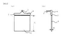
図1に示す、底面が正方形の四角柱状で、上面の対角線の交点を中心とした円を底面とする円錐の頂点側を、円錐の底面と平行に切り落とした形状のスプルー3を、該四角柱の上面に装着することにより形成されるインサート成形品1を、シリンダ温度260℃、金型温度80℃の条件で成形した。
【0050】
図1(a)は上記インサート成形品の平面図であり、(b)は同成形品の側面図である。
【0051】
インサート成形品1は金型にインサート金属4を装着し、射出成形機から樹脂を射出し、射出された樹脂をスプルー3から、インサート金属4を覆うように金型キャビティ内に充填し、樹脂2およびスプルー3を固化させることにより形成される。
【0052】
インサート金属を金型に装着し金属と金型が接触している部分には樹脂が流れ込まないため、インサート成形品1の底面には、その部分に相当する樹脂未充填部5ができる。
【0053】
インサート成形品1の、四角柱部分の底面(正方形)の辺の長さLは50mm、高さは30mm、そして樹脂2の厚みWは1.5mmである。
【0054】
該成形品を130℃環境下1時間処理後、−40℃環境下1時間処理を行い、再び130℃環境下に放置する冷熱サイクル処理を行い、成形品の外観を目視した。インサート成形品にクラックが発生したサイクル数を表中に記載し、その数値の大小を耐冷熱性の指標とした。
【0055】
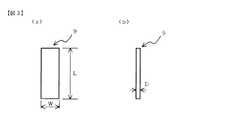
(7)レーザ光線透過性評価
試験片は図2のLが80mm正方形で、厚みDが3mmのレーザ光線透過性評価試験片8を用いた。その成形条件はシリンダ温度260℃、金型温度80℃である。図2(a)は、上記レーザ光線透過性評価試験片の平面図であり、(b)は同試験片の側面図である。
【0056】
レーザ光線透過性評価試験片8はスプルー3、ランナー6、ゲート7から切断し、レーザ光線透過性評価試験片として用いた。
【0057】
試験機は(株)島津製作所製の紫外近赤外分光高度計(UV−3100)を用い、また検出器には積分球を用いた。
【0058】
透過率は透過光量と入射光量の比を百分率で表す。表中には、近赤外線800〜1100nm波長領域の光線透過率を「透過性」として記載した。
【0059】
(8)レーザ溶着性評価
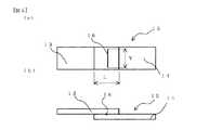
試験片は、図2のレーザ光線透過性評価試験片8と同形状のものと、前記成形品の厚さDのみが2mmと異なる2種類の成形品からそれぞれ切り出し加工してなる、幅Wが24mm、長さLが70mm、厚みDは3mmと2mmのレーザ溶着用試験片9試験片を用いた。図3(a)は上記加工後の試験片の平面図であり、(b)はその側面図である。
【0060】
レーザ溶着機は、ライスター社のMODULAS Cを用いた。該溶着機は半導体レーザ使用の機器であり、レーザ光の波長は940nmの近赤外線である。最大出力が35W、焦点距離Lが38mm、焦点径Dが0.6mmである。
【0061】
図4はレーザ溶着方法の概略を示す概略図である。
【0062】
レーザ溶着方法は図4に示すように、レーザ光線を透過させる材料を用いたレーザ溶着用試験片13を上部に、下部にはレーザ光線を吸収させる材料を用いたレーザ溶着用試験片14を置き、重ね合わせ、上部よりレーザ光線を照射する。レーザ照射はレーザ溶着軌道12に沿って行い、レーザ溶着条件は、出力15〜35W範囲および、レーザ走査速度1〜50mm/secの範囲で最も良好な溶着強度が得られる条件で行った。尚、焦点距離は38mm、焦点径は0.6mm固定で実施した。
【0063】
レーザ溶着の可否は「溶着可否」として記載し、レーザ溶着を行い溶着可能な条件において、レーザ光線透過試料の光線入射表面に溶融痕が認められる場合は「×」、溶融痕が認められず、溶着が可能な場合は「○」と記載した。尚、「溶着可否(3mmt)」項にはレーザ光線透過側試料に厚み3mmの試験片を用いた場合の溶着可否、「溶着可否(2mmt)」項においては、レーザ光線透過側試料に厚み2mmの試験片を用いた場合の溶着可否を記載した。
【0064】
図5(a)は上記方法でレーザ溶着したレーザ溶着強度測定用試験片の平面図であり、(b)は同試験片の側面図である。レーザ溶着強度測定用試験片15は図3に示したレーザ溶着試験片であるレーザ光線透過側試料13とレーザ光線吸収側試料14とが、重ね合わせ長さLを30mmとし、溶着距離Yは20mmとして、重ね合わせて溶着部16で溶着したものである。溶着強度測定には一般的な引張試験器(AG−500B)を用い、該試験片の両端を固定し、溶着部位には引張剪断応力が発生するように引張試験を行った。強度測定時の引張速度は1mm/min、スパンは40mmである。溶着強度は溶着部位が破断したときの応力とした。尚、レーザ光線透過試料へは本発明のポリブチレンテレフタレート系樹脂を用い、レーザ光線吸収側試料へは、ポリブチレンテレフタレート樹脂100重量部に対し、ガラス繊維を43重量部添加し、更にはカーボンブラックを0.4部添加した材料を用いた。
【0065】
以下に実施例および比較例に使用した配合組成物を示す。
【0066】
(1)PBT:ポリブチレンテレフタレート樹脂 固有粘度0.81dl/g。
【0067】
(2)PBT/I:ポリブチレンテレフタレート/イソフタレート共重合体
(a)組成:テレフタル酸/イソフタル酸:90/10mol%
(b)PBT/Iの製造方法
テレフタル酸(以下、TPAともいう)450部、イソフタル酸(以下、IPAともいう)50部[TPA/IPA=90/10mol%]、1,4−ブタンジオール407部、テトラ−n−ブチルチタネート1部を精留塔付き反応器に仕込み、500mmHgの減圧環境下で、180℃から230℃まで徐々に昇温してエステル化反応率95%以上にまで反応させ、次いで240℃、0.5mmHgにまで昇温、減圧して3時間30分後に重合を完結させた。得られた共重合体の固有粘度は0.80dl/gであった。
【0068】
(3)PC:ポリカーボネート樹脂(粘度平均分子量:19000)。
【0069】
(4)AS:アクリロニトリル−スチレン共重合体(アクリロニトリルとスチレンの共重合比:アクリロニトリル/スチレン=24/76(重量比)、固有粘度:0.60dl/g)。
【0070】
(5)タルク(結晶核剤):含水ケイ酸マグネシウム、見掛け比重=0.20g/cc、pH=9.3、平均粒子径=5.29μm。
【0071】
(6)GF:ガラス繊維(平均繊維径:13μm、繊維長3mmのチョップドストランド)。
【0072】
(7)エラストマ(スチレン系)
:スチレン−ブタジエンブロック共重合体エポキシ化物、ダイセル化学工業(株)製エポフレンドA1010(スチレンとブタジエンの共重合比:スチレン/ブタジエン=40/60(重量比)、エポキシ当量1000、MFR=7g/10min(測定法:JIS−K7210))。
【0073】
(8)エラストマ(エチレン系A)
:エチレン−グリシジルメタクリレート共重合体。両成分の共重合比(重量比)はエチレン単位/グリシジルメタクリレート単位=94/6(重量%)。MFR=3.2g/10min(測定法:JIS−K6760(190℃、2160g荷重))。
【0074】
(9)エラストマ(エチレン系B)
:エチレン・α−オレフィンコポリマー(エチレンと1−ブテンの共重合比:エチレン/1−ブテン=84/16(重量比)、MFR=3.6g/10min(測定法:JIS−K6760(190℃、2160g荷重)))。
【0075】
(10)エラストマ(エチレン系C)
:エチレン−メチルアクリレート−グリシジルメタクリレート共重合体。各成分の共重合比(重量比)はエチレン単位/メチルアクリレート単位/グリシジルメタクリレート単位=64/30/6(重量%)。MFR=9g/10min(測定法:JIS−K6760(190℃、2160g荷重))。
(11)エラストマ(エチレン系D)
:エチレン−エチルアクリレート共重合物。両成分の共重合比(重量比)はエチレン単位/エチルアクリレート単位=65/35(重量%)。MFR=25g/10min(測定法:JIS−K6760(190℃、2160g荷重))。
【0076】
参考例1〜7、比較例1〜9
参考例1〜7及び比較例1〜9に記載した材料の製造方法は次の通りである。すなわちシリンダ温度250℃に設定したスクリュー径57mm直径の2軸押出機を用いて製造した。(A)成分(ポリブチレンテレフタレート系樹脂)、(B)成分(ポリカーボネート樹脂、もしくはアクリロニトリル・スチレン共重合体)、並びにその他の添加剤は元込め部から、(C)成分(ガラス繊維)を添加配合する場合はサイドフィーダーから供給して溶融混練を行い、ダイスから吐出されたストランドを冷却バス内で冷却した後、ストランドカッターにてペレット化した。得られた各材料は、130℃の熱風乾燥機で3時間乾燥した後、前記評価方法記載の方法を用いて成形し、評価を行った。
【0077】
参考例1〜7及び比較例1〜9の配合処方と結果を表1に記載した。比較例1〜9で得られた樹脂組成物は成形性が悪いか、成形可能であってもレーザ光線透過率が低いため、3mm厚みのレーザ光線透過側試料を用いた場合に、該成形体のレーザ入射表面に溶融痕が発生する不具合が生じた。
【0078】
【表1】
実施例1〜2、比較例10〜18、参考例8〜12
実施例1〜2、比較例10〜18、参考例8〜12に記載した材料の製造方法は次の通りである。すなわちシリンダ温度250℃に設定したスクリュー径57mm直径の2軸押出機を用いて製造した。(A)成分(ポリブチレンテレフタレート系樹脂)、(B)成分(ポリカーボネート樹脂)、(D)成分(スチレン系エラストマ)もしくはエチレン系エラストマ、並びにその他の添加剤は元込め部から、(C)成分(ガラス繊維)をサイドフィーダーから供給して溶融混練を行い、ダイスから吐出されたストランドを冷却バス内で冷却した後、ストランドカッターにてペレット化した。得られた各材料は、130℃の熱風乾燥機で3時間乾燥した後、前記評価方法記載の方法を用いて成形し、評価を行った。
【0080】
実施例1〜2及び比較例10〜18、参考例8〜12の配合処方と結果を表2に記載した。実施例1〜2で得られた組成物に耐冷熱性、耐衝撃性を付与する目的で、スチレン−ブタジエンブロック共重合体を添加配合した場合において、耐冷熱性、耐衝撃性の向上と、レーザ溶着可能なレーザ光線透過性レベル保持を両立し、本発明で得られた樹脂組成物はいずれも3mm厚みの試料をレーザ光線透過側に用いた場合に、レーザ光線透過試料の光線入射表面に溶融痕が発生することなく、溶着することができた。一方、比較例10〜18で得られた樹脂組成物は成形性が悪いか、成形可能であってもレーザ光線透過率が低いため、3mm厚みのレーザ光線透過側試料を用いた場合に、該成形体のレーザ入射表面に溶融痕が発生する不具合が生じた。
【0081】
【表2】
【発明の効果】
上述したように、本発明のポリブチレンテレフタレート樹脂組成物は、レーザ光線透過性に優れたものであり、更には耐冷熱性、機械的強度にも優れる。この利点を活かして、各種用途の樹脂成形体のレーザ溶着接合に有用である。
【図面の簡単な説明】
【図1】(a)は実施例で耐冷熱性評価に用いたインサート成形品の平面図であり、(b)は同成形品の側面図である。
【図2】(a)は実施例で用いたレーザ光線透過性評価試験片のであり、(b)は同試験片の側面図である。
【図3】(a)は実施例で用いたレーザ溶着用試験片の平面図であり、(b)は同試験片の側面図である。
【図4】レーザ溶着方法の概略を示す概略図である。
【図5】(a)は実施例で用いたレーザ溶着強度測定試験片の平面図であり、(b)は同試験片の側面図である。
【符号の説明】
1.インサート成形品
2.樹脂
3.スプルー
4.インサート金属
5.樹脂未充填部
6.ランナー
7.ゲート
8.レーザ光線透過性評価試験片
9.レーザ溶着用試験片
10.レーザ光線照射部
11.レーザ光線
12.レーザ光の軌道
13.レーザ光線透過側試料
14.レーザ光線吸収側試料
15.レーザ溶着強度測定用試験片
16.レーザ溶着部[0001]
BACKGROUND OF THE INVENTION
The present invention relates to a resin composition for laser welding excellent in heat resistance, cooling performance, molded article surface appearance, dimensional stability, and laser weldability, and a composite molded article using the same, and further to other articles. The present invention relates to a polybutylene terephthalate resin composition suitable for a composite molded body obtained by laser welding and a composite molded body using the same.
[0002]
[Prior art]
Polybutylene terephthalate resin uses its excellent injection moldability, mechanical properties, heat resistance, electrical properties, chemical resistance, etc. to make a wide range of injection molded products in the fields of mechanical parts, electrical / communication parts, automotive parts, etc. Has been used. However, although the molding efficiency of the injection molded product is good, the shape is limited in terms of its flow characteristics and mold structure, and it is difficult to mold a complicated one.
[0003]
Conventionally, in joining parts due to the complexity of product shape, joining with an adhesive, mechanical joining with a bolt or the like has been performed. However, adhesives have problems of adhesive strength, and mechanical joining with bolts and the like has problems of cost, labor for fastening, and weight increase. On the other hand, external heat welding such as laser welding and hot plate welding, frictional heat welding such as vibration welding and ultrasonic welding can be performed in a short time, and no adhesive or metal parts are used. Since problems such as cost, weight increase and environmental pollution do not occur, assembly by these methods is increasing.
[0004]
Laser welding, one of the external heating welding methods, is a method of irradiating a laser beam onto the superimposed resin moldings, allowing the irradiated one to pass through, absorbing the other, melting, and fusing, enabling three-dimensional bonding It is a method that is spreading in a wide range of fields, taking advantage of non-contact processing and the absence of burrs.
[0005]
In this construction method, in the resin material applied to the laser beam transmission side molded body, the characteristic of transmitting the laser beam is essential, and when the energy of the irradiated laser beam is 100%, the back side of the laser beam transmission side molded body From the examination results of the present inventors, it has been found that the energy that permeates through and needs to be 10% or more. When a molded product having a laser beam transmittance of less than 10% is used as the molded product on the laser beam transmission side, there is a sufficient possibility that defects such as melting and smoke generation may occur on the laser beam incident surface.
[0006]
The polybutylene terephthalate resin used in many applications has a very low laser beam transmittance compared to nylon resins and other thermoplastic resins. Polybutylene terephthalate resin is used as a molded product on the laser beam transmission side. When applying the laser welding method, the thickness limit is very strict due to its low laser beam transmittance, and it is necessary to cope with the thinning to improve the laser beam transmittance, and the degree of freedom in product design is small. It was.
[0007]
[0008]
[Patent Document 1]
JP 2001-26656 A (paragraphs [0008] to [0024])
[0009]
[Problems to be solved by the invention]
The present invention eliminates the above-mentioned conventional problems, and even in a polybutylene terephthalate-based resin, it can be applied as a laser beam transmission side molded body without lowering the product design flexibility. An object of the present invention is to provide a resin composition.
[0010]
[Means for Solving the Problems]
In order to solve the above problems, the present invention has the following configuration. (1) (A) polybutylene terephthalate or polybutylene terephthalate resin comprising polybutylene terephthalate and polybutylene terephthalate copolymer, and (B) polycarbonate resin, acrylonitrile / styrene copolymer, polyphenylene oxide, styrene resin , At least one resin selected from acrylic resin, polyethersulfone, polyarylate, polyethylene terephthalate resin, and (C) at least one filler selected from inorganic fillers and organic fillers; D) A styrene-butadiene block copolymer is blended, and (B) is 1 to 50% by weight based on the total of (A) and (B), and (C) is (A) and (B). 1 to 200 parts by weight with respect to a total amount of 100 parts by weight, and (D) is (A), ( The total amount 100 parts by weight of), the laser welding for a resin composition is 1 to 50 parts by weightA laser welding resin composition having a welding strength of 36 MPa or more when a 2 mm thick sample is used on the laser beam transmitting side..
(2) The laser welding resin according to (1), wherein (D) the styrene-butadiene block copolymer has a light transmittance higher than the light transmittance in the same wavelength region of polybutylene terephthalate in the wavelength region of 400 to 1100 nm. Composition.
(3) A composite molded body obtained by laser welding a molded product made of the laser welding resin composition according to (1) or (2).
[0011]
DETAILED DESCRIPTION OF THE INVENTION
Embodiments of the present invention will be described below.
[0012]
In the present invention, the (A) polybutylene terephthalate resin (hereinafter also referred to as the component (A)) may be the polybutylene terephthalate alone, or a combined use of polybutylene terephthalate and a polybutylene terephthalate copolymer. It may be.
[0013]
The polybutylene terephthalate used in the present invention is a polymer obtained by polycondensation reaction of terephthalic acid (or its ester-forming derivative such as dimethyl terephthalate) and 1,4-butanediol (or its ester-forming derivative). It is.
[0014]
The polybutylene terephthalate copolymer that can be used in combination with the polybutylene terephthalate includes terephthalic acid (or an ester-forming derivative such as dimethyl terephthalate) and 1,4-butanediol (or an ester-forming derivative thereof). ) And other dicarboxylic acids copolymerizable therewith (or ester-forming derivatives thereof) or other diols (or ester-forming derivatives thereof), and other dicarboxylic acids as the third component. A copolymer obtained by copolymerizing an acid (or an ester-forming derivative thereof) is preferable.
[0015]
The copolymerization ratio of the other dicarboxylic acid (or its ester-forming derivative) is preferably in the range of 3 to 30 mol% in the total dicarboxylic acid component from the viewpoint of moldability, and in the range of 3 to 20 mol%. More preferably.
[0016]
In addition, the copolymerization ratio of other diols (or ester-forming derivatives thereof) is preferably in the range of 3 to 30 mol% in the total diol component from the viewpoint of moldability, and in the range of 3 to 20 mol%. More preferably.
[0017]
Examples of the other dicarboxylic acids include isophthalic acid, phthalic acid, 2,6-naphthalenedicarboxylic acid, 1,5-naphthalenedicarboxylic acid, bis (p-carboxyphenyl) methane, anthracene dicarboxylic acid, and 4,4′-diphenyl ether dicarboxylic acid. Acids, aromatic dicarboxylic acids such as 5-sodiumsulfoisophthalic acid, aromatic dicarboxylic acids such as adipic acid, sebacic acid, azelaic acid, dodecanedioic acid, 1,3-cyclohexanedicarboxylic acid, 1,4-cyclohexanedicarboxylic acid, etc. And alicyclic dicarboxylic acid.
[0018]
When only the polybutylene terephthalate copolymer is used as the component (A), from among polycarbonate resin, acrylonitrile / styrene copolymer, polyphenylene oxide, styrene resin, acrylic resin, polyethersulfone, polyarylate, polyethylene terephthalate resin Since at least one selected additive deteriorates moldability, it is not preferable.
[0019]
The viscosity of the component (A) is not particularly limited as long as it can be melt-kneaded. However, it is usually preferable that the intrinsic viscosity when an o-chlorophenol solution is measured at 25 ° C. is 0.36 to 1.60. . When component (A) is composed of polybutylene terephthalate and polybutylene terephthalate copolymer, the physical or molten mixture is dissolved in o-chlorophenol after pulverization or in the form of pellets, and o-chloro The result of adjusting the phenol solution and measuring the viscosity only has to be within the viscosity condition.
[0020]
In the present invention, at least one selected from (B) polycarbonate resin, acrylonitrile / styrene copolymer, polyphenylene oxide, styrene resin, acrylic resin, polyethersulfone, polyarylate, and polyethylene terephthalate resin together with the component (A). In order to obtain a composition excellent in laser beam transmittance, it is preferable to use a polycarbonate resin.
[0021]
The blending amount of the component (B) with respect to the total of (A) and (B) is 1 to 50% by weight, preferably 5 to 40% by weight, from the viewpoint of an improvement in laser beam transmittance. When the blending amount of the component (B) is less than 1% by weight, the laser beam transmittance is insufficient, and when it exceeds 50% by weight, the moldability and the high-temperature rigidity are lowered, which is not preferable.
[0022]
In the present invention, (C) inorganic and organic fillers (hereinafter also referred to as (C) component) are further blended..Component (C) is a fiber such as glass fiber, carbon fiber, potassium titanate whisker, zinc oxide whisker, aluminum borate whisker, aramid fiber, alumina fiber, silicon carbide fiber, ceramic fiber, asbestos fiber, gypsum fiber, or metal fiber. Reinforcing materials, wollastonite, zeolite, sericite, kaolin, mica, clay, pyrofilament, bentonite, asbestos, talc, alumina silicate and other silicates, alumina, silicon oxide, magnesium oxide, zirconium oxide, titanium oxide, iron oxide, etc. Metal compounds, carbonates such as calcium carbide, magnesium carbonate and dolomite, sulfates such as calcium sulfate and barium sulfate, glass beads, ceramic beads, boron nitride, silicon carbide and non-fibrous reinforcing materials such as silica and the like. As a preferable example, Las fiber and the like.
[0023]
Furthermore, it is more preferable to use these fillers after being pretreated with a coupling agent such as silane, epoxy, or titanate.
[0024]
The addition amount of the component (C) used in the present invention is 1 to 200 parts by weight with respect to 100 parts by weight of the total amount of the component (A) and the component (B) from the balance between fluidity and
[0025]
In the present invention, impact resistance and cold / heat resistance can be imparted by further blending an elastomer with the components (A) and (B). As such an elastomer,Styrene-butadiene block copolymer(The addition amount of the elastomer is 1 to 50 parts by weight with respect to 100 parts by weight of the total amount of the components (A) and (B).It is. (While sufficiently retaining the high laser beam transmittance of the component (A) and the component (B), it is possible to further impart impact resistance and cold resistance. Here, the resistance to cold and heat is a resin molded body formed by insert molding of metal or the like, which is greatly different from polybutylene terephthalate resin, etc., and has resistance to cracking in repeated environments at low and high temperatures. To tell.
[0026]
As said (D) component, it has a light transmittance higher than the light transmittance in the same wavelength area | region of a polybutylene terephthalate in a 400-1100 nm wavelength area | region.Styrene-butadiene block copolymerUsingThe As a styrene-butadiene block copolymer, it is preferable.A styrene-butadiene block copolymer epoxidized product is preferable. As an epoxidized product of this styrene-butadiene block copolymer, Epofriend A1010 manufactured by Daicel Chemical Industries, Ltd. can be used.
[0027]
The addition amount of the component (D) used in the present invention is 1 to 50 parts by weight with respect to 100 parts by weight of the total amount of the component (A) and the component (B), from the balance of laser beam transmittance, moldability and cold resistance. In the range of 2 to 20 parts by weightPreferGood. If the addition amount is less than 1 part by weight, there is almost no effect of impact resistance and cold heat resistance due to the addition of component (D), and if it exceeds 50 parts by weight, the moldability, particularly the fluidity, is not preferred.
[0028]
The polybutylene terephthalate resin composition of the present invention includes a release agent, an antioxidant, a stabilizer, a lubricant, a crystal nucleating agent, a terminal blocker, an ultraviolet absorber, and a colorant as long as the effects of the present invention are not impaired. Normal additives such as flame retardants and small amounts of other polymers can be added, but especially by adding a crystal nucleating agent, the crystallization rate (solidification rate) is increased and the molding cycle is shortened. It is possible.
[0029]
Examples of mold release agents include montanic acid waxes, metal soaps such as lithium stearate and aluminum stearate, higher fatty acid amides such as ethylene bisstearyl amide, and ethylenediamine / stearic acid / sebacic acid polycondensates. Among them, montanic acid waxes and ethylene bisstearylamide are preferable.
[0030]
Examples of antioxidants include 2,6-di-t-butyl-4-methylphenol, tetrakis (methylene-3- (3,5-di-t-butyl-4-hydroxyphenyl) propionate) methane, tris Phenol compounds such as (3,5-di-t-butyl-4-hydroxybenzidine) isocyanurate, sulfur such as dilauryl-3,3′-thiodipropionate, dimyristyl-3,3′-thiodipropionate Examples thereof include phosphorus compounds such as compounds, trisnonylphenyl phosphite, disaryl pentaerythritol diphosphite, among others, 2,6-di-t-butyl-4-methylphenol, tetrakis (methylene-3- (3,5-di-tert-butyl-4-hydroxyphenyl) propionate) methane is preferred.
[0031]
Examples of stabilizers include benzotriazole-based compounds including 2- (2′-hydroxy-5′-methylphenyl) benzotriazole, as well as benzophenone-based compounds such as 2,4-dihydroxybenzophenone, mono- or distearyl phosphate, Examples thereof include phosphate esters such as trimethyl phosphate.
[0032]
Examples of the crystal nucleating agent include polyetheretherketone resin and talc. By adding these crystal nucleating agents, the crystallization speed (solidification speed) is increased and the molding cycle can be shortened.
[0033]
Examples of the end-capping agent include aliphatic and aromatic glycidyl esters or glycidyl ethers.
[0034]
These various additives may have a synergistic effect by combining two or more kinds, and may be used in combination.
[0035]
For example, the additive exemplified as the antioxidant may act as a stabilizer or an ultraviolet absorber. Some of those exemplified as stabilizers also have an antioxidant action and an ultraviolet absorption action. That is, the above classification is for convenience and is not a thing with limited action.
[0036]
What is necessary is just to implement about the manufacturing method of the polybutylene terephthalate-type resin composition of this invention by the method generally known, and it does not need to specifically limit. Typical examples include a melt kneading method at a temperature of 200 to 350 ° C. using a known melt mixer such as a single or twin screw extruder, a Banbury mixer, a kneader, or a mixing roll. Each component may be mixed in advance and then melt kneaded. Alternatively, for 100 parts by weight of the total amount of the components (A) to (D), for a small amount of additive component such as 1 part by weight or less, after kneading and pelletizing the other components by the above method, etc. It can also be added before molding. In addition, although it is better that the water | moisture content adhering to each component is less and it is desirable to dry beforehand, not all the components need to be dried.
[0037]
As an example of a preferable production method, a twin screw extruder having a cylinder temperature of 230 to 300 ° C. is used, and components other than the component (C) are supplied and kneaded from the upstream side of the extruder, and then the component (C) is side-feeded. Furthermore, the method of kneading is mentioned.
[0038]
The resin composition of the present invention is generally molded by a known thermoplastic resin molding method such as injection molding, extrusion molding, blow molding, transfer molding, vacuum molding, etc., among which injection molding is preferable.
[0039]
The polybutylene terephthalate-based resin composition of the present invention is used as a material to be subjected to laser welding by making use of its excellent characteristics, but is suitable for a laser beam transmission side molded body of a laser welding method, and the composition By adding a near-infrared absorbent such as carbon black to the product, it can be easily applied to a molded article on the laser beam absorption side.
[0040]
The polybutylene terephthalate resin composition of the present invention can further impart cold resistance, mechanical strength, and the like by adding a filler or an elastomer in addition to the laser beam transparency. Taking advantage of this advantage, it is useful for laser welding and bonding, particularly for laser beam transmission side moldings of resin moldings for various uses.
[0041]
【Example】
Examples Hereinafter, the present invention will be described more specifically with reference to examples. However, the present invention is not limited to the description of these examples. Moreover, all the addition mixture ratios shown in Examples and Comparative Examples are parts by weight.
[0042]
The material property evaluation method of an Example and a comparative example is shown below.
[0043]
(1) Formability evaluation
Using a general injection molding machine (Nissei 60E9ASE), when molding a tensile specimen (
[0044]
Since the test piece for carrying out the other characteristic evaluation was difficult for the thing of "x" display, subsequent evaluation was not able to be performed. These are indicated by “−” in the characteristic section of the table.
[0045]
(2) Tensile strength
Evaluation was performed by a method based on ASTM D638. The test piece is an ASTM No. 1 type (thickness 3.2 mm), and the molding conditions are a cylinder temperature of 260 ° C. and a mold temperature of 80 ° C.
[0046]
(3) Flexural modulus
Evaluation was performed by a method based on ASTM D790. A specimen having a thickness of 3.2 mm is used, and the molding conditions are a cylinder temperature of 260 ° C. and a mold temperature of 80 ° C.
[0047]
(4) Impact strength
Evaluation was performed by a method based on ASTM D256. The test piece has a width of 3.2 mm and uses a notched test piece. The molding conditions are a cylinder temperature of 260 ° C. and a mold temperature of 80 ° C.
[0048]
(5) Deflection temperature under load
Evaluation was performed by a method based on ASTM D648. The applied stress is 1.82 MPa. A specimen having a thickness of 6.4 mm is used, and the molding conditions are a cylinder temperature of 260 ° C. and a mold temperature of 80 ° C.
[0049]
(6) Evaluation of heat resistance
As shown in FIG. 1, a
[0050]
Fig.1 (a) is a top view of the said insert molded product, (b) is a side view of the molded product.
[0051]
The insert molded
[0052]
Since the resin does not flow into the portion where the insert metal is mounted on the mold and the metal and the mold are in contact with each other, the resin
[0053]
The length L of the side of the bottom (square) of the quadrangular prism portion of the insert molded
[0054]
The molded product was treated in an environment of 130 ° C. for 1 hour, then treated in an environment of −40 ° C. for 1 hour, and then subjected to a thermal cycle treatment in which the molded product was left in an environment of 130 ° C., and the appearance of the molded product was visually observed. The number of cycles in which cracks occurred in the insert-molded product was shown in the table, and the magnitude of the value was used as an index for cold resistance.
[0055]
(7) Laser beam transmission evaluation
The test piece used was a laser beam transmission evaluation test piece 8 having a square L of 80 mm and a thickness D of 3 mm in FIG. The molding conditions are a cylinder temperature of 260 ° C. and a mold temperature of 80 ° C. Fig.2 (a) is a top view of the said laser beam transmittance | permeability evaluation test piece, (b) is a side view of the test piece.
[0056]
The laser beam transmission evaluation test piece 8 was cut from the
[0057]
The tester used was an ultraviolet near infrared spectrophotometer (UV-3100) manufactured by Shimadzu Corporation, and an integrating sphere was used as the detector.
[0058]
The transmittance represents the ratio between the transmitted light amount and the incident light amount as a percentage. In the table, the light transmittance in the near-infrared 800 to 1100 nm wavelength region is described as “transmittance”.
[0059]
(8) Laser weldability evaluation
The test piece has the same shape as the laser beam transmission evaluation test piece 8 of FIG. 2 and a width W formed by cutting out from two types of molded products in which only the thickness D of the molded product is different from 2 mm.
[0060]
As the laser welding machine, MODULAS C manufactured by Leister Co., Ltd. was used. The welding machine is a device using a semiconductor laser, and the wavelength of the laser beam is near infrared at 940 nm. The maximum output is 35 W, the focal length L is 38 mm, and the focal diameter D is 0.6 mm.
[0061]
FIG. 4 is a schematic view showing an outline of the laser welding method.
[0062]
As shown in FIG. 4, a laser welding test piece 13 using a material that transmits a laser beam is placed in the upper part, and a laser welding test piece 14 that uses a material that absorbs the laser beam is placed in the lower part. , Superimpose and irradiate laser beam from the top. Laser irradiation was performed along the laser welding trajectory 12, and the laser welding conditions were performed under conditions where the best welding strength was obtained in the output 15 to 35 W range and the
[0063]
Whether laser welding is possible or not is described as “welding feasibility”, and in the condition where laser welding can be performed and welding is possible, “X” when a melting mark is observed on the light incident surface of the laser beam transmitting sample, no melting mark is recognized, When welding was possible, it was described as “◯”. In the “weldability (3 mmt)” section, whether or not a 3 mm thick test piece is used for the laser beam transmission side sample, and in the “weldability (2 mmt)” section, the laser beam transmission side sample has a thickness of 2 mm. Whether or not the test piece was welded was described.
[0064]
FIG. 5A is a plan view of a test piece for laser welding strength measurement laser-welded by the above method, and FIG. 5B is a side view of the test piece. The laser welding strength measurement test piece 15 is a laser welding test piece shown in FIG. 3, and the laser beam transmission side sample 13 and the laser beam absorption side sample 14 have an overlap length L of 30 mm and a welding distance Y of 20 mm. As shown in FIG. A general tensile tester (AG-500B) was used to measure the welding strength, and both ends of the test piece were fixed, and a tensile test was performed so that a tensile shear stress was generated at the welding site. The tensile speed during strength measurement is 1 mm / min, and the span is 40 mm. The welding strength was the stress when the welded site was broken. In addition, the polybutylene terephthalate resin of the present invention is used for the laser beam transmission sample, and 43 parts by weight of glass fiber is added to the laser beam absorption side sample with respect to 100 parts by weight of the polybutylene terephthalate resin. The material which added 0.4 part of was used.
[0065]
The compounding composition used for the Example and the comparative example below is shown.
[0066]
(1) PBT: polybutylene terephthalate resin Intrinsic viscosity 0.81 dl / g.
[0067]
(2) PBT / I: polybutylene terephthalate / isophthalate copolymer
(A) Composition: terephthalic acid / isophthalic acid: 90/10 mol%
(B) PBT / I manufacturing method
450 parts of terephthalic acid (hereinafter also referred to as TPA), 50 parts of isophthalic acid (hereinafter also referred to as IPA) [TPA / IPA = 90/10 mol%], 407 parts of 1,4-butanediol, tetra-n-
[0068]
(3) PC: Polycarbonate resin (viscosity average molecular weight: 19000).
[0069]
(4) AS: Acrylonitrile-styrene copolymer (copolymerization ratio of acrylonitrile and styrene: acrylonitrile / styrene = 24/76 (weight ratio), intrinsic viscosity: 0.60 dl / g).
[0070]
(5) Talc (crystal nucleating agent): hydrous magnesium silicate, apparent specific gravity = 0.20 g / cc, pH = 9.3, average particle size = 5.29 μm.
[0071]
(6) GF: Glass fiber (average fiber diameter: 13 μm, chopped strand having a fiber length of 3 mm).
[0072]
(7) Elastomer (styrene)
: Styrene-butadiene block copolymer epoxidized product, Epofriend A1010 manufactured by Daicel Chemical Industries, Ltd. (copolymerization ratio of styrene and butadiene: styrene / butadiene = 40/60 (weight ratio), epoxy equivalent 1000, MFR = 7 g / 10 min (measurement method: JIS-K7210)).
[0073]
(8) Elastomer (Ethylene-based A)
: Ethylene-glycidyl methacrylate copolymer. The copolymerization ratio (weight ratio) of both components is ethylene unit / glycidyl methacrylate unit = 94/6 (% by weight). MFR = 3.2 g / 10 min (measurement method: JIS-K6760 (190 ° C., 2160 g load)).
[0074]
(9) Elastomer (Ethylene B)
: Ethylene / α-olefin copolymer (copolymerization ratio of ethylene and 1-butene: ethylene / 1-butene = 84/16 (weight ratio), MFR = 3.6 g / 10 min (measurement method: JIS-K6760 (190 ° C., 2160 g load))).
[0075]
(10) Elastomer (ethylene-based C)
: Ethylene-methyl acrylate-glycidyl methacrylate copolymer. The copolymerization ratio (weight ratio) of each component is ethylene unit / methyl acrylate unit / glycidyl methacrylate unit = 64/30/6 (% by weight). MFR = 9 g / 10 min (Measurement method: JIS-K6760 (190 ° C., 2160 g load)).
(11) Elastomer (Ethylene-based D)
: Ethylene-ethyl acrylate copolymer. The copolymerization ratio (weight ratio) of both components is ethylene unit / ethyl acrylate unit = 65/35 (% by weight). MFR = 25 g / 10 min (measurement method: JIS-K6760 (190 ° C., 2160 g load)).
[0076]
Reference example1-7, Comparative Examples 1-9
Reference exampleThe manufacturing method of the material described in 1-7 and Comparative Examples 1-9 is as follows. That is, it was manufactured using a twin screw extruder having a screw diameter of 57 mm set at a cylinder temperature of 250 ° C. Component (A) (polybutylene terephthalate-based resin), component (B) (polycarbonate resin or acrylonitrile / styrene copolymer), and other additives are added from the original loading part (C) component (glass fiber) In the case of blending, the mixture was supplied from the side feeder, melted and kneaded, the strand discharged from the die was cooled in a cooling bath, and then pelletized with a strand cutter. Each obtained material was dried for 3 hours with a hot air dryer at 130 ° C., and then molded and evaluated using the method described in the evaluation method.
[0077]
Reference exampleThe formulation and results of 1 to 7 and Comparative Examples 1 to 9 are shown in Table 1.. ratioThe resin compositions obtained in Comparative Examples 1 to 9 have poor moldability or have low laser beam transmittance even if moldable, so when a 3 mm-thick laser beam transmission side sample is used, the molded product There was a problem that melting marks were generated on the laser incident surface.
[0078]
[Table 1]
Example1-2Comparative Examples 10-18Reference Examples 8-12
Example1-2Comparative Examples 10-18Reference Examples 8-12The manufacturing method of the material described in 1 is as follows. That is, it was manufactured using a twin screw extruder having a screw diameter of 57 mm set at a cylinder temperature of 250 ° C. Component (A) (polybutylene terephthalate-based resin), component (B) (polycarbonate resin), component (D) (styrene-based elastomer) or ethylene-based elastomer, and other additives are added from the original loading part, component (C) (Glass fiber) was supplied from the side feeder, melted and kneaded, and the strand discharged from the die was cooled in a cooling bath, and then pelletized with a strand cutter. Each obtained material was dried for 3 hours with a hot air dryer at 130 ° C., and then molded and evaluated using the method described in the evaluation method.
[0080]
Example1-2And Comparative Examples 10-18Reference Examples 8-
[0081]
[Table 2]
【The invention's effect】
As described above, the polybutylene terephthalate resin composition of the present invention is excellent in laser beam transmission, and is also excellent in cold resistance and mechanical strength. Taking advantage of this advantage, it is useful for laser welding joining of resin molded bodies for various uses.
[Brief description of the drawings]
FIG. 1A is a plan view of an insert molded product used for evaluation of heat resistance in an example, and FIG. 1B is a side view of the molded product.
FIG. 2 (a) is a laser beam transmission evaluation test piece used in the example, and FIG. 2 (b) is a side view of the test piece.
3A is a plan view of a laser welding test piece used in Examples, and FIG. 3B is a side view of the test piece.
FIG. 4 is a schematic view showing an outline of a laser welding method.
FIG. 5A is a plan view of a laser welding strength measurement test piece used in Examples, and FIG. 5B is a side view of the test piece.
[Explanation of symbols]
1. Insert molded product
2. resin
3. Sprue
4). Insert metal
5. Resin unfilled part
6). runner
7). Gate
8). Laser beam transmission evaluation test piece
9. Laser welding specimen
10. Laser beam irradiation unit
11. Laser beam
12 Laser beam trajectory
13. Laser beam transmission side sample
14 Laser beam absorption side sample
15. Test piece for laser welding strength measurement
16. Laser welding part
Claims (3)
Translated fromJapanesePriority Applications (1)
| Application Number | Priority Date | Filing Date | Title |
|---|---|---|---|
| JP2003015473AJP4911548B2 (en) | 2002-01-29 | 2003-01-24 | Laser welding resin composition and composite molded body using the same |
Applications Claiming Priority (4)
| Application Number | Priority Date | Filing Date | Title |
|---|---|---|---|
| JP2002-20792 | 2002-01-29 | ||
| JP2002020792 | 2002-01-29 | ||
| JP2002020792 | 2002-01-29 | ||
| JP2003015473AJP4911548B2 (en) | 2002-01-29 | 2003-01-24 | Laser welding resin composition and composite molded body using the same |
Publications (2)
| Publication Number | Publication Date |
|---|---|
| JP2003292752A JP2003292752A (en) | 2003-10-15 |
| JP4911548B2true JP4911548B2 (en) | 2012-04-04 |
Family
ID=29253320
Family Applications (1)
| Application Number | Title | Priority Date | Filing Date |
|---|---|---|---|
| JP2003015473AExpired - LifetimeJP4911548B2 (en) | 2002-01-29 | 2003-01-24 | Laser welding resin composition and composite molded body using the same |
Country Status (1)
| Country | Link |
|---|---|
| JP (1) | JP4911548B2 (en) |
Families Citing this family (29)
| Publication number | Priority date | Publication date | Assignee | Title |
|---|---|---|---|---|
| WO2003085046A1 (en)* | 2002-04-08 | 2003-10-16 | Win Tech Polymer Ltd. | Polybutylene terephthalate resin composition for fusion bonding with laser and molded article |
| JP4589234B2 (en) | 2003-10-07 | 2010-12-01 | ウィンテックポリマー株式会社 | Laser welding resin composition and molded product |
| JP4720149B2 (en)* | 2003-12-02 | 2011-07-13 | 東レ株式会社 | Laser-welded colored resin composition and composite molded body using the same |
| US20050167025A1 (en)* | 2004-01-06 | 2005-08-04 | Toshikazu Kobayashi | Process for laser welding polyester compositions |
| JP5076270B2 (en)* | 2004-05-28 | 2012-11-21 | 東レ株式会社 | Hollow molded products and composite molded products |
| US7385013B2 (en) | 2004-05-12 | 2008-06-10 | Toray Industries, Inc. | Polymer alloy, thermoplastic resin composition, and molded article |
| JP2006312303A (en)* | 2004-10-01 | 2006-11-16 | Daicel Polymer Ltd | Laser beam welding resin composition and composite molding |
| JP2006188553A (en)* | 2004-12-28 | 2006-07-20 | Daicel Polymer Ltd | Laser welding resin composition and molded product |
| JP4685439B2 (en)* | 2004-12-28 | 2011-05-18 | ダイセルポリマー株式会社 | Laser welding resin composition and molded body |
| JP4854213B2 (en)* | 2005-04-13 | 2012-01-18 | ウィンテックポリマー株式会社 | Laser welding resin composition and molded product |
| JP4781030B2 (en)* | 2005-07-19 | 2011-09-28 | 旭化成イーマテリアルズ株式会社 | Method for producing resin composition |
| JP5034217B2 (en)* | 2005-11-09 | 2012-09-26 | 東レ株式会社 | Laser welding resin composition and composite molded body using the same |
| JP2007186584A (en)* | 2006-01-13 | 2007-07-26 | Mitsubishi Engineering Plastics Corp | Laser-welded polyester resin composition and molded article using the same |
| WO2008001790A1 (en) | 2006-06-30 | 2008-01-03 | Toray Industries, Inc. | Thermoplastic resin composition and molded article thereof |
| JP5034773B2 (en)* | 2006-08-22 | 2012-09-26 | 三菱エンジニアリングプラスチックス株式会社 | Manufacturing method of composite molded article including process of welding using laser beam and composite molded article |
| CN101501134B (en) | 2006-09-13 | 2012-02-22 | 胜技高分子株式会社 | Resin composition for laser welding and molded article |
| JP5085928B2 (en) | 2006-12-22 | 2012-11-28 | ウィンテックポリマー株式会社 | Laser welding resin composition and molded article |
| JP5332323B2 (en)* | 2007-06-07 | 2013-11-06 | 東レ株式会社 | Laser welding thermoplastic resin composition, molded article and composite molded body comprising the same |
| JP5223254B2 (en)* | 2007-07-12 | 2013-06-26 | 三菱エンジニアリングプラスチックス株式会社 | Laser welding polyester resin composition and molded article using the same |
| JP5879593B2 (en)* | 2012-01-30 | 2016-03-08 | オリヱント化学工業株式会社 | Laser welding resin composition and welded body thereof |
| WO2014126547A1 (en) | 2013-02-12 | 2014-08-21 | Hewlett-Packard Development Company, L.P. | Polyethylene terephthelate part bonded to polyester and polycarbonate alloy part |
| JP2014177117A (en)* | 2013-02-14 | 2014-09-25 | Toray Ind Inc | Fiber-reinforced thermoplastic resin molding, and production method thereof |
| JP6101791B2 (en)* | 2013-04-26 | 2017-03-22 | 日立オートモティブシステムズ株式会社 | Flow rate sensor, resin structure manufacturing method and determination method |
| CN106459568B (en) | 2014-06-05 | 2019-04-19 | Sabic环球技术有限责任公司 | Thermoplastic compositions and laser welded articles |
| US10781308B2 (en) | 2016-02-25 | 2020-09-22 | Mitsubishi Engineering-Plastics Corporation | Resin composition for laser welding and welded body thereof |
| EP3287493A1 (en)* | 2016-08-26 | 2018-02-28 | LANXESS Deutschland GmbH | Polyester compounds |
| US11390037B2 (en) | 2017-10-31 | 2022-07-19 | Mitsubishi Engineering-Plastics Corporation | Laser welded body |
| EP3957680A1 (en)* | 2020-08-17 | 2022-02-23 | SHPP Global Technologies B.V. | Compositions and articles of wave transmission and improved dimensional stability, radar cover material |
| JP7444336B1 (en)* | 2022-07-04 | 2024-03-06 | 東レ株式会社 | Thermoplastic polyester resin composition and molded products using the same |
- 2003
- 2003-01-24JPJP2003015473Apatent/JP4911548B2/ennot_activeExpired - Lifetime
Also Published As
| Publication number | Publication date |
|---|---|
| JP2003292752A (en) | 2003-10-15 |
Similar Documents
| Publication | Publication Date | Title |
|---|---|---|
| JP4911548B2 (en) | Laser welding resin composition and composite molded body using the same | |
| JP5245265B2 (en) | Laser-welded polyester resin composition and composite molded body | |
| CN100398604C (en) | Colored resin composition for laser welding and composite molded article using same | |
| JP5788790B2 (en) | Welded polybutylene terephthalate resin composition and composite molded article | |
| JP2008163167A (en) | Modified polyester resin composition for laser welding and composite molded body using the same | |
| JP3876141B2 (en) | Polyester resin composition and molded article thereof | |
| CN112469781B (en) | Polybutylene terephthalate resin composition | |
| WO2021225154A1 (en) | Resin composition, molded product, kit, vehicle on-board camera component, vehicle on-board camera module, and molded product manufacturing method | |
| JP4720149B2 (en) | Laser-welded colored resin composition and composite molded body using the same | |
| JP5034217B2 (en) | Laser welding resin composition and composite molded body using the same | |
| JP2005537160A (en) | Method of laser welding poly (ethylene terephthalate) | |
| WO2021225153A1 (en) | Galvano-type laser welding resin composition, molded article, galvano-type laser welding kit, onboard camera component, onboard camera module, uv ray exposure body, and method for manufacturing molded article | |
| JP2010070626A (en) | Polyester resin composition and composite molded article | |
| KR102189455B1 (en) | White-colored opaque laser weldable thermoplastic composition with excellent thermal dimensional stability | |
| BR112013021900B1 (en) | uses of thermoplastic molded part compositions and transparent laser molded parts, process for producing welded molded parts, and welded molded part | |
| JP4492522B2 (en) | Resin composition for laser marking and molded product using the same | |
| JP2006257338A (en) | Resin composition for laser welding and compound molded product | |
| JP2007517700A (en) | Method for laser welding polyester compositions | |
| JP2007320995A (en) | Resin composition for laser welding and molded article produced by using the same | |
| JP7447408B2 (en) | Polybutylene terephthalate resin composition for laser welding | |
| JP2007517966A (en) | Laser weldable polyester composition and method for laser welding | |
| JP4633532B2 (en) | Airtight switch parts | |
| JP2006273992A (en) | Resin composition for welding and method for welding resin | |
| JP2020180202A (en) | Laser welding polybutylene terephthalate resin composition | |
| CN114269851B (en) | Resin composition for laser transmission |
Legal Events
| Date | Code | Title | Description |
|---|---|---|---|
| A621 | Written request for application examination | Free format text:JAPANESE INTERMEDIATE CODE: A621 Effective date:20050909 | |
| A977 | Report on retrieval | Free format text:JAPANESE INTERMEDIATE CODE: A971007 Effective date:20071029 | |
| A131 | Notification of reasons for refusal | Free format text:JAPANESE INTERMEDIATE CODE: A131 Effective date:20080722 | |
| A521 | Request for written amendment filed | Free format text:JAPANESE INTERMEDIATE CODE: A523 Effective date:20080912 | |
| A02 | Decision of refusal | Free format text:JAPANESE INTERMEDIATE CODE: A02 Effective date:20081104 | |
| A521 | Request for written amendment filed | Free format text:JAPANESE INTERMEDIATE CODE: A523 Effective date:20081215 | |
| A911 | Transfer to examiner for re-examination before appeal (zenchi) | Free format text:JAPANESE INTERMEDIATE CODE: A911 Effective date:20090302 | |
| A912 | Re-examination (zenchi) completed and case transferred to appeal board | Free format text:JAPANESE INTERMEDIATE CODE: A912 Effective date:20090501 | |
| A01 | Written decision to grant a patent or to grant a registration (utility model) | Free format text:JAPANESE INTERMEDIATE CODE: A01 | |
| A61 | First payment of annual fees (during grant procedure) | Free format text:JAPANESE INTERMEDIATE CODE: A61 Effective date:20120112 | |
| R151 | Written notification of patent or utility model registration | Ref document number:4911548 Country of ref document:JP Free format text:JAPANESE INTERMEDIATE CODE: R151 | |
| FPAY | Renewal fee payment (event date is renewal date of database) | Free format text:PAYMENT UNTIL: 20150127 Year of fee payment:3 | |
| EXPY | Cancellation because of completion of term |