JP4909301B2 - Wireless communication system and wireless communication method - Google Patents
Wireless communication system and wireless communication methodDownload PDFInfo
- Publication number
- JP4909301B2 JP4909301B2JP2008046124AJP2008046124AJP4909301B2JP 4909301 B2JP4909301 B2JP 4909301B2JP 2008046124 AJP2008046124 AJP 2008046124AJP 2008046124 AJP2008046124 AJP 2008046124AJP 4909301 B2JP4909301 B2JP 4909301B2
- Authority
- JP
- Japan
- Prior art keywords
- base station
- remote base
- signal
- base stations
- remote
- Prior art date
- Legal status (The legal status is an assumption and is not a legal conclusion. Google has not performed a legal analysis and makes no representation as to the accuracy of the status listed.)
- Expired - Fee Related
Links
Images


Landscapes
- Mobile Radio Communication Systems (AREA)
Description
Translated fromJapanese本発明は、集中基地局と複数の遠隔基地局が光伝送路を介して接続され、複数の遠隔基地局と無線端末局が無線回線を介して接続され、無線端末局と集中基地局が遠隔基地局を介して通信を行う無線通信システムおよび無線通信方法に関する。 In the present invention, a centralized base station and a plurality of remote base stations are connected via an optical transmission line, a plurality of remote base stations and a wireless terminal station are connected via a wireless line, and the wireless terminal station and the centralized base station are remotely connected. The present invention relates to a wireless communication system and a wireless communication method for performing communication via a base station.
光伝送路を介して集中基地局と複数の遠隔基地局を接続し、サービスエリアを面的展開する無線通信システムでは、遠隔基地局の送信電力低減および小型化による経済化、また複数セルの集中監視によるチャネルの動的制御が可能であり、またハンドオーバ切替頻度の軽減など様々な利点を有し、また複数の遠隔基地局を選択するサイトダイバーシチによる通信品質の改善も容易であり、携帯電話システムなどへの適用が検討されている(非特許文献1,2)。 In wireless communication systems in which a centralized base station is connected to multiple remote base stations via an optical transmission line and the service area is expanded, the transmission power of remote base stations is reduced and the economy is reduced by downsizing, and multiple cells are concentrated It is possible to dynamically control channels by monitoring, has various advantages such as a reduction in handover switching frequency, and it is easy to improve communication quality by site diversity selecting a plurality of remote base stations. (Non-Patent Documents 1 and 2).
図5は、従来の無線通信システムにおける集中基地局および遠隔基地局の構成例を示す。 FIG. 5 shows a configuration example of a centralized base station and a remote base station in a conventional wireless communication system.
図5において、集中基地局100と遠隔基地局200Aは光ファイバ11,12を介して接続され、集中基地局100と遠隔基地局200Bは光ファイバ13,14を介して接続される。遠隔基地局200A,200Bはそれぞれ異なる無線ゾーンを形成し、無線端末局31は遠隔基地局200Aの無線ゾーンに位置し、無線端末局32は遠隔基地局200Aの無線ゾーンに位置する。集中基地局100にはバックボーンネットワーク20が接続される。 In FIG. 5, the
バックボーンネットワーク20から無線端末局31に対して送信されるデータ信号は、集中基地局100のデータバッファ部101を介してフレーム構築部102Aに入力する。フレーム構築部102Aは、制御部103から入力するタイミング信号をもとに無線フレームを構築して変調器104Aに出力する。変調器104Aは、無線フレームのデータ信号を変調し無線周波数帯に変換して合波器105Aに出力する。また、制御部103は遠隔基地局200Aの制御に用いる制御信号を出力し、変調器106Aはこの制御信号を変調し、データ信号とは異なる無線周波数帯に変換して合波器105Aに出力する。異なる無線周波数帯に変換されたデータ信号と制御信号は合波器105Aで周波数多重され、さらに電気/光変換器(E/O)107Aで光信号に変換され、光ファイバ11を介して遠隔基地局200Aに伝送される。 A data signal transmitted from the
遠隔基地局200Aに伝送された光信号は、光/電気変換器(O/E)201で電気信号に変換され、分波器202に入力する。分波器202は、無線周波数帯で周波数多重されたデータ信号と制御信号を分波し、データ信号は増幅器203で増幅され、さらにスイッチ(SW)204を介してアンテナ205から無線端末局31に送信される。一方、分波器202で分波された制御信号は復調器206に入力して復調され、タイミング制御信号として増幅器203のオンオフ制御およびスイッチ204の送受信切替制御に用いられる。 The optical signal transmitted to the
無線端末局31から送信された信号は、遠隔基地局200Aのアンテナ205に受信され、スイッチ204を介して増幅器207に入力して最適レベルに調整され、さらに電気/光変換器(E/O)208で光信号に変換され、光ファイバ12を介して集中基地局100に伝送される。集中基地局100に伝送された光信号は、光/電気変換器(O/E)108Aで電気信号に変換され、復調器109Aに入力する。復調器109Aでは、無線端末局31から送信されたデータ信号を復調し、データバッファ部101を介してバックボーンネットワーク20に出力する。また、制御部103では、復調器109Aから入力する信号をもとに、次回以降の無線フレームに対する集中基地局100および遠隔基地局200Aの送受信タイミングや送信電力などを決定する制御信号を生成する。 The signal transmitted from the
一方、バックボーンネットワーク20から無線端末局32に対して送信されるデータ信号も同様であり、集中基地局100のデータバッファ分波器101、変調器104B、合波器105B、電気/光変換器(E/O)107B、光ファイバ13を介して遠隔基地局200Bに伝送され、さらに遠隔基地局200Bの光/電気変換器(O/E)201、分波器202、増幅器203、スイッチ(SW)204を介してアンテナ205から無線端末局32に送信される。また、遠隔基地局200Bの分波器202で分波された制御信号は復調器206に入力して復調され、タイミング制御信号として増幅器203のオンオフ制御およびスイッチ204の送受信切替制御に用いられる。 On the other hand, the same applies to the data signal transmitted from the
無線端末局32から送信された信号は、遠隔基地局200Bのアンテナ205に受信され、スイッチ(SW)204、増幅器207、電気/光変換器(E/O)208、光ファイバ14を介して集中基地局100に伝送され、さらに集中基地局100の光/電気変換器(O/E)108Bを介して復調器109Bに入力し、復調されたデータ信号がデータバッファ部101を介してバックボーンネットワーク20に出力される。また、制御部103では、復調器109Bから入力する信号をもとに、次回以降の無線フレームに対する集中基地局100および遠隔基地局200Bの送受信タイミングや送信電力などを決定する制御信号を生成する。
ところで、無線LANなどのように無線基地局間の非同期が前提の無線通信システムの場合には、集中基地局に光ファイバで接続された遠隔基地局間のタイミング調整は必要ない。しかし、WiMAX(Worldwide interoperability for microwave access) などのように、無線基地局間の同期が必要な無線通信システムでは、集中基地局に光ファイバで接続された遠隔基地局間の同期のためのタイミング調整が必要になる。 By the way, in the case of a wireless communication system such as a wireless LAN that is assumed to be asynchronous between wireless base stations, timing adjustment between remote base stations connected to the centralized base station by optical fiber is not necessary. However, in wireless communication systems that require synchronization between wireless base stations, such as WiMAX (Worldwide interoperability for microwave access), timing adjustment for synchronization between remote base stations connected to the centralized base station by optical fiber Is required.
また、無線端末局から複数の異なる遠隔基地局を介して伝送する信号を集中基地局で最大比合成し、また集中基地局から複数の遠隔基地局を介して伝送する信号を無線端末局で最大比合成する合成サイトダイバーシチは、選択サイトダイバーシチより搬送波レベル対雑音比CNR(Carrier-to-Noise Ratio) の改善効果は大きい。ただし、合成サイトダイバーシチを行うためには、遠隔基地局間の同期、すなわち無線端末局と集中基地局が複数の異なる遠隔基地局を介して接続される各伝送路の遅延時間を測定し、受信/送信タイミングの調整が必要になる。 Also, a signal transmitted from a wireless terminal station via a plurality of different remote base stations is combined at the maximum ratio at the centralized base station, and a signal transmitted from the centralized base station via a plurality of remote base stations is maximized at the wireless terminal station. The effect of improving the carrier level-to-noise ratio CNR (Carrier-to-Noise Ratio) is greater in the combined site diversity to be ratio-combined than in the selected site diversity. However, in order to perform synthetic site diversity, synchronization between remote base stations, that is, the delay time of each transmission path in which a wireless terminal station and a centralized base station are connected via a plurality of different remote base stations is measured and received. / Adjustment of transmission timing is required.
本発明は、無線端末局と集中基地局が複数の異なる遠隔基地局を介して通信を行う無線通信システムにおいて、集中基地局からの制御により遠隔基地局間の同期を実現する無線通信システムおよび無線通信方法を提供することを目的とする。 The present invention relates to a wireless communication system in which a wireless terminal station and a centralized base station communicate with each other via a plurality of different remote base stations, and a wireless communication system for realizing synchronization between remote base stations by control from the centralized base station An object is to provide a communication method.
さらに本発明は、無線端末局と集中基地局が複数の異なる遠隔基地局を介して通信を行う無線通信システムにおいて、無線端末局から集中基地局への上り方向および集中基地局から無線端末局への下り方向における合成サイトダイバーシチを可能にする無線通信システムおよび無線通信方法を提供することを目的とする。 Further, the present invention provides a wireless communication system in which a wireless terminal station and a centralized base station communicate via a plurality of different remote base stations, and the uplink direction from the wireless terminal station to the centralized base station and from the centralized base station to the wireless terminal station. It is an object of the present invention to provide a wireless communication system and a wireless communication method that enable combined site diversity in the downstream direction.
第1の発明は、集中基地局と複数の遠隔基地局が光伝送路を介して接続され、複数の遠隔基地局と無線端末局が無線回線を介して接続され、無線端末局と集中基地局が遠隔基地局を介して通信を行う無線通信システム(無線通信方法)において、集中基地局は、集中基地局から無線端末局に送信するデータ信号と、複数の遠隔基地局をそれぞれ制御する制御信号と、PN系列符号信号を互いに異なる無線周波数帯の信号に変換して合波し、その合波した信号を光信号に変換し、光伝送路を介して複数の遠隔基地局に送信する送信手段と、複数の遠隔基地局で折り返され、光伝送路を介して集中基地局に送信された光信号を受信して電気信号に変換し、PN系列符号信号を出力する受信手段と、複数の遠隔基地局ごとに、送信手段および受信手段からそれぞれPN系列符号信号を入力して相関を検波し、相関信号を出力する相関検波手段と、複数の遠隔基地局に対応する相関信号から遅延時間差を検出し、集中基地局と複数の遠隔基地局との間の遅延時間が同じになるように各遠隔基地局に対する遅延時間を決定する制御手段と、決定した遅延時間に従って、集中基地局から複数の遠隔基地局に送信するデータ信号の遅延量を設定し、かつ複数の遠隔基地局から集中基地局に受信するデータ信号の遅延量を設定する遅延手段とを備え、複数の遠隔基地局は、それぞれ受信した光信号を電気信号に変換し、データ信号と制御信号とPN系列符号信号に分波し、分波したPN系列符号信号と、遠隔基地局から集中基地局に送信するデータ信号を合波し、その合波した信号を光信号に変換して集中基地局に折り返すループバック手段を備え、さらに、集中基地局の制御手段は、無線端末局から送信され複数の遠隔基地局を介して中継送信されたデータ信号から、無線端末局と複数の遠隔基地局との遅延時間をそれぞれ検出し、複数の遠隔基地局について当該遅延時間が所定の時間T以内であるT内遠隔基地局群と、所定の時間T以上であるT外遠隔基地局群に区分し、T内遠隔基地局群の遠隔基地局から受信するデータ信号を合成して出力し、T外遠隔基地局群の遠隔基地局から受信するデータ信号を破棄し、無線端末局に送信するデータ信号を複数の遠隔基地局に送信する際に、T外遠隔基地局群の遠隔基地局に対してこのデータ信号が無線端末局で干渉とならないように制御信号により制御する構成であり、複数の遠隔基地局は、ループバック手段で分波した制御信号に従って、集中基地局から無線端末局に中継送信するデータ信号の送信電力を制御する手段を備える。According to a first aspect of the present invention, a central base station and a plurality of remote base stations are connected via an optical transmission line, a plurality of remote base stations and a wireless terminal station are connected via a wireless line, and the wireless terminal station and the central base station In a wireless communication system (wireless communication method) in which a person communicates via a remote base station, theconcentrated base station transmits a data signal transmitted from theconcentrated base station to the wireless terminal station, and a control signal for controlling each of the plurality of remote base stations. Andtransmitting means for convertingthe PN sequence code signalinto signalsof different radio frequency bands and combining the signals, converting the combined signal into an optical signal, and transmitting it to a plurality of remote base stations via an optical transmission line Receiving means for receiving an optical signal that is returned by a plurality of remote base stations and transmitted to a centralized base station via an optical transmission line, converting the received optical signal intoan electrical signal,and outputting a PN sequence code signal; Transmission means and reception for each base station A correlation detection means for detecting a correlation by inputting a PN sequence code signal from each stage and outputting a correlation signal; and detecting a delay time difference from correlation signals corresponding to a plurality of remote base stations; Control means for determining a delay time for each remote base station so that the delay time with the base station is the same, and a delay of a data signal transmitted from the centralized base station to a plurality of remote base stations according to the determined delay time And a delay means for setting a delay amount of a data signal received from a plurality of remote base stations to a centralized base station, and each of the plurality of remote base stationsconverts thereceived optical signalinto an electrical signal. The data signal, the control signal, and the PN sequence code signal are demultiplexed, the demultiplexed PN sequence code signaland the data signal transmitted from the remote base station to the centralized base station are combined, and the combined signal is an optical signal.Converted to Loopback means for looping back tothe centralized base station, and the control means for the centralized base station further comprises a radio terminal station and a plurality of base stations from data signals transmitted from the wireless terminal station and relay-transmitted via a plurality of remote base stations. A delay time with a remote base station is detected, and a remote base station group within T whose delay time is within a predetermined time T for a plurality of remote base stations, and a remote base station group outside T with a predetermined time T or more The data signals received from the remote base stations in the T remote base station group are combined and output, and the data signals received from the remote base stations in the remote T base station group are discarded and transmitted to the radio terminal station When transmitting a data signal to a plurality of remote base stations, the control signal is controlled so that this data signal does not interfere with the radio terminal station for the remote base stations in the T external remote base station group, Multiple remote base stations In accordance with the control signals demultiplexed by the loopback means, Rucomprising means for controlling the transmission power of the data signal to be relayed from the central base station to the wireless terminal station.
第2の発明の無線通信システム(無線通信方法)において、集中基地局の制御手段は、無線端末局から送信され複数の遠隔基地局で中継送信されたデータ信号から、無線端末局と複数の遠隔基地局との伝搬路係数をそれぞれ検出し、T内遠隔基地局群の遠隔基地局から受信するデータ信号を合成する際に、伝搬路係数に応じたデータ信号の重み付けにより最大比合成されるように制御し、無線端末局に送信するデータ信号をT内遠隔基地局群の遠隔基地局に送信する際に、伝搬路係数に応じたデータ信号の重み付けにより無線端末局で最大比合成されるように制御する構成である。 In the wireless communication system (wireless communication method) according to the second aspect of the present invention, the control means of the centralized base station uses the data signal transmitted from the wireless terminal station and relay-transmitted by the plurality of remote base stations, to the wireless terminal station and the plurality of remote terminals. When detecting the propagation path coefficient with the base station and combining the data signals received from the remote base stations in the T remote base station group, the maximum ratio combining is performed by weighting the data signals according to the propagation path coefficients. And when the data signal to be transmitted to the wireless terminal station is transmitted to the remote base station in the intra-T remote base station group, the maximum ratio synthesis is performed at the wireless terminal station by weighting the data signal according to the propagation path coefficient. It is the structure which controls to.
第2の発明の無線通信システム(無線通信方法)において、集中基地局の制御手段は、T外遠隔基地局群の遠隔基地局に対して無線端末局に送信するデータ信号の送信を停止する制御を行う構成である。 In the wireless communication system (wireless communication method) of the second invention, the control means of the concentrated base station stops the transmission of the data signal to be transmitted to the wireless terminal station to the remote base stations in the non-T remote base station group. It is the structure which performs.
第2の発明の無線通信システム(無線通信方法)において、集中基地局の制御手段は、T外遠隔基地局群の遠隔基地局に対して無線端末局に送信するデータ信号の送信電力を低減する制御を行う構成である。 In the wireless communication system (wireless communication method) of the second invention, the control means of the centralized base station reduces the transmission power of the data signal transmitted to the wireless terminal station to the remote base stations in the group outside T remote base stations. It is the structure which performs control.
第2の発明の無線通信システム(無線通信方法)において、集中基地局の制御手段は、T外遠隔基地局群の遠隔基地局が無線端末局に与える干渉量を推定し、当該干渉量が無線端末局の許容値以下であれば、T外遠隔基地局群の遠隔基地局への制御を行わない構成である。 In the wireless communication system (wireless communication method) of the second invention, the control means of the centralized base station estimates the amount of interference given to the wireless terminal station by the remote base station in the group outside T remote base station group, and the amount of interference is wireless. If it is below the allowable value of the terminal station, the remote base station group is not controlled to the remote base station group.
第2の発明の無線通信システム(無線通信方法)において、遠隔基地局と無線端末局はOFDM(Orthogonal Frequency Division Multiplexing)信号により無線通信を行い、所定の時間TがOFDM信号に規定されるガードインターバルに設定される。 In the wireless communication system (wireless communication method) of the second invention, the remote base station and the wireless terminal station perform wireless communication using an OFDM (Orthogonal Frequency Division Multiplexing) signal, and a guard interval in which a predetermined time T is defined by the OFDM signal. Set to
本発明は、集中基地局と複数の遠隔基地局との間の遅延時間を調整することにより、集中基地局から複数の遠隔基地局を介して無線端末局にデータ信号を伝送する際に、複数の遠隔基地局における送信タイミングを同期させることができる。また、無線端末局から複数の遠隔基地局を介して集中基地局にデータ信号を伝送する際に、集中基地局における受信タイミングを同期させることができる。 The present invention adjusts a delay time between a central base station and a plurality of remote base stations, thereby transmitting a plurality of data signals from the central base station to a wireless terminal station via a plurality of remote base stations. The transmission timings at the remote base stations can be synchronized. In addition, when a data signal is transmitted from a wireless terminal station to a centralized base station via a plurality of remote base stations, reception timing at the centralized base station can be synchronized.
本発明は、複数の遠隔基地局間の同期をとることにより、集中基地局から複数の遠隔基地局を介して無線端末局にデータ信号を伝送する際に、無線端末局で複数の遠隔基地局から受信するデータ信号の最大比合成などが可能になり、ダイバーシチ効果により同一周波数干渉を抑制して通信品質を改善することができる。また、無線端末局から複数の遠隔基地局を介して集中基地局にデータ信号を伝送する際に、集中基地局で複数の遠隔基地局から受信するデータ信号の最大比合成などが可能になり、ダイバーシチ効果により同一周波数干渉を抑制して通信品質を改善することができる。 In the present invention, when a data signal is transmitted from a centralized base station to a wireless terminal station via a plurality of remote base stations by synchronizing the plurality of remote base stations, the wireless terminal station uses a plurality of remote base stations. The maximum ratio combining of the data signals received from the mobile station becomes possible, and the communication effect can be improved by suppressing the same frequency interference by the diversity effect. In addition, when transmitting a data signal from a wireless terminal station to a centralized base station via a plurality of remote base stations, it becomes possible to combine the maximum ratio of data signals received from a plurality of remote base stations at the centralized base station, It is possible to improve the communication quality by suppressing the same frequency interference by the diversity effect.
(本発明の無線通信システムの原理構成)
図1は、本発明の無線通信システムの原理構成を示す。(Principle configuration of the wireless communication system of the present invention)
FIG. 1 shows a principle configuration of a wireless communication system of the present invention.
図1において、バックボーンネットワーク20に接続される集中基地局100と複数の遠隔基地局200が光ファイバ10を介して接続され、複数の遠隔基地局200がそれぞれ無線セル(図中六角形で示す)を形成し、図ではその1つの無線セル内に無線端末局30が位置する。なお、無線端末局30は位置する無線セルを形成する遠隔基地局200だけでなく、近隣の遠隔基地局200とも信号送受信を可能とする。遠隔基地局200は、集中基地局100と無線端末局30との間の中継処理を行う。集中基地局100は、複数の遠隔基地局200が中継するすべての信号をモニタし、各遠隔基地局ごとに送信電力、周波数、送受信タイミングなどを制御する機能を有する。 In FIG. 1, a
無線LANやWiMAXなどのOFDM(Orthogonal Frequency Division Multiplexing)を用いた無線通信システムでは、マルチパス耐性をもたせるためにGI(ガードインターバル)が設けられている。例えば、遠隔基地局200から送信された信号を無線端末局30が受信する場合に、主波と遅延波の時間差がGI以内であれば、それらは干渉波ではなく同一信号とみなせるため、主波と遅延波を合成して搬送波対干渉・雑音比CINR(Carrier-to-Interference-plus-Noise Ratio) を改善できる。 In a wireless communication system using OFDM (Orthogonal Frequency Division Multiplexing) such as a wireless LAN or WiMAX, a GI (guard interval) is provided in order to provide multipath resistance. For example, when the
集中基地局100から複数の遠隔基地局200に無線端末局30宛の信号を送信し、各遠隔基地局200がその同一信号を中継送信し、無線端末局30が受信する場合も同様であり、複数の遠隔基地局200から送信された同一信号が無線端末局30にGI以内の時間差で受信されれば、合成サイトダイバーシチの効果を得ることができる。逆方向も同様であり、無線端末局30の送信信号が複数の遠隔基地局200を介して集中基地局100に受信し、それぞれの受信信号の時間差がGI以内であれば、合成サイトダイバーシチの効果を得ることができる。 The same applies when a signal addressed to the
そのために本発明では、まず集中基地局100がそれぞれ個別の光ファイバ10を介して接続される複数の遠隔基地局200間の同期をとるために遅延調整を行う。すわなち、集中基地局100と複数の遠隔基地局200との間のそれぞれの遅延時間を測定し、集中基地局100から複数の遠隔基地局200に送信した同一信号が、各遠隔基地局200から同一のタイミングで中継送信されるように、集中基地局100から各遠隔基地局200に送信するタイミングを調整する。逆方向についても同様であり、集中基地局100と複数の遠隔基地局200との間のそれぞれの遅延時間に応じて、集中基地局100における各遠隔基地局200からの受信信号のタイミングを調整する。 Therefore, in the present invention, first, the
次に、本発明ではこのような複数の遠隔基地局200間の同期をとった集中基地局100において、無線端末局30との遅延時間差がGI以内で信号合成が有効となる遠隔基地局200を選択する。ここでは、無線端末局30との遅延時間差がGI以内の遠隔基地局200のグループをGI内遠隔基地局群とし、その他の遠隔基地局200のグループをGI外遠隔基地局群とする。図1の破線で示す円は、無線端末局30との遅延時間差がGI以内となる範囲を示しており、その範囲内の遠隔基地局200を経由することにより無線端末局30および集中基地局100でのダイバーシチ合成が有効となる。 Next, in the present invention, in the
まず集中基地局100は、複数の遠隔基地局200についてGI内遠隔基地局群かGI外遠隔基地局群かを選択する処理を行う。集中基地局100は、無線端末局30から遠隔基地局200を介して伝送された信号を受信したときに、それぞれ復調したデータ信号の先頭部分のプリアンブル部からフレームタイミングや送信局を検出し、さらに復調したプリアンブルを既知のプリアンブルで除算することにより遠隔基地局200と無線端末局30との間の伝搬路係数を推定する。次に集中基地局100は、複数の遠隔基地局200からの受信信号が1つの無線端末局30から送信された信号でありかつ遅延時間差がGI以内となる遠隔基地局200を、無線端末局30に対するGI内遠隔基地局群とし、それ以外の遠隔基地局200を無線端末局30に対するGI外遠隔基地局群として選択する。無線端末局30に対するGI内遠隔基地局群の遠隔基地局200からの受信信号については、伝搬路係数を用いて合成後のCINRが最大になるように重み付け処理を行って合成する。無線端末局30に対するGI外遠隔基地局群の遠隔基地局200からの受信信号は干渉波として破棄し、また受信信号が異なる無線端末局から送信されたものであればそれぞれ個別に受信処理する。 First, the
一方、集中基地局100が無線端末局30に信号を送信するために、集中基地局100から無線端末局30に対するGI内遠隔基地局群の複数の遠隔基地局200へ信号を送信する際に、無線端末局30で合成後にCINRが最大になるように、送信信号に重み付け処理を行って送信する。これにより、GI内遠隔基地局群の複数の遠隔基地局200から同一の信号が同時にかつ適当な重み付けがされて送信され、それぞれの信号をGI以内で受信する無線端末局30は信号合成を行ってCINRを改善することができる。 On the other hand, when the
また、集中基地局100は、無線端末局2に対するGI外遠隔基地局群の遠隔基地局200に対しては、無線端末局30宛の信号を送信しないか送信電力を低減するなどの制御を行う。これにより、無線端末局30にはGI外遠隔基地局群の遠隔基地局200からの信号は届かず、干渉波とならない。 In addition, the
(本発明の無線通信システムの実施形態)
図2は、本発明の無線通信システムの実施形態を示す。ここでは、集中基地局100、遠隔基地局200Aおよび200B、無線端末局30において、サイトダイバーシチ処理を想定した構成に限定して示しており、図5に示すように集中基地局100と無線端末局31,32がそれぞれ対応する遠隔基地局200A,200Bを介して接続するための構成は省略されている。(Embodiment of wireless communication system of the present invention)
FIG. 2 shows an embodiment of the wireless communication system of the present invention. Here, the
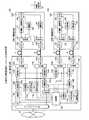
図2において、集中基地局100と遠隔基地局200Aは光ファイバ11,12を介して接続され、集中基地局100と遠隔基地局200Bは光ファイバ13,14を介して接続される。無線端末局30は遠隔基地局200A,200Bの双方と通信可能な位置にあるものとする。集中基地局100にはバックボーンネットワーク20が接続される。 In FIG. 2, the
集中基地局100を構成するデータバッファ部101、フレーム構築部102A、制御部103、データ信号用の変調器104A、合波器105A,105B、制御信号用の変調器106A,106B、E/O107A,107B、O/E108A,108B、復調器109A,109Bは、図5に示す従来のものと同様の構成である。ただし、ここでは送信ダイバーシチを行うためにフレーム構築部102Aおよび変調器104Aのみ記載し、変調器104Aから出力するデータ信号をそれぞれ遠隔基地局200A,200Bに送信する構成とし、遠隔基地局200Bへ独立に送信するデータ信号を処理するフレーム構築部102Bおよび変調器104Bは省略している。 The
遠隔基地局200Aおよび200Bを構成するO/E201、SW204、アンテナ205、復調器206、増幅器207、E/O208は、図5に示す従来のものと同様の構成である。 The O /
本実施形態では、以上の構成に加えて遠隔基地局間同期のために、集中基地局100に符号発生器111A,111B、相関検波器112A,112B、下り方向に挿入する遅延線113A,113B、上り方向に挿入する遅延線114A,114B、分波器115A,115Bを備え、遠隔基地局200Aおよび200Bに分波器211および合波器213を備える。さらに、遠隔基地局200Aおよび200Bに増幅・減衰器212を備え、無線端末局30でダイバーシチ合成するための信号レベルを調整する。また、集中基地局100に復調器109A,109Bの各出力を合成する合成器116を備える。なお、集中基地局100において、復調器109A,109Bでそれぞれ復調されたデータ信号がダイバーシチ合成の対象でなければその一方を破棄するか、双方のデータ信号を個別にデータバッファ分波器101に出力する(図面ではその経路は省略)。 In the present embodiment, in addition to the above configuration, for synchronization between remote base stations,
(遠隔基地局間の同期処理系)
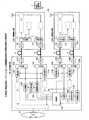
図3は、本発明の無線通信システムにおける遠隔基地局間の同期処理系の構成を示す。ここでは、図2に示す集中基地局100および遠隔基地局200A,200Bの実施形態から遠隔基地局間の同期処理に関するものを抽出した構成を示す。(Synchronous processing system between remote base stations)
FIG. 3 shows a configuration of a synchronization processing system between remote base stations in the wireless communication system of the present invention. Here, the structure which extracted the thing regarding the synchronous process between remote base stations from embodiment of the
図3において、符号発生器111Aは相関性に優れるPN系列符号を生成し、変調器106Aに出力する。変調器106Aは、このPN系列符号信号を変調して例えばBPSK信号に変換し、データ信号および制御信号とは異なる無線周波数帯に変換して合波器105Aに出力する。合波器105Aは、遅延線113Aを介して入力するデータ信号と、制御信号またはBPSK信号を周波数多重する機能を有する。合波器105Aから出力される無線周波数帯のBPSK信号は、E/O107Aで光信号に変換され、光ファイバ11を介して遠隔基地局200Aに伝送される。 In FIG. 3, the
遠隔基地局200Aに伝送された光信号は、O/E201で電気信号に変換され、分波器211に入力する。分波器211は、周波数多重されたデータ信号と、制御信号またはBPSK信号を分波する機能を有し、分波されたBPSK信号は合波器213に入力する。合波器213は、遠隔基地局200Aから集中基地局100に送信するデータ信号と、集中基地局100にループバックするBPSK信号を周波数多重する機能を有する。合波器213から出力される無線周波数帯のBPSK信号は、E/O208で光信号に変換され、光ファイバ12を介して集中基地局100に伝送される。 The optical signal transmitted to the
集中基地局100に伝送された光信号は、O/E108Aで電気信号に変換され、分波器115Aに入力する。分波器115Aは、周波数多重されたデータ信号とBPSK信号を分波する機能を有し、分波されたBPSK信号は相関検波器112Aに入力し、データ信号は遅延線114Aに入力する。相関検波器112Aは、符号発生器111Aから出力されるPN系列符号信号と、遠隔基地局200Aを経由してループバックしてきたBPSK信号の相関を検波し、相関信号を制御部103に出力する。 The optical signal transmitted to the
同様に、集中基地局100と遠隔基地局200Bとの間においてもPN系列符号信号を変調したBPSK信号をループバックし、相関検波器112Bで符号発生器111Bから出力されるPN系列符号信号との相関を検波し、相関信号を制御部103に出力する。なお、図2および図3に示す実施形態は、遠隔基地局200A,200Bに伝送された光信号を電気信号に変換し、BPSK信号を分波器211で分波して合波器213に入力し、再度光信号に変換してループバックする構成であるが、BPSK信号のみを変換した光信号の場合には、光カプラ等を用いて光ファイバ11から光ファイバ12、光ファイバ13から光ファイバ14に光信号のままでループバックする構成としてもよい。 Similarly, the BPSK signal obtained by modulating the PN sequence code signal is looped back between the
制御部103は、相関検波器112A,112Bから出力される相関信号から遅延時間差を検出し、その遅延時間が同じになるように、遠隔基地局200Aに対応する遅延線113A,114Aと、遠隔基地局Bに対応する遅延線113B,114Bの値を調整する。例えば、集中基地局100と遠隔基地局200Aの往復遅延時間に対して集中基地局100と遠隔基地局200Bの往復遅延時間が2τ遅くなっていれば、集中基地局100から遠隔基地局200Aへの下り方向の遅延線113Aに遅延量τを設定し、上り方向の遅延線114Aに遅延量τを設定する。これにより、集中基地局100から遅延線113A,113Bを介して遅延調整して送信したデータ信号は、光ファイバ11,13を介して遠隔基地局200A,200Bに同時に受信され、同じタイミングで中継送信することができる。また、遠隔基地局200Aおよび200Bから同時に送信したデータ信号は、光ファイバ12,14を介してその遅延差に対応して集中基地局100に順次受信され、遅延線114A,114Bを介して遅延調整して同じタイミングで復調することができる。 The
このようにして遠隔基地局200A,200B間の同期をとることができるが、以上の同期処理を図1に示す集中基地局100と全ての遠隔基地局200との間で行う。 Although the remote base stations 200A and 200B can be synchronized in this way, the above synchronization processing is performed between the
(サイトダイバーシチの処理系)
図4は、本発明の無線通信システムにおけるサイトダイバーシチの処理系の構成を示す。ここでは、図2に示す集中基地局100および遠隔基地局200A,200Bの実施形態からサイトダイバーシチ処理に関するものを抽出した構成を示す。なお、遠隔基地局200A,200Bは、すでに遠隔基地局間の同期がとれているものとする。(Site diversity processing system)
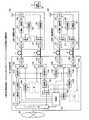
FIG. 4 shows a configuration of a site diversity processing system in the wireless communication system of the present invention. Here, the structure which extracted the thing regarding a site diversity process from embodiment of the
図4において、バックボーンネットワーク20から無線端末局30に対して送信されるデータ信号は、集中基地局100のデータバッファ部101を介してフレーム構築部102Aに入力する。フレーム構築部102Aは、制御部103から入力するタイミング信号をもとに無線フレームを構築して変調器104Aに出力する。変調器104Aは、無線フレームのデータ信号を変調し、さらに無線周波数帯に周波数変換する。この無線周波数帯のデータ信号は、遅延線113A,113Bを介してそれぞれ合波器105A,105Bに入力する。また、制御部103は遠隔基地局200A,200Bの制御に用いる制御信号を出力し、変調器106A,106Bはそれぞれの制御信号を変調し、データ信号とは異なる無線周波数帯に変換して合波器105A,105Bにそれぞれ出力する。異なる無線周波数帯に変換されたデータ信号と制御信号は合波器105A,105Bでそれぞれ周波数多重され、さらにE/O107A,107Bで光信号に変換され、それぞれ光ファイバ11,13を介して遠隔基地局200A,200Bに伝送される。 In FIG. 4, a data signal transmitted from the
なお、集中基地局100と遠隔基地局200A,200Bの遅延時間差は、遠隔基地局間の同期処理による遅延線113A,113Bの遅延設定により解消され、集中基地局100で2分岐されたデータ信号は同時に遠隔基地局200A,200Bに到着する。 Note that the delay time difference between the
遠隔基地局200A,200Bに伝送された光信号は、それぞれO/E201で電気信号に変換され、分波器211に入力する。分波器211は、無線周波数帯で周波数多重されたデータ信号と制御信号を分波し、データ信号は増幅・減衰器212で増幅または減衰され、さらにスイッチ(SW)204を介してアンテナ205から無線端末局30に送信される。一方、分波器211で分波された制御信号は復調器206に入力して復調され、タイミング制御信号として増幅・減衰器212の制御およびスイッチ204の送受信切替制御に用いられる。なお、増幅・減衰器212の制御について後述する。 The optical signals transmitted to the
無線端末局30から送信された信号は、遠隔基地局200A,200Bのアンテナ205に受信され、それぞれスイッチ204を介して増幅器207に入力して最適レベルに調整され、さらにE/O208で光信号に変換され、それぞれ光ファイバ12,14を介して集中基地局100に伝送される。集中基地局100に伝送された光信号は、O/E108A,108Bで電気信号に変換され、遅延線114A,114Bを介して復調器109A,109Bに入力する。ここで、集中基地局100と遠隔基地局200A,200Bの遅延時間差は、遠隔基地局間の同期処理による遅延線114A,114Bの遅延設定により解消され、無線端末局30から遠隔基地局200A,200Bを介してそれぞれ集中基地局100に伝送された信号は、同時に復調器109A,109Bに入力して復調される。 The signal transmitted from the
復調器109A,109Bは、無線端末局30から送信され、遠隔基地局200A,200Bを介して集中基地局100に中継伝送された信号をそれぞれ復調する。このとき、復調したデータ信号の先頭部分のプリアンブル部からフレームタイミングや送信局を検出し、さらに復調したプリアンブルを既知のプリアンブルで除算することにより、遠隔基地局200A,200Bと無線端末局30との間の伝搬路係数(伝搬路の複素振幅など)をそれぞれ推定し、制御部103に通知する。制御部103は、復調器109A,109Bで復調したデータ信号が共に無線端末局30から送信されたものであることを確認すると、それぞれ検出されるプリアンブル部のタイミングを比較し、遠隔基地局200A,200Bと無線端末局30の伝搬路差を検出する。この伝搬路差がすでに説明したGI以下であれば、遠隔基地局200A,200Bは無線端末局30に対するGI内遠隔基地局群として確認できる。
制御部103は、この確認処理により復調器109A,109Bで復調したデータ信号を合成することによりCINRの改善が可能と判断し、復調器109A,109Bからデータ信号が合成器116に入力されるように制御する。このとき、制御部103は、合成後のCINRが最大になるような重み付け係数を算出し、復調器109A,109Bに通知する。復調器109A,109Bはこの重み付け係数に応じて復調したデータ信号にそれぞれ重み付け処理して出力する。合成器116は、最大比合成によりCINRを改善したデータ信号をビット判定し、データバッファ部101を介してバックボーンネットワーク20に出力する。 The
また、制御部103は、復調器109A,109Bで復調したデータ信号のプリアンブル部のタイミングを比較し、遠隔基地局200A,200Bと無線端末局30の伝搬路差がGI以上となる場合には、各データ信号は互いに干渉波となるので、例えば各データ信号のSNRを比較して大きい方を選択して合成器116に入力し、他方のデータ信号を破棄する。 Further, the
一般に、3以上の遠隔基地局から伝送されたデータ信号については、例えば各データ信号のSNRを比較し、SNRが最大となるデータ信号を送信した遠隔基地局を基準として、プリアンブル部のタイミングを比較して得られる上記伝搬路差がGI以下となるデータ信号を合成器116で最大比合成し、GI以上となるデータ信号を破棄する。 In general, for data signals transmitted from three or more remote base stations, for example, the SNR of each data signal is compared, and the timing of the preamble portion is compared based on the remote base station that transmitted the data signal with the maximum SNR. Then, the data signal having the propagation path difference of GI or less obtained in this way is combined at the maximum ratio by the
また、制御部103は、復調器109A,109Bで復調したデータ信号の送信局が異なる場合には、それぞれ個別にビット判定してデータバッファ部101を介してバックボーンネットワーク20に出力する制御を行う。なお、このための処理系は図面では省略されている。 In addition, when the transmission stations of the data signals demodulated by the demodulators 109 </ b> A and 109 </ b> B are different, the
また、制御部103は復調器109A,109Bから取得した情報に基づいて、集中基地局100から無線端末局30に送信するデータ信号が遠隔基地局200A,200Bでそれぞれ中継送信されるときに、無線端末局30で合成後のCINRが最大になるように変調器104Aで重み付け処理を行う。変調器104で重み付け処理されたデータ信号は、遅延線113A,113Bを介してそれぞれ遠隔基地局200A,200Bに送信される。これにより、遠隔基地局200A,200Bから同一の信号が同時にかつ重み付けされて送信され、それぞれの信号をGI以内で受信する無線端末局3は最大比合成を行ってCINRを改善する。 Further, based on the information acquired from the
また、制御部103は、受信したデータ信号のプリアンブル部のタイミングを比較し、遠隔基地局200A,200Bと無線端末局30の伝搬路差がGI以上となる場合に、そのSNRを比較して小さい方の遠隔基地局から無線端末局30に送信する信号が干渉波となるために、当該遠隔基地局に対して
(1) 送信を停止する、
(2) 送信電力を低減する、
(3) 無線端末局30における干渉量を推定し、当該干渉量が許容値以下と推定されれば 特に制御せずに送信しない
などの制御信号を送信し、復調器206から増幅・減衰器212を制御して行う。In addition, the
(1) Stop sending,
(2) reduce transmission power,
(3) The amount of interference in the
一般に、3以上の遠隔基地局に送信するデータ信号については、同様に基準となる遠隔基地局に対して伝搬路差がGI以下となるGI内遠隔基地局群の遠隔基地局に対してデータ信号を送信し、GI以上となるGI外遠隔基地局群の遠隔基地局に対するデータ信号について (1)〜(3) のいずれかの制御を行う。 In general, for data signals to be transmitted to three or more remote base stations, the data signals for the remote base stations in the GI remote base station group whose propagation path difference is GI or less with respect to the remote base station that is the reference in the same manner. And control any one of (1) to (3) for the data signal to the remote base station in the remote base station group outside GI that is equal to or higher than GI.
10,11,12,13,14 光ファイバ
20 バックボーンネットワーク
30,31,32 無線端末局
100 集中基地局
101 データバッファ部
102 フレーム構築部
103 制御部
104 変調器(データ信号用)
105 合波器
106 変調器(制御信号用)
107 電気/光変換器(E/O)
108 光/電気変換器(O/E)
109 復調器
111 符号発生器
112 相関検波器
113,114 遅延線
115 分波器
116 合成器
200 遠隔基地局
201 光/電気変換器(O/E)
203 増幅器
204 スイッチ(SW)
205 アンテナ
206 復調器
207 増幅器
208 電気/光変換器(E/O)
211 分波器
212 増幅・減衰器
213 合波器10, 11, 12, 13, 14
105 multiplexer 106 modulator (for control signal)
107 Electric / optical converter (E / O)
108 Optical / electrical converter (O / E)
109 Demodulator 111 Code Generator 112 Correlation Detector 113, 114 Delay Line 115
211
Claims (12)
Translated fromJapanese前記集中基地局は、
前記集中基地局から前記無線端末局に送信するデータ信号と、前記複数の遠隔基地局をそれぞれ制御する制御信号と、PN系列符号信号を互いに異なる無線周波数帯の信号に変換して合波し、その合波した信号を光信号に変換し、前記光伝送路を介して前記複数の遠隔基地局に送信する送信手段と、
前記複数の遠隔基地局で折り返され、前記光伝送路を介して前記集中基地局に送信された光信号を受信して電気信号に変換し、前記PN系列符号信号を出力する受信手段と、
前記複数の遠隔基地局ごとに、前記送信手段および前記受信手段からそれぞれPN系列符号信号を入力して相関を検波し、相関信号を出力する相関検波手段と、
前記複数の遠隔基地局に対応する前記相関信号から遅延時間差を検出し、前記集中基地局と前記複数の遠隔基地局との間の遅延時間が同じになるように各遠隔基地局に対する遅延時間を決定する制御手段と、
前記決定した遅延時間に従って、前記集中基地局から前記複数の遠隔基地局に送信するデータ信号の遅延量を設定し、かつ前記複数の遠隔基地局から前記集中基地局に受信するデータ信号の遅延量を設定する遅延手段とを備え、
前記複数の遠隔基地局は、それぞれ受信した光信号を電気信号に変換し、前記データ信号と前記制御信号と前記PN系列符号信号に分波し、分波した前記PN系列符号信号と、前記遠隔基地局から前記集中基地局に送信するデータ信号を合波し、その合波した信号を光信号に変換して前記集中基地局に折り返すループバック手段を備え、
さらに、前記集中基地局の前記制御手段は、前記無線端末局から送信され前記複数の遠隔基地局を介して中継送信されたデータ信号から、前記無線端末局と前記複数の遠隔基地局との遅延時間をそれぞれ検出し、前記複数の遠隔基地局について当該遅延時間が所定の時間T以内であるT内遠隔基地局群と、所定の時間T以上であるT外遠隔基地局群に区分し、T内遠隔基地局群の遠隔基地局から受信するデータ信号を合成して出力し、T外遠隔基地局群の遠隔基地局から受信するデータ信号を破棄し、前記無線端末局に送信するデータ信号を前記複数の遠隔基地局に送信する際に、T外遠隔基地局群の遠隔基地局に対してこのデータ信号が前記無線端末局で干渉とならないように前記制御信号により制御する構成であり、
前記複数の遠隔基地局は、前記ループバック手段で分波した前記制御信号に従って、前記集中基地局から前記無線端末局に中継送信するデータ信号の送信電力を制御する手段を備えた
ことを特徴とする無線通信システム。A central base station and a plurality of remote base stations are connected via an optical transmission line, a plurality of remote base stations and a wireless terminal station are connected via a wireless line, and the wireless terminal station and the central base station are connected via a remote base station. In a wireless communication system that performs communication,
The centralized base station is
A data signal transmitted from the centralized base station to the wireless terminal station, a control signal for controlling each of the plurality of remote base stations, and a PN sequence code signalare converted into signals of different radio frequency bands and combined, Transmitting means for convertingthe combined signal into an optical signal, and transmitting to the plurality of remote base stations via the optical transmission path;
Receiving meansfor converting into an electric signal, andoutputs the PN sequence code signal of the plurality of folded at the remote base stationreceives the optical signal transmitted to the centralized base station via said optical transmission path,
Correlation detection means for detecting a correlation by inputting a PN sequence code signal from each of the transmission means and the reception means and outputting a correlation signal for each of the plurality of remote base stations;
A delay time difference is detected from the correlation signal corresponding to the plurality of remote base stations, and a delay time for each remote base station is set so that a delay time between the centralized base station and the plurality of remote base stations is the same. Control means to determine;
In accordance with the determined delay time, a delay amount of a data signal transmitted from the central base station to the plurality of remote base stations is set, and a delay amount of a data signal received from the plurality of remote base stations to the central base station And delay means for setting
The plurality of remote base stations respectivelyconvertreceived optical signalsinto electrical signals, demultiplex the data signals, the control signals, and the PN sequence code signals, and the demultiplexed PN sequence code signals; A loopback means forcombining data signals to be transmitted from a base station to the centralized base station,converting thecombined signal into an optical signal and turning back to the centralized base station,
Further, the control means of the centralized base station may determine a delay between the wireless terminal station and the plurality of remote base stations from a data signal transmitted from the wireless terminal station and relay-transmitted via the plurality of remote base stations. Detecting each time, and classifying the plurality of remote base stations into a T-base remote base station group in which the delay time is within a predetermined time T and a T-outside remote base station group having a predetermined time T or more; A data signal received from a remote base station in the inner remote base station group is synthesized and output, a data signal received from a remote base station in the outer T remote base station group is discarded, and a data signal to be transmitted to the wireless terminal station is When transmitting to the plurality of remote base stations, the data signal is controlled by the control signal so that the radio terminal station does not interfere with the remote base station of the T external remote base station group,
The plurality of remote base stations are provided with means for controlling transmission power of data signals relayed from the centralized base station to the wireless terminal station according to the control signal demultiplexed by the loopback means. Wireless communication system.
前記集中基地局の前記制御手段は、前記無線端末局から送信され前記複数の遠隔基地局で中継送信されたデータ信号から、前記無線端末局と前記複数の遠隔基地局との伝搬路係数をそれぞれ検出し、前記T内遠隔基地局群の遠隔基地局から受信するデータ信号を合成する際に、前記伝搬路係数に応じたデータ信号の重み付けにより最大比合成されるように制御し、前記無線端末局に送信するデータ信号を前記T内遠隔基地局群の遠隔基地局に送信する際に、前記伝搬路係数に応じたデータ信号の重み付けにより前記無線端末局で最大比合成されるように制御する構成である
ことを特徴とする無線通信システム。The wireless communication system according to claim1 , wherein
The control means of the centralized base station determines propagation path coefficients between the wireless terminal station and the plurality of remote base stations from data signals transmitted from the wireless terminal station and relay-transmitted by the plurality of remote base stations, respectively. Detecting and combining the data signals received from the remote base stations in the T remote base station group so that the maximum ratio is combined by weighting the data signals according to the propagation path coefficient, and the wireless terminal When transmitting a data signal to be transmitted to a station to a remote base station in the intra-T remote base station group, control is performed so that the radio terminal station performs maximum ratio synthesis by weighting the data signal in accordance with the propagation path coefficient. A wireless communication system characterized by having a configuration.
前記集中基地局の前記制御手段は、前記T外遠隔基地局群の遠隔基地局に対して前記無線端末局に送信するデータ信号の送信を停止する制御を行う構成である
ことを特徴とする無線通信システム。The wireless communication system according to claim1 , wherein
The control unit of the centralized base station is configured to perform control to stop transmission of a data signal to be transmitted to the wireless terminal station to a remote base station in the group of remote base stations outside T. Communications system.
前記集中基地局の前記制御手段は、前記T外遠隔基地局群の遠隔基地局に対して前記無線端末局に送信するデータ信号の送信電力を低減する制御を行う構成である
ことを特徴とする無線通信システム。The wireless communication system according to claim1 , wherein
The control means of the centralized base station is configured to perform control to reduce the transmission power of the data signal transmitted to the wireless terminal station for the remote base stations of the T external remote base station group. Wireless communication system.
前記集中基地局の前記制御手段は、前記T外遠隔基地局群の遠隔基地局が前記無線端末局に与える干渉量を推定し、当該干渉量が前記無線端末局の許容値以下であれば、前記T外遠隔基地局群の遠隔基地局への制御を行わない構成である
ことを特徴とする無線通信システム。The wireless communication system according to claim1 , wherein
The control means of the centralized base station estimates the amount of interference given to the wireless terminal station by a remote base station in the remote base station group outside T, and if the amount of interference is less than the allowable value of the wireless terminal station, A wireless communication system, characterized in that the remote base station group of the T external remote base station group is not controlled.
前記遠隔基地局と前記無線端末局はOFDM(Orthogonal Frequency Division Multiplexing)信号により無線通信を行い、前記所定の時間TがOFDM信号に規定されるガードインターバルに設定された
ことを特徴とする無線通信システム。The wireless communication system according to claim1 , wherein
The remote base station and the wireless terminal station perform wireless communication by an OFDM (Orthogonal Frequency Division Multiplexing) signal, and the predetermined time T is set to a guard interval defined in the OFDM signal. .
前記集中基地局は、
送信手段で、前記集中基地局から前記無線端末局に送信するデータ信号と、前記複数の遠隔基地局をそれぞれ制御する制御信号と、PN系列符号信号を互いに異なる無線周波数帯の信号に変換して合波し、その合波した信号を光信号に変換し、前記光伝送路を介して前記複数の遠隔基地局に送信する処理を行い、
受信手段で、前記複数の遠隔基地局で折り返され、前記光伝送路を介して前記集中基地局に送信された光信号を受信して電気信号に変換し、前記PN系列符号信号を出力する処理を行い、
相関検出手段で、前記複数の遠隔基地局ごとに、前記送信手段および前記受信手段からそれぞれPN系列符号信号を入力して相関を検波し、相関信号を出力する処理を行い、
制御手段で、前記複数の遠隔基地局に対応する前記相関信号から遅延時間差を検出し、前記集中基地局と前記複数の遠隔基地局との間の遅延時間が同じになるように各遠隔基地局に対する遅延時間を決定する処理を行い、
遅延手段で、前記決定した遅延時間に従って、前記集中基地局から前記複数の遠隔基地局に送信するデータ信号の遅延量を設定し、かつ前記複数の遠隔基地局から前記集中基地局に受信するデータ信号の遅延量を設定する処理を行い、
前記複数の遠隔基地局は、ループバック手段で、それぞれ受信した光信号を電気信号に変換し、前記データ信号と前記制御信号と前記PN系列符号信号に分波し、分波した前記PN系列符号信号と、前記遠隔基地局から前記集中基地局に送信するデータ信号を合波し、その合波した信号を光信号に変換して前記集中基地局に折り返す処理を行い、
さらに、前記集中基地局の前記制御手段は、前記無線端末局から送信され前記複数の遠隔基地局を介して中継送信されたデータ信号から、前記無線端末局と前記複数の遠隔基地局との遅延時間をそれぞれ検出し、前記複数の遠隔基地局について当該遅延時間が所定の時間T以内であるT内遠隔基地局群と、所定の時間T以上であるT外遠隔基地局群に区分し、T内遠隔基地局群の遠隔基地局から受信するデータ信号を合成して出力し、T外遠隔基地局群の遠隔基地局から受信するデータ信号を破棄し、前記無線端末局に送信するデータ信号を前記複数の遠隔基地局に送信する際に、T外遠隔基地局群の遠隔基地局に対してこのデータ信号が前記無線端末局で干渉とならないように前記制御信号により制御する処理を行い、
前記複数の遠隔基地局は、前記ループバック手段で分波した前記制御信号に従って、前記集中基地局から前記無線端末局に中継送信するデータ信号の送信電力を制御する処理を行う
ことを特徴とする無線通信方法。A central base station and a plurality of remote base stations are connected via an optical transmission line, a plurality of remote base stations and a wireless terminal station are connected via a wireless line, and the wireless terminal station and the central base station are connected via a remote base station. In a wireless communication method for performing communication,
The centralized base station is
The transmission meansconvertsthe data signal transmitted from the centralized base station to the wireless terminal station, the control signal for controlling each of the plurality of remote base stations, and the PN sequence code signalinto signalsof different radio frequency bands. Combining , converting thecombined signal into an optical signal, performing processing to transmit to the plurality of remote base stations via the optical transmission path
A receiving unit that receives an optical signal that is returnedby the plurality of remote base stations and transmitted to the centralized base station via the optical transmission path, converts the optical signal intoan electrical signal,and outputs the PN sequence code signal; And
In the correlation detection unit, for each of the plurality of remote base stations, a PN sequence code signal is input from each of the transmission unit and the reception unit to detect a correlation, and a process of outputting a correlation signal is performed.
The control means detects a delay time difference from the correlation signal corresponding to the plurality of remote base stations, and each remote base station is configured to have the same delay time between the centralized base station and the plurality of remote base stations. Process to determine the delay time for
A delay unit sets a delay amount of a data signal transmitted from the central base station to the plurality of remote base stations according to the determined delay time, and data received from the plurality of remote base stations to the central base station Perform processing to set the signal delay amount,
The plurality of remote base stationsconvert eachreceived optical signalinto an electrical signalby a loopback means,demultiplex the data signal, the control signal, and the PN sequence code signal, and demultiplex the PN sequence code.There linesand signal, the data signal multiplexes transmitted from the remote base station to the centralized base station, thethus multiplexed signal isconverted into an optical signal folded back to the centralized base stationprocess,
Further, the control means of the centralized base station may determine a delay between the wireless terminal station and the plurality of remote base stations from a data signal transmitted from the wireless terminal station and relay-transmitted via the plurality of remote base stations. Detecting each time, and classifying the plurality of remote base stations into a T-base remote base station group in which the delay time is within a predetermined time T and a T-outside remote base station group having a predetermined time T or more; A data signal received from a remote base station in the inner remote base station group is synthesized and output, a data signal received from a remote base station in the outer T remote base station group is discarded, and a data signal to be transmitted to the wireless terminal station is When transmitting to the plurality of remote base stations, perform processing to control by the control signal so that this data signal does not interfere with the wireless terminal station for the remote base stations of the T external remote base station group,
The plurality of remote base stations perform processing for controlling transmission power of a data signal relayed from the centralized base station to the wireless terminal station according to the control signal demultiplexed by the loopback means. Wireless communication method.
前記集中基地局の前記制御手段は、前記無線端末局から送信され前記複数の遠隔基地局で中継送信されたデータ信号から、前記無線端末局と前記複数の遠隔基地局との伝搬路係数をそれぞれ検出し、前記T内遠隔基地局群の遠隔基地局から受信するデータ信号を合成する際に、前記伝搬路係数に応じたデータ信号の重み付けにより最大比合成されるように制御し、前記無線端末局に送信するデータ信号を前記T内遠隔基地局群の遠隔基地局に送信する際に、前記伝搬路係数に応じたデータ信号の重み付けにより前記無線端末局で最大比合成されるように制御する処理を行う
ことを特徴とする無線通信方法。The wireless communication method according to claim7 , wherein
The control means of the centralized base station determines propagation path coefficients between the wireless terminal station and the plurality of remote base stations from data signals transmitted from the wireless terminal station and relay-transmitted by the plurality of remote base stations, respectively. Detecting and combining the data signals received from the remote base stations in the T remote base station group so that the maximum ratio is combined by weighting the data signals according to the propagation path coefficient, and the wireless terminal When transmitting a data signal to be transmitted to a station to a remote base station in the intra-T remote base station group, control is performed so that the radio terminal station performs maximum ratio synthesis by weighting the data signal in accordance with the propagation path coefficient. A wireless communication method characterized by performing processing.
前記集中基地局の前記制御手段は、前記T外遠隔基地局群の遠隔基地局に対して前記無線端末局に送信するデータ信号の送信を停止する制御を行う
ことを特徴とする無線通信方法。The wireless communication method according to claim7 , wherein
The wireless communication method, wherein the control means of the centralized base station performs control to stop transmission of a data signal to be transmitted to the wireless terminal station with respect to the remote base stations of the non-T remote base station group.
前記集中基地局の前記制御手段は、前記T外遠隔基地局群の遠隔基地局に対して前記無線端末局に送信するデータ信号の送信電力を低減する制御を行う
ことを特徴とする無線通信方法。The wireless communication method according to claim7 , wherein
The wireless communication method, wherein the control means of the centralized base station performs control to reduce transmission power of a data signal transmitted to the wireless terminal station for a remote base station in the group of remote base stations outside T .
前記集中基地局の前記制御手段は、前記T外遠隔基地局群の遠隔基地局が前記無線端末局に与える干渉量を推定し、当該干渉量が前記無線端末局の許容値以下であれば、前記T外遠隔基地局群の遠隔基地局への制御を行わない
ことを特徴とする無線通信方法。The wireless communication method according to claim7 , wherein
The control means of the centralized base station estimates the amount of interference given to the wireless terminal station by a remote base station in the remote base station group outside T, and if the amount of interference is less than the allowable value of the wireless terminal station, The wireless communication method according to claim 1, wherein control of the remote base station group outside the T is not performed.
前記遠隔基地局と前記無線端末局はOFDM(Orthogonal Frequency Division Multiplexing)信号により無線通信を行い、前記所定の時間TがOFDM信号に規定されるガードインターバルに設定された
ことを特徴とする無線通信方法。The wireless communication method according to claim7 , wherein
The wireless base station and the wireless terminal station perform wireless communication using an OFDM (Orthogonal Frequency Division Multiplexing) signal, and the predetermined time T is set to a guard interval defined in the OFDM signal. .
Priority Applications (1)
| Application Number | Priority Date | Filing Date | Title |
|---|---|---|---|
| JP2008046124AJP4909301B2 (en) | 2008-02-27 | 2008-02-27 | Wireless communication system and wireless communication method |
Applications Claiming Priority (1)
| Application Number | Priority Date | Filing Date | Title |
|---|---|---|---|
| JP2008046124AJP4909301B2 (en) | 2008-02-27 | 2008-02-27 | Wireless communication system and wireless communication method |
Publications (2)
| Publication Number | Publication Date |
|---|---|
| JP2009206735A JP2009206735A (en) | 2009-09-10 |
| JP4909301B2true JP4909301B2 (en) | 2012-04-04 |
Family
ID=41148585
Family Applications (1)
| Application Number | Title | Priority Date | Filing Date |
|---|---|---|---|
| JP2008046124AExpired - Fee RelatedJP4909301B2 (en) | 2008-02-27 | 2008-02-27 | Wireless communication system and wireless communication method |
Country Status (1)
| Country | Link |
|---|---|
| JP (1) | JP4909301B2 (en) |
Families Citing this family (16)
| Publication number | Priority date | Publication date | Assignee | Title |
|---|---|---|---|---|
| JP5455026B2 (en)* | 2009-10-28 | 2014-03-26 | 京セラ株式会社 | Radio base station and radio communication method |
| JP5367843B2 (en)* | 2009-12-16 | 2013-12-11 | 株式会社東芝 | Radio signal processing apparatus and radio apparatus |
| JP5189111B2 (en)* | 2010-01-07 | 2013-04-24 | 株式会社エヌ・ティ・ティ・ドコモ | Radio base station apparatus, radio communication system, and radio communication method |
| US9020555B2 (en)* | 2010-04-05 | 2015-04-28 | Intel Corporation | System and method for performance enhancement in heterogeneous wireless access network employing distributed antenna system |
| US9276685B2 (en) | 2011-10-14 | 2016-03-01 | Qualcomm Incorporated | Distributed antenna systems and methods of wireless communications for facilitating simulcasting and de-simulcasting of downlink transmissions |
| US9312941B2 (en)* | 2011-10-14 | 2016-04-12 | Qualcomm Incorporated | Base stations and methods for facilitating dynamic simulcasting and de-simulcasting in a distributed antenna system |
| JP6141087B2 (en)* | 2013-04-23 | 2017-06-07 | 日本放送協会 | Send back signal delay correction device |
| JP6244988B2 (en)* | 2014-03-06 | 2017-12-13 | 三菱電機株式会社 | Signal synchronization circuit |
| JP6397059B2 (en)* | 2015-05-22 | 2018-09-26 | 株式会社Nttドコモ | User equipment and base station |
| WO2019039096A1 (en)* | 2017-08-21 | 2019-02-28 | ソニー株式会社 | Information processing device, base station, terminal device, and information processing method |
| WO2019116491A1 (en)* | 2017-12-14 | 2019-06-20 | 株式会社日立国際電気 | Radio communication system and radio communication method |
| AU2019216879B2 (en)* | 2018-02-08 | 2023-12-14 | Bae Systems Australia Limited | Large-scale distributed timing, calibration and control system |
| JP7293886B2 (en)* | 2019-06-06 | 2023-06-20 | 日本電信電話株式会社 | Wireless communication system, wireless communication method, control station device, base station device, and terminal station device |
| JP7388907B2 (en)* | 2019-12-16 | 2023-11-29 | 株式会社日立国際電気 | wireless communication system |
| JP2023102678A (en)* | 2022-01-12 | 2023-07-25 | 株式会社Nttドコモ | Radio wave hologram communication device and radio wave hologram communication method |
| JP7595609B2 (en)* | 2022-03-29 | 2024-12-06 | Kddi株式会社 | Base station, central station and phased array antenna system |
Family Cites Families (4)
| Publication number | Priority date | Publication date | Assignee | Title |
|---|---|---|---|---|
| JPH05264729A (en)* | 1992-03-23 | 1993-10-12 | Clarion Co Ltd | Range finder |
| JP3191256B2 (en)* | 1995-07-10 | 2001-07-23 | 日本電信電話株式会社 | Synchronization method between base stations |
| JPH11113049A (en)* | 1997-09-30 | 1999-04-23 | Matsushita Electric Ind Co Ltd | Wireless communication system |
| JP2006115318A (en)* | 2004-10-15 | 2006-04-27 | Mitsubishi Electric Corp | Receiver |
- 2008
- 2008-02-27JPJP2008046124Apatent/JP4909301B2/ennot_activeExpired - Fee Related
Also Published As
| Publication number | Publication date |
|---|---|
| JP2009206735A (en) | 2009-09-10 |
Similar Documents
| Publication | Publication Date | Title |
|---|---|---|
| JP4909301B2 (en) | Wireless communication system and wireless communication method | |
| US11265074B2 (en) | Noise cancelling amplify-and-forward (in-band) relay with self-interference cancellation | |
| JP5406923B2 (en) | System and method for a configurable time division duplex interface | |
| JP5583664B2 (en) | System and method for switching synchronized time division duplex signals | |
| KR100974456B1 (en) | Short-range cellular booster | |
| KR100871229B1 (en) | Wired / wireless integrated network system performing a hybrid duplexing wireless communication service and signal control method therefor | |
| US20200204249A1 (en) | Radio relay apparatus and operating method therefor | |
| CN101322327B (en) | Method, device and system for relay information in wireless relay network | |
| JP4256804B2 (en) | Multi antenna system | |
| KR20010055088A (en) | Optical communication apparatus | |
| JP7107022B2 (en) | Wireless communication system, wireless communication method and base station device | |
| JP2008530946A (en) | Method and apparatus for cooperative relay | |
| US8630579B2 (en) | Wireless communication apparatus, wireless communication method, and wireless communication system | |
| KR20080107795A (en) | Time Division Redundant Optical Wireless Relay System for Automatically Controlling the Gain of RS Receiver and Signal Control Method Using The Same | |
| WO2020226844A1 (en) | Transport cable redundancy in a distributed antenna system using digital transport | |
| KR101282069B1 (en) | Rf repeater for mimo communication | |
| KR101041483B1 (en) | Cooperative Transmission Device and Method in Relay Network | |
| US12267763B2 (en) | Relaying in a wireless communication network | |
| CN115426010B (en) | 5G MIMO signal transmission system and method | |
| KR100679397B1 (en) | Optical relay apparatus and method having a phase modulation transmit diversity function |
Legal Events
| Date | Code | Title | Description |
|---|---|---|---|
| A621 | Written request for application examination | Free format text:JAPANESE INTERMEDIATE CODE: A621 Effective date:20100121 | |
| A977 | Report on retrieval | Free format text:JAPANESE INTERMEDIATE CODE: A971007 Effective date:20111012 | |
| A131 | Notification of reasons for refusal | Free format text:JAPANESE INTERMEDIATE CODE: A131 Effective date:20111115 | |
| A521 | Written amendment | Free format text:JAPANESE INTERMEDIATE CODE: A523 Effective date:20111214 | |
| TRDD | Decision of grant or rejection written | ||
| A01 | Written decision to grant a patent or to grant a registration (utility model) | Free format text:JAPANESE INTERMEDIATE CODE: A01 Effective date:20120110 | |
| A01 | Written decision to grant a patent or to grant a registration (utility model) | Free format text:JAPANESE INTERMEDIATE CODE: A01 | |
| A61 | First payment of annual fees (during grant procedure) | Free format text:JAPANESE INTERMEDIATE CODE: A61 Effective date:20120113 | |
| FPAY | Renewal fee payment (event date is renewal date of database) | Free format text:PAYMENT UNTIL: 20150120 Year of fee payment:3 | |
| R150 | Certificate of patent or registration of utility model | Ref document number:4909301 Country of ref document:JP Free format text:JAPANESE INTERMEDIATE CODE: R150 Free format text:JAPANESE INTERMEDIATE CODE: R150 | |
| S531 | Written request for registration of change of domicile | Free format text:JAPANESE INTERMEDIATE CODE: R313531 | |
| R350 | Written notification of registration of transfer | Free format text:JAPANESE INTERMEDIATE CODE: R350 | |
| LAPS | Cancellation because of no payment of annual fees |