JP4908219B2 - Configurable PLC and SCADA based control system and method - Google Patents
Configurable PLC and SCADA based control system and methodDownload PDFInfo
- Publication number
- JP4908219B2 JP4908219B2JP2006533233AJP2006533233AJP4908219B2JP 4908219 B2JP4908219 B2JP 4908219B2JP 2006533233 AJP2006533233 AJP 2006533233AJP 2006533233 AJP2006533233 AJP 2006533233AJP 4908219 B2JP4908219 B2JP 4908219B2
- Authority
- JP
- Japan
- Prior art keywords
- user
- control system
- scada
- configurable control
- data
- Prior art date
- Legal status (The legal status is an assumption and is not a legal conclusion. Google has not performed a legal analysis and makes no representation as to the accuracy of the status listed.)
- Expired - Lifetime
Links
Images


Classifications
- G—PHYSICS
- G05—CONTROLLING; REGULATING
- G05B—CONTROL OR REGULATING SYSTEMS IN GENERAL; FUNCTIONAL ELEMENTS OF SUCH SYSTEMS; MONITORING OR TESTING ARRANGEMENTS FOR SUCH SYSTEMS OR ELEMENTS
- G05B19/00—Programme-control systems
- G05B19/02—Programme-control systems electric
- G05B19/18—Numerical control [NC], i.e. automatically operating machines, in particular machine tools, e.g. in a manufacturing environment, so as to execute positioning, movement or co-ordinated operations by means of programme data in numerical form
- G05B19/409—Numerical control [NC], i.e. automatically operating machines, in particular machine tools, e.g. in a manufacturing environment, so as to execute positioning, movement or co-ordinated operations by means of programme data in numerical form characterised by using manual data input [MDI] or by using control panel, e.g. controlling functions with the panel; characterised by control panel details or by setting parameters
- G—PHYSICS
- G05—CONTROLLING; REGULATING
- G05B—CONTROL OR REGULATING SYSTEMS IN GENERAL; FUNCTIONAL ELEMENTS OF SUCH SYSTEMS; MONITORING OR TESTING ARRANGEMENTS FOR SUCH SYSTEMS OR ELEMENTS
- G05B19/00—Programme-control systems
- G—PHYSICS
- G05—CONTROLLING; REGULATING
- G05B—CONTROL OR REGULATING SYSTEMS IN GENERAL; FUNCTIONAL ELEMENTS OF SUCH SYSTEMS; MONITORING OR TESTING ARRANGEMENTS FOR SUCH SYSTEMS OR ELEMENTS
- G05B2219/00—Program-control systems
- G05B2219/30—Nc systems
- G05B2219/32—Operator till task planning
- G05B2219/32404—Scada supervisory control and data acquisition
- G—PHYSICS
- G05—CONTROLLING; REGULATING
- G05B—CONTROL OR REGULATING SYSTEMS IN GENERAL; FUNCTIONAL ELEMENTS OF SUCH SYSTEMS; MONITORING OR TESTING ARRANGEMENTS FOR SUCH SYSTEMS OR ELEMENTS
- G05B2219/00—Program-control systems
- G05B2219/30—Nc systems
- G05B2219/32—Operator till task planning
- G05B2219/32413—Pc generates control strategy, download in plc to monitor and react to events
- G—PHYSICS
- G05—CONTROLLING; REGULATING
- G05B—CONTROL OR REGULATING SYSTEMS IN GENERAL; FUNCTIONAL ELEMENTS OF SUCH SYSTEMS; MONITORING OR TESTING ARRANGEMENTS FOR SUCH SYSTEMS OR ELEMENTS
- G05B2219/00—Program-control systems
- G05B2219/30—Nc systems
- G05B2219/36—Nc in input of data, input key till input tape
- G05B2219/36125—Select out of library, beforehand only functions needed for part program
- Y—GENERAL TAGGING OF NEW TECHNOLOGICAL DEVELOPMENTS; GENERAL TAGGING OF CROSS-SECTIONAL TECHNOLOGIES SPANNING OVER SEVERAL SECTIONS OF THE IPC; TECHNICAL SUBJECTS COVERED BY FORMER USPC CROSS-REFERENCE ART COLLECTIONS [XRACs] AND DIGESTS
- Y02—TECHNOLOGIES OR APPLICATIONS FOR MITIGATION OR ADAPTATION AGAINST CLIMATE CHANGE
- Y02P—CLIMATE CHANGE MITIGATION TECHNOLOGIES IN THE PRODUCTION OR PROCESSING OF GOODS
- Y02P90/00—Enabling technologies with a potential contribution to greenhouse gas [GHG] emissions mitigation
- Y02P90/02—Total factory control, e.g. smart factories, flexible manufacturing systems [FMS] or integrated manufacturing systems [IMS]
Landscapes
- Engineering & Computer Science (AREA)
- Physics & Mathematics (AREA)
- General Physics & Mathematics (AREA)
- Automation & Control Theory (AREA)
- Human Computer Interaction (AREA)
- Manufacturing & Machinery (AREA)
- Stored Programmes (AREA)
- Programmable Controllers (AREA)
Description
Translated fromJapanese発明の分野
本発明は、一般に、製造プロセスを制御及び監視するシステムに関し、より詳細には、最小限のソフトウェア修正で設定可能なシステムに関する。The present invention relates generally to systems for controlling and monitoring manufacturing processes, and more particularly to systems that can be configured with minimal software modifications.
発明の背景
現在の製造監視制御システムは、監視及び制御される処理システムに対するオブジェクト又は構成要素の追加を許容するが、そのようなオブジェクト又は構成要素の追加は、固定された論理的構成及び/又は入出力(IO)構成の範囲内でなされる。与えられた固定の構成の範囲外で運転するためには、ユーザは、監視制御システムのソフトウェアを修正しなければならない。そのためには、典型的に、熟練のソフトウェア技術者が要求され、必要とされるコーディングは、通常、非常に複雑で時間がかかり、デバッグが難しい。従って、従来技術の課題を克服するために、別個の属性及び論理を有する様々なツール及び装置を設定する際に、ユーザがオブジェクトを容易に定義することを許容する、柔軟な製造プロセス監視制御システムの開発に対する長年のニーズが存在する。また、ユーザに対して一切のプログラム技術を要求せずに、ユーザが製造プロセス内の任意の所望の場所に入出力(I/O)を容易に割り当てること、システム設定を容易に更新する能力を有すること、及び、コンピュータ化された制御システムへの最小限の手動処理により監視制御機能を達成することを許容するシステムに対するニーズが存在する。BACKGROUND OF THE INVENTION Although current manufacturing monitoring and control systems allow the addition of objects or components to the monitored and controlled processing system, the addition of such objects or components is a fixed logical configuration and / or This is done within the scope of the input / output (IO) configuration. In order to operate outside the scope of a given fixed configuration, the user must modify the supervisory control system software. This typically requires skilled software engineers, and the required coding is usually very complex, time consuming and difficult to debug. Thus, a flexible manufacturing process monitoring and control system that allows a user to easily define objects when setting up various tools and devices with distinct attributes and logic to overcome the problems of the prior art. There is a long-standing need for development. In addition, the ability of the user to easily assign input / output (I / O) to any desired location in the manufacturing process and to easily update the system settings without requiring any program technology from the user. There is a need for a system that has and allows to achieve supervisory control functions with minimal manual processing to a computerized control system.
固体素子又は集積回路素子のような電子デバイスの製造は、最新技術のシステムでは自動配布ネットワークを通じてシステムに供給される化学物質の利用に依存する。そのような処理システムは、また、典型的に、ポンプ、混合器、広範な配管、バルブボックスなどを含み、それらは全て、安全と、様々な化学物質の関連する利用場所への時宜にあった供給とのための、制御機構及びシステムを必要とする。現在利用されている制御システムは、典型的に、カスタマイズされた又は少なくとも部分的にカスタマイズされたソフトウェアを利用してプログラムされた、商業的に利用可能な又は独自の制御ハードウェア・システムに依存する。これらの既知のシステムは、化学物質システムの任意の変化に対応するためにソフトウェアが修正されることを要し、典型的に、高度に熟練したソフトウェア技術者によるサービスを必要とする。その結果、そのようなシステムは柔軟性が限られ、システムに変更を設けるために膨大な時間を必要とするため、ダウンタイムによるコストと、追加人員への依存を増大させる。 The manufacture of electronic devices, such as solid state or integrated circuit elements, relies on the use of chemicals supplied to the system through an automated distribution network in state-of-the-art systems. Such processing systems also typically include pumps, mixers, extensive piping, valve boxes, etc., all of which were safe and timely to the relevant locations of various chemicals. Requires control mechanisms and systems for supply. Currently utilized control systems typically rely on commercially available or proprietary control hardware systems programmed using customized or at least partially customized software . These known systems require software to be modified to accommodate any changes in chemical systems and typically require service by highly skilled software technicians. As a result, such systems are limited in flexibility and require a significant amount of time to make changes to the system, increasing costs due to downtime and reliance on additional personnel.
発明の概要
従来技術の課題を考慮し、本発明は、工業プロセスの制御監視を実行するコンピュータ化された設定可能制御設定可能制御システム(CCS)であって、一切のソフトウェア又はプログラミングの修正を必要としないシステム設定手段を利用した迅速な開発及び修正を可能とするシステム(CCS)を提供する。本発明を、電子デバイスの製造又は組み立てと関連する化学物質システムにおいて、化学物質の供給と、ツール、バルブボックス、及び他の装置の動作との制御監視における利用について説明するが、本発明はそれに限定されるものではなく、他の製造環境での利用に適用可能であることに注意されたい。SUMMARY OF THE INVENTION In view of the problems of the prior art, the present invention is a computerized configurable control configurable control system (CCS) that performs industrial process control monitoring and requires no software or programming modifications Provided is a system (CCS) that enables rapid development and correction using a system setting means that does not. The present invention will be described for use in controlling and monitoring the supply of chemicals and the operation of tools, valve boxes and other equipment in chemical systems associated with the manufacture or assembly of electronic devices. It should be noted that the present invention is not limited and is applicable to use in other manufacturing environments.
本発明は、関連する化学物質システム又は製造プロセスのダウンタイムを実質的に除去しながら、製造システムを容易に設定し、ツール及びバルブボックスを追加又は削除し、化学物質の配布を修正し、利用地点を削除又は追加することを可能とする手段を含む。本発明の1つの実施の形態において、設定可能制御システム(CCS)は、3つの構成要素を備えるソフトウェア・アプリケーションを含む。第1のソフトウェア構成要素は設定ツールであり、第2の構成要素はCCS管理制御及びデータ収集(SCADA)アプリケーションであり、第3の構成要素はCCS PLC(プログラム可能論理コントローラ)アプリケーションである。 The present invention makes it easy to set up a manufacturing system, add or delete tools and valve boxes, modify the distribution of chemicals, and use while substantially eliminating downtime of the associated chemical system or manufacturing process. Includes means that allow points to be deleted or added. In one embodiment of the invention, a configurable control system (CCS) includes a software application that comprises three components. The first software component is a configuration tool, the second component is a CCS management control and data collection (SCADA) application, and the third component is a CCS PLC (programmable logic controller) application.
設定ツール構成要素は、好ましい実施の形態において、化学物質システムのような製造システム又は処理システムの物理的構成及び論理的構成をユーザが定義することを可能とする、フォーム・ベースのグラフィカル・ユーザ・インターフェース(GUI)を含む。 The configuration tool component, in a preferred embodiment, is a form-based graphical user user that allows the user to define the physical and logical configuration of a manufacturing or processing system such as a chemical system. Includes an interface (GUI).
SCADAソフトウェア構成要素は、設定ツールから化学物質監視システム(CMS)及びプログラム可能論理コンピュータ(PLC)アプリケーションへと設定ファイルをダウンロードする手段を提供する。SCADAアプリケーションは、また、変化を配備し、設定ツールによって定義されたシステムに基づいてアニメーション及び警告を自動生成する。 The SCADA software component provides a means for downloading configuration files from configuration tools to chemical monitoring systems (CMS) and programmable logic computer (PLC) applications. The SCADA application also deploys changes and automatically generates animations and alerts based on the system defined by the configuration tool.
第3のソフトウェア構成要素は、入出力(IO)を割り当てることにより、及び設定ツールにより定義されたシステムに基づいて論理を割り当てることにより、設定ファイルを用いて製造システム又は処理システムのオブジェクト及び論理を定義するCCS PLCアプリケーションである。 The third software component uses the configuration file to assign objects and logic of the manufacturing system or processing system by assigning input / output (IO) and assigning logic based on the system defined by the setup tool. A CCS PLC application to be defined.
例えば化学物質処理システムにおいて利用される場合の本発明の様々な実施の形態は、一切のソフトウェア修正を必要とせずに、ユーザがツールを容易に追加又は削除し、バルブボックスを追加又は削除し、IOコントローラを追加又は削除し、装置コントローラを追加又は削除し、化学物質の配布を変更し、制御信号を修正することなどを可能とする「プラグ・アンド・プレイ」手段を提供する。 For example, various embodiments of the present invention when utilized in a chemical processing system may allow a user to easily add or remove tools, add or remove valve boxes, without requiring any software modifications, A “plug and play” means is provided that allows adding or removing IO controllers, adding or removing device controllers, changing chemical distribution, modifying control signals, and the like.
以下において、本発明の様々な実施の形態を、同様のアイテムが同一の参照符号で指示される図面を参照して説明する。 In the following, various embodiments of the present invention will be described with reference to the drawings, in which like items are designated with the same reference numerals.
発明の詳細な説明
本発明は、製造処理システムのユーザが、システム・ソフトウェアを変更することなくシステムを設定及び再設定することを可能とする設定可能制御システム(CCS)を提供する。本発明の様々な実施の形態の動作を、典型的には固体素子即ち半導体の製造者によって利用される化学物質処理システムであって、ソフトウェアの変更を一切要求することなく、ユーザが関連する化学物質供給ネットワークの所望の変更に応じて、関連する処理システムにおいて構成要素を迅速に追加、修正、削除し、制御信号を変更することを可能とする化学物質処理システムに関連して説明する。典型的に、本発明の様々な実施の形態は、化学物質処理システムの運転のダウンタイムを必要とせずに、制御システムにそのような変更がなされることを可能とする。DETAILED DESCRIPTION OF THE INVENTION The present invention provides a configurable control system (CCS) that allows a user of a manufacturing processing system to set up and reconfigure a system without changing system software. The operation of the various embodiments of the present invention is typically performed by a chemical processing system utilized by a solid state or semiconductor manufacturer, without requiring any software changes, A description will be given in connection with a chemical processing system that allows components to be quickly added, modified, deleted and control signals changed in the associated processing system in response to a desired change in the material supply network. Typically, the various embodiments of the present invention allow such changes to be made to the control system without requiring downtime of the chemical treatment system operation.
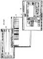
図1を参照して、本発明の1つの実施の形態において、本発明の設定可能制御システム(CCS)は、化学物質監視サーバ1(CMSサーバ)と、プログラム可能ロジック・コントローラ8(PLC)とを含む。CMSサーバ1は、典型的に、データベース及びグラフィカル・ユーザ・インターフェース・ソフトウェア・プログラム、並びに管理制御及びデータ収集(SCADA)アプリケーション11ソフトウェア・プログラムをロードされたパーソナル・コンピュータである。ユーザは、コンピュータ・モニタ(図示せず)に画面イメージとして表示されるフォーム・ベースのグラフィカル・ユーザ・インターフェース(GUI)に設定情報を入力し、データは設定ツール2に入力される。設定ツール2は、データテーブルを含むデータベースファイル4に、設定データベースを自動生成する。CCSは、また、PLCアプリケーション9を通じてプログラムされるプログラム可能論理コントローラ(PLC)8を含む。設定データベース4は、SCADAアプリケーション11及びPLCアプリケーション9のそれぞれに対するデータベースを含むことに注意されたい。CMSサーバ1は、変更を配備し、設定ツール2を通して定義された処理システムに基づいてアニメーション及び警告を自動生成する。PLCアプリケーション9は、設定ツール2により、確立された設定データフェイル4を介して定義された処理システムに基づいて、IO及び論理を割り当てる。 Referring to FIG. 1, in one embodiment of the present invention, the configurable control system (CCS) of the present invention includes a chemical substance monitoring server 1 (CMS server), a programmable logic controller 8 (PLC), including. The
設定ツール2への情報入力の後で、画面イメージを利用するために、ユーザは、SCADAソフトウェア・プログラムを開き、SCADAアプリケーション11ソフトウェアのメインページから配備ツールを開く。配備ツール3のためのユーザ・インターフェースを提供する画面イメージを利用して、ユーザは、SCADA設定データベース5及びPLCデータアレイ或いはデータベース10の更新へと進むことができる。図2に更に示す通り、カスタマイズされたスクリプトを有するダウンロード・アプリケーション7が、配備ツール3からPLCデータアレイ10へのデータベースのダウンロードに利用される。 After entering information into the configuration tool 2, to use the screen image, the user opens the SCADA software program and opens the deployment tool from the main page of the SCADA
配備ツール3は、設定ツール2を介してユーザによってなされた任意の変更について、SCADA設定データベース5を更新する。SCADAアプリケーション11は、更新されたSCADA設定データベース5に基づいてSCADAディスプレイ・ソフトウェア6を更新することにより、自動的に応答する。配備ツール3は、また、上記の通り、データベース4からPLC8へPLC設定データをダウンロードする。本発明の好ましい実施の形態において、PLC8は、Allen-Bradley Control Logix Processorによって提供される。PLCデータアレイ10の設定情報を、PLC8が読み取り可能なアレイフォーマットに変換するために、Rockwell Automation RSLinxのような標準的なドライバが利用される。 The deployment tool 3 updates the SCADA
SCADAアプリケーション11、ダウンロード・アプリケーション7及びPLCアプリケーション9は、同一のパーソナルコンピュータ(PC)にロードされなくともよいことに注意されたい。いずれにせよ、CMSサーバ1を提供するパーソナルコンピュータは、また、プログラム可能なヒューマン・マシン・インターフェース(HMI)又はマン・マシン・インターフェース(MMI)を表す。また、本発明において、先に述べた通り、設定データベース4及びGUIプログラムが、SCADAアプリケーション11及びPLCアプリケーション9の両方のデータベース作成に利用されることに注意することが重要である。PLCデータアレイ10の構造は、RSLinxが、配備ツール3からPLC8へ効率的にデータをダウンロードすることを可能とする。 Note that the SCADA
以下に示す通り、グラフィカル・ユーザ・インターフェースの利用は、ユーザが、例えば複数の相互に接続された装置、ツール、コントローラなどからなる製造加工システムの物理的及び論理的な構成を定義することを可能とする。例示のため、本発明の利用法を、典型的には半導体デバイスの形成において利用される化学物質処理システムと関連付けて説明する。そのような化学物質システムは、典型的に、化学物質配布モジュール、混合モジュール、収集モジュール、バルブボックス、プログラム可能論理コントローラ、フィールドIOパネル、加工ツール、様々な化学物質を供給から利用地点へと運搬及び配送する配管、インターフェース・パネル、コンピュータ・ディスプレイ、様々な化学物質製品を保持するタンクなどを含む。設定ツール2は、本発明によって提供される所望の機能を提供するために、様々なソフトウェア開発環境、及びウェブベース言語を含む様々な言語でプログラムされ得る。好ましい実施の形態において、設定ツール2は、マイクロソフト社によって提供されるMicrosoft Access(登録商標)ベースのソフトウェア・アプリケーションである。 As shown below, the use of a graphical user interface allows the user to define the physical and logical configuration of a manufacturing and processing system consisting of multiple interconnected devices, tools, controllers, etc. And For purposes of illustration, the use of the present invention will be described in connection with a chemical processing system typically used in the formation of semiconductor devices. Such chemical systems typically carry chemical distribution modules, mixing modules, collection modules, valve boxes, programmable logic controllers, field IO panels, processing tools, various chemicals from supply to point of use. And piping to deliver, interface panels, computer displays, tanks holding various chemical products, etc. The configuration tool 2 can be programmed in a variety of languages, including various software development environments and web-based languages, to provide the desired functionality provided by the present invention. In the preferred embodiment, the configuration tool 2 is a Microsoft Access® based software application provided by Microsoft Corporation.
設定ツール2によって作成される設定データベース4は、好ましい実施の形態において、この例では化学物質システムである関連する製造処理システムの設定を記載する、Microsoft Access(登録商標)ベースのソフトウェアである。設定データベースファイル4は、例示的なシステムについて以下に示される変数であって、SCADAアプリケーション11及びプログラム可能論理コントローラ(PLC)アプリケーション9によって読み取られる変数を含む。設定データベースファイル4は、また、拡張可能マークアップ言語(XML)のような、コンピュータ・ネットワークを介して通信するための他のソフトウェアによって提供されても良い。 The configuration database 4 created by the configuration tool 2 is Microsoft Access®-based software that describes the settings of the associated manufacturing processing system, which in this example is a chemical system in the preferred embodiment. The configuration database file 4 includes the variables shown below for the exemplary system that are read by the SCADA
配備ツール3は、上記の通り設定ファイル4からデータをダウンロードするためのSCADAソフトウェア・アプリケーションである。好ましい実施の形態において、配備ツール3は、ゼネラル・エレクトリック社によって提供されるCimplicityソフトウェアに基づく。好ましい実施の形態においては、SCADAアプリケーション11も、ゼネラル・エレクトリック社のCimplicityベースのアプリケーションである。 The deployment tool 3 is a SCADA software application for downloading data from the setting file 4 as described above. In a preferred embodiment, the deployment tool 3 is based on Cimplicity software provided by General Electric Company. In the preferred embodiment, SCADA
CMSサーバ1は、関連システムの状態を監視するようプログラムされ、関連する処理システムのユーザ又は操作者に対して主要なヒューマン/マシン・インターフェースを提供する。SCADAアプリケーション11は、本発明とともに利用するために適用可能な任意の製造処理システムのために開発され得る。 The
PLCアプリケーション9は、本例では化学物質システムである関連システムのオブジェクト及び論理を定義するために設定ファイル4からデータを受信するソフトウェア・アプリケーションである。好ましい実施の形態において、1つ又は複数の関連するAllen-Bradleyプログラム可能論理コントローラ8をプログラムするために(Allen-Bradley社によって提供される)Allen-Bradleyソフトウェアが利用される。 The PLC application 9 is a software application that receives data from the configuration file 4 to define the objects and logic of the related system, which in this example is a chemical substance system. In the preferred embodiment, Allen-Bradley software (provided by Allen-Bradley) is utilized to program one or more associated Allen-Bradley programmable logic controllers 8.
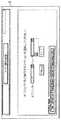
図2を参照して、化学物質処理システム又はネットワーク13における利用のために、本発明の様々な実施の形態が示される。本発明の様々な実施の形態は、上記の通り、化学物質処理システムにおける利用について説明されるが、本発明はそのように限定されるものではなく、化学物質処理システム以外においても利用され得ることに注意されたい。図示される通り、化学物質処理システムは、CCS設定ツール2、CMSサーバ1、単一の又は冗長化されたPLC8(PLC8A及び8Bにより冗長化されたものとして示される)、及び、本発明の先に説明した他の構成要素を含む。また、SCADAアプリケーション・プログラム11は、CMSサーバ1をプログラムするために利用される。PLCアプリケーション9は、PLC8のために利用される。 With reference to FIG. 2, various embodiments of the present invention are shown for use in a chemical processing system or
化学物質処理システムの例としての構成要素は、また、化学物質配布モジュール12、IOコントローラ14、ツール18、及びバルブボックス16を含む。ネットワーク設計は、例えば、既存システムの動作を中断することなしに調剤器及び混合器の追加を可能とすることにより、実質的にダウンタイムを除去する。データ集積装置としても知られる冗長化されたPLCコントローラ8は、配布システムを制御する。コントローラ14は、本例において化学製品を処理ツール18まで安全に配送するために必要とされる信号及び論理を管理するために連帯して動作可能である。SCADAアプリケーション11は、監視のみを提供し、化学製品の配送の制御とは関連しない。 Exemplary components of the chemical treatment system also include a
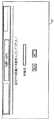
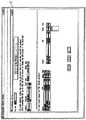
図3に示す通り、典型的な従来の化学物質処理システム、並びに非化学物質処理システムは、システムを初期設定するため、及び、その後にシステムに変更を加えるために、熟練したソフトウェア技術者によって提供されなければならない時間がかかるコーディングを必要とする。画面イメージ26、28及び30は、システムを構成及び変更するために必要とされる。画面28は、典型的に扱われなければならない膨大なコーディングを示す。 As shown in FIG. 3, a typical conventional chemical treatment system, as well as a non-chemical treatment system, is provided by a skilled software engineer to initialize the system and subsequently make changes to the system. Requires time consuming coding that must be done.
本発明の様々な実施の形態の利用を通じて、従来技術において必要とされる時間のかかるコーディングは、実質的に取り除かれる。図2の化学物質システム13及び他の製造システムについて、本発明のCCSシステムは使用前に初期化されなければならない。 Through the use of various embodiments of the present invention, the time consuming coding required in the prior art is substantially eliminated. For the
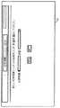
本発明を利用する利点を説明する。図4を参照して、化学物質システム13を初期化し、後に変更するために、ユーザは、CMSサーバ1のディスプレイ又はモニタを操作して、例えば図4に示されるメイン選択画面32を稼動させる。ユーザは、まず、「オブジェクト」に対するプルダウン・スクリーンに取り掛かり、本例では、オブジェクト・メニューから「部屋」を選択する。この選択に続いて、ユーザは、「アクション」エントリに対するプルダウンメニューを利用して、本例では「追加」を選択してから、「次へ」を選択又は押下する。すると、ユーザに対し、図5に示した部屋追加画面イメージ34が表示される。ユーザは、所望の部屋名を入力して、終了を押す。 Advantages of using the present invention will be described. Referring to FIG. 4, in order to initialize and change the
システムの初期設定を続けて、ユーザは、次に、図4のメイン選択画面32を自動的に表示される。メイン選択画面32が表示されると、ユーザは、「オブジェクト」に対するプルダウンメニューを利用して、所望の化学物質システムを選択する。これに続いて、ユーザは、「アクション」に対するプルダウンメニューに取り掛かり、追加を選択してから、「次へ」を選択する。本CCSは、ユーザに対し、「化学物質システム−追加」のための画面イメージ36(図6参照)を提示することによって応答する。ユーザは、所望の化学物質名及び化学物質部屋を入力し、「終了」を押す(押すと表記される場合は常に、この動作が、通常関連するコンピュータ・マウスを用いて達成されることに注意されたい)。 Continuing with the initial setup of the system, the user then automatically displays the
本発明に係るCCSは、ユーザを自動的に画面32のメイン選択画面(図4)に戻す。本例において、ユーザは、オブジェクトのプルダウンメニューからFIOP(フィールドIOパネル)を選択し、アクション・プルダウンから追加を選択して、次へを押す。すると、CCSは、ユーザに、フィールドIOパネル−追加の画面イメージ38(図7参照)を提示することによって応答する。ユーザはFIOP名を入力し、プルダウンメニューからLAN(ローカル・エリア・ネットワーク)を選択し、プルダウンメニューを用いて「ノード」を選択する。これらの選択を行ってから、ユーザは終了を押下する。次に、ユーザは、図4のメイン選択画面32に自動的に戻される。ユーザは、オブジェクトのプルダウンメニューから所望のCDM(化学物質配布モジュール)を選択し、アクションに対するプルダウンメニューから追加を選択して、次へを押す。 The CCS according to the present invention automatically returns the user to the main selection screen of the screen 32 (FIG. 4). In this example, the user selects FIOP (field IO panel) from the object pull-down menu, selects add from the action pull-down, and presses Next. The CCS then responds by presenting the user with the field IO panel-additional screen image 38 (see FIG. 7). The user inputs the FIOP name, selects LAN (Local Area Network) from the pull-down menu, and selects “Node” using the pull-down menu. After making these selections, the user presses End. Next, the user is automatically returned to the
CCSは、図8に示すCDM−追加の画面イメージ40を提供し、該画面により、ユーザは、関連するプルダウンメニューから化学物質、所望の種別のCDM12(化学物質配布モジュール)及びIPアドレスを選択して、選択したCDM12の名前を入力し、終了を押す。それに応答して、CCSは、ユーザが所望の種別の信号、適用可能なFIOP、適切なスロット及び地点を選択することを可能とするプルダウンメニューを表示する。ユーザは、また、プルダウンメニューを利用して、新しく追加されたCDM12に対する供給情報及びトグル情報を選択しなければならない。この選択をしてから、ユーザは終了を押し、CCSは、ユーザが予備のIOを選択して終了を押すことを可能とするIO割り当て画面表示を表示することによって応答する。 The CCS provides the CDM-
CCSは、表示を自動的にメイン選択画面32(図4参照)に戻すことによって応答する。ユーザは、次に、オブジェクトのプルダウンからバルブボックスを選択し、アクション・メニューをプルダウンして追加を選択して、次へを押す。CCSは、バルブボックス−追加の画面イメージ42(図9参照)を表示することによって応答する。ユーザは、次に、全ての情報を提供するために、空白のデータ欄に入力するか、適用可能な場合には関連するプルダウンメニューを利用することによってデータを入力し、次へを押す。CCSは、ツール−追加の画面イメージ44(図10参照)を表示することによって応答する。ユーザは、次に、適切なデータ欄にツール名を入力し、データ欄の関連するプルダウンメニューからツール種別を選択し、オプションとして、ツールの場所を入力しなければならない。ユーザは、また、適切な矢印キーを押して、化学物質を、関連するツールボックスに対する「化学物質」に移動させ、次へを押さなければならない。 The CCS responds by automatically returning the display to the main selection screen 32 (see FIG. 4). The user then selects a valve box from the object pull-down, pulls down the action menu, selects Add, and presses Next. The CCS responds by displaying the valve box-additional screen image 42 (see FIG. 9). The user then enters data by entering in the blank data field or using the associated pull-down menu, if applicable, to provide all the information and press Next. The CCS responds by displaying a tool-additional screen image 44 (see FIG. 10). The user must then enter the tool name in the appropriate data field, select the tool type from the associated pull-down menu in the data field, and optionally enter the location of the tool. The user must also press the appropriate arrow key to move the chemical to “Chemical” for the associated toolbox and press Next.
ユーザは、次に、IO選択画面(図示せず)の画面イメージを提示され、画面に向かって予備のIOを選択し、終了を押す。CCSは、図4のメイン選択画面32を表示することによって応答する。該画面により、ユーザは、適切なプルダウンメニューを使ってオブジェクトからバルブボックスを選択し、アクションから追加を選択して、次へを押す。 The user is then presented with a screen image of an IO selection screen (not shown), selects a spare IO towards the screen, and presses end. The CCS responds by displaying the
図11に示すように、ユーザは、次に、ユーザがツールへの供給を行うバルブボックスを選択することを可能とする画面イメージ46を提示される。該選択は、関連するプルダウンメニューを利用して空白欄を埋めることによってなされる。CCSは、ユーザが次へを押したことに応答して、ユーザがFIOP及びツール準備完了信号のためのモジュールを選択することを可能とする新しい画面イメージ(図示せず)を提供する。 As shown in FIG. 11, the user is then presented with a
これにより、例としての化学物質システムの初期設定が完了する。
例としての化学物質システムの設定に続いて、ユーザは、何らかの処理フロー経路、又は設定の他の側面を変更したいと望むかもしれない。図12のフロー図は、ユーザが例としての化学物質システムにおいて容易に所望の変更を行うことを可能とするステップ50〜62を示す。ステップ50〜62は、図示する通り、ユーザに対し非常に少ない要求をする。例えば、例としての化学物質システムにおける変更を行うために、ユーザは、本例において図4のメインメニュー32に向かって、「ツール追加1:フォーム」に対する画面イメージ70(図13参照)を引き出し、適切なツール名を入力してから、プルダウンメニューを使ってツール種別を挿入し、オプションで、ツール場所を含める。上記の通り、ユーザは、矢印のうちの適切なものを押して、表示されたツールに対する化学物質を選択する。この後、ユーザは次へを押す。CCSは、「ツール追加2:フォーム」の画面イメージ72(図14参照)を提示することによって応答する。ユーザは、次に、表示されたデータ欄の様々なブルダウンメニューに向かって必要とされるIOを割り当ててから、終了を押す。CCSは、図15に示される「配備ツール.CLM」に対する画面イメージ74を稼動させることによって応答する。ユーザは、コンピュータ・マウスを用いて所望のトグルボタンを押して、先に行われた変化を配備すればよい。This completes the initial setup of the exemplary chemical system.
Following the setup of the example chemical system, the user may wish to change some process flow path, or other aspect of the setup. The flow diagram of FIG. 12 illustrates steps 50-62 that allow the user to easily make desired changes in the example chemical system. Steps 50-62 make very few requests to the user as shown. For example, in order to make a change in the example chemical substance system, the user draws a screen image 70 (see FIG. 13) for “tool addition 1: form” toward the
本ヒューマン/マシン・インターフェースは、図4〜15に関連して上記で部分的に説明された。この化学物質処理システムの例において、プルダウンメニューと関連付けられたメイン選択画面、及び適切なプルダウンメニュー及びデータ入力のためのデータ欄を含む関連する他の画面イメージの例示的な利用は、ユーザが関連する製造処理システムを容易に設定及び制御することを可能にするために利用される。例えば、例としての化学物質システムにおいて、例示された画面イメージは、本発明において、多くの異なる機能を促進するために開発され得る。これらの機能には、ツールの追加又は削除、化学物質のツールへの追加又はツールからの削除、ツールの名称変更、バルブボックスの追加又は削除、FIOP(フィールドIOパネル)の追加又は削除、ツール種別の追加又は削除、バルブボックス種別の追加又は削除、補助信号の追加又は削除、FMS(工場監視システム)の追加又は削除、CDM(化学物質配布モジュール)の追加又は削除などが含まれる。これにより、ユーザは、本発明の利用を通じて、ソフトウェア修正の必要なしに、製造処理システムを迅速に設定又は再設定することが可能である。 The human / machine interface has been described in part above with respect to FIGS. In this example of a chemical treatment system, the exemplary use of the main selection screen associated with the pull-down menu and other related screen images including the appropriate pull-down menu and data fields for data entry is relevant to the user. To make it easy to set up and control a manufacturing processing system. For example, in an exemplary chemical system, the illustrated screen images can be developed to facilitate many different functions in the present invention. These functions include the addition or deletion of tools, the addition or deletion of chemical substances to or from a tool, the name change of a tool, the addition or deletion of a valve box, the addition or deletion of a FIOP (field IO panel), the tool type Addition / deletion, valve box type addition / deletion, auxiliary signal addition / deletion, FMS (factory monitoring system) addition / deletion, CDM (chemical substance distribution module) addition / deletion, and the like. This allows the user to quickly set up or reconfigure the manufacturing process system through the use of the present invention without the need for software modifications.
化学物質処理システムにおける利用のための例示された設定ツール2は、ユーザがシステム・オブジェクトを追加、編集及び削除することを可能とする。これらのオブジェクトは、化学物質室、調剤又は混合システム、バルブボックス、利用地点及び補助信号を含み得る。また、設定ツール2は、ユーザが、柔軟性を提供し、構築コスト及びハードウェアコストを制限するために、システムIO信号を制御システムの任意の位置に配置するIOAnywhereシステムを使って信号位置を設定することを可能とする。また、設定ツール2は、ユーザが、例えばバルブボックスが特定の数の漏出センサーを有することを定義するように、各システム構成要素に必要とされる信号を設定することを可能とする。また、設定ツール2は、ユーザに、例えばツール及び供給バルブを作動させるために必要とされる信号のような、システム動作論理を設定する能力を与える。また、設定ツール2は、ユーザが、例えばバルブボックスの漏れがあった場合の分離又は停止プロトコルのような、処理システムの特定の要求に基づく安全論理を設定することを可能とする。 The illustrated configuration tool 2 for use in a chemical processing system allows a user to add, edit and delete system objects. These objects may include chemical rooms, dispensing or mixing systems, valve boxes, usage points and auxiliary signals. The configuration tool 2 also allows the user to set the signal position using an IOAnywhere system that places system IO signals anywhere in the control system to provide flexibility and limit construction and hardware costs. It is possible to do. The configuration tool 2 also allows the user to set the required signals for each system component, for example to define that the valve box has a certain number of leak sensors. The configuration tool 2 also gives the user the ability to set system operating logic, such as the signals required to operate the tool and supply valve. The configuration tool 2 also allows the user to set safety logic based on specific requirements of the processing system, such as a separation or shutdown protocol in the event of a valve box leak.
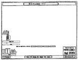
図16〜20は、本例ではツールを削除するために設定制御システムを変更するプロセスを示す。図16は、PC上のSCADA配布状況画面を示す。図16のCDMは、当初4つのツール(T1、T2、T3及びT4)がCDMに接続されることを示す。 FIGS. 16-20 illustrate the process of changing the configuration control system to remove tools in this example. FIG. 16 shows the SCADA distribution status screen on the PC. The CDM in FIG. 16 shows that initially four tools (T1, T2, T3 and T4) are connected to the CDM.
ユーザは、製造プロセスからツールを除去することにより製造装置を修正することを決定した場合、図17の設定ツールのメイン選択画面から始めなければならない。ユーザは、プルダウンメニューを用いてツール及び削除を選択してから、「次へ」を選択して図18に示されるように続く。 If the user decides to modify the manufacturing device by removing the tool from the manufacturing process, he must start with the main selection screen of the setting tool of FIG. The user selects tools and deletes using the pull-down menu and then selects “Next” to continue as shown in FIG.
次に現れる画面は、図18に示すツール−削除画面である。ユーザは、プルダウンメニューを用いて削除するツールを選択する。本例では、ユーザはツール4(T4)を設定制御システムから削除するよう選択する。ユーザは、終了を押して、設定データベースへの更新を実行する。 The next screen that appears is the tool-delete screen shown in FIG. The user selects a tool to be deleted using a pull-down menu. In this example, the user selects to delete tool 4 (T4) from the setting control system. The user presses Finish to execute the update to the setting database.
次に、ユーザは、SCADAアプリケーションから配備ツールにアクセスする。配備ツール画面(図19)において、ユーザは、PLC8A、8Bに新しいデータをダウンロードし、図2に示すように、CMSサーバ1のSCADA表示及びデータベースを更新する。最適な実施の形態において、図2に示すように、2つの冗長化されたPLC8A、8Bが存在する。そのため、ユーザは、PLC8Bが製造プロセスを制御している間に、PLC8に新しいデータをダウンロードすることができる。PLC8Aが更新されると、ユーザは、制御をPLC8Aに切り替えて、PLC8Bを更新する。ユーザは、また、図19に示す対応するボタンを押すことにより、SCADA表示及びデータベースを更新する。 The user then accesses the deployment tool from the SCADA application. On the deployment tool screen (FIG. 19), the user downloads new data to the PLCs 8A and 8B, and updates the SCADA display and database of the
図20は、更新されたSCADA配布のSCADA画面を示す。予期された通りにT4が削除され、接続はCDMに対する予備になる。
要点をまとめると、図1及び2を更に参照することでわかるように、CCSは複数の構成要素で構成される。それらの部品は組み合わされて、例示された化学物質配布システム13のユーザが設定可能なマン・マシン・インターフェース及びプロセス制御を作成する。また、図2に示すように、本例ではPLC8と、CMSサーバ1に含まれるPCとの間にイーサネット(登録商標)通信が提供されることが必要である。本システムの基本概念は、化学物質配布システムの制御設定を作成し、該設定を設定データベース4に記憶することである。データベースに記憶される情報は、非常に構造化された独自のフォーマットで配置される。データベース4は、PLCデータアレイ10及びSCADAデータベース5に分けられる。FIG. 20 shows the SCADA screen of the updated SCADA distribution. T4 is deleted as expected and the connection becomes spare for CDM.
In summary, as can be seen by further referring to FIGS. 1 and 2, the CCS is composed of a plurality of components. These parts are combined to create a man-machine interface and process control that can be set by the user of the illustrated
PLCデータアレイ10は、PLC8に配列されたメモリアレイと合致する方法で配列されたテーブルを含む。CCSが設定されると、これらのデータベース・テーブルには、入出力地点、及び/又は、この特定の論理テーブルが利用可能化される論理、及び、該論理が実行されるべき回数を示す指数が投入される。タイマーの事前設定のような他の情報もまた、PLC8のメモリアレイに合致するテーブルに記憶される。PLCアプリケーション・ソフトウェア9は、設定可能制御システムの最大のビルド(分散された入出力点の最大数)、及び制御されるべきオブジェクトの最大のビルド(利用地点、バルブボックス漏出点)について設計される。PLC8制御システムの可能性のある入出力地点のそれぞれに一意の番号を割り当てることにより、PLCデータアレイ10は、PLCアプリケーション・ソフトウェア9の論理アレイと一致するようになる。PLC8に論理を更新するために、RSLinx及びDDEコマンドを利用するダウンロードツール7は、情報を個々のPLCデータベースアレイ10からPLCアプリケーション・プログラム9に1つずつ移動させ、PLCアプリケーション・プログラムの論理アレイに、データベース10に記憶された情報を入れる。ダウンロードツール7は、論理アレイを例えばオフラインのPLC8Aにロードし、論理がアクティブになると、システムの分散I/Oの制御は、アクティブなPLC8AからバックアップのPLC8Bへと切り替えられて、上記の通り、新しい制御ロジックへと引き継がれる。アクティブだったPLC8Aはバックアップになり、ダウンロードツール7を介して、このPLC8Aに情報がロードされる。 The PLC data array 10 includes a table arranged in a manner consistent with the memory array arranged in the PLC 8. When CCS is set, these database tables have an I / O point and / or logic that makes this particular logical table available and an index that indicates the number of times that this logic should be executed. It is thrown. Other information, such as timer presets, is also stored in a table that matches the memory array of PLC8. The PLC application software 9 is designed for the maximum build of the configurable control system (maximum number of distributed I / O points) and the maximum build of objects to be controlled (use points, valve box leak points) . By assigning a unique number to each possible input / output point of the PLC 8 control system, the PLC data array 10 becomes consistent with the logical array of the PLC application software 9. In order to update the logic to the PLC 8, the
設定ダウンロードアレイ即ちCDAは、メインビットアレイに格納された実際の入力、出力及び内部変数の参照位置を含む、2次元のdouble integer型配列「DINT‘S」である。CDAは、参照位置を利用して、メインビットアレイの入力又は出力又は内部ビットの状態を調べ、低い「0」又は高い「1」である該状態を利用して論理を実行する。設定ダウンロードアレイは、2次元だが、所望の結果を決定するために実行されるべき論理に依存する可変長を有する。CDA設計は、第1次元のインデックスと、第2次元のインデックスとを有する2次元のDINTアレイである。第1のインデックスは、For/Nextループ命令のインデックスとして、データ集積論理で利用される。第2次元のインデックスは、メインビットアレイからの入力又は出力又は内部ビットの参照位置を含む。第1の次元は「インデックス」と呼ばれ、第2の次元は係数として知られる。
設定ダウンロードアレイの例The configuration download array or CDA is a two-dimensional double integer type array “DINT'S” that contains the actual input, output and internal variable reference locations stored in the main bit array. The CDA uses the reference position to examine the state of the input or output of the main bit array or the internal bit, and performs logic using the state that is low “0” or high “1”. The configuration download array is two-dimensional, but has a variable length that depends on the logic to be performed to determine the desired result. The CDA design is a two-dimensional DINT array having a first dimension index and a second dimension index. The first index is used in the data accumulation logic as an index of the For / Next loop instruction. The second dimension index includes the input or output from the main bit array or the reference position of the internal bit. The first dimension is called the “index” and the second dimension is known as the coefficient.
Configuration download array example

Temp0:Temp0は、設定ダウンロードアレイの係数0を参照する、データ集積PLC8の論理内で利用されるローカル変数の名前である。Temp#は、CDAに対して0〜150の範囲をとる。CDA例のTemp行は、各列に、又は論理で利用される各係数に対して、Temp番号を有する。係数0〜150は、実世界の入力又は出力の位置を含む。 Temp0: Temp0 is the name of a local variable used in the logic of the data integration PLC 8 that references coefficient 0 of the configuration download array. Temp # ranges from 0 to 150 with respect to CDA. The Temp row of the example CDA has a Temp number for each column or for each coefficient used in the logic.
非選択は、設定ツールが係数に記憶するMAビットアレイの参照位置であって、論理の係数が選択又は要求又は使用されない位置である。係数の参照位置が0である場合、MAビットアレイの位置0における状態は常に0である。係数位置が1である場合、MAビットアレイの位置1における状態は常に1である。7900の係数値は、調べられることが無い「トラッシュ出力」の参照位置である。CDAの各種別に対して論理が異なるため、非選択行は、オプションを「選択しない」ために利用されるべき係数値を示す。0又は1又は7900をCDAに配置することは、設定ツールソフトウェアによって決定される。 Deselected is the reference location of the MA bit array that the configuration tool stores in the coefficients, where the logic coefficients are not selected, required, or used. If the coefficient reference position is 0, the state at
同様に、SCADAアプリケーション・ソフトウェア11は、また、SCADAアプリケーションの設定データを入れられた、予め定義されたデータベーステーブルを利用する。SCADAアプリケーション・ソフトウェア11及び設定ツールアプリケーション・ソフトウェア及び設定データベース4は、全てパーソナルコンピュータ9(図示せず)にあるため、SCADAアプリケーション11は、データベース4に直接アクセスして、処理動作を見るためのオブジェクト及びアニメーションを作成する。ダウンロードツールは、SCADAタグ・データベースを更新するだけでよい。 Similarly, the
SCADAアプリケーション11は、予め最大数のオブジェクトを入力された、リンクされた一連の閲覧可能な画面を中心とする。SCADA画面上のオブジェクトは、設定ツールソフトウェアによって活動させられるまで、オフ状態に留まる。オブジェクトの動作可能化及びオブジェクトタグの作成は、設定ツールデータベース4から導かれる。リンクされた画面が開くたびに、SCADAアプリケーション・ソフトウェア11は、設定データベース4からアニメーション・データを収集し、コンピュータ・モニタ(図示せず)の画面上のオブジェクトを作動させる。SCADAタグは、PLC8にあるI/O点のアドレスのセットである。SCADAソフトウェアは、RSLinx又は他の通信OPCドライバを利用して、PLCと通信し、SCADAタグの状況を決定する。アニメーションは、タグ状態に基づいて発生する。例えば、ユーザがバルブボックスの漏出I/O点を定義した場合である。設定データベースを利用するSCADAアプリケーションは、バルブボックスが発生すべき画面上の位置に基づいて、I/O点アドレスを含むタグを作成し、バルブボックス漏出点に対するSCADAオブジェクトを描画するために該タグを割り当て、RSLinxを介してタグ状態(オン又はオフ)を通信し、それに応じてオブジェクトを描画する。これは、画面に関連付けられた全てのオブジェクトについてなされる。 The
上記の通り、本発明に係る設定制御システムは、プログラマがソフトウェアを変更することを必要とせずに、ユーザが製造処理システムを容易に設定及び変更することを可能とする。CCSは、関連する製造処理システムにおいて、ユーザがオブジェクトを容易に追加、削除、名称変更、閲覧又は作成することを可能とする。本発明の効果は、ユーザに、ユーザの製造処理のための「プラグ・アンド・プレイ」環境を提供することである。 As described above, the setting control system according to the present invention allows the user to easily set and change the manufacturing processing system without requiring the programmer to change the software. CCS allows the user to easily add, delete, rename, view or create objects in the associated manufacturing processing system. An advantage of the present invention is to provide the user with a “plug and play” environment for the user's manufacturing process.
本発明の様々な実施の形態が示され、説明されたが、それらは限定を意味するものではない。当業者は、これらの実施の形態の特定の修正を認識することが可能であり、それらの修正は、添付の特許請求の範囲の趣旨及び範囲に含まれることが意図される。 While various embodiments of the present invention have been shown and described, they are not meant to be limiting. Those skilled in the art will recognize certain modifications to these embodiments that are intended to be included within the spirit and scope of the appended claims.
Claims (20)
Translated fromJapanese関連する処理システムに対する物理的構成及び論理的構成をユーザが迅速に定義することを可能とする設定ツール手段であって、該設定ツールが、所与の時間においてユーザにより設定された処理システム設定に対する設定データベースファイルを生成する手段を含む設定ツール手段と、
前記設定データベースファイルに格納された設定データを自動的に受信する管理制御及びデータ収集手段(SCADA)であって、ユーザにより設定された処理システム設定に基づいて、SCADA設定データベースを設定し、マン・マシン・インターフェース(MMI)を自動的に生成し、ユーザによってなされた処理システム設定に対する変更に基づいて、任意の所与の時間にSCADA設定データベースを更新し、MMIを自動的に変更するよう動作する管理制御及びデータ収集手段(SCADA)と、
前記設定データベースファイルからのデータを自動的に処理して、任意の所与の時間に所望のシステム設定に基づいて入出力(IO)及び論理を割り当てるプログラム可能論理コントローラ手段と、
を備える設定可能制御システム。A configurable control system (CCS) for a manufacturing processing system that gives a user the ability to quickly set up or reconfigure an associated processing system without utilizing a programming tool,
A setting tool means that allows thephysical configuration andlogical configuration for the associated processing system user to rapidly define, the setting tool, for processing systemsettings madeby the user at a given time Setting tool means including means for generating a setting database file;
Wherein a configuration management control and data acquisition means for receiving thesetting data stored in the database file automatically (SCADA),based on the set processing system set by the user, sets the SCADA configuration database,Man A machine interface (MMI) is automatically generated and operates toupdate the SCADA configuration database and automatically change theMMI at any given timebased on changes to processing system settings made by the user. Management control and data collection means (SCADA);
Programmable logic controller means that automatically processes data from the configuration database file and assigns input / output (IO) and logic based on desired system settings at any given time;
A configurable control system comprising:
関連する処理システムを設定及び変更するユーザの能力を促進するプルダウンメニューを備える画面イメージを提供する、フォーム・ベースのグラフィカル・ユーザ・インターフェース(GUI)ソフトウェア
を含む設定可能制御システム。The configurable control system according to claim 1, wherein the setting tool means comprises:
A configurable control system including form-based graphical user interface (GUI) software that provides a screen image with pull-down menus that facilitate the user's ability to set and change the associated processing system.
前記設定ツールにより定義されたシステムに基づいて、表示のための描画及び警告を自動的に生成する配備ツール
を含む設定可能制御システム。3. The configurable control system according to claim 2, wherein the SCADA means is
A configurable control system including a deployment tool that automatically generates drawing and alerts for display based on a system defined by the configuration tool.
関連する製造処理システムの状態を監視する監視手段
を含む設定可能制御システム。4. The configurable control system of claim 3, wherein the SCADA means further comprises:
A configurable control system including monitoring means for monitoring the status of the associated manufacturing processing system.
前記制御システムの所望の位置にIO信号を配置するために、ユーザが信号位置を設定することを可能とする手段
を含む設定可能制御システム。The configurable control system according to claim 1, wherein the setting tool means comprises:
To place the IO signal to a desired positionbefore Symbol controlsystem, configurable control system comprising means for enabling theuser to set the signal position.
ユーザが各オブジェクトの動作のために必要とされる信号を設定することを可能とする手段
を含む設定可能制御システム。The configurable control system according to claim 1, wherein the setting tool means comprises:
A configurable control system including means that allow a user to set the signals required for themovement of each object.
ユーザがシステム動作論理を設定することを可能とする手段
を含む設定可能制御システム。The configurable control system according to claim 1, wherein the setting tool means comprises:
A configurable control system including means for allowing a user to set system operating logic.
ユーザが安全論理を設定することを可能とする手段
を含む設定可能制御システム。The configurable control system according to claim 1, wherein the setting tool means comprises:
A configurable control system including means for allowing a user to set safety logic.
ユーザがシステム・オブジェクトを追加、編集及び削除することを可能とする手段と、
前記制御システムの所望の位置にIO信号を配置するために、ユーザが信号位置を設定することを可能とする手段と、
ユーザが各オブジェクトの動作のために必要とされる信号を設定することを可能とする手段と、
ユーザがシステム動作論理を設定することを可能とする手段と、
ユーザが安全論理を設定することを可能とする手段と、
を備える設定可能制御システム。The configurable control system according to claim 1, wherein the setting tool means comprises:
A means that allows a user to add, edit and delete system objects;
To place the IO signal to a desired positionbefore Symbol controlsystem, and means for enabling theuser to set the signal position,
Means that allow the user to set the signals required for themovement of each object;
Means that allow a user to set system operating logic;
Means that allow the user to set the safety logic;
A configurable control system comprising:
ユーザが処理システムを初期設定することを可能とする、メニューによって起動される複数の画面イメージを含むグラフィカル・ユーザ・インターフェースを提供するステップと、
設定ツールにおいて、前記複数の画面イメージのうちの選択された画面イメージを介してユーザによって入力された初期化データを受信するステップと、
前記設定ツールを自動的に作動させて、前記処理システムに対する前記ユーザから受信された設定を含むデータベースファイルを生成するステップと、
前記データファイルからのデータを、管理制御及びデータ収集アプリケーション(SCADA)に自動的に転送するステップと、
前記SCADAを自動的に作動させて、変更を行い、設定データによって定義された前記処理システムに基づいて描画及び警告を生成するステップと、
前記データファイルからのデータをプログラム可能論理コントローラ(PLC)アプリケーションに自動的に転送するステップであって、該プログラム可能論理コントローラ(PLC)アプリケーションが、前記設定データに基づく論理を利用可能化するために、入出力IO信号を構成要素に自動的に割り当てることによって前記データに応答するステップと、
を備える方法。A method of providing a configurable control system (CCS) that allows a user to quickly set up and / or change a manufacturing processing systemwithout software or programming modifications , comprising:
Providing a graphical user interface including a plurality of screen images activated by a menu that allows a user to initialize a processing system;
In the setting tool, receiving initialization data input by a user via a screen image selected from the plurality of screen images;
Automatically activating the configuration tool to generate a database file that includes settings received from the user for the processing system;
Automatically transferring data from the data file to a management control and data collection application (SCADA);
Automatically operating the SCADA to make changes and generate drawing and alerts based on the processing system defined by configuration data;
Automatically transferring data from the data file to a programmable logic controller (PLC) application, wherein the programmable logic controller (PLC) application enables logic based on the configuration data. Responding to the data by automatically assigning input / output IO signals to the components;
A method comprising:
前記グラフィカル・ユーザ・インターフェースを介して、ユーザが前記処理システムの設定を変更することを可能とする、メニューによって起動される複数の画面イメージを提供するステップと、
前記設定ツールにおいて、前記処理システムの前記設定を変更するために前記ユーザによって入力されたデータを受信するステップと、
前記設定ツールを自動的に作動させて、データベースファイルを前記処理システムに対する新しい設定へと変更するステップと、
前記データファイルからのデータを前記SCADAに自動的に転送するステップと、
前記SCADAを自動的に動作させて、前記変更を行い、前記新しい設定データに基づいて描画及び警告を生成するステップと、
前記修正された設定データを前記データファイルから前記PLCアプリケーションへと自動的に転送するステップであって、該PLCアプリケーションが、前記修正された設定データに基づく論理を動作可能化するために、入出力I/O信号を構成要素に自動的に割り当てることによって応答するステップと、
を備える方法。The method of claim 15, further comprising:
Providing a plurality of menu-initiated screen images that allow a user to change settings of the processing system via the graphical user interface;
Receiving data input by the user to change the settings of the processing system in the configuration tool;
Automatically running the configuration tool to change the database file to a new configuration for the processing system;
Automatically transferring data from the data file to the SCADA;
Automatically operating the SCADA to make the change and generating a drawing and alert based on the new configuration data;
Automatically transferring the modified configuration data from the data file to the PLC application, wherein the PLC application enables input / output to enable logic based on the modified configuration data. Responding by automatically assigning I / O signals to components;
A method comprising:
ユーザがシステム・オブジェクトを追加、編集及び削除することを可能とするステップ
を備える方法。The method of claim 15, wherein the step of providing a graphical user interface further comprises:
A method comprising the step of allowing a user to add, edit and delete system objects.
前記制御システムの所望の位置にIO信号を配置するために、ユーザが信号位置を設定することを可能とするステップ
を備える方法。The method of claim 15, wherein the step of providing a graphical user interface further comprises:
To place the IO signal to a desired positionbefore Symbol controlsystem, the method comprising the step of enabling theuser to set the signal position.
ユーザが各オブジェクトの動作のために必要とされる信号を設定することを可能とするステップ
を備える方法。The method of claim 15, wherein the step of providing a graphical user interface further comprises:
A method comprising the step of allowing a user to set the signals requiredfor the movement of each object.
ユーザがシステム動作論理を設定することを可能とするステップと、
ユーザが安全論理を設定することを可能とするステップと、
を備える方法。The method of claim 15, wherein the step of providing a graphical user interface further comprises:
Allowing the user to set the system operating logic;
Allowing the user to set safety logic;
A method comprising:
Applications Claiming Priority (3)
| Application Number | Priority Date | Filing Date | Title |
|---|---|---|---|
| US10/460,794US6799080B1 (en) | 2003-06-12 | 2003-06-12 | Configurable PLC and SCADA-based control system |
| US10/460,794 | 2003-06-12 | ||
| PCT/US2004/015785WO2005008349A1 (en) | 2003-06-12 | 2004-05-20 | Configurable plc and scada-based control system |
Publications (2)
| Publication Number | Publication Date |
|---|---|
| JP2007504570A JP2007504570A (en) | 2007-03-01 |
| JP4908219B2true JP4908219B2 (en) | 2012-04-04 |
Family
ID=32990960
Family Applications (1)
| Application Number | Title | Priority Date | Filing Date |
|---|---|---|---|
| JP2006533233AExpired - LifetimeJP4908219B2 (en) | 2003-06-12 | 2004-05-20 | Configurable PLC and SCADA based control system and method |
Country Status (8)
| Country | Link |
|---|---|
| US (1) | US6799080B1 (en) |
| EP (1) | EP1631868A1 (en) |
| JP (1) | JP4908219B2 (en) |
| KR (2) | KR20060012327A (en) |
| CN (1) | CN100552576C (en) |
| IL (1) | IL172505A (en) |
| TW (1) | TWI342990B (en) |
| WO (1) | WO2005008349A1 (en) |
Cited By (1)
| Publication number | Priority date | Publication date | Assignee | Title |
|---|---|---|---|---|
| US10248304B2 (en) | 2016-11-30 | 2019-04-02 | Lsis Co., Ltd. | Method for displaying monitoring screen at a display location |
Families Citing this family (67)
| Publication number | Priority date | Publication date | Assignee | Title |
|---|---|---|---|---|
| US7526347B2 (en)* | 2003-02-18 | 2009-04-28 | Fisher-Rosemount Systems, Inc. | Security for objects in a process plant configuration system |
| US20040260404A1 (en)* | 2003-06-23 | 2004-12-23 | Russell Thomas C. | Method and apparatus for self-configuring supervisory control and data acquisition (SCADA) system for distributed control |
| US20070162957A1 (en)* | 2003-07-01 | 2007-07-12 | Andrew Bartels | Methods, systems and devices for securing supervisory control and data acquisition (SCADA) communications |
| US20080109889A1 (en)* | 2003-07-01 | 2008-05-08 | Andrew Bartels | Methods, systems and devices for securing supervisory control and data acquisition (SCADA) communications |
| US20050005093A1 (en)* | 2003-07-01 | 2005-01-06 | Andrew Bartels | Methods, systems and devices for securing supervisory control and data acquisition (SCADA) communications |
| US20050097144A1 (en)* | 2003-11-04 | 2005-05-05 | Taiwan Semiconductor Manufacturing Co. | Performance tuning at CM loader program while replicating EQP list for IBM SiView |
| GB2422215A (en)* | 2005-01-14 | 2006-07-19 | Sendo Int Ltd | Customizing a software based product using embedded software elements |
| US20060212855A1 (en)* | 2005-03-16 | 2006-09-21 | Bournas Redha M | Methods, systems and computer program products for implementing production processes |
| EP1913506A4 (en)* | 2005-07-11 | 2008-08-13 | Brooks Automation Inc | Intelligent condition monitoring and fault diagnostic system for predictive maintenance |
| US20070019641A1 (en)* | 2005-07-22 | 2007-01-25 | Rockwell Automation Technologies, Inc. | Execution of industrial automation applications on communication infrastructure devices |
| US7526794B2 (en)* | 2005-09-30 | 2009-04-28 | Rockwell Automation Technologies, Inc. | Data perspectives in controller system and production management systems |
| US8898633B2 (en)* | 2006-08-24 | 2014-11-25 | Siemens Industry, Inc. | Devices, systems, and methods for configuring a programmable logic controller |
| WO2008046367A1 (en)* | 2006-10-18 | 2008-04-24 | Siemens Aktiengesellschaft | Method and system for controlling an electrical installation |
| KR100827571B1 (en)* | 2006-10-31 | 2008-05-07 | 한국전력공사 | SCAD Online FAC Simulator System |
| US7558703B2 (en)* | 2006-11-01 | 2009-07-07 | Abb Research Ltd. | Electrical substation monitoring and diagnostics |
| US8175732B2 (en) | 2006-12-22 | 2012-05-08 | Harris Stratex Networks Operating Corporation | Manufacturing system and method |
| US8712567B2 (en) | 2006-12-22 | 2014-04-29 | Aviat U.S., Inc. | Manufactured product configuration |
| US8041444B2 (en) | 2006-12-22 | 2011-10-18 | Harris Stratex Networks Operating Corporation | Intelligent production station and production method |
| US7894460B2 (en)* | 2007-07-26 | 2011-02-22 | Air Liquide Large Industries U.S. Lp | Programmable logic controller protocol converter |
| JP4852070B2 (en)* | 2008-06-16 | 2012-01-11 | 三菱電機株式会社 | Plant monitoring and control system |
| DE102008038968A1 (en)* | 2008-08-13 | 2010-02-18 | Schad Gmbh | System for monitoring, control and data acquisition of technical processes |
| CA2742854C (en) | 2008-11-06 | 2017-01-24 | Southwire Company | Real-time power line rating |
| US8330616B2 (en)* | 2009-02-24 | 2012-12-11 | Fieldvision, Inc. | Well test system to control well processes based on quantity measurements |
| CN101840216B (en)* | 2009-03-17 | 2013-09-18 | 鸿富锦精密工业(深圳)有限公司 | Programmable logical controller parameter setting system and method thereof |
| KR101304732B1 (en)* | 2009-09-28 | 2013-09-05 | 도시바 미쓰비시덴키 산교시스템 가부시키가이샤 | Plant control system |
| US7908348B2 (en)* | 2009-11-30 | 2011-03-15 | General Electric Company | Dynamic installation and uninstallation system of renewable energy farm hardware |
| US10205307B2 (en) | 2010-03-23 | 2019-02-12 | Southwire Company, Llc | Power line maintenance monitoring |
| CA2817575C (en) | 2010-11-15 | 2020-03-10 | Ecotech Marine, Llc | Apparatus and methods for controlling a habitat environment |
| CN102096399B (en)* | 2010-12-16 | 2013-10-09 | 上海雄华数码科技有限公司 | Embedded energy data acquisition unit |
| EP2490086B1 (en)* | 2011-02-16 | 2013-10-02 | Siemens Aktiengesellschaft | Method for operating an automation system and computer program operating by the method |
| TWI420389B (en)* | 2011-04-29 | 2013-12-21 | Delta Electronics Inc | Human machine interface device and interface integration method thereof |
| CN104205149A (en) | 2012-01-06 | 2014-12-10 | 通用电气智能平台有限公司 | Apparatus and method for creating and presenting control logic |
| DE102012207916B3 (en)* | 2012-05-11 | 2013-09-19 | Artis Gmbh | Method and device for the automated configuration of a monitoring function of a machine tool |
| US20130339497A1 (en)* | 2012-06-13 | 2013-12-19 | Schneider Electric Industries, SAS | Configuring devices in a network |
| DE112012006925B4 (en) | 2012-10-25 | 2016-09-01 | Mitsubishi Electric Corporation | System construction support tool and system |
| CN104871098B (en)* | 2012-12-20 | 2017-06-16 | 三菱电机株式会社 | Control system, program dispensing device, certificate server, program protection method, program sending method |
| US10455667B2 (en) | 2013-02-20 | 2019-10-22 | Current-Usa, Inc. | Lighting control systems |
| US10231304B2 (en) | 2013-02-20 | 2019-03-12 | Current USA, Inc. | Habitat control system |
| US9727033B2 (en)* | 2013-03-08 | 2017-08-08 | 2362738 Ontario Inc. | Method for producing PLC and HMI tag database and system |
| DE102013208629A1 (en)* | 2013-05-10 | 2014-11-13 | Dr. Johannes Heidenhain Gmbh | Position measuring device |
| DE102013216136B3 (en)* | 2013-08-14 | 2015-03-19 | Artis Gmbh | Method and device for automated configuration of a monitoring function of an industrial robot |
| CN103580928B (en)* | 2013-11-19 | 2017-06-16 | 北京恒泰实达科技股份有限公司 | A kind of system and method to equipment control visualized operation |
| BE1021794B1 (en) | 2014-01-30 | 2016-01-18 | Jean-Pierre Petit | METHOD OF IMPLEMENTING AN AUTOMATION SYSTEM |
| CA2926861C (en)* | 2014-05-21 | 2017-03-07 | Millennium Three Technologies Inc | Fiducial marker patterns, their automatic detection in images, and applications thereof |
| WO2016042602A1 (en)* | 2014-09-16 | 2016-03-24 | 三菱電機株式会社 | Programmable logic controller |
| CN107548475B (en)* | 2015-03-27 | 2020-04-14 | 布勒有限公司 | Adaptive cross-device control and manipulation system and corresponding method |
| JP6477319B2 (en)* | 2015-07-17 | 2019-03-06 | 東芝三菱電機産業システム株式会社 | Plant control system |
| US9703546B1 (en)* | 2015-12-21 | 2017-07-11 | Schneider Electric Software, Llc | Monitoring application states for deployment during runtime operations |
| KR101869233B1 (en)* | 2016-03-08 | 2018-06-20 | 주식회사 로제타텍 | Operating method of process management system for distributed programmable logic controllers adopting internet-of-things configuration |
| US10444724B2 (en) | 2016-06-20 | 2019-10-15 | General Electric Company | Interface method and apparatus |
| US10235853B2 (en) | 2016-06-20 | 2019-03-19 | General Electric Company | Interface method and apparatus for alarms |
| US10569967B2 (en) | 2016-12-13 | 2020-02-25 | Mark Rolfes | Integrated control systems and methods |
| CN108427361A (en)* | 2017-02-13 | 2018-08-21 | 欧姆龙株式会社 | Method, module and the mobile terminal that programmable logic controller (PLC) is monitored |
| KR102174550B1 (en)* | 2017-04-13 | 2020-11-05 | 미쓰비시덴키 가부시키가이샤 | Display screen creation device and display screen creation method |
| US10761509B2 (en) | 2017-06-23 | 2020-09-01 | Honeywell International Inc. | Efficient method and system for automatically generating data points in a SCADA system |
| EP3669239B1 (en)* | 2017-09-19 | 2021-08-25 | Siemens Aktiengesellschaft | Apparatus and method for autonomously adding and removing of functionality in programmable logic controllers (plcs) |
| JP6996257B2 (en)* | 2017-11-27 | 2022-01-17 | オムロン株式会社 | Controls, control methods, and programs |
| JP6452922B1 (en)* | 2018-04-06 | 2019-01-16 | 三菱電機株式会社 | System construction support device, system construction support method, and system construction support program |
| CN108845548B (en)* | 2018-07-04 | 2021-01-05 | 深圳库博能源科技有限公司 | DCS and distribution method for realizing IO hard-wired distribution based on software configuration |
| GB2593597A (en)* | 2018-08-28 | 2021-09-29 | Choo Peng | Improved control and development web platform |
| EP3805878B1 (en)* | 2019-10-11 | 2022-06-15 | Siemens Aktiengesellschaft | Method for visualizing display data on a data display system and a data display system for visualizing display data |
| JP7131706B2 (en)* | 2019-11-26 | 2022-09-06 | 東芝三菱電機産業システム株式会社 | SCADA web HMI system |
| GB2594952B (en)* | 2020-05-12 | 2022-12-28 | Datumpin Ltd | Control system performance tracking apparatus and method |
| US11843266B2 (en) | 2021-02-02 | 2023-12-12 | Honeywell International, Inc. | Dynamic non-linear optimization of a battery energy storage system |
| CN113093686B (en)* | 2021-04-14 | 2022-04-26 | 宁波和利时智能科技有限公司 | SCADA-based automatic configuration modeling method and related device |
| CN114610290A (en)* | 2022-05-09 | 2022-06-10 | 北京东方融创信息技术有限公司 | Digital intelligent industrial configuration system |
| CN114647233B (en)* | 2022-05-18 | 2022-09-30 | 浙江国利网安科技有限公司 | PLC operation configuration monitoring method and device, storage medium and electronic equipment |
Family Cites Families (27)
| Publication number | Priority date | Publication date | Assignee | Title |
|---|---|---|---|---|
| US5225974A (en)* | 1990-10-30 | 1993-07-06 | Allen-Bradley Company, Inc. | Programmable controller processor with an intelligent functional module interface |
| JPH04273524A (en)* | 1991-02-28 | 1992-09-29 | Toshiba Corp | Automatic program generation device |
| JP2966966B2 (en)* | 1991-05-31 | 1999-10-25 | 株式会社東芝 | Redundant device for programmable controller |
| US5396416A (en)* | 1992-08-19 | 1995-03-07 | Continental Controls, Inc. | Multivariable process control method and apparatus |
| JP3136837B2 (en)* | 1993-06-03 | 2001-02-19 | 日産自動車株式会社 | Monitoring equipment for production equipment |
| US5504693A (en)* | 1993-07-13 | 1996-04-02 | Omni Flow Company, Inc. | Flow control system |
| JPH07152549A (en)* | 1993-11-29 | 1995-06-16 | Fuji Electric Co Ltd | How to develop plant software |
| JPH07191716A (en)* | 1993-12-27 | 1995-07-28 | Mitsubishi Electric Corp | Control device |
| JPH096430A (en)* | 1995-06-16 | 1997-01-10 | Toshiba Corp | Screen selection device |
| WO1997012301A1 (en)* | 1995-09-25 | 1997-04-03 | Siemens Aktiengesellschaft | Drafting method for industrial and building systems and computer-controlled planning system for use in said method |
| JPH1063312A (en)* | 1996-08-23 | 1998-03-06 | Toshiba Corp | Plant control program management device |
| JPH10340108A (en)* | 1997-06-06 | 1998-12-22 | Mitsubishi Electric Corp | Peripheral device for programmable logic controller |
| JPH1195819A (en)* | 1997-09-25 | 1999-04-09 | Fuji Electric Co Ltd | Programming device for programmable controller, connection method, and recording medium |
| JP3581538B2 (en)* | 1997-09-30 | 2004-10-27 | 日立エンジニアリング株式会社 | Program specification automatic generation support system |
| US6505247B1 (en)* | 1998-08-21 | 2003-01-07 | National Instruments Corporation | Industrial automation system and method for efficiently transferring time-sensitive and quality-sensitive data |
| US6411987B1 (en)* | 1998-08-21 | 2002-06-25 | National Instruments Corporation | Industrial automation system and method having efficient network communication |
| WO2000065361A1 (en)* | 1999-03-25 | 2000-11-02 | Fluor Corporation | Simulator cart |
| JP2001075791A (en)* | 1999-09-02 | 2001-03-23 | Digital Electronics Corp | Editor device and recording medium recording editor program |
| JP2001202298A (en)* | 2000-01-19 | 2001-07-27 | Toshiba Corp | Monitoring management device, site monitoring device, and computer-readable recording medium recording program |
| US6556956B1 (en)* | 2000-06-30 | 2003-04-29 | General Electric Company | Data acquisition unit for remote monitoring system and method for remote monitoring |
| EP1176482B1 (en)* | 2000-07-27 | 2004-12-22 | Abb Research Ltd. | Method and computer program for generating a regulation or control system |
| US6643555B1 (en)* | 2000-10-10 | 2003-11-04 | Schneider Automation Inc. | Method and apparatus for generating an application for an automation control system |
| JP2002182739A (en)* | 2000-12-11 | 2002-06-26 | Toshiba Corp | Monitoring and control equipment |
| JP2002182889A (en)* | 2000-12-15 | 2002-06-28 | Digital Electronics Corp | Display device for control |
| WO2002101596A2 (en)* | 2001-06-13 | 2002-12-19 | Robert Bosch Gmbh | Method and system for assisting in the planning of manufacturing facilities |
| US7367028B2 (en)* | 2001-08-14 | 2008-04-29 | National Instruments Corporation | Graphically deploying programs on devices in a system |
| US7319921B2 (en)* | 2002-05-22 | 2008-01-15 | Underwood Fred R | Water treatment control system |
- 2003
- 2003-06-12USUS10/460,794patent/US6799080B1/ennot_activeExpired - Lifetime
- 2003-11-05CNCNB2003101142406Apatent/CN100552576C/ennot_activeExpired - Lifetime
- 2004
- 2004-05-20EPEP04776056Apatent/EP1631868A1/ennot_activeWithdrawn
- 2004-05-20KRKR1020057023881Apatent/KR20060012327A/ennot_activeCeased
- 2004-05-20KRKR1020117024959Apatent/KR101105498B1/ennot_activeExpired - Lifetime
- 2004-05-20JPJP2006533233Apatent/JP4908219B2/ennot_activeExpired - Lifetime
- 2004-05-20WOPCT/US2004/015785patent/WO2005008349A1/enactiveApplication Filing
- 2004-05-27TWTW093115162Apatent/TWI342990B/ennot_activeIP Right Cessation
- 2005
- 2005-12-12ILIL172505Apatent/IL172505A/enactiveIP Right Grant
Cited By (1)
| Publication number | Priority date | Publication date | Assignee | Title |
|---|---|---|---|---|
| US10248304B2 (en) | 2016-11-30 | 2019-04-02 | Lsis Co., Ltd. | Method for displaying monitoring screen at a display location |
Also Published As
| Publication number | Publication date |
|---|---|
| EP1631868A1 (en) | 2006-03-08 |
| IL172505A0 (en) | 2006-04-10 |
| CN1577192A (en) | 2005-02-09 |
| KR20060012327A (en) | 2006-02-07 |
| TW200504559A (en) | 2005-02-01 |
| KR20110121728A (en) | 2011-11-08 |
| CN100552576C (en) | 2009-10-21 |
| TWI342990B (en) | 2011-06-01 |
| US6799080B1 (en) | 2004-09-28 |
| WO2005008349A1 (en) | 2005-01-27 |
| JP2007504570A (en) | 2007-03-01 |
| KR101105498B1 (en) | 2012-01-13 |
| IL172505A (en) | 2011-04-28 |
Similar Documents
| Publication | Publication Date | Title |
|---|---|---|
| JP4908219B2 (en) | Configurable PLC and SCADA based control system and method | |
| JP6549748B2 (en) | Process control configuration method, process control configuration system, and software system | |
| CN109597376B (en) | System and method for supporting multi-language display view capabilities in a process control plant | |
| US8185871B2 (en) | System for configuring a process control environment | |
| US6098116A (en) | Process control system including a method and apparatus for automatically sensing the connection of devices to a network | |
| US7747718B2 (en) | Control system apparatus, method for setting control system and setting program | |
| US7117049B2 (en) | Industrial controller based on distributable technology objects | |
| US5980078A (en) | Process control system including automatic sensing and automatic configuration of devices | |
| US5838563A (en) | System for configuring a process control environment | |
| CN1950771B (en) | Integrated Graphical User Interface for Process Control | |
| US5801942A (en) | Process control system user interface including selection of multiple control languages | |
| US5862052A (en) | Process control system using a control strategy implemented in a layered hierarchy of control modules | |
| CN100485561C (en) | Batch execution engine with independent batch execution processes | |
| EP1364259B1 (en) | A method and apparatus for generating an application for an automation control system | |
| US5909368A (en) | Process control system using a process control strategy distributed among multiple control elements | |
| EP3620870B1 (en) | Device and method for embedding a web frame in process graphics | |
| WO2014064819A1 (en) | System building assistance tool and system | |
| JP2006302297A (en) | Control system setting apparatus, control system setting method and setting program | |
| Bloch et al. | Orchestration of services in modular process plants | |
| US20210109948A1 (en) | Method of visualizing screen content on a data visualization system, and data visualization system for visualizing screen content | |
| CN120344928A (en) | Computer-implemented method and engineering system for generating equipment image hierarchy for operating and observing process equipment | |
| CN107894912A (en) | A kind of man-machine interface applied to multigroup Control management system(HMI)System |
Legal Events
| Date | Code | Title | Description |
|---|---|---|---|
| A621 | Written request for application examination | Free format text:JAPANESE INTERMEDIATE CODE: A621 Effective date:20070518 | |
| A711 | Notification of change in applicant | Free format text:JAPANESE INTERMEDIATE CODE: A711 Effective date:20080617 | |
| A711 | Notification of change in applicant | Free format text:JAPANESE INTERMEDIATE CODE: A711 Effective date:20080919 | |
| A131 | Notification of reasons for refusal | Free format text:JAPANESE INTERMEDIATE CODE: A131 Effective date:20091117 | |
| A601 | Written request for extension of time | Free format text:JAPANESE INTERMEDIATE CODE: A601 Effective date:20100217 | |
| A602 | Written permission of extension of time | Free format text:JAPANESE INTERMEDIATE CODE: A602 Effective date:20100224 | |
| A601 | Written request for extension of time | Free format text:JAPANESE INTERMEDIATE CODE: A601 Effective date:20100415 | |
| A602 | Written permission of extension of time | Free format text:JAPANESE INTERMEDIATE CODE: A602 Effective date:20100422 | |
| A521 | Request for written amendment filed | Free format text:JAPANESE INTERMEDIATE CODE: A523 Effective date:20100517 | |
| A131 | Notification of reasons for refusal | Free format text:JAPANESE INTERMEDIATE CODE: A131 Effective date:20101012 | |
| A601 | Written request for extension of time | Free format text:JAPANESE INTERMEDIATE CODE: A601 Effective date:20110112 | |
| A602 | Written permission of extension of time | Free format text:JAPANESE INTERMEDIATE CODE: A602 Effective date:20110119 | |
| A521 | Request for written amendment filed | Free format text:JAPANESE INTERMEDIATE CODE: A523 Effective date:20110204 | |
| A131 | Notification of reasons for refusal | Free format text:JAPANESE INTERMEDIATE CODE: A131 Effective date:20110607 | |
| A601 | Written request for extension of time | Free format text:JAPANESE INTERMEDIATE CODE: A601 Effective date:20110907 | |
| A602 | Written permission of extension of time | Free format text:JAPANESE INTERMEDIATE CODE: A602 Effective date:20110914 | |
| A601 | Written request for extension of time | Free format text:JAPANESE INTERMEDIATE CODE: A601 Effective date:20111006 | |
| A602 | Written permission of extension of time | Free format text:JAPANESE INTERMEDIATE CODE: A602 Effective date:20111014 | |
| TRDD | Decision of grant or rejection written | ||
| A01 | Written decision to grant a patent or to grant a registration (utility model) | Free format text:JAPANESE INTERMEDIATE CODE: A01 Effective date:20111213 | |
| A01 | Written decision to grant a patent or to grant a registration (utility model) | Free format text:JAPANESE INTERMEDIATE CODE: A01 | |
| A61 | First payment of annual fees (during grant procedure) | Free format text:JAPANESE INTERMEDIATE CODE: A61 Effective date:20120112 | |
| FPAY | Renewal fee payment (event date is renewal date of database) | Free format text:PAYMENT UNTIL: 20150120 Year of fee payment:3 | |
| R150 | Certificate of patent or registration of utility model | Ref document number:4908219 Country of ref document:JP Free format text:JAPANESE INTERMEDIATE CODE: R150 Free format text:JAPANESE INTERMEDIATE CODE: R150 | |
| R250 | Receipt of annual fees | Free format text:JAPANESE INTERMEDIATE CODE: R250 | |
| R250 | Receipt of annual fees | Free format text:JAPANESE INTERMEDIATE CODE: R250 | |
| R250 | Receipt of annual fees | Free format text:JAPANESE INTERMEDIATE CODE: R250 | |
| R250 | Receipt of annual fees | Free format text:JAPANESE INTERMEDIATE CODE: R250 | |
| R250 | Receipt of annual fees | Free format text:JAPANESE INTERMEDIATE CODE: R250 | |
| R250 | Receipt of annual fees | Free format text:JAPANESE INTERMEDIATE CODE: R250 | |
| R250 | Receipt of annual fees | Free format text:JAPANESE INTERMEDIATE CODE: R250 | |
| R250 | Receipt of annual fees | Free format text:JAPANESE INTERMEDIATE CODE: R250 | |
| R250 | Receipt of annual fees | Free format text:JAPANESE INTERMEDIATE CODE: R250 | |
| R250 | Receipt of annual fees | Free format text:JAPANESE INTERMEDIATE CODE: R250 | |
| EXPY | Cancellation because of completion of term |