JP4907638B2 - Equal press machine used in micro-nanoimprint process - Google Patents
Equal press machine used in micro-nanoimprint processDownload PDFInfo
- Publication number
- JP4907638B2 JP4907638B2JP2008311683AJP2008311683AJP4907638B2JP 4907638 B2JP4907638 B2JP 4907638B2JP 2008311683 AJP2008311683 AJP 2008311683AJP 2008311683 AJP2008311683 AJP 2008311683AJP 4907638 B2JP4907638 B2JP 4907638B2
- Authority
- JP
- Japan
- Prior art keywords
- annular
- sealing ring
- substrate
- disposed
- support container
- Prior art date
- Legal status (The legal status is an assumption and is not a legal conclusion. Google has not performed a legal analysis and makes no representation as to the accuracy of the status listed.)
- Expired - Fee Related
Links
Images


Landscapes
- Shaping Of Tube Ends By Bending Or Straightening (AREA)
Description
Translated fromJapanese本発明は、均等プレス装置(uniform pressing apparatus)に係り、より特には、マイクロナノ製造工程において使用される均等プレス装置に係る。 The present invention relates to a uniform pressing apparatus, and more particularly to a uniform pressing apparatus used in a micro / nano manufacturing process.
図1によれば、マイクロナノ製造工程において使用される従来の均等プレス装置は、インプリントされるべき基板6を支持する支持ユニット1、基板6上に配置されるモールド2、支持ユニット1の上方に配置されるホルダ3、ホルダ3を垂直方向に動かす駆動ユニット4、及びホルダ3内において保持される均等プレス部材5を有する。支持ユニット1は、基板6を加熱又は冷却するよう作動可能である。均等プレス部材5は、高温及び高圧に耐え得る材料を有して作られる弾性フィルム501、及び弾性フィルム501内において充填される流体502を有する。 Referring to FIG. 1, a conventional uniform press apparatus used in a micro / nano manufacturing process includes a
駆動ユニット4がホルダ3を下方向に動かすよう作動され、モールド2に対して均等プレス部材5をプレスする際、均等プレス部材5は、基板6上でナノインプリント作業を行なうようモールド2に対して均等圧力を加える。 When the
しかしながら、上述された従来の均等プレス装置は、以下の不利点を有する:
(1) 弾性フィルム501は、高温及び高圧に耐え得る材料で作られることが要求される。かかる材料は高価であり、均等プレス装置の製造コストを増大させる。
(2) 高温及び高圧状態下での均等プレス部材5の使用により、弾性フィルム501の耐用年数が短い。
(3) 駆動ユニット4は、典型的には油圧又は空気圧シリンダとして構成される。かかるシリンダは、限られた圧力のみをモールド2に対して適用し得る。故に、基板6が薄い金属板である際、基板6に対してモールド2をプレスするよう加えられる圧力は、基板6上において完全なインプリントを与えるには不十分であり得る。However, the conventional equal press apparatus described above has the following disadvantages:
(1) The elastic film 501 is required to be made of a material that can withstand high temperatures and high pressures. Such materials are expensive and increase the manufacturing cost of the uniform press.
(2) The service life of the elastic film 501 is short due to the use of the
(3) The
本発明は、基板上における完全なインプリントに対して要求される十分な圧力を与えることができ且つ低コストで作られ得る、マイクロナノ製造工程において使用される耐久性のある均等プレス装置を与える、ことを目的とする。 The present invention provides a durable equal press apparatus used in micro-nano manufacturing processes that can provide sufficient pressure required for complete imprint on a substrate and can be made at low cost. , For the purpose.
したがって、本発明の均等プレス装置は、上方及び下方プレスユニット、及びモールドを有する。下方プレスユニットは、支持容器、該容器における上方向に開放する収容空間内で受けられる均圧液体(pressure equalizing liquid)、及びピストン部材を有する加圧機器(pressurizing equipement)を有する。該ピストン部材は、収容空間へと延在し、容器の環状上部表面上に配置される基板に向かって軸方向において均圧液体を上方向に押し上げるよう作動可能である。上方プレスユニットは、モールドと基板との間における接触を可能とするよう可動である。その後、ピストン部材は、基板をモールドに対してプレスするよう動かされる。 Therefore, the equal press apparatus of this invention has an upper and lower press unit, and a mold. The lower pressing unit includes a support container, a pressure equalizing liquid received in an upwardly open storage space in the container, and a pressing equipment having a piston member. The piston member extends into the receiving space and is operable to push up the pressure equalizing liquid in the axial direction toward the substrate disposed on the annular upper surface of the container. The upper press unit is movable to allow contact between the mold and the substrate. The piston member is then moved to press the substrate against the mold.
本発明のこれらの及び他の特徴及び利点は、以下における図面を参照した本発明の望ましい実施例の詳細な説明において明らかとなる。 These and other features and advantages of the present invention will become apparent in the following detailed description of preferred embodiments of the invention with reference to the drawings.
本発明が望ましい実施例と合わせてより詳細に説明される前に、同様の要素及び構造は、本願を通して同様の参照符号によって示される、ことが留意されるべきである。 Before the present invention is described in more detail in conjunction with the preferred embodiments, it should be noted that like elements and structures are indicated by like reference numerals throughout the application.
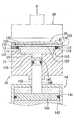
図2,3,及び4を参照すると、本発明に従った均等プレス装置の第1の望ましい実施例は、対向する上部表面及び下部表面110,120を有する基盤100上においてマイクロナノ製造工程を実行するよう使用される。均等プレス装置は、下方プレスユニット10、上方プレスユニット20、及びモールド30を有する。 Referring to FIGS. 2, 3, and 4, a first preferred embodiment of a uniform press apparatus according to the present invention performs a micro-nano fabrication process on a
下方プレスユニット10は、支持容器11、均圧液体12、密封部材13、及び加圧機器14を有する。 The
支持容器11は、上方向に開放する収容空間111、収容空間111の上方端部を画定し且つ基板100の下部表面120に対して終端する環状上部表面112、上部表面112の下方に配置される環状取付け表面113、及び、上部表面112の内周と取付け表面113の外周との間で接続される円筒形の肩部表面114を有する。収容空間111の上方端部は、基板100によって密封される。収容空間111は、円形の断面、基板100に隣接する大口径部115、及び加圧機器14に近接し且つ大口径部115の直径より小さい直径を有する小口径部116を有する。大口径部115は、基板100と小口径部116との間において配置される。 The
均圧液体12は、支持容器11における収容空間111内で受けられる。 The
密封部材13は、環状取付け表面113と基板100の下部表面120との間においてクランプされ、また、環状取付け表面113上に配置され且つ肩部表面114と接触する金属密封リング、及び環状取付け表面113上に配置されるゴム密封リング132を有する。金属密封リング131は、その内周に沿って内方向に開放する環状溝133を有する。ゴム密封リング132は、金属密封リング131において溝133と係合する。この実施例において、金属密封リング131は、銅とベリリウムとの合金等である銅合金を有して作られる。 The sealing
加圧機器14は、シリンダ141、収容空間111の小口径部116へと延在するピストン部材142、及びシリンダ141内で受けられる圧縮液体143を有する。ピストン部材142は、軸方向(X)に沿ってシリンダ141及び支持容器11に対して可動である。ピストン部材142は、シリンダ141において可動に配置される大口径ヘッド144、小口径部116において可動に配置され且つ大口径ピストンヘッド144の直径より小さい直径を有する小口径ピストンヘッド145、及び、大口径ピストンヘッド及び小口径ピストンヘッド144,145を固定的に相互接続し且つ軸方向(X)に沿って延在する接続部146を有する。この実施例において、加圧機器14は、油圧ポンプ等である圧力源(図示せず)に対して接続される。圧力源は、大口径ピストンヘッド144を動かすために圧縮液体143を駆動するよう操作可能であり、小口径ピストンヘッド145は、軸方向(X)に沿って動かされ、それによって均圧液体12を圧迫する。 The pressurizing
モールド30は、基板100の上部表面110上に配置され、基板100の上部表面110に面する形成表面31を有する。 The
上部プレスユニット20は、下方プレスユニット10のすぐ上方に配置され、モールド30に接触するよう軸方向(X)に沿って支持容器11に対して可動である。上方プレスユニット20は、既知の方途においてモールド30及び基板100を加熱又は冷却することができる。 The
上方プレスユニット20がモールド30に接触するようになる際、上方プレスユニット20は停止され、また、圧力源は、図3に示される通り、自動制御下で均圧液体12に対して小口径ピストンロッド145を動かし且つプレスするよう作動される。したがって、均等上方向圧力は、モールド30の形成表面31に対して基板100の上部表面110をプレスするよう適用される。結果として、凹状形状は、図4に示される通り、基板100の上部表面110上に形成される。 When the
上述によれば、本発明の均等プレス装置は、以下の利点を有する:
(1)均圧液体12は、上述された先行技術において利用されるフィルムの代りに、基板100に接触し且つ基板100対して直接プレスするよう使用される。故に、本発明の均等プレス装置は、より耐久性があり且つ安価である。
(2)大口径ピストンヘッド144の断面積が小口径ピストンヘッド145の断面積より大きいため、小口径ヘッド145によって生成される均圧液体12に対する押付け力は、圧縮液体145によって大口径ピストンヘッド145に対して適用されるものの数倍である。したがって、圧力源に対して求められる出力は、大幅に低減され得る。言い換えれば、たとえ基板100が金属薄板であるとしても、本発明の均等プレス装置は、基板100の上部表面110上において完全なインプリント作業を行なうよう十分な圧力を与え得る。According to the above, the equal press apparatus of the present invention has the following advantages:
(1) The
(2) Since the cross-sectional area of the large-
あるいは、モールド30は、上方プレスユニット20の下部表面に対して固定的に取り付けられ得る。かかる代替的な構造を有して、自動制御下において、上方プレスユニット20の下方向運動中、モールド30が基板100に接触する際、上方プレスユニット20は停止される。 Alternatively, the
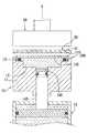
図5は、構造上は第1の望ましい実施例に類似する本発明に従った均等プレス装置の第2の望ましい実施例を示す。第1の望ましい実施例とは対照的に、シリンダ141は、支持容器11に接触し且つそれに対して固定的に取り付けられ、肩部表面114は、裁頭円錐形であり、金属密封リング131は、肩部表面114上に配置される。この実施例において、肩部表面114は、環状上部表面112の内周から取付け表面113の外周まで内方向及び下方向に延在する。金属密封リング131は、ゴム密封リング132と接触する環状内周表面134を有する。 FIG. 5 shows a second preferred embodiment of a uniform press apparatus according to the present invention that is structurally similar to the first preferred embodiment. In contrast to the first preferred embodiment, the
1 支持ユニット
2 モールド
3 ホルダ
4 駆動ユニット
5 均等プレス部材
6 基板
10 下方加圧ユニット
11 支持容器
12 均圧液体
13 密封部材
14 加圧機器
31 成形表面
100 基板
110 上部表面
111 収容空間
112 環状上部表面
113 環状取付け表面
114 肩部表面
115 大口径ピストン
116 小口径ピストン
120 下部表面
131 金属密封リング
132 ゴム密封リング
133 溝
134 環状内周表面
141 シリンダ
142 ピストン部材
143 圧縮液体
144 大口径ピストンヘッド
145 小口径ピストンヘッド
146 接続部
501 弾性フィルム
502 流体
X 軸方向DESCRIPTION OF
Claims (6)
Translated fromJapanese支持容器、均圧液体、及び加圧機器を有する、下方プレスユニットと、
該下方プレスユニットのすぐ上方に配置され、該下方プレスユニットの前記支持容器に対して可動である、上方プレスユニットと、
前記基板の前記上部表面上に配置されるよう適合され、前記基板の前記上部表面が前記下方プレスユニットによってプレスされるよう適合される成形表面を有する、モールドと、
によって特徴付けられ、
前記支持容器は、上方向に開放する収容空間と、該収容空間の上方端部を画定し、且つ該収容空間の上方端部が前記基板によって密封されるよう前記基板の前記下部表面に対して終端するよう適合される環状上部表面と、を有し、
前記均圧液体は、前記支持容器における前記収容空間内において受けられ、
前記加圧機器は、ピストン部材を有し、該ピストン部材は、前記支持容器における前記収容空間へと延在し且つ前記均圧液体を軸方向において上向きに押すよう作動可能である、
均等プレス装置。An equal press apparatus adapted to perform a nanoimprint operation on a substrate having opposing upper and lower surfaces comprising:
A lower press unit having a support container, a pressure equalizing liquid, and a pressurizing device;
An upper press unit disposed immediately above the lower press unit and movable relative to the support container of the lower press unit;
A mold having a molding surface adapted to be disposed on the upper surface of the substrate, the upper surface of the substrate being adapted to be pressed by the lower press unit;
Is characterized by
The support container defines an accommodating space that opens upward, and an upper end of the accommodating space, and the upper end of the accommodating space is sealed by the substrate with respect to the lower surface of the substrate. An annular top surface adapted to terminate, and
The pressure equalizing liquid is received in the accommodating space in the support container,
The pressurizing device has a piston member, the piston member extends to the receiving space in the support container and is operable to push the pressure equalizing liquid upward in the axial direction.
Equal press device.
前記下方プレスユニットは更に、前記環状取付け表面上に配置される密封部材を有し、
該密封部材は、前記環状取付け表面上に配置され且つ前記肩部表面に接触する金属密封リングと、前記環状取付け表面上に配置されるゴム密封リングと、を有し、
前記金属密封リングは、その内周に沿って内方向に開放する環状溝を有し、前記ゴム密封リングは、前記金属密封リングにおける前記溝に係合する、
請求項1記載の均等プレス装置。The support container further includes an annular mounting surface disposed below the annular upper surface, and a cylindrical shoulder surface connected between an inner periphery of the annular upper surface and an outer periphery of the annular mounting surface. Have
The lower pressing unit further comprises a sealing member disposed on the annular mounting surface;
The sealing member includes a metal sealing ring disposed on the annular mounting surface and contacting the shoulder surface; and a rubber sealing ring disposed on the annular mounting surface;
The metal sealing ring has an annular groove that opens inward along its inner periphery, and the rubber sealing ring engages the groove in the metal sealing ring;
The equal press apparatus of Claim 1.
前記下方プレスユニットは更に、密封部材を有し、
該密封部材は、前記肩部表面上に配置される金属密封リングと、前記環状取付け表面上に配置されるゴム密封リングと、を有し、
前記金属密封リングは、前記ゴム密封リングと接触する環状内周表面を有する、
ことを特徴とする請求項1記載の均等プレス装置。The support container further includes an annular mounting surface disposed below the annular upper surface, and a truncated cone extending inwardly and downwardly from an inner periphery of the annular upper surface to an outer periphery of the annular mounting surface. A shoulder surface, and
The lower press unit further includes a sealing member,
The sealing member includes a metal sealing ring disposed on the shoulder surface and a rubber sealing ring disposed on the annular mounting surface;
The metal sealing ring has an annular inner peripheral surface that contacts the rubber sealing ring;
The equal pressing apparatus according to claim 1.
前記加圧機器の前記ピストン部材は、前記収容空間の前記小口径部へと延在する、
ことを特徴とする請求項1記載の均等プレス装置。The receiving space in the support container has a circular cross section, a small diameter portion, a diameter larger than the diameter of the small diameter portion, and is adapted to be positioned between the substrate and the small diameter portion. A large-diameter portion,
The piston member of the pressurizing device extends to the small-diameter portion of the accommodation space;
The equal pressing apparatus according to claim 1.
前記ピストン部材は、前記軸方向において前記シリンダに対して可動であり、且つ前記シリンダにおいて可動に配置される大口径ピストンヘッドと、前記収容空間の前記小口径部において可動に配置され、且つ前記大口径ピストンヘッドの直径より小さい直径を有する小口径ピストンヘッドと、を有する、
ことを更に特徴とする請求項4記載の均等プレス装置。The pressurizing device further comprises a cylinder and a compressed liquid received in the cylinder,
The piston member is movable with respect to the cylinder in the axial direction and is movably disposed in the small-diameter portion of the housing space, and is movably disposed in the cylinder, A small bore piston head having a diameter smaller than the diameter of the bore piston head,
The equal press apparatus according to claim 4, further characterized in that:
ことを更に特徴とする請求項5記載の均等プレス装置。The piston member further includes a connecting portion that fixedly interconnects the large-diameter piston head and the small-diameter piston head.
The equal press apparatus according to claim 5, further characterized by the above.
Priority Applications (1)
| Application Number | Priority Date | Filing Date | Title |
|---|---|---|---|
| JP2008311683AJP4907638B2 (en) | 2008-12-08 | 2008-12-08 | Equal press machine used in micro-nanoimprint process |
Applications Claiming Priority (1)
| Application Number | Priority Date | Filing Date | Title |
|---|---|---|---|
| JP2008311683AJP4907638B2 (en) | 2008-12-08 | 2008-12-08 | Equal press machine used in micro-nanoimprint process |
Publications (2)
| Publication Number | Publication Date |
|---|---|
| JP2010131923A JP2010131923A (en) | 2010-06-17 |
| JP4907638B2true JP4907638B2 (en) | 2012-04-04 |
Family
ID=42343743
Family Applications (1)
| Application Number | Title | Priority Date | Filing Date |
|---|---|---|---|
| JP2008311683AExpired - Fee RelatedJP4907638B2 (en) | 2008-12-08 | 2008-12-08 | Equal press machine used in micro-nanoimprint process |
Country Status (1)
| Country | Link |
|---|---|
| JP (1) | JP4907638B2 (en) |
Families Citing this family (3)
| Publication number | Priority date | Publication date | Assignee | Title |
|---|---|---|---|---|
| TWI400160B (en) | 2010-11-18 | 2013-07-01 | Univ Nat Taiwan Science Tech | A micro/nano-imprint mold of the fabricating process |
| TWI409161B (en)* | 2010-12-10 | 2013-09-21 | Chenming Mold Ind Corp | Mold device with uniform pressure and molding method thereof |
| JP5384709B2 (en)* | 2012-07-25 | 2014-01-08 | コマツ産機株式会社 | Die set |
Family Cites Families (5)
| Publication number | Priority date | Publication date | Assignee | Title |
|---|---|---|---|---|
| JPS5160255A (en)* | 1974-11-25 | 1976-05-26 | Nissha Printing | NETSUKASOSEIJUSHISHIITONI OOTOTSUOTSUKERUHOHO |
| JP3580986B2 (en)* | 1996-07-24 | 2004-10-27 | 日機装株式会社 | Press forming equipment |
| JP3367518B2 (en)* | 1999-12-09 | 2003-01-14 | 日本電気株式会社 | Mold and method for forming partition of display panel using the same |
| SE515607C2 (en)* | 1999-12-10 | 2001-09-10 | Obducat Ab | Device and method for fabrication of structures |
| JP4447522B2 (en)* | 2005-07-06 | 2010-04-07 | 株式会社日立産機システム | Fine shape molded product manufacturing apparatus and manufacturing method thereof |
- 2008
- 2008-12-08JPJP2008311683Apatent/JP4907638B2/ennot_activeExpired - Fee Related
Also Published As
| Publication number | Publication date |
|---|---|
| JP2010131923A (en) | 2010-06-17 |
Similar Documents
| Publication | Publication Date | Title |
|---|---|---|
| TWI663634B (en) | Bonding equipment | |
| JP4907638B2 (en) | Equal press machine used in micro-nanoimprint process | |
| JP2012505082A (en) | Method and apparatus for forming can body | |
| CN205749083U (en) | The cold inlaying device of novel metallographic specimen | |
| TWI536481B (en) | Device for filling metal | |
| CN110328278B (en) | Large thin-wall curved surface part forming device and method | |
| CN204413445U (en) | Middle plate welding fixture | |
| JP5054412B2 (en) | Hot press molding apparatus and mold system for the same | |
| CN107107425B (en) | Closing unit of injection molding machine with strut | |
| CN104889763A (en) | Pressure-assistant thin-wall blank precise processing method | |
| CN111745029A (en) | Method and device for forming curved surface parts with radial difference in thickness | |
| US7462029B1 (en) | Uniform pressing apparatus for use in a micro-nano imprint process | |
| CN111089710A (en) | Tubular part structural strength hydrostatic test device | |
| CN101673628A (en) | Clamp for one-step seal-exhaust of vacuum arc chute | |
| EP2194428A1 (en) | Uniform pressing apparatus for use in a micro-nano imprint process | |
| JP2011143531A (en) | Clamp device | |
| JP5131963B2 (en) | Vibration welding equipment | |
| CN106312345B (en) | It is a kind of to apply prestressed device | |
| TWI787850B (en) | Molding equipment and molding method | |
| JP5748728B2 (en) | Pressure forming device | |
| TWI337371B (en) | ||
| CN107884260A (en) | A kind of method of material property under measurement high-temperature and high-pressure conditions | |
| JPWO2013008759A1 (en) | Fluid pressure imprint apparatus provided with a pressurizing part fixture | |
| CN102728722A (en) | Stamping mould of water level sensor | |
| JP2004071717A (en) | High pressure processor |
Legal Events
| Date | Code | Title | Description |
|---|---|---|---|
| A977 | Report on retrieval | Free format text:JAPANESE INTERMEDIATE CODE: A971007 Effective date:20111209 | |
| TRDD | Decision of grant or rejection written | ||
| A01 | Written decision to grant a patent or to grant a registration (utility model) | Free format text:JAPANESE INTERMEDIATE CODE: A01 Effective date:20111220 | |
| A01 | Written decision to grant a patent or to grant a registration (utility model) | Free format text:JAPANESE INTERMEDIATE CODE: A01 | |
| A61 | First payment of annual fees (during grant procedure) | Free format text:JAPANESE INTERMEDIATE CODE: A61 Effective date:20120111 | |
| FPAY | Renewal fee payment (event date is renewal date of database) | Free format text:PAYMENT UNTIL: 20150120 Year of fee payment:3 | |
| R150 | Certificate of patent or registration of utility model | Free format text:JAPANESE INTERMEDIATE CODE: R150 | |
| LAPS | Cancellation because of no payment of annual fees |