JP4902575B2 - Road sign recognition device and road sign recognition method - Google Patents
Road sign recognition device and road sign recognition methodDownload PDFInfo
- Publication number
- JP4902575B2 JP4902575B2JP2008046617AJP2008046617AJP4902575B2JP 4902575 B2JP4902575 B2JP 4902575B2JP 2008046617 AJP2008046617 AJP 2008046617AJP 2008046617 AJP2008046617 AJP 2008046617AJP 4902575 B2JP4902575 B2JP 4902575B2
- Authority
- JP
- Japan
- Prior art keywords
- image
- road
- road marking
- information
- template
- Prior art date
- Legal status (The legal status is an assumption and is not a legal conclusion. Google has not performed a legal analysis and makes no representation as to the accuracy of the status listed.)
- Expired - Fee Related
Links
Images


Classifications
- G—PHYSICS
- G01—MEASURING; TESTING
- G01C—MEASURING DISTANCES, LEVELS OR BEARINGS; SURVEYING; NAVIGATION; GYROSCOPIC INSTRUMENTS; PHOTOGRAMMETRY OR VIDEOGRAMMETRY
- G01C21/00—Navigation; Navigational instruments not provided for in groups G01C1/00 - G01C19/00
- G01C21/26—Navigation; Navigational instruments not provided for in groups G01C1/00 - G01C19/00 specially adapted for navigation in a road network
- G—PHYSICS
- G06—COMPUTING OR CALCULATING; COUNTING
- G06V—IMAGE OR VIDEO RECOGNITION OR UNDERSTANDING
- G06V20/00—Scenes; Scene-specific elements
- G06V20/50—Context or environment of the image
- G06V20/56—Context or environment of the image exterior to a vehicle by using sensors mounted on the vehicle
- G06V20/588—Recognition of the road, e.g. of lane markings; Recognition of the vehicle driving pattern in relation to the road
Landscapes
- Engineering & Computer Science (AREA)
- Radar, Positioning & Navigation (AREA)
- Remote Sensing (AREA)
- Physics & Mathematics (AREA)
- General Physics & Mathematics (AREA)
- Multimedia (AREA)
- Theoretical Computer Science (AREA)
- Automation & Control Theory (AREA)
- Traffic Control Systems (AREA)
- Image Analysis (AREA)
- Image Processing (AREA)
- Navigation (AREA)
Description
Translated fromJapanese本発明は、画像を用いて道路標示を検出する技術に関する。 The present invention relates to a technique for detecting a road sign using an image.
自車両に搭載された撮像装置が撮像した画像から道路標示を検出し、ナビゲーションの情報を最新のものに更新することで、正確な協調を可能とするような技術が知られている。 A technique is known that enables accurate cooperation by detecting road markings from an image captured by an imaging device mounted on the host vehicle and updating navigation information to the latest information.
例えば、引用文献1に記載された発明のように、道路標示の記号列または文字列を部分的に検出して、撮像画像上における残りの記号または文字の位置を相対的に判断し、画像の処理領域を設定するような技術が知られている。
しかしながら、特許文献1に記載の技術では、判断することが可能な記号または文字の位置は、現在の撮像画像上に含まれているものに限られ、残りの道路標示が撮像画像上に無かった場合や、ペイントがかすれている場合には、これらを認識することは困難である。また、外乱に弱く、影等により生じる撮像画像上の輝度差を、道路標示と誤認してしまう可能性もある。 However, in the technique described in
そこで本発明では、カメラによって撮像される画像を蓄積し、現在の撮像画像に含まれていない道路標示についても、予測される道路標示の組み合わせに基づいて確実に識別することが可能な技術を提供することを目的とする。 Therefore, the present invention provides a technique capable of accumulating images captured by a camera and reliably identifying road markings not included in the current captured image based on a combination of predicted road markings. The purpose is to do.
前記課題を解決するための本発明の道路標示認識装置は、蓄積画像中に含まれる道路標示を、予測される組み合わせに基づいて精度良く識別することが可能な技術を提供する。
例えば、複数の撮像画像を垂直方向から見下ろす画像に変換して時系列順に接続し、合成画像を生成する画像生成手段と、前記撮像画像に含まれている道路標示の種別を、周辺の連続する組み合わせの道路標示に応じた特徴量の要素を含む周辺情報から識別する道路標示判断手段と、を備え、前記道路標示判断手段は、前記周辺情報に含まれる特徴量の要素と、前記合成画像の特徴量の要素と、の相関値を求め、前記相関値が所定の値以上であった場合に、前記周辺情報から、前記撮像画像に含まれている連続する組み合わせの道路標示の種別を識別することを特徴とする。
The road marking recognition apparatus of the present invention for solving the above problems provides a technique capable of accurately identifying road markings included in an accumulated image based on a predicted combination.
For example, a plurality of captured images are converted into images looking down from the vertical direction, connected in time series order, and a composite image is generated, andthe types of road markings included in the captured images are consecutive in the vicinity. Road marking judgment means for discriminating from peripheral information including feature quantity elements corresponding to a combination road sign, wherein the road marking judgment means includes the feature quantity elements included in the peripheral information, and the composite image A correlation value between the feature quantity elements is obtained, and when the correlation value is equal to or greater than a predetermined value, the types of road signs of consecutive combinations included in the captured image are identified from the peripheral information. It is characterized by that.
以下、本発明を実施するための最良の形態について、図面を参照して説明する。 The best mode for carrying out the present invention will be described below with reference to the drawings.
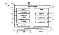
図1は、本願の第一の実施形態にかかる道路標示認識システム100の機能構成を示すブロック図である。 FIG. 1 is a block diagram showing a functional configuration of a road
図示するように、道路標示認識システム100は、道路標示認識装置10と、カーナビゲーション装置80と、車載カメラ99と、を含んでいる。 As illustrated, the road
道路標示認識装置10は、記憶部110と、制御部120と、インターフェース部130(以下、I/F部と称する)と、を備える。 The road
記憶部110は、画像記憶領域111と、変換テーブル記憶領域112と、識別テーブル記憶領域113と、を有する。 The
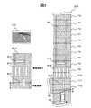
画像記憶領域111は、カメラから取得したフレーム画像と、画像生成部121がフレーム画像から生成する俯瞰画像およびモザイク画像と、を記憶する。図2に、画像記憶領域111の記憶するフレーム画像900と、俯瞰画像910と、モザイク画像920と、の概略図を示す。 The image storage area 111 stores a frame image acquired from the camera, and an overhead image and a mosaic image generated from the frame image by the
変換テーブル記憶領域112は、実画像(フレーム画像900)から俯瞰画像910を生成するために必要な変換テーブル(図示しない)を記憶する。変換テーブルとは、例えば、フレーム画像900の各画素の座標位置と、俯瞰画像910の各画素の座標位置と、を対応付け、ここに角度差やレンズの歪曲収差を補正するための補正パラメータを配したものである。これらはレンズの光学特性並びに自車両90に対する取り付け位置及び角度に基づいて、一意に決定される。なお、変換テーブルは、I/F部を介して、他の装置から取得してもよい。 The conversion table storage area 112 stores a conversion table (not shown) necessary for generating the
識別テーブル記憶領域113は、2つ以上の組み合わせからなる道路標示を特定するための基準として、図3に示すような識別テーブル1131を予め記憶する。 The identification
具体的に、識別テーブル1131は、2つ以上の組み合わせの道路標示について、それぞれの種別を特定するための種別情報13eを有する。種別情報13eは、例えば、自車両に近い側の道路標示から順に、種別情報A、種別情報B・・・(以下、道路標示の数だけ続く)を示す情報である。 Specifically, the identification table 1131 has
さらに、識別テーブル1131は、上記組み合わせからなる道路標示の特徴量として、縦方向輝度投影パターン13aと、横方向輝度投影パターン13bと、縦方向エッジパターン13cと、横方向エッジパターン13dと、を格納する。ここでは、以上4つの要素からなる特徴量を、テンプレート13と称する。 Furthermore, the identification table 1131 stores the vertical direction
なお、識別テーブル1131は、I/F部を介して、他の装置から取得する構成としてもよい。 The identification table 1131 may be obtained from another device via the I / F unit.
制御部120は、画像生成部121と、道路標示判断部122と、位置情報生成部123と、を有する。 The
画像生成部121は、撮像された車両後方の実画像(フレーム画像900)から、過去に撮像した画像を一枚にまとめたモザイク画像920を生成する。より具体的には、画像生成部121は、まず、車載カメラ99の撮像する画像から、フレーム画像900を取得して、これを画像記憶部111に時系列順に蓄積する。次に、画像生成部121は、フレーム画像900を垂直方向から見下ろした俯瞰画像(天空から地上面を見た場合の平面図)910を生成し、過去に合成されたモザイク画像920に、最新の俯瞰画像910を接続するモザイキング処理を施す。モザイキング処理とは、連続的に入力された画像から得られる複数の画像を繋ぎ合わせて、1枚のモザイク画像を作成する処理である。詳細は後述する。 The
なお、フレーム画像900は、車載カメラ99のフレームレートに従って撮像されるが、例えば、フレームレートが車速によって変化し、常に一定の距離範囲を撮像したフレーム画像900を得るような構成としてもよい。また、フレームレートに関わらず、一定の距離間隔ごとに、これを取得してもよい。 Note that the
道路標示判断部122は、モザイク画像920から特徴量を抽出して、画像中に道路標示が含まれているか否かを判断する。具体的には、道路標示判断部122は、モザイク画像920に対して、特徴量抽出処理を実行する。特徴量の抽出処理は、例えば、モザイク画像920の縦方向と横方向とに対して、輝度投影処理およびエッジ抽出処理を実行し、特徴量の各要素を抽出するものである。また、道路標示判断部122は、抽出した特徴量と、テンプレート13とを照合するテンプレートマッチングを実行して、モザイク画像920に含まれる道路標示を識別する。 The road
位置情報生成部123は、モザイク画像920に含まれる道路標示に関する位置情報を生成して、I/F部130を介してカーナビゲーション装置80へと出力する。位置情報には、例えば、道路標示の種別や、自車両からの距離、角度等の情報が含まれる。 The position
I/F部130は、カーナビゲーション装置80と通信を行うためのインターフェースである。通信方式には、どのような手段を利用してもよい。また、道路標示認識装置10と、カーナビゲーション装置80とが、同一機器である一体型としてもよい。 The I /
カーナビゲーション装置80は、例えば、GPS(全地球測位システム)や車速パルス、ジャイロなどの自律航法装置を利用して、自車両の位置の検出や、目的地への走行経路案内を実行する装置である。また、本実施形態にかかるカーナビゲーション装置80は、位置情報生成部123から出力される道路標示に関する位置情報に協調して、自車位置を補正することが可能である。 The
車載カメラ99は、例えば、車両の後方に設置され、車両後方側の所定の撮影範囲を、地面に対して斜めに見下ろす方向で撮像する。もちろん、設置位置は車両の後方に限らず、車両の前方や車体下等に設置することも可能である。 The in-
ここで、道路標示認識装置10のハードウェア構成について説明する。図13は、道路標示認識装置10の電気的な構成を示すブロック図である。 Here, the hardware configuration of the road
図13に示すように、道路標示認識装置10は、コンピュータの主要部であって、各装置を集中的に制御するCPU(Central Processing Unit)1と、各種データを書換え可能に記憶するメモリ2と、を備える。さらに、道路標示認識装置10は、各種のプログラム、プログラムが生成するデータ等を格納する外部記憶装置3と、外部の装置と通信を行う通信装置4と、を備える。これらの各装置は、バスなどの信号線5を介してCPU1と接続される。 As shown in FIG. 13, a road
CPU1は、例えば、外部記憶装置3上に格納されたプログラムをメモリ2上にロードして実行することにより、各種処理を実行する。 The
外部記憶装置3は、例えばHDD(Hard Disk Drive)を備えているが、もちろん、HDDのみに限定されず、配布されたプログラムであるコンピュータソフトウェアや、データを読み取るための機構として、CD−ROM、DVD−ROM等のドライブをさらに備えてもよい。 The external storage device 3 includes, for example, an HDD (Hard Disk Drive), but is not limited to the HDD. Of course, the external storage device 3 is not limited to the HDD, and is a computer program that is a distributed program, a CD-ROM, a mechanism for reading data, A drive such as a DVD-ROM may be further provided.
以上のように構成される道路標示認識装置10での処理について、図4に示すフローチャートを用いて説明する。図4は、道路標示認識装置10が、実画像から位置情報を生成する際の処理の流れを示すフロー図である。 Processing in the road
画像生成部121は、まず、車載カメラ99の撮像画像を取得して、画像記憶領域111に蓄積する(S11)。具体的に、画像生成部121は、車載カメラ99から画像信号を取得すると、画像を構成するフレームを、フレーム画像900として画像記憶領域111に時系列順に格納する。 First, the
次に、画像生成部121は、フレーム画像900に俯瞰変換処理を施して、俯瞰画像910を生成する(S12)。具体的には、画像生成部121は、上述の変換テーブルに基づいて、フレーム画像900の各画素に対して、座標変換および補正を施し、俯瞰画像910を描画する。なお、俯瞰変換処理の方法は上述のものに限られず、どのような方法を用いてもよい。生成された俯瞰画像910は、画像記憶領域111に格納される。 Next, the
さらに、画像生成部121は、過去に合成されたモザイク画像に対してモザイキング処理を実行し、最新のモザイク画像を生成する(S13)。ここで、本実施形態にかかる画像生成部121の実行するモザイキング処理について、以下、図2および図5を参照して、具体的に説明する。 Further, the
図2に示すように、モザイク画像920は、一定の枚数(ここでは、12枚)の俯瞰画像910が、時系列順に次々と接続されたものである。従って、自車両90が図2に示すような位置にある場合、画像記憶領域111には、12枚の俯瞰画像910が接続されたモザイク画像920(P0−11)が格納されている。また、車載カメラ99は、道路標示「交差点」914、「横断歩道」913、「一時停止線」912を含む、最新のフレーム画像900を撮像している。 As shown in FIG. 2, the
ここで、図2に示すようなフレーム画像900から俯瞰画像910を生成した場合、生成された俯瞰画像910には、過去のモザイク画像920(P0−11)と重畳する領域である重複領域Dと、新規に接続される領域である対象領域Pと、が含まれる。そこで、画像生成部121は、対象領域Pの長さを一定以上に保証するために、以下のような処理を実行する。図5は、モザイキング処理の流れの概略を示すフロー図である。 Here, when the bird's-
画像生成部121は、まず、対象領域Pの移動方向(縦方向)の画素数Nを検出する(S131)。画素数Nは、例えば、フレームレート(数/s)、単位時間あたりの移動距離(m/s)、フレーム画像900の移動方向の画素数、移動方向への単位距離あたりの画素数(数/m)から算出することが可能である。なお、移動距離は、自車両90の車速センサ等の検出する走行速度を取得して算出すればよい。また、予め一定値の速度を設定し、基準の速度として使用することも可能である。 First, the
次に、画像生成部121は、画素数Nが所定の閾値T1以上か否かを判断する(S132)。閾値T1は、対象領域Pの大きさを決定するための任意の値である。具体的には、画像生成部121は、画素数Nが閾値T1以上であると判断した場合(S132でYES)、対象領域Pをモザイク画像920(P0−11)に接続して(S133)、最新のモザイク画像920(P1−12)を得る。さらに、画像生成部121は、画像記憶領域111のモザイク画像920(P0−11)を最新のモザイク画像920(P1−12)に更新して(S134)、道路標示判断部122に、特徴量の抽出処理を指示し、ステップ14へと進む。Next, the
画素数Nが閾値T1以上ではないと判断した場合には(S132でNO)、対象領域Pの縦方向の画素数が不足しているため、画像生成部121はステップ11に戻って処理を繰り返す。If the number of pixels N is determined not to be a threshold value above T1 (NO in S132), since the number of pixels in the vertical direction of the target area P is deficient, the
ステップ133における画像の接続方法としては、様々な方法が知られているが、例えば、文献「金澤靖、金谷健一、共著、“段階的マッチングによる画像モザイク生成”、電子情報通信学会論文誌、Vol.J86−DII,No.6,pp.816−824,2003.」に記載のような、段階的マッチング手法を用いることが可能である。 Various methods are known as an image connection method in
この手法では、まず、2画像の特徴点を抽出し、各点の近傍をテンプレートマッチングによって対応させる。その際、投票によって回転やスケール変化、射影的ひずみを段階的に推定し、テンプレート自身を変形させることによって、精度の高いモザイク画像を得ることが可能である。 In this method, first, feature points of two images are extracted, and the vicinity of each point is associated by template matching. At that time, it is possible to obtain a mosaic image with high accuracy by estimating rotation, scale change, and projective distortion step by step by voting and deforming the template itself.
図4に戻って、道路標示判断部122は、モザイク画像920に対して特徴量の抽出処理を実行する(S14)。具体的には、道路標示判断部122は、特徴量の抽出処理の指示を受け付けると、モザイク画像920の縦方向と横方向とに対して輝度投影処理とエッジ抽出処理と、を実行する。図6に、その具体例を示す。図6は、モザイク画像920の縦方向と横方向とについて、輝度投影処理およびエッジ抽出処理を実行した際の結果を示す概略図である。 Returning to FIG. 4, the road marking
輝度投影処理とは、例えば、モザイク画像920の各画素の輝度を縦方向並びに横方向に投影して、輝度投影量を検出するものである。この処理によって、道路標示判断部122は、図6に示すような縦方向輝度成分12aと横方向輝度成分12bとを、特徴量の要素として取得することができる。 In the luminance projection process, for example, the luminance of each pixel of the
エッジ抽出処理とは、例えば、モザイク画像920から濃淡が急に変化している領域を、その境界線によって抽出するものである。さらに、縦方向と横方向とのそれぞれのエッジ成分量を累積することで、道路標示判断部122は、縦方向エッジ成分12cと、横方向エッジ成分12dとを、特徴量の要素として得ることができる。 The edge extraction processing is, for example, extracting a region where the shading is abruptly changed from the
なお、抽出される特徴量の要素は、上記のものに限定されず、種々の画像成分の分布、強度、累積値等を用いることが可能である。 It should be noted that the extracted feature quantity elements are not limited to those described above, and various image component distributions, intensities, cumulative values, and the like can be used.
図4に戻って、道路標示判断部122は、テンプレートマッチングを実行する(S15)。具体的には、道路標示判断部122は、まず、上記で抽出したモザイク画像920の特徴量の、テンプレート13に対する要素ごとの相関値(類似度)を求める。次に、道路標示判断部122は、各相関値を所定の閾値T2と比較する。Returning to FIG. 4, the road marking
その結果、各要素の全ての相関値が閾値T2以上であるテンプレート13が検出された場合には(S15でYES)、位置情報生成部123に当該テンプレート13を含む適合レコードに関する情報を受け渡し、位置情報の生成を指示して、ステップ16へと進む。なお、複数のテンプレート13が検出された場合には、相関値が一番高いテンプレート13を含む適合レコードを受け渡す。全ての相関値が閾値T2以上であるテンプレートが検出されなかった場合には(S15でNO)、適合レコードなしと判断して、ステップ11へ戻って処理を繰り返す。As a result, if the
テンプレートマッチングにおける相関値の算出には、どのような手法を利用しても良く、例えば、ニューラルネットワークを用いたテンプレートマッチング法等の手法を用いることが可能である。また、テンプレートマッチング法に限らず、特徴空間における判別分析法等の、他の手法を用いてもよい。 Any method may be used for calculating the correlation value in the template matching. For example, a template matching method using a neural network may be used. In addition to the template matching method, other methods such as a discriminant analysis method in a feature space may be used.
なお、閾値T2は、テンプレートとの適合性を判断するために、各要素についてそれぞれ定められた値であり、任意の値を定めることが可能である。例えば、より低い値に設定することによって、道路標示がかすれていた場合でも、適合レコードの抽出が容易となる。また、全ての要素が閾値T2を満たさなくとも、一定数の要素が閾値以上であれば、適合するレコードとして判断してもよい。The threshold value T2 are, in order to determine the suitability of the template is a value determined respectively for each element, it is possible to define an arbitrary value. For example, by setting a lower value, it is easy to extract a matching record even when the road marking is faint. Also, without all of the elements satisfy the threshold T2, equal to or more than a certain number of elements threshold may be determined as a matching record.
さらに、位置情報生成部121は、モザイク画像920に含まれる道路標示の種別および自車両から最も近い道路標示までの距離、角度を検出して、位置情報を生成する(S16)。具体的には、位置情報生成部123は、位置情報の生成指示を受け付けると、適合レコードから種別情報13eを取得して、モザイク画像920に含まれる複数の道路標示のうち、自車両から最も近い道路標示の種別を識別する。そして、位置情報生成部123は、自車両から最も近い道路標示までの距離Sと、角度θと、を検出して、位置情報を生成する。 Furthermore, the position
かかる距離と角度との検出には、どのような手法を用いてもよいが、例えば、モザイク画像920に対してエッジ抽出処理を実行し、図2に示すように、道路標示の角や切れ目において、その形状の特徴を表わす特徴点を抽出することで、その結線から距離Sと、角度θと、を算出することが可能である。 Any method may be used for the detection of the distance and the angle. For example, edge extraction processing is executed on the
そして、位置情報生成部123は、生成した位置情報を、I/F部130を介してカーナビゲーション装置80へと出力し(S17)、処理を終了する。 Then, the position
以上、道路標示認識装置10が、実画像に含まれる道路表示の位置情報を生成する処理について説明した。上記フローによれば、蓄積した画像から特徴量を抽出し、その組み合わせに基づいたテンプレートマッチングを実行することで、過去に通過した路面上に存在する道路標示と、通過した直後の道路標示との前後関係から、精度良く道路標示を検出することができる。 In the above, the process in which the road
なお、識別テーブル1131に格納される道路標示は、どのような組み合わせであってもよい。例えば、{「横断歩道あり」と「停止線」}、{「停止線」と「横断歩道」}、{「横断歩道」と「交差点」}等の、高頻度の組み合わせのみを格納しておくことが可能である。このような構成によれば、誤認識の可能性をさらに低減できる。 The road markings stored in the identification table 1131 may be any combination. For example, store only high-frequency combinations such as {“with crosswalk” and “stop line”}, {“stop line” and “crosswalk”}, {“crosswalk” and “intersection”}, etc. It is possible. According to such a configuration, the possibility of erroneous recognition can be further reduced.
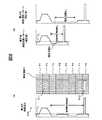
例えば、図7に示すように、影によって生じる線状の高輝度値の路面を含む領域400は、「停止線」と誤認される可能性がある。しかしながら、識別テーブル1131の記憶する道路標示の組み合わせに、上記のような高頻度の組み合わせのみが格納されていれば、テンプレートマッチングにおいて、頻度の低い連続する「停止線」に適合するレコードは検出されないため、これらが道路標示として認識されることはない。 For example, as shown in FIG. 7, a region 400 including a road surface with a linear high luminance value caused by a shadow may be mistaken as a “stop line”. However, if only the high-frequency combinations as described above are stored in the combinations of road markings stored in the identification table 1131, a record that matches a continuous “stop line” with low frequency is not detected in template matching. Therefore, these are not recognized as road markings.
なお、本発明は上記の実施形態に限定されるものではなく、その要旨の範囲内で様々な変形が可能である。
<変形例1>In addition, this invention is not limited to said embodiment, A various deformation | transformation is possible within the range of the summary.
<
例えば、上記実施形態では、モザイク画像920に対してテンプレートマッチングを実施していたが、これに限らず、モザイク画像920から一定の処理領域Rを抽出し、かかる処理領域に対してテンプレートマッチングを行ってもよい。このような変形例1について、以下に詳述する。図8(a)は、処理領域R(P1−P8)と、それに対応する横方向輝度成分22bの概略図である。 For example, in the above embodiment, template matching is performed on the
道路標示判断部122は、ステップ14において、画像生成部121からの特徴量の抽出指示を受け付けると、モザイク画像920から、自車両に最も近い2つの道路標示が含まれている領域を、処理領域Rとして抽出してもよい。なお、処理領域Rに含まれる道路標示の数は上記に限定されず、複数個であればいくつでもよい。 When the road marking
処理領域Rの抽出には、例えば、図8に示すように、横方向輝度成分22bから閾値T3以上の累積輝度値を有する領域を自車両側から2つ検出して、これらの領域を含む対象領域P(図8では、P1−P3、P8)と、その間の領域(P4−P7)とを、処理領域Rとして抽出する。閾値T3は、ここでは、車道外側線及び車道中央線の累積輝度値よりも若干大きな値が設定されているが、対象となる道路標示を検出可能であればどのような値を設定してもよい。The extraction process area R, for example, as shown in FIG. 8, a region having a
その後、道路標示判断部122は、処理領域Rに対して特徴量抽出処理を実行して、抽出した特徴量について、テンプレート13とのテンプレートマッチングを実行する。また、上記実施形態では、道路標示は一度のテンプレートマッチングで判断されていたが、本変形例によれば、1つの道路標示に対して複数回のテンプレートマッチングを実行することができる。以下、図2を用いて説明する。 Thereafter, the road marking
例えば、自車両90が、P0からP9の位置まで走行した場合、道路標示判断部122は、P1からP8を処理領域Rと定め、テンプレートマッチングによって、「横断歩道あり」911と、「一時停止線」912を識別する。ここで、道路標示判断部122は、直近の道路標示の種別「一時停止線」を記憶部110へ記憶させて、処理を終了する。 For example, when the
その後、自車両90がP11まで進行すると、道路標示判断部122は、P8からP10を処理領域Rと定め、テンプレートマッチングによって、「一時停止線」912と、「横断歩道」913を識別する。そこで、道路標示判断部122は、自車両から遠い側の道路標示の種別「一時停止線」を、記憶部110に格納される道路標示の種別と比較する。両者の種別が一致していれば、P8に存在する道路標示の種別を、「一時停止線」であると確定して、「一時停止線」912の位置情報の生成を、位置情報生成部123に指示する。 Thereafter, when the
このような構成によれば、モザイク画像の処理領域を限定することで、装置の負荷を軽減し、処理時間を短縮することが可能である。また、1つの道路標示に対して、複数回のテンプレートマッチングを実行することで、さらに高い精度の識別が可能である。
<変形例2>According to such a configuration, it is possible to reduce the load on the apparatus and shorten the processing time by limiting the processing region of the mosaic image. Further, it is possible to identify with higher accuracy by executing template matching a plurality of times for one road marking.
<
上記実施形態並びに変形例では、モザイク画像920(ならびにその処理領域R)に含まれる道路標示間の距離と、テンプレート13の示す特徴量の道路標示間の距離は、必ずしも一致しない。このような場合には、同じ組み合わせの道路標示であるにも関わらず適合レコードが検出されずに、マッチング精度が落ちてしまう可能性がある。 In the embodiment and the modification, the distance between the road markings included in the mosaic image 920 (and its processing region R) does not necessarily match the distance between the road markings of the feature amount indicated by the
もちろん、多様な道路標示間距離を有するテンプレートを備えていれば、精度のよいテンプレートマッチングを実行することが可能であるが、それには膨大な数のテンプレートが必要とされる。 Of course, if a template having various distances between road markings is provided, accurate template matching can be executed. However, a huge number of templates are required.
そこで、道路標示判断部122は、ステップ15において、テンプレートマッチングの結果、適合するレコードが無い場合には、テンプレート13を補正して、マッチングの精度を向上させるような処理を実行してもよい。以下、図8(a)に示すような処理領域R(P1−P8)に対するテンプレートマッチングの結果、適合レコードが無いと判断された場合を例として、具体的に説明する。 Therefore, in step 15, if there is no matching record as a result of template matching, the road marking
図8(b)は、道路標示が「横断歩道有り」と「停止線」を含む場合の、テンプレート13における補正前の横方向輝度投影パターンと、補正後の横方向輝度投影パターンと、の概略図である。 FIG. 8B shows an outline of the horizontal luminance projection pattern before correction and the horizontal luminance projection pattern after correction in the
道路標示判断部122は、テンプレートマッチングの結果、適合レコードが存在しなかった場合、処理領域Rに含まれる道路標示間の距離が、テンプレートマッチングの精度を欠く程度の大きさか否かを判断する。 When there is no matching record as a result of template matching, the road marking
具体的には、道路標示判断部122は、横方向輝度成分22bにおいて閾値T3以上の累積輝度値を有する領域間の距離S1を検出する。かかる距離が閾値T4以上であった場合、道路標示間距離S1により、テンプレートマッチング処理が精度を欠く可能性があると判断し、テンプレートの補正処理を実行する。閾値T4以上の長さでなかった場合には、最初の処理(フレーム画像取得処理)へ戻って、処理を繰り返す。More specifically, the road
次に、道路標示判断部122は、テンプレート13の横方向輝度投影パターン13bと、横方向エッジパターン13dとを、所定の補正位置Eで、縦方向に補正距離S2だけ補正する。なお、補正距離S2は、縦方向に画素を増加させてテンプレートを延長させるだけでなく、補正位置Eの周辺の画素を間引いて伸縮させてもよい。また、あらゆる道路標示間距離S1にマッチングするように、その値を段階的に設定することも出来る。また、テンプレート13から閾値T3以上の累積輝度値を有する領域間の距離S3を検出し、これを距離S1と同様の長さに補正してもよい。Then, the road
道路標示判断部122は、補正後のテンプレート13を用いて再度テンプレートマッチングを実行し、適合レコードが検出されれば、これを基に道路標示の種別を識別する。 The road marking
以上のような構成によれば、多様な道路標示間距離を有するテンプレートを必要とせずに、テンプレートマッチングの精度を向上させることが可能である。
<変形例3>According to the above configuration, it is possible to improve the template matching accuracy without requiring templates having various distances between road markings.
<Modification 3>
なお、上記実施形態および変形例では、識別テーブル1131は、2つ以上の組み合わせからなる道路標示ごとの情報を格納している。よって、道路標示認識装置10は、この組み合わせを基に道路標示を識別しているが、本発明はこれに限定されない。 In the above-described embodiment and the modification, the identification table 1131 stores information for each road marking composed of two or more combinations. Therefore, although the road marking
例えば、図9(a)に示すような、識別テーブル1141を有していてもよい。識別テーブル1141は、1つの道路標示ごとに、その特徴量であるテンプレート14を有する。さらに、記憶部110は、道路標示の組み合わせを自車両側から順に、種別情報A、種別情報Bとして格納する、図9(b)に示すような配列テーブル1151を予め記憶する。なお、配列テーブル1151に格納される種別情報は、2つの組み合わせに限らず、いくつの組み合わせを有していてもよい。 For example, you may have the identification table 1141 as shown to Fig.9 (a). The identification table 1141 has a
このような構成によれば、道路標示判断部122は、ステップ15において、モザイク画像920(処理領域R)に含まれる道路標示ごとに、テンプレート14とのテンプレートマッチングを実行する。 According to such a configuration, the road
例えば、図8(a)に示すような処理領域Rと、その特徴量とを抽出した場合では、横方向輝度成分22bにおいて閾値T3以上の領域を含む、対象領域P(図8では、P1−P3と、P8)のそれぞれについて、識別テーブル1141から適合レコードを抽出する。そして、道路標示判断部122は、適合レコードの種別情報A4eを取得して、各領域の道路標示が、「横断歩道あり」と、「一時停止線」であると判断する。For example, the processing region R as shown in FIG. 8 (a), in the case of extracting and its feature amount, in the transverse
次に、道路標示判断部122は、配列テーブル1151から、「一時停止線」−「横断歩道あり」の組み合わせの種別情報を有するレコードを検索する。レコードが存在すれば、道路標示判断部122は、P1−P3に存在する道路標示の種別を「横断歩道あり」、P8に存在する道路標示の種別を「一時停止線」であると確定して、「一時停止線」912の位置情報の生成を、位置情報生成部123に指示する。 Next, the road marking
なお、例えば、テンプレートマッチングの結果、かすれ等の理由で「一時停止線」の道路標示が判断できなかった場合、配列テーブル1151からもう一方の道路標示「横断歩道あり」が種別情報Bとして格納されているレコードを検出すれば、予想される組み合わせの道路標示を知ることが可能である。 Note that, for example, when the road marking of “temporary stop line” could not be determined due to fading or the like as a result of template matching, the other road marking “with pedestrian crossing” is stored as type information B from the array table 1151. It is possible to know an expected combination of road markings.
そこで、「一時停止線」を含む処理領域R(P8)に対して、今度は相関値との適合条件を緩和して(例えば、閾値T2の引き下げ等)、再度テンプレートマッチングを実行し、予想される組み合わせと合致する適合レコードが検出されれば、これを確定してもよい。Therefore, the processing region including the "stop line" R (P8), this time to relax the matching condition between the correlation values (e.g., reductions such threshold T2), to execute the template matching again expected If a matching record matching the combination to be detected is detected, this may be confirmed.
以上のような構成によれば、道路標示の一方が認識できなかったとしても、他の道路標示との組み合わせからその種別を予測することで、高確率の識別が可能となる。 According to the above configuration, even if one of the road markings cannot be recognized, it is possible to identify with high probability by predicting the type from the combination with other road markings.
次に、本発明の第二の実施形態にかかる道路標示認識装置20について説明する。第二の実施形態にかかる道路標示認識装置20によれば、自車両に備えられるセンサからの情報や、カーナビゲーション装置からの周辺に存在する道路標示に関する情報を用いて、テンプレートを絞り込み、より確実に正確な道路標示を識別することができる。以下、第一の実施形態と比較して、異なっている点について主に説明する。 Next, the road marking
図10は、道路標示認識システム200の、機能的な構成を示すブロック図である。 FIG. 10 is a block diagram showing a functional configuration of the road marking
図示するように、道路標示認識システム200は、道路標示認識装置20と、カーナビゲーション装置80と、自車両90と、車載カメラ99と、を含んでいる。 As illustrated, the road
カーナビゲーション装置80は、記憶部810と、制御部820と、I/F部830と、GPS受信部840と、を備える。 The
記憶部810は、地図データ811を記憶している。地図データ811は、例えば、ノードとリンクとから構成される地図情報である。ノードとは、交差点、車線数や幅員が変更する点であり、リンクとは、隣接するノードを連結するベクトルである。これらは、それぞれテーブルで管理され、一般的に、ノードテーブルには、ノードの座標、接続先のリンクID、幅員等の情報が、リンクテーブルには、接続先のノード、距離、方向、幅員等の情報が含まれる(図示しない)。ここで、本実施形態にかかる地図データ811の有するノードテーブルと、リンクテーブルとは、上記に加え、さらに、かかるノードおよびリンク中に存在する道路標示の座標を特定する位置情報と、道路標示の種別を特定する種別情報と、を有するものである。 The
制御部820は、道路標示認識装置20から、周辺情報の出力指示を受け付けると、図11に示すような、周辺情報8111を生成する。周辺情報8111は、自車両90の周辺に存在する道路標示の組み合わせと、それらの道路標示間の距離と、を特定する情報である。 When the control unit 820 receives a peripheral information output instruction from the road marking
具体的には、制御部820は、現在位置を中心として所定の範囲内に存在し、かつ、現在位置するノードおよびリンクから一繋がりの道路上に存在する道路標示を検出する。次に、隣り合う道路標示を、種別情報81a、種別情報81bとして組み合わせて格納し、組み合わせごとの道路標示間の距離を、道路標示間距離情報81cとして格納する。このようにして生成された周辺情報8111は、I/F部830を介して道路標示認識装置20へと出力される。 Specifically, the control unit 820 detects a road marking that exists in a predetermined range centered on the current position and that exists on a road that is connected to the current position from the node and link. Next, adjacent road markings are combined and stored as
I/F部830は、道路標示認識装置20と通信を行うためのインターフェースであり、どのような通信方式を利用してもよい。 The I /
GPS受信部840は、GPS(Global Positioning System)衛星からの信号を受信する。また、カーナビゲーション装置80は、この他に、道路に敷設されたビーコンや各地のFM放送局を介して、VICS(Vehicle Information and Communication System)センタから配信される道路交通情報を受信するVICS受信部等を備えていてもよい。 The
道路標示認識装置20は、記憶部210と、制御部220と、I/F部230と、を有する。 The road marking
記憶部210は、画像記憶領域211と、変換テーブル記憶領域212と、識別テーブル記憶領域213と、を有する。 The
画像記憶領域211、変換テーブル記憶領域212、識別テーブル記憶領域213とは、第一の実施形態にかかる画像記憶領域111、変換テーブル記憶領域112、識別テーブル記憶領域113と同様の構成であるため、詳細な説明を省略する。 The image storage area 211, the conversion
制御部220は、画像生成部221と、テンプレート補正部222と、道路標示判断部223と、位置情報生成部224と、を有する。 The
画像生成部221は、車載カメラ99からフレーム画像900を取得して、これを俯瞰画像910に変換する。さらに、画像生成部221は、自車両から、自車の走行状況に関する車両情報を取得して、これを基に俯瞰画像910からモザイク画像920を生成する。この具体的な処理は、後述する。 The
テンプレート補正部222は、自車の周辺にある道路標示に関する情報をカーナビゲーション装置から取得して、これに基づいてテンプレート13を補正する。具体的には、テンプレート補正部222は、周辺情報8111に含まれる種別情報と同様の組み合わせを有するレコードを、識別テーブル1131から抽出する。そして、周辺情報8111に含まれる道路標示間距離を基に、テンプレート13の横方向輝度投影パターン13bと横方向エッジパターン13dとを、延長および伸縮させて補正する。 The
道路標示判断部223は、モザイク画像から特徴量を抽出して、補正後のテンプレート13とテンプレートマッチングを行って、モザイク画像に含まれる道路標示の種別を判断する。 The road marking
位置情報生成部224は、モザイク画像に含まれる道路標示に関する位置情報を生成して、I/F部130を介してカーナビゲーション装置80へと出力する。 The position
自車両90は、制御部91と、速度センサ92と、操舵角センサ93と、角速度センサ94と、I/F部95と、を有する。 The
制御部91は、道路標示認識装置20からの車両情報出力指示を受け付けると、各センサから得た、自車両の走行速度、操舵角、角速度に関する情報を、車両情報として、I/F部95を介して道路標示認識装置20へと出力する。 When receiving the vehicle information output instruction from the road
速度センサ92は、自車両の走行速度を検出し、速度に応じた車速信号を出力する。速度センサ92は、車速を検出可能なセンサであればどのようなものでもよく、各車輪の回転数を検出する車輪速センサであってもよいし、車輪につながる車軸の回転数を検出する回転センサであってもよい。 The
操舵角センサ93は、運転者が入力した操舵角度の方向と大きさに応じた操舵角信号を出力する。検出される操舵角度は、例えば、自車両のステアリングホイールのゼロ点からの回転量及び回転方向である。 The
角速度センサ94は、ヨーイング(Yaw)方向の角速度、すなわち、ヨー角を検出する。角速度センサ94には、静電容量型、圧電型等、コリオリの力を応用したジャイロ型等のセンサが使用可能である。また、角速度センサ94は、さらに加速度を検出してもよい。 The
自車両90の有するセンサは、上述のものに限定されず、例えば地磁気センサ等の他のセンサをさらに有していてもよい。 The sensor of the
I/F部95は、道路標示認識装置20と通信を行うためのインターフェースである。 The I /
車載カメラ99は、第一の実施形態と同様の構成を有するため、詳細な説明は省略する。 Since the vehicle-mounted
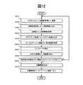
以上のように構成される道路標示認識装置20での処理について、図12に示すフローチャートを用いて説明する。図12は、本発明の第二の実施形態にかかる道路標示認識装置20が、実画像から位置情報を生成する際の処理の流れを示すフロー図である。 Processing in the road
画像生成部221は、まず、車載カメラ99の撮像する画像から、フレーム画像900を取得して、画像記憶領域111に蓄積する(S201)。 First, the
次に、画像生成部221は、フレーム画像900に俯瞰変換処理を施して、俯瞰画像910を生成する(S202)。 Next, the
続いて、画像生成部221は、自車両90に、車両情報の送信を指示して、車両情報を取得する(S203)。 Subsequently, the
自車両90は、車両情報の送信指示を受け付けると、各センサから得た、自車両の走行速度、操舵角、角速度に関する情報を、車両情報として、I/F部95を介して道路標示認識装置20へと出力する。 Upon receipt of the vehicle information transmission instruction, the
画像生成部221は、取得した車両情報に基づいてモザイキング処理を実行し、最新のモザイク画像を生成する(S204)。画像生成部221は、第一の実施形態と同様のモザイキング処理を実行するが、俯瞰画像910をモザイク画像920に接続する際(S133)に、車両情報を利用する点で異なる。 The
具体的には、画像生成部221は、例えば、取得した車両情報に含まれる走行速度から、ノイズ除去やエッジの強調等に関する処理の実行レベルを定めて画像の適正化処理を実行する。また、操舵角や角速度から、左右のずれや傾きを検出し、これを補正する処理を実行することも可能である。もちろん、車両情報の用途は上記に限定されず、さまざまな処理において利用可能である。そして、モザイク画像920を生成後、画像生成部221は、テンプレート補正部222に、テンプレート13の補正を指示する Specifically, for example, the
テンプレート補正部222は、カーナビゲーション装置に、周辺情報の送信を指示し、これを取得する(S205)。 The
カーナビゲーション装置80は、周辺情報の送信指示を受け付けると、周辺情報8111を生成する。生成された周辺情報8111は、I/F部830を介して道路標示認識装置20へと出力される。 When the
次に、テンプレート補正部222は、周辺情報に基づいて、テンプレート13を補正する(S206)。具体的には、テンプレート補正部222は、得られた周辺情報8111に含まれる種別情報81a、種別情報81bと同じ組み合わせ(順不同)を持つ種別情報13eを有するレコードを、識別テーブル1131から検出する。 Next, the
次に、テンプレート補正部222は、周辺情報8111に含まれる道路標示間距離情報81cに基づいて、検出されたレコードの横方向輝度投影パターン13bと、横方向エッジパターン13dとを、所定の補正位置Eで縦方向に延長および伸縮する補正処理を実行する。その後、テンプレート補正部222は、道路標示判断部223にモザイク画像920の特徴量の抽出を指示する。 Next, the
続いて、道路標示判断部223は、特徴量の抽出処理の指示を受け付けると、モザイク画像920に対して、特徴量の抽出処理を実行する(S207)。 Subsequently, when receiving an instruction for feature amount extraction processing, the road marking
次に、道路標示判断部223は、補正後のテンプレート13を用いて、モザイク画像920とのテンプレートマッチングを実行する(S208)。具体的には、道路標示判断部223は、まず、要素ごとの相関値(類似度)を求め、各相関値を所定の閾値T2と比較する。Next, the road marking
その結果、各要素の全ての相関値が閾値T2以上であるテンプレート13が検出された場合には(S208でYES)、位置情報生成部224に当該テンプレート13を含む適合レコードに関する情報を受け渡し、位置情報の生成を指示して、ステップ209へと進む。全ての相関値が閾値T2以上であるテンプレートが検出されなかった場合には(S208でNO)、適合レコードなしと判断して、ステップ201へ戻って処理を繰り返す。As a result, if the
位置情報生成部224は、モザイク画像に含まれる道路標示の種別および自車両から最も近い道路標示までの距離、角度を検出して、位置情報を生成する(S209。位置情報生成部224は、位置情報を、I/F部230を介してカーナビゲーション装置80へと出力して(S210)、処理を終了する。 The position
以上のような構成により、本実施形態にかかる道路標示認識装置20は、自車両に関する情報から、より高品質なモザイク画像を生成することが可能である。 With the configuration as described above, the road marking
さらに、周辺に存在する道路標示に関する情報をカーナビゲーション装置から取得して、テンプレートのさらなる絞り込みと、補正とを実行することで、より正確なテンプレートマッチングが可能となる。 Furthermore, by acquiring information related to road markings present in the vicinity from the car navigation device, and further narrowing down and correcting the template, more accurate template matching can be performed.
なお、周辺情報は、道路標示のサイズを特定する寸法情報を、種別情報に対応付けてさらに有していてもよい。このような構成により、テンプレート補正部222は、さらに詳細にテンプレートの特徴量を補正することが可能となる。 The peripheral information may further include dimension information that specifies the size of the road marking in association with the type information. With such a configuration, the
また、識別テーブル上で、地域ごとに特徴のある道路標示を管理し、カーナビゲーション装置から住所等の情報を取得して、地域性によってテンプレートをさらに絞り込んでもよい。 Further, on the identification table, a road sign having a characteristic for each region may be managed, information such as an address may be acquired from the car navigation device, and the template may be further narrowed down according to regional characteristics.
10・20・・・道路標示認識装置、80・・・カーナビゲーション装置、90・・・自車両、99・・・車載カメラ、110・210・・・記憶部、111・211・・・画像記憶領域、112・212・・・変換テーブル記憶領域、113・213・・・識別テーブル記憶領域、121、221・・・画像生成部、222・・・テンプレート補正部、122、223・・・道路標示判断部、123、224・・・位置情報判断部、130・・・インターフェース部。10.20 ... road marking recognition device, 80 ... car navigation device, 90 ... own vehicle, 99 ... in-vehicle camera, 110/210 ... storage unit, 111/211 ... image storage Area, 112, 212 ... Conversion table storage area, 113, 213 ... Identification table storage area, 121, 221 ... Image generation unit, 222 ... Template correction unit, 122, 223 ... Road marking Judgment part, 123, 224 ... Position information judgment part, 130 ... Interface part.
Claims (6)
Translated fromJapanese前記撮像画像に含まれている道路標示の種別を、周辺の連続する組み合わせの道路標示に応じた特徴量の要素を含む周辺情報から識別する道路標示判断手段と、を備え、
前記道路標示判断手段は、
前記周辺情報に含まれる特徴量の要素と、前記合成画像の特徴量の要素と、の相関値を求め、前記相関値が所定の値以上であった場合に、前記周辺情報から、前記撮像画像に含まれている連続する組み合わせの道路標示の種別を識別する
ことを特徴とする道路標示認識装置。An image generation means for converting a plurality of captured images into an image looking down from the vertical direction and connecting them in time series order to generate a composite image;
Road marking judgment means for identifying the type of road marking included in the captured image from surrounding information including a feature amount element according to a continuous combination of road markings in the vicinity, and
The road marking judgment means
A correlation value between the feature amount element included in the peripheral information and the feature amount element of the composite image is obtained, and when the correlation value is equal to or greater than a predetermined value, the captured image is obtained from the peripheral information. A road sign recognition apparatusfor identifying types of road signs in a continuous combination included in the .
前記周辺情報は、前記連続する組み合わせの道路標示間の距離と、各道路標示の寸法と、に関する情報をさらに含み、
前記周辺情報に格納される道路標示の特徴量の要素を、所定の補正位置において前記道路標示間の距離を伸縮させるよう補正する補正手段、をさらに備えている
ことを特徴とする道路標示認識装置。The road marking recognition device according to claim1 ,
The surrounding information further includes information on a distance between the consecutive combinations of road markings and dimensions of each road marking,
A road marking recognition apparatus, further comprising: a correction unit that corrects anelement of a characteristic amountof the road marking stored in theperipheral information so as to expand and contract a distance between the road markings at a predetermined correction position. .
さらに、前記識別された道路標示に対する自車両の相対位置を検出する位置検出手段、を備える
ことを特徴とする道路標示認識装置。The road marking recognition device according to claim1 or 2 ,
The road sign recognition apparatus further comprising position detection means for detecting a relative position of the host vehicle with respect to the identified road sign.
前記特徴量の要素は、前記合成画像の各画素の輝度を縦方向と横方向に投影して、取得された縦方向輝度成分と、横方向輝度成分と、である
ことを特徴とする道路標示認識装置。A road marking recognition device according to any one of claims 1to 3 ,
The feature amount element is a vertical luminance component and a horizontal luminance component obtained by projecting the luminance of each pixel of the composite image in the vertical direction and the horizontal direction. Recognition device.
前記特徴量の要素は、前記合成画像から濃淡が変化している縦方向及び横方向のエッジ成分から取得する、縦方向エッジ成分と、横方向エッジ成分と、である
ことを特徴とする道路標示認識装置。A road marking recognition device according to any one of claims1 to 4 ,
The feature quantity elements are a vertical edge component and a horizontal edge component acquired from vertical and horizontal edge components whose shades are changed from the composite image. Recognition device.
前記合成画像の特徴量の要素を抽出するステップと、
周辺の連続する組み合わせの道路標示に応じた特徴量の要素と、前記合成画像の特徴量の要素と、の相関値を求めるステップと、
前記相関値が所定の値以上であった場合に、前記撮像画像に含まれている連続する組み合わせの道路標示の種別を識別するステップと、を実行する
ことを特徴とする道路標示認識方法。Converting a plurality of captured images into an image looking down from the vertical direction and connecting them in chronological order to generate a composite image;
Extractingan element of a feature amount of the composite image;
Obtaining a correlation value between a feature value element corresponding to a road sign of a continuous combination of surroundings and a feature value element of the composite image;
And a step of identifying a continuous combination of road marking types included in the captured image when the correlation value is equal to or greater than a predetermined value .
Priority Applications (3)
| Application Number | Priority Date | Filing Date | Title |
|---|---|---|---|
| JP2008046617AJP4902575B2 (en) | 2008-02-27 | 2008-02-27 | Road sign recognition device and road sign recognition method |
| US12/370,073US20100040289A1 (en) | 2008-02-27 | 2009-02-12 | Load Sign Recognition Apparatus and Load Sign Recognition Method |
| EP09002437AEP2096575A2 (en) | 2008-02-27 | 2009-02-20 | Road sign recognition apparatus and road sign recognition method |
Applications Claiming Priority (1)
| Application Number | Priority Date | Filing Date | Title |
|---|---|---|---|
| JP2008046617AJP4902575B2 (en) | 2008-02-27 | 2008-02-27 | Road sign recognition device and road sign recognition method |
Publications (2)
| Publication Number | Publication Date |
|---|---|
| JP2009205403A JP2009205403A (en) | 2009-09-10 |
| JP4902575B2true JP4902575B2 (en) | 2012-03-21 |
Family
ID=40677695
Family Applications (1)
| Application Number | Title | Priority Date | Filing Date |
|---|---|---|---|
| JP2008046617AExpired - Fee RelatedJP4902575B2 (en) | 2008-02-27 | 2008-02-27 | Road sign recognition device and road sign recognition method |
Country Status (3)
| Country | Link |
|---|---|
| US (1) | US20100040289A1 (en) |
| EP (1) | EP2096575A2 (en) |
| JP (1) | JP4902575B2 (en) |
Families Citing this family (14)
| Publication number | Priority date | Publication date | Assignee | Title |
|---|---|---|---|---|
| JP5505729B2 (en)* | 2011-01-27 | 2014-05-28 | アイシン・エィ・ダブリュ株式会社 | Guide device, guide method, and guide program |
| JP5811666B2 (en)* | 2011-07-28 | 2015-11-11 | アイシン・エィ・ダブリュ株式会社 | Stop line detection system, stop line detection device, stop line detection method, and computer program |
| KR101428239B1 (en)* | 2012-12-04 | 2014-08-07 | 현대자동차주식회사 | Road marker recognition device and recognition method of the same |
| KR101393273B1 (en) | 2012-12-05 | 2014-05-09 | 이엔지정보기술 주식회사 | System for advanced road texture image |
| US10863111B2 (en) | 2016-10-26 | 2020-12-08 | Continental Automotive Gmbh | Method and system for generating a composed top-view image of a road |
| JP7001985B2 (en)* | 2016-12-16 | 2022-01-20 | パナソニックIpマネジメント株式会社 | Vehicle position estimation device, program, recording medium, and vehicle position estimation method |
| CN110309833B (en)* | 2018-03-20 | 2021-03-05 | 国家新闻出版广电总局广播电视规划院 | Method, equipment and computer-readable storage medium for image identification recognition |
| JP7179557B2 (en)* | 2018-09-27 | 2022-11-29 | 日立Astemo株式会社 | road sign recognition device |
| US11625851B2 (en) | 2018-10-30 | 2023-04-11 | Mitsubishi Electric Corporation | Geographic object detection apparatus and geographic object detection method |
| CN110991320B (en)* | 2019-11-29 | 2023-09-26 | 阿波罗智能技术(北京)有限公司 | Road condition detection method and device, electronic equipment and storage medium |
| JP7207359B2 (en) | 2020-04-06 | 2023-01-18 | トヨタ自動車株式会社 | Road area correction device, road area correction method and computer program for road area correction |
| JP7613406B2 (en) | 2022-04-01 | 2025-01-15 | トヨタ自動車株式会社 | Feature detection device, feature detection method, and feature detection computer program |
| CN114913407B (en)* | 2022-04-25 | 2025-04-11 | 四川省自贡运输机械集团股份有限公司 | A belt conveyor inspection robot positioning method and system |
| CN118230592B (en)* | 2024-05-21 | 2024-08-02 | 招商积余数字科技(深圳)有限公司 | Parking space management method and device for unattended parking lot and storage medium |
Family Cites Families (28)
| Publication number | Priority date | Publication date | Assignee | Title |
|---|---|---|---|---|
| US6091833A (en)* | 1996-08-28 | 2000-07-18 | Matsushita Electric Industrial Co., Ltd. | Local positioning apparatus, and a method therefor |
| CN1132750C (en)* | 1998-10-08 | 2003-12-31 | 松下电器产业株式会社 | Driving assisting device and recording medium |
| US6266442B1 (en)* | 1998-10-23 | 2001-07-24 | Facet Technology Corp. | Method and apparatus for identifying objects depicted in a videostream |
| JP2001101415A (en)* | 1999-09-29 | 2001-04-13 | Fujitsu Ten Ltd | Image recognizing device and image processor |
| JP2001134772A (en)* | 1999-11-04 | 2001-05-18 | Honda Motor Co Ltd | Object recognition device |
| JP4624594B2 (en)* | 2000-06-28 | 2011-02-02 | パナソニック株式会社 | Object recognition method and object recognition apparatus |
| JP4626054B2 (en)* | 2000-12-21 | 2011-02-02 | 日産自動車株式会社 | Vehicle travel control device |
| JP2003123197A (en)* | 2001-10-16 | 2003-04-25 | Alpine Electronics Inc | Road marking recognition device |
| US20040086153A1 (en)* | 2002-10-30 | 2004-05-06 | Yichang Tsai | Methods and systems for recognizing road signs in a digital image |
| JP4147470B2 (en)* | 2003-02-25 | 2008-09-10 | 日本精機株式会社 | Road surface display method and apparatus |
| JP4314870B2 (en)* | 2003-04-22 | 2009-08-19 | 日産自動車株式会社 | Lane detection device |
| JP4407920B2 (en)* | 2004-05-19 | 2010-02-03 | ダイハツ工業株式会社 | Obstacle recognition method and obstacle recognition device |
| JP4519519B2 (en)* | 2004-05-26 | 2010-08-04 | クラリオン株式会社 | Moving object detection device |
| JP4744823B2 (en)* | 2004-08-05 | 2011-08-10 | 株式会社東芝 | Perimeter monitoring apparatus and overhead image display method |
| JP4432730B2 (en) | 2004-11-01 | 2010-03-17 | 日産自動車株式会社 | Road marking detection device for vehicles |
| JP4557288B2 (en)* | 2005-01-28 | 2010-10-06 | アイシン・エィ・ダブリュ株式会社 | Image recognition device, image recognition method, position specifying device using the same, vehicle control device, and navigation device |
| US8280105B2 (en)* | 2005-04-25 | 2012-10-02 | Geo Technical Laboratory Co., Ltd. | Imaging position analyzing method |
| JP4820712B2 (en)* | 2005-08-05 | 2011-11-24 | アイシン・エィ・ダブリュ株式会社 | Road marking recognition system |
| US7804980B2 (en)* | 2005-08-24 | 2010-09-28 | Denso Corporation | Environment recognition device |
| JP4762697B2 (en)* | 2005-11-29 | 2011-08-31 | アイシン・エィ・ダブリュ株式会社 | Vehicle driving assistance system |
| JP2007235642A (en)* | 2006-03-02 | 2007-09-13 | Hitachi Ltd | Obstacle detection system |
| JP4868964B2 (en)* | 2006-07-13 | 2012-02-01 | 三菱ふそうトラック・バス株式会社 | Running state determination device |
| JP4654163B2 (en)* | 2006-07-14 | 2011-03-16 | 日立オートモティブシステムズ株式会社 | Vehicle surrounding environment recognition device and system |
| JP2008034981A (en)* | 2006-07-26 | 2008-02-14 | Fujitsu Ten Ltd | Image recognition device and method, pedestrian recognition device and vehicle controller |
| WO2008044911A1 (en)* | 2006-10-09 | 2008-04-17 | Tele Atlas B.V. | Method and apparatus for generating an orthorectified tile |
| JP4309920B2 (en)* | 2007-01-29 | 2009-08-05 | 株式会社東芝 | Car navigation system, road marking identification program, and road marking identification method |
| JP4893945B2 (en)* | 2007-02-06 | 2012-03-07 | 株式会社デンソー | Vehicle periphery monitoring device |
| WO2009064172A1 (en)* | 2007-11-16 | 2009-05-22 | Tele Atlas B.V. | Method of and apparatus for producing lane information |
- 2008
- 2008-02-27JPJP2008046617Apatent/JP4902575B2/ennot_activeExpired - Fee Related
- 2009
- 2009-02-12USUS12/370,073patent/US20100040289A1/ennot_activeAbandoned
- 2009-02-20EPEP09002437Apatent/EP2096575A2/ennot_activeWithdrawn
Also Published As
| Publication number | Publication date |
|---|---|
| EP2096575A2 (en) | 2009-09-02 |
| JP2009205403A (en) | 2009-09-10 |
| US20100040289A1 (en) | 2010-02-18 |
Similar Documents
| Publication | Publication Date | Title |
|---|---|---|
| JP4902575B2 (en) | Road sign recognition device and road sign recognition method | |
| JP4831434B2 (en) | Feature information collection device, feature information collection program, own vehicle position recognition device, and navigation device | |
| JP4557288B2 (en) | Image recognition device, image recognition method, position specifying device using the same, vehicle control device, and navigation device | |
| JP4569837B2 (en) | Feature information collecting apparatus and feature information collecting method | |
| JP4321821B2 (en) | Image recognition apparatus and image recognition method | |
| JP4847090B2 (en) | Position positioning device and position positioning method | |
| US11861841B2 (en) | Lane estimation device, method, and program | |
| JP2006208223A (en) | Vehicle position recognition device and vehicle position recognition method | |
| CN106997688A (en) | Parking position detecting method based on multi-sensor information fusion | |
| JP6615066B2 (en) | Information processing apparatus, information processing method, and program | |
| JP4953012B2 (en) | Image recognition device, program for image recognition device, navigation device using the same, and program for navigation device | |
| JP2018018461A (en) | Information processing apparatus, display apparatus, information processing method, and program | |
| JP6615065B2 (en) | Information processing apparatus, information processing method, and program | |
| JP4775658B2 (en) | Feature recognition device, vehicle position recognition device, navigation device, feature recognition method | |
| JP6647171B2 (en) | Information processing apparatus, information processing method, and program | |
| JP2008298699A (en) | Self-vehicle position recognition device and self-vehicle position recognition method | |
| JP4953015B2 (en) | Own vehicle position recognition device, own vehicle position recognition program, and navigation device using the same | |
| JP4731380B2 (en) | Self-vehicle position recognition device and self-vehicle position recognition method | |
| JP4831433B2 (en) | Own vehicle position recognition device, own vehicle position recognition program, and navigation device | |
| JP4596566B2 (en) | Self-vehicle information recognition device and self-vehicle information recognition method | |
| JP5099460B2 (en) | Feature information collecting apparatus and feature information collecting method | |
| JP4789868B2 (en) | Image recognition apparatus and image recognition method, and self-position recognition apparatus and navigation apparatus using the same | |
| JP4817019B2 (en) | Own vehicle position recognition device and own vehicle position recognition program | |
| JP5549468B2 (en) | Feature position acquisition apparatus, method and program | |
| JP2008298698A (en) | Image recognition apparatus and image recognition method, and self-position recognition apparatus and navigation apparatus using the same |
Legal Events
| Date | Code | Title | Description |
|---|---|---|---|
| A711 | Notification of change in applicant | Free format text:JAPANESE INTERMEDIATE CODE: A712 Effective date:20100119 | |
| A621 | Written request for application examination | Free format text:JAPANESE INTERMEDIATE CODE: A621 Effective date:20100125 | |
| A977 | Report on retrieval | Free format text:JAPANESE INTERMEDIATE CODE: A971007 Effective date:20100527 | |
| A131 | Notification of reasons for refusal | Free format text:JAPANESE INTERMEDIATE CODE: A131 Effective date:20100629 | |
| A521 | Request for written amendment filed | Free format text:JAPANESE INTERMEDIATE CODE: A523 Effective date:20100830 | |
| A131 | Notification of reasons for refusal | Free format text:JAPANESE INTERMEDIATE CODE: A131 Effective date:20110222 | |
| A521 | Request for written amendment filed | Free format text:JAPANESE INTERMEDIATE CODE: A523 Effective date:20110524 | |
| TRDD | Decision of grant or rejection written | ||
| A01 | Written decision to grant a patent or to grant a registration (utility model) | Free format text:JAPANESE INTERMEDIATE CODE: A01 Effective date:20111206 | |
| A01 | Written decision to grant a patent or to grant a registration (utility model) | Free format text:JAPANESE INTERMEDIATE CODE: A01 | |
| A61 | First payment of annual fees (during grant procedure) | Free format text:JAPANESE INTERMEDIATE CODE: A61 Effective date:20111228 | |
| R150 | Certificate of patent or registration of utility model | Ref document number:4902575 Country of ref document:JP Free format text:JAPANESE INTERMEDIATE CODE: R150 Free format text:JAPANESE INTERMEDIATE CODE: R150 | |
| FPAY | Renewal fee payment (event date is renewal date of database) | Free format text:PAYMENT UNTIL: 20150113 Year of fee payment:3 | |
| S533 | Written request for registration of change of name | Free format text:JAPANESE INTERMEDIATE CODE: R313533 | |
| R350 | Written notification of registration of transfer | Free format text:JAPANESE INTERMEDIATE CODE: R350 | |
| LAPS | Cancellation because of no payment of annual fees |