JP4902095B2 - Device for performing medical procedures on tissue in a subject's body - Google Patents
Device for performing medical procedures on tissue in a subject's bodyDownload PDFInfo
- Publication number
- JP4902095B2 JP4902095B2JP2003171086AJP2003171086AJP4902095B2JP 4902095 B2JP4902095 B2JP 4902095B2JP 2003171086 AJP2003171086 AJP 2003171086AJP 2003171086 AJP2003171086 AJP 2003171086AJP 4902095 B2JP4902095 B2JP 4902095B2
- Authority
- JP
- Japan
- Prior art keywords
- tag
- signal
- probe
- display
- tissue
- Prior art date
- Legal status (The legal status is an assumption and is not a legal conclusion. Google has not performed a legal analysis and makes no representation as to the accuracy of the status listed.)
- Expired - Lifetime
Links
- 238000000034methodMethods0.000titleclaimsdescription74
- 239000000523sampleSubstances0.000claimsdescription58
- 230000005855radiationEffects0.000claimsdescription41
- 230000005672electromagnetic fieldEffects0.000claimsdescription37
- 238000012545processingMethods0.000claimsdescription25
- 230000004044responseEffects0.000claimsdescription23
- 230000008569processEffects0.000claimsdescription12
- 230000000007visual effectEffects0.000claimsdescription12
- 230000000694effectsEffects0.000claimsdescription3
- 210000000481breastAnatomy0.000description36
- 210000001519tissueAnatomy0.000description33
- 101100108293Caenorhabditis elegans aex-4 geneProteins0.000description25
- 238000010586diagramMethods0.000description21
- 238000001574biopsyMethods0.000description14
- 238000001514detection methodMethods0.000description14
- 230000003902lesionEffects0.000description12
- 238000011282treatmentMethods0.000description11
- 230000005284excitationEffects0.000description10
- 230000010355oscillationEffects0.000description10
- 238000001356surgical procedureMethods0.000description10
- 230000036544postureEffects0.000description9
- 238000002604ultrasonographyMethods0.000description9
- 239000003990capacitorSubstances0.000description8
- 230000005540biological transmissionEffects0.000description7
- 230000005670electromagnetic radiationEffects0.000description7
- 210000004072lungAnatomy0.000description7
- 238000002560therapeutic procedureMethods0.000description5
- 210000001072colonAnatomy0.000description4
- 230000001225therapeutic effectEffects0.000description4
- 238000003384imaging methodMethods0.000description3
- 239000013598vectorSubstances0.000description3
- 238000013276bronchoscopyMethods0.000description2
- 230000008859changeEffects0.000description2
- 210000000038chestAnatomy0.000description2
- 239000013078crystalSubstances0.000description2
- 238000013461designMethods0.000description2
- 238000002405diagnostic procedureMethods0.000description2
- 238000005259measurementMethods0.000description2
- 230000008520organizationEffects0.000description2
- 210000004872soft tissueAnatomy0.000description2
- 101100084165Caenorhabditis elegans prdx-2 geneProteins0.000description1
- 208000037062PolypsDiseases0.000description1
- 210000001015abdomenAnatomy0.000description1
- 238000002679ablationMethods0.000description1
- 238000013459approachMethods0.000description1
- 238000002052colonoscopyMethods0.000description1
- 230000007423decreaseEffects0.000description1
- 230000001419dependent effectEffects0.000description1
- 238000002592echocardiographyMethods0.000description1
- 230000005684electric fieldEffects0.000description1
- 238000001839endoscopyMethods0.000description1
- 239000012530fluidSubstances0.000description1
- 210000001035gastrointestinal tractAnatomy0.000description1
- 238000002675image-guided surgeryMethods0.000description1
- 239000007943implantSubstances0.000description1
- 239000000411inducerSubstances0.000description1
- 230000001939inductive effectEffects0.000description1
- 238000003780insertionMethods0.000description1
- 230000037431insertionEffects0.000description1
- 230000003993interactionEffects0.000description1
- 230000002452interceptive effectEffects0.000description1
- 230000000968intestinal effectEffects0.000description1
- 230000005865ionizing radiationEffects0.000description1
- 238000009607mammographyMethods0.000description1
- 238000004519manufacturing processMethods0.000description1
- 239000003550markerSubstances0.000description1
- 239000000463materialSubstances0.000description1
- 238000002324minimally invasive surgeryMethods0.000description1
- 238000012986modificationMethods0.000description1
- 230000004048modificationEffects0.000description1
- 238000012544monitoring processMethods0.000description1
- 239000012811non-conductive materialSubstances0.000description1
- 230000003287optical effectEffects0.000description1
- 210000000056organAnatomy0.000description1
- 230000035515penetrationEffects0.000description1
- 208000014081polyp of colonDiseases0.000description1
- 238000002360preparation methodMethods0.000description1
- 238000001959radiotherapyMethods0.000description1
- 238000005070samplingMethods0.000description1
- 230000000638stimulationEffects0.000description1
- 239000000126substanceSubstances0.000description1
- 230000009466transformationEffects0.000description1
- 238000000844transformationMethods0.000description1
- 238000011179visual inspectionMethods0.000description1
- 229910000859α-FeInorganic materials0.000description1
Images


Classifications
- A—HUMAN NECESSITIES
- A61—MEDICAL OR VETERINARY SCIENCE; HYGIENE
- A61B—DIAGNOSIS; SURGERY; IDENTIFICATION
- A61B5/00—Measuring for diagnostic purposes; Identification of persons
- A61B5/06—Devices, other than using radiation, for detecting or locating foreign bodies ; Determining position of diagnostic devices within or on the body of the patient
- A—HUMAN NECESSITIES
- A61—MEDICAL OR VETERINARY SCIENCE; HYGIENE
- A61B—DIAGNOSIS; SURGERY; IDENTIFICATION
- A61B17/00—Surgical instruments, devices or methods
- A61B17/11—Surgical instruments, devices or methods for performing anastomosis; Buttons for anastomosis
- A61B17/1114—Surgical instruments, devices or methods for performing anastomosis; Buttons for anastomosis of the digestive tract, e.g. bowels or oesophagus
- A—HUMAN NECESSITIES
- A61—MEDICAL OR VETERINARY SCIENCE; HYGIENE
- A61B—DIAGNOSIS; SURGERY; IDENTIFICATION
- A61B17/00—Surgical instruments, devices or methods
- A61B17/34—Trocars; Puncturing needles
- A61B17/3403—Needle locating or guiding means
- A—HUMAN NECESSITIES
- A61—MEDICAL OR VETERINARY SCIENCE; HYGIENE
- A61B—DIAGNOSIS; SURGERY; IDENTIFICATION
- A61B34/00—Computer-aided surgery; Manipulators or robots specially adapted for use in surgery
- A61B34/20—Surgical navigation systems; Devices for tracking or guiding surgical instruments, e.g. for frameless stereotaxis
- A—HUMAN NECESSITIES
- A61—MEDICAL OR VETERINARY SCIENCE; HYGIENE
- A61B—DIAGNOSIS; SURGERY; IDENTIFICATION
- A61B5/00—Measuring for diagnostic purposes; Identification of persons
- A61B5/06—Devices, other than using radiation, for detecting or locating foreign bodies ; Determining position of diagnostic devices within or on the body of the patient
- A61B5/061—Determining position of a probe within the body employing means separate from the probe, e.g. sensing internal probe position employing impedance electrodes on the surface of the body
- A61B5/062—Determining position of a probe within the body employing means separate from the probe, e.g. sensing internal probe position employing impedance electrodes on the surface of the body using magnetic field
- A—HUMAN NECESSITIES
- A61—MEDICAL OR VETERINARY SCIENCE; HYGIENE
- A61B—DIAGNOSIS; SURGERY; IDENTIFICATION
- A61B90/00—Instruments, implements or accessories specially adapted for surgery or diagnosis and not covered by any of the groups A61B1/00 - A61B50/00, e.g. for luxation treatment or for protecting wound edges
- A61B90/36—Image-producing devices or illumination devices not otherwise provided for
- A—HUMAN NECESSITIES
- A61—MEDICAL OR VETERINARY SCIENCE; HYGIENE
- A61B—DIAGNOSIS; SURGERY; IDENTIFICATION
- A61B90/00—Instruments, implements or accessories specially adapted for surgery or diagnosis and not covered by any of the groups A61B1/00 - A61B50/00, e.g. for luxation treatment or for protecting wound edges
- A61B90/39—Markers, e.g. radio-opaque or breast lesions markers
- A—HUMAN NECESSITIES
- A61—MEDICAL OR VETERINARY SCIENCE; HYGIENE
- A61B—DIAGNOSIS; SURGERY; IDENTIFICATION
- A61B10/00—Instruments for taking body samples for diagnostic purposes; Other methods or instruments for diagnosis, e.g. for vaccination diagnosis, sex determination or ovulation-period determination; Throat striking implements
- A61B10/0041—Detection of breast cancer
- A—HUMAN NECESSITIES
- A61—MEDICAL OR VETERINARY SCIENCE; HYGIENE
- A61B—DIAGNOSIS; SURGERY; IDENTIFICATION
- A61B10/00—Instruments for taking body samples for diagnostic purposes; Other methods or instruments for diagnosis, e.g. for vaccination diagnosis, sex determination or ovulation-period determination; Throat striking implements
- A61B10/02—Instruments for taking cell samples or for biopsy
- A61B10/0233—Pointed or sharp biopsy instruments
- A—HUMAN NECESSITIES
- A61—MEDICAL OR VETERINARY SCIENCE; HYGIENE
- A61B—DIAGNOSIS; SURGERY; IDENTIFICATION
- A61B10/00—Instruments for taking body samples for diagnostic purposes; Other methods or instruments for diagnosis, e.g. for vaccination diagnosis, sex determination or ovulation-period determination; Throat striking implements
- A61B10/02—Instruments for taking cell samples or for biopsy
- A61B10/04—Endoscopic instruments, e.g. catheter-type instruments
- A61B2010/045—Needles
- A—HUMAN NECESSITIES
- A61—MEDICAL OR VETERINARY SCIENCE; HYGIENE
- A61B—DIAGNOSIS; SURGERY; IDENTIFICATION
- A61B17/00—Surgical instruments, devices or methods
- A61B2017/00743—Type of operation; Specification of treatment sites
- A61B2017/00796—Breast surgery
- A61B2017/008—Removal of tumors
- A—HUMAN NECESSITIES
- A61—MEDICAL OR VETERINARY SCIENCE; HYGIENE
- A61B—DIAGNOSIS; SURGERY; IDENTIFICATION
- A61B17/00—Surgical instruments, devices or methods
- A61B17/34—Trocars; Puncturing needles
- A61B17/3403—Needle locating or guiding means
- A61B2017/3413—Needle locating or guiding means guided by ultrasound
- A—HUMAN NECESSITIES
- A61—MEDICAL OR VETERINARY SCIENCE; HYGIENE
- A61B—DIAGNOSIS; SURGERY; IDENTIFICATION
- A61B34/00—Computer-aided surgery; Manipulators or robots specially adapted for use in surgery
- A61B34/10—Computer-aided planning, simulation or modelling of surgical operations
- A61B2034/107—Visualisation of planned trajectories or target regions
- A—HUMAN NECESSITIES
- A61—MEDICAL OR VETERINARY SCIENCE; HYGIENE
- A61B—DIAGNOSIS; SURGERY; IDENTIFICATION
- A61B34/00—Computer-aided surgery; Manipulators or robots specially adapted for use in surgery
- A61B34/20—Surgical navigation systems; Devices for tracking or guiding surgical instruments, e.g. for frameless stereotaxis
- A61B2034/2046—Tracking techniques
- A61B2034/2051—Electromagnetic tracking systems
- A—HUMAN NECESSITIES
- A61—MEDICAL OR VETERINARY SCIENCE; HYGIENE
- A61B—DIAGNOSIS; SURGERY; IDENTIFICATION
- A61B34/00—Computer-aided surgery; Manipulators or robots specially adapted for use in surgery
- A61B34/20—Surgical navigation systems; Devices for tracking or guiding surgical instruments, e.g. for frameless stereotaxis
- A61B2034/2046—Tracking techniques
- A61B2034/2063—Acoustic tracking systems, e.g. using ultrasound
- A—HUMAN NECESSITIES
- A61—MEDICAL OR VETERINARY SCIENCE; HYGIENE
- A61B—DIAGNOSIS; SURGERY; IDENTIFICATION
- A61B34/00—Computer-aided surgery; Manipulators or robots specially adapted for use in surgery
- A61B34/20—Surgical navigation systems; Devices for tracking or guiding surgical instruments, e.g. for frameless stereotaxis
- A61B2034/2072—Reference field transducer attached to an instrument or patient
- A—HUMAN NECESSITIES
- A61—MEDICAL OR VETERINARY SCIENCE; HYGIENE
- A61B—DIAGNOSIS; SURGERY; IDENTIFICATION
- A61B90/00—Instruments, implements or accessories specially adapted for surgery or diagnosis and not covered by any of the groups A61B1/00 - A61B50/00, e.g. for luxation treatment or for protecting wound edges
- A61B90/39—Markers, e.g. radio-opaque or breast lesions markers
- A61B2090/3904—Markers, e.g. radio-opaque or breast lesions markers specially adapted for marking specified tissue
- A61B2090/3908—Soft tissue, e.g. breast tissue
- A—HUMAN NECESSITIES
- A61—MEDICAL OR VETERINARY SCIENCE; HYGIENE
- A61B—DIAGNOSIS; SURGERY; IDENTIFICATION
- A61B90/00—Instruments, implements or accessories specially adapted for surgery or diagnosis and not covered by any of the groups A61B1/00 - A61B50/00, e.g. for luxation treatment or for protecting wound edges
- A61B90/39—Markers, e.g. radio-opaque or breast lesions markers
- A61B2090/3925—Markers, e.g. radio-opaque or breast lesions markers ultrasonic
- A61B2090/3929—Active markers
- A—HUMAN NECESSITIES
- A61—MEDICAL OR VETERINARY SCIENCE; HYGIENE
- A61B—DIAGNOSIS; SURGERY; IDENTIFICATION
- A61B90/00—Instruments, implements or accessories specially adapted for surgery or diagnosis and not covered by any of the groups A61B1/00 - A61B50/00, e.g. for luxation treatment or for protecting wound edges
- A61B90/39—Markers, e.g. radio-opaque or breast lesions markers
- A61B2090/3954—Markers, e.g. radio-opaque or breast lesions markers magnetic, e.g. NMR or MRI
- A61B2090/3958—Markers, e.g. radio-opaque or breast lesions markers magnetic, e.g. NMR or MRI emitting a signal
- A—HUMAN NECESSITIES
- A61—MEDICAL OR VETERINARY SCIENCE; HYGIENE
- A61B—DIAGNOSIS; SURGERY; IDENTIFICATION
- A61B90/00—Instruments, implements or accessories specially adapted for surgery or diagnosis and not covered by any of the groups A61B1/00 - A61B50/00, e.g. for luxation treatment or for protecting wound edges
- A61B90/39—Markers, e.g. radio-opaque or breast lesions markers
- A61B2090/397—Markers, e.g. radio-opaque or breast lesions markers electromagnetic other than visible, e.g. microwave
- A—HUMAN NECESSITIES
- A61—MEDICAL OR VETERINARY SCIENCE; HYGIENE
- A61B—DIAGNOSIS; SURGERY; IDENTIFICATION
- A61B34/00—Computer-aided surgery; Manipulators or robots specially adapted for use in surgery
- A61B34/25—User interfaces for surgical systems
Landscapes
- Health & Medical Sciences (AREA)
- Life Sciences & Earth Sciences (AREA)
- Surgery (AREA)
- Engineering & Computer Science (AREA)
- Public Health (AREA)
- Veterinary Medicine (AREA)
- Biomedical Technology (AREA)
- Heart & Thoracic Surgery (AREA)
- Medical Informatics (AREA)
- Molecular Biology (AREA)
- Animal Behavior & Ethology (AREA)
- General Health & Medical Sciences (AREA)
- Pathology (AREA)
- Nuclear Medicine, Radiotherapy & Molecular Imaging (AREA)
- Human Computer Interaction (AREA)
- Physics & Mathematics (AREA)
- Biophysics (AREA)
- Oral & Maxillofacial Surgery (AREA)
- Physiology (AREA)
- Robotics (AREA)
- Surgical Instruments (AREA)
- Endoscopes (AREA)
- Radar Systems Or Details Thereof (AREA)
- Media Introduction/Drainage Providing Device (AREA)
Description
Translated fromJapanese関連出願との相互参照
本出願が主張する優先権の基礎となる米国特許出願は、1999年3月11日に出願された米国特許出願第09/265,715号の一部継続出願である2001年12月21日に出願された米国特許出願第10/029,595号の一部継続出願である。本出願が主張する優先権の基礎となる米国特許出願は、同日に出願された他の2つの米国特許出願「埋め込み可能なタグを用いた侵襲的医療手技の誘導(Guidance of Invasive Medical Procedures Using Implantable Tags)」および「一体的な位置パッドおよび位置ディスプレイを備えた位置検出システム(Position Sensing System with Integral Location Pad and Position Display)」に関連する。これらの関連出願は全て参照文献として引用される。Cross-reference to related applications The US patent application on which the priority claimed by this application is based is a continuation-in-part of US patent application Ser. No. 09 / 265,715 filed Mar. 11, 1999, 2001. This is a continuation-in-part application of US Patent Application No. 10 / 029,595, filed on Dec. 21, The US patent application on which the priority of the present application is based is based on two other US patent applications filed on the same day, “Guidance of Invasive Medical Procedures Using Implantable. Tags ”and“ Position Sensing System with Integral Location Pad and Position Display ”. All of these related applications are cited as references.
本発明は、大まかに言ってヒトの体内の対象の位置を求めるためのシステムに関し、より詳しくは、誘導器具または医療手技で用いられるその他の器具でのそのようなシステムの使用に関する。 The present invention relates generally to a system for determining the position of an object within a human body, and more particularly to the use of such a system in a guidance instrument or other instrument used in medical procedures.
外科手術での誘導のために埋め込まれたマーカーまたはクリップを用いることは、当業者に知られている。例えば、胸部(乳房)の疑わしい病巣を特定するときに、放射線専門医は簡単な乳房撮影法(マンモグラフィー)で乳房の像を見ながら放射線不透過性のワイヤを病巣の位置に挿入してその位置にしるしをつける(その位置をマークする)。続いて生体組織採取検査(バイオプシー)が行なわれる場合には、外科医は挿入されたワイヤに追従して病巣の正確な位置を見つけ、乳房の正しい領域から組織を正確に除去する。現在では、放射線専門医は、乳房のバイオプシー全体の約40%でこのような位置のマーキングを用いている。この注意深いアプローチは、誤った陰性のバイオプシーによる所見の発生を大きく減少し、全体的なバイオプシーの診断精度を向上させている。 The use of embedded markers or clips for surgical guidance is known to those skilled in the art. For example, when identifying a suspicious lesion on the chest (breast), a radiologist inserts a radiopaque wire at the location of the lesion while viewing the breast image with a simple mammography. Make a mark (mark the position). When a subsequent biopsy is performed, the surgeon follows the inserted wire to find the exact location of the lesion and accurately removes the tissue from the correct area of the breast. Currently, radiologists use such location markings in about 40% of all breast biopsies. This careful approach greatly reduces the occurrence of findings due to false negative biopsies and improves the overall biopsy diagnostic accuracy.
そのような簡単なバイオプシーのマーカーの有用性が証明されているにもかかわらず、放射線専門医によって挿入されたワイヤに追従するのではなく、独立してバイオプシーの部位への通路を選択できることが外科医にとって望ましい。さらに、ワイヤに基づくマーカーは、肺のバイオプシーのようなその他の侵襲的な手技に対して、またはマーカーが長期間体内に残される用途に対しては適切ではない。したがって、手術および治療のために体内の目標の位置をマークするために無線エミッターまたは「タグ」を用いることが示唆されてきた。そのようなタグは、内部電源を含むのではなく、典型的には人体の外側から供給される外部のエネルギー場によって駆動される。次に、タグは超音波または電磁エネルギーを放射し、放射されたエネルギーが人体の外側のアンテナまたは他のセンサーによって検出される。検出された信号は、タグの位置座標を求めるのに用いられる。受動超音波リフレクターが、そのようなタグのひとつの簡単な例である。その他の受動タグは、電磁放射線を受信し、典型的には周波数および/または位相シフトされた電磁放射線を再放射する。超音波および電磁波の相互作用を組み合わせたハイブリッドタグも当業者には知られている。 Despite the proven utility of such simple biopsy markers, surgeons can choose the path to the biopsy site independently, rather than following the wire inserted by the radiologist. desirable. Furthermore, wire-based markers are not suitable for other invasive procedures such as lung biopsy or for applications where the marker is left in the body for extended periods of time. Thus, it has been suggested to use wireless emitters or “tags” to mark target locations within the body for surgery and treatment. Such tags do not include an internal power source, but are typically driven by an external energy field supplied from outside the human body. The tag then emits ultrasound or electromagnetic energy, and the emitted energy is detected by an antenna or other sensor outside the human body. The detected signal is used to determine the position coordinates of the tag. A passive ultrasonic reflector is one simple example of such a tag. Other passive tags receive electromagnetic radiation and typically re-radiate frequency and / or phase shifted electromagnetic radiation. Hybrid tags that combine the interaction of ultrasound and electromagnetic waves are also known to those skilled in the art.
例えば、特許文献1(ブレアら(Blair et al.)(本明細書で参照文献として引用される))は、医療用スポンジまたは手術中に体腔内で用いられるその他の器具のような対象に取り付けられた医療的に不活性な検出タグに基づいて手術部位の望まれない対象を検出するための方法および装置を記載している。検出タグは、小型のフェライトロッドおよびコイルとキャパシタ要素とが埋め込まれたひとつの信号エミッターを収容している。代わりに、タグは一巻きのループワイヤおよびキャパシタ要素からなる柔軟な糸を含んでいてもよい。検出装置は、広帯域の伝送信号をパルス状に放射してタグの位置を求めるのに用いられる。タグは、広帯域の範囲内で予め決められていない唯一つの周波数で、広帯域の放射された伝送信号に応答してその伝送信号と共振する。戻り信号(タグが放射する信号)は、単一の周波数(しかし予め決められていない周波数)で周囲のノイズを上回って検出される強度で生成され、認識可能な検出信号が提供される。 For example, U.S. Patent No. 6,057,028 (Blair et al. (Cited herein by reference)) attaches to a subject such as a medical sponge or other device used in a body cavity during surgery. A method and apparatus for detecting unwanted objects at a surgical site based on a medically inert detection tag provided is described. The detection tag contains a single signal emitter in which a small ferrite rod and coil and a capacitor element are embedded. Alternatively, the tag may include a flexible thread consisting of a loop of wire and capacitor elements. The detection device is used to determine the position of the tag by emitting a broadband transmission signal in a pulse shape. The tag resonates with the transmitted signal in response to the broadband radiated transmission signal at a single frequency that is not predetermined within the broadband range. The return signal (the signal emitted by the tag) is generated with an intensity detected above ambient noise at a single frequency (but not a predetermined frequency) to provide a recognizable detection signal.
特許文献2(ヒルシら(Hirschi et al.)(本明細書で参照文献として引用される))は、体内に挿入されたチューブまたは他の対象の位置を検証するためのシステムを記載している。そのシステムは、人体の外側のハンドヘルドのRFトランスミッター/レシーバーによる刺激によって共振する対象に取り付けられた共振電気回路を組み込んでいる。共振電気回路の共振によって生成された電磁界はハンドヘルドの装置(RFトランスミッター/レシーバー)によって検出されて、次にハンドヘルドの装置が一連のLED(発光ダイオード)を点灯させて、使用者に目標への向きを表示する。別の視覚的なディスプレイが、RFトランスミッター/レシーバーが直接対象の上にある場合を表示する。 U.S. Patent No. 6,057,056 (Hirschi et al., Cited herein as a reference) describes a system for verifying the location of a tube or other object inserted into the body. . The system incorporates a resonant electrical circuit attached to an object that resonates upon stimulation by a handheld RF transmitter / receiver outside the human body. The electromagnetic field generated by the resonance of the resonant electrical circuit is detected by a handheld device (RF transmitter / receiver), which then turns on a series of LEDs (light emitting diodes) to prompt the user to the target. Display orientation. Another visual display shows when the RF transmitter / receiver is directly over the object.
特許文献3(ドロンら(Doron et al.)(本明細書で参照文献として引用される))は、患者の体内からの空間的な位置を提供するための遠隔測定システムを記載している。そのシステムは、(a)人体の外側から受信された電力信号を電力に変換して遠隔測定ユニットに電力を供給するための第1のトランスデューサと、(b)人体の外側から受信される位置決めフィールド信号を受信するための第2のトランスデューサと、(c)位置決めフィールド信号に応答して人体の外側の部位に位置信号を伝送するための第3のトランスデューサとを有する埋め込み可能な遠隔測定ユニットを含んでいる。 U.S. Patent No. 6,057,056 (Doron et al., Cited herein as a reference) describes a telemetry system for providing a spatial location from within a patient's body. The system includes: (a) a first transducer for converting a power signal received from outside the human body to power to supply power to the telemetry unit; and (b) a positioning field received from outside the human body. An implantable telemetry unit having a second transducer for receiving the signal and (c) a third transducer for transmitting the position signal to a site outside the human body in response to the positioning field signal It is out.
特許文献4(アッカーら(Acker et al.)(本明細書で参照文献として引用される))は、例えば、両方のプローブに取り付けられたフィールドトランスデューサの間で非イオン化放射線を伝送することによって、一方のプローブのもう一方のプローブに対する相対的な位置を求めることにより、患者の体内で誘導されたカテーテルなどの医療用プローブを記載している。ある実施の形態では、部位プローブは体内の病巣に固着され、病巣を治療するための器具プローブはプローブ間の相対的な位置をモニタリングして病巣に向けて誘導される。2つ以上のプローブが医療手技を行なうために互いに調整されていてよい。 U.S. Patent No. 6,099,056 (Acker et al., Cited herein as a reference), for example, by transmitting non-ionizing radiation between field transducers attached to both probes, It describes a medical probe such as a catheter that is guided within a patient's body by determining the relative position of one probe to the other. In one embodiment, the site probe is affixed to a lesion in the body, and an instrument probe for treating the lesion is directed toward the lesion by monitoring the relative position between the probes. Two or more probes may be coordinated with each other to perform a medical procedure.
埋め込まれた装置に固定された受動センサーおよびトランスポンダーが、人体の外側のレシーバーにその他の診断情報を伝達するのに用いられてよい。例えば、特許文献5(ゴバリーら(Govari et al.)(本明細書で参照文献として引用される))は、対象の人体内の液体の流れを測定するように適合されたステントを記載している。そのステントは、人体に放射された電磁界からエネルギーを受け取って人体の外側のレシーバーへ圧力に関連した信号を伝送するためのトランスミッターへ電力を供給するコイルを収容している。ある実施の形態では、トランスミッターは、当業者に知られているように負性抵抗領域で動作するように適切にバイアスされたトンネルダイオード発振回路に基づいている。 Passive sensors and transponders fixed to the implanted device may be used to communicate other diagnostic information to a receiver outside the human body. For example, U.S. Patent No. 5,099,059 (Govari et al., Cited herein as a reference) describes a stent adapted to measure fluid flow in a subject's body. Yes. The stent contains a coil that receives energy from an electromagnetic field radiated to the human body and supplies power to a transmitter for transmitting a pressure related signal to a receiver outside the human body. In one embodiment, the transmitter is based on a tunnel diode oscillator circuit that is appropriately biased to operate in the negative resistance region as is known to those skilled in the art.
他の例として、特許文献6(スピルマンら(Spillman et al.)(本明細書で参照文献として引用される))は、外部の診断回路と通信する一体的な電気的受動検出回路を含む埋め込み装置を記載している。その検出回路は、誘導性要素を含み、検出されたパラメーターに関連して変化する周波数依存の可変インピーダンスの負荷を与える効果を診断回路に対して有する。
本発明のある側面の目的は、医療手技を誘導するための方法およびシステムを提供することである。 An object of one aspect of the present invention is to provide a method and system for guiding medical procedures.
本発明の好ましい実施の形態では、無線タグが患者の体内に埋め込まれて、計画された診断または治療手技の位置をマークする(位置にしるしをつける)。その診断または治療手技の間に、治療される人体の領域には電磁放射線(典型的には無線周波数(RF)の放射線)または超音波放射線が照射され、タグがその位置を示すエネルギーを返す。タグから返されたエネルギーはレシーバーによって検出されて、タグに対する手術プローブなどの治療または診断装置の位置および姿勢(向き)が求められる。放射源および返されたエネルギーを検出するためのレシーバーは、治療または診断装置と一体形成されていても、ひとつまたは複数の別のユニット内に収容されていてもよい。後者の場合(別のユニット内に収容されている場合)、レシーバーが診断または治療装置から分離されているときは、レシーバーは好ましくは診断または治療装置の位置および姿勢を求めることができる。 In a preferred embodiment of the present invention, a wireless tag is implanted in the patient's body to mark the location of the planned diagnostic or therapeutic procedure. During the diagnostic or therapeutic procedure, the area of the body to be treated is irradiated with electromagnetic radiation (typically radio frequency (RF) radiation) or ultrasonic radiation, and the tag returns energy indicating its location. The energy returned from the tag is detected by a receiver to determine the position and orientation (orientation) of a therapeutic or diagnostic device such as a surgical probe relative to the tag. The radiation source and the receiver for detecting the returned energy may be integral with the treatment or diagnostic device or housed in one or more separate units. In the latter case (when housed in a separate unit), when the receiver is separated from the diagnostic or therapeutic device, the receiver can preferably determine the position and orientation of the diagnostic or therapeutic device.
体内のタグに対する治療または診断装置の位置および姿勢は、治療を行なう医者がその装置を適切な位置に誘導するときに装置の位置および姿勢を使用するために、ディスプレイに表示される。本発明のいくつかの好ましい実施の形態では、ディスプレイは、誘導されるべき治療または診断装置と単一のユニットとして一体形成されていて、例えば治療または診断装置のハンドルに一体形成されている。したがって、操作者は器具および治療される領域のみを見ながら、当業者に知られた従来のシステムのような別個のディスプレイを見る必要なしに、装置を誘導することができる。 The position and orientation of the treatment or diagnostic device relative to the tag within the body is displayed on the display for use by the treating physician to guide the device to the appropriate location. In some preferred embodiments of the present invention, the display is integrally formed as a single unit with the treatment or diagnostic device to be guided, eg, integrally with the handle of the treatment or diagnostic device. Thus, the operator can guide the device while looking only at the instrument and the area to be treated, without having to look at a separate display as in conventional systems known to those skilled in the art.
本発明の目的のためにさまざまな異なるタイプの無線タグを用いることができる。好ましくは、タグは内部のエネルギー源を含まず、動作に必要な全てのエネルギーを照射された電磁放射線または超音波放射線から得るという点で、受動的である。例示的な受動タグは、2001年12月21日に出願された米国特許出願第10/029,595号および同第10/029,473号に記載されていて、これらの米国特許出願は、本出願の出願人に譲渡されていて、その開示内容は参照文献として本明細書で引用される。当業者に知られたその他のタイプのタグが用いられてもよい。 Various different types of wireless tags can be used for the purposes of the present invention. Preferably, the tag is passive in that it does not include an internal energy source and obtains all the energy required for operation from irradiated electromagnetic or ultrasonic radiation. Exemplary passive tags are described in US patent application Ser. Nos. 10 / 029,595 and 10 / 029,473, filed Dec. 21, 2001, which are incorporated herein by reference. Assigned to the assignee of the application, the disclosure of which is hereby incorporated by reference. Other types of tags known to those skilled in the art may be used.
本発明の実施の形態に基づくシステムおよび方法は、乳房(胸部)、肺、および胃腸管などの軟組織に実施されるバイオプシーおよびその他の侵襲的な手技を誘導するのにとりわけ有用である。受動タグの埋め込みは、疑われる病巣の位置に最初に誘導するため、および同じ位置に後続の治療および追跡調査で戻るために誘導するための両方で用いられる。そのような誘導システムは、人体の外側の供給源からの強度の放射線を病巣の正確な位置に集束させるために、集束された放射線療法および超音波療法のような非侵襲的な治療に用いることもできる。その他の用途も当業者には明らかであろう。 Systems and methods according to embodiments of the present invention are particularly useful for guiding biopsies and other invasive procedures performed on soft tissues such as the breast (chest), lungs, and gastrointestinal tract. Passive tag embedding is used both to initially navigate to a suspected lesion location and to return to the same location for subsequent treatment and follow-up. Such guidance systems should be used for non-invasive treatments such as focused radiotherapy and ultrasound therapy to focus intense radiation from sources outside the human body to the exact location of the lesion You can also. Other uses will be apparent to those skilled in the art.
したがって、本発明の好ましい実施の形態に基づけば、対象の体内の組織に医療手技を行なうための装置が提供され、その装置は、
組織に固定されるように構成され、かつ放射線を放射するように適合されていることにより体内での位置を示す第1の信号を生成する無線タグと、
侵襲的な医療器具であって、体内に穿通して組織に到達するように適合されたプローブと、プローブより近位の側に取り付けられ、かつ医療器具の操作者によって操縦されるように適合されたハンドルと、ハンドルに取り付けられ、かつタグに対するプローブの姿勢(向き)の視覚的な表示を操作者に提供するように適合されたディスプレイとを含む、侵襲的な医療器具と、
第1の信号を処理してプローブに対するタグの座標を求めるように、かつ座標に応じてディスプレイを駆動するように結合された処理ユニットとを有する。Thus, according to a preferred embodiment of the present invention, there is provided an apparatus for performing a medical procedure on tissue in a subject's body, the apparatus comprising:
A wireless tag configured to be secured to tissue and adapted to emit radiation to generate a first signal indicative of a location within the body;
An invasive medical device, a probe adapted to penetrate the body and reach the tissue, and is adapted to be attached proximally to the probe and to be steered by the operator of the medical device An invasive medical device comprising a handle and a display attached to the handle and adapted to provide the operator with a visual indication of the orientation (orientation) of the probe relative to the tag;
A processing unit coupled to process the first signal to determine the coordinates of the tag relative to the probe and to drive the display in response to the coordinates.
好ましくは、侵襲的な医療器具は、レシーバーをさらに含み、そのレシーバーは、無線タグから放射された放射線を受信し、処理ユニットによって処理される第1の信号を放射線に応じて生成する。 Preferably, the invasive medical device further includes a receiver that receives the radiation emitted from the wireless tag and generates a first signal in response to the radiation that is processed by the processing unit.
さらに好ましくは、侵襲的な医療器具は器具位置センサーを含み、器具位置センサーはプローブの座標を示す第2の信号を生成するように適合されていて、処理ユニットは、第1の信号および第2の信号を処理してプローブに対するタグの座標を求めるように結合されている。好ましい実施の形態では、その装置は、ひとつまたは複数のフィールド発生器を含み、そのフィールド発生器は基準の外部フレームに固定されていて、かつ組織の近傍に電磁界を生成するように適合されていて、無線タグおよび器具位置センサーは、電磁界に応答して電流が流れるフィールドセンサーを含み、第1の信号および第2の信号は、フィールドセンサー内を流れる電流を示している。 More preferably, the invasive medical instrument includes an instrument position sensor, the instrument position sensor is adapted to generate a second signal indicative of the coordinates of the probe, and the processing unit includes the first signal and the second signal Are coupled to determine the coordinates of the tag relative to the probe. In a preferred embodiment, the apparatus includes one or more field generators that are secured to a reference outer frame and adapted to generate an electromagnetic field in the vicinity of the tissue. Thus, the wireless tag and the instrument position sensor include a field sensor in which a current flows in response to an electromagnetic field, and the first signal and the second signal indicate the current flowing in the field sensor.
好ましくは、タグによって放射された放射線は、無線周波数(RF)の電磁放射線を含む。好ましい実施の形態では、装置は、ひとつまたは複数の音響トランスミッターを含み、その音響トランスミッターは、音響エネルギーを体内の組織の近傍に伝達するように適合されていて、タグは音響エネルギーを受信してその音響エネルギーを用いて電磁放射線を生成するように適合されている。 Preferably, the radiation emitted by the tag comprises radio frequency (RF) electromagnetic radiation. In a preferred embodiment, the device includes one or more acoustic transmitters that are adapted to transmit acoustic energy to the vicinity of tissue in the body, and the tag receives the acoustic energy and receives the acoustic energy. It is adapted to generate electromagnetic radiation using acoustic energy.
代わりに、タグによって放射された放射線は音響放射線を含む。 Instead, the radiation emitted by the tag includes acoustic radiation.
好ましくは、ディスプレイはプローブからタグまでの距離の視覚的な表示をさらに提供するように適合されている。 Preferably, the display is adapted to further provide a visual indication of the distance from the probe to the tag.
好ましい実施の形態では、侵襲的な医療器具は、組織に外科手技を行なうように適合されている。さらにまたは代わりに、侵襲的な医療器具は内視鏡を含む。 In preferred embodiments, the invasive medical instrument is adapted to perform a surgical procedure on tissue. In addition or alternatively, the invasive medical device includes an endoscope.
本発明の好ましい実施の形態に基づけば、対象の体内の組織に医療手技を行なうための方法が提供され、その方法は、
組織に無線タグを固定する過程と、
タグを放射線を放射するように駆動させて、体内でのタグの位置を示す第1の信号を生成する過程と、
侵襲的な医療器具のハンドルを操縦することによって体内に医療器具を挿入する過程と、
第1の信号を処理して医療器具に対するタグの座標を求める過程と、
座標に応じて、タグに対する医療器具の姿勢の視覚的な表示を医療器具のハンドルに設けられたディスプレイに表示する過程と、
視覚的な表示を観察しながらハンドルを操縦して医療器具が組織に到達するように組織に向けて体内で医療器具を前進させる過程とを有する。In accordance with a preferred embodiment of the present invention, a method is provided for performing a medical procedure on tissue in a subject's body, the method comprising:
The process of securing a wireless tag to an organization;
Driving the tag to emit radiation to generate a first signal indicative of the position of the tag in the body;
Inserting the medical device into the body by manipulating the handle of the invasive medical device;
Processing the first signal to determine the coordinates of the tag for the medical device;
In accordance with the coordinates, a process of displaying a visual indication of the posture of the medical device relative to the tag on a display provided on the handle of the medical device;
Maneuvering the handle while observing the visual display to advance the medical device in the body toward the tissue so that the medical device reaches the tissue.
本発明によれば、ディスプレイは誘導されるべき治療または診断装置と単一のユニットとして一体形成されているので、操作者は器具および治療される領域のみを見ながら、別個のディスプレイを見る必要なしに装置を誘導することができる効果がある。 According to the present invention, the display is integrally formed as a single unit with the treatment or diagnostic device to be guided, so that the operator does not need to see a separate display while only looking at the instrument and the area to be treated. This has the effect of guiding the device.
本発明は、添付の図面を参照した本発明の好ましい実施の形態についての以下の詳細な説明からより十分に理解される。 The invention will be more fully understood from the following detailed description of preferred embodiments of the invention with reference to the accompanying drawings, in which:
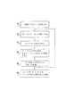
図1は、本発明の好ましい実施の形態に基づく埋め込み可能な受動タグ20の一部切り欠き模式図である。ここで図示され説明されるタイプのタグ20は、「ビーコン」とも呼ばれる。タグ20はRFアンテナ22を有し、RFアンテナ22は典型的にはコイルの形態を有し、キャパシタ24および別の回路26に接続されていて共振回路を形成している。コイル、キャパシタ、および回路は、密閉された生体適合性を有するパッケージ28内に収容されていて、パッケージ28は典型的にはプラスチックまたはその他の非導電性材料で作られている。図1に示された実施の形態では、パッケージ28は基部を含んでいて、この基部はタグ20を患者の軟組織の所望の位置に配置するために放射線専門医によって適切なインサーター器具(図示せず)を用いて把持される。 FIG. 1 is a partially cutaway schematic view of an implantable
好ましくは、回路26はln3712ダイオードのようなトンネルダイオード(図示せず)を有し、そのトンネルダイオードはアンテナ22およびキャパシタ24と共に当業者に知られたトンネルダイオード発振回路を形成している。例えば、アンテナは0.5mmワイヤの小さいループによって形成されていて40pFのキャパシタに接続されている。トンネルダイオード発振回路の設計と無線トランスポンダーでのトンネルダイオード発振回路の使用についての詳細は、上述された米国特許第6,053,873号に記載されている。簡略に述べると、発振回路は外部で生成された電磁界によって第1の周波数(f1)で励振されて、発振回路が応答フィールド(電磁界)を第2の周波数(f2)で放射する。トンネルダイオードはこの目的にとりわけ適していて、その理由はトンネルダイオードのI−V特性曲線がダイオードが負性抵抗を示す部分すなわちダイオードに印加される電圧が減少するとダイオードを流れる電流が増加する部分を含み、発振回路が発振を起こすからである。発振周波数(f2)は、トンネルダイオードの実効キャパシタンスによって発振回路の通常の共振周波数とは異なる値となる。典型的には、周波数f2は励振周波数f1とは約10%から40%までの範囲内で異なる。例えば、88MHzの励振周波数f1によって、120MHzの周波数f2の応答電磁界が得られる。応答電磁界の強度および向きは、以下に説明されるように、タグ20の位置に「帰巣する(home in)」ために用いられる。代わりに、その他のタイプの再放射発振器がこの目的のために用いられてもよい。 Preferably,
図2は、本発明の好ましい実施の形態に基づく患者の乳房内へのタグ20の埋め込みと、タグ20を手術器具32の誘導に用いる様子を示した模式図である。典型的には、手術器具32はプローブ34からなり、例えばタグ20によってマークされた位置で乳房30から生検試料を切断して抽出するために用いられる。手術器具32は、励振および検出回路に接続され手術器具32内または別の処理ユニット(図示せず)内に収容されたアンテナアセンブリ36を有する。アンテナアセンブリ36は、タグ20内の回路の励振周波数f1でまたは励振周波数f1に近い値の周波数でRFエネルギーを放射するように駆動される。この励振エネルギーによって、タグ20が周波数f2で応答電磁界を放射することになり、放射された応答電磁界はアンテナアセンブリ36によって検出される。典型的には、アンテナアセンブリ36は、プローブ34の長手方向の軸の周りに間隔を置いて配置された2個以上のアンテナ(図示せず)を有する。周波数f2で(複数の)アンテナによって検出される応答電磁界の強さの差は、タグ20の位置に対するプローブの軸の不整合の向きおよび程度を示している。検出された応答電磁界に基づいて、手術器具32のハンドルに設けられたディスプレイ38は、外科医がプローブ34をタグ20の位置に正確に方向付けるように手引きする。(複数の)アンテナからの信号が等しくなったとき、プローブの軸がタグ20に整合している。 FIG. 2 is a schematic diagram showing how the
図3は、本発明の好ましい実施の形態に基づくタグ20および手術器具32を用いて手術手技を行なうための方法を模式的に示したフロー図である。タグ20は、最初にステップ(埋め込みステップ)40で放射線専門医によって乳房30内に埋め込まれる。このステップは、典型的にはタグ20を病巣内または病巣の近くに配置するために、疑わしい病巣の位置を決定するために乳房の像を写しながら実行される。次に、外科医がプローブ34を乳房の近くに移す。ステップ(電力伝送ステップ)42では、アンテナアセンブリ36がプローブ34の向きに沿ってRF電磁界を乳房へ向けて伝送する。上述されたように、伝送される電磁界は、タグ20内の発振回路の励振周波数または励振周波数に近い周波数である。ステップ(ビーコン伝送ステップ)44では、発振回路で発生した発振によって、発振回路は応答電磁界またはビーコン信号を放射する。 FIG. 3 is a flow diagram schematically illustrating a method for performing a surgical procedure using the
アンテナアセンブリ36は、ステップ(ビーコン受信ステップ)46でビーコン信号を受信し、受信されたビーコン信号が処理されて、その強度特性と、必要に応じてその方向特性とが測定される。これらの特性は、ディスプレイを駆動するのに用いられて、外科医にプローブ34がタグ20に到達するためにはプローブ34を乳房組織中でどのように方向付けるべきかを視覚的に指示する。ある実施の形態では、ディスプレイ38は単に信号の強度のみを表示し、外科医は信号の強度が最小となるようにプローブ34を方向付ける。他の実施の形態では、典型的には、上述されたようにアンテナアセンブリ36内の複数のアンテナを用いて、方向信号を生成するように応答信号が処理される。アンテナの出力がアナログおよび/またはデジタル差動処理回路を用いて処理されて、ディスプレイ38上のポインタまたはカーソルを駆動し、プローブ34からタグ20までの向きが表示される。必要に応じて、医療器具32は、プローブ34が乳房30内の目標に正しく方向付けられているか否かを外科医に知らせるために、音または一連の音のような可聴表示をも提供してよい。 The
ステップ(ガイダンスステップ)48では、外科医はディスプレイ38によって提供された情報を用いてプローブ34をタグ20に向けて誘導する。ステップ(成功ステップ)50で、プローブ34の先端がタグ20の位置に到達するまで、ステップ42からステップ48までが連続して繰り返される。プローブ34の先端がタグ20の位置まで成功裏に穿通したことは、さまざまな異なる方法で判定される。例えば、アンテナまたはその他のセンサーがプローブの先端の近くに組み込まれていて、プローブがタグに接触したときに信号を発生することによって判定される。代わりに、アンテナアセンブリ36内の複数のアンテナの各々が、アンテナからタグの位置を指し示す対応する方向ベクトルを見出すために用いられてよい。これらのベクトルが交差する点がタグの位置を示している。したがって、アンテナアセンブリ36からベクトルの交差する点までの距離がプローブ34の既知の長さに等しくなったとき、プローブの先端がタグの位置に到達したと判定される。この時点で、ディスプレイ38は好ましくは成功の表示を色の変化または可聴信号によって行う。次に、外科医はバイオプシーまたは保証されているその他の手技を完了することができる。タグ20は、この手技の一部として外科的に除去されても、将来のアクセスのためにその位置に残されてもよい。 In step (guidance step) 48, the surgeon guides probe 34 toward
図4は、本発明の他の好ましい実施の形態に基づく埋め込み可能な受動タグ54の一部切り欠き模式図である。タグ54は、アンテナ22に加えて、ひとつまたは複数の位置検出コイル56を有する。外部のフィールド発生器によってコイル56に電磁界を印加することにより、コイル56に電流が流れる。電流の大きさは、これらのコイル56のフィールド発生器に対する位置座標および姿勢(向き)座標を求めるのに用いられる(以下で図6に示される)。そのようなコイルを用いた侵襲的な装置の位置および姿勢を決定する方法の例は、ベン−ハイム(Ben-Haim)による米国特許第5,391,199号、および1997年5月14日に出願された米国特許出願第08/793,371号(ベン−ハイムら(Ben-Haim et al.)による国際公開第96/05768号パンフレット)に記載されていて、これらの特許および特許出願は参照文献として引用される。3個の位置検出コイル56はタグ54の6次元の位置および姿勢座標を提供する。6次元情報の全てを必要とはしない用途では、ひとつの位置検出センサー56で十分である。 FIG. 4 is a partially cutaway schematic view of an implantable
コイル56は制御回路58に接続されていて、制御回路58はコイル56を流れる電流を感知して感知した電流をタグ54の座標を求めるのに用いる。好ましくは、制御回路58は、コイル56を流れる電流の大きさが符号化された信号を生成して、その信号をアンテナ22によって伝送する。その信号は外部の処理ユニットによって復号され処理されて、タグ54の座標が求められる。必要に応じて、タグ54はひとつまたは複数の別のセンサー60をさらに有し、そのセンサー60は体内のタグ54が配置された部位の生理学上の変数(パラメータ)を測定する。そのようなセンサーの例として、温度センサー、圧力センサー、pHセンサー、および、タグ54が接触している組織の物理的および化学的特性を測定するその他のセンサーがある。制御回路58は、それらのセンサーの測定値をも符号化し伝送する。 The
図5は、本発明の好ましい実施の形態に基づくタグ54の回路要素を示す電気的な模式図である。アンテナ22は、好ましくは1MHz以上の範囲の高周波信号を受信し伝送するように最適化されている。一方、コイル56は好ましくは外部のフィールド発生器が生成する電磁界の周波数である1kHzから3kHzまでの範囲内の周波数で動作するように設計されている。代わりに、その他の範囲の周波数が用途の必要性に応じて用いられてよい。この実施の形態に基づけば、タグ54は、典型的には実質的に2mmから5mmまでの範囲内の長さを有し、実質的に2mmから3mmまでの範囲内の外径を有する。このタイプのタグの別の側面は、上述された米国特許第10/029,473号に記載されている。 FIG. 5 is an electrical schematic diagram showing circuit elements of
タグ54の位置を求めるために、さまざまな既知の位置および/または姿勢の複数のフィールド発生器によってタグ54を収容する患者の体の領域に電界が印加される。好ましくは、フィールド発生器の各々の動作周波数は互いに異なる。制御回路58は、コイル56を流れるフィールド周波数が異なる電流を測定し、それらの測定値をアンテナ22を介して伝送される高周波数信号に符号化する。代わりにまたはさらに、複数の異なるフィールド発生器が時間多重されて、各フィールド発生器が割り当てられたタイムスロットの間動作する。 To determine the position of the
図5に示された実施の形態では、制御回路58は電圧−周波数(V/F)変換器62を有し、その電圧−周波数変換器62は、センサーコイルを流れる電流によって負荷の両端に生じた電圧に比例する周波数を有するRF信号を生成する。好ましくは、制御回路58によって生成されたRF信号は、50MHzから150MHzまでの範囲内のキャリア周波数を有する。このようにして生成されたRF信号は、フィールド発生器によって生成された電磁界の各周波数で時間的に変化する複数の異なる周波数変調(FM)成分によって変調される。変調の振幅は、異なる周波数の電流成分に比例する。患者の体の外側のレシーバーは、RF信号を復調して電流成分の振幅を求めてタグ54の座標を計算する。 In the embodiment shown in FIG. 5, the
代わりに、制御回路58は、センサーコイル56を流れる電流の振幅をデジタル化するサンプリング回路およびアナログ/デジタル(A/D)変換器(図示せず)を有してもよい。その場合、制御回路58は、デジタル的に変調された信号を生成し、その信号をアンテナ22によって伝送するためにRF変調する。この目的のために任意の適切なデジタル符号化および変調方法が用いられてよい。その他の信号処理および変調方法も当業者には明らかであろう。 Alternatively, the
図6は、本発明の好ましい実施の形態に基づく乳房30内のタグ54の位置に手術器具76を誘導するためのシステム66の模式図である。電源コイル68は好ましくは2MHzから10MHzまでの範囲内の高周波RF電磁界を生成する。この電磁界はアンテナ22内に電流を流し、その電流が制御回路58によって整流されて制御回路58の内部回路に電力を供給するのに用いられる。一方、フィールド発生器コイル70は好ましくは1kHzから3kHzまでの範囲内の周波数の電磁界を生成し、その電磁界が(ひとつまたは複数の)センサーコイル56内に電流を流す。これらの電流は、フィールド発生器コイルを流れる駆動電流と同じ周波数の周波数成分を有する。電流成分は、センサーコイル56の軸と平行な方向でフィールド発生器コイル70によって生成された対応する磁界の成分の強度に比例する。したがって、電流の振幅は、固定されたフィールド発生器コイル70に対するセンサーコイル56の位置および姿勢を表している。 FIG. 6 is a schematic diagram of a
制御回路58は、コイル56からの電流の振幅をアンテナ22を介して伝送される高周波信号に符号化する。代わりに、タグ54は、例えば上述された米国特許第6,239,724号に記載されているようにRF電力を受信するためのアンテナと、信号を伝送するためのアンテナを別々に有してもよい。符号化された信号はコイル68または他の受信用アンテナによって受信されて、処理ユニット72に伝達される。典型的には、処理ユニット72は、適切な入力回路とタグ54から空気を介して受信された位置信号を処理するためのソフトウエアとを備えた汎用コンピュータからなる。処理ユニットは、タグ54の位置座標、および必要に応じて姿勢座標を計算し、タグの座標をディスプレイ74に表示する。 The
手術器具76は、位置センサー78をも有し、位置センサー78はタグ54内のコイル56と同じ形態および機能のひとつまたは複数のコイルを有する。フィールド発生器コイル70によって生成される電磁界は、コイル70に対する手術器具76の位置および姿勢に応じてセンサー78内にも電流を流す。生成された電流信号も、タグ54の場合のように空気を介して、または有線で処理ユニット72に伝送される。センサー78が空気を介して信号を伝送する場合、タグ54とは異なるキャリア周波数を使用して信号同士が容易に区別されるようにするのが好ましい。
タグ54およびセンサー78からの信号に基づいて、処理ユニット72は、乳房30内のタグ54の位置に対する手術器具76の位置および姿勢を計算する。ポインタおよび/またはカーソルがティスプレイ74上に表示されて手術器具がその目標(タグ)に正しく向けられているか否かを外科医に示す。座標を表示するためのさまざまな方法がこの目的のために用いられてよく、例えば、3次元格子メッシュ、2次元格子メッシュ、2次元または3次元極座標表示、数値による座標表示、または当業者に知られた他の方法が用いられてよい。必要に応じて、タグおよび手術器具の位置がその測定された位置および姿勢を用いて、X線、CT、または超音波イメージなどの乳房30のイメージと共に登録される。乳房30のイメージがディスプレイ74上に表示され、タグおよび手術器具の位置に対応するアイコンがイメージ上に重ね合わされる。イメージで誘導される手術に用いるのに有用な別の表示方法が上述された米国特許第6,332,098号に記載されている。 Based on the signals from
図7は、本発明の他の好ましい実施の形態に基づく乳房30内のタグ81の位置に手術器具を誘導するためのシステム80の模式図である。この実施の形態では、タグ81は、その動作電力を(コイル68のように)電磁界からではなく、超音波トランスミッター82によって生成された音響エネルギーから得る。この種のタグは、例えば、上述された米国特許出願第10/029,595号に示されている。トランスミッター82によって生成された音響エネルギーは、タグ81内の圧電性結晶などの小型のトランスデューサを励振して、電気的エネルギーを生成する。生成された電気的エネルギーは上述されたコイル56のようなタグ81内のひとつまたは複数のコイル内に電流を流す。タグ81内のコイルを流れる電流は、乳房30の外側に電磁界を生成し、その電磁界はこの実施の形態ではコイル70(この場合フィールド発生器としてではなくフィールド受信機として働く)によって受信される。供給された音響エネルギーの周波数と同じ周波数でコイル70を流れる電流の振幅が測定されて、タグ81の位置が求められる。 FIG. 7 is a schematic diagram of a
代わりに、タグ81は、タグ内の(ひとつまたは複数の)センサーコイル56がコイル70によって生成されたフィールドを受信し,タグ内の回路がコイル56の電流成分の振幅を表す信号を伝送するという点で、タグ54と同じように動作してよい。しかし、図7の実施の形態では、タグ内の回路はコイル68からの電力ではなくトランスミッター82によって印加された音響エネルギーに応答してタグ81内の圧電性結晶(または他のトランスデューサ)が生成した電気的エネルギーを整流することによって電力を得る。タグ81は、信号を連続的ではなくパルス的に伝送してよく、キャパシタはパルスとパルスの間の期間内にタグ81にエネルギーを蓄えるために用いられて伝送される信号が良好な信号/雑音比で体の外側で受信されるのに十分な電力を有するようにされてよい。 Instead, the
前述された実施の形態のように、センサー78は手術器具76の位置および姿勢を求めるために用いられる。センサー78は、上述されたようにコイル70によって生成されたフィールドを受信しても、コイル70によって受信されるフィールドを生成するように駆動されてもよい。 As in the previous embodiment,
タグ81およびセンサー78によって生成された位置信号は、組み合わされた位置パッドおよびディスプレイユニット84によって受信されて処理される。このユニット84は、前述された実施の形態で用いられている別個の処理ユニット72、コイル70、およびディスプレイ74に代わるものである。ユニット84は、好ましくは、安定した移動可能な取り付け部(図示せず)によって保持されていて、外科医が乳房30の近くでかつユニットのディスプレイ86を見るのに好都合な位置にユニット84を配置できるようにする。フィールド発生器コイル70は、ユニット84内に組込まれていて、タグ81および手術器具76のユニットに対する位置が求められる。コイル70は切り欠きされて図示されているが、通常は非導電性のカバーで保護されたユニットのケース内に収容されている。重要なのはタグ81および手術器具76の絶対的な位置ではなく相対的な位置および姿勢なので、外科医は手術中に必要に応じてユニット84を動かして、タグ81およびセンサー78からの信号が十分に強く、ディスプレイ86を容易に見ることができ、ユニット84自体が外科医の作業を妨げないようにすることができる。 The position signal generated by
ディスプレイ86は好ましくは距離誘導器88および姿勢目標92を有する。距離誘導器88のマーク90は医療器具76の先端がタグ81の位置からどれだけ離れているかを示す。目標92のカーソル94はタグ81の位置に到達するのに必要な軸に対する手術器具76の姿勢を示す。カーソル94が目標に位置合わせされたとき、手術器具76がタグ81に向けて方向付けられたことを意味する。ディスプレイ38(図2)は、好ましくは同様の原則で動作する。
図8は、本発明の好ましい実施の形態に基づくタグ81および組み合わされた位置パッドおよびディスプレイユニット84を含むシステム80を用いて手術手技を行なうための方法を模式的に示すフロー図である。図6に示されたシステム66の要素を用いて必要な変更を加えて同様な手技が実行される。図3を参照して説明されたように、手技は、ステップ(埋め込みステップ)100で乳房30内の目標の位置に適切なタグを埋め込むことによって開始される。タグは次に、ステップ(励振ステップ)102で乳房にトランスミッター82を配置してトランスミッターを駆動して音響エネルギーを生成することによって励振される。代わりに、タグ54が用いられる場合には、コイル68が用いられてタグがRF電力によって励振されてよい。 FIG. 8 is a flow diagram that schematically illustrates a method for performing a surgical procedure using a
ステップ(伝送ステップ)104では、励振されたタグは位置信号をユニット84に伝送する。同時にまたはタグが位置信号を伝送する代わりに、ステップ(手術器具伝送ステップ)106では、センサー78も位置信号をユニット84に伝送する。ステップ(座標決定ステップ)108では、ユニット84(または図6の実施の形態の処理ユニット72)は、位置信号を受信し手術器具76およびタグ81の相対座標を求める。求められた相対座標に基づいて医療器具76のタグ81に対する位置および姿勢が上述されたようにディスプレイ86に表示される。 In step (transmission step) 104, the excited tag transmits a position signal to
ステップ(プローブ誘導ステップ)110では、外科医はディスプレイ86に表示された情報を用いて手術器具の先端をタグ81の位置に誘導する。典型的な操作では、外科医は手術器具を選択された開始位置に保持し、目標92を用いて手術器具をタグ81に向けて方向付ける。次に外科医はカーソル94を目標92に中心合わせした状態に保ちながら手術器具を乳房30内に前進させる。ステップ102からステップ110は、ステップ(成功ステップ)112でマーク90が手術器具がタグ81の位置に到達したことを示すまで連続して繰り返される。バイオプシーまたはその他の望まれる手技が次に実行される。 In step (probe guiding step) 110, the surgeon guides the distal end of the surgical instrument to the position of the
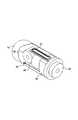
図9は、本発明の他の好ましい実施の形態に基づく超音波反射タグ120を示す一部切り欠き模式図である。本発明の目的に用いることのできるこの種のさまざまなタグが、上述された米国特許出願第10/029,595号に示され説明されている。この実施の形態のタグ120は、球状のバブル(半球形のもの)の形態を有し、患者の体の外側の音響トランスデューサが生成した超音波に打たれるシェル122を有する。入射した超音波はタグに共鳴を起こし、タグは検出可能な超音波エコーを放射する。シェル122が(図示されているように)球状の場合、放射されたエコーは実質的に等方性であり、エコーを三角測量することによって体内の目標の位置を知ることができる。 FIG. 9 is a partially cutaway schematic view showing an
好ましくは、シェル122は媒体124を収容していて、シェル122および媒体124が入射した超音波に対して非線形に振動して応答するように構成されている。患者の体の外側の音響発生器が放射した周波数f1の超音波は、シェル122を打ち、シェルおよび/または収容された媒体にエネルギーを与える。次にシェル122は周波数f1とは異なるその共振周波数f2で超音波を放射する。共振周波数は、当業者に知られているように、シェルの半径、ヤング率、および厚みなどの変数によって決まる。好ましくは、強いエコーを生成するために、タグ120の設計変数および励振周波数f1は、f2がf1の倍数となるように選択される。 Preferably, the
図10は、本発明の好ましい実視の形態に基づく乳房30内のタグ120の位置へ手術器具を誘導するためのシステム125の模式図である。この実施の形態も上述された組み合わされた位置パッドおよびディスプレイユニット84を用いる。複数の超音波トランスデューサ126が乳房30に取り付けられる。各トランスデューサ126は、順番に、周波数f1のパルス状の超音波エネルギーを生成するように駆動されて、タグ120によって返された周波数f2のエコー信号を検出する。代わりにまたはさらに、全てのトランスデューサ126が、ひとつのトランスデューサが生成した超音波パルスによる返されたエコーを検出してもよい。超音波パルスの発生からエコーの受信までの遅延時間が各トランスデューサ126からタグ120までの距離を示している。代わりにまたはさらに、各トランスデューサ126によって受信されたエコー信号の電力が距離を求めるために用いられてもよい。 FIG. 10 is a schematic diagram of a
しかし、乳房30内のタグ120の実際の位置を求めるためには、トランスデューサ126の位置を知る必要がある。この目的のために、センサーコイル128が各トランスデューサ126に取り付けられている。ユニット84内のフィールド発生器コイル70を励振することによりセンサーコイル128内に電流を流す。これらの電流の振幅は、上述されたように、フィールド発生器コイルに対するセンサーコイルの位置および姿勢に応じて変わる。ユニット84は、センサーコイル128を流れる電流を分析してトランスデューサ126の位置座標を求める。求められた位置座標および各トランスデューサ126からタグ120までの超音波の反射によって測定された距離に基づいて、ユニット84は、固定された外部のフレームを基準としたタグの正確な位置を求めることができる。 However, in order to determine the actual position of the
ユニット84に対する手術器具76の位置座標および姿勢座標は上述されたようにセンサー78を用いて求められ、手術器具からタグ120までの距離および向きも計算されて表示される。 The position coordinates and posture coordinates of the
システム125はタグ120の位置を見出すための2組の位置の測定値、すなわち、ユニット84に対するトランスデューサ126の位置、および、トランスデューサ126に対するタグ120の位置を用いていることが分かる。このような追加された複雑さは前述された実施の形態には存在しない。一方、タグ20、タグ54、およびタグ81と比較して、タグ120は非常に簡単で、製造コストが低く、必要に応じて非常に小型に製造できる。典型的には、タグ120は2mm未満の直径を有する。 It can be seen that the
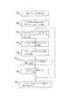
図11は、本発明の好ましい実施の形態に基づくタグ120を含むシステム125を用いて手術手技を行なうための方法を模式的に示したフロー図である。この実施の形態でも、ステップ(埋め込みステップ)130で放射線専門医によって乳房内の疑わしい病巣の部位にタグ120が埋め込まれることによって手技が開始される。好ましくは、この目的のために、シェル122の材料は標準的な画像化技術を用いて明瞭に見ることのできるものが選択される。次に、ステップ(トランスデューサ固定ステップ)132で、手術の準備として、トランスデューサ126がタグ120の位置の周囲の乳房30の皮膚に固定される。 FIG. 11 is a flow diagram schematically illustrating a method for performing a surgical procedure using a
ステップ(RF配置ステップ)134では、手術器具76およびトランスデューサ126の相対的な位置および姿勢を見出すために、フィールド発生器コイル70が駆動されて、センサー78およびセンサーコイル128を流れる電流が測定される。代わりに、この目的のために他の位置検出技術が用いられてもよい。例えば、ステップ134では、手術器具76およびトランスデューサ126の両方が患者の体の外側にあるので、光学的な検出技術が手術器具126およびトランスデューサ126の座標を見出すために用いられてもよい。超音波位置検出技術も同様に用いられてよい。 In step (RF placement step) 134,
ステップ(エコー測定ステップ)136では、トランスデューサ126が駆動されて、タグ120からのエコーがトランスデューサ126によって受信されて測定される。エコーは上述されたように各トランスデューサ126からタグ120までの距離を求めるのに用いられる。ステップ134とステップ136の順番は逆にしてもよい。次に、ステップ(三角測量ステップ)138で、ユニット84は必要な幾何学的計算および変換を実行してタグ120に対する手術器具76の位置座標および姿勢座標を求める。ステップ(表示ステップ)140では、上述されたように、タグからの手術器具の距離およびタグへ直接向かう軸に対する手術器具の姿勢がディスプレイ86に表示される。 In step (echo measurement step) 136, the
ステップ(プローブ誘導ステップ)142では、外科医はディスプレイ86に表示された情報を用いてタグ120の位置へ向けて手術器具76の先端を誘導する。上述されたように、外科医はカーソル94を目標92の中心に保ちながら乳房30内の手術器具を前進させる。ステップ(成功ステップ)144でマーク90によって手術器具がタグ81の位置に到達したことが示されるまでステップ134からステップ142までが連続して繰り返される。次に、バイオプシーまたはその他の望まれる手技が行われてよい。 In step (probe guiding step) 142, the surgeon guides the distal end of the
上述された全ての実施の形態は乳房の手術に関して説明され、特に乳房のバイオプシーに関して説明されたが、これらの実施の形態で用いられた装置および方法は、他の体組織に対する他の手技および治療にも適合させることができる。例えば、上述されたタグは強度焦点放射線によって治療される体組織内に埋め込まれてよい。そのような技術は、典型的には、体内の組織またはその他の病巣のアブレーションに用いられる。この種の治療の用途では、放射線専門医は治療されるべき位置にタグを埋め込み、次に、治療のために用いられる放射線源がタグの位置に誘導される。即ち、図10を再び参照すると、トランスデューサ126が強度焦点超音波(HIFU)治療に用いられるのに適したものである場合、ユニット84によって生成された位置信号および表示を用いてトランスデューサ126はタグ120の位置に向けられ誘導される。 Although all the embodiments described above have been described with respect to breast surgery, and in particular with regard to breast biopsy, the devices and methods used in these embodiments can be used for other procedures and treatments for other body tissues. Can also be adapted. For example, the tags described above may be implanted in body tissue that is treated with intense focus radiation. Such techniques are typically used for ablation of body tissues or other lesions. In this type of therapeutic application, the radiologist implants the tag at the location to be treated, and then the radiation source used for treatment is directed to the location of the tag. That is, referring again to FIG. 10, if the
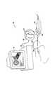
図12は、本発明の好ましい実施の形態に基づく気管支鏡検査法でのタグ20の使用を示す模式図である。タグ20は、患者152の肺150内で実行された画像化手技の間に発見された疑わしい結節154に固定される。気管支鏡156が用いられて視診が行なわれ、可能ならば結節154が生体組織採取検査(バイオプシー)される。後の気管支鏡検査で追跡調査するために同じ結節の位置に容易に戻ることができることも好ましい。医師157は、ハンドル158を把持して操縦することにより気管支鏡156を操作する。気管支鏡156は図2に示された手術器具と同じ要素を有し、気管支鏡の先端にはアンテナアセンブリ36(適切に適合され小型化されている)があり、ハンドル158にはディスプレイ38がある。ディスプレイ38を見ながら、医師157はステアリングノブ160を回して肺150の中に気管支鏡157を進めて結節154の位置に気管支鏡を到達させる。 FIG. 12 is a schematic diagram illustrating the use of
この実施の形態は、図1に示されたタグ20に基づくものであるが、その他のRFに基づく上述されたタグ(図4に示されたタグ54など)をこの目的に用いてもよい。一方、超音波の利用に基づくタグは、典型的には肺に用いるためには満足のいくものではない。 This embodiment is based on the
図13は、本発明の好ましい実施の形態に基づく結腸鏡検査手技へのタグ120の使用を示す模式図である。この例では、タグ120は患者の結腸162で発見されたポリープ164に固定される。超音波トランスデューサ126(図13には示されていないが図10に示されている)が患者の腹部に固定され、上述された方法でタグ120の位置を求めることができるようにされている。結腸鏡160は、結腸162内を進められ、その位置がセンサー78によって追跡される。結腸鏡160の先端がタグ120の位置に到達すると、ユニット84は結腸鏡160からタグ120までの距離および向きを表示する。必要に応じて、タグ120の位置を示すアイコンが、結腸鏡内の画像センサーによって形成され適切なビデオディスプレイ上に表示された結腸162の内部のビデオ画像に重ね合わされる。 FIG. 13 is a schematic diagram illustrating the use of
上述された好ましい実施の形態は、特定の体器官での特定の医療および手術手技に関して説明されたが、本発明のタグ、補助器具、および方法をその他の領域に用いることも当業者には明らかである。本発明の原則は、最小侵襲的外科手術、内視鏡および非侵襲的治療および診断療法を含むその他のタイプの外科手術にも同様に用いることができる。 Although the preferred embodiments described above have been described with respect to specific medical and surgical procedures on specific body organs, it will be apparent to those skilled in the art that the tags, aids, and methods of the present invention may be used in other areas. It is. The principles of the present invention can be used in other types of surgery as well, including minimally invasive surgery, endoscopes and non-invasive treatments and diagnostic therapies.
上述された好ましい実施の形態は例示として記載されたものであること、および本発明が上記の特定的に示され記載されたものに限定されないことが適切に理解される。むしろ、本発明の範囲は、上述されたさまざまな特徴、および上記の記載から当業者が思い浮かべることができかつ従来技術に開示されていない変形および変更の組み合わせおよび部分的な組み合わせの両方を含む。 It will be appreciated that the preferred embodiments described above have been described by way of example and that the invention is not limited to what has been particularly shown and described hereinabove. Rather, the scope of the present invention includes both the various features described above and combinations and partial combinations of variations and modifications that can be imagined by those skilled in the art from the above description and are not disclosed in the prior art. .
この発明の具体的な実施態様、参考態様は以下の通りである。
(実施態様A)
対象の体内の組織に医療手技を行なうための装置であって、
上記組織に固定され、かつ放射線を放射するように適合されていることにより上記体内での位置を示す第1の信号を生成する無線タグと、
侵襲的医療器具であって、上記体内に穿通して上記組織に到達するように適合されたプローブ、上記プローブより近位の側に配置されかつ上記医療器具の操作者によって操縦されるように適合されたハンドル、および、上記ハンドルに取り付けられかつ上記タグに対する上記プローブの姿勢の視覚的な表示を上記操作者に提供するように適合されたディスプレイを備えた、上記侵襲的医療器具と、
上記第1の信号に結合されて上記プローブに対する上記タグの座標を求めかつ上記座標に応答して上記ディスプレイを駆動する処理ユニットと
を有する、医療手技を行なうための装置。
(1)侵襲的医療器具がレシーバーをさらに有し、上記レシーバーが、無線タグによって放射された放射線を受信するように適合されていて、かつ処理ユニットによって処理される第1の信号を上記放射線に応答して生成する、実施態様A記載の装置。
(2)タグによって放射される放射線が、無線周波数(RF)の電磁界の放射線である、実施態様(1)記載の装置。
(3)侵襲的医療器具が器具位置センサーをさらに有し、上記器具位置センサーは、プローブの座標を示す第2の信号を生成するように適合されていて、処理ユニットが第1の信号および上記第2の信号を処理するように結合されていて上記プローブに対するタグの座標を求める、実施態様A記載の装置。
(4)ひとつまたは複数のフィールド発生器をさらに有し、上記フィールド発生器は、基準となる外部フレームに固定され組織の近傍で電磁界を生成するように適合されていて、無線タグおよび器具位置センサーが、上記電磁界に応答して電流が流れるフィールドセンサーを有し、第1の信号および第2の信号が、上記フィールドセンサーを流れる電流を示す、実施態様(3)記載の装置。
(5)タグによって放射される放射線が、無線周波数(RF)の電磁界の放射線である、実施態様A記載の装置。
Specific embodimentsand reference embodiments of the present invention are as follows.
(Embodiment A)
A device for performing a medical procedure on tissue in a subject's body,
A wireless tag that is fixed to the tissue and adapted to emit radiation to generate a first signal indicative of a position within the body;
An invasive medical device, a probe adapted to penetrate the body and reach the tissue, adapted to be positioned proximal to the probe and to be steered by an operator of the medical device The invasive medical device comprising: a handle adapted to the operator; and a display attached to the handle and adapted to provide the operator with a visual indication of the posture of the probe relative to the tag;
A processing unit coupled to the first signal for determining the coordinates of the tag relative to the probe and driving the display in response to the coordinates;
A device for performing a medical procedure.
(1) The invasive medical device further comprises a receiver, the receiver is adapted to receive radiation emitted by the wireless tag and the first signal processed by the processing unit is transmitted to the radiation. The device ofembodiment A , generated in response.
(2) The apparatus of embodiment (1), wherein the radiation emitted by the tag is radio frequency (RF) electromagnetic radiation.
(3) the invasive medical instrument further comprises an instrument position sensor, the instrument position sensor adapted to generate a second signal indicative of the coordinates of the probe, wherein the processing unit The apparatus ofembodiment A , coupled to process a second signal and determining the coordinates of the tag relative to the probe.
(4) It further has one or a plurality of field generators, and the field generators are fixed to the reference outer frame and are adapted to generate an electromagnetic field in the vicinity of the tissue. The apparatus of embodiment (3), wherein the sensor comprises a field sensor through which a current flows in response to the electromagnetic field, and wherein the first signal and the second signal indicate the current through the field sensor.
(5) The apparatus ofembodiment A ,wherein the radiation emitted by the tag is radio frequency (RF) electromagnetic field radiation.
(6)ひとつまたは複数の音響トランスミッターをさらに有し、上記音響トランスミッターが、組織の近傍の体内に音響エネルギーを伝達するように適合されていて、タグが上記音響エネルギーを受信して上記音響エネルギーを用いて電磁界の放射線を生成する、実施態様(5)記載の装置。
(7)タグによって放射される放射線が音響の放射線である、実施態様A記載の装置。
(8)ディスプレイが、プローブからタグまでの距離の視覚的な表示をさらに提供するように適合されている、実施態様A記載の装置。
(9)侵襲的医療器具が組織に外科手術を行なうように適合されている、実施態様A記載の装置。
(10)侵襲的医療器具が内視鏡を有する、実施態様A記載の装置。
(6) further comprising one or more acoustic transmitters, wherein the acoustic transmitter is adapted to transmit acoustic energy into a body in the vicinity of the tissue, and the tag receives the acoustic energy and transmits the acoustic energy. The apparatus of embodiment (5), wherein the apparatus is used to generate electromagnetic radiation.
(7) The apparatus ofembodiment A ,wherein the radiation emitted by the tag is acoustic radiation.
The apparatus ofembodiment A ,wherein the display is adapted to further provide a visual indication of the distance from the probe to the tag.
The apparatus ofembodiment A ,wherein the invasive medical instrument is adapted to perform a surgical operation on the tissue.
(10) The apparatus according toembodiment A ,wherein the invasive medical instrument has an endoscope.
(参考態様B)
対象の体内の組織に医療手技を行なうための方法であって、
上記組織に無線タグを固定する過程と、
上記タグを駆動して放射線を放射させて、上記体内での上記タグの位置を示す第1の信号を生成する過程と、
侵襲的医療器具のハンドルを操縦して上記体内に上記医療器具を導入する過程と、
上記第1の信号を処理して上記医療器具に対する上記タグの座標を求める過程と、
上記座標に応答して上記タグに対する上記医療器具の姿勢の視覚的な表示を上記医療器具の上記ハンドルに表示する過程と、
上記医療器具が上記タグに到達するように上記視覚的な表示を観察しながら上記ハンドルを操縦して上記組織に向けて上記体内で上記医療器具を進める過程と
を有する、医療手技を行なうための方法。
(11)タグの座標を求める過程が、医療器具内のレシーバーを用いて無線タグによって放射された放射線を受信する過程と、上記受信された放射線に応答して第1の信号を生成する過程とを有する、参考態様B記載の方法。
(12)無線タグによって放射された放射線を受信する過程が、無線周波数(RF)の電磁界の放射線を受信する過程を有する、参考態様(11)記載の方法。
(13)侵襲的医療器具に結合された器具位置センサーが生成する上記侵襲的医療器具の座標を示す第2の信号を受信する過程をさらに有し、タグの座標を求める過程が、第1の信号および上記第2の信号を処理してプローブに対する上記タグの座標を求める過程を有する、参考態様B記載の方法。
(14)第1の信号を生成する過程が、組織の近傍で電磁界を生成する過程を有し、無線タグおよび器具位置センサーが、上記電磁界に応答して電流が流れるフィールドセンサーを有し、上記第1の信号および第2の信号が、上記フィールドセンサーを流れる電流を示す、参考態様(13)記載の方法。
(15)第1の信号を生成する過程が、タグを駆動して無線周波数(RF)の電磁界の放射線を放射する過程を有する、参考態様B記載の方法。
(Reference embodiment B)
A method for performing a medical procedure on tissue in a subject's body,
Fixing the wireless tag to the above organization;
Driving the tag to emit radiation to generate a first signal indicative of the position of the tag in the body;
Steering the handle of an invasive medical device and introducing the medical device into the body;
Processing the first signal to determine the coordinates of the tag relative to the medical device;
Displaying a visual indication of the posture of the medical device relative to the tag in response to the coordinates on the handle of the medical device;
Steering the handle while observing the visual indication so that the medical device reaches the tag and advancing the medical device in the body toward the tissue;
A method for performing a medical procedure.
(11) The process of obtaining the coordinates of the tag includes a process of receiving radiation emitted by the wireless tag using a receiver in the medical instrument, and a process of generating a first signal in response to the received radiation. A method according toReference Aspect B , having
(12) The method according to thereference aspect (11), wherein the step of receiving the radiation emitted by the wireless tag includes the step of receiving radiation of an electromagnetic field of a radio frequency (RF).
(13) The method further includes receiving a second signal indicating the coordinates of the invasive medical instrument generated by the instrument position sensor coupled to the invasive medical instrument. A method according toReference Aspect B , comprising processing the signal and the second signal to determine the coordinates of the tag relative to the probe.
(14) The process of generating the first signal includes a process of generating an electromagnetic field in the vicinity of the tissue, and the wireless tag and the instrument position sensor include a field sensor through which a current flows in response to the electromagnetic field. The method according toreference aspect (13), wherein the first signal and the second signal indicate a current flowing through the field sensor.
(15) The method according toReference Aspect B ,wherein the step of generating the first signal includes a step of driving a tag to emit radiation of radio frequency (RF) electromagnetic field.
(16)電磁界の放射線を放射する過程が、組織の近傍の体内に音響エネルギーを伝達する過程を有し、タグが上記音響エネルギーを受信して上記音響エネルギーを用いて上記電磁界の放射線を生成する、参考態様(15)記載の方法。
(17)第1の信号を生成する過程が、タグを駆動して音響の放射線を放射する過程を有する、参考態様B記載の方法。
(18)医療器具からタグまでの距離を示す視覚的な表示を表示する過程をさらに有する、参考態様B記載の方法。
(19)体内で医療器具を進める過程が、組織に外科手術を行なう過程を有する、参考態様B記載の方法。
(20)体内で医療器具を進める過程が、組織に内視鏡検査を行なう過程を有する、参考態様B記載の方法。
(16) The process of radiating electromagnetic field radiation includes the process of transmitting acoustic energy to a body in the vicinity of the tissue, and the tag receives the acoustic energy and uses the acoustic energy to emit the electromagnetic field radiation. The method according toReference Aspect (15), which is generated.
(17) The method according toReference Aspect B ,wherein the step of generating the first signal includes a step of driving the tag to emit acoustic radiation.
(18) The method according toReference Aspect B , further comprising a step of displaying a visual display indicating the distance from the medical device to the tag.
(19) The method according toReference Aspect B ,wherein the step of advancing the medical device in the body includes a step of performing a surgical operation on the tissue.
(20) The method according toReference Aspect B ,wherein the step of advancing the medical instrument in the body includes a step of performing endoscopy on the tissue.
20 タグ
22 RFアンテナ
24 キャパシタ
26 別の回路
28 パッケージ
30 乳房
32 手術器具
34 プローブ
36 アンテナアセンブリ
38 ディスプレイ
54 タグ
56 コイル
58 制御回路
60 センサー
62 電圧−周波数変換器
64 位置検出コイル
66 システム
68 電源コイル
70 フィールド発生器コイル
72 処理ユニット
74 ディスプレイ
76 手術器具
78 位置センサー
80 システム
81 タグ
82 超音波トランスミッター
84 ユニット
86 ディスプレイ
88 距離誘導器
90 マーク
92 目標
94 カーソル
120 タグ
122 シェル
124 媒体
125 システム
126 トランスデューサ
128 センサーコイル
150 肺
152 患者
154 結節
156 気管支鏡
157 医師
158 ハンドル
160 結腸鏡
162 結腸
164 ポリープ20
Claims (11)
Translated fromJapanese上記組織に固定され、かつ放射線を放射するように適合されていることにより上記体内での位置を示す第1の信号を生成する無線タグと、
侵襲的医療器具であって、上記体内に穿通して上記組織に到達するように適合されたプローブ、上記プローブより近位の側に配置されかつ上記医療器具の操作者によって操縦されるように適合されたハンドル、および、上記ハンドルに取り付けられかつ上記タグに対する上記プローブの姿勢の視覚的な表示を上記操作者に提供するように適合されたディスプレイを備えた、上記侵襲的医療器具と、
上記第1の信号に結合されて上記プローブに対する上記タグの座標を求めかつ上記座標に応答して上記ディスプレイを駆動する処理ユニットと
を有し、
上記ディスプレイは、上記侵襲的医療器具の先端が上記無線タグからどれだけ離れているかを表示すると共に、上記無線タグの位置に到達するのに必要な軸に対する上記侵襲的医療器具の姿勢を示し、
上記ディスプレイは、上記侵襲的医療器具が上記無線タグに向けて方向付けられた場合に、その旨の表示を行う、医療手技を行なうための装置。A device for performing a medical procedure on tissue in a subject's body,
A wireless tag that is fixed to the tissue and adapted to emit radiation to generate a first signal indicative of a position within the body;
An invasive medical device, a probe adapted to penetrate the body and reach the tissue, adapted to be positioned proximal to the probe and to be steered by an operator of the medical device The invasive medical device comprising: a handle adapted to the operator; and a display attached to the handle and adapted to provide the operator with a visual indication of the posture of the probe relative to the tag;
A processing unit coupled to the first signal for determining the coordinates of the tag relative to the probe and driving the display in response to the coordinates;
The display is, the tip of the invasive medical instrument displays how far from the wireless tag,indicates the attitude of the invasive medical instrument relative to the axis required to reach the position of the RFID,
The display is a device for performing a medical procedure, in which, when the invasive medical instrument is directed toward the wireless tag, a display to that effect is given .
Applications Claiming Priority (2)
| Application Number | Priority Date | Filing Date | Title |
|---|---|---|---|
| US10/173,339US7590441B2 (en) | 1999-03-11 | 2002-06-17 | Invasive medical device with position sensing and display |
| US173339 | 2002-06-17 |
Publications (2)
| Publication Number | Publication Date |
|---|---|
| JP2004130073A JP2004130073A (en) | 2004-04-30 |
| JP4902095B2true JP4902095B2 (en) | 2012-03-21 |
Family
ID=29717782
Family Applications (1)
| Application Number | Title | Priority Date | Filing Date |
|---|---|---|---|
| JP2003171086AExpired - LifetimeJP4902095B2 (en) | 2002-06-17 | 2003-06-16 | Device for performing medical procedures on tissue in a subject's body |
Country Status (7)
| Country | Link |
|---|---|
| US (1) | US7590441B2 (en) |
| EP (1) | EP1374793A1 (en) |
| JP (1) | JP4902095B2 (en) |
| KR (1) | KR20040002570A (en) |
| AU (1) | AU2003204612B2 (en) |
| CA (1) | CA2432625C (en) |
| IL (1) | IL156378A (en) |
Families Citing this family (96)
| Publication number | Priority date | Publication date | Assignee | Title |
|---|---|---|---|---|
| US7398116B2 (en) | 2003-08-11 | 2008-07-08 | Veran Medical Technologies, Inc. | Methods, apparatuses, and systems useful in conducting image guided interventions |
| US8150495B2 (en) | 2003-08-11 | 2012-04-03 | Veran Medical Technologies, Inc. | Bodily sealants and methods and apparatus for image-guided delivery of same |
| US20050165317A1 (en)* | 2003-11-04 | 2005-07-28 | Turner Nicholas M. | Medical devices |
| US7416530B2 (en)* | 2003-11-04 | 2008-08-26 | L & P 100 Limited | Medical devices |
| JP4426875B2 (en)* | 2004-03-08 | 2010-03-03 | オリンパス株式会社 | Capsule medical device magnetic guidance system |
| US7751866B2 (en) | 2004-03-08 | 2010-07-06 | Olympus Corporation | Detecting system of position and posture of capsule medical device |
| EP1768747B1 (en)* | 2004-06-24 | 2013-08-07 | Calypso Medical Technologies, INC. | Systems for treating a lung of a patient using guided radiation therapy or surgery |
| US20090216115A1 (en)* | 2004-07-23 | 2009-08-27 | Calypso Medical Technologies, Inc. | Anchoring wirless markers within a human body |
| JP2006158760A (en)* | 2004-12-09 | 2006-06-22 | Gifu Univ | Medical insertion practice device |
| US8730011B2 (en)* | 2005-07-14 | 2014-05-20 | Biosense Webster, Inc. | Wireless position transducer with digital signaling |
| JP2007064765A (en)* | 2005-08-30 | 2007-03-15 | Fujitsu Ltd | RFID tag device, RFID reader / writer device, and distance measurement system |
| EP1924198B1 (en) | 2005-09-13 | 2019-04-03 | Veran Medical Technologies, Inc. | Apparatus for image guided accuracy verification |
| US20070066881A1 (en)* | 2005-09-13 | 2007-03-22 | Edwards Jerome R | Apparatus and method for image guided accuracy verification |
| WO2007061890A2 (en) | 2005-11-17 | 2007-05-31 | Calypso Medical Technologies, Inc. | Apparatus and methods for using an electromagnetic transponder in orthopedic procedures |
| EP1965698B1 (en)* | 2005-12-29 | 2014-02-19 | Given Imaging Ltd. | System and method of in-vivo magnetic position determination |
| US20070225595A1 (en)* | 2006-01-17 | 2007-09-27 | Don Malackowski | Hybrid navigation system for tracking the position of body tissue |
| WO2007087447A2 (en)* | 2006-01-25 | 2007-08-02 | Health Beacens, Inc. | Surgical procedure |
| CN101401314B (en)* | 2006-03-13 | 2013-04-24 | 诺沃-诺迪斯克有限公司 | Medical system with dual purpose communication device comprising first and second units |
| EP1997233B1 (en) | 2006-03-13 | 2014-03-05 | Novo Nordisk A/S | Secure pairing of electronic devices using dual means of communication |
| GB0605800D0 (en)* | 2006-03-23 | 2006-05-03 | Depuy Int Ltd | Probe assembly |
| US8560047B2 (en) | 2006-06-16 | 2013-10-15 | Board Of Regents Of The University Of Nebraska | Method and apparatus for computer aided surgery |
| US8565853B2 (en) | 2006-08-11 | 2013-10-22 | DePuy Synthes Products, LLC | Simulated bone or tissue manipulation |
| US8113210B2 (en)* | 2006-10-06 | 2012-02-14 | Health Beacons, Inc. | Medical tube and system for locating the same in a body using passive integrated transponders |
| WO2008106552A1 (en)* | 2007-02-28 | 2008-09-04 | Rf Surgical Systems, Inc. | Method, apparatus and article for detection of transponder tagged objects, for example during surgery |
| US7696877B2 (en) | 2007-05-01 | 2010-04-13 | Rf Surgical Systems, Inc. | Method, apparatus and article for detection of transponder tagged objects, for example during surgery |
| US7986227B2 (en)* | 2007-09-20 | 2011-07-26 | Cornell Research Foundation, Inc. | System and method for position matching of a patient for medical imaging |
| DE102007046186A1 (en)* | 2007-09-26 | 2009-04-02 | Amedo Smart Tracking Solutions Gmbh | tissue marking |
| US9089707B2 (en) | 2008-07-02 | 2015-07-28 | The Board Of Regents, The University Of Texas System | Systems, methods and devices for paired plasticity |
| AU2008329648A1 (en)* | 2007-11-26 | 2009-06-04 | Micro Transponder Inc. | A biodelivery system for microtransponder array |
| US20090157145A1 (en)* | 2007-11-26 | 2009-06-18 | Lawrence Cauller | Transfer Coil Architecture |
| US8457757B2 (en) | 2007-11-26 | 2013-06-04 | Micro Transponder, Inc. | Implantable transponder systems and methods |
| WO2009151946A2 (en)* | 2008-05-27 | 2009-12-17 | Rf Surgical Systems, Inc. | Multi-modal transponder and method and apparatus to detect same |
| WO2009154987A2 (en)* | 2008-05-28 | 2009-12-23 | Rf Surgical Systems, Inc. | Method, apparatus and article for detection of transponder tagged objects, for example during surgery |
| US8264342B2 (en)* | 2008-10-28 | 2012-09-11 | RF Surgical Systems, Inc | Method and apparatus to detect transponder tagged objects, for example during medical procedures |
| US8726911B2 (en) | 2008-10-28 | 2014-05-20 | Rf Surgical Systems, Inc. | Wirelessly detectable objects for use in medical procedures and methods of making same |
| EP2349049A1 (en)* | 2008-10-31 | 2011-08-03 | Koninklijke Philips Electronics N.V. | Method and system of electromagnetic tracking in a medical procedure |
| US8830037B2 (en)* | 2008-12-31 | 2014-09-09 | The Regents Of The University Of California | In vivo RFID chip |
| US9943704B1 (en) | 2009-01-21 | 2018-04-17 | Varian Medical Systems, Inc. | Method and system for fiducials contained in removable device for radiation therapy |
| US8973584B2 (en) | 2009-02-13 | 2015-03-10 | Health Beacons, Inc. | Method and apparatus for locating passive integrated transponder tags |
| US9386942B2 (en) | 2009-06-26 | 2016-07-12 | Cianna Medical, Inc. | Apparatus, systems, and methods for localizing markers or tissue structures within a body |
| EP3106089B1 (en) | 2009-06-26 | 2020-12-02 | Cianna Medical, Inc. | System for localizing markers or tissue structures within a body |
| EP2467080B1 (en)* | 2009-08-20 | 2018-04-04 | Brainlab AG | Integrated surgical device combining instrument, tracking system and navigation system |
| US20110071362A1 (en)* | 2009-09-23 | 2011-03-24 | Health Beacons, Inc. | Retractor tool |
| US9226686B2 (en)* | 2009-11-23 | 2016-01-05 | Rf Surgical Systems, Inc. | Method and apparatus to account for transponder tagged objects used during medical procedures |
| KR101159422B1 (en)* | 2009-12-22 | 2012-06-28 | 국립암센터 | Surgical indicator clip and clip apparatus |
| DE102010006982A1 (en)* | 2010-02-05 | 2011-08-11 | Siemens Aktiengesellschaft, 80333 | Mobile reading device and method for finding an object tagged with an active transponder |
| JP2013530028A (en) | 2010-05-04 | 2013-07-25 | パスファインダー セラピューティクス,インコーポレイテッド | System and method for abdominal surface matching using pseudo features |
| EP3659490B1 (en) | 2010-08-20 | 2025-10-01 | Veran Medical Technologies, Inc. | Apparatus and method for four dimensional soft tissue navigation |
| CN103764061B (en) | 2011-06-27 | 2017-03-08 | 内布拉斯加大学评议会 | On Tool Tracking System and Computer Assisted Surgery Method |
| US9498231B2 (en) | 2011-06-27 | 2016-11-22 | Board Of Regents Of The University Of Nebraska | On-board tool tracking system and methods of computer assisted surgery |
| US11911117B2 (en) | 2011-06-27 | 2024-02-27 | Board Of Regents Of The University Of Nebraska | On-board tool tracking system and methods of computer assisted surgery |
| DE102011078695A1 (en)* | 2011-07-05 | 2013-01-10 | Charité - Universitätsmedizin Berlin | Dialysis procedure for removing protein-bound toxins from the blood of patients using high-frequency electromagnetic fields |
| EP2816966B1 (en) | 2012-02-22 | 2023-10-25 | Veran Medical Technologies, Inc. | Steerable surgical catheter comprising a biopsy device at the distal end portion thereof |
| US9713437B2 (en) | 2013-01-26 | 2017-07-25 | Cianna Medical, Inc. | Microwave antenna apparatus, systems, and methods for localizing markers or tissue structures within a body |
| US10660542B2 (en) | 2013-01-26 | 2020-05-26 | Cianna Medical, Inc. | RFID markers and systems and methods for identifying and locating them |
| US8939153B1 (en) | 2013-03-15 | 2015-01-27 | Health Beacons, Inc. | Transponder strings |
| US10105149B2 (en) | 2013-03-15 | 2018-10-23 | Board Of Regents Of The University Of Nebraska | On-board tool tracking system and methods of computer assisted surgery |
| CA2907006C (en)* | 2013-03-15 | 2022-03-15 | Cianna Medical, Inc. | Microwave antenna apparatus, systems, and methods for localizing markers or tissue structures within a body |
| US11344382B2 (en) | 2014-01-24 | 2022-05-31 | Elucent Medical, Inc. | Systems and methods comprising localization agents |
| AU2014389461B2 (en) | 2014-03-31 | 2019-04-18 | Covidien Lp | Hand-held spherical antenna system to detect transponder tagged objects, for example during surgery |
| US9514341B2 (en) | 2014-03-31 | 2016-12-06 | Covidien Lp | Method, apparatus and article for detection of transponder tagged objects, for example during surgery |
| US20150305650A1 (en) | 2014-04-23 | 2015-10-29 | Mark Hunter | Apparatuses and methods for endobronchial navigation to and confirmation of the location of a target tissue and percutaneous interception of the target tissue |
| US20150305612A1 (en) | 2014-04-23 | 2015-10-29 | Mark Hunter | Apparatuses and methods for registering a real-time image feed from an imaging device to a steerable catheter |
| WO2016032910A1 (en) | 2014-08-24 | 2016-03-03 | Health Beacons, Inc. | Probe for determining magnetic marker locations |
| WO2016118755A1 (en) | 2015-01-21 | 2016-07-28 | Covidien Lp | Sterilizable wirelessly detectable objects for use in medical procedures and methods of making same |
| CN107205793B (en) | 2015-01-21 | 2021-09-14 | 柯惠Lp公司 | Detectable sponge for use in medical procedures and methods of making, packaging and accounting thereof |
| AU2016200113B2 (en) | 2015-01-21 | 2019-10-31 | Covidien Lp | Wirelessly detectable objects for use in medical procedures and methods of making same |
| AU2016200928B2 (en) | 2015-02-26 | 2020-11-12 | Covidien Lp | Apparatuses to physically couple transponder to objects, such as surgical objects, and methods of using same |
| US9690963B2 (en) | 2015-03-02 | 2017-06-27 | Covidien Lp | Hand-held dual spherical antenna system |
| USD775331S1 (en) | 2015-03-02 | 2016-12-27 | Covidien Lp | Hand-held antenna system |
| US10193209B2 (en) | 2015-04-06 | 2019-01-29 | Covidien Lp | Mat based antenna and heater system, for use during medical procedures |
| US10610326B2 (en) | 2015-06-05 | 2020-04-07 | Cianna Medical, Inc. | Passive tags, and systems and methods for using them |
| US9730764B2 (en) | 2015-10-02 | 2017-08-15 | Elucent Medical, Inc. | Signal tag detection components, devices, and systems |
| US9987097B2 (en) | 2015-10-02 | 2018-06-05 | Elucent Medical, Inc. | Signal tag detection components, devices, and systems |
| US11051712B2 (en)* | 2016-02-09 | 2021-07-06 | Verily Life Sciences Llc | Systems and methods for determining the location and orientation of implanted devices |
| AU2017226261A1 (en) | 2016-03-03 | 2018-10-04 | Cianna Medical, Inc. | Implantable markers, and systems and methods for using them |
| US11045626B2 (en)* | 2016-03-06 | 2021-06-29 | Andrew N. Ellingson | Guide wire device and method |
| JP6731759B2 (en)* | 2016-03-22 | 2020-07-29 | 株式会社日進製作所 | Medical clip and its locator |
| JP7030714B2 (en) | 2016-04-06 | 2022-03-07 | シアナ メディカル,インク. | Reflector markers, and systems and methods for recognizing and locating them |
| US10478254B2 (en) | 2016-05-16 | 2019-11-19 | Covidien Lp | System and method to access lung tissue |
| CN109890300B (en) | 2016-08-12 | 2023-02-28 | 艾鲁森特医疗股份有限公司 | Surgical device guidance and monitoring devices, systems, and methods |
| US10952654B2 (en)* | 2017-03-14 | 2021-03-23 | International Business Machines Corporation | PH sensitive surgical tool |
| WO2018175667A1 (en) | 2017-03-21 | 2018-09-27 | Cianna Medical, Inc. | Reflector markers and systems and methods for identifying and locating them |
| US11219489B2 (en) | 2017-10-31 | 2022-01-11 | Covidien Lp | Devices and systems for providing sensors in parallel with medical tools |
| KR101876985B1 (en)* | 2018-05-23 | 2018-07-10 | 박병준 | Medical device using augmented reality and short distance location tracking |
| KR101876998B1 (en)* | 2018-05-23 | 2018-07-10 | 박병준 | Head mounted display using augmented reality and short distance location tracking |
| US10278779B1 (en) | 2018-06-05 | 2019-05-07 | Elucent Medical, Inc. | Exciter assemblies |
| EP3583892A1 (en)* | 2018-06-20 | 2019-12-25 | Koninklijke Philips N.V. | Pressure sensing unit, system and method for remote pressure sensing |
| US11883150B2 (en) | 2018-09-06 | 2024-01-30 | Cianna Medical, Inc. | Systems for identifying and locating reflectors using orthogonal sequences of reflector switching |
| CA3156428A1 (en) | 2019-11-05 | 2021-05-14 | Cianna Medical, Inc. | Systems and methods for imaging a body region using implanted markers |
| KR102373552B1 (en)* | 2019-11-27 | 2022-03-14 | 한국과학기술원 | A Device for detecting lesion location by detecting position member |
| US11620464B2 (en) | 2020-03-31 | 2023-04-04 | Covidien Lp | In-vivo introducible antenna for detection of RF tags |
| US12156736B2 (en)* | 2020-09-29 | 2024-12-03 | Biosense Webster (Israel) Ltd. | Real time removal of EP parameter outliers from visual map |
| NL2027323B1 (en)* | 2021-01-15 | 2022-07-25 | Univ College Cork National Univ Of Ireland Cork | Tumor sensor system for tumor localization, therapy response, and image guided surgery |
| WO2024026349A2 (en) | 2022-07-26 | 2024-02-01 | Elucent Medical, Inc. | Systems and methods for wireless localization |
| EP4534066A1 (en)* | 2023-10-05 | 2025-04-09 | Andreas Perren | Nasogastric device and system thereof |
Family Cites Families (154)
| Publication number | Priority date | Publication date | Assignee | Title |
|---|---|---|---|---|
| US3644825A (en) | 1969-12-31 | 1972-02-22 | Texas Instruments Inc | Magnetic detection system for detecting movement of an object utilizing signals derived from two orthogonal pickup coils |
| US3713133A (en) | 1971-02-16 | 1973-01-23 | R Nathans | Rf and sonic systems for preventing shoplifting of goods and unauthorized removal of capsules affixed thereto for protecting goods |
| US4017858A (en) | 1973-07-30 | 1977-04-12 | Polhemus Navigation Sciences, Inc. | Apparatus for generating a nutating electromagnetic field |
| US3868565A (en) | 1973-07-30 | 1975-02-25 | Jack Kuipers | Object tracking and orientation determination means, system and process |
| US4054881A (en) | 1976-04-26 | 1977-10-18 | The Austin Company | Remote object position locater |
| US4173228A (en) | 1977-05-16 | 1979-11-06 | Applied Medical Devices | Catheter locating device |
| ES8100945A1 (en) | 1979-07-02 | 1980-12-16 | Western Electric Co | Apparatus for detecting relative motion. |
| US4317078A (en) | 1979-10-15 | 1982-02-23 | Ohio State University Research Foundation | Remote position and orientation detection employing magnetic flux linkage |
| DE3011671A1 (en) | 1980-03-26 | 1981-10-01 | Robert Bosch Gmbh, 7000 Stuttgart | Pressure sensor providing digital output - uses sampling elements movable relative to logic pattern |
| US4407296A (en) | 1980-09-12 | 1983-10-04 | Medtronic, Inc. | Integral hermetic impantable pressure transducer |
| IL64421A0 (en) | 1980-12-05 | 1982-03-31 | Cousin Bernard M | Device for picking off and evaluating a pressure,in particular a pressure of a fluid |
| US4710708A (en) | 1981-04-27 | 1987-12-01 | Develco | Method and apparatus employing received independent magnetic field components of a transmitted alternating magnetic field for determining location |
| US4485813A (en) | 1981-11-19 | 1984-12-04 | Medtronic, Inc. | Implantable dynamic pressure transducer system |
| GR77132B (en) | 1982-03-25 | 1984-09-07 | Coats Ltd J & P | |
| JPS59672A (en) | 1982-06-27 | 1984-01-05 | Tsutomu Jinno | Distance measuring sensor |
| US4613866A (en) | 1983-05-13 | 1986-09-23 | Mcdonnell Douglas Corporation | Three dimensional digitizer with electromagnetic coupling |
| JPS6070324A (en) | 1983-09-27 | 1985-04-22 | Matsushita Electric Ind Co Ltd | Pressure sensor |
| US4642786A (en) | 1984-05-25 | 1987-02-10 | Position Orientation Systems, Ltd. | Method and apparatus for position and orientation measurement using a magnetic field and retransmission |
| US4651436A (en) | 1985-06-05 | 1987-03-24 | Gaal Peter S | Probe for measuring deviations from linearity |
| US4917095A (en) | 1985-11-18 | 1990-04-17 | Indianapolis Center For Advanced Research, Inc. | Ultrasound location and therapy method and apparatus for calculi in the body |
| US4807202A (en) | 1986-04-17 | 1989-02-21 | Allan Cherri | Visual environment simulator for mobile viewer |
| US5330520A (en) | 1986-05-15 | 1994-07-19 | Telectronics Pacing Systems, Inc. | Implantable electrode and sensor lead apparatus |
| JPH0815489B2 (en) | 1986-09-10 | 1996-02-21 | 明宏 藤村 | Vibration generator for internal magnetic drive |
| US4945305A (en) | 1986-10-09 | 1990-07-31 | Ascension Technology Corporation | Device for quantitatively measuring the relative position and orientation of two bodies in the presence of metals utilizing direct current magnetic fields |
| US4849692A (en) | 1986-10-09 | 1989-07-18 | Ascension Technology Corporation | Device for quantitatively measuring the relative position and orientation of two bodies in the presence of metals utilizing direct current magnetic fields |
| JPS6483239A (en)* | 1987-09-26 | 1989-03-29 | Toshiba Corp | Medical diagnostic system |
| US4815469A (en) | 1987-10-08 | 1989-03-28 | Siemens-Pacesetter, Inc. | Implantable blood oxygen sensor and method of use |
| US4846191A (en) | 1988-05-27 | 1989-07-11 | Data Sciences, Inc. | Device for chronic measurement of internal body pressure |
| US5078144A (en) | 1988-08-19 | 1992-01-07 | Olympus Optical Co. Ltd. | System for applying ultrasonic waves and a treatment instrument to a body part |
| EP0357314B1 (en) | 1988-09-02 | 1993-09-22 | British Gas plc | Device for controlling the position of a self-propelled drilling tool |
| US4905698A (en) | 1988-09-13 | 1990-03-06 | Pharmacia Deltec Inc. | Method and apparatus for catheter location determination |
| US4967755A (en) | 1989-02-28 | 1990-11-06 | Medtronic, Inc. | Electromedical lead with pressure sensor |
| DE3914619A1 (en) | 1989-05-03 | 1990-11-08 | Kontron Elektronik | DEVICE FOR TRANSOESOPHAGEAL ECHOCARDIOGRAPHY |
| CN1049287A (en) | 1989-05-24 | 1991-02-20 | 住友电气工业株式会社 | The treatment conduit |
| EP0419729A1 (en) | 1989-09-29 | 1991-04-03 | Siemens Aktiengesellschaft | Position finding of a catheter by means of non-ionising fields |
| US5068608A (en) | 1989-10-30 | 1991-11-26 | Westinghouse Electric Corp. | Multiple coil eddy current probe system and method for determining the length of a discontinuity |
| US5057095A (en) | 1989-11-16 | 1991-10-15 | Fabian Carl E | Surgical implement detector utilizing a resonant marker |
| US5253647A (en) | 1990-04-13 | 1993-10-19 | Olympus Optical Co., Ltd. | Insertion position and orientation state pickup for endoscope |
| JP2750201B2 (en) | 1990-04-13 | 1998-05-13 | オリンパス光学工業株式会社 | Endoscope insertion state detection device |
| US5578071A (en) | 1990-06-11 | 1996-11-26 | Parodi; Juan C. | Aortic graft |
| US5215680A (en) | 1990-07-10 | 1993-06-01 | Cavitation-Control Technology, Inc. | Method for the production of medical-grade lipid-coated microbubbles, paramagnetic labeling of such microbubbles and therapeutic uses of microbubbles |
| FR2665530B1 (en) | 1990-08-03 | 1994-04-08 | Sextant Avionique | MAGNETIC RADIATOR AND SENSOR FOR DETERMINING THE POSITION AND ORIENTATION OF A MOBILE. |
| GB9018660D0 (en) | 1990-08-24 | 1990-10-10 | Imperial College | Probe system |
| US5224174A (en) | 1990-11-07 | 1993-06-29 | Niagara Technology Incorporated | Surface feature mapping using high resolution c-scan ultrasonography |
| GB9025431D0 (en) | 1990-11-22 | 1991-01-09 | Advanced Tech Lab | Three dimensional ultrasonic imaging |
| JP3012341B2 (en) | 1990-12-25 | 2000-02-21 | オリンパス光学工業株式会社 | Endoscope device |
| US5255680A (en) | 1991-09-03 | 1993-10-26 | General Electric Company | Automatic gantry positioning for imaging systems |
| US5265610A (en) | 1991-09-03 | 1993-11-30 | General Electric Company | Multi-planar X-ray fluoroscopy system using radiofrequency fields |
| US5251635A (en) | 1991-09-03 | 1993-10-12 | General Electric Company | Stereoscopic X-ray fluoroscopy system using radiofrequency fields |
| EP0531081A1 (en) | 1991-09-03 | 1993-03-10 | General Electric Company | Tracking system to follow the position and orientation of a device with radiofrequency fields |
| US5211165A (en) | 1991-09-03 | 1993-05-18 | General Electric Company | Tracking system to follow the position and orientation of a device with radiofrequency field gradients |
| US5425367A (en) | 1991-09-04 | 1995-06-20 | Navion Biomedical Corporation | Catheter depth, position and orientation location system |
| US5645065A (en) | 1991-09-04 | 1997-07-08 | Navion Biomedical Corporation | Catheter depth, position and orientation location system |
| US5383874A (en) | 1991-11-08 | 1995-01-24 | Ep Technologies, Inc. | Systems for identifying catheters and monitoring their use |
| US5437277A (en) | 1991-11-18 | 1995-08-01 | General Electric Company | Inductively coupled RF tracking system for use in invasive imaging of a living body |
| US5201715A (en) | 1991-11-19 | 1993-04-13 | Mcghan Medical Corporation | Implantable devices having ultrasonic echographic signature |
| WO1993016641A1 (en) | 1992-02-21 | 1993-09-02 | Diasonics, Inc. | Ultrasound intracavity system for imaging therapy planning and treatment of focal disease |
| US5325873A (en) | 1992-07-23 | 1994-07-05 | Abbott Laboratories | Tube placement verifier system |
| AU675077B2 (en) | 1992-08-14 | 1997-01-23 | British Telecommunications Public Limited Company | Position location system |
| US5762609A (en)* | 1992-09-14 | 1998-06-09 | Sextant Medical Corporation | Device and method for analysis of surgical tissue interventions |
| US5375596A (en) | 1992-09-29 | 1994-12-27 | Hdc Corporation | Method and apparatus for determining the position of catheters, tubes, placement guidewires and implantable ports within biological tissue |
| US5275166A (en) | 1992-11-16 | 1994-01-04 | Ethicon, Inc. | Method and apparatus for performing ultrasonic assisted surgical procedures |
| US5456718A (en) | 1992-11-17 | 1995-10-10 | Szymaitis; Dennis W. | Apparatus for detecting surgical objects within the human body |
| US5309913A (en) | 1992-11-30 | 1994-05-10 | The Cleveland Clinic Foundation | Frameless stereotaxy system |
| US5566676A (en) | 1992-12-11 | 1996-10-22 | Siemens Medical Systems, Inc. | Pressure data acquisition device for a patient monitoring system |
| US5353800A (en) | 1992-12-11 | 1994-10-11 | Medtronic, Inc. | Implantable pressure sensor lead |
| DE4300529C2 (en) | 1993-01-12 | 1995-07-13 | Andreas Zierdt | Method and device for determining the spatial arrangement of a direction-sensitive magnetic field sensor |
| EP0700269B1 (en) | 1993-04-22 | 2002-12-11 | Image Guided Technologies, Inc. | System for locating relative positions of objects |
| US5373317B1 (en)* | 1993-05-28 | 2000-11-21 | Welch Allyn Inc | Control and display section for borescope or endoscope |
| US5404877A (en) | 1993-06-04 | 1995-04-11 | Telectronics Pacing Systems, Inc. | Leadless implantable sensor assembly and a cardiac emergency warning alarm |
| US5391199A (en) | 1993-07-20 | 1995-02-21 | Biosense, Inc. | Apparatus and method for treating cardiac arrhythmias |
| US5425382A (en) | 1993-09-14 | 1995-06-20 | University Of Washington | Apparatus and method for locating a medical tube in the body of a patient |
| US5558091A (en) | 1993-10-06 | 1996-09-24 | Biosense, Inc. | Magnetic determination of position and orientation |
| US5471988A (en) | 1993-12-24 | 1995-12-05 | Olympus Optical Co., Ltd. | Ultrasonic diagnosis and therapy system in which focusing point of therapeutic ultrasonic wave is locked at predetermined position within observation ultrasonic scanning range |
| US5412619A (en) | 1994-04-14 | 1995-05-02 | Bauer; Will | Three-dimensional displacement of a body with computer interface |
| US5549638A (en) | 1994-05-17 | 1996-08-27 | Burdette; Everette C. | Ultrasound device for use in a thermotherapy apparatus |
| US5513636A (en) | 1994-08-12 | 1996-05-07 | Cb-Carmel Biotechnology Ltd. | Implantable sensor chip |
| AU1693095A (en) | 1994-08-19 | 1996-03-14 | Biosense, Inc. | Medical diagnosis, treatment and imaging systems |
| US6690963B2 (en) | 1995-01-24 | 2004-02-10 | Biosense, Inc. | System for determining the location and orientation of an invasive medical instrument |
| US5636644A (en) | 1995-03-17 | 1997-06-10 | Applied Medical Resources Corporation | Method and apparatus for endoconduit targeting |
| US5868673A (en)* | 1995-03-28 | 1999-02-09 | Sonometrics Corporation | System for carrying out surgery, biopsy and ablation of a tumor or other physical anomaly |
| US5797849A (en) | 1995-03-28 | 1998-08-25 | Sonometrics Corporation | Method for carrying out a medical procedure using a three-dimensional tracking and imaging system |
| US5817022A (en) | 1995-03-28 | 1998-10-06 | Sonometrics Corporation | System for displaying a 2-D ultrasound image within a 3-D viewing environment |
| US5577502A (en) | 1995-04-03 | 1996-11-26 | General Electric Company | Imaging of interventional devices during medical procedures |
| JPH08313622A (en) | 1995-05-23 | 1996-11-29 | Oki Electric Ind Co Ltd | Submersible receiver |
| US5558092A (en) | 1995-06-06 | 1996-09-24 | Imarx Pharmaceutical Corp. | Methods and apparatus for performing diagnostic and therapeutic ultrasound simultaneously |
| US5617857A (en) | 1995-06-06 | 1997-04-08 | Image Guided Technologies, Inc. | Imaging system having interactive medical instruments and methods |
| US5798693A (en)* | 1995-06-07 | 1998-08-25 | Engellenner; Thomas J. | Electronic locating systems |
| US5729129A (en) | 1995-06-07 | 1998-03-17 | Biosense, Inc. | Magnetic location system with feedback adjustment of magnetic field generator |
| US5752513A (en) | 1995-06-07 | 1998-05-19 | Biosense, Inc. | Method and apparatus for determining position of object |
| US5964709A (en) | 1995-06-29 | 1999-10-12 | Teratech Corporation | Portable ultrasound imaging system |
| US5715822A (en) | 1995-09-28 | 1998-02-10 | General Electric Company | Magnetic resonance devices suitable for both tracking and imaging |
| US5743267A (en) | 1995-10-19 | 1998-04-28 | Telecom Medical, Inc. | System and method to monitor the heart of a patient |
| US5697377A (en) | 1995-11-22 | 1997-12-16 | Medtronic, Inc. | Catheter mapping system and method |
| US5682886A (en) | 1995-12-26 | 1997-11-04 | Musculographics Inc | Computer-assisted surgical system |
| US5727552A (en) | 1996-01-11 | 1998-03-17 | Medtronic, Inc. | Catheter and electrical lead location system |
| IL125758A (en) | 1996-02-15 | 2003-07-06 | Biosense Inc | Medical probes with field transducers |
| AU709081B2 (en) | 1996-02-15 | 1999-08-19 | Biosense, Inc. | Medical procedures and apparatus using intrabody probes |
| CA2246332C (en) | 1996-02-15 | 2009-04-14 | Biosense, Inc. | Catheter based surgery |
| WO1997029710A1 (en) | 1996-02-15 | 1997-08-21 | Biosense, Inc. | Medical probes with field transducers |
| IL125755A (en) | 1996-02-15 | 2003-05-29 | Biosense Inc | Catheter calibration and usage monitoring system |
| US5769843A (en) | 1996-02-20 | 1998-06-23 | Cormedica | Percutaneous endomyocardial revascularization |
| EP0886757B1 (en) | 1996-02-27 | 2005-05-25 | Biosense Webster, Inc. | Location system with field actuation sequences |
| US5833603A (en) | 1996-03-13 | 1998-11-10 | Lipomatrix, Inc. | Implantable biosensing transponder |
| US5928137A (en)* | 1996-05-03 | 1999-07-27 | Green; Philip S. | System and method for endoscopic imaging and endosurgery |
| GB9612471D0 (en) | 1996-06-14 | 1996-08-14 | Geco As | Method and apparatus for multiple seismic vibratory surveys |
| US5690113A (en) | 1996-06-14 | 1997-11-25 | Acuson Corporation | Method and apparatus for two dimensional ultrasonic imaging |
| US6021352A (en) | 1996-06-26 | 2000-02-01 | Medtronic, Inc, | Diagnostic testing methods and apparatus for implantable therapy devices |
| ES2231887T3 (en) | 1996-09-17 | 2005-05-16 | Biosense Webster, Inc. | SYSTEM TO CONFIRM THE POSITION WITH LEARNING AND TEST FUNCTIONS. |
| US5999857A (en) | 1996-12-18 | 1999-12-07 | Medtronic, Inc. | Implantable device telemetry system and method |
| DE69724781T2 (en) | 1997-01-03 | 2004-07-01 | Biosense, Inc., Miami | STENT FOR MEASURING PRESSURE |
| WO1998036236A1 (en) | 1997-02-13 | 1998-08-20 | Super Dimension Ltd. | Six-degree tracking system |
| US6119033A (en)* | 1997-03-04 | 2000-09-12 | Biotrack, Inc. | Method of monitoring a location of an area of interest within a patient during a medical procedure |
| US6490474B1 (en) | 1997-08-01 | 2002-12-03 | Cardiac Pathways Corporation | System and method for electrode localization using ultrasound |
| EP0897690B1 (en) | 1997-08-15 | 2013-04-24 | Academisch Ziekenhuis Leiden h.o.d.n. LUMC | Pressure sensor for use in an aneurysmal sac |
| GB9717574D0 (en) | 1997-08-19 | 1997-10-22 | Flying Null Ltd | Catheter location |
| US6409674B1 (en) | 1998-09-24 | 2002-06-25 | Data Sciences International, Inc. | Implantable sensor with wireless communication |
| IL122079A (en) | 1997-10-30 | 2002-02-10 | Netmor Ltd | Ultrasonic positioning and tracking system |
| GB2331807B (en) | 1997-11-15 | 2002-05-29 | Roke Manor Research | Catheter tracking system |
| US6484050B1 (en)* | 1997-11-18 | 2002-11-19 | Care Wise Medical Products Corporation | Minimally invasive surgical instrument for tissue identification, dislodgment and retrieval and methods of use |
| US6073043A (en) | 1997-12-22 | 2000-06-06 | Cormedica Corporation | Measuring position and orientation using magnetic fields |
| US6237398B1 (en) | 1997-12-30 | 2001-05-29 | Remon Medical Technologies, Ltd. | System and method for monitoring pressure, flow and constriction parameters of plumbing and blood vessels |
| US6239724B1 (en) | 1997-12-30 | 2001-05-29 | Remon Medical Technologies, Ltd. | System and method for telemetrically providing intrabody spatial position |
| US6140740A (en) | 1997-12-30 | 2000-10-31 | Remon Medical Technologies, Ltd. | Piezoelectric transducer |
| SG71881A1 (en) | 1998-01-08 | 2000-04-18 | Microsense Cardiovascular Sys | Method and device for fixation of a sensor in a bodily lumen |
| US6223066B1 (en) | 1998-01-21 | 2001-04-24 | Biosense, Inc. | Optical position sensors |
| US6305381B1 (en)* | 1998-02-02 | 2001-10-23 | Medtronic Inc. | System for locating implantable medical device |
| US6026818A (en) | 1998-03-02 | 2000-02-22 | Blair Port Ltd. | Tag and detection device |
| JP4156195B2 (en) | 1998-03-30 | 2008-09-24 | バイオセンス・ウェブスター・インコーポレイテッド | 3-axis coil sensor |
| WO1999051143A1 (en)* | 1998-04-07 | 1999-10-14 | Windy Hill Technology, Inc. | Methods and devices for the localization of lesions in solid tissue |
| US6347241B2 (en)* | 1999-02-02 | 2002-02-12 | Senorx, Inc. | Ultrasonic and x-ray detectable biopsy site marker and apparatus for applying it |
| EP1079724A1 (en)* | 1998-05-13 | 2001-03-07 | Inbae Yoon | Penetrating endoscope and endoscopic surgical instrument with cmos image sensor and display |
| US6363940B1 (en) | 1998-05-14 | 2002-04-02 | Calypso Medical Technologies, Inc. | System and method for bracketing and removing tissue |
| US6373240B1 (en) | 1998-10-15 | 2002-04-16 | Biosense, Inc. | Metal immune system for tracking spatial coordinates of an object in the presence of a perturbed energy field |
| AU3790700A (en) | 1998-11-25 | 2000-06-19 | Ball Semiconductor Inc. | Intraluminal monitoring system |
| IT1303790B1 (en) | 1998-11-26 | 2001-02-23 | Valerio Cigaina | "INTERNAL-EXTERNAL ELECTROMYOGRAPHIC DETECTION IMPLANTABLE EQUIPMENT, IN PARTICULAR FOR THE IN VIVO STUDY OF THE ACTIVITY |
| US8636648B2 (en)* | 1999-03-01 | 2014-01-28 | West View Research, Llc | Endoscopic smart probe |
| US6270458B1 (en) | 1999-03-05 | 2001-08-07 | Barnev Inc. | Cervix dilation and labor progression monitor |
| US7575550B1 (en)* | 1999-03-11 | 2009-08-18 | Biosense, Inc. | Position sensing based on ultrasound emission |
| US7174201B2 (en) | 1999-03-11 | 2007-02-06 | Biosense, Inc. | Position sensing system with integral location pad and position display |
| US7549960B2 (en)* | 1999-03-11 | 2009-06-23 | Biosense, Inc. | Implantable and insertable passive tags |
| US6206835B1 (en) | 1999-03-24 | 2001-03-27 | The B. F. Goodrich Company | Remotely interrogated diagnostic implant device with electrically passive sensor |
| DE19914455B4 (en)* | 1999-03-30 | 2005-07-14 | Siemens Ag | Method for determining the movement of an organ or therapeutic area of a patient and a system suitable for this purpose |
| JP4125449B2 (en)* | 1999-04-26 | 2008-07-30 | 順一 島田 | Small tumor tracking surgery system |
| US20040015079A1 (en)* | 1999-06-22 | 2004-01-22 | Teratech Corporation | Ultrasound probe with integrated electronics |
| US6172499B1 (en) | 1999-10-29 | 2001-01-09 | Ascension Technology Corporation | Eddy current error-reduced AC magnetic position measurement system |
| US6277078B1 (en) | 1999-11-19 | 2001-08-21 | Remon Medical Technologies, Ltd. | System and method for monitoring a parameter associated with the performance of a heart |
| US7050168B2 (en)* | 1999-12-08 | 2006-05-23 | X-Rite, Incorporated | Optical measurement device and related process |
| US8909325B2 (en)* | 2000-08-21 | 2014-12-09 | Biosensors International Group, Ltd. | Radioactive emission detector equipped with a position tracking system and utilization thereof with medical systems and in medical procedures |
| EP2130511A1 (en)* | 2000-11-17 | 2009-12-09 | Calypso Medical, Inc | System for locating and defining a target location within a human body |
| US6638231B2 (en) | 2000-12-18 | 2003-10-28 | Biosense, Inc. | Implantable telemetric medical sensor and method |
| US7160258B2 (en) | 2001-06-26 | 2007-01-09 | Entrack, Inc. | Capsule and method for treating or diagnosing the intestinal tract |
| US7729742B2 (en) | 2001-12-21 | 2010-06-01 | Biosense, Inc. | Wireless position sensor |
| US6875179B2 (en)* | 2002-06-17 | 2005-04-05 | Board Of Trustees Of The University Of Arkansas | Ultrasonic guided catheter deployment system |
- 2002
- 2002-06-17USUS10/173,339patent/US7590441B2/ennot_activeExpired - Lifetime
- 2003
- 2003-06-10ILIL156378Apatent/IL156378A/enactiveIP Right Grant
- 2003-06-10AUAU2003204612Apatent/AU2003204612B2/ennot_activeCeased
- 2003-06-16KRKR1020030038668Apatent/KR20040002570A/ennot_activeCeased
- 2003-06-16EPEP03253786Apatent/EP1374793A1/ennot_activeCeased
- 2003-06-16JPJP2003171086Apatent/JP4902095B2/ennot_activeExpired - Lifetime
- 2003-06-17CACA2432625Apatent/CA2432625C/ennot_activeExpired - Fee Related
Also Published As
| Publication number | Publication date |
|---|---|
| US7590441B2 (en) | 2009-09-15 |
| CA2432625A1 (en) | 2003-12-17 |
| US20030004411A1 (en) | 2003-01-02 |
| JP2004130073A (en) | 2004-04-30 |
| AU2003204612A1 (en) | 2004-01-15 |
| CA2432625C (en) | 2013-04-16 |
| IL156378A (en) | 2011-04-28 |
| IL156378A0 (en) | 2004-01-04 |
| EP1374793A1 (en) | 2004-01-02 |
| AU2003204612B2 (en) | 2008-05-29 |
| KR20040002570A (en) | 2004-01-07 |
Similar Documents
| Publication | Publication Date | Title |
|---|---|---|
| JP4902095B2 (en) | Device for performing medical procedures on tissue in a subject's body | |
| JP4468659B2 (en) | Device for performing medical procedures on tissue in a subject's body | |
| JP4425573B2 (en) | Apparatus and method for determining the position of tissue within a subject's body | |
| AU2002318855B2 (en) | Implantable and insertable passive tags | |
| HK1059366A (en) | Invasive medical device with position sensing and display | |
| HK1059368A (en) | Guidance of invasive medical procedures using implantable tags | |
| HK1059369A (en) | Position sensing system with integral location pad and position display | |
| AU2007201581B2 (en) | Implantable and insertable passive tags | |
| HK1097718A (en) | Implantable and insertable passive tags |
Legal Events
| Date | Code | Title | Description |
|---|---|---|---|
| A621 | Written request for application examination | Free format text:JAPANESE INTERMEDIATE CODE: A621 Effective date:20060614 | |
| RD04 | Notification of resignation of power of attorney | Free format text:JAPANESE INTERMEDIATE CODE: A7424 Effective date:20071127 | |
| A711 | Notification of change in applicant | Free format text:JAPANESE INTERMEDIATE CODE: A712 Effective date:20080207 | |
| A521 | Request for written amendment filed | Free format text:JAPANESE INTERMEDIATE CODE: A523 Effective date:20090415 | |
| A131 | Notification of reasons for refusal | Free format text:JAPANESE INTERMEDIATE CODE: A131 Effective date:20091020 | |
| A601 | Written request for extension of time | Free format text:JAPANESE INTERMEDIATE CODE: A601 Effective date:20100120 | |
| A602 | Written permission of extension of time | Free format text:JAPANESE INTERMEDIATE CODE: A602 Effective date:20100125 | |
| A601 | Written request for extension of time | Free format text:JAPANESE INTERMEDIATE CODE: A601 Effective date:20100219 | |
| A602 | Written permission of extension of time | Free format text:JAPANESE INTERMEDIATE CODE: A602 Effective date:20100224 | |
| A601 | Written request for extension of time | Free format text:JAPANESE INTERMEDIATE CODE: A601 Effective date:20100319 | |
| A602 | Written permission of extension of time | Free format text:JAPANESE INTERMEDIATE CODE: A602 Effective date:20100325 | |
| A521 | Request for written amendment filed | Free format text:JAPANESE INTERMEDIATE CODE: A523 Effective date:20100416 | |
| A02 | Decision of refusal | Free format text:JAPANESE INTERMEDIATE CODE: A02 Effective date:20100727 | |
| A521 | Request for written amendment filed | Free format text:JAPANESE INTERMEDIATE CODE: A523 Effective date:20101111 | |
| A911 | Transfer to examiner for re-examination before appeal (zenchi) | Free format text:JAPANESE INTERMEDIATE CODE: A911 Effective date:20101119 | |
| A912 | Re-examination (zenchi) completed and case transferred to appeal board | Free format text:JAPANESE INTERMEDIATE CODE: A912 Effective date:20101224 | |
| A01 | Written decision to grant a patent or to grant a registration (utility model) | Free format text:JAPANESE INTERMEDIATE CODE: A01 | |
| A61 | First payment of annual fees (during grant procedure) | Free format text:JAPANESE INTERMEDIATE CODE: A61 Effective date:20111228 | |
| R150 | Certificate of patent or registration of utility model | Ref document number:4902095 Country of ref document:JP Free format text:JAPANESE INTERMEDIATE CODE: R150 Free format text:JAPANESE INTERMEDIATE CODE: R150 | |
| FPAY | Renewal fee payment (event date is renewal date of database) | Free format text:PAYMENT UNTIL: 20150113 Year of fee payment:3 | |
| R250 | Receipt of annual fees | Free format text:JAPANESE INTERMEDIATE CODE: R250 | |
| R250 | Receipt of annual fees | Free format text:JAPANESE INTERMEDIATE CODE: R250 | |
| R250 | Receipt of annual fees | Free format text:JAPANESE INTERMEDIATE CODE: R250 | |
| R250 | Receipt of annual fees | Free format text:JAPANESE INTERMEDIATE CODE: R250 | |
| R250 | Receipt of annual fees | Free format text:JAPANESE INTERMEDIATE CODE: R250 | |
| R250 | Receipt of annual fees | Free format text:JAPANESE INTERMEDIATE CODE: R250 | |
| R250 | Receipt of annual fees | Free format text:JAPANESE INTERMEDIATE CODE: R250 | |
| R250 | Receipt of annual fees | Free format text:JAPANESE INTERMEDIATE CODE: R250 | |
| R250 | Receipt of annual fees | Free format text:JAPANESE INTERMEDIATE CODE: R250 | |
| EXPY | Cancellation because of completion of term |