JP4901872B2 - Method and apparatus for treating thoracic aortic aneurysm - Google Patents
Method and apparatus for treating thoracic aortic aneurysmDownload PDFInfo
- Publication number
- JP4901872B2 JP4901872B2JP2008529338AJP2008529338AJP4901872B2JP 4901872 B2JP4901872 B2JP 4901872B2JP 2008529338 AJP2008529338 AJP 2008529338AJP 2008529338 AJP2008529338 AJP 2008529338AJP 4901872 B2JP4901872 B2JP 4901872B2
- Authority
- JP
- Japan
- Prior art keywords
- stent
- graft
- hoop
- window
- aneurysm
- Prior art date
- Legal status (The legal status is an assumption and is not a legal conclusion. Google has not performed a legal analysis and makes no representation as to the accuracy of the status listed.)
- Expired - Fee Related
Links
Images


Classifications
- A—HUMAN NECESSITIES
- A61—MEDICAL OR VETERINARY SCIENCE; HYGIENE
- A61F—FILTERS IMPLANTABLE INTO BLOOD VESSELS; PROSTHESES; DEVICES PROVIDING PATENCY TO, OR PREVENTING COLLAPSING OF, TUBULAR STRUCTURES OF THE BODY, e.g. STENTS; ORTHOPAEDIC, NURSING OR CONTRACEPTIVE DEVICES; FOMENTATION; TREATMENT OR PROTECTION OF EYES OR EARS; BANDAGES, DRESSINGS OR ABSORBENT PADS; FIRST-AID KITS
- A61F2/00—Filters implantable into blood vessels; Prostheses, i.e. artificial substitutes or replacements for parts of the body; Appliances for connecting them with the body; Devices providing patency to, or preventing collapsing of, tubular structures of the body, e.g. stents
- A61F2/82—Devices providing patency to, or preventing collapsing of, tubular structures of the body, e.g. stents
- A—HUMAN NECESSITIES
- A61—MEDICAL OR VETERINARY SCIENCE; HYGIENE
- A61F—FILTERS IMPLANTABLE INTO BLOOD VESSELS; PROSTHESES; DEVICES PROVIDING PATENCY TO, OR PREVENTING COLLAPSING OF, TUBULAR STRUCTURES OF THE BODY, e.g. STENTS; ORTHOPAEDIC, NURSING OR CONTRACEPTIVE DEVICES; FOMENTATION; TREATMENT OR PROTECTION OF EYES OR EARS; BANDAGES, DRESSINGS OR ABSORBENT PADS; FIRST-AID KITS
- A61F2/00—Filters implantable into blood vessels; Prostheses, i.e. artificial substitutes or replacements for parts of the body; Appliances for connecting them with the body; Devices providing patency to, or preventing collapsing of, tubular structures of the body, e.g. stents
- A61F2/02—Prostheses implantable into the body
- A61F2/04—Hollow or tubular parts of organs, e.g. bladders, tracheae, bronchi or bile ducts
- A61F2/06—Blood vessels
- A61F2/07—Stent-grafts
- A—HUMAN NECESSITIES
- A61—MEDICAL OR VETERINARY SCIENCE; HYGIENE
- A61F—FILTERS IMPLANTABLE INTO BLOOD VESSELS; PROSTHESES; DEVICES PROVIDING PATENCY TO, OR PREVENTING COLLAPSING OF, TUBULAR STRUCTURES OF THE BODY, e.g. STENTS; ORTHOPAEDIC, NURSING OR CONTRACEPTIVE DEVICES; FOMENTATION; TREATMENT OR PROTECTION OF EYES OR EARS; BANDAGES, DRESSINGS OR ABSORBENT PADS; FIRST-AID KITS
- A61F2/00—Filters implantable into blood vessels; Prostheses, i.e. artificial substitutes or replacements for parts of the body; Appliances for connecting them with the body; Devices providing patency to, or preventing collapsing of, tubular structures of the body, e.g. stents
- A61F2/82—Devices providing patency to, or preventing collapsing of, tubular structures of the body, e.g. stents
- A61F2/856—Single tubular stent with a side portal passage
- A—HUMAN NECESSITIES
- A61—MEDICAL OR VETERINARY SCIENCE; HYGIENE
- A61F—FILTERS IMPLANTABLE INTO BLOOD VESSELS; PROSTHESES; DEVICES PROVIDING PATENCY TO, OR PREVENTING COLLAPSING OF, TUBULAR STRUCTURES OF THE BODY, e.g. STENTS; ORTHOPAEDIC, NURSING OR CONTRACEPTIVE DEVICES; FOMENTATION; TREATMENT OR PROTECTION OF EYES OR EARS; BANDAGES, DRESSINGS OR ABSORBENT PADS; FIRST-AID KITS
- A61F2/00—Filters implantable into blood vessels; Prostheses, i.e. artificial substitutes or replacements for parts of the body; Appliances for connecting them with the body; Devices providing patency to, or preventing collapsing of, tubular structures of the body, e.g. stents
- A61F2/82—Devices providing patency to, or preventing collapsing of, tubular structures of the body, e.g. stents
- A61F2/86—Stents in a form characterised by the wire-like elements; Stents in the form characterised by a net-like or mesh-like structure
- A61F2/89—Stents in a form characterised by the wire-like elements; Stents in the form characterised by a net-like or mesh-like structure the wire-like elements comprising two or more adjacent rings flexibly connected by separate members
- A—HUMAN NECESSITIES
- A61—MEDICAL OR VETERINARY SCIENCE; HYGIENE
- A61F—FILTERS IMPLANTABLE INTO BLOOD VESSELS; PROSTHESES; DEVICES PROVIDING PATENCY TO, OR PREVENTING COLLAPSING OF, TUBULAR STRUCTURES OF THE BODY, e.g. STENTS; ORTHOPAEDIC, NURSING OR CONTRACEPTIVE DEVICES; FOMENTATION; TREATMENT OR PROTECTION OF EYES OR EARS; BANDAGES, DRESSINGS OR ABSORBENT PADS; FIRST-AID KITS
- A61F2/00—Filters implantable into blood vessels; Prostheses, i.e. artificial substitutes or replacements for parts of the body; Appliances for connecting them with the body; Devices providing patency to, or preventing collapsing of, tubular structures of the body, e.g. stents
- A61F2/02—Prostheses implantable into the body
- A61F2/04—Hollow or tubular parts of organs, e.g. bladders, tracheae, bronchi or bile ducts
- A61F2/06—Blood vessels
- A61F2/07—Stent-grafts
- A61F2002/075—Stent-grafts the stent being loosely attached to the graft material, e.g. by stitching
Landscapes
- Health & Medical Sciences (AREA)
- Engineering & Computer Science (AREA)
- Biomedical Technology (AREA)
- Heart & Thoracic Surgery (AREA)
- Oral & Maxillofacial Surgery (AREA)
- Transplantation (AREA)
- Cardiology (AREA)
- Vascular Medicine (AREA)
- Life Sciences & Earth Sciences (AREA)
- Animal Behavior & Ethology (AREA)
- General Health & Medical Sciences (AREA)
- Public Health (AREA)
- Veterinary Medicine (AREA)
- Pulmonology (AREA)
- Gastroenterology & Hepatology (AREA)
- Prostheses (AREA)
Description
Translated fromJapanese本願は、2005年9月1日出願の米国特許仮出願第60/713,595号の優先権を主張するものである。 This application claims priority from US Provisional Application No. 60 / 713,595, filed Sep. 1, 2005.
本発明の分野は、血管異常および血管障害の治療である。 The field of the invention is the treatment of vascular abnormalities and vascular disorders.
「胸部大動脈瘤」は、胸部領域の大動脈の一部が下の直径よりも50%以上も拡張しているような症状を説明するために使われる語である。胸部大動脈瘤は、動脈の硬化(アテローム性動脈硬化症)、血圧上昇(高血圧症)、マルファン症候群のような先天性疾患、外傷が原因で、または、頻度としては低いが梅毒が原因で発生することが分かっている。アテローム性動脈硬化症が、これまでのところ最もよくある原因であった。胸部動脈瘤は上行大動脈で発生するか(発生件数の約25%)、大動脈弓で発生するか(発生件数の約25%)、または、下行胸部大動脈で発生する(発生件数の約50%)。 “Thoracic aortic aneurysm” is a term used to describe symptoms in which a portion of the aorta in the thoracic region is dilated more than 50% below the lower diameter. Thoracic aortic aneurysms are caused by arteriosclerosis (atherosclerosis), increased blood pressure (hypertension), congenital diseases such as Marfan syndrome, trauma, or less frequently syphilis I know you will. Atherosclerosis has been the most common cause so far. Does the thoracic aneurysm occur in the ascending aorta (approximately 25% of the occurrences), occurs in the aortic arch (approximately 25% of the occurrences), or occurs in the descending thoracic aorta (approximately 50% of the occurrences)? .
胸部大動脈には無数の動脈性支脈が存在する。大動脈弓はそこを起点に3本の主要支脈延びており、これら支脈は全て、動脈弓の凸状上面から発して上位胸部開口を通って頸部の根元まで上行している。腕頭動脈は2本の支脈に分岐しており、すなわち、右鎖骨下動脈(血液を右腕に供給する)および右総頚動脈(頭部および頸部の右側に血液を供給する)に分岐している。左総頚動脈は大動脈弓から腕頭動脈の起点のすぐ左側まで上行している。左総頚動脈は頭部および頸部の左側に血液を供給している。大動脈弓から上行している第3の支流、すなわち、左鎖骨下動脈の源は、左総頚動脈の源の背面側で尚且つそのすぐ左側で発現しており、血液を左腕に供給している。 There are countless arterial branches in the thoracic aorta. The aortic arch starts from its three main branches, all of which originate from the convex upper surface of the arterial arch and go up through the upper chest opening to the root of the neck. The brachiocephalic artery branches into two branches: the right subclavian artery (which supplies blood to the right arm) and the right common carotid artery (which supplies blood to the right side of the head and neck) Yes. The left common carotid artery is ascending from the aortic arch to the left of the origin of the brachiocephalic artery. The left common carotid artery supplies blood to the left side of the head and neck. A third tributary ascending from the aortic arch, ie the source of the left subclavian artery, is expressed on the posterior side of the source of the left common carotid artery and immediately to the left, supplying blood to the left arm .
大動脈瘤が発生すると、動脈瘤が漏出し始めるか、または、拡大し始めるまで、大半の患者は無症状である。大動脈弓の胸部動脈瘤は血液漏出の可能性が最も少ないが、これは検査によって検出するしかなく、通常は、動脈瘤以外の疾患検査を理由に行われた胸部X線検査または胸部CTスキャンによって検出されるのが普通である。胸部や背中の痛みは動脈瘤の急性拡大または急性血液漏出を意味する。大動脈造影法(大動脈に染料を注入した結果として結像された特殊なX線画像のセット)によって動脈瘤の位置と程度を識別することができるようになり、また、関与している大動脈の支脈動脈も識別することができるようになる。大動脈弓の胸部動脈瘤を患っている患者については、大動脈置換外科手術が実施され、この手術では、大動脈は心肺装置を使った手術で繊維性の代用物と置換される。このような事例では、大動脈の動脈瘤部位は除去または切開され、代用管腔が動脈瘤部位を横断して縫付けられる。このような外科手術は観血の程度が高く、回復期間が長期化するのを避けられないため、健康状態のよくない患者や他の禁忌要因のある患者には実施することができない。 When an aortic aneurysm develops, most patients are asymptomatic until the aneurysm begins to leak or expand. Thoracic aneurysms in the aortic arch are least likely to leak blood, but this can only be detected by examination, usually by chest x-rays or chest CT scans done for disease tests other than aneurysms It is normal to be detected. Chest and back pain mean an acute enlargement of the aneurysm or acute blood leak. Aortic angiography (a set of special X-ray images imaged as a result of injecting dye into the aorta) can identify the location and extent of the aneurysm, and the involved aortic branch Arteries can also be identified. For patients suffering from a thoracic aneurysm in the aortic arch, an aortic replacement surgery is performed, in which the aorta is replaced with a fibrous substitute in a cardiopulmonary surgery. In such cases, the aneurysm site of the aorta is removed or incised and a substitute lumen is sewn across the aneurysm site. Such surgery is highly open and cannot be avoided for patients with poor health conditions or other contraindicated factors because the recovery period is unavoidable.
これに代わる例として、大動脈の動脈瘤領域は管状の隔離装置を使用することによりバイパスが設けられ、このような隔離装置の具体例として、血管の内側で動脈瘤部位に跨って設置されるステント・グラフトが挙げられるが、このような装置は動脈瘤の部位を封鎖して、大動脈を流動する血液に触れることがないようにする。動脈を通して導入される特殊なカテーテルを使うことで、ステント・グラフトは胸部切開部を設けなくとも移植することができるが、動脈に設けられる切開部は、通常は、患者の鼠蹊部に位置する。大動脈内または体液流動管腔内で動脈瘤部位に内部バイパスを設ける目的でステント・グラフトを使用する方法も、問題がないわけではない。特に、ステント・グラフトが胸部部位に用いられる場合、支流動脈がステント・グラフトによって被覆または閉塞されてしまわないような処置を取らねばならず、しかも、ステント・グラフトは大動脈壁を封鎖したうえで、動脈瘤部位を越えた先まで血液の流動導管を設ける必要がある。動脈瘤が支流動脈に直に隣接した位置にある場合には、大動脈から分岐した支流動脈の源の部位を部分的に、または、完全に横断して延びるステント・グラフトを病巣部に配備する必要がある。しかしながら、ステント・グラフトが配備されると、支流動脈に血液が流れ込むことができるようにする、容認できる実施例が目下のところ存在しない。 As an alternative example, a bypass is provided in the aneurysm region of the aorta by using a tubular isolation device, and as a specific example of such an isolation device, a stent installed across the aneurysm site inside the blood vessel -Although a graft is mentioned, such a device blocks the aneurysm site so that it does not touch the blood flowing through the aorta. By using a special catheter introduced through the artery, the stent-graft can be implanted without a thoracic incision, but the incision made in the artery is usually located in the patient's buttocks. The use of stent-grafts for the purpose of providing an internal bypass at the aneurysm site within the aorta or fluid flow lumen is not without problems. In particular, when a stent-graft is used at the thoracic site, a procedure must be taken so that the tributary artery is not covered or occluded by the stent-graft, and the stent-graft seals the aortic wall, It is necessary to provide a blood flow conduit beyond the aneurysm site. If the aneurysm is located immediately adjacent to the tributary artery, a stent graft that extends partially or completely across the source site of the tributary artery branched from the aorta must be deployed in the lesion There is. However, there is currently no acceptable embodiment that allows blood to flow into the tributary artery once the stent-graft is deployed.
これに加えて、動脈瘤が発達している場合、大動脈切開という事態に進展するのは脈瘤という事象の最中に大動脈壁が薄くなるという副次的効果の由であり、または、脈瘤という事象をもたらした大動脈壁の脆弱化の結果である。大動脈切開が行われると、大動脈の内側管腔壁層と外側管腔壁層が分離状態となり、両方の管腔壁層の間に空隙が形成される。例えば、大動脈の内壁にできた裂け目を通って血液がこの空隙に接近した場合、切開部の寸法が増大して、内側血管壁層は血流管腔の内側に伸展し、その中を通る血流の流束断面を低減するとともに、内側管腔壁層と外側管腔壁層の間に、体血圧下で血液が収集される領域が形成される。このような血液は動脈瘤の症状を更に悪化させ、動脈瘤の破裂の危険が増大する。このような切開部は脈瘤のある大動脈部位に隣接して設けられ、または、そのような大動脈部位を起点にして延び、動脈瘤を隔離することを目的としてステント・グラフトを設置しても切開された管腔の状態に対処することはできず、鮮血が切開部に接近し、更に、恐らくは内側管腔壁と外側管腔壁の間の上述の領域を通って鮮血が動脈瘤に送られることで、動脈瘤が更に進行する結果となる。 In addition to this, when an aneurysm is developed, the progression to an aortic incision is due to the secondary effect of thinning of the aortic wall during the event of aneurysm, or aneurysm It is the result of the weakening of the aortic wall that led to the phenomenon. When the aortic incision is performed, the inner lumen wall layer and the outer lumen wall layer of the aorta are separated from each other, and a void is formed between both the lumen wall layers. For example, if blood approaches this gap through a tear in the inner wall of the aorta, the incision size increases and the inner vessel wall layer extends into the blood flow lumen and passes through it. A region in which blood is collected under body blood pressure is formed between the inner lumen wall layer and the outer lumen wall layer while reducing the flux cross section. Such blood further exacerbates the symptoms of an aneurysm and increases the risk of aneurysm rupture. Such an incision is located adjacent to the aortic site where the aneurysm is located, or extends from such an aortic site and can be opened even if a stent-graft is installed to isolate the aneurysm The treated lumen condition cannot be addressed, fresh blood approaches the incision, and fresh blood is delivered to the aneurysm, possibly through the aforementioned area between the inner and outer lumen walls This results in further progression of the aneurysm.
従って、動脈瘤修復と大動脈弓治癒をより良好に成功させることと、切開された管腔壁の状態に対処することが当該技術で所望されている。 Accordingly, there is a desire in the art to better perform aneurysm repair and aortic arch healing and address the condition of the incised lumen wall.
本発明による実施形態は、動脈瘤修復および動脈瘤安定化に対処するものである。特に、大動脈弓の胸部動脈瘤を治療する際に使用されるステント・グラフトは動脈瘤領域に跨り、尚且つ同時に、大動脈弓から分岐して支流となる3本の動脈を閉鎖することがなく、または、それ以外の態様でこれら3本の支流動脈に血液が流れ込むのを妨げることがない。 Embodiments in accordance with the present invention address aneurysm repair and aneurysm stabilization. In particular, the stent-graft used in treating a thoracic aneurysm of the aortic arch spans the aneurysm region and at the same time does not close the three arteries that branch off from the aortic arch and become a tributary, Otherwise, it does not prevent blood from flowing into these three tributary arteries in other modes.
従って、本発明の一実施形態では、大動脈弓の動脈瘤部位に設置することができる、窓が形成されたステント・グラフトの多様な実施形態を含めて、血管内治療装置が提供される。これに加えて、本発明の治療装置は、動脈瘤部位から延びているとともに支脈動脈部位に隣接して延在している管腔の切開領域に、局所的な放射方向外向きの圧力を供与することができる。 Accordingly, in one embodiment of the present invention, an endovascular treatment device is provided, including various embodiments of a windowed stent-graft that can be placed at the aneurysm site of the aortic arch. In addition, the treatment device of the present invention provides local radially outward pressure to a luminal incision region extending from the aneurysm site and extending adjacent to the branch artery site. can do.
本発明は、前段に簡略して要約されているが、明細書後段に記載されているとともに添付の図面に例示されている実施形態に言及しながら、本発明のより詳細な説明を行う。しかしながら、本明細書および添付の図面は本発明の或る特定の実施形態のみを例示しているにすぎず、よって、本発明の範囲を限定するものと解釈するべきではない点に留意するべきである。 Although the present invention has been briefly summarized at the beginning, a more detailed description of the invention will be given with reference to the embodiments described later in the specification and illustrated in the accompanying drawings. It should be noted, however, that this specification and the accompanying drawings are merely illustrative of certain specific embodiments of the invention and therefore should not be construed as limiting the scope of the invention. It is.
ここで、本発明による具体的な実施形態に詳細に言及してゆく。本発明は具体的な実施形態に関連付けて説明されるが、記載されている実施形態は発明を制限するものと解釈されるべきではないのみならず、特に、記載された実施形態のみに制限されるものと解釈されるべきではないことを理解するべきである。 Reference will now be made in detail to specific embodiments according to the present invention. While the invention will be described in conjunction with the specific embodiments, the described embodiments should not be construed as limiting the invention, but in particular limited to only the described embodiments. It should be understood that it should not be interpreted as.
大動脈弓の動脈瘤を安定化させて治療する方法および装置においては、血管内ステント・グラフトを設置すると同時に、大動脈弓の動脈瘤部位において多用な支脈動脈を窓構成部と整列させる。ステント・グラフトは動脈瘤部位において脆弱化した血管壁に向けて流れる血流を隔離しながらも、窓構成部を設けた結果として、大動脈弓から腕頭脈幹に向かう血流が妨げられずに流れることができるようにする。 In a method and apparatus for stabilizing and treating an aneurysm of the aortic arch, an intravascular stent-graft is placed and at the same time the multiple branch arteries are aligned with the window components at the aneurysm site of the aortic arch. The stent / graft isolates the blood flow that flows toward the weakened vessel wall at the aneurysm site, but as a result of the provision of the window structure, the blood flow from the aortic arch to the brachiocephalic trunk is not obstructed. To be able to flow.
まず、図1を参照すると、大動脈12の動脈瘤が例示されており、大動脈は動脈瘤部位14で拡張状態になっている。動脈瘤部位14の動脈瘤は動脈瘤膨張部または動脈瘤嚢18を形成しており、この部分は大動脈壁の脆弱部であって、隣接する各部と比べて体血圧に耐える能力が低下している。このように強度を喪失しているばかりか弾性も喪失している結果として、大動脈壁が外向きに拡張して膨張部または嚢18になっている。治療しないまま放置されると、動脈瘤嚢18は継続して劣化し、脆弱化し、寸法が大きくなり、最終的には破裂し、または、綻びる。心臓10、大動脈弓50、3本の支脈動脈、すなわち、腕頭脈幹52、左総頚動脈54、および、左鎖骨下動脈56が例示されているが、支脈動脈は動脈瘤嚢18とは正反対位置で対向し、または、周方向には動脈瘤嚢18に隣接している。通例、動脈瘤嚢が形成された大動脈の状態は、動脈瘤嚢18を含む大動脈の直径が健康な大動脈の直径の150%を超過すると治療を必要とする。大動脈12の壁は動脈瘤部位14付近で周方向外向きに張出し、動脈瘤嚢18を形成しているが、この付近の大動脈12の壁は、動脈瘤が存在していないため大動脈12の壁が膨張していないままである図2の大動脈12に比べると、伸びて脆弱化しているため、大動脈12の直径は、心臓から支脈動脈52、54、56の方向にゆくほど、更に、これら支脈動脈を超えた先にゆくほど、比較的均一となる。 First, referring to FIG. 1, an aneurysm of an
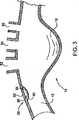
ここで図3を参照すると、図1の大動脈12の大動脈弓の動脈瘤領域について、大動脈壁に加えられる動脈瘤の影響は明瞭となるように切取り図で例示されている。この図では、動脈瘤嚢18が存在している位置は、大動脈12において、心臓の中間部(図示されていないが、図3では左方向)で支脈動脈52、54、56に隣接した部位である。また、大動脈12には切開領域58が存在しているが、この領域では、支脈動脈52、54、56の位置に隣接している(その上流側の)大動脈の位置で、血管の内側壁(層)60が血管の外側壁(層)62から引き離されている。また、内側大動脈壁(層)60には破裂箇所64が存在しており、体血圧の下ではこの破裂箇所を通った血液が、大動脈壁の内側層60と外側層62の間に形成された空隙66に達する。従って、このような大動脈の諸症状を治療するために、ステント・グラフトは動脈瘤嚢18を越えた先の位置まで跨る合成血流管腔を形成し、破裂箇所64を通って血液が供給されるのを封鎖する必要があり、また、切開部が設けられた大動脈の内側壁層60と外側壁層62を一緒に圧迫するような構成になっている。 Referring now to FIG. 3, the aneurysm region of the aortic arch of the
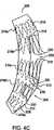
図4A、図4B、図4C、図4Dは本発明によるステント・グラフトの各種実施形態の側面図であり、これらステント・グラフトは動脈瘤嚢18および破裂箇所64を封鎖すると同時に、破裂箇所64に隣接した位置で大動脈の内側壁層60と外側壁層62を一緒に圧迫することができる。これらの図に例示されているステント・グラフトの各実施形態において、提示されている合成血流管腔は、動脈瘤嚢18を迂回または隔離し、更に同様に、切開された大動脈壁を支脈動脈52、54、56に隣接した位置で封鎖すると同時に、支脈動脈52、54、56に血液が流れ込むことができるようにする。一般に、ステント・グラフトの各種実施形態は、1個の窓が3本の支脈動脈の位置に跨って構成されているもの(図4B)と、1本の支脈動脈ごとに個別に窓が設けられた構成のもの(図4A)と、1個の窓が3本の支脈動脈のうちの1本の支脈動脈に用立てられ、もう1個の第2の窓が残り2本の支脈動脈に用立てられる構成のもの(図4Cおよび図4D)とを含むものと思量される。 4A, 4B, 4C, and 4D are side views of various embodiments of the stent-graft according to the present invention, which seal the
まず図4Bを参照すると、一連のステント22a、22b、…、22fが円筒状の枠に形成されたステント・グラフトのグラフト部24に1個の窓32が設けられ、グラフト部がステント22a、22b、…、22fを覆って配置されているのが全体的に例示されている。ステント・グラフト20を形成するために、複数のステント22a、22b、…、22fが形成されて、後段でより詳細に説明される管状グラフト部24の構造体に固着される必要がある。ステント22a、22b、…、22fを形成するために、図4(図4Aから図4D)に例示されている各実施形態では、ニチノール製のワイヤ23が図5に例示されているようなジグザグパターンに形成される。この構成では、これにより複数の千鳥格子状の対向する頂点対26aと26b、26cと26d…が直状部(支柱)28a、28b、28c、28d…によって互いに離隔されて形成され、両端30a、30bで終端している。図5に例示されているように形成されてしまうと、ジグザグ状ワイヤは図6に例示されているようなフープに成形され(図6では複数のフープ状ステントが例示されている)、両端部30a、30bが接合されてステント22aなどのステントを個々に形成する。 Referring first to FIG. 4B, a
図4Bのステント・グラフト20のグラフト部24を形成するために、動脈瘤嚢18を隔離するのに望ましい長さと直径を備えているとともに、図3に参照番号52、54、56と示された支脈動脈に跨るのに十分な長さを備えている、管状織物の生体適合性ポリエステルの長尺部材が洗濯され、この織物部材を切りとって、図4Bに例示されているような切り抜かれた窓32を形成する。この窓の長さと幅は、ステント・グラフト20が大動脈12の動脈瘤に配備された時に、窓32が大動脈12から支脈動脈52、54、56の開口部に跨り、しかも、窓に周方向に隣接しているグラフト材24の一部が大動脈壁を押圧して封鎖することで、図7に例示されているように、動脈瘤嚢18への血流を排除するのを確実にするように選択される。窓32の切断端縁を封鎖するために、そこに隣接している繊維部材には、素材をわずかに改質させる、すなわち、焼灼するのに十分な温度が加えられる。グラフトを形成している管状の織物繊維部材は単体の素材片であってもよいし、複数の素材片が縫合わされたり、それ以外の方法で一緒に付着されたものであってもよい。窓32が切り抜かれて、または、成形によりグラフト材ができあがると、残余のグラフト材が第1フープ21および第2フープ23を形成するとともに、両フープの間の下側すなわち窓32の反対側に延びている差渡し半周囲部25を形成する。次に、ステント22a、22b、…、22fは圧縮されてグラフト部24の内側に納められ、グラフト部24を形成している素材の内側面を押圧して膨らむことができるようにされる。ステント22a、22b、…、22fは各々が隣接するグラフト材に個別に縫い付けられて、ステント22a、22b、…、22fをグラフト部24に固着する。図4Bに例示されているように、ステント22aは第1フープ21によって形成されたグラフト部24の包囲部の中に配置されて完全に支保され、また、ステント22fは第2フープ23によって形成されたグラフト部24の包囲部の中に配置されて完全に支保されるが、ステント22b、22c、22d、22eを配置するにあたり、それぞれの一部が窓32の周囲を巡って延びるように図っているが、その位置はグラフト材が除去されて窓34を形成する位置を実質的に真似た位置にあたり、グラフト材が実際は除去されたのにも関わらず除去されずに窓34を形成したかのように思われる。ステント22bから22eは縫い付けによってステント・グラフトに維持され、または、それ以外の方法で半周囲部25に取付けられる。これに加えて、ステント22a、22b、…、22fを含んでいるワイヤと同じ素材で同じ直径の差渡しワイヤ(接続バー)27が互いに隣接し合うステントとステントの間に配備され、通例は、互いに隣接し合う頂点と頂点の間に配備されるが、ステント22aとステント22bの間に見られるように、ステント22a、22b、…、22fの周辺部を巡る3つまたは4つの位置に置かれてからかしめられ、または、かしめ以外の方法で、その位置に固着され、ステント・グラフトのステント対の間の位置の付加的な剛性を維持している。これ以外にも、拡張抑制式のフープワイヤまたは高強度、高耐性のファイバー部材(図示せず)を採用して、グラフトの開放領域に設置されたステントが胸部側面開放ステント・グラフトの管状形状の範囲を実質的に越えて拡張することがないようにすることを確実にし、この場合の胸部側面開放ステント・グラフトの直径は、その長尺部沿いにずっと、第1フープ21および第2フープ23を包囲しているグラフト部24に近似したものとなる。拡張抑制式のフープワイヤは開口部内で個々のステントに縫い付けられてもよいし、または、かしめられてもよいし、或いは、可撓性の格子状加工品の一部となって、管状構造体が大動脈弓に対して確保する必要がある程度の屈曲性を示すことができるようにしながら、尚且つ、大動脈弓に形状が一致するとともに大動脈弓の中を通って大動脈そのものを擬態する湾曲円筒部材の拘束領域の外側で、被せ部材の一部が望ましくない位置で終端したり、望ましくない形状になってしまう可能性を最小限に抑えるようにしてもよい。 4 has the desired length and diameter for isolating the
図4Bのステント・グラフト20は、図7では配備状態に例示されており、ここでは、窓34が支脈動脈52、54、56と整合して、ステント・グラフト20のグラフト部24のどの部分も、大動脈12と支脈動脈52、54、56のうちのいずれか1本の支脈動脈との交差部に全く被さることがないように図っている。ステント・グラフト20の両端のフープ21、23は内側大動脈壁60に適合押圧して、ステント・グラフトと大動脈壁との界面を封鎖し、また、移植片材24を切り抜いた窓32の開口部に隣接しているグラフト差渡し半周囲部25の一部も同様に、大動脈内側壁60を拡張押圧して封鎖することで、ステント・グラフト20の内部から動脈瘤嚢18に血液が入るのを遮断している。これに加えて、大動脈の切開領域58に被さったステント・グラフト20の一部は大動脈12の内側壁層60と外側壁層62を一緒に押圧し、上記と同様に、大動脈の内側壁60の破裂箇所64を封鎖する。斯くして、大動脈12を通る血流は動脈瘤嚢18から排除され、切開部領域58は破裂箇所64を通って鮮血が送られてくるのを遮断し、大動脈の内側壁および外側壁12を一緒に押圧するが、そうしなければ切開部領域58で両壁が分離する。 The stent-
図4Bに例示されているステント・グラフト20を使用することに内在する1つの問題点は、ステント22b、22c、22d、22eの一部が支保されていない部分が相互に接触することであり、すなわち、ステントの外向き拡張の全部がグラフト材のフープによって制限されず、大動脈12の壁によっても制限されないようなステント配備状態になることである。このように一部が支保されないままのステント22b、22c、22d、22eが、配備時には十分の周方向力を供与して、窓32に隣接している差渡し半周囲部25の各部を大動脈の内側壁60に隣接した部位から封鎖しなければならず、尚且つ、これらステントは大動脈壁60に過負荷を与えたり、大動脈壁の中で拡張し過ぎて、大動脈壁60に損傷を引き起こすようなことになってはいけない。図4Bに例示されている実施形態では、窓32の内側に設置されているステント22b、22c、22d、22eは、包囲されていないために、一部が抑制されておらず、従って、ステント22aやステント22fとは異なり、グラフト部24によって完全に拘束されて圧縮されるわけではない。このように、ステント22b、22c、22d、22eは拡張し過ぎて大動脈12の壁に入り込み、損傷を与える恐れがある。特に、ステント22b、22c、22d、22eが拡張し過ぎた場合には、頂点26aのような頂点が大動脈12の壁を刺し通したり、破裂させたりするという危険が存在する。このようなことが起こるのを防ぐために、(前段で説明したフープワイヤ、格子状加工部、または、その両方の構成が採用されないという条件では)グラフト部によって一部が抑制されていないステント22b、22c、22d、22eの周囲長さを、グラフト部によって抑制されているステント22aおよびステント22fの周囲長さよりも短くするとよい。抑制されているステント22a、22fの周囲長さは、これらステントが配置されることになるグラフト部24の領域におけるグラフト部の内側周囲長さよりも長くなるのが好ましく、すなわち、第1フープ21および第2フープ23と、一部が抑制されていないステント22b、22c、22d、22eの周囲長さは、ステント22aまたはステント22fによって偏倚されていない状態、または、条件のグラフト部24の内側周囲長さと、ほぼ同じであるか、或いは、前記グラフト部24の内側周囲長さよりも僅かに小さいのが好ましい。従って、ステント22b、22c、22d、22eの最大拡張寸法は、グラフト部24の非束縛時の周囲長さ、すなわち、偏倚されていない周囲長さとほぼ同じであり、このように、ステント22b、22c、22d、22eが拡張し過ぎるのが防止されていてながらも、ステント22b、22c、22d、22eによって大動脈12の壁に対して十分な力が放射方向に及ぼされ、窓32に隣接した部分で半周囲部25が大動脈12の壁に接触する位置で、ステント・グラフト20の差渡し半周囲部25に大動脈壁を封鎖させる。 One problem inherent in using the stent-
ここで図4Aを参照すると、本発明によるまた別な実施形態が例示されているが、ここでは、図4Bに例示されている1個の窓32がステント・グラフト100に設けられた複数の個別の窓102、104、106と置換されているが、これら窓は個々の差渡しが大動脈12を起点に延びる支脈動脈52、54、56の各々の開口部の長さである。このような窓を形成するために、グラフト材110は、動脈瘤嚢18に跨って延びるのに十分であるとともに動脈瘤嚢の両側で大動脈壁組織を使ってステント・グラフト100を封鎖することができるようにするのに十分な長さを有しているが、管状壁108から3つの略矩形の部分を切取るという処理が更に施されている。窓102、104、106は各々がグラフト材110に配置されており、ステント・グラフト100の配備時のそれぞれの窓の位置は、支脈動脈52、54、56が大動脈12と交差する3点のうちのどれか1つの位置に一致している。ここでもまた、ステント・グラフト20については、グラフト材110の切り抜きの位置は熱焼灼されて、端のほつれが防止される。3つの窓102、104、106を切り抜くことで、これらの窓に長軸線方向に隣接して、グラフト材110の一連の切れ目無く続くフープを設けることができる。これらのフープは、入口フープ112、出口フープ114、第1の中間フープ116、および、第2の中間フープ118を含んでいる。窓102は入口フープ112と第1の中間フープ116の間に配置されており、窓104は第1の中間フープ116と第2の中間フープ118の間に配置されており、窓106は第2の中間フープ118と出口フープ114の間に配置されている。 Referring now to FIG. 4A, yet another embodiment in accordance with the present invention is illustrated, where a plurality of
ステント・グラフト100を準備するために、図5および図6を参照しながら本件に記載するステントと同じ形状のステント120がグラフト材100の内側に配置されるが、グラフト材には窓102、104、106が事前に形成されている。図示されているステント・グラフト100の構成では、5個のステント120a、120b、120c、120d、120eが使用されている。ステント120aおよびステント120eは仮想線で示されており、入口フープ112および出口フープ114の内側に完全に受け入れられたうえに、これらフープによって抑制される。ステント120bは窓102を跨いで延びているが、ステントの対向する頂点122、124は入口フープ112と第1の中間フープ116の内側に受け入れられるとともにこれらによって抑制される。同様に、ステント120cは窓104に跨るように配置されて、ステントの対向する頂点122、124は第1の中間フープ116と第2の中間フープ118の内側に配置されるとともにこれらによって抑制される。同様に、ステント120dは窓106を跨いで延びており、このステントの対向する頂点122、124は第2の中間フープ118および出口フープ114の内側に配置されるとともにこれらによって抑制される。図4Bのステント・グラフト20の構成については、差渡しワイヤは、例えばステント120aとステント120bなどのような互いに隣接し合うステント対の間に配備することができる。 To prepare the stent-
ステント・グラフト20の構造と比較した場合、フープで抑制されたステント22aおよびステント22fはフープで抑制されていないステント22b、22c、22d、22eとは異なる寸法にする必要があるが、フープ112〜118によって供与される抑制能力とステント120b〜120dの頂点122、124をフープ112〜118の内側に設置することで、窓102を横断してステント120b〜120dが拡張し過ぎるのを防止するのに役立ち、従って、ステント・グラフト100の全体に亘って周囲長さが等しいステントを使用することができる。これに加えて、フープ112〜118は付加的な封鎖能力および押圧能力を供与することで、支脈動脈52、54、56に隣接しているとともにこれらの支脈動脈の中間にある大動脈壁を封鎖押圧するが、これは、図8で分かるように動脈瘤を患った大動脈にステント100が配備されているのが例示されているとおりである。しかしながら、個々の窓102、104、106を採用するには、窓の各々の位置が支脈動脈の位置に一致するのを確実にするにあたり、配備中に一層の精度を必要とする。 When compared with the structure of the stent-
ここで図4Cを参照すると、大動脈弓の動脈瘤を治療するのに有用なステント・グラフト200のまた別な実施形態が例示されている。この実施形態では、ステント・グラフト200には2個の窓202、204が設けられており、第1の窓202の差渡し寸法は支脈動脈52、54(図3に例示されているような動脈)を跨ぐ寸法に設定されており、これよりも小さい第2の窓204の差渡し寸法は支脈動脈56が大動脈12(図3に例示されているような動脈)と交差する位置を跨ぐ寸法に設定されている。図4Aおよび図4Bの実施形態については、この実施形態のステント・グラフト200は、動脈瘤嚢18(図3に例示されている嚢など)を跨いで延びるのに十分な長さを有しているとともに、配備時に大動脈12の壁を封鎖押圧するのに十分な直径を有している管部分の長さがあるグラフト材208に窓202、204を切り抜くことによって形成される。窓202は入口フープ210と中間フープ212の間に配置される。窓204は中間フープ212と出口フープ214の間に配置されており、フープ210、212、214は各々がグラフト材の切れ目無く続く周方向ループから形成される。この実施形態では、図5および図6に関して例示および説明された構成の5個のステント216a、216b、216c、216d、216eが使用される。ステント216aは入口フープの内側に完全に受け入れられ、ステント216eは出口フープ214の内側に完全に受け入れられる。2個のステント216b、216cは窓202に配置され、ステント216bの頂点218が入口フープ210の内側に受け入れられるとともにこれによって抑制され、ステント216bの頂点220は窓202の内側にあって抑制されておらず、ステント216cの頂点220は中間フープ212の内側に受け入れられてこれによって抑制されるが、ステント216cの頂点218は窓202の内側で抑制されない。ステント216a、216b、216c、216d、216eは各々がステント・グラフト200に固着されるが、その手段として好ましいのは、これらステントをグラフト材210の隣接している部分に縫い付けることである。同様に、図示されてはいないが、差渡しワイヤを使用して、固定された長手方向の関係または互いから離隔された関係でステント216a、216b、216c、216d、216eを固着することができるとともに、付加的な輪形張り強度または放射方向強度をステント・グラフと200の構造体に供与することができる。ステント216dは第2の窓204を跨いで延びており、ステント216dの対向する頂点218、220は中間フープ212と出口フープ214のそれぞれの内側に受け入れられて、これらによって抑制される。 Referring now to FIG. 4C, another embodiment of a stent-
図4Bのステント・グラフト20については、ステント216bおよびステント216cは少なくとも一部が抑制されない。よって、格子状加工部材のフープ状の拡張抑制構造体(前段までに説明した)と抑制されていないステント216b、216cの寸法は、残余のステント216a、216d、216eの周囲長さよりも僅かに小さい周囲長さの寸法に設定されるのが好ましいが、これは、ステントによって偏倚されていないグラフト材208の周囲長さに概ね等しい。動脈瘤の患部がある大動脈12に配備されると、窓202は支脈動脈52、54(図3)の大動脈との交差位置に跨って延び、窓204は支脈動脈56の位置に跨って延びる。これに代わる例として、ステント312cおよびステント312dは完全には抑制されず、すなわち、これらステントの頂点は隣接するフープの内側に挿入されず、図4Bのステント・グラフト20に関して先に論じたのと同様に、これらステントの周囲長さはステント216a、216d、216eの周囲長さよりも小さい。同様に、また別なステントが中間フープ212に包囲されて配置されて、この中間フープによって完全に抑制されるようにしてもよい。 For the stent-
ここで図4Dを参照すると、上行大動脈の動脈瘤を治療するためのステント・グラフトのまた別な実施形態が例示されている。この実施形態では、ステント・グラフト300はグラフト材302の管状長尺部部材を含んでおり、このグラフト材の管状長尺部材には窓304、306が予め設けられており、その具体的な手段として、グラフト材202から矩形部を切り抜いて切断端縁を熱封鎖または熱焼灼してほつれを防ぐ方法がある。窓304の寸法は1本の支脈動脈52と大動脈壁との交差点の部位の寸法と一致するように設定されており、窓306の寸法は2本の支脈動脈54、56の部位の寸法と一致するように設定されている。残余のグラフト材は入口フープ306、中間フープ308、および、出口フープ310を形成している。ステント312a、312b、312c、312d、312eはグラフト材302の管状部に配置されており、その具体的な手段として、グラフト材302の隣接する各部に縫い付けられる方法がある。ステント312a、312b、312c、312d、312eは図5および図6に関して図示および説明されたステントの一般的構成を有しており、ステント312aおよびステント312eは入口フープ306および出口フープ310のそれぞれの内側に完全に配置されてこれらによって抑制される。ステント312bは窓304に跨って延び、ステント312bの対向する頂点316、318は入口フープ306と中間フープ308のそれぞれの内側で抑制されるようになっている。ステント312cおよびステント312dは窓306の内側に配置されて、ステント312cの頂点320は中間フープ308によって抑制され、ステント312cの頂点322は窓306の中で抑制されず、ステント312dはその頂点322が出口フープ310の内側に保持されてそこで抑制されるが、ステント312dの頂点320は抑制されないようになっている。図4Cに例示された構成においてと同様に、抑制されない2個のステント312c、312dは抑制されているステントに比べて周囲長さが小さい構成にされて、ステント312c、312dが拡張し過ぎることによって血流管腔に損傷を与えることを回避している。同様に、差渡しワイヤがステント312aなどのステントの互いに隣接し合うものの間で横方向に延在しているとともにこれらステントに接続される。動脈瘤の障害を罹患している大動脈に配備されると、内側フープ302および外側フープ310は大動脈壁を封鎖押圧し、これと同様に、グラフト材302も偏倚されて、グラフト材が被さっている破裂箇所を封鎖押圧するとともに、グラフト材が被さっている複数の切開領域を一緒に圧迫する。ステント・グラフト200については、ステント312c、312dが抑制されず、図4Bに関して既に説明したように、ステント312a、312b、312eよりも直径が僅かに小さくなる。同様に、付加的なステントは中間フープ308の内側に配置されてこれによって完全に抑制される。 Referring now to FIG. 4D, another embodiment of a stent-graft for treating an ascending aortic aneurysm is illustrated. In this embodiment, the stent-
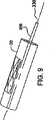
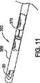
ここで図9から図14を参照すると、ステント・グラフトを配備する実施形態、ここではステント・グラフト20を動脈瘤を患う大動脈弓に配備する実施形態が例示されている。ステント・グラフト20を搬送できるようにするために、ステント・グラフト20は、まず、液体窒素の蒸気中で冷却されてから、図9に例示されているように搬送用カテーテルに被せて設置され、次いで、長軸線330に沿って図10に例示されている状態まで圧縮され、その外径または断面が搬送用鞘部材または搬送用カテーテルの断面形状に適合することができるようにする。ステント・グラフト20を圧縮する前に、ガイドワイヤ鞘部材の中心部材または中間部在、すなわち、カテーテル356は鞘部材の内周側に挿入され、ステント・グラフト20は、圧縮されると、その中を通って延びている中間部356を包囲して組み入れるようになっている。ステント・グラフト20は、図10に例示されているまだ冷えた状態で、尚且つ、その中に中間部356が配置されている状態であったのが、図11に例示されているカテーテル360などのようなカテーテルの外側鞘部材358がステント・グラフトを包囲する位置に移動させられると、静止状態に維持される。中間部356の端部に先細り先端部352が配置され、ガイドワイヤ350は中間部356の中を通り、更に、先細り端部352の開放端を通り抜けることができるようになり(図13)、また、カテーテルの外側鞘部材358に関して中間部356が長軸線方向に移動するのに伴って、先細り先端部352も移動する(図14)。先細り先端部は、動脈瘤を患った大動脈部位までカテーテルを案内することに付随する血管外傷の緩和を助け、また、先細り上の形状になっていることで、外側鞘部材358の直径が連続的であるカテーテルと比べて、動脈瘤部位に至るまでの、管腔が狭くなった領域または直径が小さくなった領域の中を通ってより容易に案内することができる。中間部356は別個の制止部材を含んでおり(図11の外側鞘部材358の切取り図)、この制止部材は外側鞘部材358に関して中間部356の上に長軸線沿いに固定的に設置されており、ステント・グラフト20を配備するために、制止部材370を静止させたままで、外側鞘部材358が後退させるようになっている。従って、外側鞘部材358を後退させることでそこからステント・グラフト20を放出する間、ステント・グラフトは大動脈弓の内側で静止状態のままである。従って、ステント・グラフト20は動脈瘤を患った大動脈弓に容易に配備することができる。 Referring now to FIGS. 9-14, an embodiment for deploying a stent-graft, here an embodiment for deploying the stent-
ステント・グラフト20を動脈瘤部位に搬送するために、切開部(図示せず)が設けられるが、その位置は患者の脚部または鼠蹊部で、しかも、腸骨動脈に達するように設けられるのが好ましく、ガイドワイヤ350は中間部356を通して動脈の中に案内され、動脈に沿って大動脈弓の方向に押される。ガイドワイヤ350は、まず、その端部353が動脈瘤部位14の中を通され、図12に例示されているように、大動脈12の動脈瘤嚢18を越えた先まで達するように挿入される。ガイドワイヤ350を適切に設置することができるようにするために、ガイドワイヤの端部353には放射線不透過性マーカーが設けられて、X線透視法を利用することで端部353をより容易に視認することができるようにするが、ガイドワイヤ350それ自体は、マーカーを使用しなくても済むように、十分にX線透視法により視認することができる。同様に、大動脈12は、ステント・グラフト20を設置することを目的とした患者の準備の一部として、例えば、大動脈12に放射線マーカーをベースにした液体を注入することにより放射線標識が付与され、その結果、医者またはその他の人員がステント・グラフト20を配備することにより、ステント・グラフト20およびカテーテルに相関的に動脈瘤嚢18および支脈動脈52、54、56の位置を容易に視覚化することができるようになる。従って、大動脈12に向けられたX線透視装置を観ることにより、医者はガイドワイヤ350を適切に配置し、その端部を動脈瘤嚢18に隣接して尚且つそれを越えた先に位置決めすることができる。ガイドワイヤ350を使ってカテーテル360を大動脈12の動脈瘤部位14まで案内することができるが、カテーテルはその断面部がガイドワイヤ350よりも実質的に大きい。 In order to deliver the stent-
ガイドワイヤ350が図13に例示されているように配置されてしまうと、カテーテル360は、圧縮状態のステント・グラフト20が図11に関して説明されたようにそこに設けられた鞘部材358の中に配置された状態で、図14に例示されているような動脈瘤嚢18の直ぐ上流側の位置、すなわち、心臓側までガイドワイヤ350を伝って動脈内を案内される。この時点で、ステント・グラフト20を配備することができる。配備前に、ガイドワイヤ鞘部材356の端部の先細り先端部352は、中間部356を押すことにより、図14に例示されているように外側鞘部材358から離れる方向に心臓に向かって僅かに移動させられるが、これにより、外側鞘部材358の開放端を通してステント・グラフト20を露出させることができる。ステント・グラフト20を配備するために、中間部356および制止部材370(図11)を静止状態に保ったままで、外側鞘部材358が引き戻され、すなわち、心臓から離れる方向へ図14の右に引っ張られる。斯くして、ステント・グラフト20は大動脈12で静止位置に維持され、結果的に、ステント・グラフト20は大動脈12に残存させられることになり、図14ではステント・グラフトの第1フープ21が外側鞘部材358から外へ出てきているのが分かる。本発明のステント・グラフトは形状記憶素材から形成されているのが好ましいため、ステント・グラフト20は、膨張装置を必要とせずに、製造時の状態まで拡張し、すなわち、図4Bに例示されているように拡張する。配備中は、ステント・グラフト20はその両端が動脈瘤嚢18に跨って延びるように設置されなければならず、ステント・グラフト20の窓32は3本の支脈動脈52、54、56に跨るように設置されなければならない。これを達成するために、ステント・グラフト20はそこに放射線マーカー(図示せず)が設けられ、支脈動脈52、54、56および動脈瘤嚢18に相対的なこのマーカーの向きと位置を医者が利用することにより、ステント・グラフト20を適切に配備するよう図っている。ステント・グラフト20が大動脈12に回転方向と長軸線方向に適切に設置されてしまうと、外側鞘部材358は図7に例示されているような配備位置にステント・グラフト20を放出するのに十分なだけ後退させられ、ガイドワイヤ350と、先細り先端部352と、中間部356と、外側鞘部材358とを含んでいるカテーテル360は脚部切開部を通して取出される。 Once the
ステント・グラフト20が配備された後で、図15に例示されているように、医者は配備済みのステント・グラフト20の内部でバルーンカテーテル380を使い、造影剤と生理食塩水の混合液を利用してステント・グラフト内に包含されていたバルーン382を膨張させて、ステント・グラフトから外へ張出させ、ステント・グラフト20を僅かに拡張させ、または、完全に拡張させるのを確実にし、更に、グラフト材24の皺をなくする。この処置の間、当然のことながらバルーンは第1フープ21の境界および第2フープ23の境界の内側でしか膨張させられず、ステント22b、22c、22d、22eを拡張し過ぎて大動脈壁に食い込むことがないようにしている。この処置が完了してしまうと、バルーン382は収縮させられて、カテーテル380は取出され、動脈と脚部または鼠蹊部とに設けられた切開部は閉じられる。本件で図示して説明してきたステント・グラフトの実施形態は各々がこの技術を使って配備することができ、そこに設けられた窓は支脈動脈52、54、56と整合させることで、支脈動脈と大動脈12との交差部を遮断してしまうのを回避することができる。 After the stent-
本件で図示して説明してきたステント・グラフトの各種実施形態は、ステント剤として形状記憶素材を使うという条件で説明されてきた。これに代わる例として、上記以外の、例えば、ステンレス鋼のような生体適合性素材を使って、ステント・グラフトのステント部を形成することもできる。この場合、ステント・グラフトを大動脈に配備するのに、膨張用装置をステント・グラフトの内側に設置して使用することが必要となるが、このような膨張用装置を膨張させることで、ステント・グラフトに製造時の形状を取り戻させることができる。このような膨張用装置としてバルーンが考えられるが、バルーンはグラフト部によって規定された周囲長さの範囲内でステント・グラフトの長尺部の中に配置され、その長尺部の両端に跨って延在し、そこから外に伸びている管材に取付けられる。ステント・グラフトが圧縮されてカテーテル内に設置するのに適した形状になると、バルーンがその中に配置され、管材がカテーテルまで送られることで、医者は圧力源を管材に適用し、圧力下で造影剤液またはそれ以外の液体をバルーンに向けて供給し、適切なときにステント・グラフトを膨張させることができるようになる。ステント・グラフトの配備が完了すると、バルーンはカテーテルと一緒に取出される。 Various embodiments of the stent-graft that have been illustrated and described herein have been described on the condition that a shape memory material is used as the stent agent. As an alternative example, a stent portion of a stent / graft can be formed using a biocompatible material other than the above, for example, stainless steel. In this case, in order to deploy the stent-graft in the aorta, it is necessary to install and use an expansion device inside the stent-graft. The graft can be made back to its original shape. A balloon is conceivable as such an inflating device, and the balloon is arranged in the long part of the stent-graft within the range of the perimeter defined by the graft part, and straddles both ends of the long part. Attached to tubing that extends and extends out of it. When the stent-graft is compressed and shaped to be placed in the catheter, the balloon is placed in it and the tubing is sent to the catheter so that the doctor applies a pressure source to the tubing and under pressure. A contrast medium or other liquid can be delivered to the balloon to allow the stent-graft to expand when appropriate. When the stent-graft deployment is complete, the balloon is removed with the catheter.
特殊な実施形態に言及しながら本発明を説明してきたが、本発明の真髄と範囲から逸脱せずに多様な変更を行うことができ、また、本発明の均等物で代用することもできることを、当業者なら、当然、理解するだろう。更に、特定の状況、素材、または、処置を本発明の目的、真髄、および、範囲に適合させるために、多様な修正を行うこともできる。このような修正はすべて、本発明の範囲に入るものと解釈されるべきである。 Although the invention has been described with reference to specific embodiments, it should be understood that various modifications can be made without departing from the spirit and scope of the invention, and that equivalents of the invention can be substituted. Of course, those skilled in the art will understand. In addition, various modifications may be made to adapt a particular situation, material, or procedure to the objective, essence, and scope of the present invention. All such modifications should be construed as falling within the scope of the invention.
本件で言及された引例はすべて、本発明を理解するのを助けるためのものであり、そのような引例はすべてその全体が目的の如何を問わず本件の一部をなすものである。 All references cited in this application are intended to assist in understanding the present invention, and all such references are incorporated herein in their entirety for any purpose.
Claims (7)
Translated fromJapanese管状グラフト材であって、該管状グラフトの一部として形成された第1フープおよび第2フープを有し、前記第1フープと第2フープとは、窓と前記管状グラフトの対応する橋渡し部とによって分離され、前記窓と前記対応する橋渡し部は周方向部分を形成する管状グラフト材と、
前記第1フープ内に受入れられ該第1フープを外方に付勢する第1ステントと、
前記第2フープ内に受入れられ該第2フープを外方に付勢する第2ステントと、
前記橋渡し部に取付けられ、前記窓の周方向部分に沿って延びる少なくとも1のステントと、を備え、
前記第1ステントおよび前記第2ステントの拘束されていない周囲長さが、前記少なくとも1のステントの拘束されていない周囲長さより長く、
前記窓を第1窓部分および第2窓部分に2分割するように配置されたグラフト材の中間フープを更に備えており、
前記第1窓部分は前記大動脈弓の枝動脈の1本と大動脈弓との交差部を跨ぐのに十分な寸法であり、
前記第2窓部分は残余の2本の枝動脈と大動脈弓との交差部を跨ぐのに十分な面積に亘る寸法に設定され、
第4ステントが、前記第1窓部分で、前記グラフト材に取付けられ、
前記ステントは、互いに対向する第1組の頂点と第2組の頂点が設けられたワイヤを有し、
前記第1組の頂点の少なくとも一部は、前記第1フープに受入れられ、前記第1フープによって拘束されており、
前記第2組の頂点の少なくとも一部は、前記中間フープに受入れられ、前記中間フープによって拘束されている、
ことを特徴とするステント・グラフト。A stent-graft that extends across the aneurysm site of the aortic arch adjacent to the branch artery extending from the aortic arch and seals the aneurysm site;
A tubular graft material having first and second hoops formed as part of the tubular graft, the first hoop and the second hoop comprising a window and a corresponding bridging portion of the tubular graft; A tubular graft material that is separated by the window and the corresponding bridging portion forms a circumferential portion;
A first stent received in the first hoop and biasing the first hoop outward;
A second stent received in the second hoop and biasing the second hoop outward;
And at least one stent attached to the bridging portion and extending along a circumferential portion of the window;
The unconstrained perimeter of the first stent and the second stent is greater than the unconstrained perimeter of the at least one stent;
An intermediate hoop of graft material arranged to divide the window into a first window portion and a second window portion;
The first window portion is sized to span the intersection of one of the branch arteries of the aortic arch and the aortic arch;
The second window portion is set to a size that covers an area sufficient to straddle the intersection of the remaining two branch arteries and the aortic arch,
A fourth stent is attached to the graft material at the first window portion;
The stent has a wire provided with a first set of apexes and a second set of apexes facing each other;
At least a portion of the first set of vertices is received by the first hoop and restrained by the first hoop;
At least a portion of the second set of vertices is received by and constrained by the intermediate hoop;
A stent / graft characterized by that.
請求項1に記載のステント・グラフト。A plurality of substantially identical stents attached to the bridge and extending along a circumferential portion of the window;
The stent-graft according to claim 1.
請求項1に記載のステント・グラフト。The at least one stent and the fifth stent are attached to the bridging portion and extend along a circumferential portion of the window;
The stent-graft according to claim1 .
請求項3に記載のステント・グラフト。A sixth stent is received in the intermediate hoop and biases the intermediate hoop outward;
The stent-graft according to claim3 .
前記少なくとも1のステントの前記第1の頂点は、前記中間フープに受入れられ、前記中間フープによって拘束され、
前記第5ステントの前記第2の頂点は前記第2フープに受入れられ、前記第2フープによって拘束される、
請求項3に記載のステント・グラフト。The at least one stent and the fifth stent comprise a first vertex set and a second vertex set facing each other;
The first apex of the at least one stent is received in and constrained by the intermediate hoop;
The second apex of the fifth stent is received in the second hoop and restrained by the second hoop;
The stent-graft according to claim3 .
前記第1窓部分と前記第2窓部分と前記第3窓部分とは各々が、前記大動脈弓の枝動脈の1本と大動脈弓との交差部を跨ぐような寸法および位置に設定されている、
請求項1に記載のステント・グラフト。The stent-graft further comprises a first intermediate hoop and a second intermediate hoop of graft material that divide the window into a first window portion, a second window portion, and a third window portion,
Each of the first window portion, the second window portion, and the third window portion is set to a size and a position so as to straddle the intersection of one of the branch arteries of the aortic arch and the aortic arch. ,
The stent-graft according to claim 1.
前記第3ステント、第4ステント、第5ステントは、互いに対向する第1の頂点の組と第2の頂点の組とを有し、
前記第3ステントは前記第1窓を跨ぐ関係で配置され、
前記第3ステントの前記第1の頂点の組は、前記第1フープ内で延び、前記第1フープによって拘束され、
前記第3ステントの前記第2の頂点の組は前記第1中間フープ内で延び、前記第1中間フープによって拘束され、
前記第4ステントは前記第2窓に受入れられ、前記第4ステントの前記第1の頂点の組は前記第1中間フープに受入れられ、前記第4ステントの前記第2の頂点の組は前記第2中間フープに受入れられ、
前記第5ステントは前記第3窓に受入れられ、前記第5ステントの前記第1の頂点の組は前記第2中間フープに受入れられ、前記第5ステントの前記第2の頂点の組は前記第2フープに受入れられる、
請求項6に記載のステント・グラフト。The at least one stent includes three stents, a third stent, a fourth stent, and a fifth stent;
The third stent, the fourth stent, and the fifth stent have a first vertex set and a second vertex set that face each other.
The third stent is disposed in a relationship straddling the first window;
The first apex set of the third stent extends within the first hoop and is constrained by the first hoop;
The second set of apexes of the third stent extends within the first intermediate hoop and is constrained by the first intermediate hoop;
The fourth stent is received in the second window, the first apex set of the fourth stent is received in the first intermediate hoop, and the second apex set of the fourth stent is the first window. 2 accepted in the intermediate hoop,
The fifth stent is received in the third window, the first vertex set of the fifth stent is received in the second intermediate hoop, and the second vertex set of the fifth stent is the first window. Accepted in 2 hoops,
The stent-graft according to claim6 .
Applications Claiming Priority (3)
| Application Number | Priority Date | Filing Date | Title |
|---|---|---|---|
| US71359505P | 2005-09-01 | 2005-09-01 | |
| US60/713,595 | 2005-09-01 | ||
| PCT/US2006/034340WO2007028086A2 (en) | 2005-09-01 | 2006-09-01 | Methods and apparatus for treatment of thoracic aortic aneurysms |
Publications (3)
| Publication Number | Publication Date |
|---|---|
| JP2009506842A JP2009506842A (en) | 2009-02-19 |
| JP2009506842A5 JP2009506842A5 (en) | 2009-10-15 |
| JP4901872B2true JP4901872B2 (en) | 2012-03-21 |
Family
ID=37638030
Family Applications (1)
| Application Number | Title | Priority Date | Filing Date |
|---|---|---|---|
| JP2008529338AExpired - Fee RelatedJP4901872B2 (en) | 2005-09-01 | 2006-09-01 | Method and apparatus for treating thoracic aortic aneurysm |
Country Status (6)
| Country | Link |
|---|---|
| US (1) | US8292949B2 (en) |
| EP (1) | EP1933763B1 (en) |
| JP (1) | JP4901872B2 (en) |
| DE (1) | DE602006019753D1 (en) |
| ES (1) | ES2360185T3 (en) |
| WO (1) | WO2007028086A2 (en) |
Families Citing this family (61)
| Publication number | Priority date | Publication date | Assignee | Title |
|---|---|---|---|---|
| US7147661B2 (en) | 2001-12-20 | 2006-12-12 | Boston Scientific Santa Rosa Corp. | Radially expandable stent |
| US7763063B2 (en) | 2003-09-03 | 2010-07-27 | Bolton Medical, Inc. | Self-aligning stent graft delivery system, kit, and method |
| US9198786B2 (en) | 2003-09-03 | 2015-12-01 | Bolton Medical, Inc. | Lumen repair device with capture structure |
| US20080264102A1 (en) | 2004-02-23 | 2008-10-30 | Bolton Medical, Inc. | Sheath Capture Device for Stent Graft Delivery System and Method for Operating Same |
| US11596537B2 (en) | 2003-09-03 | 2023-03-07 | Bolton Medical, Inc. | Delivery system and method for self-centering a proximal end of a stent graft |
| US11259945B2 (en) | 2003-09-03 | 2022-03-01 | Bolton Medical, Inc. | Dual capture device for stent graft delivery system and method for capturing a stent graft |
| US8292943B2 (en) | 2003-09-03 | 2012-10-23 | Bolton Medical, Inc. | Stent graft with longitudinal support member |
| US8500792B2 (en) | 2003-09-03 | 2013-08-06 | Bolton Medical, Inc. | Dual capture device for stent graft delivery system and method for capturing a stent graft |
| US20070198078A1 (en) | 2003-09-03 | 2007-08-23 | Bolton Medical, Inc. | Delivery system and method for self-centering a Proximal end of a stent graft |
| ES2624595T3 (en) | 2007-03-05 | 2017-07-17 | Endospan Ltd | Bifurcated, supportive, expandable endoluminal grafts with multiple components and methods for use |
| JP5230616B2 (en)* | 2007-05-21 | 2013-07-10 | 川澄化学工業株式会社 | Stent graft placement device, stent graft and fixation tip |
| CN101965162B (en) | 2007-12-15 | 2014-12-10 | 恩多斯潘有限公司 | Extra-vascular wrapping for treating aneurysmatic aorta in conjunction with endovascular stent-graft and methods thereof |
| CN102076281B (en) | 2008-06-30 | 2014-11-05 | 波顿医疗公司 | Systems and methods for abdominal aortic aneurysm |
| US20100049307A1 (en)* | 2008-08-25 | 2010-02-25 | Aga Medical Corporation | Stent graft having extended landing area and method for using the same |
| WO2010080427A1 (en)* | 2008-12-18 | 2010-07-15 | Med Institute, Inc. | Stents and stent grafts |
| EP3284447B1 (en)* | 2009-03-13 | 2020-05-20 | Bolton Medical Inc. | System for deploying an endoluminal prosthesis at a surgical site |
| US20110054587A1 (en)* | 2009-04-28 | 2011-03-03 | Endologix, Inc. | Apparatus and method of placement of a graft or graft system |
| CA3009244C (en) | 2009-06-23 | 2020-04-28 | Endospan Ltd. | Vascular prostheses for treating aneurysms |
| WO2011004374A1 (en) | 2009-07-09 | 2011-01-13 | Endospan Ltd. | Apparatus for closure of a lumen and methods of using the same |
| CN102740807B (en) | 2009-11-30 | 2015-11-25 | 恩多斯潘有限公司 | Multi-component stent-graft system for implantation into vessels with multiple branches |
| EP2509535B1 (en) | 2009-12-08 | 2016-12-07 | Endospan Ltd | Endovascular stent-graft system with fenestrated and crossing stent-grafts |
| WO2011080738A1 (en) | 2009-12-31 | 2011-07-07 | Endospan Ltd. | Endovascular flow direction indicator |
| US9468517B2 (en) | 2010-02-08 | 2016-10-18 | Endospan Ltd. | Thermal energy application for prevention and management of endoleaks in stent-grafts |
| EP2544623B1 (en)* | 2010-03-09 | 2018-01-10 | Solinas Medical Inc. | Self-closing devices |
| AU2010201067B1 (en) | 2010-03-19 | 2011-06-09 | Cook Incorporated | Thoracic stent graft |
| US9788933B2 (en)* | 2010-10-29 | 2017-10-17 | Cook Medical Technologies Llc | Medical device delivery system and deployment method |
| FR2970410B1 (en) | 2011-01-13 | 2013-02-08 | Ct Hospitalier Universitaire Nimes | THORACIC ENDOPROTHESIS IN T |
| CA2826022A1 (en) | 2011-02-03 | 2012-08-09 | Endospan Ltd. | Implantable medical devices constructed of shape memory material |
| WO2012111006A1 (en) | 2011-02-17 | 2012-08-23 | Endospan Ltd. | Vascular bands and delivery systems therefor |
| WO2012117395A1 (en) | 2011-03-02 | 2012-09-07 | Endospan Ltd. | Reduced-strain extra- vascular ring for treating aortic aneurysm |
| US8574287B2 (en) | 2011-06-14 | 2013-11-05 | Endospan Ltd. | Stents incorporating a plurality of strain-distribution locations |
| US8951298B2 (en) | 2011-06-21 | 2015-02-10 | Endospan Ltd. | Endovascular system with circumferentially-overlapping stent-grafts |
| US9254209B2 (en) | 2011-07-07 | 2016-02-09 | Endospan Ltd. | Stent fixation with reduced plastic deformation |
| US9314328B2 (en) | 2011-08-16 | 2016-04-19 | W. L. Gore & Associates, Inc. | Branched stent graft device and deployment |
| FR2979228B1 (en) | 2011-08-22 | 2014-08-29 | Ct Hospitalier Universitaire Nimes | UNIVERSAL AORTIC ENDOPROTHESIS |
| FR2979229A1 (en) | 2011-08-22 | 2013-03-01 | Ct Hospitalier Universitaire Nimes | ENDOPROTHESIS FENESTRATION DEVICE |
| US9839510B2 (en) | 2011-08-28 | 2017-12-12 | Endospan Ltd. | Stent-grafts with post-deployment variable radial displacement |
| US9662196B2 (en)* | 2011-09-27 | 2017-05-30 | Cook Medical Technologies Llc | Endoluminal prosthesis with steerable branch |
| US9427339B2 (en) | 2011-10-30 | 2016-08-30 | Endospan Ltd. | Triple-collar stent-graft |
| US9597204B2 (en)* | 2011-12-04 | 2017-03-21 | Endospan Ltd. | Branched stent-graft system |
| DE102012100839A1 (en) | 2012-02-01 | 2013-08-01 | Jotec Gmbh | Intraluminal vascular prosthesis |
| EP2821030B1 (en)* | 2012-02-27 | 2017-12-06 | Hiroshima University | Stent graft |
| EP2846743B1 (en) | 2012-04-12 | 2016-12-14 | Bolton Medical Inc. | Vascular prosthetic delivery device |
| US8968384B2 (en)* | 2012-04-27 | 2015-03-03 | Medtronic Vascular, Inc. | Circumferentially constraining sutures for a stent-graft |
| WO2013171730A1 (en) | 2012-05-15 | 2013-11-21 | Endospan Ltd. | Stent-graft with fixation elements that are radially confined for delivery |
| WO2014059005A1 (en)* | 2012-10-09 | 2014-04-17 | Boston Scientific Scimed, Inc. | Special opening aortic embolic protection device for structural heart procedures |
| US9993360B2 (en) | 2013-01-08 | 2018-06-12 | Endospan Ltd. | Minimization of stent-graft migration during implantation |
| US9668892B2 (en) | 2013-03-11 | 2017-06-06 | Endospan Ltd. | Multi-component stent-graft system for aortic dissections |
| US9439751B2 (en) | 2013-03-15 | 2016-09-13 | Bolton Medical, Inc. | Hemostasis valve and delivery systems |
| WO2015075708A1 (en) | 2013-11-19 | 2015-05-28 | Endospan Ltd. | Stent system with radial-expansion locking |
| WO2015081175A1 (en)* | 2013-11-26 | 2015-06-04 | Children's Medical Center Corporation | Expandable stent valve |
| FR3021208B1 (en)* | 2014-05-23 | 2021-03-12 | Thomas Modine | MITRAL OR TRICUSPID HEART VALVE PROSTHESIS |
| DE102014114747A1 (en)* | 2014-10-10 | 2016-04-14 | Jotec Gmbh | Vascular prostheses system |
| CN106029005B (en) | 2014-12-18 | 2018-01-19 | 恩都思潘有限公司 | The Endovascular stent-graft of horizontal conduit with tired resistance |
| PL3653177T3 (en) | 2015-01-11 | 2022-01-31 | Ascyrus Medical, Llc | Hybrid device for surgical aortic repair |
| US10517711B2 (en) | 2016-04-25 | 2019-12-31 | Medtronic Vascular, Inc. | Dissection prosthesis system and method |
| EP3648705A4 (en) | 2017-07-07 | 2021-03-24 | Endologix LLC | Endovascular graft systems and methods for deployment in main and branch arteries |
| FR3087113B1 (en)* | 2018-10-12 | 2022-04-08 | Ludovic Canaud | STENT-TYPE AORTIC IMPLANT, AND SET OF TWO SUCH IMPLANTS |
| FI3941392T3 (en) | 2019-03-20 | 2025-07-28 | Inqb8 Medical Tech Llc | Aortic dissection implant |
| EP4585192A3 (en) | 2020-06-24 | 2025-10-15 | Bolton Medical, Inc. | Anti-backspin component for vascular prosthesis delivery device |
| FR3123798B1 (en) | 2021-06-10 | 2023-12-22 | Univ Claude Bernard Lyon | Fenestrated Endoprosthesis of the Thoracic Aorta |
Family Cites Families (15)
| Publication number | Priority date | Publication date | Assignee | Title |
|---|---|---|---|---|
| US5330500A (en)* | 1990-10-18 | 1994-07-19 | Song Ho Y | Self-expanding endovascular stent with silicone coating |
| US6030414A (en)* | 1997-11-13 | 2000-02-29 | Taheri; Syde A. | Variable stent and method for treatment of arterial disease |
| AUPP083597A0 (en) | 1997-12-10 | 1998-01-08 | William A Cook Australia Pty Ltd | Endoluminal aortic stents |
| US6398803B1 (en)* | 1999-02-02 | 2002-06-04 | Impra, Inc., A Subsidiary Of C.R. Bard, Inc. | Partial encapsulation of stents |
| US6648913B1 (en) | 1999-06-07 | 2003-11-18 | Scimed Life Systems, Inc. | Guidewire-access modular intraluminal prosthesis with connecting section |
| US6663667B2 (en) | 1999-12-29 | 2003-12-16 | Edwards Lifesciences Corporation | Towel graft means for enhancing tissue ingrowth in vascular grafts |
| JP2004512920A (en)* | 2000-11-17 | 2004-04-30 | エビーシオ・メディカル・デバイセズ・ユーエルシー | Endovascular prosthesis |
| ES2223759T3 (en) | 2001-03-27 | 2005-03-01 | William Cook Europe Aps | AORTIC GRAFT DEVICE. |
| US20040116998A1 (en)* | 2001-11-19 | 2004-06-17 | Raimund Erbel | Endovascular prosthesis |
| EP1487380B1 (en)* | 2002-03-25 | 2008-02-27 | Cook Incorporated | Branched vessel prothesis |
| EP1608293B1 (en)* | 2003-04-03 | 2015-06-03 | Cook Medical Technologies LLC | Deployment system for a branched stent graft |
| DE10337739B4 (en)* | 2003-08-12 | 2009-11-26 | Jotec Gmbh | Stent for implantation in a blood vessel, especially in the area of the aortic arch |
| US7144421B2 (en)* | 2003-11-06 | 2006-12-05 | Carpenter Judith T | Endovascular prosthesis, system and method |
| US20050149168A1 (en)* | 2003-12-30 | 2005-07-07 | Daniel Gregorich | Stent to be deployed on a bend |
| US8048140B2 (en)* | 2004-03-31 | 2011-11-01 | Cook Medical Technologies Llc | Fenestrated intraluminal stent system |
- 2006
- 2006-09-01JPJP2008529338Apatent/JP4901872B2/ennot_activeExpired - Fee Related
- 2006-09-01EPEP06814103Apatent/EP1933763B1/ennot_activeNot-in-force
- 2006-09-01WOPCT/US2006/034340patent/WO2007028086A2/enactiveApplication Filing
- 2006-09-01DEDE602006019753Tpatent/DE602006019753D1/enactiveActive
- 2006-09-01ESES06814103Tpatent/ES2360185T3/enactiveActive
- 2007
- 2007-05-18USUS11/750,678patent/US8292949B2/enactiveActive
Also Published As
| Publication number | Publication date |
|---|---|
| JP2009506842A (en) | 2009-02-19 |
| EP1933763B1 (en) | 2011-01-19 |
| WO2007028086A2 (en) | 2007-03-08 |
| WO2007028086A8 (en) | 2008-08-07 |
| WO2007028086A3 (en) | 2007-05-10 |
| US8292949B2 (en) | 2012-10-23 |
| US20070233229A1 (en) | 2007-10-04 |
| DE602006019753D1 (en) | 2011-03-03 |
| EP1933763A2 (en) | 2008-06-25 |
| ES2360185T3 (en) | 2011-06-01 |
Similar Documents
| Publication | Publication Date | Title |
|---|---|---|
| JP4901872B2 (en) | Method and apparatus for treating thoracic aortic aneurysm | |
| KR101030945B1 (en) | Deliverable stent in the vascular system to strengthen vascular abnormalities | |
| JP4394125B2 (en) | Multi-lumen prosthesis system and method | |
| KR100521671B1 (en) | Endovascular prosthetic device, and method of use | |
| US8900287B2 (en) | Intravascular deliverable stent for reinforcement of abdominal aortic aneurysm | |
| RU2179421C2 (en) | Method for setting intralumen transplant by using guiding wire and catheter | |
| JP4307086B2 (en) | Prosthesis for bilateral stretching and distribution method | |
| JP2022028723A (en) | Systems and methods for treating aneurysms | |
| JP4354105B2 (en) | Precursor stent and aortic graft provided with the same | |
| US9149381B2 (en) | Apparatus and method of placement of a graft or graft system | |
| JP4152072B2 (en) | Prosthesis | |
| AU766582B2 (en) | Implantable stroke preventing device | |
| CA2565106C (en) | Flexible vascular occluding device | |
| JP4522258B2 (en) | Device for managing an abdominal aortic aneurysm | |
| JP4097897B2 (en) | Extensible stent device | |
| JP6290097B2 (en) | Intracavity artificial blood vessel | |
| JP5941583B2 (en) | Method and apparatus for endovascular treatment of aortic lesions | |
| US20150005868A1 (en) | Endovascular prosthesis | |
| JP2023533277A (en) | Axially compressible and expandable bare stent | |
| CN113893071B (en) | A bare stent compressible in the axial direction | |
| US10849732B2 (en) | Prosthesis for treating abdominal aortic aneurysm and method |
Legal Events
| Date | Code | Title | Description |
|---|---|---|---|
| A521 | Request for written amendment filed | Free format text:JAPANESE INTERMEDIATE CODE: A523 Effective date:20090825 | |
| A621 | Written request for application examination | Free format text:JAPANESE INTERMEDIATE CODE: A621 Effective date:20090825 | |
| A977 | Report on retrieval | Free format text:JAPANESE INTERMEDIATE CODE: A971007 Effective date:20110517 | |
| A131 | Notification of reasons for refusal | Free format text:JAPANESE INTERMEDIATE CODE: A131 Effective date:20110523 | |
| A601 | Written request for extension of time | Free format text:JAPANESE INTERMEDIATE CODE: A601 Effective date:20110823 | |
| A602 | Written permission of extension of time | Free format text:JAPANESE INTERMEDIATE CODE: A602 Effective date:20110830 | |
| A521 | Request for written amendment filed | Free format text:JAPANESE INTERMEDIATE CODE: A523 Effective date:20111124 | |
| TRDD | Decision of grant or rejection written | ||
| A01 | Written decision to grant a patent or to grant a registration (utility model) | Free format text:JAPANESE INTERMEDIATE CODE: A01 Effective date:20111219 | |
| A01 | Written decision to grant a patent or to grant a registration (utility model) | Free format text:JAPANESE INTERMEDIATE CODE: A01 | |
| A61 | First payment of annual fees (during grant procedure) | Free format text:JAPANESE INTERMEDIATE CODE: A61 Effective date:20111227 | |
| R150 | Certificate of patent or registration of utility model | Ref document number:4901872 Country of ref document:JP Free format text:JAPANESE INTERMEDIATE CODE: R150 Free format text:JAPANESE INTERMEDIATE CODE: R150 | |
| FPAY | Renewal fee payment (event date is renewal date of database) | Free format text:PAYMENT UNTIL: 20150113 Year of fee payment:3 | |
| R250 | Receipt of annual fees | Free format text:JAPANESE INTERMEDIATE CODE: R250 | |
| R250 | Receipt of annual fees | Free format text:JAPANESE INTERMEDIATE CODE: R250 | |
| R250 | Receipt of annual fees | Free format text:JAPANESE INTERMEDIATE CODE: R250 | |
| R250 | Receipt of annual fees | Free format text:JAPANESE INTERMEDIATE CODE: R250 | |
| R250 | Receipt of annual fees | Free format text:JAPANESE INTERMEDIATE CODE: R250 | |
| R250 | Receipt of annual fees | Free format text:JAPANESE INTERMEDIATE CODE: R250 | |
| R250 | Receipt of annual fees | Free format text:JAPANESE INTERMEDIATE CODE: R250 | |
| R250 | Receipt of annual fees | Free format text:JAPANESE INTERMEDIATE CODE: R250 | |
| LAPS | Cancellation because of no payment of annual fees |