JP4899805B2 - Video phone equipment - Google Patents
Video phone equipmentDownload PDFInfo
- Publication number
- JP4899805B2 JP4899805B2JP2006302316AJP2006302316AJP4899805B2JP 4899805 B2JP4899805 B2JP 4899805B2JP 2006302316 AJP2006302316 AJP 2006302316AJP 2006302316 AJP2006302316 AJP 2006302316AJP 4899805 B2JP4899805 B2JP 4899805B2
- Authority
- JP
- Japan
- Prior art keywords
- display
- lens
- half mirror
- camera
- image
- Prior art date
- Legal status (The legal status is an assumption and is not a legal conclusion. Google has not performed a legal analysis and makes no representation as to the accuracy of the status listed.)
- Expired - Fee Related
Links
Images


Classifications
- H—ELECTRICITY
- H04—ELECTRIC COMMUNICATION TECHNIQUE
- H04N—PICTORIAL COMMUNICATION, e.g. TELEVISION
- H04N7/00—Television systems
- H04N7/14—Systems for two-way working
- H04N7/141—Systems for two-way working between two video terminals, e.g. videophone
- H04N7/142—Constructional details of the terminal equipment, e.g. arrangements of the camera and the display
- H04N7/144—Constructional details of the terminal equipment, e.g. arrangements of the camera and the display camera and display on the same optical axis, e.g. optically multiplexing the camera and display for eye to eye contact
- H—ELECTRICITY
- H04—ELECTRIC COMMUNICATION TECHNIQUE
- H04N—PICTORIAL COMMUNICATION, e.g. TELEVISION
- H04N7/00—Television systems
- H04N7/14—Systems for two-way working
- H04N7/141—Systems for two-way working between two video terminals, e.g. videophone
- H04N7/142—Constructional details of the terminal equipment, e.g. arrangements of the camera and the display
- H04N2007/145—Handheld terminals
Landscapes
- Engineering & Computer Science (AREA)
- Multimedia (AREA)
- Signal Processing (AREA)
- Two-Way Televisions, Distribution Of Moving Picture Or The Like (AREA)
- Telephone Set Structure (AREA)
- Studio Devices (AREA)
Description
Translated fromJapanese本発明は、テレビ電話装置に関し、特に、例えば携帯電話端末のような小型携帯端末にも搭載可能な小型及び薄型のテレビ電話装置に関する。 The present invention relates to a videophone device, and more particularly to a small and thin videophone device that can be mounted on a small mobile terminal such as a mobile phone terminal.
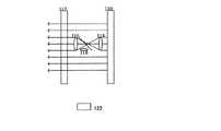
図1は、従来のテレビ電話機能付き携帯電話端末の例を示す図である。携帯電話端末100はディスプレイ102とカメラ104を備え、ディスプレイ102と別の位置にレンズ106が設けられ、カメラ104は、レンズ106を通して、例えば、ユーザの顔などを撮影し、撮影された画像は、通信相手の端末に送信される。このとき、ディスプレイ102には、通信相手の顔が表示されているので、携帯電話端末100のユーザは、ディスプレイ102を見ながら会話を行う。 FIG. 1 is a diagram showing an example of a conventional mobile phone terminal with a videophone function. The mobile phone terminal 100 includes a display 102 and a camera 104, and a lens 106 is provided at a position different from the display 102. The camera 104 photographs a user's face, for example, through the lens 106, Sent to the other party's terminal. At this time, since the face of the communication partner is displayed on the display 102, the user of the mobile phone terminal 100 has a conversation while looking at the display 102.
すなわち、ユーザがディスプレイ102に表示される通信相手の顔を見ているときは、視線はディスプレイ102を向いてしまい、カメラ104によって撮影されるユーザの顔は、別の所を見ているように通信相手側の端末に表示される。このように、ユーザの視線はディスプレイ102の方向を向いており、撮影方向、すなわち、カメラ104のレンズ106に向いていないので、ディスプレイを通して、通信相手との視線が合わず、対話に不自然さが生じる。 That is, when the user is looking at the face of the communication partner displayed on the display 102, the line of sight is facing the display 102, and the user's face photographed by the camera 104 is looking at another place. It is displayed on the terminal of the communication partner. In this way, the user's line of sight faces the direction of the display 102 and does not face the shooting direction, that is, the lens 106 of the camera 104. Occurs.
また、携帯電話端末のカメラ機能で、いわゆる自分自身を撮影する場合も、ディスプレイ102に表示される自分自身の表情などを確認した後、撮影時は、カメラをレンズ106の向きに視線を移す必要がある。このように、テレビ電話装置において、視線を一致させる構成が求められていた。 Also, when photographing a so-called self with the camera function of the mobile phone terminal, it is necessary to check the facial expression displayed on the display 102 and then move the camera to the direction of the lens 106 when photographing. There is. Thus, there has been a demand for a configuration that matches the line of sight in a videophone device.
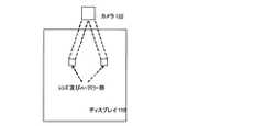
図2は、視線を一致させることができる従来のテレビ電話装置のレンズ及びハーフミラー部の構成例を示す図である。ハーフミラー108をディスプレイ102の手前に配置し、ハーフミラー108が、ディスプレイ102の表示側の光路を透過させるとともに、撮影側の光路を反射させて、レンズ106及びカメラ104の方向に導くことで、ディスプレイ102を見るための視線とレンズ106に向く視線とを一致させることができる。 FIG. 2 is a diagram illustrating a configuration example of a lens and a half mirror unit of a conventional videophone device that can match the line of sight. The half mirror 108 is disposed in front of the display 102, and the half mirror 108 transmits the optical path on the display side of the display 102 and reflects the optical path on the photographing side to guide it in the direction of the lens 106 and the camera 104. The line of sight for viewing the display 102 and the line of sight toward the lens 106 can be matched.
また、下記特許文献1は、ディスプレイの表示をミラーに反射させ、ミラーの一部にカメラ撮影を可能とする半透過窓を設けた装置について開示し、ユーザはそのミラーに反射された表示を見ながら会話することで、視線一致が得られる構成を示している。 Further,
また、下記特許文献2は、投影された画像を表示するスクリーンにカメラ撮影用窓を設けた表示装置について開始、ユーザはそのスクリーンに投影された表示を見ながら会話することで、視線一致を得られる構成を示している。
しかしながら、図2の構成では、視線の不一致は解消することができるが、ディスプレイ102の表示サイズ全体に対応するハーフミラー108を設ける必要があり、その大きさに応じて、装置の奥行きが必要となり、テレビ電話装置を携帯電話端末に組み込む場合、テレビ電話装置の小型化、薄型化の障害となる。 However, in the configuration of FIG. 2, the line-of-sight discrepancy can be eliminated, but it is necessary to provide a half mirror 108 corresponding to the entire display size of the display 102, and the depth of the apparatus is required according to the size. When a video phone device is incorporated into a mobile phone terminal, it becomes an obstacle to miniaturization and thinning of the video phone device.
また、特許文献1においては、ディスプレイの表示をミラーに反射させる必要があるため、ディスプレイとミラーに角度を持たせることができる構造(例えば、折り畳み型の携帯電話端末)にテレビ電話装置の形状が限定される。また、ミラーに反射した画像をのぞき込むようにして使用するため、ディスプレイの使用感が従来の携帯電話端末と大きく異なり、ディスプレイを直視するものに対して、使い勝手が大きく劣る。 Further, in
さらに、特許文献2においては、表示方式に投影方式を採用しており、投影方式以外の表示方式には適用できないので、現在主流の液晶表示には適用できないという問題がある。また、投影スクリーンより手前に投影部が位置する必要があり、テレビ電話装置の形状が限定される(例えば、折り畳み型の携帯電話端末)。 Further, Patent Document 2 employs a projection method as a display method and cannot be applied to a display method other than the projection method, and therefore cannot be applied to a currently mainstream liquid crystal display. In addition, the projection unit needs to be positioned in front of the projection screen, and the shape of the videophone device is limited (for example, a foldable mobile phone terminal).
そこで、本発明の目的は、通信相手との対話中に視線を一致させることができるテレビ電話装置において、小型且つ薄型のテレビ電話装置を提供することにある。 SUMMARY OF THE INVENTION An object of the present invention is to provide a small and thin videophone device that can match the line of sight during a conversation with a communication partner.
また、本発明の目的は、表示方式を問わず、液晶ディスプレイや有機ELディスプレイを備えるテレビ電話装置において、通信相手との対話中に視線を一致させることができる小型且つ薄型のテレビ電話装置を提供することにある。 Another object of the present invention is to provide a small and thin videophone device that can match the line of sight during a conversation with a communication partner in a videophone device including a liquid crystal display or an organic EL display regardless of the display method. There is to do.
上記目的を達成するための本発明のテレビ電話装置の第一の構成は、カメラで撮影した画像を送信し、受信した画像をディスプレイに表示するテレビ電話装置において、前記ディスプレイと所定間隔を隔てて前記ディスプレイの表面を覆うカバー部と、前記カバー部の内側であって前記ディスプレイの表面上に配置され、前記ディスプレイの表面積より小さいハーフミラーと、前記ディスプレイと前記ハーフミラーとの間に配置され、前記ディスプレイの画像に対応する光の一部を前記ハーフミラーに導く凸レンズである第一のレンズと、前記カバー部と前記ハーフミラーとの間に配置され、前記ハーフミラーを透過した光を前記カバー部に導くと共に、前記カバー部の外側からの光を前記ハーフミラーに導く凸レンズである第二のレンズと、前記第二のレンズと前記ハーフミラーとの間に配置され、前記カバー部の外側からの光が前記ハーフミラーで反射した光を前記カメラに導く第三のレンズとを備えることを特徴とする。 In order to achieve the above object, a first configuration of a videophone device according to the present invention is a videophone device that transmits an image taken by a camera and displays the received image on a display, with a predetermined interval from the display. A cover portion covering the surface of the display; a half mirror disposed on the surface of the display inside the cover portion and smaller than a surface area of the display; and disposed between the display and the half mirror; A first lens that is a convex lens that guides a part of light corresponding to an image of the display to the half mirror; and a light that is disposed between the cover portion and the half mirror and transmits the half mirror. And a second lens that is a convex lens that guides light from outside the cover part to the half mirror Wherein said second lens is disposed between the half mirror, characterized in that it comprises a third lens for guiding light the light is reflected by the half mirror from the outside of the cover portion to the camera.
本発明のテレビ電話装置の第二の構成は、上記第一の構成において、前記ディスプレイの画像に対応する光のうち、前記ハーフミラーを透過しないで前記カバー部に達する光の輝度を、前記ハーフミラーを透過する輝度に減衰するためのフィルタを備えることを特徴とする。 According to a second configuration of the videophone device of the present invention, in the first configuration described above, the luminance of the light reaching the cover portion without passing through the half mirror among the light corresponding to the image of the display is changed to the half configuration. A filter is provided for attenuating the brightness to be transmitted through the mirror.
本発明のテレビ電話装置の第三の構成は、上記第一の構成において、前記ハーフミラーは可動にするアクチュエータを備えることを特徴とする。 A third configuration of the videophone device according to the present invention is characterized in that, in the first configuration, the half mirror includes an actuator for making it movable.
本発明のテレビ電話装置の第四の構成は、上位第一の構成において、前記ハーフミラー、前記第一のレンズ、前記第二のレンズ及び前記第三のレンズの組み合わせからなる光学ユニットを2組備え、当該2組の光学ユニットは、前記カバー部の内側であって前記ディスプレイの表面上に水平方向に所定間隔離れて互いに配置され、各光学ユニットの前記第三のレンズは、それぞれ前記カメラに設けられる撮像素子の左半分の領域及び右半分の領域に、各光学ユニットの前記ハーフミラーで反射した光を導くことを特徴とする。 According to a fourth configuration of the videophone device of the present invention, in the upper first configuration, two sets of optical units each including a combination of the half mirror, the first lens, the second lens, and the third lens are provided. The two sets of optical units are arranged inside the cover portion and spaced apart from each other in the horizontal direction on the surface of the display, and the third lens of each optical unit is attached to the camera, respectively. The light reflected by the half mirror of each optical unit is guided to the left half area and the right half area of the image pickup device provided.
本発明によれば、ユーザがディスプレイを見ているときに、そのディスプレイ方向の視線上からユーザの顔を撮影することができるので、通信相手と視線を合わせた自然なテレビ電話が可能となる。 According to the present invention, since the user's face can be photographed from the line of sight in the display direction when the user is looking at the display, a natural videophone that matches the line of sight with the communication partner is possible.
ディスプレイ表面の内側にディスプレイの表面積より十分小さい小型のハーフミラーを設けて撮影するので、テレビ電話装置の小型化、薄型化を実現することができ、携帯電話端末に適用可能となる。 Since a small half mirror that is sufficiently smaller than the surface area of the display is provided on the inside of the display surface, the videophone device can be reduced in size and thickness, and can be applied to a mobile phone terminal.
小型のハーフミラーを使用した場合に、ハーフミラーから反射した光をカメラに導くレンズが、ディスプレイ表面の内側に配置する必要となるが、ディスプレイの表示方向にハーフミラーを挟んで凸レンズを配置する構成とすることで、当該レンズの陰がディスプレイ表面に表示されないようにすることができる。 When a small half mirror is used, the lens that guides the light reflected from the half mirror to the camera needs to be placed inside the display surface, but a convex lens is placed across the half mirror in the display direction of the display. By doing so, the shade of the lens can be prevented from being displayed on the display surface.
テレビ電話装置に用いられるディスプレイは、液晶ディスプレイや有機ELディスプレイなどその種類を問わない。また、カメラの種類(CCDやCMOSなど)も問わないので、既存のディスプレイ、カメラをそのまま利用できるため、コストの上昇を抑えることができる。 The type of display used in the videophone device is not limited, such as a liquid crystal display or an organic EL display. Moreover, since the kind of camera (CCD, CMOS, etc.) is not ask | required, since the existing display and camera can be utilized as they are, the rise in cost can be suppressed.
以下、図面を参照して本発明の実施の形態について説明する。しかしながら、かかる実施の形態例が、本発明の技術的範囲を限定するものではない。 Embodiments of the present invention will be described below with reference to the drawings. However, such an embodiment does not limit the technical scope of the present invention.
図3は、本発明の実施の形態におけるテレビ電話装置のレンズ及びハーフミラー部の第一の構成例を示す図である。本発明のテレビ電話装置は、例えばカメラを内蔵する携帯電話端末であって、携帯電話端末の通信機能により、カメラで撮影した画像データの通信を行う。図3は、携帯電話端末のレンズ及びハーフミラー部の断面図であって、レンズハーフミラー部は、レンズ114、116、118及びハーフミラー120から構成され、携帯電話端末のディスプレイ110と当該ディスプレイ(例えば、液晶)を保護するためにそれと間隔をあけて設けられるカバー(例えば、ガラス部材などで構成される)112との間に、ディスプレイ110及びカバー112の表面積と比べて十分に小さい面積のレンズ114、116、118及びハーフミラー120が配置される。 FIG. 3 is a diagram illustrating a first configuration example of the lens and the half mirror unit of the videophone device according to the embodiment of the present invention. The videophone device of the present invention is a mobile phone terminal incorporating a camera, for example, and communicates image data captured by the camera by the communication function of the mobile phone terminal. FIG. 3 is a cross-sectional view of a lens and a half mirror portion of a mobile phone terminal. The lens half mirror portion includes
ハーフミラー120は、ディスプレイ110からの光をカバーに透過させるとともに、カバー112からの光を反射させ、カメラ122に導く。カメラ122は、ハーフミラー120で反射した光を撮影できる位置に配置される。 The half mirror 120 transmits the light from the
図4は、ディスプレイ110からの光路(表示側光路)を示す図であり、図5は、カバー112からの光をカメラ122に導く光路(撮影側光路)を示す図である。レンズ114、116は、ハーフミラー120を挟んで対向するように配置され、図4に示すように、ディスプレイ110からの光は、レンズ114を通って、ハーフミラー120を透過し、さらに、レンズ116を通ってカバー112に導かれ、レンズ114と116を通過する光は、倍率1倍の画像として表示される。また、図5に示すように、カバー112からの光は、レンズ116を通って、ハーフミラー120で反射され、レンズ118を通ってカメラ122に導かれる。 4 is a diagram showing an optical path (display side optical path) from the
ハーフミラー120は、ディスプレイ110及びカバー112の表面積に比べて十分に小さいため、ハーフミラー120からの反射光を効率よく集光するためには、レンズ118をハーフミラー120にできるだけ近づけて配置する必要がある。そうすると、図4に示すように、レンズ118はディスプレイ110の表面上に配置されることとなり、ディスプレイ110からの光により、カバー112にレンズ118の陰が表示されてしまう。 Since the half mirror 120 is sufficiently smaller than the surface area of the
そこで、レンズ118を、ハーフミラー120を挟んだ両側に設けられた凸レンズであるレンズ114、116との間に配置し、レンズ114、116の屈折作用により、図4に示すように、光路を絞り、レンズ114とレンズ116の間の絞られる前の光路にレンズ118を配置することにより、レンズ118の陰がカバーに写ってしまうことを避けることができる。 Therefore, the
また、レンズ114は小口径の凸レンズであって、少なくともユーザの顔の範囲以上の撮像範囲を得られるような画角を有し、その画角を有する画像を、離れた位置のカメラ122に導くために、凸レンズであるレンズ114、118が組み合わせられる。レンズ114、116、118ともに、ハーフミラーの大きさ(数ミリ程度)と同程度かそれより小さい(数ミリメートル以下)極小レンズである。 The
なお、レンズ114とレンズ116を通過する光路では、画像が上下反転する。従って、レンズ114とレンズ116を通過する光路に対する画像部分のディスプレイ110上の範囲を求めておき、その範囲の画像は、画像生成段階であらかじめ上下反転させて生成しておく。これによって、レンズ114とレンズ116を通過した後に、正常な画像として表示される。 In the optical path passing through the
図6は、本発明の実施の形態におけるテレビ電話装置のレンズ及びハーフミラー部の第二の構成例を示す図である。第二の構成例では、レンズ114とレンズ116との間に凹レンズ115を配置して(図では、ハーフミラー120とレンズ114との間に配置される)、レンズ114とレンズ116を通過する部分の画像が上下反転しない構成とする。これにより、画像生成段階でのデジタル画像処理において、レンズ114とレンズ116を通過する光路に対する画像部分をあらかじめ上下反転させて生成する必要がなくなる。デジタル画像処理は、テレビ電話装置に内蔵される画像処理プロセッサ(例えばDSP)によるソフトウェア処理で実現される。 FIG. 6 is a diagram illustrating a second configuration example of the lens and the half mirror unit of the videophone device according to the embodiment of the present invention. In the second configuration example, a
図7は、本発明の実施の形態におけるテレビ電話装置のレンズ及びハーフミラー部の第三の構成例を示す図である。第三の構成例では、カメラ122の取り付け向きを表示方向と同一方向(正面方向)にし、レンズ118から入射される光をミラー124で反射させて、カメラ122に導く構成とする。従来の携帯電話端末に内蔵されるカメラは表示方向と同一方向であるので、従来のカメラ部品をそのまま流用できるため、製造コストの増加を抑えることができる。 FIG. 7 is a diagram illustrating a third configuration example of the lens and the half mirror unit of the videophone device according to the embodiment of the present invention. In the third configuration example, the
図8は、本発明の実施の形態におけるテレビ電話装置である携帯電話端末を示す図である。携帯電話端末のディスプレイ110のカバー112の内側に、図3乃至図7で説明した本発明に特徴的なレンズ及びハーフミラー部(すなわち、ハーフミラー120とレンズ114、116及び118の組み合わせ)が内蔵されるので、撮影されるユーザの視線は、ユーザがディスプレイ110の方向を見ている視線となり、通信相手と視線を合わせた自然なテレビ会話が可能となる。レンズ及びハーフミラー部の取り付け位置は、ディスプレイ110に通信相手の顔が表示されたときに、その目の位置になると予想される位置付近であることが好ましい。これにより視線一致が得られる。 FIG. 8 is a diagram showing a mobile phone terminal which is a videophone device according to an embodiment of the present invention. The lens and the half mirror part (that is, the combination of the half mirror 120 and the
ユーザが自分自身を撮影する場合でも、ユーザはディスプレイ110に表示される自分自身の表情を見ながら撮影することで、撮影方向と視線が一致したカメラ目線の画像を撮影することができる。 Even when the user shoots himself / herself, the user can shoot while looking at his / her own facial expression displayed on the
図9は、ディスプレイ110に配置される減光フィルタを示す図である。ディスプレイ110からの光において、レンズ及びハーフミラー部を通った光と、それ以外の光では、輝度が異なる。光がレンズ及びハーフミラー部を通ることにより、輝度が減衰するからである。 FIG. 9 is a diagram illustrating a neutral density filter disposed on the
そこで、両者の輝度を一様にするために、レンズ及びハーフミラー部を通っていない光の輝度をそこを通った光の輝度に合わせて減衰させる減光フィルタ130をディスプレイ110に取り付けてもよい。例えば、減光フィルタ130は、カバー112の内面に貼り付けられる。 Therefore, in order to make both the luminances uniform, a dark filter 130 that attenuates the luminance of light not passing through the lens and the half mirror unit according to the luminance of the light passing therethrough may be attached to the
減光フィルタ130を用いる代わりに、内蔵されるDSPによるデジタル画像処理において、レンズ及びハーフミラー部を通っていない光の輝度を減衰させる処理を行ってもよい。反対に、デジタル画像処理により、レンズ及びハーフミラー部を通る光の輝度を相対的に増幅する処理を行ってもよい。 Instead of using the neutral density filter 130, in the digital image processing by the built-in DSP, processing for attenuating the luminance of light that does not pass through the lens and the half mirror unit may be performed. Conversely, a process of relatively amplifying the luminance of light passing through the lens and the half mirror unit may be performed by digital image processing.
図10は、ハーフミラー120を可動にする構成を示す図である。図示されるように、ハーフミラー120の一端を固定し、他端に圧電素子で構成されるアクチュエータ132が取り付けられる。アクチュエータ132は図示されない固定端に固定されており、アクチュエータ132に電圧を加えることで、アクチュエータ132が動くと、その動作に伴ってハーフミラー120もその向きが変化する。ハーフミラー120を可動とすることで、撮影領域の範囲を変化させ、最適な撮影領域に調整することができる。 FIG. 10 is a diagram illustrating a configuration in which the half mirror 120 is movable. As shown in the drawing, one end of the half mirror 120 is fixed, and an actuator 132 composed of a piezoelectric element is attached to the other end. The actuator 132 is fixed to a fixed end (not shown). When a voltage is applied to the actuator 132 and the actuator 132 moves, the direction of the half mirror 120 changes with the operation. By making the half mirror 120 movable, the range of the imaging region can be changed and adjusted to an optimal imaging region.
取り付けられるアクチュエータ132は一つに限らず、例えば、パン(横方向)、チルト(縦方向)の両方可動となるように、複数取り付けられてもよい。 The number of actuators 132 to be attached is not limited to one. For example, a plurality of actuators 132 may be attached so that both pan (lateral direction) and tilt (vertical direction) are movable.
図11及び図12は、ステレオ撮影を可能とする構成を説明する図である。図11に示すように、カバー112の内側に、2組のレンズ及びハーフミラー部が水平方向に所定間隔離して配置される。両ハーフミラー120の角度を調整して、撮影側の光路を一つのカメラ122に導くように構成する。さらに詳しくは、図12に示されるように、カメラ122に搭載される撮像素子(例えば、CCDやCMOS)の撮像面の左右いずれか半分の領域に、一方のハーフミラーからの光を入射させ、もう一方の半分の領域に、他方のハーフミラー120からの光を入射させる。 11 and 12 are diagrams illustrating a configuration that enables stereo shooting. As shown in FIG. 11, inside the
これにより、一つのカメラ122によりステレオ画像を撮影することができ、既知の処理及び操作により、ユーザは、立体(3D)画像として見ることができる。 Thereby, a stereo image can be image | photographed with one
110:ディスプレイ、112:カバー、114:レンズ、115:レンズ、116:レンズ、118:レンズ、120:ハーフミラー、122:カメラ、124:ミラー、130:減光フィルタ、132:アクチュエータ 110: Display, 112: Cover, 114: Lens, 115: Lens, 116: Lens, 118: Lens, 120: Half mirror, 122: Camera, 124: Mirror, 130: Neutral filter, 132: Actuator
Claims (4)
Translated fromJapanese前記ディスプレイと所定間隔を隔てて前記ディスプレイの表面を覆うカバー部と、
前記カバー部の内側であって前記ディスプレイの表面上に配置され、前記ディスプレイの表面積より小さいハーフミラーと、
前記ディスプレイと前記ハーフミラーとの間に配置され、前記ディスプレイの画像に対応する光の一部を前記ハーフミラーに導く凸レンズである第一のレンズと、
前記カバー部と前記ハーフミラーとの間に配置され、前記ハーフミラーを透過した光を前記カバー部に導くと共に、前記カバー部の外側からの光を前記ハーフミラーに導く凸レンズである第二のレンズと、
前記第二のレンズと前記ハーフミラーとの間に配置され、前記カバー部の外側からの光が前記ハーフミラーで反射した光を前記カメラに導く第三のレンズとを備えることを特徴とするテレビ電話装置。In a videophone device that sends an image taken with a camera and displays the received image on a display,
A cover portion that covers the surface of the display at a predetermined interval from the display;
A half mirror disposed inside the cover and on the surface of the display, and having a smaller surface area than the display;
A first lens that is a convex lens disposed between the display and the half mirror and guides a part of light corresponding to an image of the display to the half mirror;
A second lens that is disposed between the cover part and the half mirror and is a convex lens that guides light transmitted through the half mirror to the cover part and guides light from outside the cover part to the half mirror. When,
A television set comprising: a third lens disposed between the second lens and the half mirror, for guiding light reflected from the outside of the cover portion to the camera. Telephone device.
前記ディスプレイの画像に対応する光のうち、前記ハーフミラーを透過しないで前記カバー部に達する光の輝度を、前記ハーフミラーを透過する輝度に減衰するためのフィルタを備えることを特徴とするテレビ電話装置。In claim 1,
A video phone comprising a filter for attenuating the luminance of light reaching the cover without passing through the half mirror out of the light corresponding to the image on the display to the luminance passing through the half mirror apparatus.
前記ハーフミラーは可動にするアクチュエータを備えることを特徴とするテレビ電話装置。In claim 1,
The half-mirror includes a movable actuator.
前記ハーフミラー、前記第一のレンズ、前記第二のレンズ及び前記第三のレンズの組み合わせからなる光学ユニットを2組備え、当該2組の光学ユニットは、前記カバー部の内側であって前記ディスプレイの表面上に水平方向に所定間隔離れて互いに配置され、
各光学ユニットの前記第三のレンズは、それぞれ前記カメラに設けられる撮像素子の左半分の領域及び右半分の領域に、各光学ユニットの前記ハーフミラーで反射した光を導くことを特徴とするテレビ電話装置。In claim 1,
Two sets of optical units each including a combination of the half mirror, the first lens, the second lens, and the third lens are provided, and the two sets of optical units are inside the cover portion and are connected to the display. Placed on the surface of each other at predetermined intervals in the horizontal direction,
The third lens of each optical unit guides light reflected by the half mirror of each optical unit to a left half region and a right half region of an image sensor provided in the camera, respectively. Telephone device.
Priority Applications (2)
| Application Number | Priority Date | Filing Date | Title |
|---|---|---|---|
| JP2006302316AJP4899805B2 (en) | 2006-11-08 | 2006-11-08 | Video phone equipment |
| US11/935,024US8120640B2 (en) | 2006-11-08 | 2007-11-05 | Videophone apparatus |
Applications Claiming Priority (1)
| Application Number | Priority Date | Filing Date | Title |
|---|---|---|---|
| JP2006302316AJP4899805B2 (en) | 2006-11-08 | 2006-11-08 | Video phone equipment |
Publications (2)
| Publication Number | Publication Date |
|---|---|
| JP2008118589A JP2008118589A (en) | 2008-05-22 |
| JP4899805B2true JP4899805B2 (en) | 2012-03-21 |
Family
ID=39359373
Family Applications (1)
| Application Number | Title | Priority Date | Filing Date |
|---|---|---|---|
| JP2006302316AExpired - Fee RelatedJP4899805B2 (en) | 2006-11-08 | 2006-11-08 | Video phone equipment |
Country Status (2)
| Country | Link |
|---|---|
| US (1) | US8120640B2 (en) |
| JP (1) | JP4899805B2 (en) |
Families Citing this family (24)
| Publication number | Priority date | Publication date | Assignee | Title |
|---|---|---|---|---|
| US8359068B1 (en) | 2008-06-27 | 2013-01-22 | Cisco Technology, Inc. | Cellphone video imaging |
| US8964018B2 (en)* | 2009-10-30 | 2015-02-24 | Hewlett-Packard Development Company, L.P. | Video display systems |
| US20120020297A1 (en)* | 2010-07-23 | 2012-01-26 | Albert Cecchini | Mobile handheld for voice communication over the internet |
| US8446514B2 (en) | 2011-05-09 | 2013-05-21 | Intellectual Ventures Fund 83 Llc | Capturing images using a switchable imaging apparatus |
| US8610814B2 (en) | 2011-05-09 | 2013-12-17 | Intellectual Ventures Fund 83 Llc | Switchable imaging apparatus for display and capture |
| US8698941B2 (en)* | 2011-05-09 | 2014-04-15 | Intellectual Ventures Fund 83 Llc | Imaging apparatus with switchable beam deflector array |
| US8698940B2 (en) | 2011-05-09 | 2014-04-15 | Intellectual Ventures Fund 83 Llc | Switchable imaging apparatus for viewing and capture |
| US20120287323A1 (en)* | 2011-05-09 | 2012-11-15 | John Norvold Border | Imaging apparatus with dual switchable beam deflectors |
| US9354748B2 (en) | 2012-02-13 | 2016-05-31 | Microsoft Technology Licensing, Llc | Optical stylus interaction |
| US8890919B2 (en)* | 2012-02-29 | 2014-11-18 | Cisco Technology, Inc. | Video conferencing display and method to facilitate enhanced eye contact |
| US9298236B2 (en) | 2012-03-02 | 2016-03-29 | Microsoft Technology Licensing, Llc | Multi-stage power adapter configured to provide a first power level upon initial connection of the power adapter to the host device and a second power level thereafter upon notification from the host device to the power adapter |
| US9460029B2 (en) | 2012-03-02 | 2016-10-04 | Microsoft Technology Licensing, Llc | Pressure sensitive keys |
| US8873227B2 (en) | 2012-03-02 | 2014-10-28 | Microsoft Corporation | Flexible hinge support layer |
| US9870066B2 (en) | 2012-03-02 | 2018-01-16 | Microsoft Technology Licensing, Llc | Method of manufacturing an input device |
| US9075566B2 (en) | 2012-03-02 | 2015-07-07 | Microsoft Technoogy Licensing, LLC | Flexible hinge spine |
| US20130300590A1 (en) | 2012-05-14 | 2013-11-14 | Paul Henry Dietz | Audio Feedback |
| US8964379B2 (en) | 2012-08-20 | 2015-02-24 | Microsoft Corporation | Switchable magnetic lock |
| US8786767B2 (en) | 2012-11-02 | 2014-07-22 | Microsoft Corporation | Rapid synchronized lighting and shuttering |
| US20150138303A1 (en)* | 2013-11-20 | 2015-05-21 | Telepresence Technologies, Llc | Eye to Eye Camera Apparatus |
| WO2015097490A1 (en)* | 2013-12-27 | 2015-07-02 | Intel Corporation | Display having an integrated camera |
| US10120420B2 (en) | 2014-03-21 | 2018-11-06 | Microsoft Technology Licensing, Llc | Lockable display and techniques enabling use of lockable displays |
| US10324733B2 (en) | 2014-07-30 | 2019-06-18 | Microsoft Technology Licensing, Llc | Shutdown notifications |
| KR20200136548A (en) | 2019-05-27 | 2020-12-08 | 삼성디스플레이 주식회사 | Display device |
| DE102023121965A1 (en) | 2023-08-16 | 2025-02-20 | Bayerische Motoren Werke Aktiengesellschaft | Optical system with a front camera hidden behind a display |
Family Cites Families (7)
| Publication number | Priority date | Publication date | Assignee | Title |
|---|---|---|---|---|
| JP2802182B2 (en)* | 1991-04-24 | 1998-09-24 | シャープ株式会社 | Display camera device |
| US6042235A (en)* | 1996-11-08 | 2000-03-28 | Videotronic Systems | Videoconferencing eye contact spatial imaging display |
| US6137525A (en)* | 1997-02-19 | 2000-10-24 | Lg Electronics Inc. | Personal data communication apparatus |
| JP2004135275A (en) | 2002-07-15 | 2004-04-30 | Hikari Hiyo | Display imaging apparatus and method for matched visual line |
| JP2004198629A (en)* | 2002-12-17 | 2004-07-15 | Pioneer Electronic Corp | Display device |
| JP2004219742A (en)* | 2003-01-15 | 2004-08-05 | Canon Inc | Display device |
| DE602007004652D1 (en)* | 2006-06-20 | 2010-03-25 | France Telecom | Optical system for switching between the recording of a picture and the projection of a picture |
- 2006
- 2006-11-08JPJP2006302316Apatent/JP4899805B2/ennot_activeExpired - Fee Related
- 2007
- 2007-11-05USUS11/935,024patent/US8120640B2/ennot_activeExpired - Fee Related
Also Published As
| Publication number | Publication date |
|---|---|
| US20080106592A1 (en) | 2008-05-08 |
| JP2008118589A (en) | 2008-05-22 |
| US8120640B2 (en) | 2012-02-21 |
Similar Documents
| Publication | Publication Date | Title |
|---|---|---|
| JP4899805B2 (en) | Video phone equipment | |
| JP5836768B2 (en) | Display device with imaging device | |
| JP4411059B2 (en) | Display device with camera, communication device, and communication system | |
| US20080239061A1 (en) | First portable communication device | |
| JP5720068B1 (en) | Smart glasses with self-photographing function | |
| JP2007214964A (en) | Video display device | |
| JP5294889B2 (en) | Imaging apparatus and imaging method | |
| JP2019047357A (en) | Display unit with imaging apparatus | |
| JP4338500B2 (en) | Imaging device | |
| JP2008228170A (en) | Image display device and videophone device | |
| JP2007116361A (en) | Mobile terminal with camera, and imaging apparatus | |
| JP2004135275A (en) | Display imaging apparatus and method for matched visual line | |
| JP5963637B2 (en) | Display device with imaging device | |
| CN110324440B (en) | Camera module, full-screen mobile terminal and image processing method | |
| JP7725380B2 (en) | Display device, viewfinder device, and imaging device | |
| JP4922829B2 (en) | Cover for display with imaging device | |
| JP2007208819A (en) | Imaging and display device | |
| KR20090123546A (en) | Imaging optical system having movable optical path switching unit and mobile communication device employing same | |
| KR101474116B1 (en) | Camera system for video telephony | |
| KR20160129632A (en) | Apparatus of assist imaging | |
| JP6226741B2 (en) | Display device including imaging unit and control method thereof | |
| JP2012156613A (en) | Imaging apparatus | |
| JP2012075079A (en) | Shading correction device, shading correction method, shading correction program, and photographing apparatus | |
| JP2018133722A (en) | Display device, control method of the same, and control program | |
| JP4368701B2 (en) | Portable image communication terminal |
Legal Events
| Date | Code | Title | Description |
|---|---|---|---|
| A621 | Written request for application examination | Free format text:JAPANESE INTERMEDIATE CODE: A621 Effective date:20090710 | |
| TRDD | Decision of grant or rejection written | ||
| A01 | Written decision to grant a patent or to grant a registration (utility model) | Free format text:JAPANESE INTERMEDIATE CODE: A01 Effective date:20111206 | |
| A01 | Written decision to grant a patent or to grant a registration (utility model) | Free format text:JAPANESE INTERMEDIATE CODE: A01 | |
| A977 | Report on retrieval | Free format text:JAPANESE INTERMEDIATE CODE: A971007 Effective date:20111207 | |
| A61 | First payment of annual fees (during grant procedure) | Free format text:JAPANESE INTERMEDIATE CODE: A61 Effective date:20111219 | |
| R150 | Certificate of patent or registration of utility model | Ref document number:4899805 Country of ref document:JP Free format text:JAPANESE INTERMEDIATE CODE: R150 Free format text:JAPANESE INTERMEDIATE CODE: R150 | |
| FPAY | Renewal fee payment (event date is renewal date of database) | Free format text:PAYMENT UNTIL: 20150113 Year of fee payment:3 | |
| LAPS | Cancellation because of no payment of annual fees |